research paper structural behavior under loading predominance · structural behavior under loading...
TRANSCRIPT
112
Int. J. Struct. & Civil Engg. Res. 2014 Amala Mathew et al., 2014
STRUCTURAL BEHAVIOR UNDER LOADING
PREDOMINANCE
Amala Mathew1*, Farvaze Ahmed A K2 and Eapen Sakaria P3
In recent years, developments in structural materials, analysis and design methodology in civilengineering has led to the construction of buildings which satisfy static load requirements andalso are able to resist the rare dynamic loads like earthquake and wind loads. The structures,which are designed to resist gravity and lateral loads, are subjected to the combination of gravityand lateral loads. In this thesis, the structural response of different types of structural systemwas assessed for different combinations of gravity and lateral load. Interaction ratio on the columnand bracing members under different combination of loads were evaluated for the comparativestudy on different types of structural system. Based on this, identification of the dominant loadcarrying members were made and suggestions were given on strengthening/retrofitting. Thestructural systems considered in this study are analyzed using STAAD.Pro and designed asper relevant Indian standards.
1 Saint Gits College of Engineering, Pathamuttam, Kottayam 686532.
2 CSIR-Structural Engineering Research Centre and Currently Pursuing Doctoral Degree Program in Academy of Scientific and Innovative
Research (ACSIR), India.
3 Civil Engineering Department, Saint Gits College of Engineering, Pathamuttam, Kottayam.
*Corresponding author:Amala Mathew � [email protected]
ISSN 2319 – 6009 www.ijscer.com
Vol. 3, No. 1, February 2014
© 2014 IJSCER. All Rights Reserved
Int. J. Struct. & Civil Engg. Res. 2014
Research Paper
Keywords:Interaction ratio, STAAD.Pro, Structural response, Structural system
INTRODUCTION
EVERY structural system should be capable toresist gravity and lateral loads. During its lifetime these structural systems are subjected todifferent combinations of gravity (Dead, Liveand other imposed loads) and lateral loads(Wind, seismic, other lateral loads, etc.).Generally the efficiency of the structure inresisting gravity loads is almost same fordifferent types of structural system. Underlateral loads the efficiency of the structural
system depends on the type of structuralsystem adopted.
The function of the structural members in astructural system is to safely transfer the loadscoming on the structure to the foundation. Thedistribution of the forces on the structural memberunder gravity loads, i.e., dead and other imposedloads is uniform. But in case of lateral loads, i.e.,wind and seismic load the distribution of theforces is not uniform and it depends on thegeometry, location of the column and other many
113
Int. J. Struct. & Civil Engg. Res. 2014 Amala Mathew et al., 2014
factors. Due to this non uniform distribution offorces the structural system, torsion is inducedwhich leads to damage.
Hence it is necessary to understand theeffect of lateral loading on the structuralcomponents and also to identify the dominantmembers for further strengthening/rehabilitation. Hence, this work is aimed tounderstand the structural response parametersof different types of structural system under thecombination of gravity and lateral loads. Thestructural systems considered in this study areanalyzed using STAAD.Pro and designed asper relevant Indian standards.
The different types of structural systemsconsidered in this study,
• Structural Steel Building
• Structural Steel Latticed Tower
• RCC Building (symmetrical)
• RCC Building (unsymmetrical)
A structure must be idealized by amathematical model so that its behaviors canbe determined by solving a set of mathematicalequations.
Maison and Neuss (1985) performed thecomputer analysis of an existing 44 story steelframe high-rise building to study the influenceof various modeling aspects on the predicteddynamic properties and computed seismicresponse behaviors. The predicted dynamicproperties are compared to the building’s trueproperties as previously determined fromexperimental testing. The seismic responsebehaviors are computed using the responsespectrum (Newmark and ATC spectra) andequivalent static load methods.
Hoxey.(1991) assessed the performance ofthe building frame under wind by comparingmeasured mean strains on the centre portalframe with calculated values derived from theexternal measured pressure distributiontogether with a suitable internal pressurecoefficient and an appropriate structural framecharacteristic fixing to the foundation. Thedynamic behavior of the frame is examinedby power spectral analysis of external andinternal pressures and portal frame strains.
Awkar and Lui (1997) studied responsesof multi-story flexibly connected framessubjected to earthquake excitations using acomputer model. The model incorporatesconnection flexibility as well as geometricaland material nonlinearities in the analyses andconcluded that the study indicates thatconnection flexibility tends to increase upperstories inter-storey drifts but reduce baseshears and base overturning moments formulti-story frames.
Taranpreet Singh (2006) evaluated twotypes of RC buildings using inelastic method(Pushover Analysis). Firstly, a symmetricalbuilding is analyzed using ANSYS for the
Figure 1: Definition of a StructuralSystem
LITERATURE REVIEW
The literature review describes aboutresponse of the structural system under theapplication external loads. Some of theliteratures emphasized on strengthening of theexisting buildings in seismic prone regions.
114
Int. J. Struct. & Civil Engg. Res. 2014 Amala Mathew et al., 2014
procedure development as per ATC-40. Then,Seismic Evaluation is performed onunsymmetrical building (L-shape), which isdesigned in the first part as without consideringseismic effect and in the second part, Analysisis carried out on the same building designedseismically as per IS 1893:2002. The resultshave been compared for these two analysiscases and strengthening is suggested for theaffected members.
Garcia et al. (2010) tested a full-scale two-storey RC building with poor detailing in thebeam column joints on a shake table as a partof the European research projectECOLEADER. After the initial tests whichdamaged the structure, the frame wasstrengthened using Carbon Fibre ReinforcedMaterials (CFRPs) and re-tested. This paperinvestigates analytically the efficiency of thestrengthening technique at improving theseismic behavior of this frame structure.
Praval Priyaranjan (2011) evaluated anexisting building located in Guwahati (seismiczone V) using equivalent static analysis usingSTAAD.Pro. Seismic force demand for eachindividual member is calculated for the designbase shear as required by IS-1893:2002.Corresponding member capacity is calculatedas per Indian Standard IS456:2000. Deficientmembers are identified through demand-to-capacity ratio. A local retrofitting strategy isadopted to upgrade the capacity of thedeficient members.
Misam and M Madhuri (2012) studied theperformance of the high rise buildings with softstorey at the lower level subjected toearthquake. Also has been tried to investigateon adding of shear wall in various
arrangements to structure in order to reducesoft story effect on seismic response ofbuilding.
METHODOLOGY
The structural systems considered in this studyare modeled using STAAD.Pro. Structuralanalysis is a process to analyze a structuralsystem to predict its responses and behaviorsby using physical laws and mathematicalequations. Based on the assumptions, on thegeometrical properties of the members, apreliminary analysis was carried out and thestructural member geometries were arrived asper relevant Indian standards. After pass withthat analysis, a detailed analysis is carried out.Description of four different structural systemsconsidered is (Figure 2).
Structural Steel Latticed Roof Top Tower:The lattice type tower is of 27 m high withsquare cross section. The tower is constructedas 9 panels each of height 3 m. The top fourpanels are of size 1.5 m x 1.5 m. For remainingheight the width increases to 3 m x 3 m .From5th to 9th panels top and bottom width varies.For 9th panel top width is 2.7 m x 2.7 m wideand bottom width is 3 m x 3 m. The towermembers-legs, bracings, tie bracing andplatforms are made up of equal angle sectionswith minimum yield strength of 250 MPa. Allthe angle sections confirm to IS: 2062. Boltedconnections of 16 mm bolts are used.
Reinforced Concrete Building(Symmetrical): The reinforced concretebuilding selected for study is of size 15 m x 15m in plan and 9 m high and the floor level is0.3 m above normal ground level. Plinth beamsare provided at this floor level .Each floor is ofheight 3 m . Full brick work of 23 cm is provided

115
Int. J. Struct. & Civil Engg. Res. 2014 Amala Mathew et al., 2014
on all outside beams and half brick of 12 cmis on all inside beams. Columns are of size 30cm x 30 cm. Beams are of size 30 cm x 23cm. Slabs of size 12.5 cm are used for design.Grade of concrete considered is M25 and steelis Fe415.
Beams of size ISMB450 are provided at 5m levels and Girts of Z section 200ZS60 x 2are provided at 1.5 m intervals to supportsheetings. Since Roof is curved top level girtswill come at different levels.
Roof truss members are made of pipesections PIP761.OH for verticals andPIP889.OH for diagonals and PIP1270.OH formain members. Purlins are of made with Zsections of size same as that of girts 200Z60x 2. The structural members are made up ofrolled sections with minimum yield strength of250 MPa.
Reinforced Concrete Building(Unsymmetrical): Building selected is aseven storey commercial building used for hotelpurpose. Including lift room total height of buildingis 25.70 m. Plinth beams are provided at floorlevel .Cantilevered parapets are provided fromfirst floor onwards .Building has a length of30.198 m and width of 10.975 m. For a lengthof 25.70 m its a frame of two spans and rest ofthe length it is tapered and a single span frame.Two set of staircases, Columns of size 50 cm x25 cm and beams of size 45 cm x 25cm areprovided. Brick works are given according tothe plan given. Ground floor is of height 3.25 m,First floor 3.1 m and 2nd to 6th floor 3 m height.Slab is of size 12.5 cm. Water tank and liftrooms are at top level. Grade of concreteconsidered is M25 and steel is Fe415.
All the above buildings are analyzed usingSTAAD.Pro Software. Loads Considered areDead load , Live load , Seismic load and Windload – Wind load on a structure act.
• Horizontally, transverse to the direction ofspan
Figure 2: Different Typesof Structural System
Tower
Industrial Building
RCC BUILDING (symmetrical)
RCC BUILDING (Unsymmetrical)
Structural Steel Industrial Building: Theindustrial building consists of two units; eachunit is of size 40 m x 13 m in plan and isconnected by a 10 m x 10 m size building atthe middle portion along the longitudinal side.The height of the outer building is 9 m andwhereas the connected building is 5 m. Theroof of the building is made of curved trusstubular members. This building has amezzanine floor at 5 m above ground level.
Reinforced concrete Pedestals of size 100cm x 40 cm are provided for a height of 1.5 mand Steel columns of section ISMB600 foroutside columns 9 m height. ISWB300 andISMB300 are given as inside columns. Baseplates are given for column steel connections.For mezzanine floor steel section beams andconcrete slabs are used. Brick work isprovided for a height of 3 m and top coveredwith claddings.
116
Int. J. Struct. & Civil Engg. Res. 2014 Amala Mathew et al., 2014
• Horizontally, along the direction of span
• Vertically upwards, causing uplift
• Vertically downwards, causing suction
The reinforced concrete building selectedfor study is of size 15 m x 15 m in plan and 9 mhigh and the floor level is 0.3 m above normalground level. Plinth beams are provided at thisfloor level. Each floor is of height 3 m . Fullbrick work of 23 cm is provided on all outsidebeams and half brick of 12 cm is on all insidebeams. Columns are of size 30 cm x 30 cm.Beams are of size 30 cm x 23 cm. Slabs ofsize 12.5 cm are used for design. Grade ofconcrete considered is M25 and steel isFe415.
All combination of loads according to thecode is considered and studies are madebased on that. For analysis of a structuralsystem the Indian code of practice refersfollowing load combination for Reinforcedconcrete and structural steel building.
RCC Structural System
• 1.5 DL + 1.5 LL
• 1.5 DL + 1.5 WL
• 1.5 DL + 1.5EQ
• 1.2 DL + 1.2 LL + 1.2 WL
• 1.2 DL + 1.2 LL + 1.2 EQ
Steel Structural System
• DL + LL
• DL + LL + WL
• DL + LL + EQ
RESULTS AND DISCUSSION
Three-dimensional analysis of the differenttypes of structural system considered in this
study has been carried out using STAAD.Pro.This has been done in order to understand theeffect of interaction ratio, i.e., load capacityratio of the structural members (columns andbracings) under different combinations of load.Four different types of structural system havebeen considered to compare the effect of eachcombination of loads. Analysis and design ofall the structural system considered in this studyare as per the relevant code of practice.
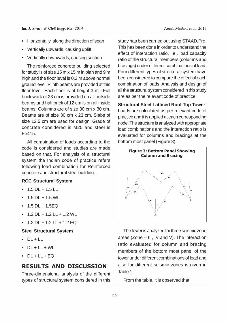
Structural Steel Latticed Roof Top Tower:Loads are calculated as per relevant code ofpractice and it is applied at each correspondingnode. The structure is analyzed with appropriateload combinations and the interaction ratio isevaluated for columns and bracings at thebottom most panel (Figure 3).
Figure 3: Bottom Panel ShowingColumn and Bracing
The tower is analyzed for three seismic zone
areas (Zone – III, IV and V). The interaction
ratio evaluated for column and bracing
members of the bottom most panel of the
tower under different combinations of load and
also for different seismic zones is given in
Table 1.
From the table, it is observed that,

117
Int. J. Struct. & Civil Engg. Res. 2014 Amala Mathew et al., 2014
Interaction ratio on bracing and columnmembers under Dead load and Seismiccombination is very less. This is due to thelesser self-weight of the tower.
Interaction ratio on bracing and columnmembers under Dead and wind load (Normal)when compared with Dead and wind load(Diagonal) combination is higher. This is dueto the lesser lever arm under normal condition.
The axial force on the column and bracingmembers increases as the seismic zonechanges (zone – III to IV and V) this is due tothe increase in horizontal co-efficient (Ah).
Reinforced Concrete Building(Symmetrical): This symmetrical reinforcedconcrete building is of size 15 m x 15 m inplan and 9 m high. It is a three-storey and threebay residential building. The structuralmembers such as columns, beams, slab andfoundations are of M25 grade and Fe415 steel.Loads considered in the model are dead load,live load, wind load and seismic load. Loadsare calculated as per relevant code of practiceand it is applied at each correspondingmember and node.
The structure is analyzed with appropriateload combinations and the interaction ratio isevaluated only for columns at the ground floorlevel (Figure 4).
The reinforced concrete symmetricalbuilding is analysed for three seismic zoneareas (Zone – III, IV and V). The interactionratio evaluated for column members of size350 mm x 350 mm with 1.97% reinforcementat selected four different locations at theground floor level of the building under differentcombinations of load and also for differentseismic zones is given in Table 2.
From the table, it is observed that,
Effect of wind loading on the Interaction ratioon column members under Dead load andwind combination is less than the Dead loadand seismic combination. This is due to the
Figure 4: 3-D view of GroundFloor Column Layout
Table 1: Interaction Ratio of Column and Bracing Members
Beam ID Load CaseAxial Force kN Interaction Ratio
Zone III Zone IV Zone V Zone III Zone IV Zone V
428 DL+WL(N) 205.24 205.24 205.24 0.639 0.639 0.639
428 DL+WL(D) 175.24 175.24 175.24 0.546 0.546 0.546
428 DL+EQ(X) 8.72 9.41 10.40 0.029 0.029 0.032
432 DL+WL(N) 24.23 24.23 24.23 0.646 0.646 0.646
432 DL+WL(D) 20.72 20.72 20.72 0.552 0.552 0.552
432 DL+EQ(X) 1.24 1.34 1.48 0.036 0.036 0.039
118
Int. J. Struct. & Civil Engg. Res. 2014 Amala Mathew et al., 2014
heavier mass of the building which increasesthe seismic load on the structure.
Interaction ratio on column members underDead, live and seismic load is less whencompared with Dead and seismic loadcombination. This is due to the reason that thelive load in the structure reduces the momentinduced due to seismic load condition.
The interaction ration on the columnmembers increases as the seismic zonechanges (Zone – III to IV and V) this is due tothe increase in horizontal co-efficient (Ah).
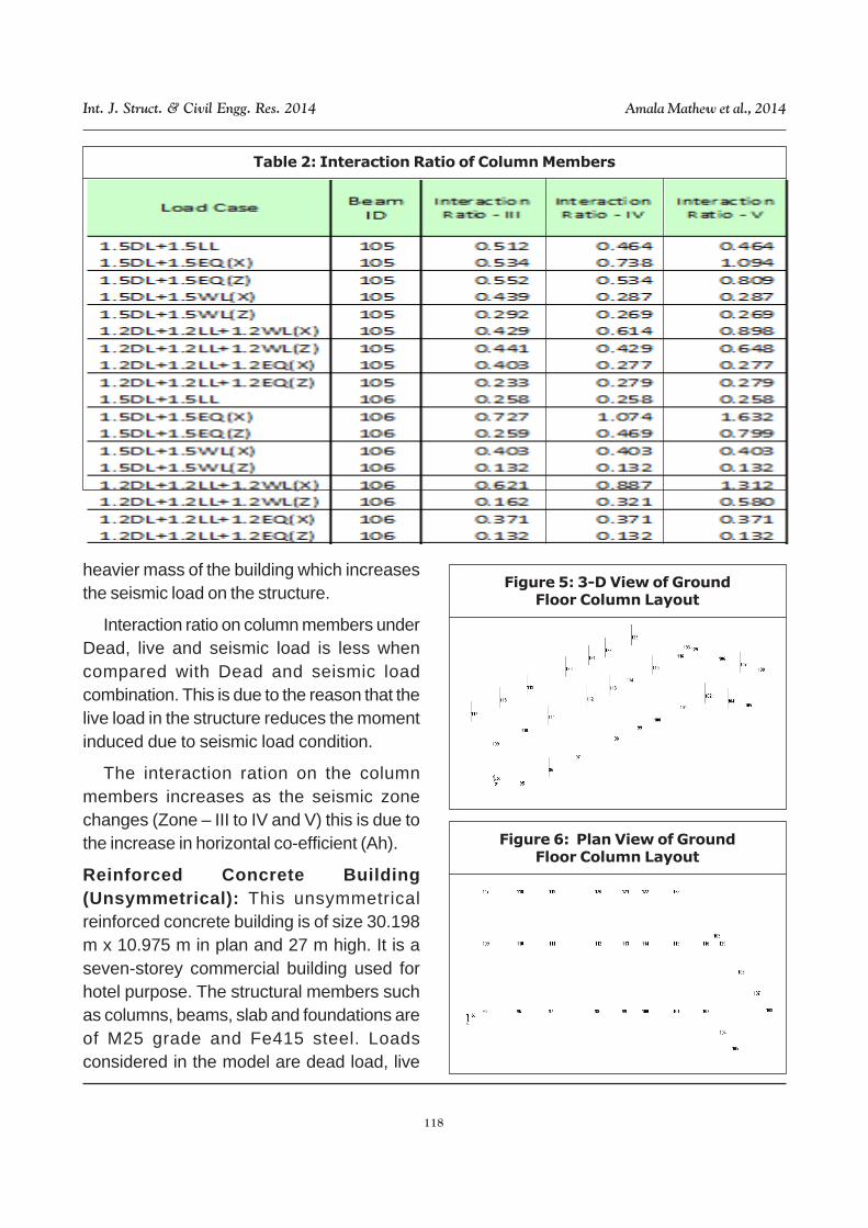
Reinforced Concrete Building(Unsymmetrical): This unsymmetricalreinforced concrete building is of size 30.198m x 10.975 m in plan and 27 m high. It is aseven-storey commercial building used forhotel purpose. The structural members suchas columns, beams, slab and foundations areof M25 grade and Fe415 steel. Loadsconsidered in the model are dead load, live
Table 2: Interaction Ratio of Column Members
Figure 5: 3-D View of GroundFloor Column Layout
Figure 6: Plan View of GroundFloor Column Layout

119
Int. J. Struct. & Civil Engg. Res. 2014 Amala Mathew et al., 2014
load, wind load and seismic load. Loads arecalculated as per relevant code of practice andit is applied at each corresponding memberand node. The structure is analyzed withappropriate load combinations and theinteraction ratio is evaluated only for columnsat the ground floor level (Figures 5 and 6).
The unsymmetrical reinforced concretecommercial building is analyzed for dead, live,wind and seismic load (Zone – III). Theinteraction ratio evaluated for columnmembers of size 550 mm x 550 mm with
2.077% reinforcement at few different selectedlocations at the ground level of the buildingunder different combinations of load is givenin Table 3.
From the table, it is observed that,
Effect of wind loading on the Interaction ratioon column members under any combinationof dead, live and wind load is less than anycombination of dead, live and seismic load.This is due to the heavier mass of the buildingwhich increases the seismic load on the
Table 3: Interaction Ratio of Column Members

120
Int. J. Struct. & Civil Engg. Res. 2014 Amala Mathew et al., 2014
structure.
Interaction ratio on column members underDead, live and seismic load is less whencompared with Dead and seismic loadcombination. This is due to the reason that thelive load in the structure reduces the momentinduced due to seismic load condition.
The interaction ratio on the column membersunder seismic loading combination is alwayshigher than any other combination. Thisindicates that the seismic loading alwaysgoverns for the building with heavy mass eventhough at the higher wind speed locations.
Structural Steel Industrial Building: Loadsconsidered in the model are dead load, liveload, wind and seismic load. Loads arecalculated as per relevant code of practice andit is applied at each corresponding memberand node. The structure is analyzed withappropriate load combinations and theinteraction ratio is evaluated only for columnsat the ground floor level (Figures 7 and 8).
The structural steel industrial building isanalysed for dead, live, wind and seismic load(Zone – III). The interaction ratio evaluated forcolumn members for I section of Indianstandard steel ISHB400 at few selectedlocations of the building under different
Figure 7: 3-D View of Column Layout
Figure 8: Plan View of Column Layout
Table 4: Interaction Ratioof Column Members
combinations of load is given in Table 4 .
From the table, it is observed that,
Effect of wind loading on the Interaction ratioon column members under any combinationof dead, live and wind load is less than anycombination of dead, live and seismic load.This is due to the heavier mass of the buildingwhich increases the seismic load on thestructure.
Interaction ratio on column members underdead, live and seismic load is high when

121
Int. J. Struct. & Civil Engg. Res. 2014 Amala Mathew et al., 2014
compared with dead and seismic loadcombination. This is due to the reason that thecontribution of live load live to the seismic loadin the structure is considerably higher whencompared to ordinary residential building.
The interaction ratio on the column membersunder dead and wind or seismic loadingcombination is always lower than dead andlive load combination. This is due to high liveload of the industrial building.
CONCLUSION
Based on the study on three-dimensionalanalysis of different types of structural systemusing STAAD.Pro for evaluation of interactionratio of the column and bracing members underdifferent combinations of loading, theconclusions were derived as follows,
Structural Steel Latticed Roof Top Tower:Interaction ratio on bracing and columnmembers under dead load and seismiccombination is very less when compared withother combinations of load. This is becausedead load (including self-weight and otherpermanent loads) acting on the steel latticedtower is very less when compared to reinforcedconcrete building. Seismic load acting on anystructure is proportional to the dead load plusa percentage of live load. In case of towerstructures the dead load component is veryless which leads to lesser seismic force. It isalso observed that even at higher seismiczones the effect of seismic load on the towermember is insignificant. Wind load plays asignificant role in the design of tower membersdue to the geometry and the slenderness ofthe tower.
Reinforced Concrete Building
(Symmetrical): Interaction ratio on columnmembers under dead and wind loadcombination is less than the dead and seismicload combination. This is due to the reasonthat in case of residential concrete building thedead and live load acting on the building ishigh, which results in higher seismic load.
Similarly, the effect of interaction ratio oncolumn members under dead and live load issame for different column positions, whereasthe interaction ratio of column members underseismic load varies, i.e., for the corner andexterior column, the response under seismicloads will be high and for interior columns it isvery less this is due to the lever arm distanceof the columns from the centre of gravity of thebuilding.
Reinforced Concrete Building(Unsymmetrical): Interaction ratio on columnmembers under dead and wind loadcombination is less than the dead and seismicload combination. This is due to the reasonthat in case of concrete building the dead andlive load acting on the building is high, whichresults in higher seismic load.
In unsymmetrical slender building, theconcentration of seismic load is higher as thelumped mass at the higher levels will result inhigher moment (force multiplied by height). Thisalways results in higher interaction ratio on thecolumn members under seismic loads.
Structural Steel Industrial Building:Interaction ratio on column members underdead, live and seismic load is high whencompared with dead and seismic loadcombination. This is due to the reason that,generally the behavior of steel structures under

122
Int. J. Struct. & Civil Engg. Res. 2014 Amala Mathew et al., 2014
seismic load is very insignificant whencompared to wind load. This is not true whenthe magnitude of the live load acting on thestructure is high. Due to this the seismic loadbecomes significant and it plays an importantrole in the design.
From the above conclusion, it is very wellunderstood that Dead and live load plays amajor role in the seismic load calculation.Slender steel structural systems are alwaysgoverned by the wind load. Whereas, steelstructural system with heavier live load,seismic load governs the design. In case ofbuildings with magnitude of dead load and liveload is high, than the interaction ratio on thestructural member under seismic load will bealways governs and vice versa. Distribution ofthe seismic force to the structural memberswill be uniform if the columns are placedsymmetrically. Non-uniform distribution ofcolumn forces will result in torsion in thestructural components and the rate of damagewill be very high.
It is also noted that interior columns in thestructural system which is designed for seismiczone III is also adequate when it is checkedunder the seismic zone IV. The exteriorcolumns in the same structural system whichis found inadequate should be strengthenedby using retrofitting to take care of theadditional seismic load. This will avoid furtherdamage to the structure and its componentsunder higher unexpected earthquakes.
ACKNOWLEDGMENT
The authors thanks The Director, CSIR-SERC,Chennai for the help provided duringpreparation of the paper.
REFERENCES
1. Awkar J C and Lui E M (1997), “Seismicanalysis and response of multistorysemirigid frames”, Journal of EngineeringStructures, Vol. 21, No. 5, pp. 425-442.
2. Garcia Reyes, Hajirasouliha Iman andPilakoutas Kypros (2010), ”Seismicbehaviour of deficient RC framesstrengthened with CFRP composites”,Engineering Structures, Vol. 32, pp.3075-3085.
3. Hoxey R P (1991), “Structural responseof a portal framed building under windload”, Journal of Wind Engineering andIndustrial Aerodynamics, Vol. 38, Nos.2-3, pp. 347-356.
4. IS 1893 (Part 1): 2002,” Criteria forEarthquake Resistant Design ofStructures”, Bureau of Indian Standards,New Delhi.
5. IS 456: 2000, “Plain and ReinforcedConcrete-Code of Practice”, Bureau ofIndian Standards, New Delhi.
6. IS 800: 1984, “General Construction inSteel -Code of Practice”, Bureau ofIndian Standards, New Delhi.
7. IS 802 (Part 1/Sec 1):1995, “Use ofStructural Steel in Overhead TransmissionLine Towers – Code of Practice”, Bureauof Indian Standards, New Delhi.
8. IS 802 (Part 1/Sec 2):1992, “Use ofStructural Steel In Overhead TransmissionLine Towers — Code of Practice”,Bureau of Indian Standards, New Delhi.
9. IS 875 (Part 3):1987, “Design Loads(Other Than Earthquake) For Buildingsand Structures — Code of Practice”,
123
Int. J. Struct. & Civil Engg. Res. 2014 Amala Mathew et al., 2014
Bureau of Indian Standards, New Delhi.
10. Maison Bruce F and Neuss Carl F.(1985),“Dynamic analysis of a forty four storybuilding”, Journal of StructuralEngineering, Vol. 111, No. 7, pp. 1559-572.
11. Misam and Madhuri M (2012), “StructuralResponse of Soft Story-High RiseBuildings Under Different Shear WallLocation”, International Journal of CivilEngineering & Technology, ISSN 0976– 6316(Online) Vol. 3, No. 2.
12. Praval Priyaranjan (2011) “SeismicEvaluation and Retrofit of A RC FrameStructure”, B.Tech Thesis Report,Department of Civil Engineering, NIT,Rourkela.
13. Taranpreet Singh (2006) “SeismicEvaluation of Reinforced ConcreteBuildings”, ME Thesis Report,Department of Civil Engineering, ThaparInstitute of Engineering & Technology,Patiala.