research on the marine shafting torsional vibration with ... · 2. model marine propulsion shafting...
TRANSCRIPT

Research on the Marine Shafting Torsional Vibration with Gears Transmission
Xiang Xu1,a, Ruiping Zhou1,b, Mengsheng Wang1,c
1College of Energy and Power Engineering, Wuhan University of Technology. Wuhan, China [email protected], [email protected],c [email protected]
Abstract
The torsional vibration of marine propulsion shafting has been studied for more than a century. With abundant research achievements and experiences, a systematic approach of vibration calculation has been put forward for ship industrial applications. However, literature review indicates that when processing the gear transmission in the shaft line, the meshing motion has been treated as rigid mass in the equivalent equation of energy conservation, which leads to a certain error between the theoretical and experimental results of torsional vibration. Hence, to improve the calculation accuracy, a new method which considers the gear meshing stiffness is proposed in this paper. By taking the propulsion shafting of 3700DWT IMO TYPE II CHEMICAL TANKER as the research object, the forward computing formula of the shaft torsional vibration was first obtained using gear system dynamics theory. Then, the gear mesh stiffness was derived from the length variation of gear contact line. Finally, the free torsional vibration frequency was calculated considering the influence of the gear meshing force. The real marine test was implemented to verify the proposed method. The calculation results show that the new approach can track the actual torsional vibration more precisely than that without taking the gear meshing impact into account.
Keywords: Marine Shafting, Torsional Vibration, Gears Transmission
1. Introduction
According to the marine propulsion shafting vibration form, the vibration can be divided into torsional vibration, longitudinal (axial) vibration and whirling vibration, and the torsional vibration, as the most harmful and the easiest resonant vibration form, becomes the focus of marine propulsion shaft research.
Up to date many shafting vibration models have been applied into calculation of shafting torsional vibration. Discretization lumped parameter model, which simplifies the marine shafting into rigid homogeneous disc component, non-inertia damping elements and non-inertial torsion spring component, is one of the earliest mechanical model, and the advantages are the clear physical concept, simple using and calculation easily. Besides, there are two other continuous distributed parameter model, frame model and stepped shafts model, are being used to calculate the shafting torsional vibration. Bargis [1] got the frame model by using circular section straight beam instead of main journal and crank pin and using variable cross-section rectangular beam instead of crank arm and counterbalance when calculating crankshaft vibration with finite element method (FEM). Okamura [2] also obtained the frame model by using simple rectangular beam instead of crank arm and counterbalance. Mioduchowski [3] proposed the stepped shafts model to calculate the free vibration of a multi-mass drive system based on the theory of propagation of one dimensional torsional elastic waves. And Nadolsk [4] adopted the same model to solve the problem of crankshaft torsional vibration, in which the piston linkage mechanism additional mass was assigned to the two crank arm, and the unit crank was simplified as a set of concentric stepped shaft.
In order to solve marine shafting torsional vibration, many methods were put forward, Holzer method, transfer matrix method and analytical method were used for free vibration calculation. Energy method, amplification coefficient method, the transfer matrix method, analytical method and finite element method were used for forced vibration calculation. Holzer method is the traditional shafting
Research on the Marine Shafting Torsional Vibration with Gears Transmission Xiang Xu, Ruiping Zhou, Mengsheng Wang
International Journal of Engineering and Industries(IJEI) Volume3. Number1. March 2012 doi: 10.4156/IJEI.vol3.issue1.10
99

torsional vibration natural frequency and vibration mode calculation method [5, 6]. According to its basic principle, Holzer method or Tolle method were often used in engineering manual calculation [7].
In recent years, with the popularization and application of computers, some theory, such as matrix analysis, linear algebra, etc., were introduced into torsional vibration calculation, hence numerical calculation method and corresponding calculation program including transfer matrix method are developed based on Holzer method [8]. The transfer matrix method was established for study elastic components of one-dimensional linear system vibration Method in 1920s. Pestel and Leckie [9] in their column outlined the transfer matrix of some typical elastic mechanics elements. Rubin [10] proposed the general treatment of the transfer matrix and the relationship between the transfer matrix and other forms of frequency response matrix. The basic idea is to split the system into a series of components with simple dynamic properties. The vibration state of the system can be described by the state vector of each component. The state vector between two end points of each two components presents the dynamic characteristics of each component, which can be expressed as the transfer matrix of the component. So the system vibration characteristics could be obtained by transfer matrix of each element and systems boundary conditions [11]. Huang and Horng [12] extended the transfer matrix method using complex numbers to analyze the torsional vibration for damping systems.
Compared with the transfer matrix method, finite element method requires more computer memory and time, and the program is more complex. However, this is no longer a problem with the rapid development in computer today, so the finite element method has been developed rapidly. In 1973, finite element method was first applied in the crankshaft dynamics dynamic analysis [13]. Later, finite element method is more widely used to study the marine propulsion shafting vibration problems -not only in torsional vibration, but also in the axial vibration, whirling vibration and coupled vibration [14]. Zou [15] proposed a modal synthesis method of torsional vibration analysis for complicated multi-branched system, which is divided into several substructures that are analyzed by FEM (finite element method) except the special elastic-coupling part that is defined as flexible substructure and treated individually, and the results show that the above kind of multi-branched shafting system can be analyzed effectively. Giancarlo [16] summarized the calculation methods of crankshafts torsional vibration. So far, although the marine propulsion shafting torsional vibration calculation and testing methods have to meet the engineering needs, there are still many problems in torsional vibration treatment in both theory and practice, and the key point is how to accurately determine the dynamic parameters such as inertia, damping and stiffness in torsional vibration calculation. Ref. [17] gives a large number of processing methods and formulas in marine propulsion shafting free and forced torsional vibration calculation, and in its model the meshing gears were processed on a whole, in which the components rotating in different speed were transformed into the equivalent system in the same speed by equivalent formulas of the moment of inertia, torsional stiffness and torsional damping. However, in fact, there are meshing stiffness and meshing damping, which is non-linear, between the two meshing gears when gears work. Kahraman and Blankenship [18] proposed the equivalent mathematical model of the gear system torsional vibration, and the model can be simplified into a vibration-impact model with time-varying stiffness [19]. Wu and Chen [20] present a simple approach for gear-branched system torsional vibration calculation, in which a gear-branched system was modeled as an equivalent straight-geared (or direct-transmitted) system, then the overall mass matrix, damping matrix, stiffness matrix, and load vector of the direct-transmitted system are obtained with the conventional finite element method (FEM) by assembling the elemental property matrices of all the shaft elements contained in the torsional system.
This paper aims to calculate the marine propulsion shafting torsional vibration with gears transmission. Gear system dynamics theory [21] has been introduced into the torsional vibration calculation of the marine propulsion shafting and the vibration equations with gears transmission were established by using the lumped parameter model. Then a dynamic simulation has been done in MATLAB software, in which the natural frequency of the system has been obtained from the simulation curve by changing the input frequency. The measured results show that the torsional vibration calculation is more accurate when considering the meshing gears transmission.
Research on the Marine Shafting Torsional Vibration with Gears Transmission Xiang Xu, Ruiping Zhou, Mengsheng Wang
100

2. Model
Marine propulsion shafting usually consists of main engine (diesel engine), flexible coupling, gearbox, transmission shafts (intermediate shaft, propeller shaft) and propeller. Marine propulsion shafting torsional vibration calculation generally uses lumped parameter model. Taking the propulsion shafting of 3700DWT IMO TYPE II CHEMICAL TANKER for example, its equivalent diagram is shown in Fig. 1.
111216
13
1415
17
18
19
20
21
2223
clutch A
clutch BDiesel engine
Flexible coupling
Gearbox
Shafting
Propeller109
8
674532
1
Figure1. The equivalent diagram of 3700DWT IMO TYPE II CHEMICAL TANKER
Figure2. The calculation equivalent diagram
Gearbox, as an important part of the propulsion device, not only reduces the output speed of diesel
engine down to the most efficient speed of propeller, thus get the best propeller efficiency; but also enables forward and backward functions of the propulsion shaft. And its vibration problem has to be resolved due to its characteristics of big power transmission, high speed and large gears bearing capacity. Component 13, component 15, component 16, component 21, component 23 in fig. 1 are
gears, and there are two hydraulic clutches between component 13 and component 14(namely clutch
A) and between component 21 and component 22(namely clutch B) respectively. In the structure of the gearbox, the functions which the output shaft flange can positive rotate or inverse rotate can be achieved in marine propulsion system. When the rotation directions of engine and propeller are different, clutch A is connected while clutch B is disengagement, so the power transmission line of the gearbox is 12→13→14→15→16→17, while gear 13 takes gear 21 rotation and gear 16 drives gear 23 and component 22 rotation. The calculation equivalent diagram was transformed in fig. 2. If the
Research on the Marine Shafting Torsional Vibration with Gears Transmission Xiang Xu, Ruiping Zhou, Mengsheng Wang
101

rotation directions of engine and propeller are the same, then clutch A is disengagement while clutch B is connected, the power transmission line of the gearbox is 12→13→21→22→23→16→17. 3. Analysis and Calculation
From Fig.2 the torsional free vibration equation is defined as below
}0{}]{[}]{[ kJ (1)
Where ][J , ][k , }{ , }{ represent the total mass matrix, total stiffness matrix, angular acceleration vector and angular displacement respectively.
According to Ref. [17], in the transmission system, each shaft runs in different speed, so transmission system with different speed is often transformed into an equivalent system with the same rotation speed, and in engine propulsion shafting the diesel engine speed is often treated as the standard speed in the torsional vibration calculation. Meanwhile, the meshing gears are processed as one component, or the stiffness between the gears is infinite Equivalent inertia and equivalent stiffness calculation formula is given in (2).
fl JiJ 2 , fl kik 2 (2)
Where subscript f and l represent the physical quantity after and before equivalent calculation respectively. Transmission ratio lf nni / . According to the special structure of marine gearbox, the equations are as bellow:
21
131 n
ni ,
16
22
16
152 n
n
n
ni (3)
Therefore, the total mass matrix could be written as:
20
19
2
1
][
a
a
a
a
J (4)
Where
11 Ja , 22 Ja , …, 21211313 JiJa , 1414 Ja , …, 16
22221515 JiJJa , 17
2216 Jia ,
…, 202219 Jia , 2320 Ja
And the total stiffness matrix could be defined as:
Tbbbbk 201921][ (5)
Where
20111 ],0,,[ kkb ,
2022112 ],0,,,[ kkkkb
2033223 ],0,,,,0[ kkkkb
…
202116222116
22141415 ],0,0,0,,,0,,0[ kkikkikkb
20172217
2216
2216
22
14
16 ]0,,,0,0[ ,,kikikikib
…
20192219
2219 ]0,,,0,,0[ kikib
Research on the Marine Shafting Torsional Vibration with Gears Transmission Xiang Xu, Ruiping Zhou, Mengsheng Wang
102
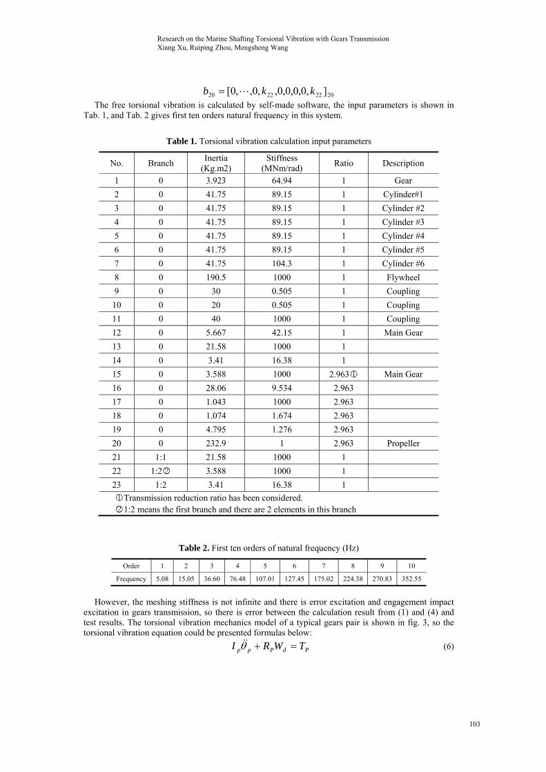
20222220 ],0,0,0,0,,0,,0[ kkb The free torsional vibration is calculated by self-made software, the input parameters is shown in
Tab. 1, and Tab. 2 gives first ten orders natural frequency in this system.
Table 1. Torsional vibration calculation input parameters
No. Branch Inertia
(Kg.m2) Stiffness
(MNm/rad) Ratio Description
1 0 3.923 64.94 1 Gear
2 0 41.75 89.15 1 Cylinder#1
3 0 41.75 89.15 1 Cylinder #2
4 0 41.75 89.15 1 Cylinder #3
5 0 41.75 89.15 1 Cylinder #4
6 0 41.75 89.15 1 Cylinder #5
7 0 41.75 104.3 1 Cylinder #6
8 0 190.5 1000 1 Flywheel
9 0 30 0.505 1 Coupling
10 0 20 0.505 1 Coupling
11 0 40 1000 1 Coupling
12 0 5.667 42.15 1 Main Gear
13 0 21.58 1000 1
14 0 3.41 16.38 1
15 0 3.588 1000 2.963○1 Main Gear
16 0 28.06 9.534 2.963
17 0 1.043 1000 2.963
18 0 1.074 1.674 2.963
19 0 4.795 1.276 2.963
20 0 232.9 1 2.963 Propeller
21 1:1 21.58 1000 1
22 1:2○2 3.588 1000 1
23 1:2 3.41 16.38 1
○1 Transmission reduction ratio has been considered. ○2 1:2 means the first branch and there are 2 elements in this branch
Table 2. First ten orders of natural frequency (Hz)
Order 1 2 3 4 5 6 7 8 9 10
Frequency 5.08 15.05 36.60 76.48 107.01 127.45 175.02 224.38 270.83 352.55
However, the meshing stiffness is not infinite and there is error excitation and engagement impact
excitation in gears transmission, so there is error between the calculation result from (1) and (4) and test results. The torsional vibration mechanics model of a typical gears pair is shown in fig. 3, so the torsional vibration equation could be presented formulas below:
PdPpp TWRI (6)
Research on the Marine Shafting Torsional Vibration with Gears Transmission Xiang Xu, Ruiping Zhou, Mengsheng Wang
103

gdggg TWRI (7)
)()( eRRkeRRcW ggppmggppmd (8)
Where subscript p and g represent the driving gear and driven gear respectively, R is the base circle radius, mc and mk represent the damping and stiffness respectively, dW is the gears dynamic meshing force, and e is the gears meshing comprehensive error.
Figure.3 Gears pair torsional vibration model
According to non-linear dynamic equations of gear system and the propulsion shafting vibration free vibration equation, the non-linear dynamic equation of some components considering transmission gear mesh stiffness, and transmission clearance could be given as:
12013132121201314131213121313 )()()( ekRRkkkJ
321215161621232116171615151616151616 )()()( ekekRRkkRRkJ
12013132121202121 )( ekRRkJ
0)( 2223222222 kJ
32122232216162323212323 )()( ekkRRkJ The system could be rewritten in matrix form:
}{}{}{ PkJ (9)
Where
23
2
1
][
J
J
J
J
, T},,{}{ 2321 , Tdddk },,{ 2321
23111 ],0,,[ kkd ,
2322112 ],0,,,[ kkkkd
2333223 ],0,,,,0[ kkkkd
…
2320211313202
13131212
11
13 ]0,0,,0,,0,,,,0,,0[ kRRkkRkkkd
2314141313
12
14 ],0,,,,0,,0[
kkkkd
Research on the Marine Shafting Torsional Vibration with Gears Transmission Xiang Xu, Ruiping Zhou, Mengsheng Wang
104

23151615152
151414
13
15 ],0,,,,0,0[
kRRkRkkd ,
2321231616212
1616152
16151615
14
16 ],0,,0,,,,0,,0[ kRRkkRkkRkRRd
2317171616
15
17 ],0,,,,0,,0[
kkkkd
…
23191920 ]0,0,0,,0,,0[ kkd
2320221202113
12
21 ]0,0,,0,,0,,0,,0[ kRkRRd
23222222 ],,0,,0[ kkd
23222122322212316
15
23 ],,0,0,,0,,0[ kkRkkRRd
T},0,,0,0,0,0,,,,0,,0,,0{}{ 321231202132116215162151512013
12
ekRekRekRekRekRekRP
4. Simulation 4.1 Mesh stiffness
In order to solve the time-varying mesh stiffness of the gears pair, the change of the contact line length of the gears pair was used instead of the instantaneous gear mesh stiffness for the ideal accuracy marine helical gears pair [22]. When the mesh stiffness of the unit contact line length 0k is constant, the mesh stiffness is defined as:
)()()( 00 LktLktK (10)
Where )(tL is the instantaneous total contact line length of gears pair. And it could be calculated by the following formula:
)()()()()(1
010 itltltltltL
P
iin
(11)
cos/)()( BtBtl ii (12)
Where B is the tooth width, is the helical gear helix angle. For helical gears transmission, the shape of each tooth could be considered as the same, then the contact change in gears meshing can be considered as periodicity, therefore it can be expanded by Fourier series form, so there is:
)2
sin2
cos(2
)(1
0
P
ntb
P
nta
atB n
nni
(13)
Pa a2
0 , ]1)(2
cos2
cos2
[cos2
122
P
n
P
n
P
n
na baab
b
n
])(2
sin2
sin2
[sin2
122 P
n
P
n
P
n
nb baab
b
n
Research on the Marine Shafting Torsional Vibration with Gears Transmission Xiang Xu, Ruiping Zhou, Mengsheng Wang
105

Figure 4. The gears pair 15-16 and Figure 5. The meshing stiffness of the
16-23 meshing stiffness (f=10Hz) different gears pairs (f=10Hz)
Where a is the gears pair transverse contact ratio, b is the gears pair axial contact ratio and P is
the gears meshing number. Fig. 4 shows the meshing stiffness of the gears pairs 15-16 and 16-23 with an input frequency of
10Hz, and Fig. 5 shows the different gears pair meshing stiffness curves. From the figures, we can see that the meshing stiffness amplitude of the meshing gears pair remained didn’t change, but there are periodic changes in the frequency which varies with input frequency.
4.2 Gears meshing comprehensive error
Figure 6. The gears pair 13-21 meshing Figure 7. The gears pair 15/23 -16 meshing
comprehensive error curve (f=10Hz) comprehensive error curve (f=10Hz)
Gears meshing comprehensive error is affected by design precision and manufacture error, and it is very difficult to determine it in theoretical calculation, so the tooth pitch cumulative tolerances can be used instead of the gears meshing comprehensive error, generally it could be considered as:
tiFtFe PP sinsin 21 (14)
Where 1PF and 2PF are the tooth pitch cumulative tolerances of two meshing gears respectively,
is the shaft rotation frequency and i is the gears transmission ratio. Fig. 6 and Fig. 7 show the comprehensive meshing error of gears pair 13-21 and gears pair 15-16 when the input frequency is 10Hz.
4.3 System Vibration
According to (9), when taking damping into account, each component’s dynamic equation could be written as below:
Research on the Marine Shafting Torsional Vibration with Gears Transmission Xiang Xu, Ruiping Zhou, Mengsheng Wang
106

iiiiiiiiiiiiiii TkckcJ )()()()( 11111 (15)
It is rewritten as:
iiiiiiiiiiiiiii JkckcT /)]()()()([ 11111 = (16)
Some damping is given by the producer, while shaft torsional damping and gears meshing damping could be calculated as [23]:
)11
/(2ji
ijsij JJkc (17)
)(222
222
ijijjjii
jijiij kgk
JzJz
JJzzmc
(18)
Where ijk is the stiffness between the mass points, iJ and jJ are the moment of inertia of the mass points, z is the teeth of gear, m is module, s and are the damping ratio, according to research results, s usually variess from 0.005 to 0.075 and usually varies from 0.03 to 0.17.
Figure 8. Input shaft torque curve (10Hz)
According to analysis above, the gears meshing stiffness , meshing damping and
meshing error related of the torque frequency of the input shaft could be written as a function of rotation frequency, so it is difficult to solve (9) using ordinary vibration calculation method. To obtain natural frequency and analyze the vibration influence of parameters of the gears system, the simulation calculation in MATLAB/SIMULINK has been done in following work and four-order-Runge-Kutta method was used to solve the nonlinear equations, in which the input shaft torque is taken as input and the output shaft angular acceleration is taken as output.
First, the input shaft torque amplitude is set as 10N.m, frequency is set as 10Hz, and the achieved torque curve is shown in Fig. 8, so the intermediate shaft angular velocity curve is obtained in this frequency in 0.5 seconds and 10 seconds, which are shown in Fig. 9 and Fig. 10.
Research on the Marine Shafting Torsional Vibration with Gears Transmission Xiang Xu, Ruiping Zhou, Mengsheng Wang
107

Figure 9. Intermediate shaft angular Figure 10. Intermediate shaft angular
velocity curve in 0.5s (10Hz) velocity curve in 10s (10Hz)
From the Fig. 10, we can see that there is a tiny fluctuation on the angular velocity curve, the reason of this phenomenon may be the periodicity variation of the gears meshing stiffness and the gears pair comprehensive meshing error.
Fig. 11 shows the Intermediate shaft angular velocity curve in different input frequency (10Hz, 15Hz and 25 Hz). Theoretically, the waveforms figure in the arbitrary input frequency could be gotten by this method in the suitable step, and the extreme points, which are the inherent frequency of the propulsion shafting, could be found by Fourier transform in the frequency domain.Although the nonlinear equation and the simulation results have been obtained, the method is too complicated for practical application. If using the average meshing stiffness and damping instead of the meshing stiffness and damping fluctuations, and ignoring the gears meshing comprehensive error, the simulation results are shown in Fig. 11 (still in 10Hz).
From Fig. 12, comparing linear results with nonlinear results, one difference is that the amplitude in linear is smaller than in nonlinear, and there are changes from linear to nonlinear in transitional stage, which are caused by gears meshing comprehensive error. Meanwhile, another difference is the trend in linear is more smooth than in nonlinear because of the fluctuations of the meshing stiffness and damping. However, the waveform, especially the main wave frequency, are similar between in linear and in nonlinear, so the nonlinear results could be replaced by linear results, and the (9) results calculated by normal matrix calculation method was shown in Tab.3 (only first ten orders natural frequency) ignoring meshing error and using average meshing stiffness instead of the rigid connection.
Figure 11. Intermediate shaft angular Figure 12. Angular velocity curve
velocity curve in different input frequency in nonlinear and linear
Research on the Marine Shafting Torsional Vibration with Gears Transmission Xiang Xu, Ruiping Zhou, Mengsheng Wang
108

Table 3. First ten orders of natural frequency considering meshing stiffness (Hz)
Order 1 2 3 4 5 6 7 8 9 10 Frequency 2.69 6.78 13.01 36.12 45.85 55 122.21 128.22 154.38 198.92
5. Test
The sweep-frequency measurement method is used to measure the shafting resonance point: first get enough instantaneous physical quantities (angular displacement, angular velocity or angle acceleration) of the measuring points in measuring interval (based on engineer average speed), then find the extreme points in frequency domain in each harmonic times by Fourier transform, and observe the extreme points time-domain, if the presented peak times is consistent with the harmonic times, this point is the natural frequency, otherwise, it is not the resonance point.
Figure 13. Rotary encoder arrangement Figure 14. The flow chart of the test method
The torsional vibration sensor was installed on intermediate shaft by belt disc, so the instantaneous speed of intermediate shaft could be gotten according to the encoder pulse number and the radius ratio between the disc and the intermediate shaft. Fig. 13 shows the installation position. The signals of the torsional vibration were sampled and sent to the laptop computer. The signals were analyzed by the frequency spectrum analyzer. The arrangement of testing point is shown in Fig. 14. The engine speed were carried out at interval of 10r/min from the lowest stable speed at 280 r/min to the rated speed at 620 r/min and at interval of 10r/min from the rated speed at 620 r/min to the lowest stable speed at 280 r/min, and the test was done and the testing signals results were recorded automatically after the speed was stable (in about 1 minute) [24].
Figure 15. Frequency domain (9th harmonic) Figure 16. The time-domain in 105.35r/min
According to the test results, the resonance speed was found at 9th harmonic times at 105.35r/min. The waves were referred to Fig. 15~16.
Research on the Marine Shafting Torsional Vibration with Gears Transmission Xiang Xu, Ruiping Zhou, Mengsheng Wang
109

The resonance speed (take the engineer speed as base speed) could be calculated as follows:
min/28099963.235.1050 rvinn (19)
Where 0n is the resonance speed of intermediate shaft, v is harmonic times.
So the resonance frequency is 46.82Hz, but it is difficult to find the appropriate resonance point from Tab. 2. However, the fifth order natural frequency is 45.85 Hz in Tab. 3, which is close to measured data, and the error is 2.07%. Hence, the method in marine shafting system torsional vibration is more precise when the gears meshing stiffness is taken into account, though ignoring the meshing stiffness fluctuations and gears meshing comprehensive error. 6. Conclusion
In this paper, the ripe marine propulsion shaft torsional vibration calculation was described by
taking the propulsion shafting of 3700DWT IMO TYPE II CHEMICAL TANKER as the research object, and in order to improve the torsional vibration calculation because of the shortcomings in model simplification, some work has been done:
1) The method considering the gears dynamic meshing of marine shafting torsional vibration calculation has been derived and the improved vibration equation has been obtained.
2) The simulation curves of the gears meshing stiffness and gears comprehensive meshing error have been gotten.
3) The intermediate shaft angular velocity simulation curves in the gears system have been gotten through changing the input torque frequency, and theoretically the resonances could be obtained by using this method as long as there are enough simulation times.
4) The real marine test has been done and the results show that the new approach can track the actual torsional vibration more precisely than that without taking the gear meshing impact into account. Acknowledgment
This paper is sponsored by the National High Technology Marine Research Projects of China (No. JSHT (2009)-001). References [1] E. Bargis, A. Garro, and V. Vullo. “Crankshaft Design and Evaluation-Part 2: A Modern Design
Method: Modal Analysis,” Proceedings of the International Conference on Reliability, Stress Analysis and Failure Prevention, Century 2 - Emerging Technology Conferences, San Francisco, CA. 1980.
[2] H. Okamura, A. Shinno. “Simple Modeling and Analysis for Crankshaft Three-Dimensional Vibrations, Part 1: Background and Application to Free Vibrations,” Journal of Vibration and Acoustics, vol. 117, pp. 70-79, 1995.
[3] A. Mioduchowski. “Torsional waves and free vibrations of drive systems with stepped shafts,” Archive of Applied Mechanics, vol. 56, pp.314-320, 1986.
[4] W. Nadolski, T. Szolc. “Dynamic Investigation of the Crankshaft of Three Cylinder Single Bank Engines Using Torsional Elastic Waves,” Proceedingsof the 15thInternational Conference on Dynamic of Machines, Editions of the Academy of Science of the GDR, 1986.
[5] H. Holzer. Die Berechnung der Drehschwingungen, Berlin: Springer, 1921. [6] W. K. Wilson. Practical Solution of Torsional Vibration Problem, London: Campman and Hall,
1963. [7] A. Sarsten. “A Computer Program for Damped Torsional Vibration Using a Complex Holzer
Tabulation,” European Shipbuilding, vol. 6, pp. 138-157, 1962. [8] M. Hundal. “An Extension of the Holzer Method for Redundant Drive Trains,” Journal of
Engineering for Industry, vol. 97, pp. 697-698, 1974. [9] E. C. Pestel, F. A. Leckie. Matrix Method in Elastomechanics, New York: McGraw-Hill Book
Company, 1963.
Research on the Marine Shafting Torsional Vibration with Gears Transmission Xiang Xu, Ruiping Zhou, Mengsheng Wang
110

[10] S. Rubin. “On transmission matrices for vibration and their relation to admittance and impedance,” Journal of Engineering for Industry, vol. 86, pp. 9-21, 1964.
[11] P. Schwibinger, R. Nordmann. “Improvement of a Reduced Torsional Model by Means of Parameter Identification,” Journal of Vibration, Acoustics, Stress, and Reliability in Design, vol. 111, pp. 17-26, 1989.
[12] Y. M.Huang, C. D. Horng. “Analysis of Torsional Vibration Sys tems by the Extended Transfer Matrix Method,” Journal of Vibration as Acoustics, vol. 121, pp. 250-255, 1999.
[13] C. A. Bagci. “Computer method for computing torsional nature frequencies of nonuniform shafts geared system, and curved assemblies,” Proceedings of the 3rd OSU Mechanical Conference, vol. 40, pp. 1-15, 1973.
[14] L. Murawski. “Axial vibrations of a propulsion system taking into account the couplings and the boundary conditions,” Journal of Marine Science and Technology, vol. 9, pp. 171-181, 2004.
[15] C. P. Zou, D. S. Chen, and H. X. Hua. “Torsional Vibration Analysis of Complicated Multi-Branched Shafting System by Modal Synthesis Method,” Journal of Vibration and Acoustics, vol. 125, pp. 317-323, 2003.
[16] G. Giancarlo Vibration Dynamics and Control, Part III:Torsional Vibration of Crankshafts, Springer, pp. 745-788, 2009.
[17] Z. Y. Chen. Ship Propulsion Shaft Vibration, Shanghai Jiao Tong University Press, China 1987 (In Chinese)
[18] A. Kahraman, G. W. Blankenship. “Experiments on nonlinear dynamic behavior of an oscillator with clearance and periodically time-varying parameters,” Journal of Applied Mechanics, vol. 64, pp. 217-226, 1997.
[19] J. J. Wang, R. F. Li, and X. H. Peng. “A survey to nonlinear vibration of gear transmission system,” Applied Mechanics Reviews, vol. 56, pp. 309-329, 2003.
[20] J. S. Wu, C. H. Chen. “Torsional Vibration Analysis of Gear-branched Systems by Finite Element Method,” Journal of Sound and Vibration, vol. 240, pp. 159-182, 2001
[21] R. F. Li, J. J. Wang. Gears system Dynamics, Science Publications, China 1997 (In Chinese) [22] X.Xu, R.P.Zhou. “Research on Torsional Vibration of Gear-Shafting System Based on an
Extended Lumped Parameter Model,” Advanced Materials Research Vols. 143-144, pp. 487-492, 2011.
[23] X.Xu, R.P.Zhou, Z.X.Li. “Virtual Simulation Analysis and Experimental Study on Gear Fault Diagnosis Based on Wavelet Neural Network,” 2010 International Conference on Machine Vision and Human-machine Interface, pp. 55-58. 2010.
[24] R. R. Brian, W. T. Martin, and P. M. Kenneth. "Compensation for encoder geometry and shaft speed variation in time interval torsional vibration measurement," Journal of sound and vibration, vol. 286, pp. 897-920, 2005.
Research on the Marine Shafting Torsional Vibration with Gears Transmission Xiang Xu, Ruiping Zhou, Mengsheng Wang
111