research on risk assessment system for water inrush in the karst tunnel construction based on gis:...
TRANSCRIPT

Tunnelling and Underground Space Technology 40 (2014) 182–191
Contents lists available at ScienceDirect
Tunnelling and Underground Space Technology
journal homepage: www.elsevier .com/ locate / tust
Research on risk assessment system for water inrush in the karst tunnelconstruction based on GIS: Case study on the diversion tunnel groupsof the Jinping II Hydropower Station
0886-7798/$ - see front matter � 2013 Elsevier Ltd. All rights reserved.http://dx.doi.org/10.1016/j.tust.2013.10.005
⇑ Corresponding author. Tel.: +86 13407101758; fax: +86 27 67883507.E-mail address: [email protected] (X. Li).
Xueping Li ⇑, Yunan LiEngineering Faculty, China University of Geosciences, Wuhan, Hubei 430074, China
a r t i c l e i n f o
Article history:Received 17 April 2012Received in revised form 21 April 2013Accepted 10 October 2013Available online 7 November 2013
Keywords:GISWater inrush with geological flawsWater inrush with no geological flawsKarst tunnelJinping II Hydropower Station
a b s t r a c t
This paper studies the risk assessment system for water inrush in the karst tunnel using geographic infor-mation system (GIS) technology to predict dynamically the water inrush risk and to develop appropriateprotective measures. The risk assessment of the water inrush with geological flaws is conducted wherethe weight is set using the analytic hierarchy process (AHP) to establish the assessment models, whereasthat with no geological flaws is made using the rock mass mechanics theories. The technical route to pre-dict the water inrush risk is based on the geological data obtained prior to prospecting, and the predictionis introduced into the assessment system as background database. The geological and underground waterdata during construction are combined to correct the water inrush model parameters. The correctedparameters are used to update the basic database of the assessment, and the updated data are employedto assess the water inrush risk before construction. During this research, GIS is introduced into the spe-cialized model of risk assessment of the water inrush. MAPGIS geographic information system software isselected as the basic platform of GIS, and VC++ is selected as the development tool. The assessment of thewater inrush model adopted in the system is tested in water inrush cases in the auxiliary tunnel in Jin-ping II Hydropower Station. The results validate the reliability of the model. The system realizes a real-time assessment of the water rush in the karst tunnel by providing a relatively correct and direct geolog-ical basis for the design of waterproof tunnel excavation and offers a practical guide on safe tunnelconstruction.
� 2013 Elsevier Ltd. All rights reserved.
1. Introduction posed, water inrush occurs. The passage of the water inrush with
Water inrush in karst tunnel refers to water burst, whose flow isgreater than 0.1 m3/s and exerts some pressure and speed due todamage on the structure of a karst passage in the water-rich zoneor on the tunnel surrounding rock (Li, 2006; Huang et al., 2012).Water inrush in tunnels is characterized by suddenness, highspeed, and high pressure, and it is highly destructive, which cando tremendous damage to construction and operation of tunnelsand damage the environment.
The formation of water inrush passages in a karst tunnel can becategorized into two (Li, 2009). One is the water inrush tunnel withgeological flaws, and the other is the water inrush tunnel with nogeological flaws. The former includes fault, fracture, and karst con-duit (Shi and Singh, 2001). The passage of the water inrush causedby geological flaws is called water inrush with geological flaws. Itsmechanism involves the excavation of the tunnel; once the karstconduit or wide fissure of the front rock crossing the tunnel face(which exists inside the rock and with good connectivity) is ex-
no geological flaws evolves from the complete rock fissures. Thisinrush is called the water inrush with no geological flaws. Withthe tunnel is excavated, new passages for drainage of the under-ground water are created, which damages the original recharge,runoff, and discharge and aggravates the underground water’s ref-ormation on the rock mass. The mechanical reformation of theunderground water includes hydrostatic and hydrodynamic pres-sure, both of which could cause hydraulic fracture in the rocksmass. The deformation and displacement of the fillings on the fis-sure surface, especially the shearing deformation and displace-ment, are caused by the hydrodynamic pressure, which lead tothe fissure’s re-expansion and strengthens the connectivity of thefissures. After the high-pressure water-rich zone and the tunnelare directly connected by the expanded or new fissures, disasteroccurs because the hydraulic barriers of the portion of the imper-meable section are broken through, and underground water rushesin because of the high pressure.
Based on the formation mechanism of water inrush, the riskassessment methods of the water inrush in karst tunnels can beroughly divided into two types. One is the assessment of water in-rush with geological flaws, which is mainly the analysis of factors
X. Li, Y. Li / Tunnelling and Underground Space Technology 40 (2014) 182–191 183
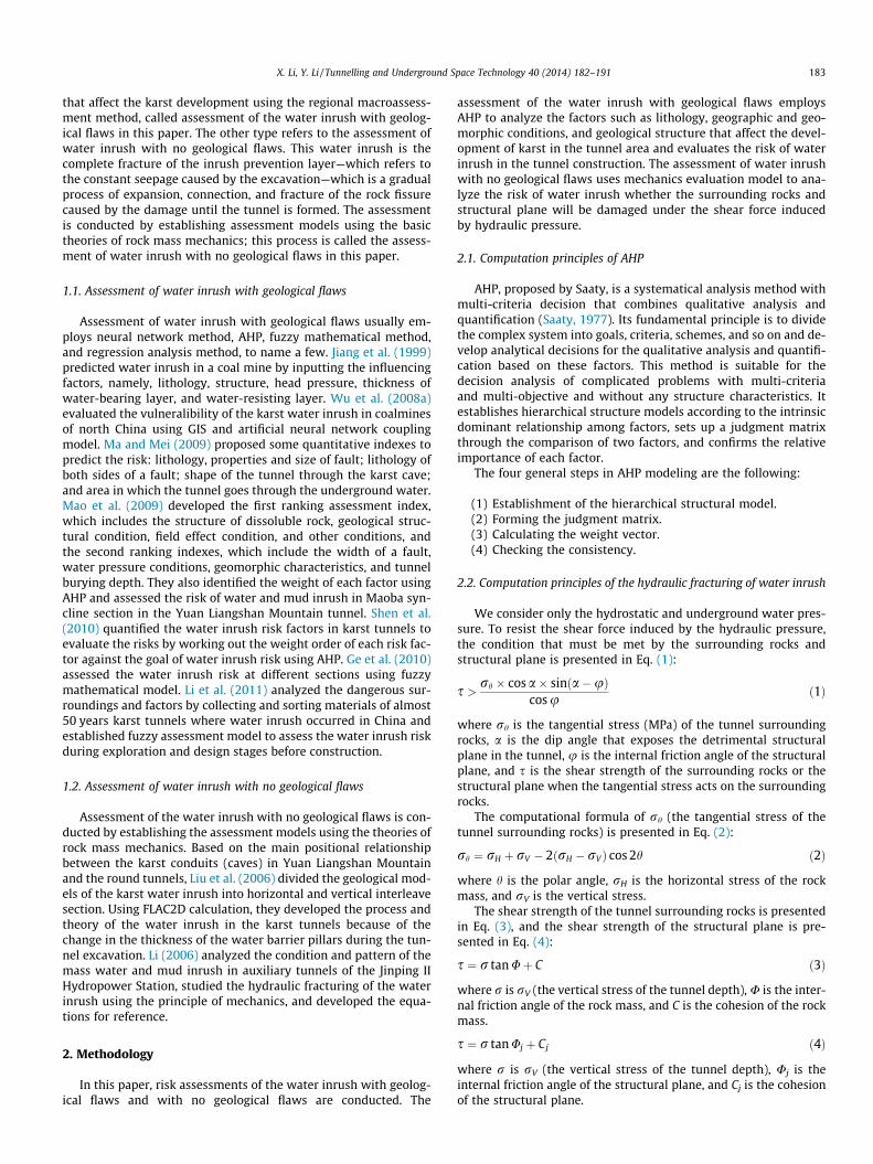
that affect the karst development using the regional macroassess-ment method, called assessment of the water inrush with geolog-ical flaws in this paper. The other type refers to the assessment ofwater inrush with no geological flaws. This water inrush is thecomplete fracture of the inrush prevention layer—which refers tothe constant seepage caused by the excavation—which is a gradualprocess of expansion, connection, and fracture of the rock fissurecaused by the damage until the tunnel is formed. The assessmentis conducted by establishing assessment models using the basictheories of rock mass mechanics; this process is called the assess-ment of water inrush with no geological flaws in this paper.
1.1. Assessment of water inrush with geological flaws
Assessment of water inrush with geological flaws usually em-ploys neural network method, AHP, fuzzy mathematical method,and regression analysis method, to name a few. Jiang et al. (1999)predicted water inrush in a coal mine by inputting the influencingfactors, namely, lithology, structure, head pressure, thickness ofwater-bearing layer, and water-resisting layer. Wu et al. (2008a)evaluated the vulneralibility of the karst water inrush in coalminesof north China using GIS and artificial neural network couplingmodel. Ma and Mei (2009) proposed some quantitative indexes topredict the risk: lithology, properties and size of fault; lithology ofboth sides of a fault; shape of the tunnel through the karst cave;and area in which the tunnel goes through the underground water.Mao et al. (2009) developed the first ranking assessment index,which includes the structure of dissoluble rock, geological struc-tural condition, field effect condition, and other conditions, andthe second ranking indexes, which include the width of a fault,water pressure conditions, geomorphic characteristics, and tunnelburying depth. They also identified the weight of each factor usingAHP and assessed the risk of water and mud inrush in Maoba syn-cline section in the Yuan Liangshan Mountain tunnel. Shen et al.(2010) quantified the water inrush risk factors in karst tunnels toevaluate the risks by working out the weight order of each risk fac-tor against the goal of water inrush risk using AHP. Ge et al. (2010)assessed the water inrush risk at different sections using fuzzymathematical model. Li et al. (2011) analyzed the dangerous sur-roundings and factors by collecting and sorting materials of almost50 years karst tunnels where water inrush occurred in China andestablished fuzzy assessment model to assess the water inrush riskduring exploration and design stages before construction.
1.2. Assessment of water inrush with no geological flaws
Assessment of the water inrush with no geological flaws is con-ducted by establishing the assessment models using the theories ofrock mass mechanics. Based on the main positional relationshipbetween the karst conduits (caves) in Yuan Liangshan Mountainand the round tunnels, Liu et al. (2006) divided the geological mod-els of the karst water inrush into horizontal and vertical interleavesection. Using FLAC2D calculation, they developed the process andtheory of the water inrush in the karst tunnels because of thechange in the thickness of the water barrier pillars during the tun-nel excavation. Li (2006) analyzed the condition and pattern of themass water and mud inrush in auxiliary tunnels of the Jinping IIHydropower Station, studied the hydraulic fracturing of the waterinrush using the principle of mechanics, and developed the equa-tions for reference.
2. Methodology
In this paper, risk assessments of the water inrush with geolog-ical flaws and with no geological flaws are conducted. The
assessment of the water inrush with geological flaws employsAHP to analyze the factors such as lithology, geographic and geo-morphic conditions, and geological structure that affect the devel-opment of karst in the tunnel area and evaluates the risk of waterinrush in the tunnel construction. The assessment of water inrushwith no geological flaws uses mechanics evaluation model to ana-lyze the risk of water inrush whether the surrounding rocks andstructural plane will be damaged under the shear force inducedby hydraulic pressure.
2.1. Computation principles of AHP
AHP, proposed by Saaty, is a systematical analysis method withmulti-criteria decision that combines qualitative analysis andquantification (Saaty, 1977). Its fundamental principle is to dividethe complex system into goals, criteria, schemes, and so on and de-velop analytical decisions for the qualitative analysis and quantifi-cation based on these factors. This method is suitable for thedecision analysis of complicated problems with multi-criteriaand multi-objective and without any structure characteristics. Itestablishes hierarchical structure models according to the intrinsicdominant relationship among factors, sets up a judgment matrixthrough the comparison of two factors, and confirms the relativeimportance of each factor.
The four general steps in AHP modeling are the following:
(1) Establishment of the hierarchical structural model.(2) Forming the judgment matrix.(3) Calculating the weight vector.(4) Checking the consistency.
2.2. Computation principles of the hydraulic fracturing of water inrush
We consider only the hydrostatic and underground water pres-sure. To resist the shear force induced by the hydraulic pressure,the condition that must be met by the surrounding rocks andstructural plane is presented in Eq. (1):
s > rh � cos a� sinða�uÞcos u
ð1Þ
where rh is the tangential stress (MPa) of the tunnel surroundingrocks, a is the dip angle that exposes the detrimental structuralplane in the tunnel, u is the internal friction angle of the structuralplane, and s is the shear strength of the surrounding rocks or thestructural plane when the tangential stress acts on the surroundingrocks.
The computational formula of rh (the tangential stress of thetunnel surrounding rocks) is presented in Eq. (2):
rh ¼ rH þ rV � 2ðrH � rV Þ cos 2h ð2Þ
where h is the polar angle, rH is the horizontal stress of the rockmass, and rV is the vertical stress.
The shear strength of the tunnel surrounding rocks is presentedin Eq. (3), and the shear strength of the structural plane is pre-sented in Eq. (4):
s ¼ r tan Uþ C ð3Þ
where r is rV (the vertical stress of the tunnel depth), U is the inter-nal friction angle of the rock mass, and C is the cohesion of the rockmass.
s ¼ r tan Uj þ Cj ð4Þ
where r is rV (the vertical stress of the tunnel depth), Uj is theinternal friction angle of the structural plane, and Cj is the cohesionof the structural plane.

184 X. Li, Y. Li / Tunnelling and Underground Space Technology 40 (2014) 182–191
The calculated values of the shear strength of the tunnelsurrounding rocks [Eq. (3)] and that of the structural plane [Eq.(4)] should satisfy Eq. (1); otherwise, they are considered as waterinrush.
Fig. 1. Plan of the tunnel group of Jinping II Hydropower Station.
2.3. Technical route of the risk assessment system of the water inrushin karst tunnel construction
In this paper, the systematic research on the risk assessmentof the water inrush in the tunnel construction is conducted inthe following steps: Step 1: Establishment of a background data-base for the risk assessment of the water inrush after the digita-lization of the geological conditions and the tunnel constructionin the research area. Step 2: Quantification of the weight of thefactors that affect the karst development using AHP. Step 3:Dividing the tunnel vertical sections according to their lengthsand dividing the cross sections of each section into differentassessment units according to their mesh sizes. Step 4: Basedon the vertical section division, conducting risk assessment ofthe water inrush with no geological flaws using the weight ob-tained by AHP. The degree of the risk assessment of the waterinrush in each section of the vertical sections is obtained, andthe assessment results are regarded as one of the backgrounddatabases for assessment of the water inrush. Step 5: Calculatingthe underground water pressure, shear force, and shear strengthof the rock and the structural plane of the surrounding units ofeach tunnel’s cross section using the above equations and con-ducting risk assessment of the water inrush with no geologicalflaws. The assessment results are regarded as one of the back-ground databases for the assessment of the water inrush. Step6: Combining the detected-water information during the con-struction, upgrading the background databases of the water in-rush assessment, making zoning charts of the real-time risk ofthe water inrush, and assessing the risk of the water inrush inthe tunnel construction.
3. Calculation
3.1. Introduction to research area
3.1.1. Introduction to the projectJinping II Hydropower Station, an important cascade hydro-
power station along Yalong River, is located on the Jinping RiverBend where the Mili Tibetan Autonomous County, YanyuanCounty, Mianning Country, and Liangshan Yi Autonomous Prefec-ture converge in Sichuan Province. The 150 km natural drop ofthe Bend downstream the Yalong River can produce gross installedcapacity of 4800 MW through the power tunnel groups. The Jin-ping II Hydropower Station tunnel group is a large, deep-buriedtunnel group consisting of four diversion tunnels, two auxiliarytunnels, and one drainage tunnel. The tunnel group is as long as118 km, and from south to north lies auxiliary tunnels A and B,drainage tunnel, and power tunnel groups #4, #3, #2, and #1(Wu et al., 2007, 2008b; Shan, 2009). Fig. 1 shows the plan of thetunnel group of Jinping II Hydropower Station.
3.1.2. Geological conditions of the research areaThe station lies in deeply valley and high mountains area with
great disparity in topography. The surface of earth along the tun-nels is uneven and on most of it stands high mountains whose alti-tudes are as high as 3000 m above while the highest is 4125 mhigh. The major watershed on surface is composed of marble inBaishan Formation of middle Triassic. The burial depth is from1500 to 2000 m while the deepest is about 2525 m.
The Triassic strata are widely distributed in research area. Themiddle and lower Triassic strata are huge thickness and thicknesscarbonatite with different metamorphic degrees as well as greenschist and metamorphic volcanic rock while the upper Triassicstrata is a set of clastic rock strata. The Triassic strata make up ofthe major surrounding rocks in diversion tunnels which includechlorite schist, sandy mudstone, marble rocks in Mojian Formationof lower Triassic (T1); crystalline limestone, marble and argilla-ceous limestone in Yantang Formation of middle Triassic (T2y);crystalline limestone, marble and limestone, argillaceous lime-stone in Zagunao Formation of middle Triassic (T2z); marble andcrystalline limestone in Baishan Formation in middle Triassic(T2b); fine sandstone, medium sandstone and slate in upper Trias-sic (T1
3, T23 and T3
3). The Triassic strata content of carbonatite isabout 90%.
The folds in research area are mainly compact folds in direc-tion of NNE such as Luo Shuidong anticline, Jie Fanggou com-pound syncline, Lao Zhuangzi compound anticline and DaShuigou compound anticline. The structural plane of this areais more like the bedding extrusion and thrust fault in the direc-tion of NNE whose size is big and whose interlayer fracture fre-quency is high. Following is the crosscutting fault in thedirection of EW, which is similar to the property of reverse faultwith strike slip and normal fault with strike slip. The calciteveins, aplitic veins and quartzite veins fill up the layers. Faultsmainly includes La Shagou—Yi Wanshui Fault, Jinping MountainFault and Shang Shoupa Fault.
The most developed joint in research area are bedding joint indirection of NNE and transtensional joint in the direction ofNWW. Among the fractures, joints in high dip angles are at themost, which are open only at the junction of two groups of joints;besides, fractures parallel to the tectonic line in the carbonate for-mations and the joints in direction of EW are developed, and pres-ent some open properties. Seen from the fractures in the longexploratory tunnel, the development of rock fractures is controlledby the rock structure, faults and its tectonic position.
Fig. 2 is the geological section sketch map of the research area.
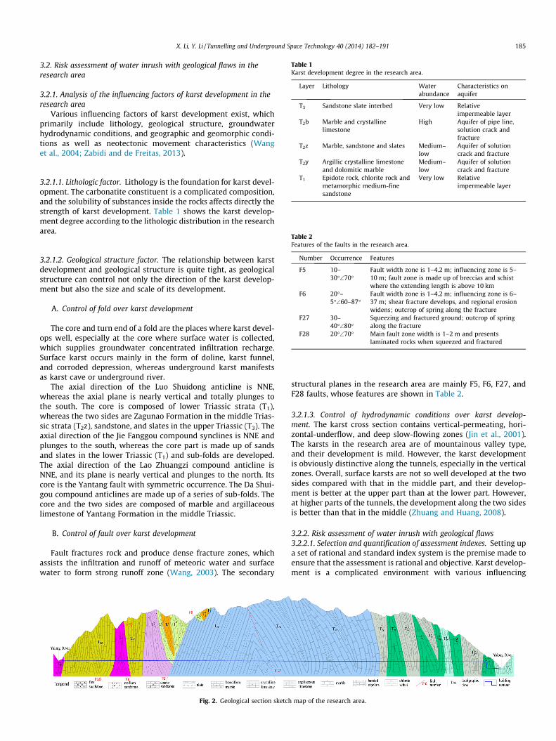
Table 1Karst development degree in the research area.
Layer Lithology Waterabundance
Characteristics onaquifer
T3 Sandstone slate interbed Very low Relativeimpermeable layer
T2b Marble and crystallinelimestone
High Aquifer of pipe line,solution crack andfracture
T2z Marble, sandstone and slates Medium–low
Aquifer of solutioncrack and fracture
X. Li, Y. Li / Tunnelling and Underground Space Technology 40 (2014) 182–191 185
3.2. Risk assessment of water inrush with geological flaws in theresearch area
3.2.1. Analysis of the influencing factors of karst development in theresearch area
Various influencing factors of karst development exist, whichprimarily include lithology, geological structure, groundwaterhydrodynamic conditions, and geographic and geomorphic condi-tions as well as neotectonic movement characteristics (Wanget al., 2004; Zabidi and de Freitas, 2013).
T2y Argillic crystalline limestoneand dolomitic marble
Medium–low
Aquifer of solutioncrack and fracture
T1 Epidote rock, chlorite rock andmetamorphic medium-finesandstone
Very low Relativeimpermeable layer
3.2.1.1. Lithologic factor. Lithology is the foundation for karst devel-opment. The carbonatite constituent is a complicated composition,and the solubility of substances inside the rocks affects directly thestrength of karst development. Table 1 shows the karst develop-ment degree according to the lithologic distribution in the researcharea.
Table 2Features of the faults in the research area.
Number Occurrence Features
F5 10–30�\70�
Fault width zone is 1–4.2 m; influencing zone is 5–10 m; fault zone is made up of breccias and schistwhere the extending length is above 10 km
F6 20�–5�\60–87�
Fault width zone is 1–4.2 m; influencing zone is 6–37 m; shear fracture develops, and regional erosionwidens; outcrop of spring along the fracture
F27 30–40�\80�
Squeezing and fractured ground; outcrop of springalong the fracture
F28 20�\70� Main fault zone width is 1–2 m and presentslaminated rocks when squeezed and fractured
3.2.1.2. Geological structure factor. The relationship between karstdevelopment and geological structure is quite tight, as geologicalstructure can control not only the direction of the karst develop-ment but also the size and scale of its development.
A. Control of fold over karst development
The core and turn end of a fold are the places where karst devel-ops well, especially at the core where surface water is collected,which supplies groundwater concentrated infiltration recharge.Surface karst occurs mainly in the form of doline, karst funnel,and corroded depression, whereas underground karst manifestsas karst cave or underground river.
The axial direction of the Luo Shuidong anticline is NNE,whereas the axial plane is nearly vertical and totally plunges tothe south. The core is composed of lower Triassic strata (T1),whereas the two sides are Zagunao Formation in the middle Trias-sic strata (T2z), sandstone, and slates in the upper Triassic (T3). Theaxial direction of the Jie Fanggou compound synclines is NNE andplunges to the south, whereas the core part is made up of sandsand slates in the lower Triassic (T1) and sub-folds are developed.The axial direction of the Lao Zhuangzi compound anticline isNNE, and its plane is nearly vertical and plunges to the north. Itscore is the Yantang fault with symmetric occurrence. The Da Shui-gou compound anticlines are made up of a series of sub-folds. Thecore and the two sides are composed of marble and argillaceouslimestone of Yantang Formation in the middle Triassic.
B. Control of fault over karst development
Fault fractures rock and produce dense fracture zones, whichassists the infiltration and runoff of meteoric water and surfacewater to form strong runoff zone (Wang, 2003). The secondary
Fig. 2. Geological section sketch
structural planes in the research area are mainly F5, F6, F27, andF28 faults, whose features are shown in Table 2.
3.2.1.3. Control of hydrodynamic conditions over karst develop-ment. The karst cross section contains vertical-permeating, hori-zontal-underflow, and deep slow-flowing zones (Jin et al., 2001).The karsts in the research area are of mountainous valley type,and their development is mild. However, the karst developmentis obviously distinctive along the tunnels, especially in the verticalzones. Overall, surface karsts are not so well developed at the twosides compared with that in the middle part, and their develop-ment is better at the upper part than at the lower part. However,at higher parts of the tunnels, the development along the two sidesis better than that in the middle (Zhuang and Huang, 2008).
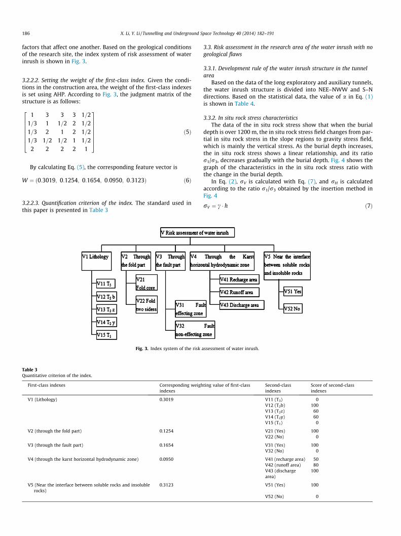
3.2.2. Risk assessment of water inrush with geological flaws3.2.2.1. Selection and quantification of assessment indexes. Setting upa set of rational and standard index system is the premise made toensure that the assessment is rational and objective. Karst develop-ment is a complicated environment with various influencing
map of the research area.
186 X. Li, Y. Li / Tunnelling and Underground Space Technology 40 (2014) 182–191
factors that affect one another. Based on the geological conditionsof the research site, the index system of risk assessment of waterinrush is shown in Fig. 3.
3.2.2.2. Setting the weight of the first-class index. Given the condi-tions in the construction area, the weight of the first-class indexesis set using AHP. According to Fig. 3, the judgment matrix of thestructure is as follows:
1 3 3 3 1=21=3 1 1=2 2 1=21=3 2 1 2 1=21=3 1=2 1=2 1 1=2
2 2 2 2 1
26666664
37777775
ð5Þ
By calculating Eq. (5), the corresponding feature vector is
W ¼ ð0:3019; 0:1254; 0:1654; 0:0950; 0:3123Þ ð6Þ
3.2.2.3. Quantification criterion of the index. The standard used inthis paper is presented in Table 3
Fig. 3. Index system of the risk a
Table 3Quantitative criterion of the index.
First-class indexes Corresponding weighindexes
V1 (Lithology) 0.3019
V2 (through the fold part) 0.1254
V3 (through the fault part) 0.1654
V4 (through the karst horizontal hydrodynamic zone) 0.0950
V5 (Near the interface between soluble rocks and insolublerocks)
0.3123
3.3. Risk assessment in the research area of the water inrush with nogeological flaws
3.3.1. Development rule of the water inrush structure in the tunnelarea
Based on the data of the long exploratory and auxiliary tunnels,the water inrush structure is divided into NEE–NWW and S–Ndirections. Based on the statistical data, the value of a in Eq. (1)is shown in Table 4.
3.3.2. In situ rock stress characteristicsThe data of the in situ rock stress show that when the burial
depth is over 1200 m, the in situ rock stress field changes from par-tial in situ rock stress in the slope regions to gravity stress field,which is mainly the vertical stress. As the burial depth increases,the in situ rock stress shows a linear relationship, and its ratior1/r3, decreases gradually with the burial depth. Fig. 4 shows thegraph of the characteristics in the in situ rock stress ratio withthe change in the burial depth.
In Eq. (2), rV is calculated with Eq. (7), and rH is calculatedaccording to the ratio r1/r3 obtained by the insertion method inFig. 4
rV ¼ c � h ð7Þ
ssessment of water inrush.
ting value of first-class Second-classindexes
Score of second-classindexes
V11 (T3) 0V12 (T2b) 100V13 (T2z) 60V14 (T2y) 60V15 (T1) 0
V21 (Yes) 100V22 (No) 0
V31 (Yes) 100V32 (No) 0
V41 (recharge area) 50V42 (runoff area) 80V43 (dischargearea)
100
V51 (Yes) 100
V52 (No) 0

Table 4Water inrush structure occurrences and the value of a.
Water inrush structureoccurrences
Value of a(�)
344�\77� 71285�\81� 62193�\76� 75255�\89� 89
Where a is the dip angle that exposes the detrimentalstructural plane in the tunnel.
Fig. 4. Graph of the characteristics in the in situ rock stress ratio with the change inthe burial depth.
X. Li, Y. Li / Tunnelling and Underground Space Technology 40 (2014) 182–191 187
where c is the volume weight of the rock, and its specific value isshown in Table 5. h is the burial depth at the tunnel’s calculationpoint.
3.3.3. Selection of parametersBased on the original rock-test results, indoor test materials,
and test results of the rocks with the same lithology, the mechan-
Table 5Physical and mechanical parameters of the rock mass.
Rockcategory
Bulk density (g/cm3)
Cohesion (C)(MPa)
Friction angle (U)(�)
T3 2.69 12 46T2b5 2.61 16 40T2b3 2.63 22 53T2b2 2.65 22 53T2z4 2.64 10 40T2z3 2.64 22 53T2z2 2.66 22 53T2y6–4 2.68 10 39T2y6–3 2.67 20 50T2y5–4 2.64 10 39T2y5–3 2.72 20 50T2y5–2 2.68 22 52T2y4–4 2.78 9.7 39T2y4–3 2.78 19 49T2y4–2 2.78 22 51T1 2.61 14 46
Table 6Mechanical parameters of structural plane.
Structural plane of water inrushoccurrence
Cohesion (C)(MPa)
Friction angle (U)(�)
344�\77� 0.06 18285�\81� 0.1 18193�\76� 0.08 18255�\89� 0.03 16
ical parameters of the rock mass can be set. Tables 5 and 6 showthe parameters used in this paper.
3.3.4. Partition of the assessment unitsThe Diversion Tunnel Groups has been divided into 1680 sec-
tions along the tunnel axis from east to west at an interval of10 m. The division of the cross sections is shown in Fig. 5, wherethe blue units in the figure indicate the units that surround thetunnel.
4. Risk assessment system of water inrush in tunnels
4.1. Methods of combining GIS with specialized models
Until the present, most GIS software has spatial analysis func-tions and attributive data statistics that can meet the needs insome fields to manage and analyze data, but they have not beenso practical in comprehensive and complicated fields. Differentfields have different requirements in terms of data analysisand processing; thus, conducting data processing, informationmanagement, spatial analysis, inversion prediction, and deci-sion-making support by combining GIS with specialized modelsbecomes an important study orientation. Several ways are avail-able to combine GIS with specialized models, namely, loosecombination based on data transmission, seamless surface com-bination based on common interface, embedding specializedmodels in GIS, and embedding GIS functional units into special-ized models.
The combination method for the GIS and risk assessment ofwater inrush usually uses the method of compactness combinationby embedding the specialized model into GIS. The realizationmethod is as follows: on the GIS platform, the risk assessment ofwater inrush model is developed.
4.2. System requirements analysis
Water inrush in tunnels is one of common geological disastersduring the construction and operation of karst tunnel. It dose greatharm to the safety of tunnel construction and affect constructionprogress. If this kind of disaster cannot be dealt with, the operationand earth surface environment will become worse. Therefore, it issignificant to conduct more research on this field to take efficientmeasures to prevent the disaster and make sure the safe construc-tion and operation of tunnels.
One of noticeable features of tunnel construction information isthat a great number of various data come from multiple sources.The second feature is that the information is in line with geo-graphic position and time. The traditional database technologyhas not provided the way to describe and analyze these data. How-ever, the development of GIS offers one way. After survey and anal-ysis, a risk assessment system of water inrush in tunnels can be setup to meet the need of constructions. Built on basic information ontunnels and on construction, this system is characterized by com-prehensive analysis, theme orientation, standard code systems andprocessing ways and intense integration.
4.3. System total design
4.3.1. System targetThe GIS-based water inrush karst-tunnel assessment system is a
water inrush model-centered software system based on dynamicmonitoring data using GIS technique support to realize preciseconstruction forecast. The specific goals are as follows:
(1) To realize the management of tunnel information, includingbasic tunnel and dynamic monitoring information.

Fig. 5. Cross sections of the tunnels.
188 X. Li, Y. Li / Tunnelling and Underground Space Technology 40 (2014) 182–191
(2) To predict water inrush in tunnels and to realize dynamicassessment of water inrush based on constructioninformation.
4.3.2. System environment selectionMAPGIS geographical information system is an instrumental
GIS developed by China University of Geosciences (Wuhan). It isnot only mature basic GIS software but also useful user-devel-oped GIS tool orienting to specific field. MAPGIS can provide com-plete secondary development library and secondary developmentinterface, generally called API (Application Program Interface)which is a set of functional command collection for applicationprogram to call. By the interface functions, user can establish ap-plied GIS orienting to specific field under programming environ-ments including BORLAND C++, VISUAL C++, and VISUAL BASIC.In addition, secondary development library of MAPGIS also pro-vides multiple reusable base classes to developers based onMFC that it packages common basic functions necessary to appli-cation program which enables development to be more conve-nient and flexible.
MAPGIS software and secondary development library were se-lected and used as the base and development platform in thisstudy, and Visual C ++ was used as development environment.
Table 7Classification criteria of the risk of water inrush with geological flaw.
Rank AHP classification criteria Color
Low risk <40 GreenMedium risk 40–60 YellowHigh risk 60–71 RedExtremely high risk >71 Purple
Fig. 6. Partial zoning map of the wate
4.3.3. System function designThe automatic process of inputting and outputting data has
been realized, as presented in the previous sections. The modelfunctions included in this paper are as follows:
A. Data input and output functions
These functions realize the geological construction data, intro-duce them into the system, and obtain the assessment results.
B. Data query function
The graph-to-data and data-to-graph query functions are real-ized based on the forecast database of tunnel water inrush.
C. Forecast function of the danger of water inrush in tunnels
The danger calculation of water inrush in tunnels is realized bythis function with the support of background database from thewater inrush evaluation.
D. Assessment result display function
Classification of the danger of water inrush is processed by thisfunction.
4.3.4. Design of the database
A. Spatial database design
The system data are classified according to the following: eco-logical locations, administrative division, geography, formationlithology, geological structure, hydrogeological conditions, andtunnel data.
r inrush risk in the research area.
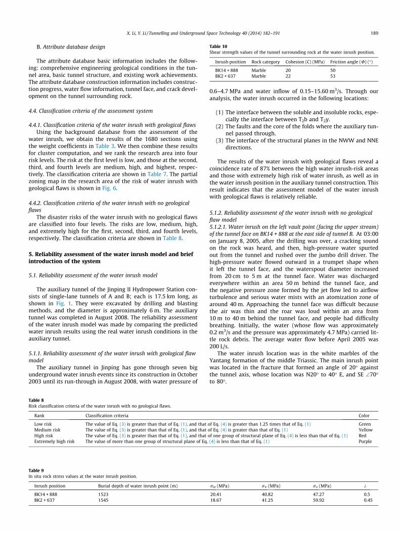
Table 10Shear strength values of the tunnel surrounding rock at the water inrush position.
Inrush position Rock category Cohesion (C) (MPa) Friction angle (U) (�)
BK14 + 888 Marble 20 50BK2 + 637 Marble 22 53
X. Li, Y. Li / Tunnelling and Underground Space Technology 40 (2014) 182–191 189
B. Attribute database design
The attribute database basic information includes the follow-ing: comprehensive engineering geological conditions in the tun-nel area, basic tunnel structure, and existing work achievements.The attribute database construction information includes construc-tion progress, water flow information, tunnel face, and crack devel-opment on the tunnel surrounding rock.
4.4. Classification criteria of the assessment system
4.4.1. Classification criteria of the water inrush with geological flawsUsing the background database from the assessment of the
water inrush, we obtain the results of the 1680 sections usingthe weight coefficients in Table 3. We then combine these resultsfor cluster computation, and we rank the research area into fourrisk levels. The risk at the first level is low, and those at the second,third, and fourth levels are medium, high, and highest, respec-tively. The classification criteria are shown in Table 7. The partialzoning map in the research area of the risk of water inrush withgeological flaws is shown in Fig. 6.
4.4.2. Classification criteria of the water inrush with no geologicalflaws
The disaster risks of the water inrush with no geological flawsare classified into four levels. The risks are low, medium, high,and extremely high for the first, second, third, and fourth levels,respectively. The classification criteria are shown in Table 8.
5. Reliability assessment of the water inrush model and briefintroduction of the system
5.1. Reliability assessment of the water inrush model
The auxiliary tunnel of the Jinping II Hydropower Station con-sists of single-lane tunnels of A and B; each is 17.5 km long, asshown in Fig. 1. They were excavated by drilling and blastingmethods, and the diameter is approximately 6 m. The auxiliarytunnel was completed in August 2008. The reliability assessmentof the water inrush model was made by comparing the predictedwater inrush results using the real water inrush conditions in theauxiliary tunnel.
5.1.1. Reliability assessment of the water inrush with geological flawmodel
The auxiliary tunnel in Jinping has gone through seven bigunderground water inrush events since its construction in October2003 until its run-through in August 2008, with water pressure of
Table 8Risk classification criteria of the water inrush with no geological flaws.
Rank Classification criteria
Low risk The value of Eq. (3) is greater than that of Eq. (1), and that oMedium risk The value of Eq. (3) is greater than that of Eq. (1), and that oHigh risk The value of Eq. (3) is greater than that of Eq. (1), and that oExtremely high risk The value of more than one group of structural plane of Eq.
Table 9In situ rock stress values at the water inrush position.
Inrush position Burial depth of water inrush point (m)
BK14 + 888 1523BK2 + 637 1545
0.6–4.7 MPa and water inflow of 0.15–15.60 m3/s. Through ouranalysis, the water inrush occurred in the following locations:
(1) The interface between the soluble and insoluble rocks, espe-cially the interface between T2b and T2y.
(2) The faults and the core of the folds where the auxiliary tun-nel passed through.
(3) The interface of the structural planes in the NWW and NNEdirections.
The results of the water inrush with geological flaws reveal acoincidence rate of 87% between the high water inrush-risk areasand those with extremely high risk of water inrush, as well as inthe water inrush position in the auxiliary tunnel construction. Thisresult indicates that the assessment model of the water inrushwith geological flaws is relatively reliable.
5.1.2. Reliability assessment of the water inrush with no geologicalflaw model5.1.2.1. Water inrush on the left vault point (facing the upper stream)of the tunnel face on BK14 + 888 at the east side of tunnel B. At 03:00on January 8, 2005, after the drilling was over, a cracking soundon the rock was heard, and then, high-pressure water spurtedout from the tunnel and rushed over the jumbo drill driver. Thehigh-pressure water flowed outward in a trumpet shape whenit left the tunnel face, and the waterspout diameter increasedfrom 20 cm to 5 m at the tunnel face. Water was dischargedeverywhere within an area 50 m behind the tunnel face, andthe negative pressure zone formed by the jet flow led to airflowturbulence and serious water mists with an atomization zone ofaround 40 m. Approaching the tunnel face was difficult becausethe air was thin and the roar was loud within an area from10 m to 40 m behind the tunnel face, and people had difficultybreathing. Initially, the water (whose flow was approximately0.2 m3/s and the pressure was approximately 4.7 MPa) carried lit-tle rock debris. The average water flow before April 2005 was200 L/s.
The water inrush location was in the white marbles of theYantang formation of the middle Triassic. The main inrush pointwas located in the fracture that formed an angle of 20� againstthe tunnel axis, whose location was N20� to 40� E, and SE \70�to 80�.
Color
f Eq. (4) is greater than 1.25 times that of Eq. (1) Greenf Eq. (4) is greater than that of Eq. (1) Yellowf one group of structural plane of Eq. (4) is less than that of Eq. (1) Red(4) is less than that of Eq. (1) Purple
rH (MPa) rV (MPa) rh (MPa) k
20.41 40.82 47.27 0.518.67 41.25 59.92 0.45

Table 11Mechanical parameters of the structural plane at the water inrush position.
Water inrush position Structural plane category Structural plane occurrence Value of a (�) Cohesion (C) (MPa) Friction angle (U) (�)
BK14 + 888 Opening, filling N20� to 40� E, SE\70� to 80� 70 0.1 18BK2 + 637 Opening, filling E–W, S\75� to 85� 75 0.1 18
Where a is the dip angle that exposes the detrimental structural plane in the tunnel.
Table 12Calculated results at the water inrush position.
Inrush position Results of Eq. (1) (MPa) rh�cosa�sinða�uÞcosu
Results of Eq. (3) (MPa) r tan Uþ C Results of Eq. (4) (MPa) r tan Uj þ Cj
BK14 + 888 13.40 68.65 13.36BK2 + 637 13.68 76.74 13.50
Fig. 8. Zoning plan of the danger of water inrush disaster.
190 X. Li, Y. Li / Tunnelling and Underground Space Technology 40 (2014) 182–191
5.1.2.2. Water inrush at the right bottom point (facing downstream) ofthe tunnel face on BK2 + 637 in the west side of tunnel B. On April 20,2005, at 22:20, approximately 10 h after the blasting and themucking process, a huge water inrush occurred. The spearheadwater reached the tunnel entrance at 23:00, and the inflow reachedits largest volume at 23:30 with a flow of 15.6 m3/s. Starting at00:00 on April 21, 2005, the flow decreased rapidly.
The water inrush point was located in the white and flesh-redmarbles of the Zagunao formation in the middle Triassic. The waterinrush point was in the fracture and crush belt at an interval of0.03–30 cm at the E–W and S\75� to 85� location. The funnel-shaped mouth whose depth was 2.5 m was fractured by high-pres-sure water. Its height was 0.8 m from the tunnel bottom, its lengthwas 1.8 m along the tunnel axis, and its depth was approximately0.6 m along the vertical of the tunnel surrounding rock.
The in situ rock stress values at the water inrush position areshown in Table 9. The shear strength values of the tunnel sur-rounding rock are shown in Table 10. The mechanical parametersof the structural plane at the inrush position are shown in Table 11.The calculated results are shown in Table 12.
The results of Table 12 show that BK14 + 888 and BK2 + 637have been estimated high risk rank of water inrush according toTable 8. The conclusion accords with construction situation. As asummary, with a relatively high reliability, the assessment modelcan be applied in the risk assessment of water inrush in the Diver-sion Tunnel Groups.
Fig. 7. Real-time data input dial
5.2. System overview
The result of water inrush with geological flaws was takenas background, Click on any section when system is running,
og box during construction.

X. Li, Y. Li / Tunnelling and Underground Space Technology 40 (2014) 182–191 191
the system will pop up Zoning plan of the danger of water in-rush disaster with no geological flaws. Fig. 7 shows the real-time data input dialog box during construction provided bythe system. Fig. 8 shows the zoning plan of the danger ofwater inrush disaster in the No. 850 unit forecasted by thesystem.
6. Conclusion
(1) Prediction of the water inrush in the karst tunnel is acomplicated problem that involves many fields such ashydrogeology, engineering geology, construction technol-ogy, and rock mechanics. Establishing assessment mod-els among these fields is of the greatest significance.This paper assesses the risk of the water inrush withgeological flaws in the tunnel by calculating theirweight using AHP based on the analyzed factors thatinfluence the karst development. The risk assessmentof the water inrush with no geological flaws is con-ducted by establishing the assessment models usingrock mass mechanics. The method that combines thetwo assessments above primarily focuses on the engi-neering geological conditions, neglecting the constructiontechnology.
(2) As shown by the results of the assessment of the waterinrush with geological flaws, the extremely high-risk areaof water inrush accounts for 8.99% of the total area, that withhigh risk accounts for 22.98%, that with medium riskaccounts for 47.02%, and that with low-risk accounts for21.01%.
(3) The technical route corrects the calculated results in the sys-tem according to the water data obtained during the con-struction, actual engineering geological conditions after theexcavation, and the calculated results of the dominant jointlocations. With rapid management response and real-timedecision, the technical route well meets the practicalrequirements in construction, providing relatively correctand direct geological basis and engineering technical sup-port for water exploration for the safety of tunnelexcavation.
(4) As their lithology are non-karst rock, the assessment resultsof T1 section and T3 section only possess reference meaningon construction.
Note
T1 and T3 are non-carbonate rocks. Although T1 section and T3
section in the tunnels are calculated by system, its evaluation re-sults assignment for low risk area in the system.
Acknowledgements
The support from the Chinese National Natural Science Founda-tion (No. 50579089) and Wuhan Science and Technology BureauKey Scientific and Technological Project (No. 201160823267) areacknowledged.
References
Ge, Y.H., Li, Sh.C., Zhang, Q.S., Li, L.P., Liu, B., 2010. Comprehensive geologicalprediction based on risk evaluation during tunneling in karst area. GeotechnicalEngineering 7 (32), 1124–1130 (in Chinese).
Huang, M., Jiang, Y.J., Liu, X.R., Guan, Z.C., Yu, J., 2012. Study on the water burstcharacteristics and risk aversion in water-enriched karst tunnel with highhydraulic pressure. Disaster Advances 5 (4), 1680–1685.
Jiang, D., Wang, J.H., Chen, P.P., Yang, M.G., 1999. Forecasting of water inrush in coalmine by artificial neural network. Catastrophology 14 (1), 28–32 (in Chinese).
Jin, Zh.K., Zou, Y.R., Jiang, Ch.L., You, W.F., 2001. Distribution and controlling factorsof ordovician karst reservoirs in dagang region. Acta Sedimentologica Sinica 19(4), 530–535 (in Chinese).
Li, F.F, 2006. Study on Mechanism and Forecast of Water Outbrush and MudOutbrush of Jin-ping Tunnel, M.A. Sc. Thesis. Southwest Jiaotong University,Chengdu, Sichuan, 39p.
Li, L.P., 2009. Study on Catastrophe Evolution Mechanism of Karst Water Inrush,PhD Thesis. Shandong University, Jinan, Shandong, 10p.
Li, L.P., Li, Sh.C., Chen, J., Li, J.L., Xu, Zh.H., Shi, Sh.Sh., 2011. Construction licensemechanism and its application based on karst water inrush risk evaluation.Rock Mechanics and Engineering 30 (7), 1345–1355 (in Chinese).
Liu, Zh.W., He, M.Ch., Wang, Sh.R., 2006. Karst inrush water mechanism and preventioncountermeasure study. Rock and Soil Mechanics 2 (2), 228–246 (in Chinese).
Ma, Sh.W., Mei, Zh.R., 2009. Geology structure quantization evaluation andmonitoring warning. Modern Tunneling Technology 2, 99–104 (in Chinese).
Mao, B.Y., Xu, M., Jiang, L.W., 2009. Preliminary study on risk assessment of waterand mud inrush in karst tunnel. Carsologica Sinica 29, 183–189 (in Chinese).
Saaty, T.L., 1977. A scaling method for priorities in hierarchical structures.Mathematical Psychology 15 (3), 234–281.
Shan, Zh.G., 2009. Macrocopic geological forecast and verification of karstdevelopment intensity in deep-lying tunnels of Jinping II project. Journal ofShandong University (Engineering Science) 39 (S2), 96–98, 114 (in Chinese).
Shen, X.M., Liu, P.L., Wang, J.F., 2010. Evaluation of water-inrush risks of karsttunnel with analytic hierarchy process. Railway Engineering Society 12, 56–63(in Chinese).
Shi, L.Q., Singh, R.N., 2001. Study of mine water inrush from floor strata throughfaults. Mine Water and the Environment 20 (3), 140–147.
Wang, Y., 2003. Classification of karst water systems in karst down-faulted basins ofthe southwestern China karst region. Geology in China 30 (2), 220–224 (inChinese).
Wang, Y., Chen, Q., Wei, Y.Y., Chen, L., 2004. Water/rock interaction mechanism indeep-buried tunnels in karst area. China Railway Science 25 (4), 55–58 (inChinese).
Wu, Sh.Y., Wang, J., Wang, G., 2007. Underground water and its treatment strategyin auxiliary tunnels of Jinping hydropower project. Rock Mechanics andEngineering 26 (10), 1959–1967 (in Chinese).
Wu, Q., Xu, H., Pang, W., 2008a. GIS and ANN coupling model: an innovativeapproach to evaluate vulnerability of karst water inrush in coalmines of northChina. Environmental Geology 54 (5), 937–943.
Wu, X.Zh., Li, M.Ch., Wu, Y.T., 2008b. Analysis and prevention measures for rockburst in the auxiliary tunnel of the Jinping Hydropower Station. Journal ofShandong University (Engineering science) 38 (3), 28–33 (in Chinese).
Zabidi, H., de Freitas, M.H., 2013. Geospatial analysis in identifying karst cavitydistribution: The SMART Tunnel, Malaysia. Carbonates and Evaporites 28 (1–2),125–133.
Zhuang, J.Y., Huang, Y.L., 2008. Discussion on impact factor of karst. West-ChinaExploration Engineering (in Chinese) 1, 127–128.