research memorandum - digital library/67531/metadc61612/m2/1/high... · research memorandum . ......
TRANSCRIPT

R"L55F22
RESEARCH MEMORANDUM .
SOME DESIGN IMPLICATIONS OF THE EFFECTS
OF AERODYNAMIC HEATING
By Richard R. Heldenfels
Langley Aeronautical Laboratory Langley Field, Va.
CIMSIFIED DOCUMENT
This material contains information affecung the National Defense of the United States within the meaning of the espionage laws, Title 18, U.S.C., Secs. 793 and 794, the transmission or revelation of which in any manner to 811 unauthorized person is prohibited by law.
NATIONAL ADVISORY COMMITTEE FOR AERONA,UTICS
WASHINGTON July 28,1955
NACA RM L'3'3F22 !j
NATIONAL ADVISORY COMMITTEE FOR BONAUTICS
RESEARCH MEMORANDlM
SOME DESIGN IMPLICATIONS OF TRE EFFECTS
OF AEEODYNAMIC HEATING
By Richard R. Heldenfels
SUMMARY
The structural design problems created by aerodynamic heating appear t o be numerous, complex, and very severe. Two of these problems, creep and thermal buckling, are examined to ind ica te the i r e f fec t on the design of s t ructures for high-speed aircraft; then consideration is given to t he use of insulation as a means of a l leviat ing the effects of aerodynamic heating. The resu l t s show that creep may not be a s ignif icant factor , but thermal buckling may have a substant ia l effect on the s t ruc tura l design. The use of insulation has merit under certain conditions but poses many new design problems. These r e su l t s axe based on limited data and may change as more information becomes available.
INTRODUCTION
Many papers in the recent l i t e ra ture ( for example, re fs . 1 t o 8) have discussed the various structural effects of aerodynamic heating. These papers have made it clear that the resul t ing s t ructural design problems are numerous, complex, and so severe that the performance capa- b i l i t i e s of high-speed a i r c ra f t may be great ly res t r ic ted. A more opti- mistic view of the situation, however, indicates that the severity of most of these problems i s often overemphasized. The purpose of this paper i s to take a br ief look a t the effect of two problems, creep and thermal buckling, on the design of a i rcraf t s t ructures and t o give some consideration to the use of insulation as a means of a l leviat ing the e f fec ts of aerodynamic heating.
The symbols used are defined in appendix A.
2
CREEP
NACA RM L’35F22
The creep of aircraft structures.at elevated temperature is often assumed t o be a very important problem. Its importance, however, has not been established, and before accepting it as a major problem, i t s significance in aircraft design should be examined.
Creep is a primary design criterion in much high-temperature machin- ery, such as heat exchangers and gas turbines, but in this type of equip- ment the material must withstand the combined design temperatures and loads for long periods of time. The usua l a i rc raf t s t ruc ture on the other hand i s subjected t o a var ie ty of loads that occur under varying temper- ature conditions.
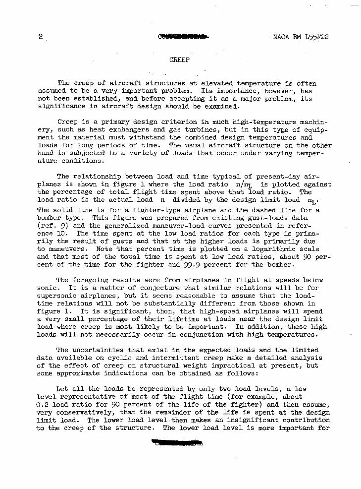
The relationship between load and time typica l of present-day air- planes i s shown i n f i w e 1 where the load r a t i o n/nL is plotted against the percentage of t o t a l f l i g h t time spent above that load ra t io . The load ra t io i s the actual load n divided by the design l i m i t load nL. The so l id l ine is f o r a fighter-type airplane and the dashed l i ne fo r a bomber type. This f igure was prepared from existing gust-loads data ( r e f . 9) and the generalized maneuver-load curves presented i n refer- ence 10. The time spent at the low load r a t io s fo r each type i s prima- r i l y t h e r e s u l t of gusts and that at the higher loads is primarily due t o maneuvers. Note that percent tlme i s plot ted on a logarithmic scale and that most of t h e t o t a l time i s spent at low load ra t ios , about 90 per- cent of the t ime for the f ighter and 99.9 percent for the bomber.
The foregoing results were from a i rp lanes in f l igh t a t speeds below sonic. It i s a matter of conjecture w h a t similar relat ions w i l l be for supersonic airplanes, but it seems reasonable t o assume tha t the load- time relat ions will not be substant ia l ly different from those shown i n figure 1. It is significant, then, tha t high-speed airplanes will spend a very small percentage of their l ifetime at loads near the design limit load where creep is most l i k e l y t o be important. In addition, these high loads w i l l not necessarily occur in conjunction w i t h high temperatures.
The uncertainties that e x i s t i n . t h e expected loads and the l imited data available on cyclic and intermittent creep make a detailed analysis of the effect of creep on s t ruc tura l weight impractical at present, but some approximate indications can be obtained as follows:
L e t a l l t h e loads be represented by only two load levels, a low level representative of most of t he f l i gh t time ( fo r example, about 0.2 load ra t io for 90 percent of t h e l i f e of the f igh ter ) and then assume, very conservatively, tha t the remainder of t h e l i f e is spent at the design l i m i t load. The lower load 1evel.then makes an insignificant contribution to the creep of the s t ructure . The lower load level is more important for

NACA RM L55F22 3
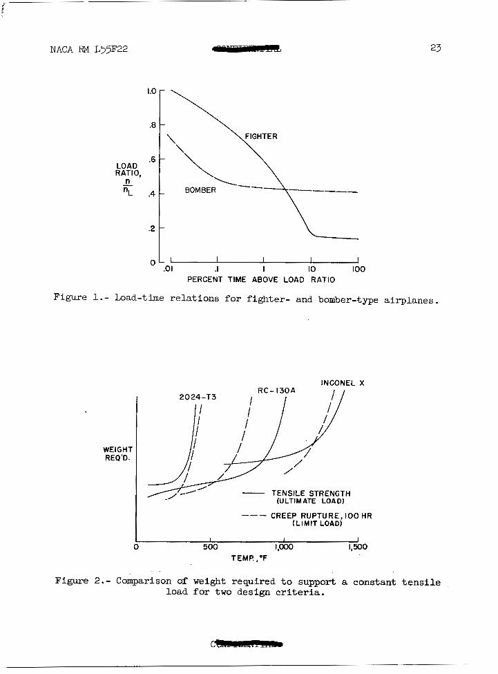
the bomber than for the f ighter because it i s a large percentage of the design load and because the bomber would have a longer expected lifetime, but s t i l l t h e lower load ra t io makes only a small contribution. For either case, the effect of creep on s t ruc tura l weight can be estimated very conservatively by fixing a lifetime of 100 hours a t temperature and l i m i t load combined. Results of such an analysis are shown in f igure 2 where the weight required to support a given constant tensile load i s plotted against temperature for three structural materials and fo r two design cr i ter ia . The solid curves indicate the weight required when the c r i te r ion i s the ult imate tensile strength; the dashed l ines give the weight required when creep rupture a t limit load i s used. The three materials selected for this analysis, 2024-T3 (2&-T3) aluminum alloy, RC-130A titanium alloy, and Inconel X, cover the temperature range i n which metals are usable. The s ta in less s tee l s genera l ly fa l l between RC-130A and Inconel X, but nearer RC- lWA.
Consider f i r s t t h e aluminum alloy. The weight required to support
the load on the basis of ult imate tensile strength 1- times the design
l i m i t load i s given by the so l id l ine . The weight required to meet the creep cri terion - f a i lu re a f t e r 100 hours a t temperature and limit load - i s given by the dashed line. Since the creep criterion requires less weight than the strength criterion throughout the temperature range of the aluminum alloy, creep i s not a design problem for this mater ia l . A similar s i tuat ion exis ts for InconelX for most of the temperature range, but for temperatures above 1,2000 F creep requires more weight than ultimate strength. Creep thus becomes important for Inconel X structures only in the temperature range where strength i s decreasing rapidly with increasing temperature. For the titanium alloy, creep becomes a design problem a t temperatures above 500° F. Note tha t above the temperature where creep becomes important, the weight required by the creep criterion increases rapidly with temperature, and design effi- ciency would best be obtained by conversion t o a material for which creep would not be a problem. This particular titanium alloy has poor creep characterist ics; others are better in creep than RC-lWA, but they have
. less tensile strength. Further development of titanium alloys will prob- ably improve th i s s i tua t ion .
1 2
Since the creep cri terion used in this analysis usually required l e s s weight than the ultimate-strength criterion, it appears that creep may have l i t t l e e f f e c t on aircraft structural design. I n those cases where creep is a significant factor, conversion to another material w i l l be desirable in the interest of s t ructural eff ic iency and the task of designing for creep w i l l be avoided. The results presented were obtained w2th a very conservative estimate of the load-temperature-time experience of the s t ructure . I f something less than 100 hours had been used f o r the lifetime, creep would appear t o be even l e s s important.

4 NACA RM . L55F22
The-importance of creep is also influenced by the type of creep criterion used, and other factors such as the perma.Qent deformations due t o creep and the e f f ec t of creep on ultimate strength should be con- sidered, but indications are that these w i l l be secondary design consid- erations. Creep f a i lu re was used as a ,design cr i ter ion in . th is analysis because of i t s obvious significance. A prescribed amount of permanent creep deformation could have been used, but the validity of such a c r i - ter ion appl ied to an a i rc raf t s t ruc ture is extremely doubtful. This doubt a r i ses from investigations of the creep behavior of aluminum-alloy structural elements and box beams coupled with the expected load- temperature-time experiences of a i rcraf t s t ructures . Creep may also affect the ult imate strength of the structure, but some exploratory tests on aluminum-alloy p la tes and box beams indica te tha t in many cases t h i s e f fec t w i l l be negligible.
To summarize t h e r e m k s on creep, it appears that in general creep may not be a primary factor in the design of high-speed a i r c ra f t because of the character of the relationships between loads, temperatures, and time. Some materials are much more susceptible to creep than others; thus, i n some cases a change in materials may be necessary in order to avoid creep problems.
THEEiMAL BUCKLING
Thermal buckling promises t o be the most serious problem associated with the transient aspects of aerodynamic heating. Thermal buckling has an adverse effect on the bending s t i f fness of beams as shown in re fe r - ence 6, thermal stresses less than those required for buckling reduced the effect ive s t i f fness of a cantilever plate as reported in reference 7, and aerodynamic heating and thermal stresses have i n c i t e d f l u t t e r of some w i n g structures as described in reference 8. The work of reference 8 is now reviewed i n connection w i t h more recent tes ts .
I n a continuation of the research described in reference 8, most models tes ted at Mach number 2 in t he p re f l igh t j e t of the Langley Pi lot less Aircraf t Research S ta t ion a t Wallops Island, Va., experienced no d i f f i cu l t i e s j bu t a few came t o a sudden and violent end. Failure was usually preceded by a new type of f lu t te r , ca l led chordwise f l u t t e r , bu t th i s f lu t te r d id no t begin until the aerodynamic heating had taken effect . Chordwise f l u t t e r involves distortion of the airfoil section
into a mode having about 1I waves along the chord - a flag-waving action.
This f l u t t e r may look l ike panel f lut ter , but the complete cross section is involved rather than individual skin panels.
2

I
i NACA RM L55F22 C. 5
From the f i rs t few t e s t s i n t h i s program, it was concluded tha t f l u t t e r s t a r t ed a f t e r t he model skin buckled. However, i n o the r t e s t s of similar models f l u t t e r was obtained without buckling, and the concept of reduced s t i f fness resul t ing from thermal stresses has been used t o explain these results. For example, a model ident ica l to model MW-1 of reference 8 began t o f l u t t e r without any evidence of buckling and f l u t - t e red for about 6 seconds before the rivets flew out and general destruc- t i o n began. Model MW-4 of reference 8 and an ident ical model tes ted sub- sequently each fluttered and f a i l ed without any indication of buckling. This l a t t e r model had previously survived a t e s t ( a t low stagnation tem- perature) in which it did not experience aerodynamic heating.
From the above it i s evident tha t thermal stresses lower than those required for buckling can induce dangerous aeroelastic effects. This . . s i tua t ion is not so serious as it seems, however, s ince t es t resu l t s show that small changes in the s t i f fness of the wing structure, such as the addition of a r i b o r two, prevented f l u t t e r without much increase in weight. (For example, a model similar t o model MW-4 of r e f . 8 but incor- porating a single r i b midway between t i p and root survived the test con- dit ions without difficulty.) Thus , careful design can prevent many f a i l - ures of the type discussed above. The use of internal construction that minimizes thermal stresses may be required in some cases, but there are a wide variety of f l ight condi t ions in which more conventional designs are sat isfactory.
The f l i g h t regimes i n which m u l t i w e b construction may be sat isfactory can be determined from the conditions tha t produce thermal buckling of the wing skin. Figure 3 shows some combinations of dimensions of a sim- p l i f i e d s t e e l multiweb beam tha t make the structure subject to thermal buckling (thermal stress UT equal to buckling stress Ucr) under sym- metrical aerodynamic heating conditions. The distance between webs (on a logarithmic scale) i s plotted against Mach number for three a l t i tudes (sea level, p , O O O f ee t , and 100,000 f e e t ) . For web spacings above a solid line, thermal buckling of the skin w i l l occur, whereas, below the solid l ine, buckling w i l l not occur.
A low leve l of thermal s t r e s s may be required t o prevent c r i t i c a l changes in aeroelastic characterist ics or to prevent buckling in the presence of wing bending loads. Present knowledge does not permit an estimate of the aeroelastic effects of a given thermal stress dis t r ibu- t i on o r of the level of thermal stress that may be tolerated, but an assungtion that thermal stresses only 10 percent of those required for buckling may be permissible appears t o be reasonable. The dash-line curves give the web spacings corresponding t o t h i s 10-percent condition.
(. , . . I , (
. ,
The web spacings that would .be used f o r an efficient load-carrying structure would be around 2 t o 5 inches; thus such a structure would be i n no danger of buckling due t o heating alone, but a low l eve l of thermal

6 - NACA RM ~ 5 5 ~ 2 2
s t r e s s could not be attained in this structure a t Mach numbers above 3 without very closely spaced webs.
Figure' 3 is based on several approximations (see derivation of equa- t ions in appendix B) and a simplified structure and thus indicates only the approximate combinations of dimensions and f l ight condi t ions that will produce buckling of one ser ies of beams. Similar charts are eas i ly prepared for other configurations, but an actual design should be checked by a more exact analysis.
I n summarizing the remarks on thermal buckling, the present state of knowledge. indicates that thermal buckling should be prevented. I n many cases thermal stresses well below those required for buckling may lead to dangerous aeroelast ic effects . The proper location of internal members may prevent such effects without undue weight penalt ies under many flight conditions, but special types of internal s t ructure that minimize thermal stresses w i l l be necessary when severe aerodynamic heating is encountered.
INSULATION
Having discussed two of the problems resul t ing from aerodynamic heating, consideration i s now given t o one of the ways of a l leviat ing heating effects, namely, insulating the structure. One of the many prob- able uses of insulation is t o extend the aerodynamic-heating conditions under which aluminum alloys are useful structural materials. Figure 4 presents resul ts to show the effect of insulation on the temperature his tory of a 0.10-inch-thick skin of aluminum alloy.
Temperature T is plotted against time in minutes for an instan- taneous acceleration t o a Mach number of 4 a t an a l t i t ude H of 50,OOO f ee t . The temperature history of the uninsulated skin i s shown by the upper so l id l i ne and the effect of 0.1 inch of insulation such as rock wool or asbestos (thermal conductivity of 0 .O3 Btu/ft-hr-OF) i s shown by the lower so l id l ine . The temperature of the outer surface of the insulation i s given by the dashed l ine . The equations used to ca l - culate these curves, and others to be presented i l lustrat ing the effect of insulation, are given in appendix C.
For the f l ight condi t ion used in f igure 4, the aluminum alone would quickly reach a temperature a t which i t s strength had vanished, whereas a re la t ive ly th in l ayer of insulation holds the temperature down fo r sev- e r a l minutes. This i s a very beneficial result insofar as the structure is concerned, bu t th i s benef i t has been obtained by t ransfer r ing d i f f icu l t design problems to the insulat ion. The temperature of the heated surface

NACA RM ~ 3 5 ~ 2 2
of the insulation rises very quickly to a value near the equilibrium temperature Teq (which i s assumed equal to the adiabatic wall temper- ature TAW) and thereaf ter changes very slowly. The insulation must thus withstand high temperatures and lasge temperature differences which will require special design techniques for the construction and attachment of such a protective coating.
The fact that the surface temperature of the insulation closely approximates the equilibrium temperature permits considerable simplifica- t i on of the re la t ion between the insulation required and the f l i gh t con- di t ion. By neglecting the specific heat of the insulation and assuming that the temperature of the outer surface of the insulation i s the equi- librium temperature, a conservative estimate of the required thickness of insulation can be obtained, as shown in f igure 5 (see eq. ( C 7 ) ) . The required thickness i s plotted against surface temperature for 0.10-inch- thick skin of aluminum tha t r i s e s from Oo t o 200° F in the times indicated. Each of the curves i s for a particular value of the time required for the structure to reach 200' F and the thermal conductivity of the insulation i s assumed t o be invariant with temperature. This figure shows tha t high equilibrium temperatures and long f l i g h t times require very thick layers of insulation, thicknesses that are impractical for many par t s of the a i r c ra f t such as thin wings or control surfaces.
The s i tua t ion improves somewhat for heavier structures since the same curves apply to other thicknesses of aluminum skin. For example, if the thickness of the skin i s doubled, the time during which the insula- t ion i s effect ive w i l l also be doubled or the required insulation thick- ness w i l l be cut in half . The required thickness i s substant ia l ly reduced i f the skin is allowed t o go to higher temperatures, but for this case the relationship is not so simple. Higher skin temperatures would neces- s i ta te another s t ructural mater ia l and lead to considerations of struc- tural eff ic iency.
The thicknesses indicated in figure 5 are rather large and somewhat.. discouraging; however, another approach to the insulation problem t h a t can r e s u l t i n lower heat transfer, less thickness, and possibly l ighter weight i s the use of radiation shields.
Average heat transfer through two types of insulators i s shown i n figure 6 as a function of the surface equilibrium temperature. The so l id l ines a re for two thicknesses 2 of the previously discussed bulk insula- t i on such as rock wool or asbestos. The dashed l fnes a re for a single radiat ion shield a t two values of emissivity E. The radiat ion shield, would consist of a thin sheet of metal supported a short distnnce away from the .outer surface of 'the ' structure. The aerodynamic surf ace, of the shield would be a black-body radiator (high emissivity) to keep surface tempera- ture low, but the imier surface of the' shield and outer surface of the' structure would be very bright (low emissivi ty) to minimize radiant heat

8 NACA €M LY7F22
exchange. Some low-conductivity supporting structure, such as a honey- comb core, would be needed between them, but in this analysis , the heat transferred by t h i s supportfng structure and t h e , a i r between shield and structure has been neglected (see appendix C) . The emissivity of 0.1 is about the upper l imi t fo r most shiny metals, but the value of 0.02 can be attained only with special coatings such as gold o r s i lver p la te .
The average heat flow plotted i s the average rate at which the insu- la tors transfer heat to the s t ructure w h i l e the s t ructure rises from Oo t o 200° F. The conditions considered are similar t o those in f igure 5 , but by plot t ing average heat flow, a l l combinations of time and heat capacity of the structural material are included. Where two curves cross, the insulators are exactly equivalent for the conditions considered. A t other points, the lowest curve indicates the best insulator. The curves show that the radiation shield provides excellent protection at the lower temperatures but becomes increasingly inefficient as the temperature increases. The heat flow through the shield can be fur ther reduced by using several of them; f o r example, f ive shields of 0.1 emissivity would t ransfer about the same amount of heat as the single shield of 0.02 emis- sivity, but the added complication of multiple shield arrangements might prove t o be impractical.
A n effective radiation shield requires bright surfaces that are attainable only w i t h metals a% moderate temperatures; thus this approach would probably be limited t o temperatures below about 1,5000 F. Above t h i s temperature, a type of bulk insulation suitable for high-temperature use would be required. For some applications, such as protection of occupants, a combination of insulation, radiation shields, and cooling may provide the most e f f i c i en t combination.
The results presented indicate that insulation provides a suitable way to a l lev ia te the e f fec ts of aerodynamic heating on the primary struc- ture under certain f l ight conditions. This a l leviat ion can be attained, however, only by creation of many d i f f i cu l t problems associated with the design, fabrication, and ins ta l la t ion of the protective coatings.
CONCLUDING RJ3MRKS
The problems of creep and thermal buckling have been discussed in an e f fo r t t o i nd ica t e t he i r e f f ec t s on the design of high-speed aircraft. The resu l t s have shown that creep may not be a s ignif icant factor , but thermal buckling may have a substant ia l effect on the structural design. Consideration has also been given to t he use of insulat ion for the a l levi- a t ion of heating effects; such an approach has merit under cer ta in con- ditions but poses many new design problems.

m " "
1 NACA m ~ 3 5 ~ 2 2 - 9
The results presented are based on the limited existing information on the s t ructural problems of aerodynamic heating. The picture may change as more research results become available, but the design problems undoubt- edly w i l l be eased as knowledge increases. It was not intended to convey the impression tha t aerodynamic-heating problems are easi ly overcome but merely to indicate how careful design can solve some of them.
Langley Aeronautical Laboratory, National Advisory Committee fo r Aeronautics,
Langley Field, Va., June 2, 1955.

10
A
b
C
E
H
h
k
L
2
M
N
n
nL
4
T
t
W
z
U
- A P P ~ I X A
SYMBOLS
cross-sectional area, sq ft
web spacing, ft
specific heat, Btu/lb-OR
modulus of elasticity, lb/sq ft
altitude, ft
heat-transfer coefficient, Btu/ft2-sec-OR
thermal conductivity, Btu/ft-sec-OR
web depth, ft
insulation thickness, ft
Mach number
number of radiation shields
load factor
limit load factor
rate of heat transfer, Btu/ft2-sec
temperature, OR
thickness, ft
specific weight, lb/cu ft
distance along web from center line, ft
coefficient of expansion, ft/ft-OR
NACA RM L55F22

i i NACA RM L55F22 cdllllllll: 11
E emissivity
CI Poisson's ratio
U Stefan-Boltmann constant, Btu/ft -sec-OR4 2
UT thermal stress, lb/sq f t
ucr buckling stress, lb/sq ft
7 time, sec
Subscripts:
AW adiabatic wall
eq equilibrium
i insulation
0 i n i t i a l condition
S skin
W web
A bar over a symbol indicates an average value.
The units given above are those required to keep the equations in appendixes B and C dimensionally correct and do not necessarily apply to the quant i t ies used in the f igures .

12 5" NACA RM L55F22
APPENDIX B
THERMAL BUCKLING OF AERODYNAMICALLY HEATED MULTIWEB BEAMS
For the simplified type of m u l t i w e b construction shown in f igure 3, the maximum compressive stresses (thermal) occur in t he sk in when the wing is subjected to symmetrical aerodynamic heating. The thermal s t r e s ses i n the skin are given by
where T i s the average temperature of the cross section; that is, -
and
Aw = L t ,
The temperature distribution result ing from ins tantaneous accelera- t i o n t o a given flight condition can be obtained from the analysis of reference 11 or 12, but the equations are complex and somewhat d i f f i c u l t t o apply. I n appendix I of reference 2, however, equations for the tem- perature distribution are presented that are a good approximat.ion and are easy t o use since they involve only one parameter in addi t ion to the usual temperature and time parameters. I n t h i s approximate analysis, it is assumed that the skin temperature i s uniform at each instant of time and given by
The web temperature a t z = - follows the above relat ion, and the
temperature distribution in the web is found by solving the equation of 2

NACA RM L55F22
heat conduction. notation changed
The resu l t from appendix I of reference 2 (with the t o t h a t of this paper) i s
r
4 5 R n=l, 3 , 5
nZr2
472
where
The above solution converges if -12 f -. In reference 11, it is
shown that the thermal stresses obtained from t h i s temperature distribu- t i o n agree well with the exact analysis and tha t the resu l t s for an fnstan- taneous acceleration are only slightly conservative when compared with resu l t s for a f ini te accelerat ion.
n2s 2 4
With the above assumptions the uniform thermal s t ress in the sk in is given by
- -Ea( Ts - T,)

14
and
NACA RM L55F22
The thermal stresses vary with time, but those in the skin have a m a x i m u m a t T = 7' when
The maximum temperature difference of equation (6) and the time a t which it occurs have been evaluated as functions of 9 and are plot ted in figure 7.
The thermal stresses given by equation (B5) can now be made any desired fraction of the skin buckling stress. For purposes of t h i s analysis, it is assumed that the following elastic-buckling formula f o r a simply supported plate applies:
The above equation should give satisfactory results in the elastic range, but if thermal buckling occurs at stress levels in the plastic range neither equation (B5) nor (B8) is s t r ic t ly appl icable . There is l i t t l e known about thermal buckling under such conditions; consequently, for the approximate analysis of this report it w i l l be assumed that the elastic analysis applies throughout the s t r e s s range since the errors in equations (B5) and (B8) may compensate one another.

NACA RM L55F22 6mmmmme 15
To obtain the curves in figure 3, heat-transfer coefficients were determined from reference 13 and the following properties of the steel multiweb beams were used:
L = 4 in.
t, = 0.125 in.
l+ = 0.031 in.
CL = 0 .33
a = 7.6 x in./in.-'R
c = 0.11 Btu/lb-OR
w = 500 lb/cu ft
k = 8.5 Btu/ft-hr-OR

16
APPENDIX c
3 EFFECTS OF INSULATION
NACA RM L55F22
Temperature Histories
If an instantaneous acceleration to a given flight condition is assumed, the temperature of a thin uninsulated metal skin is given by
If the heat capacity of the insulation i s neglected, equation ( C l ) applies to the insulated metal skin if the heat-transfer coefficient is replaced by a value that includes the thermal resistance of the insulation. Thus
Corresponding t o the above results, the temperature of the exposed sur- face of the insulation is given by
where Ts ' varies with time as given by equation ( C 3 ) . Equation ( C 4 ) indicates that when the skin i s well insulated (k/2 is small compared with h) T i i s Very nearly equal to TAW, a f a c t that is used in the
next section. Also, according t o equation (C4), T i starts a t a t e m - perature above t h e i n i t i a l temperature of the system because the heat capacity of insulation was neglected, but an approximate indication of i n i t i a l va r i a t ion of the surface temperature of the insulation can be obtained from

NACA RM L55F22 17
2hr "
Ti' = T i - ( T i - To)e c iwi a
where Ti i s given by equation ((34).
The curves in f igure 4 were calculated by using the above equation and the following numerical values:
For aerodynamic heating,
To = -670 F
h = 0.011 Btu/ft2-sec-OR
for the aluminum skin,
c = 0.23 Btu/lb-OR
w = , 173 lb/cu f t
ts = 0.10 in .
and for the insulation,
C i = 0.20 Btu/lb-OR
2 = 0.01 in.
k = 0.030 Btu/ft-hr-OR
Insulation Required . .~ . ,~ . . . . . .. , . , I. . ,
A simple equation for the required thickness of i n su la t ion cm be , ,
obtained by neglecting the heat ,capac.ity of the insulation and assuming

. .
18 n3pprrt NACA RM L55F22
that the temperature of the exposed surface of the insulation is the equilibrium temperature. Then the heat-balance equation
#Teq - Ts) = cwts - k dTl3 ' dT
has the following solution:
The required thickness i s given by
Equation ( ~ 8 ) i s accurate i f the heat capacity of the insulation is small compared with the heat capacity of the metal skin, but it is very con- servative if the heat capacit ies are of the same order of magnitude.
The curves i n f i g u r e 5 were calculated by using equation (C8) and the following numerical values:
To = 0' F
T s = 200' F
k = 0.030 Btu/ft-hr-OR
c = 0.23 Btu/lb-OR
w = 173 lb/Cu f t
ts = 0.10 in .
Radiation Shield
The heat transferred by radiation between two pa ra l l e l plane sur- faces of inf ini te extent i s given by (ref. 14)

If the metallic skin i s protected by N radiation shields that a;re gray-body radiators of emissivity E and the inside surface of the metallic skin has t h i s same emissivity, . then the heat transferred to the structure by radiation is
The time required for the structure to reach a prescribed temperature i s given by the following equation which was obtained by neglecting the heat capacity of the radiation shields and assuming that the s t ructure received heat only by radiation:
where
Average Heat Flow
A convenient way t o compare the bulk type of insulation with the radiation shield is t o consider the average rate of heat transfer during the time T that the skin is rising from the ini t ia l temperature To t o t h e f i n a l temperature Ts. This average rate of heat transfer < is then defined as follows: . : ,

20 NACA m ~ 5 5 ~ 2 2
For the bulk insulation, by using equations (CS) and ( C U ) , the r e su l t i s
and for the radiat ion shields , by using equations ( C 1 1 ) and ( C X ) , the r e su l t is
The curves of figure 6 were calculated by using equations (Cl3) and (C14) and the following numerical values:
To = 0' F
Ts = 200' F
k = 0.030 Btu/ft-hr-'R
d = 0.173 X 10⁻⁸ Btu/ft2-hr-OR
N = 1

NACA F@l L55F22 21
REFERENCES
1. Anon. : Symposium on the Thermal Barrier. Presented by the Aviation Division of the ASME at the annual meeting, Nov. 28 - Dec. 3, 1954.
2. Hoff, N. J.: Structural Problems of Future Aircraft. Third Anglo- American Aeronautical Conference, Brighton, Joan Bradbrooke and E. C. Pike, eds., R.A.S., 1952, pp. 77-114.
3. Hoff, N. J.: The Structural Effects of Aerodynamic Heating. PIBAL Rep. No. 240 (Contract No. AF 33(616) -116), Jan. 1974.
4. Loveless, E., and Boswell, A. C . : The Problem of Thermal Stresses i n Aircraft Structures. Aircraft Engineering, ~ 1 . XXVI, no. 302, Apr. 1954, pp. 122-124.
5. Hibbard, Hall L., and McBrearty, J. F.: Structures for High Speed Aircraft. Aviation Age, vol. 20, no. 5, Nov. 1953, pp. 32-51; Structures for High-speed Flight - 11. Aviation Age, 11-01. 20, no. 6, Dec. 1953, pp. 116-123.
6. Pride, Richard A. : An Investigation of the Effects of Rapid Skin Heating on Box Beams Loaded i n Bending. NACA RM L55Bo3, 1955.
7 . Vosteen, Louis F., and Fuller, Kenneth E.: Behavior of a Cantilever Plate Under Rapid Heating Conditions. NACA FM L ~ ~ E ~ O C , 1955.
9. Press, Harry, Meadows, May T . , and Hadlock, Ivan: Estimates of Prob- abi l i ty Distr ibut ion of Root-Mean-Square Gust Velocity of Atmospheric Turbulence From Operational Gust-Load Data by Random-Process Theory. NACA TN 3362, 1955.
10. Mayer, John P., and Hamer, Harold A. : A Study of Means f o r Ration- alizing Airplane Design Loads. NACA RM L55E13a, 1955.
11. Pukes, E. W.: Transient Thermal Stresses in Wings. Aircraft Engineering, vol. XXV, no. 298, Dee. 1953, pp. 373-378.
12. Pohle, Frederick V., and Oliver, Henry: Temperature Distribution and Thermal Stresses in a Model of a. Supersonic W i n g . Jour. Aero. Sci., vol. 21, no. 1, Jan. 1954, pp. 8-16.

111 I I II I I I I I I l l I I 111 I I I II I l l II I I I I II 111 I I II I I I I
22 " NACA RM L55F22
13. Van Driest, E. R. : Turbulent Boundary Layer i n Compressible Fluids. Jour. Aero. Sci . , vol. ' 18, no. 3, Mar. 1951, pp. 145-160, 216.
14. Jakob, Max, and Hawkins, George A.: .Elements of Heat Transfer and Insulation. Second ed., John Wiley &Sons, Inc., c.1942, 1950, p. 184.
NACA RM ~ 5 3 ~ 2 2
I .o
.8
LOAD RATIO,
-6
n - nL .4
.2
0 .o I . I I IO IO0 PERCENT TIME ABOVE LOAD RATIO
Figure 1.- Load-time relations for fighter- and bomber-type airplanes.
WEIGHT REQ'D.
202' - I 3 0 A
I
- TENSILE STRENGTH
"- CREEP RUPTURE, 100 HR
(ULTIMATE LOAD)
(LIMIT LOAD)
1 0
I I 1 500 4OOo 1,500
TEMP., 'F
Figure 2.- Comparison of weight required t o support a constant tensile load for two design cr i ter ia .

24 NACA RM ~ 5 5 ~ 2 2
100- - - -
-
WEB
b,lN. - SPAGING,IO -
- -
-
I - LI I I I I
0 2 4 6 M
Figure 3 . - Thermal-buckling boundaries f o r a steel multiweb beam.
/""-
T," F
0 I 2 3 TIME , M I N
Figure 4.- Temperature h is tor ies of insulated and uninsulated aluminum at M = 4 and an a l t i tude of 50,000 f e e t .

NACA RM L55F22 CIlllllLlt
Figure 5.- Insulation required to limit the temperature of 0.10-inch aluminum t o a r i s e from 0' to 200' F.
RADIATION SHIELD
BTU FT* - SEC
SURFACE TEMP., OF
Figwe 6.- Comparison of the average heat flow through two types of. insulators .

26 - 't
NACA' RM L55F22
1.0
.8
OR
h r' IO c w t , .4
2
0
I T, - rw
I IO2 lo4
Figure 7.- Chart f o r determining the time and magnitude of the temperature difference that produces maximum thermal stresses fn the sk in of an aerodynamically heated multiweb beam.
NACA - Langley Field, Va.
I I

. . . I
. .