research laboratory gas foil bearing technology advancements for
TRANSCRIPT

Gas Foil Bearing Technology Advancements
for Closed Brayton Cycle Turbines
NASA/TM—2007-214470
January 2007
Samuel A. Howard, Robert J. Bruckner, and Christopher DellaCorte
Glenn Research Center, Cleveland, Ohio
Kevin C. Radil
U.S. Army Research Laboratory, Glenn Research Center, Cleveland, Ohio
ARL–TR–4036
U.S. ARMY
RESEARCH LABORATORY
https://ntrs.nasa.gov/search.jsp?R=20070006848 2019-04-12T01:41:34+00:00Z

NASA STI Program . . . in Profile
Since its founding, NASA has been dedicated to the
advancement of aeronautics and space science. The
NASA Scientific and Technical Information (STI)
program plays a key part in helping NASA maintain
this important role.
The NASA STI Program operates under the auspices
of the Agency Chief Information Officer. It collects,
organizes, provides for archiving, and disseminates
NASA’s STI. The NASA STI program provides access
to the NASA Aeronautics and Space Database and its
public interface, the NASA Technical Reports Server,
thus providing one of the largest collections of
aeronautical and space science STI in the world.
Results are published in both non-NASA channels and
by NASA in the NASA STI Report Series, which
includes the following report types:
• TECHNICAL PUBLICATION. Reports of
completed research or a major significant phase
of research that present the results of NASA
programs and include extensive data or theoretical
analysis. Includes compilations of significant
scientific and technical data and information
deemed to be of continuing reference value.
NASA counterpart of peer-reviewed formal
professional papers but has less stringent
limitations on manuscript length and extent of
graphic presentations.
• TECHNICAL MEMORANDUM. Scientific
and technical findings that are preliminary or
of specialized interest, e.g., quick release
reports, working papers, and bibliographies that
contain minimal annotation. Does not contain
extensive analysis.
• CONTRACTOR REPORT. Scientific and
technical findings by NASA-sponsored
contractors and grantees.
• CONFERENCE PUBLICATION. Collected
papers from scientific and technical
conferences, symposia, seminars, or other
meetings sponsored or cosponsored by NASA.
• SPECIAL PUBLICATION. Scientific,
technical, or historical information from
NASA programs, projects, and missions, often
concerned with subjects having substantial
public interest.
• TECHNICAL TRANSLATION. English-
language translations of foreign scientific and
technical material pertinent to NASA’s mission.
Specialized services also include creating custom
thesauri, building customized databases, organizing
and publishing research results.
For more information about the NASA STI
program, see the following:
• Access the NASA STI program home page at
http://www.sti.nasa.gov
• E-mail your question via the Internet to
• Fax your question to the NASA STI Help Desk
at 301–621–0134
• Telephone the NASA STI Help Desk at
301–621–0390
• Write to:
NASA STI Help Desk
NASA Center for AeroSpace Information
7115 Standard Drive
Hanover, MD 21076–1320

Gas Foil Bearing Technology Advancements
for Closed Brayton Cycle Turbines
NASA/TM—2007-214470
January 2007
National Aeronautics and
Space Administration
Glenn Research Center
Cleveland, Ohio 44135
ARL–TR–4036
U.S. ARMY
RESEARCH LABORATORY
Prepared for the
Space Technology and Applications International Forum (STAIF–2007)
sponsored by the Institute for Space and Nuclear Power Studies at the University of New Mexico
Albuquerque, New Mexico, February 11–15, 2007
Samuel A. Howard, Robert J. Bruckner, and Christopher DellaCorte
Glenn Research Center, Cleveland, Ohio
Kevin C. Radil
U.S. Army Research Laboratory, Glenn Research Center, Cleveland, Ohio

Available from
NASA Center for Aerospace Information
7115 Standard Drive
Hanover, MD 21076–1320
National Technical Information Service
5285 Port Royal Road
Springfield, VA 22161
Available electronically at http://gltrs.grc.nasa.gov
Level of Review: This material has been technically reviewed by technical management.
This report contains preliminary findings,
subject to revision as analysis proceeds.
This report is a preprint of a paper intended for presentation at a conference.
Because changes may be made before formal publication, this preprint is made available
with the understanding that it will not be cited or reproduced without
the permission of the author.
Trade names and trademarks are used in this report for identification
only. Their usage does not constitute an official endorsement,
either expressed or implied, by the National Aeronautics and
Space Administration.

NASA/TM—2007-214470 1
Gas Foil Bearing Technology Advancements for
Closed Brayton Cycle Turbines
Samuel A. Howard, Robert J. Bruckner,
and Christopher DellaCorte
National Aeronautics and Space Administration
Cleveland, Ohio 44135
Kevin C. Radil
U.S. Army Research Laboratory
Glenn Research Center, Cleveland, Ohio 44135
Abstract
Closed Brayton Cycle (CBC) turbine systems are under consideration for future space electric power
generation. CBC turbines convert thermal energy from a nuclear reactor, or other heat source, to electrical power
using a closed-loop cycle. The operating fluid in the closed-loop is commonly a high pressure inert gas mixture that
cannot tolerate contamination. One source of potential contamination in a system such as this is the lubricant used in
the turbomachine bearings. Gas Foil Bearings (GFB) represent a bearing technology that eliminates the possibility
of contamination by using the working fluid as the lubricant. Thus, foil bearings are well suited to application in
space power CBC turbine systems. NASA Glenn Research Center is actively researching GFB technology for use in
these CBC power turbines. A power loss model has been developed, and the effects of very high ambient pressure,
start-up torque, and misalignment, have been observed and are reported here.
Introduction
The future of U.S. space exploration includes plans to conduct science missions aboard space vehicles, return
humans to the moon, and place humans on Mars. All of these endeavors are of long duration, and require high
amounts of electrical power for propulsion, life support, mission operations, etc. One potential source of electrical
power of sufficient magnitude and duration is a nuclear fission based system. The system architecture would consist
of a nuclear reactor heat source with the resulting thermal energy converted to electrical energy through a power
conversion and heat rejection system.
Various types of power conversion systems can be utilized, but the Closed Brayton Cycle (CBC) turboalternator
is one of the leading candidates. In the CBC, an inert gas heated by the reactor drives a turboalternator, rejects
excess heat to space through a heat exchanger, and returns to the reactor in a closed loop configuration. The use of
the CBC for space power and propulsion is described in more detail extensively in the literature (Mason, 2003;
Elliot, Reh, and MacPherson, 2006; Lavell, Khandelwal, and Owen, 2006).
In the CBC system just described, the working fluid is typically a high pressure inert gas such as argon, krypton,
or a helium-xenon mixture. Due to the closed loop nature of the system and the associated potential for damage to
components in the system, contamination of the working fluid is intolerable. Since a potential source of
contamination is the lubricant used in conventional turbomachinery bearings, Gas Foil Bearings (GFB) are desirable
for the rotor support system. GFBs are compliant, hydrodynamic journal and thrust bearings that use a gas, such as
the CBC working fluid, as their lubricant. Thus, GFBs eliminate the possibility of contamination due to lubricant
leaks into the closed loop system. The current work addresses some of the issues necessary for successful GFB
integration into CBC systems for space power conversion.
Gas foil bearings are currently used in many commercial applications, both terrestrial and aerospace. Aircraft Air
Cycle Machines (ACMs) and ground-based microtubines have demonstrated histories of successful long-term
operation using GFBs. Small aircraft propulsion engines, helicopter gas turbines, and high-speed electric motors are
potential future applications (DellaCorte and Pinkus, 2000). These applications all have at least one common element:
their successful integration with GFBs has been based upon experience and bearing test data obtained with air as the
lubricant.
The turbomachinery in the CBC systems proposed for space power and propulsion have many similarities to
these well established foil bearing machines in terms of physical size, power ratings, temperatures, loads, speeds,
etc. However, the lubricant will not be air, but rather a high-pressure inert gas. As a result, successful integration

NASA/TM—2007-214470 2
requires extending the current knowledge base of foil bearing characteristics in standard atmosphere environments
to include the effects of high ambient pressures and alternate gases. The current work addresses some of the relevant
previously unknown characteristics of operating in high-pressure environments as well as general GFB integration
issues. Experimental results are presented for high-pressure power loss, and windage loss, start-up torque
requirements, misalignment and an example of how to apply a new gas foil bearing performance model to guide
integration of new applications based on a generic CBC turboalternator.
Symbols
C = Bearing clearance, mm, (in.)
D = Bearing diameter, mm, (in.)
D = Foil bearing performance coefficient,
N/(mm3krpm), (lb/(in.
3krpm))
I = Polar moment of inertia, N-m-s2, (lb-in.-s
2)
L = Bearing length, mm, (in.)
r = Bearing radius, mm, (in.)
= Angular acceleration, rad/s2
= Viscosity of bearing lubricant, kg/ms
0 = Viscosity of air, kg/ms
μ = Coefficient of friction
= Speed, krpm
NBk = Load at bearing k, k = 1-2, N, (lb)
Pl = Specific power loss, W/in.2
Ta = Torque applied, N-m, (in.-lb)
TBk = Torque at bearing k, k = 1-2, N-m, (in.-lb)
Tj = Temperature at bearing location j, j = 1-8, Celsius
Tp = Journal bearing preload torque, N-m, (in.-lb)
Tstart = Start-up torque, N-m, (in.-lb)
Tthrust = Thrust bearing preload torque, N-m, (in.-lb)
Wt = Total load, N, (lb)
Technology Background
GFBs (fig. 1) consist of an outer sleeve lined with a series of nickel-based superalloy sheet metal foils. The
innermost sheet metal foil, or top foil, is smooth and constitutes the bearing inner surface against which the rotating
shaft operates. The top foil is supported by a compliant structure, often made up of a layer of corrugated sheet metal
foil referred to as bump foils, whose bumps behave like springs. The bump foil layer gives the bearing flexibility
that allows it to tolerate significant amounts of misalignment, and distortion that would otherwise cause a rigid
bearing to fail. In addition, micro-sliding between the top foil and bump foil and the bump foil and the housing
generates Coulomb damping which can increase the dynamic stability of the rotor-bearing system (Heshmat, 1994).
Though not as common, other designs exist to achieve an elastic foundation for the compliant top foil, such as
overlapping leaves, cantilevered springs, and others.
During normal operation of a foil bearing supported machine, the rotation of the rotor generates a pressurized
gas film that “pushes” the top foil out radially and separates the top foil from the surface of the rotating shaft. The
pressure in the gas film is proportional to the relative surface velocity between the rotor and the foil bearing top foil.
Thus, the faster the rotor rotates, the higher the pressure, and the more load the bearing can support. When the rotor
first begins to rotate, the top foil and the rotor surface are in contact until the speed increases to a point where the
pressure in the gas film is sufficient to push the top foil away from the rotor, and support its weight. Likewise, when
the rotor slows down to a point where the speed is insufficient to support the rotor weight, the top foil and rotor
again come in contact. Therefore, during start-up and shut down, a solid lubricant coating is used, either on the shaft
surface or the foil, to reduce wear and friction. Because the gap between the top foil and the rotor surface is
generated by pressure in the gas, it is clear that gas properties such as viscosity, density, thermal conductivity, and
heat capacity dictate the behavior of the bearing. For this reason, it is important to understand how the behavior of
the rotor bearing system reacts to different operating gases. It is also important to have a model for how to specify

NASA/TM—2007-214470 3
the bearings based upon all of the operating parameters of the machine in question such as loads, thermal
requirements, start-up torque, and power loss.
Previous work at the authors’ laboratory has investigated such effects as, alternate gases, and thrust load
estimation (DellaCorte, et al., 2006). In the following sections, new data will be presented that expands on those past
experiments to include high pressure effects on power loss, start-up torque, and misalignment. Further, a new
theoretical model for power loss is discussed and an example of how to use it for preliminary bearing screening is
provided.
Gas Foil Bearing Performance Map
Past experimental efforts have demonstrated that the majority of GFB failures tend to be of a thermal nature.
For example, Dykas and Howard (2004) observed multiple failures in the laboratory resulting in high-speed seizures
and melted shafts. Their analysis shows that mechanical growth due to uneven heating and insufficient wall
thickness led to the catastrophic bearing failures. Radil, Howard, and Dykas (2002) conducted a set of parametric
tests with varying amounts of interference (preload) between the bearing and rotor and found that at high preload
(high interference), bearing failures were characterized by a thermal runaway mechanism. High preload causes high
amounts of heat generation, which in turn causes the interference to increase resulting in more heat generation, and
so on until the bearing fails. Failures of this type tend to occur rapidly with little to no warning. Conversely, at
relatively low preload levels, bearing performance behaves more predictably. Torque increases gradually with
increased load until a maximum load capacity is reached.
Current thermal management strategies involve active cooling or thermal stabilization by bleeding compressor
discharge into the bearing flow path to eliminate or reduce thermal gradients and convect thermal energy away from
the bearings. Bleeding compressor discharge for this purpose adversely affects overall efficiency, and minimizing it
is desirable. To enable integration of GFB into a wide range of turbomachinery, including CBC turboalternators, a
bearing performance map has been developed to predict power loss as a function of bearing operating parameters.
The map can be used as a preliminary design tool to help zero in on a bearing design with sufficient thermal margins
to reduce the need for thermal management. The gas foil bearing performance map is described in detail in
DellaCorte (2006), but is briefly described here with an example of how it can be used for preliminary CBC system
design.
Conceptually, the GFB performance map is similar to a compressor operating map in that it identifies how close
a given set of bearing operating parameters are to a limiting characteristic. On compressor maps for example, one
can determine how close a compressor’s operating point is to stall, and thus define a stall margin. Likewise, on a
GFB performance map, one can identify a margin between a given operating point and a thermal threshold. From
experience, it has been determined that thermal stability of GFBs become questionable, requiring significant active
thermal management, when the ratio of power loss to bearing projected area exceeds approximately 155 kW/m2
NASA/TM—2007-214470 4
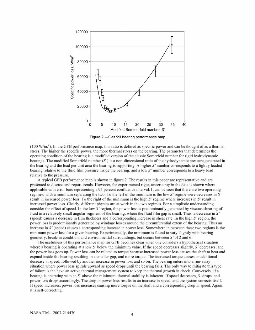
(100 W/in.2). In the GFB performance map, this ratio is defined as specific power and can be thought of as a thermal
stress. The higher the specific power, the more thermal stress on the bearing. The parameter that determines the
operating condition of the bearing is a modified version of the classic Somerfeld number for rigid hydrodynamic
bearings. The modified Somerfeld number (S’) is a non-dimensional ratio of the hydrodynamic pressure generated in
the bearing and the load per unit area the bearing is supporting. A higher S’ number corresponds to a lightly loaded
bearing relative to the fluid film pressure inside the bearing, and a low S’ number corresponds to a heavy load
relative to the pressure.
A typical GFB performance map is shown in figure 2. The results in this paper are representative and are
presented to discuss and report trends. However, for experimental rigor, uncertainty in the data is shown where
applicable with error bars representing a 95 percent confidence interval. It can be seen that there are two operating
regimes, with a minimum separating the two. To the left of the minimum is the low S’ regime were decreases in S’
result in increased power loss. To the right of the minimum is the high S’ regime where increases in S’ result in
increased power loss. Clearly, different physics are at work in the two regimes. For a simplistic understanding
consider the effect of speed. In the low S’ region, the power loss is predominantly generated by viscous shearing of
fluid in a relatively small angular segment of the bearing, where the fluid film gap is small. Thus, a decrease in S’
(speed) causes a decrease in film thickness and a corresponding increase in shear rate. In the high S’ region, the
power loss is predominantly generated by windage losses around the circumferential extent of the bearing. Thus an
increase in S’ (speed) causes a corresponding increase in power loss. Somewhere in between these two regions is the
minimum power loss for a given bearing. Experimentally, the minimum is found to vary slightly with bearing
geometry, break-in condition, and environmental surroundings, but occurs between S’ of 2 and 6.
The usefulness of this performance map for GFB becomes clear when one considers a hypothetical situation
where a bearing is operating at a low S’ below the minimum value. If the speed decreases slightly, S’ decreases, and
the power loss goes up. Power loss can be related to torque because increased power loss causes the shaft to heat and
expand inside the bearing resulting in a smaller gap, and more torque. The increased torque causes an additional
decrease in speed, followed by another increase in power loss and so on. The bearing enters into a run-away
situation where power loss spirals upward as speed drops until the bearing fails. The only way to mitigate this type
of failure is the have an active thermal management system to keep the thermal growth in check. Conversely, if a
bearing is operating with an S’ above the minimum, thermal stability is inherent. If speed decreases, S’ drops, and
power loss drops accordingly. The drop in power loss results in an increase in speed, and the system corrects itself.
If speed increases, power loss increases causing more torque on the shaft and a corresponding drop in speed. Again,
it is self-correcting.

NASA/TM—2007-214470 5
Based upon the above example, it is clear that desirable operation of GFB is in the high S’ region of the
performance map, above the minimum power loss value. The performance map, however, is not sufficient by itself,
it must be used in combination with other constraints and specifications to guide the design of GFB supported
turbomachinery. The rotor/bearing system previously proposed for the nuclear CBC turboaltornator (Prometheus
Project) serves as a good example to demonstrate the use of several tools for design guidance.
Figure 3 shows a model of the rotor from the Prometheus Project. The rotor has a centrifugal turbine and a
centrifugal compressor back-to-back on one end of the rotor. A permanent magnet alternator is mounted between
two journal GFBs, and a thrust bearing runner is mounted at the opposite end to the aero components for double-
acting thrust GFBs. For demonstration purposes, only the journal bearing closest to the aero components is
considered, but a similar approach would be used for the other journal bearing. Currently, there is no GFB
performance map for thrust bearings, however, Dykas, et al. (2006) conducted initial experimental investigations
that indicate thermal design features of thrust bearings can be more significant on thrust bearings than on journal
bearings. Four main criteria need to be met in the preliminary design stage: appropriate rotordynamic behavior,
sufficient structural strength, sufficient load capacity, and sufficient power loss margin, the later the topic of the
performance map.
In order to use the performance map to determine the margin of the Prometheus rotor bearing, several
parameters must be obtained. The viscosity of the fluid, Helium Xenon (He-Xe), must be known. According to El-
Genk (2006), a He-Xe mixture with a molecular weight of 40 g/Mol is likely to be used in systems such as this.
Johnson (2006) describes a technique to estimate the viscosity of He-Xe mixtures. A 40 g/Mol mixture at 500 K (the
expected temperature of the bearing cavity) will have a viscosity of 3.91 10–5
kg/ms. The viscosity of air at 500 K is
2.66 10–5
kg/ms. The steady state load on the bearing in question is 116 N (26 lb). The speed range for the
turboalternator is 20,000 to 45,000 rpm. The bearing L/D ratio is assumed to be 1 for the purpose of this calculation.
From DellaCorte, et al., (2006) it is desirable to have S’ between approximately 6 and 150. Therefore, it follows
from equation (1), with D = 2.71 105 N/m
3 krpm (1.0 lb/in.
3 krpm) (DellaCorte and Valco, 2001), that the diameter
and length of the bearing should be between 44.4 mm (1.75 in.) and 99.1 mm (3.90 in.). A bearing size anywhere
within this range should provide an acceptable level of specific power loss, and therefore be thermally stable.
S =0
D D( )Wt DL( )
(1)
Invoking the GFB load capacity rule-of-thumb (DellaCorte and Valco, 2001), a bearing at the small end of the
range (44.4 by 44.4 mm) would have a load capacity of 476 N (107 lb) at 20,000 rpm and 1070 N (241 lb) at
45,000 rpm. At the large end of the range (99.1 by 99.1 mm) the load capacity would be 11880 N (2670 lb) at
20,000 rpm and 26730 N (6010 lb) at 45,000 rpm. Thus, a bearing with a diameter and length in the above range
will easily have sufficient load capacity for the turboalternator application.

NASA/TM—2007-214470 6
It falls to the other two constraints, rotordynamic behavior and structural strength, to dictate the bearing size
within the above range for this application. The preliminary design calls for a bearing with a 68.6 mm (2.70 in.)
diameter and 50.8 mm (2.0 in.) length. This bearing does not have an L/D ratio of 1 as assumed earlier, but if one
recalculates S’, it ranges from 16 to 37, which is well within the desired range of 6 to 150. Howard and DellaCorte
(2006) present a rotordynamic analysis of the Prometheus rotor system, and concludes that the rotor/bearing system
should have acceptable rotordynamic behavior with the assumed bearing size. The authors are not aware of a stress
analysis of this rotor, but from experience the size seems reasonable for a machine of this class and speed range. At
any rate, the method outlined demonstrates how one would approach a preliminary analysis for integration of GFB
into a new application using the GFB performance map and load capacity rule-of-thumb for initial bearing sizing. It
should be noted that the performance map and rule-of-thumb were developed using data obtained in air at standard
pressure, and are subject to further refinement as more data is collected. The following section describes a recent
extension of the performance map data to higher pressure.
Power Loss At High Pressure
The only published data on high pressure GFB performance (Dobler and Miller, 1978) shows an alarming
increase in power loss with both increasing pressure and gas molecular weight. A preliminary experimental
investigation has been conducted to identify GFB power loss in current bearing designs at high ambient pressures.
The current investigation utilized a Gen III (DellaCorte and Valco, 2001) corrugated bump foil design GFB
(Heshmat, 2000). Tests were conducted in air at pressures up to 120 psia in the High Pressure Rig (HPR).
The HPR consists of an electric drive motor with a maximum speed of 24,000 rpm with a modified output shaft.
The output shaft accepts custom made foil bearing journals that have been prepared with the NASA PS304 solid
lubricant coating. Radial load is applied to the bearing by the use a series of deadweight donut made of Aluminum,
Stainless Steel, and a high density tungsten alloy (Anvilloy) having weights of 6.05, 14.1, and 35.0 N (1.36, 3.16,
and 7.87 lb), respectively. Bearing reaction torque (friction) is measured with a commercially available precision
load cell mounted 66 mm (2.6 in.) from the center of the bearing.
The various pressure power loss results are plotted on the GFB performance map shown in figure 4. The
vertical axis shows the power loss divided by the bearing projected area (L/D). The horizontal axis shows the
modified Somerfeld number, S’ defined above. In addition to the data obtained in this investigation, figure 4 also
contains the data from Dobler and Miller plotted on the performance map.
The preliminary data obtained in this investigation indicates that the power loss minimum for a GFB is not
greatly affected by air pressures up to 0.82 MPa (120 psia). However in the high S’ operating regime further concern
over bearing power loss may be warranted. It is important to note that on the results presented in figure 4 a constant
D-coefficient was assumed for the bearing performance at all pressures. However it is a well understood qualitative
fact that load capacity for foil bearings increases with ambient pressure. The precise quantitative nature of this effect
is not known at this time for the particular bearings tested in this experimental program.

NASA/TM—2007-214470 7
Rotor/Stator Windage Losses at High Ambient Pressure
An additional concern with high pressure systems is loss due to windage in the rotor/stator gap of the alternator.
Losses due to windage on the alternator components are not well understood as a function of high operating
pressure. A body of work does exist in the open literature for low pressure applications. This work is largely
applicable to space-based flywheel energy storage devices. Extrapolation of this low pressure data from the sub-
atmospheric range to the tens of atmosphere range is the only method currently available to predict the performance
of such machines. In order to reduce the uncertainty in the current state of the art as well as more fully understand
the flow physics within the rotor/stator gap, an experimental program has been conducted. These experiments
utilized the pressure vessel and drive motor of the High Pressure Journal Bearing Rig with additional hardware
designed to simulate the stator. The stator fixture was supported on precision bearings to facilitate the measurement
of windage torque and power loss.
Analytic Approach
The most appropriate analytic approach for modeling the flow physics, and hence calculating the torque and
power loss, is to treat the system as flow between two concentric cylinders with the outer cylinder at rest and the
inner cylinder rotating. Such an analysis is illustrated in Schlichting (1987) with complementary experimental
measurements from G.I. Taylor. Results of such an analysis are often plotted in non-dimensional parameters of
Moment Coefficient versus Taylor Number. The fluid flow enters three distinct regions in such an analysis. First, for
Taylor numbers less than 41, the flow is laminar and torque is independent of density (or pressure) for a given
temperature. The second region from Taylor number of 41 to 400 is characterized by the presence of Taylor
vortices. In this region the torque increases compared to the laminar region, but still follows the trend of being
largely independent of pressure. In the third region for Taylor number greater than 400 the flow becomes turbulent.
In this region the torque then increases with increasing pressure. Theoretically the torque increase should follow the
pressure increase to the 0.8 power.
In addition to the basic Taylor-Couette flow physics that contribute to the alternator windage losses, factors
such as grooved stator walls, axial flow, and heat transfer to the fluid will contribute to the losses. The most
significant of these factors is the grooved wall stator. If one draws comparisons between the Taylor-Couettte chart
and the Moody chart for pipe flow, wall roughness (or grooved stators) would have the effect of increasing the
torque at a given Taylor number. This increase can be quite substantial and depends strongly on the depth and pitch
of the grooves. In general axial flow and heat transfer tend to destabilize the fluid flow and initiate turbulence at
lower Taylor numbers; however their precise effects can be significant or subtle and would need to be evaluated for
a specific design.
Experimental Approach
The experimental approach taken in this characterization study was to simulate a smooth walled stator over a
smooth walled journal. The journal had a length of 76.2 mm (3.0 in.), an outer diameter of 35.3 mm (1.390 in.) and
was tested to 12,000 rpm. The tests were limited to this speed due to the increased overhung length and mass on the
High Pressure Rig drive motor. Modifications to the rig are now underway to increase the speed range to 42,000
rpm. Although the speed was limited, due to the fact that testing occurred beyond 3.1 MPa (450 psia), Taylor
numbers in excess of 4,000 were tested. The gap was chosen both to simulate current alternator design practice and
to have similarity to the data of G.I. Taylor. The gap tested was 0.457 mm (0.018 in.) which yields a gap to radius
ratio of 0.026. The notion behind these initial tests is to experimentally set the “lower bound” of windage losses.
Parametric experiments are anticipated in the future to characterize the effect of grooved stators, axial flow, and heat
transfer. The experiments were conducted in a similar way in which the high pressure bearing power loss
experiments were conducted. The only difference between the two experiments was that the bearing was self-
supporting while the stator of the windage experiment was supported by a bearing cartridge to maintain rotational
freedom of the static stator can. Reaction torque was measured with a commercially available high accuracy load
cell mounted 3.2 mm (0.125 in.) from the axis of rotation.
Dimensional experimental results are shown in figure 5. These results were obtained in a carbon dioxide
environment at pressure from 0.1 to 3.1 MPa. In this figure specific power loss is plotted as a function of pressure
for speeds of 5,000 and 10,000 rpm. The data indicates that for low rpm a nearly constant power loss exists. At
higher speeds the trend becomes linear with some indication of curvature.

NASA/TM—2007-214470 8
Nondimensional experimental results are shown in figure 6. These results are remarkably similar to the trends
shown by Schlichting and Taylor. In the current experiments there is an indication that the turbulent transition can
be delayed until a Taylor number of 1,000.
Also shown in figure 6 are commercial alternator manufacturer predictions (from Hamilton Standard – HS, and
Honeywell/Calnetix – HW/Cal) for windage losses. These predictions strongly indicate that there exists a roughness
factor which each manufacturer employs and is specific to their individual design practice.
Rotor/Stator windage has been experimentally evaluated for representative alternator designs up to 2.8 MPa
(400 psia). Based upon this initial effort, it appears that the windage power loss level will be of the same order of
magnitude, probably slightly less, than expected foil gas bearing power losses. Smooth walled stators with gap to
rotor radius ratios of 0.026 have been evaluated to provide guidance to system pressure trade studies. Experimental
evaluations are recommended to continue to evaluate higher speeds, gap to radius ratios, stator groove pitch and
depth, axial flow, and heat transfer in order to capture the complete design space of potential Closed Brayton Cycle
power conversion system alternators.
Start-Up Torque Requirements
There is a strong desire to understand the start-up torque requirements of a CBC rotor system using GFBs
because it dictates how much on-board energy storage is needed. The torque required to rotate a GFB supported
rotor is greatest when the rotor is in contact with the stator before there is sufficient speed to generate a fluid film
separating the two surfaces. To initiate rotation sufficient torque must be applied to the rotor to overcome the sliding
frictional forces in the journal bearings, thrust bearings, rotor inertia and the required rotational acceleration. The
following describes an effort to predict the start-up torque for the nuclear CBC rotor of the Prometheus Program.
The sliding frictional forces in journal bearings are a function of the bearing (spring) preload and the
gravitational load the bearing is supporting. The bearing resistive torque due to gravitational load can be calculated
by knowing the static coefficient of friction (COF) between the bearing and shaft. To acquire this value a test was
performed on a rotor from NASA Glenn’s high speed thrust bearing test rig (Bauman, 2005). The test rig is an Oil-
Free design that consists of a 36.6 mm (1.44 in.) diameter rotor supported on two journal foil bearings and is shown

NASA/TM—2007-214470 9
in figure 7. The rotor is representative of the machines in the size class of the CBC and will provide torque values
that are scalable for future designs.
As shown in figure 7 there are two journal bearings supporting the rotor. Each bearing’s top foil is coated with
Korolon (Mohawk Innovative Technology, Inc.), a high temperature solid lubricant which is representative of the
advanced foil bearing coatings that are commercially available (Hestmat, et al., 2005). The mating shaft surfaces are
coated with a thin layer of electrolyzed Nickel. Setup for testing consisted of installing the bearings in their correct
locations on the rotor, supporting the bearings on blocks and then attaching a short beam to one end of the rotor.
Calibrated weights were then added to the end of the beam to impart a torque on the rotor until rotational motion
occurred. The coefficient of friction and the preload are assumed to be the same for both bearings. Summing torques
gives:
TB1 +TB2 + 2TP Ta = 0 (2)
TB1 and TB2 are calculated by the product of friction coefficient, , the load supported by the bearing, N, and the
shaft radius, r:
μr NB1 + NB2( ) + 2TP =Ta (3)
The applied torque, Ta, was found to be approximately 0.141 N-m (1.25 in.-lb). The sum of NB1 and NB2 is the
weight of the rotor which was measured to be 31.0 N (6.98 lb). The torque due to the bearing preload was measured
in a previous experiment to be 0.0467 N-m (0.413 in.-lb). Solving for in equation (3) results in a value for the
COF of about 0.1. This is typical of solid lubricant coatings for foil air bearings.
The contribution of the thrust bearing to the start-up friction was obtained by using NASA’s foil thrust bearing
test rig to measure torque on a single-acting foil thrust bearing during start-up and shut-down cycles. An axial load
of 6.89 kPa (1.0 psi) was used to simulate the expected preload in the CBC machine. The bearing pads are coated
with Korolon™ and the mating thrust runner was coated with NASA PS304, another high temperature solid
lubricant coating (DellaCorte, 1998). Data collected from the start-stop tests indicate that the thrust bearing will
contribute approximately 0.339 N-m (3.0 in.-lb) of resistive torque to the system. Since the CBC utilizes a double-
acting thrust bearing, the resistive torque due to preload will be 0.678 N-m (6.0 in.-lb).
The proposed design of the CBC rotor has the turbine and compressor back-to-back in an overhung
configuration. A model of the rotor is shown above in figure 3.
The total length of the rotor is 0.445 m (17.5 in.) and the shaft OD is 68.6 mm (2.70 in.). Computer modeling of
the rotor estimates its weight to be approximately 93.4 N (21.0 lb) with a polar moment of inertia of 0.0125 Nm-s2
(0.111 lbf-in.-s2). The foil bearings at station 2 and 6 were calculated to be supporting 21.8 N (4.89 lb) (acting up)
and 115 N (25.9 lb) (acting down), respectively. The start-up torque can now be calculated from:
Tstart T2 T6 2TP 2TThrust = I (4)
The rotational acceleration should be as rapid as possible to minimize sliding at the journal bearing-shaft
surface that can cause wear. Previous tests on foil bearings operating on a 34.9 mm (1.38 in.) diameter journal
indicate lift-off occurs around 2000 rpm. The diameter of the JIMO rotor is almost twice this diameter suggesting
that lift-off will occur at a lower speed, but to be conservative, 2000 rpm will be used. It is also assumed that the

NASA/TM—2007-214470 10
requirement for lift-off is two seconds once start-up begins. Therefore, the necessary rotational acceleration is
104.7 rad/s2. Substituting values and solving equation (4) for Tstart yields:
Tstart = 2.55Nm 22.62 in. lb( ) (5)
Once sliding begins the torque requirement to sustain rotation drops since the kinematic COF is typically less
than static COF. Upon development of the gas film and rotor lift-off the torque requirement for rotation will further
decline. To help with understanding the power requirements to drive the rotor during full speed operation NASA is
currently conducting in-house tests to characterize power loss as a function of speed, bearing geometry and load.
The data shown for this hypothetical rotor serves as a guide and offers typical values for foil bearing preload
and static friction coefficients encountered in foil bearings. To accurately model future CBC turbine rotor systems a
detailed analysis accounting for specific geometry effects would be required.
Misalignment
A concern for all turbomachinery, and therefore applicable to CBC space power systems is the degree of
misalignment that a rotor bearing system can tolerate. The limits on misalignment dictate how precisely housings
must be manufactured and how much thermal distortion can be tolerated. GFBs have been touted as having the
ability to handle high degrees of misalignment relative to other bearing types, thus making them easier to integrate
into high speed, high temperature applications. Very little work has been reported on GFB misalignment. Carpino
(1994) analyzed misalignment effects and found that load capacity is not affected strongly, but minimum film
thickness decreases with increased misalignment. However, those results were for very small angular misalignments
(maximum angle equal to C/L radians) relative to those in the present tests (maximum angle of 10.4 C/L radians).
Since the bearings presently used in the class of machines for which GFBs are considered as replacements are
typically angular contact ball bearings, it is appropriate to compare the misalignment tolerance of the two. The
amount of misalignment ball bearings can tolerate depends on the size, load, speed, and required life, but according
to Zaretsky (1994), a typical allowable misalignment limit for angular contact ball bearings is 0.0003 radians. A test
program was instigated to quantify the level of misalignment GFB can tolerate for comparison and to help guide
future oil-free turbomachinery design programs including space power systems.
The rotordynamic simulator test rig at NASA Glenn Research Center (fig. 8) was used to conduct misalignment
tests on two 50.8 mm (2.00 in.) diameter journal GFBs. The rotordynamic simulator rig is an air turbine driven test

NASA/TM—2007-214470 11
rig that features completely oil-free operation. There are two journal GFBs near opposite ends of the rotor with two
disks (a turbine and thrust bearing runner) mounted between the two journal bearings. In the configuration shown,
the rotor weighs approximately 31 N (7.0 lb) and is roughly symmetric such that each journal bearing supports half
the rotor weight. The journal bearings are housed in independent structures that can be moved relative to each other
in transverse and angular directions. The test rig is described in more detail in (Howard, 2006). The independent
bearing supports allows the operator to impose a known misalignment on the two journal bearings using a laser
based alignment system that attaches to each bearing structure.
For the initial series of tests described here, one bearing structure was held fixed while the other was sequentially
moved a small amount laterally (0.127 mm for each test) imposing a misalignment to both bearings until a failure was
observed. Two physical quantities were measured during the tests, temperature and coast down time. The temperature
was measured using thermocouples mounted to the underside of the bearing top foil close to the edge, 90° from top
dead center in both directions, and at both ends for a total of 8 thermocouples, 4 on each bearing (fig. 9). Each test
was run until the temperatures stopped increasing, indicating steady state operation. Data was collected for
20,000 rpm and 30,000 rpm. The expected result was to see overall higher temperatures and higher temperature
gradients between opposite sides of the bearings (T2 vs. T1 for example) at higher misalignment levels. The other
observed quantity, coast down time was used as a qualitative measure of bearing torque. It was anticipated that as
the level of misalignment increased, the coast down time would decrease due to higher bearing losses.
Figure 10 shows the temperature data for steady operation at 20,000 rpm. In general, there is an upward trend
on temperature with higher misalignment, as anticipated. The 30,000 rpm data, omitted here for brevity, shows the
same trends with higher overall temperatures. The exceptions to the trend are T3 and T4. One possible cause of the
downward trend in T3 and T4 is their proximity to the turbine, seen in figure 9. Since T3 and T4 are adjacent to the
turbine, they are affected by the temperature of the turbine outlet flow. The turbine is driven by compressed air, and
as it expands through the nozzle, it gets cold. At higher misalignment, more flow is required to counteract the higher
torque, resulting in more turbine exhaust. The increased turbine exhaust may cool the bearing in the location where
T3 and T4 are mounted.

NASA/TM—2007-214470 12
When the GFBs are misaligned, the bearings become more and more edge-loaded. The thermocouples were
placed on the bearing in such a way to try to see the effect of the edge-loading in the form of increased temperature.
For example, as the right hand bearing in figure 9 is moved upward in the picture, the film thickness near
thermocouples T2, T4, T6, and T8 decreases, while at T1, T3, T5, and T7 it increases. Because thinner film are
associated with higher heat generation, T2 should be hotter than T1, T4 hotter than T3, T6 hotter than T5, and T8
hotter than T7. In general, this result is observed. It should be noted that thermocouple T6 was damaged during the
tests after the 20,000 rpm run at 0.89 mm (0.035 in.) of misalignment, so there is no data for T6 beyond that test. Up
to that point, it was behaving as expected.
Figure 11 shows the coast down time data as a function of misalignment. This data was not collected for the
aligned case and the smallest misalignment case, but the trend shows that there is a general decrease in the time it
takes to coast to a stop from 25,000 rpm as the misalignment increases. The decrease in coast down time can be
attributed to increased power loss, or torque in the bearings. Modifications are planned for the rig to enable direct
torque measurements in the future.
At a maximum misalignment of 1.4 mm (0.055 in.) and 20,000 rpm, a failure was experienced and testing was
stopped. GFBs can fail in several ways (Dykas and Howard, 2004; Radil, Howard, and Dykas, 2002), but this failure
was a typical failure that is seen when load capacity is reached. The torque in the bearings increases rapidly,
accompanied by an increase in temperature with no increase in speed or load. At the onset of the failure, it was
observed that more turbine pressure was needed to maintain the same speed. As the failure progressed, more turbine
pressure could not overcome the increase in torque, and speed decreased even with more pressure. When this
occurred, the test was stopped.
It was determined that for the configuration of the rotordynamic simulator test rig, 1.4 mm (0.055 in.) is the
limit of misalignment that the GFBs can sustain. From the failure mode, it is reasonable to assume that the load
capacity of the bearings decreased with increased misalignment until the load capacity fell below the weight of the
rotor, and failure was observed. It appears then, that the amount of misalignment a GFB can tolerate is likely a
function of how much load it is supporting in relation to its load capacity.
In the case studied here, the maximum misalignment angle, given a separation distance of 240 mm (9.5 in.), is
0.0058 radians. Compared to angular contact ball bearings, this limit is nearly 20 times the amount of misalignment
tolerable. The advantage over radial ball bearings and cylindrical roller bearings is less at 2 and 6 times respectively,
but still significant.
Conclusions
Power conversion systems based upon a CBC turboalternator are under consideration for space power
generation applications. Gas foil bearings are a candidate for rotor support in such systems for their high speed
capability as well as their ability to use the process fluid as a lubricating fluid. Successful integration of GFBs into
space power CBC systems requires advancing the state-of-the-art in foil bearing knowledge.
To address that need, the current work presents a power loss model used in combination with a load capacity
rule-of-thumb to determine an appropriate range of bearing sizes for a rotor representative of a Closed Brayton
Cycle Turbo-Alternator. Journal GFBs between 44.4 and 99.1 mm in diameter will provide the necessary load

NASA/TM—2007-214470 13
capacity while generating a manageable amount of power loss for thermal stability. In addition, the effects of
elevated pressures on both power loss and windage loss were presented. It was found that the minimum power loss
of a given GFB does not change significantly with pressure, but at high modified Sommerfeld numbers, high
pressure could become a concern. The preliminary windage loss results indicate that for low speed, windage loss is
not a strong function of pressure, but as speed increases, the pressure effect becomes more pronounced. Future
testing to higher speed and pressure is planned to elaborate on this result. Start-up torque requirements of a GFB
supported turbo-alternator is a critical design parameter, yet was previously unknown. An experiment was
conducted to determine the start-up torque requirements of a rotor representative of a CBC turbo-alternator, and
found that the start motor for such a machine would need to supply 2.55 Nm of torque for starting. The amount of
misalignment allowable in the rotor/bearing system of a CBC turbo-alternator is also an important design
consideration as it affects the precision with which the structure must be manufactured, and the amount of thermal
distortion that can be tolerated. Experiments presented herein determined that journal GFBs within the appropriate
size range for a CBC rotor system can tolerate up to 0.006 radians of angular misalignment, twenty times the
acceptable amount for angular contact ball bearings. The results presented here are expected to help guide future
work and preliminary integration efforts of GFBs into CBC turbomachinery.
References
Bauman, S., An Oil-Free Thrust Foil Bearing Facility Design, Calibration and Operation, NASA/TM—2005-213568, NASA
Glenn Research Center, Cleveland, OH, 2005.
Carpino, M., Peng, J.P., and Medvetz, L., “Misalignment in a Complete Shell Gas Foil Journal Bearing,” Tribology Transactions
37, 829–835 (1994).
DellaCorte, C., The Evaluation of a Modified Chrome Oxide Based High Temperature Solid Lubricant Coating for Foil Gas
Bearings, NASA TM-1998-208660, NASA Glenn Research Center, Cleveland, OH, 1998.
DellaCorte, C., and Pinkus, O., Tribological Limitations in Gas Turbine Engines a Workshop to Identify the Challenges and Set
Future Directions, NASA/TM 2000-210058-REV1, NASA Glenn Research Center, Cleveland, OH, 2000.
DellaCorte, C., and Valco, M.J., ”Load Capacity Estimation of Foil Air Journal Bearings for Oil-Free Turbomachinery
Applications,” STLE Tribology Transactions 43, 795–801 (2001).
DellaCorte, C., Radil, K.C., Bruckner, R.J., and Howard, S.A., A Preliminary Foil Gas Bearing Performance Map, NASA/TM—
2006-214343, NASA Glenn Research Center, Cleveland, OH, 2006.
Dobler, F.X., Miller, L.G., Mini-BRU/Bips Foil Bearing Development, NASA CR-159442, NASA Lewis Research Center,
Cleveland, OH, 1978.
Dykas, B.D., and Howard, S.A., “Journal Design Considerations for Turbomachine Shafts Supported on Foil Air Bearings,”
Tribology Transactions 47, 508–516 (2004).
Dykas, B.D., DellaCorte, C., Prahl, J.M., and Bruckner, R.J., “Thermal Management Phenomena in Foil Gas Thrust Bearings,” in
Proceedings of Turbo Expo 2006: Power for Land, Sea, and Air (IGTI), ASME, Barcelona, Spain, 2006, Paper no. 2006–91268.
El-Genk, M.S., and Tournier, J.M., “Selection of Noble Gas Binary Mixtures for Brayton Space Nuclear Power Systems,” in
Proceedings of 4th International Energy Conversion Engineering Conference and Exhibit (IECEC), AIAA, Reston, VA,
2006, Paper no. AIAA–2006–4168.
Elliot, J.O., Reh, K., and MacPherson, “Lunar Fission Surface Power System Design and Implementation Concept,” in the
Proceedings of the Space Technology and Applications International Forum, edited by M.S. El-Genk, AIP Conf. Proc. 813,
Melville, New York, 2006, pp. 942–952.
Heshmat, H., “Advancements in the Performance of Aerodynamic Foil Journal Bearings: High Speed and Load Capability,”
Transactions of the ASME J. of Tribology 116, 287–295 (1994).
Heshmat, H., “High load capacity compliant foil hydrodynamic journal bearing,” U.S. Patent 6,158,893, 2000.
Howard, S.A., and DellaCorte, C., Gas Foil Bearings for Space Propulsion Nuclear Electric Power Generation, NASA/TM
2006-214115, NASA Glenn Research Center, Cleveland, OH, 2006.
Howard, S.A., A New High Speed Oil-Free Turbine Engine Rotordynamic Simulator Test Rig, NASA/TM 2006-214489, NASA
Glenn Research Center, Cleveland, OH, 2006.
Johnson, P., A Method for Calculating Viscosity and Thermal Conductivity of a Helium-Xenon Gas Mixture, NASA/CR 2006-
214394, NASA Glenn Research Center, Cleveland, OH, 2006.
Lavelle, T.M., Khandelwal, S.C., and Owen, A.K., Intermediate Fidelity Closed Brayton Cycle Power Conversion Model,
NASA/TM—2006-213993, NASA Glenn Research Center, Cleveland, OH, 2006.
Mason, L.S., “A Power Conversion Concept for the Jupiter Icy Moons Orbiter, ” AIAA Journal of Propulsion and Power 20,
902–910, (2003).
Radil, K.C., Howard, S.A., and Dykas, B.D., The Role of Radial Clearance on the Performance of Foil Air Bearings,
NASA/TM—2002-211705, NASA Glenn Research Center, Cleveland, OH, 2002.
Schlichting, H., Boundary-Layer Theory, Seventh Edition, McGraw-Hill, New York, NY, 1987, pp. 525–532.

This publication is available from the NASA Center for AeroSpace Information, 301–621–0390.
REPORT DOCUMENTATION PAGE
2. REPORT DATE
19. SECURITY CLASSIFICATION OF ABSTRACT
18. SECURITY CLASSIFICATION OF THIS PAGE
Public reporting burden for this collection of information is estimated to average 1 hour per response, including the time for reviewing instructions, searching existing data sources,gathering and maintaining the data needed, and completing and reviewing the collection of information. Send comments regarding this burden estimate or any other aspect of thiscollection of information, including suggestions for reducing this burden, to Washington Headquarters Services, Directorate for Information Operations and Reports, 1215 JeffersonDavis Highway, Suite 1204, Arlington, VA 22202-4302, and to the Office of Management and Budget, Paperwork Reduction Project (0704-0188), Washington, DC 20503.
NSN 7540-01-280-5500 Standard Form 298 (Rev. 2-89)Prescribed by ANSI Std. Z39-18298-102
Form ApprovedOMB No. 0704-0188
12b. DISTRIBUTION CODE
8. PERFORMING ORGANIZATION REPORT NUMBER
5. FUNDING NUMBERS
3. REPORT TYPE AND DATES COVERED
4. TITLE AND SUBTITLE
6. AUTHOR(S)
7. PERFORMING ORGANIZATION NAME(S) AND ADDRESS(ES)
11. SUPPLEMENTARY NOTES
12a. DISTRIBUTION/AVAILABILITY STATEMENT
13. ABSTRACT (Maximum 200 words)
14. SUBJECT TERMS
17. SECURITY CLASSIFICATION OF REPORT
16. PRICE CODE
15. NUMBER OF PAGES
20. LIMITATION OF ABSTRACT
Unclassified Unclassified
Technical Memorandum
Unclassified
1. AGENCY USE ONLY (Leave blank)
10. SPONSORING/MONITORING AGENCY REPORT NUMBER
9. SPONSORING/MONITORING AGENCY NAME(S) AND ADDRESS(ES)
National Aeronautics and Space AdministrationWashington, DC 20546–0001andU.S. Army Research LaboratoryAdelphi, Maryland 20783–1145
National Aeronautics and Space AdministrationJohn H. Glenn Research Center at Lewis FieldCleveland, Ohio 44135–3191
Available electronically at http://gltrs.grc.nasa.gov
January 2007
NASA TM—2007-214470ARL–TR–4036
E–15762
19
Gas Foil Bearing Technology Advancements for Closed Brayton Cycle Turbines
Samuel A. Howard, Robert J. Bruckner, Christopher DellaCorte,and Kevin C. Radil
Space bases; Turbogenerators; Electric propulsion; Bearings; Foil bearings; Gas bearings
Unclassified -UnlimitedSubject Categories: 14, 20, and 37
WBS 997180.10.03.01
Closed Brayton Cycle (CBC) turbine systems are under consideration for future space electric power generation. CBCturbines convert thermal energy from a nuclear reactor, or other heat source, to electrical power using a closed-loop cycle.The operating fluid in the closed-loop is commonly a high pressure inert gas mixture that cannot tolerate contamination.One source of potential contamination in a system such as this is the lubricant used in the turbomachine bearings. GasFoil Bearings (GFB) represent a bearing technology that eliminates the possibility of contamination by using the workingfluid as the lubricant. Thus, foil bearings are well suited to application in space power CBC turbine systems. NASA GlennResearch Center is actively researching GFB technology for use in these CBC power turbines. A power loss model hasbeen developed, and the effects of a very high ambient pressure, start-up torque, and misalignment, have been observedand are reported here.
Prepared for Space Technology and Applications International Forum (STAIF–2007) sponsored by the Institute for Spaceand Nuclear Power Studies at the University of New Mexico, Albuquerque, New Mexico, February 11–15, 2007. SamuelA. Howard, Robert J. Bruckner, and Christopher DellaCorte, NASA Glenn Research Center; Kevin C. Radil, U.S. ArmyResearch Laboratory, NASA Glenn Research Center. Responsible person, Samuel A. Howard, organization code RXT0,216–433–6076.

