research article the failure criterion of single-layer...
TRANSCRIPT

Research ArticleThe Failure Criterion of Single-Layer Spherical LatticeShell Based on Kinetic Energy
Panfeng Ba, Yigang Zhang, Jinzhi Wu, and Zhihao Zhang
Spatial Structures Research Center, Beijing University of Technology, Beijing 100124, China
Correspondence should be addressed to Panfeng Ba; [email protected]
Received 25 April 2015; Accepted 7 July 2015
Academic Editor: Dapeng P. Du
Copyright © 2015 Panfeng Ba et al. This is an open access article distributed under the Creative Commons Attribution License,which permits unrestricted use, distribution, and reproduction in any medium, provided the original work is properly cited.
The dynamic failure criterion of single-layer spherical lattice shells has been an important research subject. The paper examinesdynamic failures of single-layer spherical lattice shells and proposes the structure dynamic failure criterion based on the kineticenergy. The failure criterion was demonstrated through the dynamic failure test on a single-layer spherical lattice shell. Then,simulation analysis was carried out through two cases with material damage taken into account. The proposed failure criterioncan accurately identify failure moments caused either by strength fracture or by stability fracture.
1. Introduction
Single-layer spherical lattice shell is highly favored in practicefor its light weight and graceful appearance by experts andscholars. The recent high frequency of earthquakes has chal-lenged the extensive application of this light-weighted shell.Thus, the dynamic failure of the single-layer spherical latticeshell has been considered as an important research subject.The intensity fracture and stability fracture were extensivelyidentified by experts as the major dynamic failures of single-layer spherical lattice shell. Shen et al. [1–3] identified thatdynamic strength failure occurs when the ratio of plasticbar is greater than 42% and maximum node displacementexceeds span 1/100 in theK8 single-layer spherical lattice shellfrom an overall perspective of integral structure. Du et al.[4] established a double-control principle based on plasticitydissipated energy and the ultimate displacement, whichconsiders the failure of integral structure caused by damageaccumulation and thus could identify the strength fractureand stability fracture. Nevertheless, Du’s principle could notgo further than providing evaluation of degree of damage.Zhang and Peil [5] defined the stability concept and proposeda method identifying the stability of integral structure bychanges in stability, considering the total potential energy ofthe rod and the ratio between increment in structural strain
energy and potential energy. Nevertheless, Zhang’s method islimited to the elasticity problem.
In theory, failure mechanism of single-layer sphericallattice shell and determining the structure of the ultimateload are important subject with maximum displacement andthe degree of plastic as a major focus. Despite being highlyvalued in engineering application, the effective preestimatingmethod of the failure of single-layer for the spherical latticeshell which could be applied to improve structure failure-resisting capacity by strengthening vulnerable spots is yetto be further explored. The authors resort to detecting amacroscopic quantity as a preestimating failure criterionwhich is easy to calculate and also reflects the characteristicsof the overall structural failure. The authors note that theremust be vibration and dramatic changes in kinetic energyin dynamic failures. According to the findings stated above,the paper endeavors to propose the dynamic failure criterionbased on the kinetic energy and explores whether there existsa failure criterion coefficient applicable to identify dynamicfailure and failuremoment under strong shock.Moreover, thepaper also sets out to verify the validity of the proposed failurecriterion coefficient by referring to the collapse test data andthe case which stimulates the process of the collapse of single-layer spherical lattice shells.
Hindawi Publishing CorporationMathematical Problems in EngineeringVolume 2015, Article ID 485710, 7 pageshttp://dx.doi.org/10.1155/2015/485710

2 Mathematical Problems in Engineering
2. The Dynamic Failure Criterion ofSingle-Layer Spherical Lattice Shells
In finite element calculation, the kinetic energy equation canbe written as follows:
𝐸𝑘 (𝑡) =1
2{�̇� (𝑡)}
𝑇
[𝑀] {�̇� (𝑡)} , (1)
where 𝐸𝑘(𝑡) is kinetic energy of whole structure, [𝑀] is themassmatrix of structure, {𝑈(𝑡)} is the displacement ofmatrix,and {�̇�(𝑡)} is the first derivative. During any arbitrary periods[𝑡, 𝑡+Δ𝑡], the increment in the kinetic energy can be expressedas follows:
Δ𝐸𝑘 = 𝐸𝑘 (𝑡 + Δ𝑡) − 𝐸𝑘 (𝑡)
=1
2{�̇� (𝑡 + Δ𝑡)}
𝑇
[𝑀] {�̇� (𝑡 + Δ𝑡)}
−1
2{�̇� (𝑡)}
𝑇
[𝑀] {�̇� (𝑡)} .
(2)
Δ𝐸𝑘 is the increment of kinetic energy.The acceleration at anyperiod can be expressed as �̈�(𝛽) as follows:
{�̇� (𝑡 + Δ𝑡)} = {�̇� (𝑡)} + �̈� (𝛽) Δ𝑡. (3)
{�̈�(𝛽)} is the second derivative. Substituting (3) into (2), wecan get the following:
Δ𝐸𝑘
=1
2{{�̇� (𝑡)} + �̈� (𝛽) Δ𝑡}
𝑇
[𝑀] {{�̇� (𝑡)} + �̈� (𝛽) Δ𝑡}
−1
2{�̇� (𝑡)}
𝑇
[𝑀] {�̇� (𝑡)}
=1
2{�̇� (𝑡)}
𝑇
[𝑀] {�̇� (𝑡)}
+1
2{{�̇� (𝑡)}
𝑇
[𝑀] {�̈� (𝛽)}} Δ𝑡
+1
2{�̈� (𝛽)}
𝑇
[𝑀] {�̇� (𝑡)} Δ𝑡
+1
2{�̈� (𝛽)}
𝑇
[𝑀] {�̈� (𝛽)} Δ𝑡2
−1
2{�̇� (𝑡)}
𝑇
[𝑀] {�̇� (𝑡)} .
(4)
The single-layer spherical reticulated shell is a symmetricstructure. The mass matrix of single-layer spherical latticeshell is symmetric matrices. An equation could be obtained:[𝑀] = [𝑀]
𝑇, where 𝑝 is a constant in this equation. Then,anther equation can be written as follows:
{�̇� (𝑡)}𝑇
[𝑀] {�̈� (𝛽)} = 𝑝 = 𝑝𝑇
= [{�̇� (𝑡)}𝑇
[𝑀] {�̈� (𝛽)}]
𝑇
= {�̈� (𝛽)} [𝑀] {�̇� (𝑡)}𝑇
.
(5)
Stage A1
Stage A2
Stage D
Stage E
Stage C2
Stage C1
Stage B
Expression 𝜙 = 0
𝜙 < 0
𝜙 < 0
𝜙 > 0
𝜙 > 0
𝜙 > 0
𝜙 > 0 𝜙 > 0
U(t)
Δt
Figure 1: The relationship between displacement and coefficient.
Substituting (5) into (4), we can get
Δ𝐸𝑘 = {�̈� (𝛽)}𝑇
[𝑀] {�̇� (𝑡)} Δ𝑡
+1
2{�̈� (𝛽)}
𝑇
[𝑀] {�̈� (𝛽)} Δ𝑡2.
(6)
Because Δ𝑡 > 0, when both sides of (6) divided by the timevariable of Δ𝑡, we can get constant 𝜙:
𝜙 =Δ𝐸𝑘
Δ𝑡
= {�̈� (𝛽)}𝑇
[𝑀] {�̇� (𝑡)}
+1
2{�̈� (𝛽)}
𝑇
[𝑀] {�̈� (𝛽)} Δ𝑡.
(7)
To be clear in discussion, several sign conventions couldbe stipulated as follows. The upward movement deviatingfrom balance shaft is considered as positive and downwardmovement away from balance shaft as negative. Signs ofnode displacement, velocity, and acceleration velocity are inaccordance with the above sign convention. The structurevibrates along the balance shaft. Vibration of situations couldbe vividly demonstrated in trajectory function 𝑈(𝑡) as stagesof A, B, C, D, and E in Figure 1.
At Stage A1, the structure vibrates downward the balanceshaft and the trajectory function𝑈(𝑡) demonstrates that mostparticles moved downward away from the balance shaft. Thespeed is larger; the restoring force causes acceleration fromzero to positive. So �̇�(𝑡) < 0, �̈�(𝛽) > 0, and the coefficient 𝜙is greater than zero at the multiple consecutive time Δ𝑡.
When the movement was between Stages A1 and A2 and|�̇�(𝑡)| = (1/2)|�̈�(𝛽)|Δ𝑡, the coefficient 𝜙 = 0, which indicateskinetic energy increment, was zero.
When the movement reaches Stage A2 and �̇�(𝑡) < 0,�̈�(𝛽) > 0, the trajectory function 𝑈(𝑡) demonstrates thatmost of the particles moved downwards deviating from

Mathematical Problems in Engineering 3
the balance shaft. Nevertheless, |�̇�(𝑡)| < (1/2)|�̈�(𝛽)|Δ𝑡 wasstill applicable in this stage and the coefficient𝜙 is greater thanzero at the multiple consecutive time Δ𝑡.
At Stage B and when �̇�(𝑡) > 0, �̈�(𝛽) > 0, trajectoryfunction 𝑈(𝑡) expresses most of the particles deviated fromthe balance shaft upward. The acceleration direction is inaccordance with the previous stage, while the velocity direc-tion changed. In other words, 𝜙 was greater than zero at themultiple consecutive time Δ𝑡.
By such analogy, the changing rule of coefficient 𝜙 inStages C and D can be expressed as shown in Figure 1.
At Stage E, the global vibration of the structure beginscontinuous downward accelerated movement from zero.During the process, the accelerated speed direction changed,�̇�(𝑡) < 0, and �̈�(𝛽) < 0. Moreover, signs of the accelerationand velocity are in accordance with each other at this stage.
The above discussion expresses that the coefficient 𝜙contained themovement characteristics of structure. Relativeto the static equilibrium state, the particle trajectory canbe reflected according to the velocity and acceleration ofsymbols. The symbols of speed and acceleration determinedthe symbols of coefficient 𝜙 at the same time.
It can be noted in Figure 1 from phases D to E that, duringmultiple continuous Δ𝑡, 𝜙 > 0, which will cause continuousincrease in speed. It can be also noticed that as both the valueof 𝜙 and the kinetic energy of the structure escalate sharply,the corresponding structural displacement will continuouslyincrease.Thus, it is fairly reasonable to identify the structuralfailure when the excessive structural displacement eventuallycauses the structural kinetic failure.Therefore, the previouslylast corresponding moment when 𝜙 = 0 can be recognized asthe structural failure moment, which indicates the structureentered the failure state.
From what stated above, conclusions could be made thatwhen the coefficient 𝜙 remains positive duringminor contin-uous multiple time increments and the recordedmaximum 𝜙value (𝜙𝑡=𝑎) is much larger than all the previously recorded𝜙 values, the structural failure occurred. Correspondingly,during continuous increase of the 𝜙 value till 𝜙𝑡=𝑎, the failuremoment occurred when the 𝜙 value approaches zero fromnegative.Therefore, the coefficient 𝜙 could be considered as afailure criterion coefficient.
3. Table Test Verification
3.1. Introduction to Table Test. Combined with the shelltests conducted by scholars at home and abroad [6–10], theshaking table experiment adopts the single-layer sphericallattice shell model. The span is 3m and there are 4 loops.The rise-span ratio is 1 : 5 and the stress bars are the steelpipes whose diameters are Ø10 × 1mm or Ø8 × 1mm asshown in Figure 2. Solid spheres are installed on sphericaljoints, with each sphere having a diameter of 200mm andweighing 32.4 kg, as shown in Figure 3. Considering the self-vibration characteristics of test model, we used the verticalharmonic load to enhance vibration. Harmonic load is thebasic component of dynamic load and all kinds of compli-cated earthquake loads can be divided into combinations
600
3000
3000
𝜙8
𝜙10
Figure 2: The size of test model.
Figure 3: The real test model.
of harmonic load with different frequencies and amplitudes.Consequently, harmonic load is adopted in the test.
The test was conducted in the Structural Testing Centerof Beijing University of Technology. In the test, we used twosets of noncontact displacement acquisition test which areproduced by the company of IMETRUM in England. Thetest applied a tracking shot to record the displacement of allnodes. The process of collapse under the strong earthquakewas shown in Figure 4.
3.2. Test Result Analysis. Particles’ absolute displacementtime history was calculated, with particles’ displacement timehistory curve and the displacement input of bearings takeninto consideration. Furthermore, the particle movementvelocity history was obtained based on the derivation ofdiscrete points and all particles’ kinetic energy history. Then,the failure criterion coefficient 𝜙 of each moment (Δ𝑡 =11ms) was calculated.The above procedures were conductedto make the program easier. It is observed that when𝑇 = 63.543 s, the coefficient 𝜙 is less than zero. However,the failure criterion coefficient values are all greater thanzero at three consecutive moments (63.554 s, 63.566 s, and63.577 s), which are, respectively, 7.004 × 10⁵, 1.437 × 10⁶, and
4 Mathematical Problems in Engineering
(a) 𝑇 = 51.0 s
Sag
(b) 𝑇 = 63.5 s
(c) 𝑇 = 63.8 s (d) 𝑇 = 64.3 s
(e) 𝑇 = 65.1 s
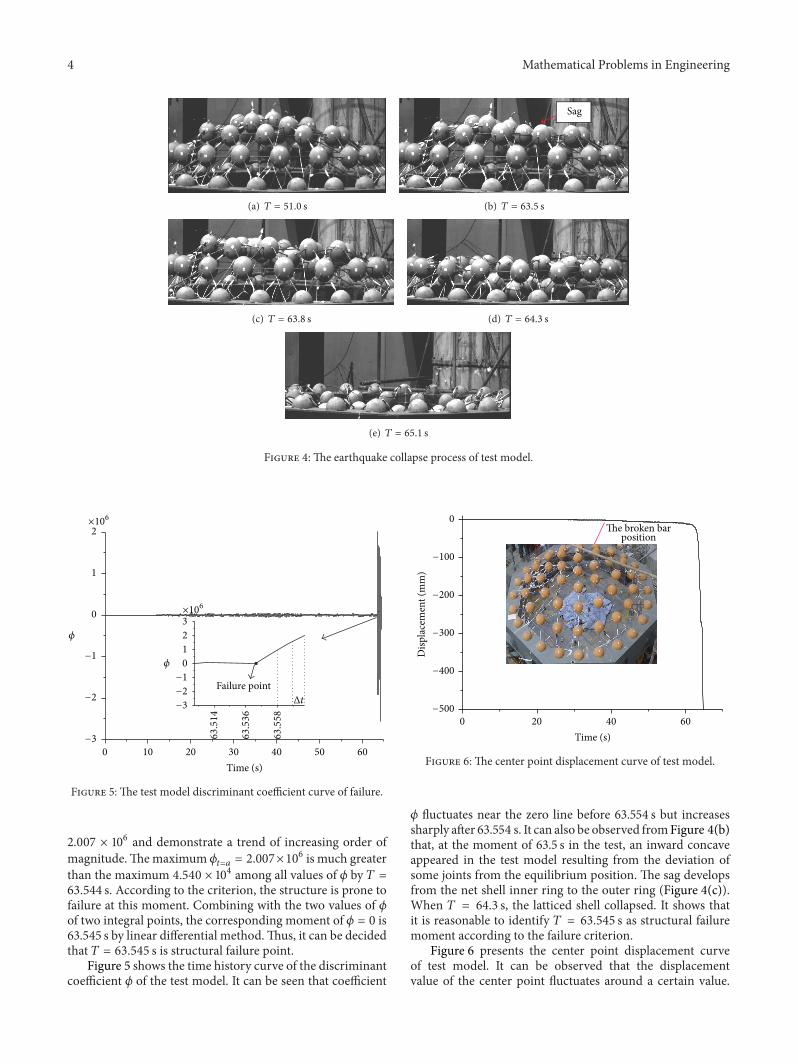
Figure 4: The earthquake collapse process of test model.
2
1
0
−1
−2
−3
×106
×106
𝜙 2
3
1
0
−1
−2
−3
𝜙
0 10 20 30 40 50 60
Time (s)
Δt
Failure point
63.514
63.536
63.558
Figure 5: The test model discriminant coefficient curve of failure.
2.007 × 10⁶ and demonstrate a trend of increasing order ofmagnitude.Themaximum 𝜙𝑡=𝑎 = 2.007×10
6 is much greaterthan the maximum 4.540 × 10⁴ among all values of 𝜙 by 𝑇 =63.544 s. According to the criterion, the structure is prone tofailure at this moment. Combining with the two values of 𝜙of two integral points, the corresponding moment of 𝜙 = 0 is63.545 s by linear differential method.Thus, it can be decidedthat 𝑇 = 63.545 s is structural failure point.
Figure 5 shows the time history curve of the discriminantcoefficient 𝜙 of the test model. It can be seen that coefficient
−100
−200
−300
−400
−500
0The broken bar
Time (s)0 20 40 60
Disp
lace
men
t (m
m)
position
Figure 6: The center point displacement curve of test model.
𝜙 fluctuates near the zero line before 63.554 s but increasessharply after 63.554 s. It can also be observed fromFigure 4(b)that, at the moment of 63.5 s in the test, an inward concaveappeared in the test model resulting from the deviation ofsome joints from the equilibrium position. The sag developsfrom the net shell inner ring to the outer ring (Figure 4(c)).When 𝑇 = 64.3 s, the latticed shell collapsed. It shows thatit is reasonable to identify 𝑇 = 63.545 s as structural failuremoment according to the failure criterion.
Figure 6 presents the center point displacement curveof test model. It can be observed that the displacementvalue of the center point fluctuates around a certain value.

Mathematical Problems in Engineering 5
13333
40000
Figure 7: The shell model of paper [1].
At about 40 s, there has been significant bar fracture whenthe center point displacement time history curve decreasedslightly. Though the center point displacement is 3.6mm, thestructure can still bear load and has not yet entered the failurestate. At about 63 s, the center point displacement sharplyincreased, prone to failure. It is a further test for verifying thecriterion based on the kinetic energy which can accuratelydetermine the exact time of structure failure.
4. The First Calculation Model
4.1. Model Data. The span of single-layer spherical latticeshell is 40m in paper [1]. Rise-span ratio is 1/3. All bar is hot-rolled steel pipe of which the ribbed bar section is Ø114×3.0,Ø127×3.5, and Ø140×4.5 (mm).The bearing hinge pedestalis assumed, roofing gravity load of 200 kg/m2. The roofinggravity load will be concentrated onto the nodes. Rayleighdamping is used, with its damping factor as 0.02. Finiteelement method first establishes unit stiffness matrices bydividing the bar into several units and then thewhole stiffnessmatrix. The paper uses finite element software ABAQUS.The model of Figure 7 introduced UMAT subroutine that,considering material damage [10], the amplitude of theharmonic load is 100 gal. The load frequency is 2.6Hz.
Literature [1] concludes that when the load amplitude is97 gal, there is neither significant local rigidity nor obviousdisplacement in vibration equilibrium position. Only 0.06%of the whole structure become plastic bars and little verticaldisplacement took place. When the load amplitude is 97 gal,the local destruction becomes obvious and rapidly developstill the collapse of the whole structure, which could beregarded as a typical example of stability failure. Literature[1] also presents the history curve of the whole structuredisplacement under different loads in Figure 8. According toFigure 8, the structure failure moment starts at about 5∼6 s.
4.2. Analysis of Calculation Results. The history curve offailure coefficient 𝜙 of the structure model was calculatedunder 100Gal seismic amplitude. When 𝑇 = 2.305 s, therecorded value of coefficient 𝜙 is 1.08 × 10⁷. The failurecoefficient 𝜙was, respectively, 1.1 × 10⁹ and −4.48 × 10⁸ at two
Disp
lace
men
t (m
)
0.4
0.2
0.0
0 2 4 6 8 10 12 14
Time (s)
97gal100 gal
Figure 8: The displacement history curve of shell model.
4.00E + 010
2.00E + 010
0.00E + 000
−2.00E + 010
−4.00E + 010
𝜙
0 2 4 6 8
Time (s)
Failure point
Figure 9: The history curve of failure coefficient.
other subsequent moments. These values, however, had yetnot met the failure criterion and thus could be ignored.
Fluctuation developed according to the recorded historycurve of coefficient 𝜙. At the time of 𝑇 = 4.67 s, the recordedvaluewas 9.3× 10⁷.Then, the value of the coefficient remainedpositive and increased rapidly during 154 consecutive Δ𝑡 ≈30ms. For the three different time points (4.72 s, 5.45 s, and7.06 s), the 𝜙 values were, respectively, 2.32 × 10⁷, 1.82 × 10⁹,and 2.6 × 10¹⁰, showing a sharply increasing trend. Accordingto the failure criterion, 4.634 s was defined as the failurepoint of the overall structure through calculation by thelinear difference method. As it can be seen from Figure 9, thestructural failure moment has obvious characteristic whichmeets the failure criterion.
The failure moment 4.634 s is slightly ahead of the failuremoment identified in literature [1].This ismainly because thispaper considered the material damage accumulation effect inthe calculation. It also shows that the application coefficient𝜙 can accurately distinguish the failure time of the structurein the dynamic stability failure.

6 Mathematical Problems in Engineering
1
2
3
4
y
x z
8000
40000
Figure 10: The diagram of overall structure.
5. The Second Calculation Model
5.1. Model Data. Figure 10 [11] demonstrates that a six-ringSchwedler single-layer spherical lattice shell across 40 metersspan was established, with vector ratio of 1/5, roof gravityload of 2.5 kN/m2, and all ground holds hinged.The softwareof 3D3S is used for reasonable design and calculation. Allbars are hot-rolled steel pipe, of which the main ribbed barsection is Ø165 × 5 and the rest of the link rod and diagonalsection are Ø140 × 4. All bars are divided into four units ofequal length and each unit’s cross section is divided into 8fibers of equal length. Considering geometric nonlinearity,the material yield point is 235MPa and the initial elasticmodulus is 2.06 × 10⁵MPa with Poisson’s ratio as 0.3.
The UMAT subroutine is introduced into the modelstructure shown in Figure 10 to analyze seismic response,taking damage accumulation into account. Three-directionalNorthridge wave is input, of which the PGA of 𝑋-directionis 1300Gal and the seismic peak values of 𝑌-direction and𝑍-direction are, respectively, 0.85 and 0.65 times of𝑋’s.
5.2. Result Analysis. The calculation result shows that when𝑇 = 3.68 s, the structure’s coefficient 𝜙 is 1.67 × 10⁹, which iscomparatively large.When𝑇 = 3.64 s and 3.75 s, two differenttiming points before and after 3.68 s, the correspondingfailure coefficient 𝜙 is, respectively, 1.07 × 10⁸ and −1.82 × 10⁹.According to the structure failure criterion, this fluctuationof coefficient 𝜙 does not result in the structure failure. Thefact that only a few bars become plastic bars together withthe partial sag caused the fluctuation of the failure coefficient𝜙. Later, during a succession of over 60 Δ𝑡 ≈ 15ms, the 𝜙values remain positive values and keeps an increasing trend.When 𝑇 = 24.64 s, 25.24 s, and 25.77 s, the corresponding𝜙 values are, respectively, 1.4 × 10⁸, 4.18 × 10⁹, and 1.19 ×10¹⁰. And eventually the obtained maximum coefficient is1.51 × 1010, which is much greater than the maximum valuerecorded before𝑇 = 24.64 s. Considering the structure failurecriterion and the method of linear difference, when 𝑇 =24.61 s, the failure coefficient is zero. Figure 11 demonstratesthe oscillation curve of the failure criterion coefficient, fromwhich the failure moment could be clearly observed.
3.00E + 010
2.00E + 010
1.00E + 010
0.00E + 000
−2.00E + 010
−1.00E + 010
−3.00E + 010
𝜙
0 5 10 15 20 25
Time (s)
Failure point
Figure 11: The history curve of coefficient (PGA = 1300Gal).
0
1
2
3
4
5 10 15 20 25
Time (s)
2
0
−2
−4
−6
−8
−10
×103
Disp
lace
men
t (m
m)
Figure 12: The displacement history curve of different point.
Figure 12 shows the time history curves of different nodedisplacement. It can be observed in Figure 12 that momentswhen different joint displacement increases sharply are dis-crete. It is probably inadequate to identify the failure momentsimply based on the displacement of the structure jointsand might further require researchers’ judgment. Especiallywhen there is partial sag, this inadequatemethodmight resultin the misjudgment and mistakes. Contrastingly, the failurecriterion used in this paper could be considered as adequateand reasonable.
The above analysis demonstrates that the vibration of thesecond calculation model becomes failure when 𝑇 = 24.61 s.Considering the mentioned criterion of failure moment,results show that 61.7% of bars in the structure have becomeplastic bars. Obviously, the damaged structure could serveas a typical example of dynamic strength fracture. Thus, aconclusion could be drawn that the failure criterion proposedin this paper can accurately identify the failuremoment of thesingle-layer spherical lattice shells under dynamic strengthfracture.

Mathematical Problems in Engineering 7
6. Conclusion
In this study, the failure identification equation of single-layerspherical lattice shells is deduced based on kinetic energy.Thedynamic failure criterion is verified by shaking table test dataand two cases. Thus, several conclusions could be drawn asfollows:
(1) The structure failure moment under dynamic loadingcan be identified based on the shift of failure criterioncoefficient 𝜙 between positive or negative and itsmagnitude.
(2) The dynamic failure criterion based on kinetic energyis simple, practical, and thus easy to be programmed.
(3) The proposed failure criterion can accurately identifyfailure moment of single-layer spherical lattice shellsdamaged either by strength fracture or by stabilityfracture.
Conflict of Interests
The authors declare that there is no conflict of interestsregarding the publication of this paper.
Acknowledgments
This work is partially supported by Natural Science Foun-dation of China under Grant nos. 51178009 and 91315301and Beijing Lab of Earthquake Engineering and StructuralRetrofit.
References
[1] S.-Z. Shen and X.-D. Zhi, “Failure mechanism of reticular shellssubjected to dynamic actions,” China Civil Engineering Journal,vol. 38, no. 1, pp. 11–20, 2005.
[2] F. Fan, X.-D. Zhi, and S.-Z. Shen, Failure Mechanism of Retic-ulated Shells Under Earthquake, Science Press, Beijing, China,2014.
[3] G.-B. Nie, Research on Spatial Hysteretic Experiment and Con-stitutive Equation for Element of Reticulated Shells, HarbinInstitute of Technology, 2008.
[4] W.-F. Du, B.-Q. Gao, and S.-L. Dong, “Double-control criterionof dynamical strength failure for single layer latticed shells,”Journal of ZhejiangUniversity, vol. 41, no. 11, pp. 1916–1926, 2007.
[5] Q.-L. Zhang and U. Peil, “Stability analysis of elastics structuresunder arbitrary excitation,”China Civil Engineering Journal, vol.31, no. 1, pp. 26–32, 1998.
[6] Y. Hiyama, H. Takashima, T. lijima, and S. Kato, “Bucklingbehavior of aluminum ball jointed single layered reticulardomes,” International Journal of Space Structures, vol. 15, no. 2,pp. 81–94, 2000.
[7] Z.-X. Li, Z.-Y. Shen, C.-G.Deng et al., “Research on the dynamicstability of steel reticulated shells via shaking table test,” Journalof Experimental Mechanics, vol. 14, no. 4, pp. 484–491, 1999.
[8] J. Ye andR. Pan, “Shaking table test on collapse process of single-layer spherical shells,” Journal of Building Structures, vol. 34, no.4, pp. 81–90, 2013.
[9] G. Nie, F. Fan, X. Zhi, and J. Dai, “Shaking table test onfailuremechanismof single-layer reticulated dome,”ChinaCivilEngineering Journal, vol. 46, no. 10, pp. 17–25, 2013.
[10] G.-B. Nie, F. Fan, X.-D. Zhi, and J.-W. Dai, “Dynamic character-istics test of a single-layer reticulated dome model,” Journal ofVibration and Shock, vol. 32, no. 22, pp. 200–204, 2013.
[11] Y.-G. Zhang, P.-F. Ba, J.-Z. Wu, and W.-J. Zhang, “Damageevolution and bearing capacity analysis of single layer sphericalshell based on aging,” Journal of Tianjin University (Science andTechnology), vol. 47, supplement 7, pp. 74–78, 2014.

Submit your manuscripts athttp://www.hindawi.com
Hindawi Publishing Corporationhttp://www.hindawi.com Volume 2014
MathematicsJournal of
Hindawi Publishing Corporationhttp://www.hindawi.com Volume 2014
Mathematical Problems in Engineering
Hindawi Publishing Corporationhttp://www.hindawi.com
Differential EquationsInternational Journal of
Volume 2014
Applied MathematicsJournal of
Hindawi Publishing Corporationhttp://www.hindawi.com Volume 2014
Probability and StatisticsHindawi Publishing Corporationhttp://www.hindawi.com Volume 2014
Journal of
Hindawi Publishing Corporationhttp://www.hindawi.com Volume 2014
Mathematical PhysicsAdvances in
Complex AnalysisJournal of
Hindawi Publishing Corporationhttp://www.hindawi.com Volume 2014
OptimizationJournal of
Hindawi Publishing Corporationhttp://www.hindawi.com Volume 2014
CombinatoricsHindawi Publishing Corporationhttp://www.hindawi.com Volume 2014
International Journal of
Hindawi Publishing Corporationhttp://www.hindawi.com Volume 2014
Operations ResearchAdvances in
Journal of
Hindawi Publishing Corporationhttp://www.hindawi.com Volume 2014
Function Spaces
Abstract and Applied AnalysisHindawi Publishing Corporationhttp://www.hindawi.com Volume 2014
International Journal of Mathematics and Mathematical Sciences
Hindawi Publishing Corporationhttp://www.hindawi.com Volume 2014
The Scientific World JournalHindawi Publishing Corporation http://www.hindawi.com Volume 2014
Hindawi Publishing Corporationhttp://www.hindawi.com Volume 2014
Algebra
Discrete Dynamics in Nature and Society
Hindawi Publishing Corporationhttp://www.hindawi.com Volume 2014
Hindawi Publishing Corporationhttp://www.hindawi.com Volume 2014
Decision SciencesAdvances in
Discrete MathematicsJournal of
Hindawi Publishing Corporationhttp://www.hindawi.com
Volume 2014 Hindawi Publishing Corporationhttp://www.hindawi.com Volume 2014
Stochastic AnalysisInternational Journal of