research article photocatalytic oxidation of...
TRANSCRIPT

Research ArticlePhotocatalytic Oxidation of Trichloroethylene in Water Usinga Porous Ball of Nano-ZnO and Nanoclay Composite
Sol-A Bak,1 Myong-Shin Song,1 In-Tak Nam,2 and Woong-Geol Lee3
1Research Center of Advanced Convergence Processing on Materials, Kangwon National University,Samcheok 245711, Republic of Korea2Department of Nano Applied Engineering, Kangwon National University, Chuncheon 200701, Republic of Korea3SPM Co., Ltd., Kangwon 220841, Republic of Korea
Correspondence should be addressed to Myong-Shin Song; [email protected] and In-Tak Nam; [email protected]
Received 1 May 2015; Accepted 30 August 2015
Academic Editor: Xiao-Miao Feng
Copyright © 2015 Sol-A Bak et al.This is an open access article distributed under theCreativeCommonsAttributionLicense,whichpermits unrestricted use, distribution, and reproduction in any medium, provided the original work is properly cited.
The presence of nondegradable organic compounds and xenobiotic chemicals in water is a great concern for the general publicbecause of their polar properties and toxicity. For instance, trichloroethylene (TCE) is a widely used solvent in the chemicalindustry, and it is also a contaminant of soil, surface water, and groundwater. Recent studies on new treatment technologies haveshown that photocatalyst-based advanced oxidation processes are appropriate for removing these polar and toxic compounds fromwater. The objective of this study was to remove TCE from water using novel nano-ZnO-laponite porous balls prepared fromphotocatalyst ZnO with nanoscale laponite. These nano-ZnO-laponite porous balls have a porosity of approximately 20%. A lowerinitial concentration of TCE resulted in high removal efficiency. Moreover, the removal efficiency increased with increasing pHin the photocatalytic degradation experiments employing UVC light with nano-ZnO-laponite. The optimal dosage of nano-ZnO-laponite was 30 g and the use of UVC light resulted in a higher removal efficiency than that achieved with UVA light. In addition,the removal efficiency of TCE significantly increased with increasing light intensity. We think that TCE’s removal in water by usingporous ball of nano-ZnO and nanoclay composite is a result of degradation from hydroxide by photons of nano-ZnO and physicalabsorption in nanoclay.
1. Introduction
Rapid urbanization and industrialization have resulted inlarge-scale emission of organic compounds that do not occurnaturally, which has led to serious environmental pollu-tion. Many organic compounds are synthesized by ongoingdevelopments and applications of the chemical industry, anda majority of the synthetic organic compounds are non-degradable, which means that they can be degraded neithernaturally nor by biological treatment, including activatedsludge. Many of these nondegradable organic compoundsremain in nature for long periods, not only damaging theecosystem but also threatening public health when they comeinto human contact.Thus, there is an urgent need to eliminatesuch compounds. In particular, these substances are knownas the leading factors of soil and underground-water con-tamination. The reality is that nondegradable organic com-pounds cannot be easily treated in existing sewage-disposal
plants. Water-quality regulations for sewage-disposal andwastewater-disposal plants, like biochemical oxygen demand(BOD), chemical oxygen demand (COD), and limits forsuspended solids (SS), are becoming more stringent, andit has been more difficult to meet the allowable emissionstandards by only treating degradable substances [1–5].
Analysis results for underground water, sampled from25,000–140,000 sites annually in South Korea, indicate thatthe percentage of ground water polluted by trichloroethylene(TCE), which exceeds the maximum defined in the qualitystandard for underground water, has increased: 15% in 2004,16% in 2005, and 29% in 2006 [6–8]. A report from the Min-istry of Environment (Korea) that provides measurementsof underground water contamination indicates that, of theharmful substances exceeding the standards, the proportionof TCEwas the highest and its contamination figures have notimproved over the last four years. Moreover, the amount of
Hindawi Publishing CorporationJournal of NanomaterialsVolume 2015, Article ID 160212, 8 pageshttp://dx.doi.org/10.1155/2015/160212

2 Journal of Nanomaterials
Table 1: Physical and chemical properties of ZnO.
Purity Mean diameter (nm) Specific surface (m2⋅g−1) Dry loss (%) Combustion loss (%) Pb (%) Cu (%)99.7% 30 >90 <0.3 <0.2 ≤0.037 ≤0.0002
detected TCEwas high in industrial complex areas and urbanresidential areas, demonstrating an urgent need for treatmentof TCE-contaminated ground water [9, 10].
In this study, as an alternative to using TiO2for eliminat-
ing nondegradable organic compounds, the most commonlyused photocatalyst, laponite, which has good photoperme-ability, wasmixedwith ZnO,which is known to be excellent atdegradingTCE.Thenano-ZnO-laponite complexwas shapedinto balls to increase the interface with TCE, and its TCEremoval efficiency was then evaluated.
2. Experimental
2.1. Materials
2.1.1. ZnO-Laponite Composite. ZnO has attracted consider-able interest because it has a wide band gap (3.37 eV) at roomtemperature and its electrical properties are improved byadding impurities and exposing thematerial to UV, or addinga luminous element in blue, since its exciton band energyis 60meV. The nano-ZnO powder used in the experimentswas purchased from SH Energy & Chemical, Korea, andthe average particle diameter was 30 nm. Table 1 lists thegeneral properties of ZnO.We used Laponite RD (RockwoodAdditives Ltd., UK) as the photocatalyst. It is an inorganicprotective powder with a disilicate structure (Figure 1) [11–14]. The general physical properties of laponite are listed inTable 2.
2.1.2. TCE. The TCE used in this study was a liquid productwith a purity of 99.5% or higher, manufactured by Sigma-Aldrich inUSA. It is a very volatile substancewith amolecularweight of 131.39 g and a specific gravity of 1.465 g⋅cm−3. Forour experiments, we prepared TCE with a concentration of10 ppm.
2.1.3. NaOH and HCl. We used NaOH as an alkaline solventand HCl as an acidic solvent to control the pH of TCE. TheNaOH was 99.5% pure and a first-class reagent; the HCI wassupplied by Tsurumi Soda (Japan).
2.2. Methods
2.2.1. Formation of Ball-Shaped Nano-ZnO-Laponite Compos-ite. We formed the ZnO-laponite composite, the photocata-lyst used in this study, into ball-shaped particles. The averagesize of each ball was about 3mm. We prepared laponite bymixing it with water in a 1 : 10 (w/w) ratio with an agitator for5min, followed by drying at room temperature, resulting in agel-state product. Another round of agitation was performedafter mixing the gel laponite with nano-ZnO powder andadding a small amount of thickener. The mixing ratios of
Table 2: Physical and chemical properties of laponite.
(a)
Physical propertyPowder color WhiteDensity (kg⋅m−3) 1000Surface area (m2⋅g−1) 370pH (2wt% suspension) 9.8
(b)
Chemical composition (dry basis) (%)SiO2
59.9MgO 27.5Li2O 0.8
Na2O 2.8
LOI∗ 8.2∗LOI = limiting oxygen index.
Table 3: Mixing proportions of nano-ZnO-laponite balls.
Type Nano-ZnO (wt%) Laponite (wt%) Water (wt%)1 90 10 102 88 12 103 86 14 10
the gel laponite and nano-ZnO are listed in Table 3. Weformed themixed samples into ball shapes using a pill maker.The resulting nano-ZnO-laponite balls were dried in air for48 h.
2.2.2. Instrumentation. We used UVA and UVC lamps(Philips, Netherlands) in the experiments.Thewavelengths ofthe UVA and UVC lamps were 360 and 254 nm, respectively.The respective specifications for the lamps are given inTable 4.
The reactor used in this study was custom-made. Anillustration of the setup is shown in Figure 2, and the actualsetting is shown in Figure 3. We inserted a quartz tube at thecenter and installed a UV lamp at each vertex of the reactor;the quartz tube was completely filled with the nano-ZnO-laponite composite. The walls of the reactor were acrylic. Inaddition, the exterior surface of the reactor was designed toprohibit the passage of light, while the interior surface had amirrored coating.This setup offered the advantage of reusingthe light source since the light could perform photocatalyticscanning after being reflected (without exiting the reactor).
2.2.3. Methods. The quartz tube was completely filled withthe nano-ZnO-laponite composite (30 g), the photocatalystused in the study. Then, the previously prepared TCE(60mL), with a concentration of 10mg⋅L−1, was added to

Journal of Nanomaterials 3
𝜕+
Single laponite crystal
0.92nm
25nm𝜕+
𝜕+
𝜕+
𝜕+
𝜕+
(a)
Tetrahedral
NaOSi
OHMg, Li
Octahedral
Tetrahedral
Interlayer region
Trioctahedral smectite
(b)
Single laponite crystal
Separationinto primaryparticle
Hydration of sodium ions
0.92nm
25nm
H2O H2O𝜕+
𝜕+
𝜕+
𝜕+
𝜕+
𝜕+
𝜕+𝜕+𝜕+
𝜕+𝜕+𝜕+
𝜕+
𝜕+
𝜕+
𝜕+
𝜕+
𝜕+
Na+ Na+
Na+ Na+
Na+ Na+ Na+ Na+ Na+(aq) (aq)
Swelling ofstructure
𝜕+ 𝜕
+ 𝜕+𝜕+𝜕+
(c)
Figure 1: General properties of laponite: (a) single laponite crystal; (b) chemical structure of laponite; and (c) addition of laponite to water.
Table 4: Operating conditions for UVA and UVC.
Type Power (W) Dimensions (mm) Lamp current (A) Ultraviolet output (W)Length, 𝐿 Diameter, 𝐷
TL8W/05 (UVA) 8 288.3 16 0.15 1.0TUV 8W (UVC) 7 237.0 16 0.15 2.1
the quartz tube.The quartz tube was affixed inside the reactorwith both ends sealed. The UV lamps were then turned on,and samples were collected at 30-minute intervals for 2 h.To induce instant deposition of the photocatalytic powderin the collected samples, we used a centrifugal separator. Wechecked the TCE removal efficiency by setting the changes ininitial concentration, pH changes, lamp type, and the numberof lamps (intensity of light) as variable factors.
2.2.4. Analysis. The analysis was using a purge-and-trap gaschromatograph (GC; 6890N, Agilent, USA) and mass spec-trometer (MS) (purge-trap GC-MS) system. The operatingconditions are as follows: the carrier gas, N
2gas, entered
at 1–5mL⋅min−1; the column temperature was 35–220∘C, setat a heating/cooling rate of 10∘C⋅min−1; and the detectortemperature was 230∘C. We used a VOCOL (Sigma-Aldrich)capillary tube column.Theactivation conditions for the purge
4 Journal of Nanomaterials
Quartz pipeZnO-laponite
UV lamp
Figure 2: Scheme of the reactor.
Figure 3: Experimental setup of the reactor.
and trap devices are as follows: purge temperature = 30∘C;purge time = 11min; trap-bake temperature = 220∘C; andtrap-bake time = 7min.
2.2.5. Measurement Methods of Removal Efficiency. Removalefficiency was measured as a percentage of removed concen-tration of TCE by injected initial concentration of TCE.
3. Results and Discussion
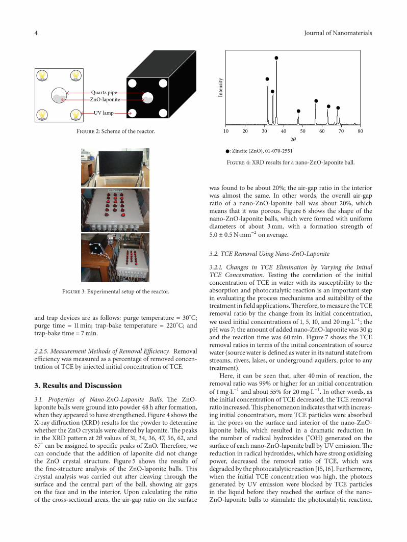
3.1. Properties of Nano-ZnO-Laponite Balls. The ZnO-laponite balls were ground into powder 48 h after formation,when they appeared to have strengthened. Figure 4 shows theX-ray diffraction (XRD) results for the powder to determinewhether the ZnO crystals were altered by laponite.The peaksin the XRD pattern at 2𝜃 values of 31, 34, 36, 47, 56, 62, and67∘ can be assigned to specific peaks of ZnO. Therefore, wecan conclude that the addition of laponite did not changethe ZnO crystal structure. Figure 5 shows the results ofthe fine-structure analysis of the ZnO-laponite balls. Thiscrystal analysis was carried out after cleaving through thesurface and the central part of the ball, showing air gapson the face and in the interior. Upon calculating the ratioof the cross-sectional areas, the air-gap ratio on the surface
Inte
nsity
20 30 40 50 60 70 80102𝜃
: Zincite (ZnO), 01-070-2551
Figure 4: XRD results for a nano-ZnO-laponite ball.
was found to be about 20%; the air-gap ratio in the interiorwas almost the same. In other words, the overall air-gapratio of a nano-ZnO-laponite ball was about 20%, whichmeans that it was porous. Figure 6 shows the shape of thenano-ZnO-laponite balls, which were formed with uniformdiameters of about 3mm, with a formation strength of5.0 ± 0.5N⋅mm−2 on average.
3.2. TCE Removal Using Nano-ZnO-Laponite
3.2.1. Changes in TCE Elimination by Varying the InitialTCE Concentration. Testing the correlation of the initialconcentration of TCE in water with its susceptibility to theabsorption and photocatalytic reaction is an important stepin evaluating the process mechanisms and suitability of thetreatment in field applications.Therefore, tomeasure the TCEremoval ratio by the change from its initial concentration,we used initial concentrations of 1, 5, 10, and 20mg⋅L−1; thepH was 7; the amount of added nano-ZnO-laponite was 30 g;and the reaction time was 60min. Figure 7 shows the TCEremoval ratios in terms of the initial concentration of sourcewater (sourcewater is defined aswater in its natural state fromstreams, rivers, lakes, or underground aquifers, prior to anytreatment).
Here, it can be seen that, after 40min of reaction, theremoval ratio was 99% or higher for an initial concentrationof 1mg⋅L−1 and about 55% for 20mg⋅L−1. In other words, asthe initial concentration of TCE decreased, the TCE removalratio increased.This phenomenon indicates thatwith increas-ing initial concentration, more TCE particles were absorbedin the pores on the surface and interior of the nano-ZnO-laponite balls, which resulted in a dramatic reduction inthe number of radical hydroxides (∙OH) generated on thesurface of each nano-ZnO-laponite ball by UV emission.Thereduction in radical hydroxides, which have strong oxidizingpower, decreased the removal ratio of TCE, which wasdegraded by the photocatalytic reaction [15, 16]. Furthermore,when the initial TCE concentration was high, the photonsgenerated by UV emission were blocked by TCE particlesin the liquid before they reached the surface of the nano-ZnO-laponite balls to stimulate the photocatalytic reaction.
Journal of Nanomaterials 5
(a) (b)
Figure 5: SEM images of a nano-ZnO-laponite ball: (a) surface phase; (b) interior phase.
Figure 6: Shape of nano-ZnO-laponite balls.
Therefore, the amount of photons absorbed on the surface ofthe nano-ZnO-laponite balls decreased, which also reducedthe TCE removal ratio [17, 18]. Moreover, Carp et al., Yang etal., and Li et al. [17–19] reported that the reaction byproducts(intermediates) generated during the photocatalytic reactionalso affect the TCE degradation rate; that is, source water witha high initial TCE concentration generates a large amount ofreaction byproducts, resulting in an overall decrease in theTCE removal ratio.
3.2.2. TCE Removal Characteristics with respect to the Amountof Inserted Nano-ZnO-Laponite. We also examined how theamount of inserted nano-ZnO-laponite balls affected theabsorption and photocatalytic reaction of TCE (Figure 8).The amounts of inserted nano-ZnO-laponite were 10, 20,30, and 40 g. As this amount was gradually increased, therespective removal efficiencies were found to be 55.8, 71.5,88.6, and 89.9%, indicating that the TCE removal ratioalso increased continuously. This result was primarily dueto the increase in the total surface area of nano-ZnO-laponite. A secondary factor for this behavior was that, as
0
10
20
30
40
50
60
70
80
90
100
0 10 20 30 40 50 60Irradiation time (min)
20mg/L10mg/L
5mg/L1mg/L
Rem
oval
effici
ency
(%)
Figure 7: Effect of initial concentration of TCE on photocatalyticdegradation (initial concentration of TCE = 1–20mg⋅L−1; nano-ZnO-laponite loading = 30 g; pH = 7.0; irradiation time = 60min;and UVC intensity = 8.4mW⋅cm−2).
the active sites available for absorption and photocatalyticreaction were increased, large amounts of radical hydroxideand superoxide could be generated [17]. However, we onlyobserved slight increases in the TCE removal ratio whenthe amount of inserted nano-ZnO-laponite was above 30 g.Thus, an unlimited increase of nano-ZnO-laponite balls didnot continue to enhance the photocatalytic degradation. Inotherwords, the economic reality and the effects of secondaryenvironmental byproducts (byproducts generated after use)should be considered. In this regard, Choy and Chu [20]stated that the optimal catalyst loading should be selected toobtain optimal removal efficiency and economic efficiency.

6 Journal of Nanomaterials
0
10
20
30
40
50
60
70
80
90
100
0 10 20 30 40 50 60Irradiation time (min)
40g30g
20 g10 g
Rem
oval
effici
ency
(%)
Figure 8: Effect of nano-ZnO-laponite loading on photocatalyticdegradation (initial concentration of TCE = 10mg⋅L−1; nano-ZnO-laponite loading = 10–40 g; pH = 7.0; irradiation time = 60min; andUVC intensity = 8.4mW⋅cm−2).
0102030405060708090
100
UVA UVC Balls only UVC with balls
Rem
oval
effici
ency
(%)
Figure 9: Removal efficiency by photolysis, adsorption, and photo-catalysis of TCE with UVA or UVC, nano-ZnO-laponite balls only,and UVC with nano-ZnO-laponite balls (initial concentration ofTCE = 10mg⋅L−1; nano-ZnO-laponite loading amount = 30 g; pH= 7.0; and irradiation time = 60min).
3.2.3. Effect of UV Wavelength on TCE Removal. With theTCE concentration fixed at 10mg⋅L−1, a reaction time of60min, a pHof 7, and a nano-ZnO-laponite insertion amountof 30 g, we performed a comparative experiment on thechanges in TCE removal ratio with light-source type. Theselight sources were UVC with a wavelength of 254 nm andUVA with a wavelength of 360 nm. As a reference, we alsoinserted nano-ZnO-laponite without using any light sourceand measured the TCE removal efficiency.
Figure 9 shows the removal efficiencies using UVA andUVC without ZnO-laponite, ZnO-laponite only, and UVCwith ZnO-laponite. After 60min of reaction, the respectiveTCE disposal efficiencies were 21.6, 37.2, 41.9, and 88.6%. Inother words, the disposal efficiency can be ordered as UVCwith nano-ZnO-laponite > nano-ZnO-laponite > UVC >UVA.Thus, in the removal of TCE fromwater, the absorption
efficiency attributable to nano-ZnO-laponite was higher thanthe photocatalytic degradation efficiency, while the photocat-alytic degradation efficiency with UVC was higher than thatwith UVA. This indicates that the pores on the surface orin the interior of the nano-ZnO-laponite had better removalperformance than the photons generated by UV and thatUVC was better at generating photon energy than UVA[21]. The reason for the high performance of the combinedUVC and nano-ZnO-laponite system was that the nano-ZnO-laponite particles had high absorption performance,and the photons generated from theUVC light source reactedwith ZnO—the photocatalyst on the surface of nano-ZnO-laponite—and generated radical hydroxide, which removedTCE from the water. This result corresponds with that of astudy on paracetamol removal by TiO
2-UVC,UVA, andUVC
by Yang et al. (2008) [17], in which TiO2-UVC showed the
highest removal ratio of paracetamol in water.
3.2.4. Changes in Removal Properties with Strength of UVIrradiance. In this test, we evaluated the effects of variousUV intensities when disposing TCE in water by absorptionand photocatalytic reaction (in conjunction with our newlyfabricated nano-ZnO-laponite). As shown in the scheme forthe test reactor in Figure 2, four UV lamps were affixed tothe reactor. This allowed us to evaluate the effects of UVemission by adjusting the number of the lamps to 0, 2, or 4.The strength of the light emitted by one UVC lamp incidenton the surface of the quartz tube enclosing the nano-ZnO-laponite was 2.1mW⋅cm−2. Therefore, we performed the TCEremoval tests with emissions of approximately 0, 4.2, and8.4mW⋅cm−2; the removal efficiencies were then measuredto be 41.9, 71.5, and 88.6%, respectively (Figure 10).
Thus, as UV emission increased, the TCE removal effi-ciency gradually increased, which was also observed withincreasing quantity of inserted nano-ZnO-laponite. We canthen conclude that if the light energy was properly absorbed,it was effective in generating radical hydroxide and radicalsuperoxide. In general, the disposal efficiency of a photocat-alytic reaction has an empirical relation with the amount ofUV emission:
𝑘
1∝ 𝐼
𝑎, (1)
where 𝑘1is the reaction speed (min−1) and 𝐼
𝑎is the UV
intensity (mW⋅cm−2). According to (1), the TCE removalefficiency increasedwhen the photons generated from theUVlamp moved to the photocatalysts on the surface of nano-ZnO-laponite, where enough energy was generated to stopthe electron-hole recombination reactions on the surface ofZnO [22].
3.2.5. Effect on pH on Removal Efficiency. A system’s pHcan act as an important factor to control the absorption ofpollutants with respect to the reactivity and reaction rateof ZnO because it affects the surface charge of ZnO andchanges the potential of the redox reaction. Therefore, todetermine the effects of pH on the photocatalytic reactionfor TCE disposal, we examined photooxidation with a TCEconcentration of 10 ppm, four UVC lamps, and pH values of

Journal of Nanomaterials 7
0
20
40
60
80
100
0 10 20 30 40 50 60Irradiation time (min)
0 EA2 EA
4 EA
Rem
oval
effici
ency
(%)
Figure 10: Effect of UVC light intensity on photocatalytic degrada-tion (initial concentration of TCE = 10mg⋅L−1; nano-ZnO-laponiteloading amount = 30 g; pH=7.0; irradiation time=60min; andUVCintensity = 0–8.4mW⋅cm−2).
0
10
20
30
40
50
60
70
80
90
100
0 10 20 30 40 50 60Irradiation time (min)
pH 3pH 7
pH 11
Rem
oval
effici
ency
(%)
Figure 11: Effect of solution pH on photocatalytic degradation(initial concentration of TCE = 10mg⋅L−1; nano-ZnO-laponiteloading amount = 30 g; pH = 3.0–11.0; irradiation time = 60min;and UVC intensity = 8.4mW⋅cm−2).
3, 7, and 11; the respective removal efficiencies after 60min ofreaction were 68.5, 88.6, and 99.5% (Figure 11). This meansthat the removal efficiency was high in the alkaline state butfell lower as the pH value decreased.
It is known that as the pH increased, the activity wasimproved because the amount of OH−1 ions increased on thesurface.Therefore, generation of hydroxide radicals increasedas a result of the reaction with active OH groups or H
2O on
the surface, thus accelerating TCE degradation.
3.3. Consideration. TCE is one of the important nondegrad-able organic compounds that causes contamination of soiland drinking water. We synthesize a nano-ZnO-laponitecomplex into ball shape and investigated its TCE removalefficiency under different conditions. In this paper, we tryto provide a rather systematic evaluation of the TCE elim-ination of nano-ZnO-laponite compound under differentcontrol parameters, for example, initial TCE concentration,nano-ZnO-laponite amount, UV wavelength, UV irradiancestrength, and pH.
And so, nano-ZnO-laponite compound has confirmedthe effect of removal of TCE. The mechanisms of TCEremoval by using nano-ZnO-laponite compound are twosteps, as removal of radical hydroxide that is generated byphotons and physically absorbed on Laponite, but each ofthese twomechanism had not yet been verified. For these twomechanisms, more detailed study and review are necessary.
4. Conclusions
After our investigation on the removal of TCE (a nondegrad-able substance) using nano-ZnO-laponite balls (a photocat-alytic substance), we reached the following conclusions:
(1) While observing whether ZnO crystals were alteredby laponite, XRD results for the nano-ZnO-laponiteball showed only particular peaks of ZnO. In the fine-structure analysis, the air-gap ratio of the entire cross-sectional area was found to be 20% or less. Therefore,we can conclude that our nano-ZnO-laponite ball wasporous.
(2) The results for measuring the removal efficiency ofthe initial TCE concentration usingUVC showed thatdecreasing the initial concentration of TCE increasedthe removal ratio. This occurred because of absorp-tion occurring on the porous surfaces of the nano-ZnO-laponite balls and the generation of hydroxylions.
(3) As the amount of inserted nano-ZnO-laponiteincreased, the TCE removal efficiency increased. Thecauses were absorption into the porous structures andthe constant photocatalytic reactions with increasingquantity of nano-ZnO-laponite balls.
(4) In the examination of the effect of UV wavelength onTCE removal efficiency, the efficiency attained usingUVCwas found to be about twice that obtained usingUVA. This took place because more photon energywas generated at the UVC wavelength (254 nm).
(5) As the irradiance of the UVC lamps increased, theTCE removal efficiency increased. This correspondswith the results of Behnajady et al. [15]: a photon isgenerated from a free electron in the valence band ofthe nano-ZnO-laponite ball owing to the change inthe electron caused by UV emission.
(6) The TCE removal efficiency was optimal for alkalinevalues. As the pH increased, the generation of OHradicals increased owing to the reaction with active

8 Journal of Nanomaterials
OH groups or H2O on the surface, thus accelerating
TCE removal.
Conflict of Interests
The authors declare that there is no conflict of interestsregarding the publication of this paper.
Acknowledgment
This study was supported by 2011 Research Grant fromKangwon National University.
References
[1] Y. J. Cho, J. Y. Lee, M. J. Lee, and H. S. Kim, “Cluster analysisof TCE contaminated groundwater,” Journal of the GeologicalSociety of Korea, vol. 46, no. 1, pp. 49–60, 2010.
[2] Digital Information Center for Environment Research(DICER), “Non-degradable waste water treatment system,”DICER Tech-Info Part II, vol. 3, no. 7, pp. 278–290, 2004.
[3] C.-H. Kuo and S.-M. Chen, “Ozonation and peroxone oxidationof toluene in aqueous solutions,” Industrial & EngineeringChemistry Research, vol. 35, no. 11, pp. 3973–3983, 1996.
[4] I. W. C. Lau, P. Wang, and H. H. P. Fang, “Organic removal ofanaerobically treated leachate by Fenton Coagulation,” Journalof Environmental Engineering, vol. 127, no. 7, pp. 666–669, 2001.
[5] W. H. Glaze, J. W. Kang, and D. H. Chapin, “The chemistry ofwater treatment processes involving ozone, hydrogen peroxideand ultraviolet radiation,” Ozone: Science & Engineering, vol. 9,no. 4, pp. 335–352, 1987.
[6] C. H. Jeong, “Removal of benzene and toluene by UV pho-tooxidation and photocatalytic oxidatiton,” Journal of the KoreaConstruction and Environment Association, vol. 2, no. 4, pp. 117–124, 2003.
[7] S. T. Lee, S. B. Park, and H. M. Oh, Treatment and Degradationof Hazardous Chlorinated Organic Compounds, Korea Scienceand Engineering Foundation, 2003.
[8] K. Y. Kim, Determination of operational pararmeters for refrac-tory TCE degradation in a photocatalytic oxidative reactor [M.S.thesis], Yonsei University, Seoul, Republic of Korea, 1996.
[9] J. Y. Lee andM.H. Koo, “A review of effects of land developmentand urbanization on groundwater environment,” Journal of theGeological Society of Korea, vol. 43, no. 4, pp. 517–528, 2007.
[10] B. D. Lee, W. Yoon, and I. H. Seong, “Groundwater quality andcontamination characteristics associated with land use in Ulsanarea,” Journal of Soil and Groundwater Environment, vol. 12, no.6, pp. 78–91, 2007.
[11] A. Fujishima, K. Hashimoto, and T.Watanabe, TiO2Photocatal-
ysis: Fundamentals and Applications, BKC, Tokyo, Japan, 1999.[12] M. Kroon, W. L. Vos, and G. H. Wegdam, “Structure and
formation of a gel of colloidal disks,” Physical Review E, vol. 57,pp. 1962–1970, 1998.
[13] M. Morvan, D. Espinat, J. Lambard, and T. Zemb, “Ultrasmall-and small-angle X-ray scattering of smectite clay suspen-sions,”Colloids and Surfaces A: Physicochemical and EngineeringAspects, vol. 82, no. 2, pp. 193–203, 1994.
[14] J. O. Fossum, “Physical phenomena in clays,” Physica A: Statis-tical Mechanics and its Applications, vol. 270, no. 1, pp. 270–277,1999.
[15] M. A. Behnajady, N. Modirshahla, and R. Hamzavi, “Kineticstudy on photocatalytic degradation of C.I. acid yellow 23 byZnOphotocatalyst,” Journal ofHazardousMaterials, vol. 133, no.1–3, pp. 226–232, 2006.
[16] H. Yang, G. Li, T. An, Y. Gao, and J. Fu, “Photocatalytic degrada-tion kinetics andmechanismof environmental pharmaceuticalsin aqueous suspension of TiO
2: a case of sulfa drugs,” Catalysis
Today, vol. 153, no. 3-4, pp. 200–207, 2010.[17] L. Yang, L. E. Yu, andM. B. Ray, “Degradation of paracetamol in
aqueous solutions by TiO2photocatalysis,”Water Research, vol.
42, no. 13, pp. 3480–3488, 2008.[18] W. Li, K. Yang, J. Peng, L. Zhang, S. Guo, and H. Xia, “Effects
of carbonization temperatures on characteristics of porosityin coconut shell chars and activated carbons derived fromcarbonized coconut shell chars,” Industrial Crops and Products,vol. 28, no. 2, pp. 190–198, 2008.
[19] O. Carp, C. L. Huisman, and A. Reller, “Photoinduced reactivityof titanium dioxide,” Progress in Solid State Chemistry, vol. 32,no. 1-2, pp. 33–177, 2004.
[20] W. K. Choy and W. Chu, “Destruction of o-chloroaniline inUV/TiO
2reaction with photosensitizing additives,” Industrial
& Engineering Chemistry Research, vol. 44, no. 22, pp. 8184–8189, 2005.
[21] X. van Doorslaer, K. Demeestere, P. M. Heynderickx, H. vanLangenhove, and J. Dewulf, “UV-A and UV-C induced pho-tolytic and photocatalytic degradation of aqueous ciprofloxacinand moxifloxacin: reaction kinetics and role of adsorption,”Applied Catalysis B: Environmental, vol. 101, no. 3-4, pp. 540–547, 2011.
[22] N. Daneshvar, M. Rabbani, N. Modirshahla, and M. A. Behna-jady, “Kinetic modeling of photocatalytic degradation of AcidRed 27 in UV/TiO
2process,” Journal of Photochemistry and
Photobiology A: Chemistry, vol. 168, no. 1-2, pp. 39–45, 2004.

Submit your manuscripts athttp://www.hindawi.com
ScientificaHindawi Publishing Corporationhttp://www.hindawi.com Volume 2014
CorrosionInternational Journal of
Hindawi Publishing Corporationhttp://www.hindawi.com Volume 2014
Polymer ScienceInternational Journal of
Hindawi Publishing Corporationhttp://www.hindawi.com Volume 2014
Hindawi Publishing Corporationhttp://www.hindawi.com Volume 2014
CeramicsJournal of
Hindawi Publishing Corporationhttp://www.hindawi.com Volume 2014
CompositesJournal of
NanoparticlesJournal of
Hindawi Publishing Corporationhttp://www.hindawi.com Volume 2014
Hindawi Publishing Corporationhttp://www.hindawi.com Volume 2014
International Journal of
Biomaterials
Hindawi Publishing Corporationhttp://www.hindawi.com Volume 2014
NanoscienceJournal of
TextilesHindawi Publishing Corporation http://www.hindawi.com Volume 2014
Journal of
NanotechnologyHindawi Publishing Corporationhttp://www.hindawi.com Volume 2014
Journal of
CrystallographyJournal of
Hindawi Publishing Corporationhttp://www.hindawi.com Volume 2014
The Scientific World JournalHindawi Publishing Corporation http://www.hindawi.com Volume 2014
Hindawi Publishing Corporationhttp://www.hindawi.com Volume 2014
CoatingsJournal of
Advances in
Materials Science and EngineeringHindawi Publishing Corporationhttp://www.hindawi.com Volume 2014
Smart Materials Research
Hindawi Publishing Corporationhttp://www.hindawi.com Volume 2014
Hindawi Publishing Corporationhttp://www.hindawi.com Volume 2014
MetallurgyJournal of
Hindawi Publishing Corporationhttp://www.hindawi.com Volume 2014
BioMed Research International
MaterialsJournal of
Hindawi Publishing Corporationhttp://www.hindawi.com Volume 2014
Nano
materials
Hindawi Publishing Corporationhttp://www.hindawi.com Volume 2014
Journal ofNanomaterials