research article obtaining martensitic structures...
TRANSCRIPT

Research ArticleObtaining Martensitic Structures during Thixoforming ofHypoeutectic Gray Cast Iron
Lucas Bertolino Ragazzo,1 Davi Munhoz Benati,1
Rodolfo Lopez Nadal,2 and Eugênio José Zoqui1
1Department of Materials and Manufacturing Engineering, Faculty of Mechanical Engineering, University of Campinas,13083-860 Campinas, Brazil2Department of Materials and Manufacturing, Faculty of Mechanical Engineering, University of Oriente,90400 Santiago de Cuba, Cuba
Correspondence should be addressed to Eugenio Jose Zoqui; [email protected]
Received 1 June 2015; Revised 17 July 2015; Accepted 26 July 2015
Academic Editor: Olanrewaju Ojo
Copyright © 2015 Lucas Bertolino Ragazzo et al.This is an open access article distributed under theCreative CommonsAttributionLicense, which permits unrestricted use, distribution, and reproduction in anymedium, provided the originalwork is properly cited.
The control of parameters such as liquid fraction, holding time, and cooling rate during thixoforming can help control the finalmicrostructure of the thixoformed part, thus improving its mechanical properties. This study intended to investigate conditionsrequired to obtainmartensite in hypoeutectic gray cast iron at 3.1%CE (carbon equivalent) deformed in the semisolid state. Samplesheated up to 1130, 1135, and 1145∘C (liquid fractions of 10, 30, and 45%) were compressed into platens without any holding time (0 s).If a sample presented a martensitic structure for 0 s holding time, new samples were retested at the same temperature for 30, 60,and 90 s holding times. The die casting process was simulated by allowing the platens to become locked after hot compression.Samples that cooled in the locked platens were submitted to higher cooling rates than samples that cooled with the platens openand presented martensite instead of the conventional ferrite and pearlite. Thus, the factor that had the greatest influence on theformation of martensite was the cooling rate rather than stress. The thixoforming process presented good morphological stability,which is highly desirable for industrial applications.
1. Introduction
Thixoforming involves heating a material until it reachesthe semisolid state followed by forming. The mechanicalproperties of the thixoformed product are determined bythe final microstructure of the material used. Controllingsome of the process parameters, such as liquid fraction (byadjusting the temperature in the semisolid state region),holding time (the time to ensure a homogeneous structure inthe semisolid state), deformation, and cooling rate, can helpcontrol the final microstructure and promote martensitictransformation, thus improving the mechanical properties ofthe thixoformed parts [1, 2].
Steel and cast iron have been widely researched aspotential raw materials for semisolid processing and havebeen shown to have a wide range of beneficial properties,such as good fluidity and stability in the semisolid state [3–7]. Moreover, cast irons, which are low cost alloys, have
a great variety of microstructures and, therefore, controllablemechanical properties, making them particularly suitable forapplications where wear resistance is required [8]. Some castirons, including hypoeutectic gray cast iron, have been suc-cessfully used as rawmaterial for semisolid processing [9–12].
Martensitic transformation is a diffusionless shear trans-formation and involves no change in composition. In steels itis of particular importance, as it can confer an outstandingcombination of strength and toughness. Many materialsother than steel, such as cast irons and other Fe-C basedalloys, nonferrous metals, pure metals, ceramics, minerals,inorganic compounds, solidified gases, and polymers, arenow known to exhibit the same type of solid-state phasetransformation, and in many the mechanism involved in thetransformation is fully understood [13].
This paper seeks to investigate the conditions neededto produce a partial or full martensitic structure instead
Hindawi Publishing CorporationAdvances in Materials Science and EngineeringVolume 2015, Article ID 170562, 7 pageshttp://dx.doi.org/10.1155/2015/170562

2 Advances in Materials Science and Engineering
50𝜇m50𝜇m
Figure 1: As-cast structure of the hypoeutectic gray cast iron without and with nital etching showing predominantly type A flake graphite ina ferritic-pearlitic matrix [12].
Table 1: Chemical composition of hypoeutectic gray cast iron (inwt%).
C Si Mn P S Othersa CEb
2.61 1.54 0.32 0.05 0.008 0.024 3.1aResidual elements such as Ni, Cr, Cu, and Mo.bCE = wt% C + 1/3 wt% Si.
of a conventional graphite-ferrite or graphite-ferrite/pearlitematrix in hypoeutectic gray cast iron severely deformed in thesemisolid state in hot-compression tests. Three thixoforma-bility parameters (liquid fraction, cooling rate, and holdingtime) were controlled to identify the conditions and parame-ters that can be adjusted to control the final microstructureof the thixoformed material. This alloy, proposed as rawmaterial for semisolid processing, was designed in order toachieve a chemical composition that would provide around50% of liquid after the melting of the eutectic phase at thesemisolid state. A composition of 2.6 wt% C and 1.5 wt% Sior approximately 3.1% CE (carbon equivalent) was achievedaccording to what is described in previous work [12].
2. Experimental Procedure
1000 kg of hypoeutectic gray cast iron was produced bymelting 200 kg of pig iron, 650 kg of GG25 gray cast ironscrap, and 150 kg of AISI1020 steel scrap as raw materials.The molten metal was homogenized at 1480∘C in an 8 kHz350 kW induction furnace. 3.5 kg of grain refiner based onaluminium/calcium silicate was also used. The alloy waspoured into 35mm diameter 250mm high sand cast moldsat a pouring temperature between 1415 and 1380∘C (about100∘C above the liquidus temperature) and the cooling timeto demolding was two hours. The chemical composition isshown in Table 1. In the as-cast condition this alloy consistsof predominantly type A flake graphite in a ferritic-pearliticmatrix as shown in Figure 1 with around 7.5% of graphite,5.3% of ferrite, and 87.2% of pearlite [12].
Before the sample reaches the target temperature for thehot-compression test, melting begins in the eutectic phase(corresponding to a mixture of graphite and austenite, or𝛾-Fe, which is usually referred to as the secondary phase
1000 1050 1100 1150 1200 1250 13000.0
0.2
0.4
0.6
0.8
1.0
Eutectic meltingFrac
tion
of li
quid
Thermo-Calc
1145∘C
1135∘C
1130∘C
𝛾 + liquid
Temperature (∘C)
DSC @ 10∘C/minDSC @ 15∘C/minDSC @ 20∘C/min
Figure 2: Expected liquid fraction for hypoeutectic gray cast ironshowing the temperature range corresponding to unstable eutecticmelting as well as the ideal range for thixoforming based onsimulation usingThermo-Calc and DSC [12].
in thixoforming operations). It continues in the austeniticphase (known as the primary phase), which is consumedas the temperature increases. Figure 2 shows the expectedliquid fraction as a function of process temperature forthe Fe-2.6 wt% C-1.5 wt% Si alloy produced. The graph wasplotted using Thermo-Calc simulation software and differ-ential scanning calorimetry (DSC) at heating rates of 10, 15,and 20∘C/min in a Netzsch STA 409C thermogravimetricanalyzer. During heating, Fe
3C and ferrite transform into
austenite at about 785∘C (austenitizing temperature), and atabout 1150∘C the graphite dissolves completely, when thealloy consists of 50% solid (austenite) and 50% liquid witha eutectic composition, that is, eutectic melting. Hence, asshown in Figure 2, alloys heated to 1130, 1135, and 1145∘C liein a narrow range between two zones containing austenite(𝛾), graphite (G), a small amount of MnS (not shown), andliquid.This accounts for the different liquid fractions at thesethree temperatures (10, 30, and 45%, resp.) (average values for

Advances in Materials Science and Engineering 3
Loadmax 200 kN
Platen
30mm heightsample at the
semisolid state
Platen Hot-compression test5mm final height sample
End of testwithout sample
locked into platens
End of test withsample locked
into platens
Figure 3: Schematic illustration of the hot-compression test showing how the platens become locked for samples with a lower liquid fraction.
the different techniques and cooling rates used).Note that thechosen temperatures are within the first temperature range,where unstable eutectic melting occurs. These temperatureswere chosen together with a high solid content because oneof the first aims was to evaluate the possibility of producingstress-induced martensitic transformation in thixoformingoperations. However, regular thixoforming operations withthe material used here are normally carried out at highertemperatures, that is, within the 𝛾/liquid range [12].
Samples 30mm high and 30mm in diameter were firstheated up to the semisolid state in an 8 kHz 25 kW inductionfurnace. They were then severely deformed to a final heightof 5mm without any lateral constraint between two AISIH13 steel platens in an instrumented eccentric press with a200 kN load capacity. The total test time was less than 0.5 s.Experiments were replicated three times for each conditionanalyzed.
Compressed samples were sectioned in the transversaldirection, polished up to 0.3𝜇m, and etched with 1% nital(nitric acid and ethyl alcohol) for microstructure analysisby light microscopy (LM) and scanning electron microscopy(SEM) to determine grain size (based on interdendritic armspacing, or IAS), graphite content, graphite flake length, andpredominant graphite type.The IAS was measured accordingto ASTM E112:1996 Standard. Graphite content and graphiteflake length were measured using ImageJ software. Eightmicrographs were taken from different regions of each oneof the three replicas. Pictures were taken of both the edgeand the center of each sample along the 5mm of height.The IAS was counted in three fields on each micrograph.Graphite content and graphite flake length were evaluated ineach one of the eight micrographs of each sample. Vickersmicrohardness tests were performedwith a 200 g load for 10 s.Six measurements were taken from different regions of eachone of the three replicas along the height from the edge to thecenter of the sample.
If a sample tested with a 0 s holding time was foundto contain martensite, samples were retested at the sametemperature for holding times of 30, 60, and 90 s to explorethe relationship between martensitic transformation andrheological behavior during semisolid forming. If a sampletested with 0 s holding time (corresponding to the higheststress during compression) did not contain martensite, thensamples produced with longer holding times would definitely
Table 2: Sequence of tests performed.
Temperature(∘C)
Liquidfraction(%)
Holdingtime(s)
Cooledsample stuckto platen?
Martensiteformed?
1145 45 0 No No1135 30 0 No No
1130 10
0 Yes Yes30 Yes Yes60 Yes Yes90 No No
not contain this phase as stress decreases with increasedholding time for semisolid compression tests because ofthe better morphological conditions at longer holding times[12]. The cooling rate can also be investigated during hot-compression tests by allowing the platens to become lockedwhen the samples are forming. This procedure simulatesconventional thixoforming in injection die casting machines,where final solidification occurs under constant stress insidethe closed dies. This situation is illustrated in Figure 3.
When the platens became locked, the samples remainedin contact with both platens and therefore cooled at higherrates than samples that cooled with the platens open (whenthe samples were in contact with the steel platen and theair). The higher cooling rates in the former case favor theformation of martensite.
3. Results and Discussion
The sequence of tests performed is shown in Table 2. Asdescribed in Experimental Procedure, when samples sub-jected to a holding time of 0 s were found to contain marten-site, additional samples were tested at the same temperaturefor holding times of 30, 60, and 90 s. The objective was toidentify the conditions that simulated die casting, that is, theconditions under which the samples became stuck betweenthe platens. For 0 s holding time the only target temperaturefor which martensite formed was 1130∘C. Samples weretherefore tested for holding times of 30, 60, and 90 s withthis temperature. Only the first two times resulted in theformation of martensite.
4 Advances in Materials Science and Engineering
1145∘Cat 0 s
1135∘Cat 0 s
1130∘Cat 90 s
50𝜇m
50𝜇m
50𝜇m200𝜇m
200𝜇m
200𝜇m
No etching Nital 1% etching-LM
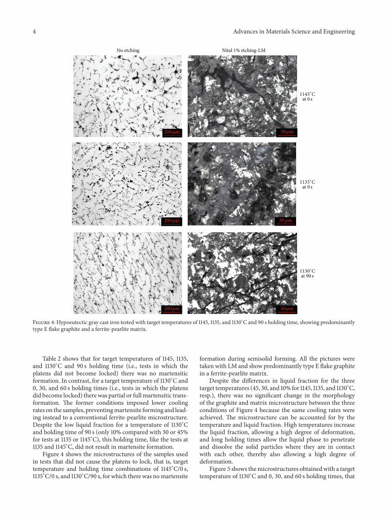
Figure 4: Hypoeutectic gray cast iron tested with target temperatures of 1145, 1135, and 1130∘C and 90 s holding time, showing predominantlytype E flake graphite and a ferrite-pearlite matrix.
Table 2 shows that for target temperatures of 1145, 1135,and 1130∘C and 90 s holding time (i.e., tests in which theplatens did not become locked) there was no martensiticformation. In contrast, for a target temperature of 1130∘C and0, 30, and 60 s holding times (i.e., tests in which the platensdid become locked) therewas partial or fullmartensitic trans-formation. The former conditions imposed lower coolingrates on the samples, preventingmartensite forming and lead-ing instead to a conventional ferrite-pearlite microstructure.Despite the low liquid fraction for a temperature of 1130∘Cand holding time of 90 s (only 10% compared with 30 or 45%for tests at 1135 or 1145∘C), this holding time, like the tests at1135 and 1145∘C, did not result in martensite formation.
Figure 4 shows the microstructures of the samples usedin tests that did not cause the platens to lock, that is, targettemperature and holding time combinations of 1145∘C/0 s,1135∘C/0 s, and 1130∘C/90 s, for which therewas nomartensite
formation during semisolid forming. All the pictures weretaken with LM and show predominantly type E flake graphitein a ferrite-pearlite matrix.
Despite the differences in liquid fraction for the threetarget temperatures (45, 30, and 10% for 1145, 1135, and 1130∘C,resp.), there was no significant change in the morphologyof the graphite and matrix microstructure between the threeconditions of Figure 4 because the same cooling rates wereachieved. The microstructure can be accounted for by thetemperature and liquid fraction. High temperatures increasethe liquid fraction, allowing a high degree of deformation,and long holding times allow the liquid phase to penetrateand dissolve the solid particles where they are in contactwith each other, thereby also allowing a high degree ofdeformation.
Figure 5 shows themicrostructures obtainedwith a targettemperature of 1130∘C and 0, 30, and 60 s holding times, that

Advances in Materials Science and Engineering 5
No etching Nital 1% etching-LM Nital 1% etching-SEM
1130∘Cat 60 s
1130∘Cat 30 s
at 0 s1130∘C
50𝜇m 5𝜇m
5𝜇m
5𝜇m
50𝜇m
50𝜇m
200𝜇m
200𝜇m
200𝜇m
Figure 5: Hypoeutectic gray cast iron tested with a target temperature of 1130∘C and 0, 30, and 60 s holding times, showing predominantlytype E flake graphite and martensite in a ferrite-pearlite matrix.
is, tests in which martensite formed during semisolid form-ing. Samples tested at 1130∘C and 0 s holding time exhibitedpartial martensitic transformation and martensite coloniessurrounded by a ferrite-pearlite matrix, while samples testedat 1130∘C and 30 and 60 s holding times exhibited fullmarten-sitic transformation. In fact, to obtain a full martensiticstructure a short holding time is required, probably withinthe 30/60 s interval, because aminimum time at the semisolidtemperature range is required to homogenize the temperaturethroughout the sample.
The change from the type A flake graphite in the originalraw material to the type E flake graphite in the semisolidcompressed samples is explained by the faster cooling rate.When the raw material cools slowly, the graphite can spreadaround the edges of the grain. In contrast, when cooling takesplace faster, whether the sample is stuck to the AISI H13steel platen or not, there is very little time for diffusion tooccur and type E graphite to form. Like type A flake graphite,type E is recommended for a wide range of applications,particularly those that require good wear resistance. TypeA is characterized by a uniform distribution and randomorientation; it has intermediate-sized flakes and is typicallythe result of moderate cooling rates. Type E, in contrast,
is characterized by interdendritic segregation, which has apreferred rather than a random orientation, and is typicallythe result of high cooling rates and has fine flakes, potentiallyincreasing the need for machining and surface finishing [14].
It is also worth noting that the increase in stress duringthixoforming was not enough by itself to producemartensite.Although more stress is required to form a sample with alower liquid content, the hot-compressed sample with only10% liquid content (1130∘C at 90 s) had the same morpholog-ical features as the sampleswith 30 or 45% liquid content (1135or 1145∘C). This indicates that the main factor influencingmartensitic transformation in this alloy in these specificsituations was cooling rate rather than stress. To evaluatethe structure of the samples quantitatively, the parametersgraphite content, interdendritic arm spacing (IAS, whichis equivalent to grain size), and graphite flake length weremeasured. The results can be seen in Table 3.
As shown in Table 3, graphite content, IAS, and graphiteflake length were statistically equivalent for all the samplesunder all the conditions evaluated. Achieving morphologicalstability in the semisolid state is, from an industrial perspec-tive, the main goal of this type of processing and the maincharacteristic required for alloys used for this purpose.

6 Advances in Materials Science and Engineering
Table 3: Quantitative metallographic analysis of alloys (95% confidence interval).
Condition Predominant type of graphite Graphite (%) IAS (𝜇m) Graphite flake length (𝜇m)As-cast A 7.5 ± 0.8 59.1 ± 43.8 57.5 ± 38.91145∘C E 8.6 ± 0.7 57.8 ± 19.7 33.1 ± 9.61135∘C E 8.8 ± 1.1 58.1 ± 22.5 32.5 ± 6.91300∘C–0 s E 9.5 ± 0.8 45.2 ± 15.4 25.2 ± 8.61300∘C–30 s E 10.1 ± 0.7 43.9 ± 16.1 22.9 ± 9.31300∘C–60 s E 9.8 ± 1.4 42.9 ± 16.6 25.3 ± 6.81300∘C–90 s E 10.3 ± 1.6 53.1 ± 24.1 31.3 ± 8.5
Table 4: Vickers microhardness for alloys (95% confidence inter-val).
Condition Predominant phase Vickers microhardness (HV)1145∘C Ferrite/pearlite 331.3 ± 31.61135∘C 325.1 ± 36.7
1130∘C–0 s Ferrite/pearlite 379.5 ± 39.9Martensite colonies 577.8 ± 34.6
1130∘C–30 s Martensite 593.6 ± 41.91130∘C–60 s Martensite 555.3 ± 39.31130∘C–90 s Ferrite/pearlite 329.3 ± 30.2
The results of the Vickers microhardness tests are shownin Table 4. For the ferrite-pearlite matrix, microhardnessvalues were of the order of 325 to 377HV. However, as a95% confidence interval was used, they are all statisticallyequivalent. Values for the martensitic matrix ranged from555 to 593HV and were all also statistically equivalent. Thelatter values are 60% higher than those for the ferrite-pearlitesamples, showing that martensite transformation occurredin samples that stuck to the platens during hot-compressiontests. For samples heated to 1130∘C and subjected to aholding time of 0 s, the microhardness was measured in eachphase (ferrite-pearlite and martensite) and was equal to thevalues for the same phases in samples subjected to the otherconditions.
Although with a 95% confidence interval there is nostatistically significant variation in the graphite content, IAS,and graphite flake length for the different target temperaturesand holding times tested, the IAS and mean graphite flakelength show a slight tendency to decrease in martensiticmicrostructures. In contrast, there is a statistically significantincrease in Vickersmicrohardness inmartensiticmicrostruc-tures, due to this phase being much harder than ferrite andpearlite—so in this case, the IAS and graphite length areobviously not the main reason for increase in hardness.
Finally, in terms of an industrial context, thixoformingwith the platens locked is equivalent to semisolid stateclosed die casting. The main parameter influencing marten-site formation in this situation is the high cooling rate,which is a basic characteristic of injection processes. Theexperiment with the platens lockedwas intended to show thatconventional die casting generates a partially or completelymartensitic microstructure that is the result of thermaltransformation rather than being stress-induced.
The final microstructure can therefore be controlled bycontrolling the cooling rate. When a structure with highmechanical strength and hardness is required and toughnessis not an issue, the platens can be used at a conventionaltemperature of 200/250∘C as in this study. If a microstructurewith minimum fracture toughness is required, higher tem-peratures can be used to reduce the cooling rate and generatea pearlitic or pearlitic-ferritic microstructure or, dependingon the cooling rate achieved, a mixture of martensite onthe surface and pearlite and ferrite on the inside. Once themartensitic transformation generally occurs only at outerregions of the thixoformed part while inner regions preservethe conventional gray cast iron morphology (as presentedin Figure 1) the thixoforming of gray cast iron could besuitable formanufacturing of parts that require a hard surfaceand relatively ductile core-like axles and gears. In this waythe necessary microstructure can be achieved to ensure thatthe part has the required in-service performance, somethingthat is very difficult or almost impossible to achieve inconventional casting.
4. Conclusions
This work aimed to identify the conditions required toproduce martensitic structures in hypoeutectic gray cast ironat 3.1% CE (carbon equivalent) with a high solid contentseverely deformed in the semisolid state in hot-compressiontests. The main conclusions were as follows:
(i) A hot-compressed sample with only 10% liquid con-tent (1130∘C and 90 s) had the same morphologicalfeatures as hot-compressed samples with 30 or 45%liquid content (1135 or 1145∘C) even though greaterstress is required to form a sample with three to fourtimes less liquid. This indicates that the main factorinfluencing martensitic transformation in this alloyunder these specific conditions is the cooling raterather than stress.
(ii) The key to the formation of martensite was the highercooling rates for the samples that stuck to the platens.Vickers microhardness measurements showed thatthe hardness in martensitic regions was of the orderof 60% greater than in ferrite-pearlite regions.
(iii) All samples presented predominantly type E flakegraphite and graphite content, IAS, and graphite flakelength were statistically equivalent for all the samples

Advances in Materials Science and Engineering 7
under all the conditions evaluated. From an industrialperspective, this morphological homogeneity duringthe semisolid state is the main goal of thixoformingand themain characteristic required in alloys used forthis purpose.
Conflict of Interests
The authors declare that there is no conflict of interestsregarding the publication of this paper.
Acknowledgments
The authors would like to thank Grant 2011/19997-0 fromSao Paulo Research Foundation (FAPESP), National Councilfor Scientific and Technological Development (CNPq), andGrant 095/2010 from Coordination for the Improvement ofHigher Education Personnel (CAPES) for financial supportand Faculty of Mechanical Engineering, State University ofCampinas, for providing the necessary infrastructure.
References
[1] G.Hirt and R. Koop,Thixoforming—SemisolidMetal Processing,Wiley-VCH, Weinheim, Germany, 2009.
[2] D. H. Kirkwood, M. Suery, P. Kapranos, H. V. Atkinson, andK. P. Young, Semisolid Processing of Alloys, Springer, Berlin,Germany, 2010.
[3] S. Sugiyama, J. Li, and J. Yanagimoto, “Semisolid extrusion oflow-carbon steel,”Materials Transactions, vol. 48, no. 4, pp. 807–812, 2007.
[4] J. C. Pierret, A. Rassili, G. Vaneetveld, and J. Lecomte-Beckers,“Stability of steel thixoforming process,” Transactions of Nonfer-rous Metals Society of China, vol. 20, no. 3, pp. s937–s942, 2010.
[5] A. Rassili and H. V. Atkinson, “A review on steel thixoforming,”Transactions of Nonferrous Metals Society of China, vol. 20,supplement 3, pp. s1048–s1054, 2010.
[6] M. Tsuchiya, H. Ueno, and I. Takagi, “Research of semi solidcasting of iron,” JSAE Review, vol. 24, no. 2, pp. 205–214, 2003.
[7] H. Nomura, P. Qiu, M. Takita, and N. Poolthong, “Semi-solidprocessing of cast iron,” Materials Transactions, vol. 42, no. 2,pp. 303–308, 2001.
[8] J. Cui, H. Zhang, L. Chen, H. Li, and W. Tong, “Microstructureand mechanical properties of a wear-resistant as-cast alloyedbainite ductile iron,” Acta Metallurgica Sinica, vol. 27, no. 3, pp.476–482, 2014.
[9] F. Pahlevani and M. Nili-Ahmadabadi, “Development of semi-solid ductile cast iron,” International Journal of Cast MetalsResearch, vol. 17, no. 3, pp. 157–161, 2004.
[10] M. Ramadan, N. El-Bagoury, N. Fathy, M. A. Waly, and A. A.Nofal, “Microstructure, fluidity, and mechanical properties ofsemi-solid processed ductile iron,” Journal of Materials Science,vol. 46, no. 11, pp. 4013–4019, 2011.
[11] M. Ramadan, M. Takita, and H. Nomura, “Effect of semi-solidprocessing on solidification microstructure and mechanicalproperties of gray cast iron,” Materials Science and EngineeringA, vol. 417, no. 1-2, pp. 166–173, 2006.
[12] A. S. Roca, H. D. C. Fals, J. A. Pedron, and E. J. Zoqui,“Thixoformability of hypoeutectic gray cast iron,” Journal of
Materials Processing Technology, vol. 212, no. 6, pp. 1225–1235,2012.
[13] H. K. D. H. Bhadeshia, Worked Examples in the Geometry ofCrystals, The Institute of Metals, London, UK, 2001.
[14] C. V. White, “Gray iron,” in ASM Handbook, Properties andSelection: Irons, Steels and High-Performance Alloys, pp. 38–42,ASM International, Novelty, Ohio, USA, 1993.

Submit your manuscripts athttp://www.hindawi.com
ScientificaHindawi Publishing Corporationhttp://www.hindawi.com Volume 2014
CorrosionInternational Journal of
Hindawi Publishing Corporationhttp://www.hindawi.com Volume 2014
Polymer ScienceInternational Journal of
Hindawi Publishing Corporationhttp://www.hindawi.com Volume 2014
Hindawi Publishing Corporationhttp://www.hindawi.com Volume 2014
CeramicsJournal of
Hindawi Publishing Corporationhttp://www.hindawi.com Volume 2014
CompositesJournal of
NanoparticlesJournal of
Hindawi Publishing Corporationhttp://www.hindawi.com Volume 2014
Hindawi Publishing Corporationhttp://www.hindawi.com Volume 2014
International Journal of
Biomaterials
Hindawi Publishing Corporationhttp://www.hindawi.com Volume 2014
NanoscienceJournal of
TextilesHindawi Publishing Corporation http://www.hindawi.com Volume 2014
Journal of
NanotechnologyHindawi Publishing Corporationhttp://www.hindawi.com Volume 2014
Journal of
CrystallographyJournal of
Hindawi Publishing Corporationhttp://www.hindawi.com Volume 2014
The Scientific World JournalHindawi Publishing Corporation http://www.hindawi.com Volume 2014
Hindawi Publishing Corporationhttp://www.hindawi.com Volume 2014
CoatingsJournal of
Advances in
Materials Science and EngineeringHindawi Publishing Corporationhttp://www.hindawi.com Volume 2014
Smart Materials Research
Hindawi Publishing Corporationhttp://www.hindawi.com Volume 2014
Hindawi Publishing Corporationhttp://www.hindawi.com Volume 2014
MetallurgyJournal of
Hindawi Publishing Corporationhttp://www.hindawi.com Volume 2014
BioMed Research International
MaterialsJournal of
Hindawi Publishing Corporationhttp://www.hindawi.com Volume 2014
Nano
materials
Hindawi Publishing Corporationhttp://www.hindawi.com Volume 2014
Journal ofNanomaterials