research article numerical prediction of hydromechanical...
TRANSCRIPT
Research ArticleNumerical Prediction of Hydromechanical Behaviour ofControllable Pitch Propeller
Saman Tarbiat, Hassan Ghassemi, and Manouchehr Fadavie
Department of Ocean Engineering, Amirkabir University of Technology, Tehran, Iran
Correspondence should be addressed to Hassan Ghassemi; [email protected]
Received 14 January 2014; Revised 10 April 2014; Accepted 14 April 2014; Published 9 July 2014
Academic Editor: Sergio Preidikman
Copyright © 2014 Saman Tarbiat et al. This is an open access article distributed under the Creative Commons Attribution License,which permits unrestricted use, distribution, and reproduction in any medium, provided the original work is properly cited.
The research described in this paper was carried out to predict hydrodynamic and frictional forces of controllable pitch propeller(CPP) that bring about fretting problems in a blade bearing.The governing equations are Reynolds-averagedNavier-Stokes (RANS)and are solved by OpenFOAM solver for hydrodynamic forces behind the ship’s wake. Frictional forces are calculated by practicalmechanical formulae. Different advance velocities with constant rotational speed for blades are used to achieve hydrodynamiccoefficients in open water and the wake behind the propeller. Results are compared at four different pitches. Detailed numericalresults of 3D modelling of the propeller, hydrodynamic characteristics, and probability of the fretting motion in the propeller arepresented. Results show that the probability of the fretting movement is related to the pitch.
1. Introduction
The main goal of any propulsion system is to obtain therequired speed of a vessel. One way to increase the control,manoeuvrability, and efficiency is to utilize controllable pitchpropellers instead of constant pitch ones. Specific character-istics of controllable propellers permit the blades to rotatearound the propeller axle. Blades rotate with complex mech-anismwhich acts mechanically or hydraulically.The ability ofthe CPP is to adjust the pitch in order to avoid themotor to beoverloaded and lead to a decrease in shaft speed as well as toincrease the motor duration. During recent years numerousinvestigations have been carried out on propeller designs.Consequently different methods have been presented.
Because of different application of propellers numerouslayouts of propeller have emerged. Today CPP is used espe-cially on vessels which operate at various operation condi-tions such as containers, fishing vessels, and towing vessels.For the first time in 1840 CPP was introduced. At that timepractical usage of CPP was in gas turbines. In twentieth cen-turywhen diesel was introduced, usage of CPP increased sud-denly. At that time pitch control was simple and mechanical.Dutch Schoonerwas the first onewho appliedCPP for diesels.In 1934, Escher Wyss used hydraulic mechanism in CPPwhich can be used for larger vessels. In 1937, Kamewa
propellers were introduced. The hub mechanism of thementioned propellers was based on Kaplan turbine design[1, 2].
In recent years numerous researches have been conductedon mechanism and the controlling system of CPP and on theways to decrease the friction resistance and vibrations of theblades. Tendency to increase both hydrodynamic forces inCPP and usage of hydraulic systems for pitch adjustmentleads to more investigations on CPP. For example, in 2005,Bakker studied different control strategies. He introducedmechanical systems of CPP propellers in detail [3]. In 2006,Dallinga calculated the forces acting on the CPP in differentsea conditions [4]. In 2009, Stuart et al. calculated the forcesacting on blades under cavitation condition [5]. A wakemodel for the prediction of propeller performance at lowadvance ratios was investigated by Tian and Kinnas [6]. In2009, Godjevac et al. [7] focused on the forces acting in a con-trollable pitch propeller, mechanism, and the manifestationof vibrating motion (fretting) in a blade bearing caused byseaway.
Fretting is a special wear process which happens in con-tact surfaces which have a relative oscillatory motion of smallamplitude, typically smaller than 1mm.Usually, themotion iscaused by vibrations of the machinery. The fretting wear canoccur at the CPP of the contact between blades and hub due
Hindawi Publishing CorporationInternational Journal of Rotating MachineryVolume 2014, Article ID 180725, 7 pageshttp://dx.doi.org/10.1155/2014/180725
2 International Journal of Rotating Machinery
Blade foot
Radial part
Axial part
Blade carrier
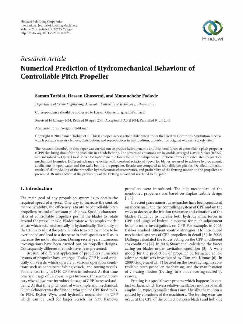
Figure 1: CPP configuration and its coordinate system [8].
to variable hydrodynamic loading acting on the blades. Thecritical moment for the commencement of fretting motion iswhen the spindle torque conquers the friction torque. As thethrust and torque of a blade change during one revolution, theCoulomb friction in the blade bearing alters as well duringone revolution. Looking at the Coulomb friction in the bladebearing and spindle torque of the corresponding blade, itis possible to illustrate the occurrence of fretting motion.Figure 1 shows the CPP configurations and its coordinate sys-tem. Blade bearing is the bearing that connects the blade foot,blade carrier, and hub. Blade bearing has the radial and axialparts. Radial part of blade bearing has the inner side (closerto x-axis) and outer side [8].
The 𝑥-, 𝑦-, and 𝑧-axes are used to explain the forces andmoments acting in a blade bearing. It also shows the radialand axial part of the blade bearing. The blade foot and theblade carrier are fastened with bolts. The critical moment forthe beginning of fretting motion is when the spindle torqueovercomes the friction torque. As the thrust and torque of ablade change during one revolution, the friction force in theblade bearing changes as well during one revolution. Lookingat the friction force in the blade bearing and spindle torque ofthe corresponding blade, it is possible to illustrate the hap-pening of fretting motion.
The efficiency of the propulsion system is strongly depen-dent on propeller performance, thrust force, torque of pro-peller, and its efficiency. Therefore this study focuses onthe hydrodynamic performance and prediction of frettingmotion in special CPP.The purpose of this study is to identifythe effect of changes in pitch on propeller fretting motion.
Therefore, a simple method has been investigated tograph the propeller hydrodynamic coefficients with respect toadvance coefficient and fretting occurring during one revo-lution of the blades.This investigation considers the situationthat leads to fretting motion. When the hydrodynamic forceschange during rotation of the blades, the friction in the bladebearings will change accordingly. By calculation of the fric-tion in the blade bearing and spindle torque of the corre-sponding blade, it is possible to describe the occurrence offretting motion.
2. Three-Dimension Modelling ofthe Investigated Propeller
B-series propeller is a famous series which is used in almostall practical usages [1]. Pitch-diameter ratio in these series is
Flow
D3D
10D 2D
direction
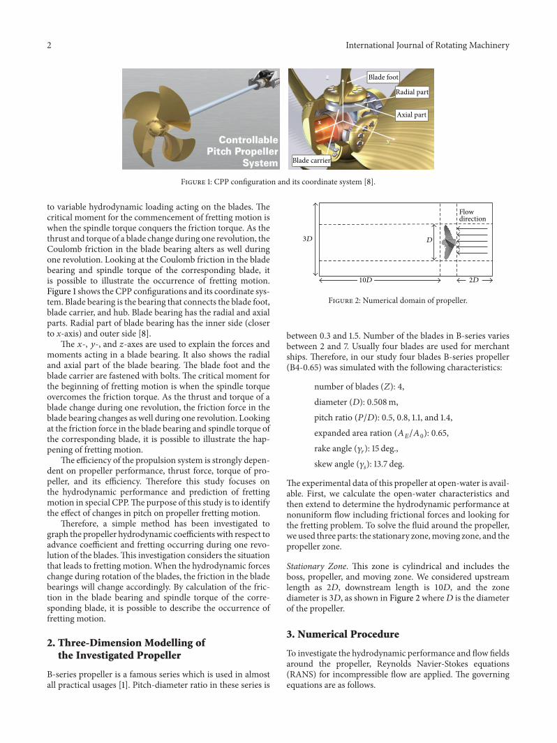
Figure 2: Numerical domain of propeller.
between 0.3 and 1.5. Number of the blades in B-series variesbetween 2 and 7. Usually four blades are used for merchantships. Therefore, in our study four blades B-series propeller(B4-0.65) was simulated with the following characteristics:
number of blades (𝑍): 4,diameter (𝐷): 0.508m,pitch ratio (𝑃/𝐷): 0.5, 0.8, 1.1, and 1.4,expanded area ration (𝐴
𝐸/𝐴0): 0.65,
rake angle (𝛾𝑟): 15 deg.,
skew angle (𝛾𝑠): 13.7 deg.
The experimental data of this propeller at open-water is avail-able. First, we calculate the open-water characteristics andthen extend to determine the hydrodynamic performance atnonuniform flow including frictional forces and looking forthe fretting problem. To solve the fluid around the propeller,we used three parts: the stationary zone,moving zone, and thepropeller zone.
Stationary Zone. This zone is cylindrical and includes theboss, propeller, and moving zone. We considered upstreamlength as 2𝐷, downstream length is 10𝐷, and the zonediameter is 3𝐷, as shown in Figure 2 where𝐷 is the diameterof the propeller.
3. Numerical Procedure
To investigate the hydrodynamic performance and flow fieldsaround the propeller, Reynolds Navier-Stokes equations(RANS) for incompressible flow are applied. The governingequations are as follows.
International Journal of Rotating Machinery 3
Figure 3: Final mesh for the calculation domain.
Conservation of mass (quantity equation):
𝜕𝜌
𝜕𝑡
+
𝜕
𝜕𝑥𝑗
(𝜌𝑢𝑗) = 0, (1)
conservation of momentum:
𝜕𝜌
𝜕𝑡
(𝜌𝑢𝑖) +
𝜕
𝜕𝑥𝑗
(𝜌𝑢𝑖𝑢𝑗)
=
𝜕
𝜕𝑥𝑗
[−𝑝𝛿𝑖𝑗+ 𝜇(
𝜕𝑈𝑖
𝜕𝑋𝑗
+
𝜕𝑈𝐽
𝜕𝑋𝑖
)] + 𝐵𝑖,
(2)
where 𝐵𝑖= body force.
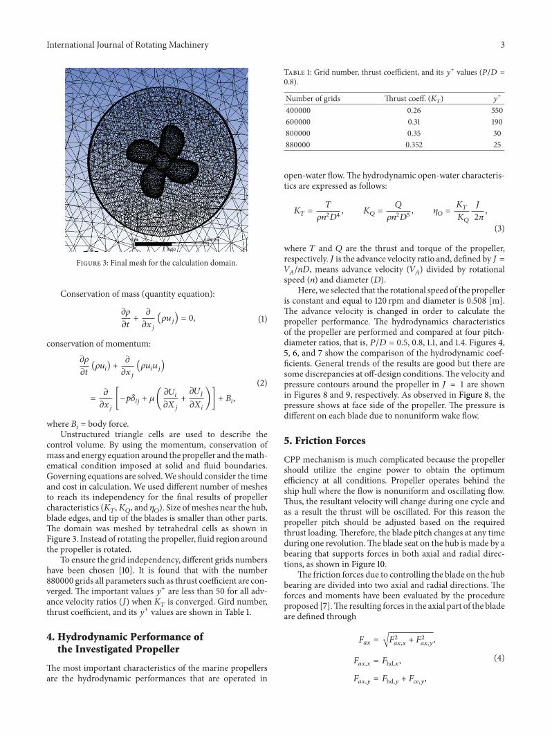
Unstructured triangle cells are used to describe thecontrol volume. By using the momentum, conservation ofmass and energy equation around the propeller and themath-ematical condition imposed at solid and fluid boundaries.Governing equations are solved.We should consider the timeand cost in calculation. We used different number of meshesto reach its independency for the final results of propellercharacteristics (𝐾
𝑇,𝐾𝑄, and 𝜂
𝑂). Size of meshes near the hub,
blade edges, and tip of the blades is smaller than other parts.The domain was meshed by tetrahedral cells as shown inFigure 3. Instead of rotating the propeller, fluid region aroundthe propeller is rotated.
To ensure the grid independency, different grids numbershave been chosen [10]. It is found that with the number880000 grids all parameters such as thrust coefficient are con-verged. The important values 𝑦+ are less than 50 for all adv-ance velocity ratios (𝐽) when 𝐾
𝑇is converged. Gird number,
thrust coefficient, and its 𝑦+ values are shown in Table 1.
4. Hydrodynamic Performance ofthe Investigated Propeller
The most important characteristics of the marine propellersare the hydrodynamic performances that are operated in
Table 1: Grid number, thrust coefficient, and its 𝑦+ values (𝑃/𝐷 =
0.8).
Number of grids Thrust coeff. (𝐾𝑇) 𝑦
+
400000 0.26 550600000 0.31 190800000 0.35 30880000 0.352 25
open-water flow.The hydrodynamic open-water characteris-tics are expressed as follows:
𝐾𝑇=
𝑇
𝜌𝑛2𝐷4, 𝐾
𝑄=
𝑄
𝜌𝑛2𝐷5, 𝜂
𝑂=
𝐾𝑇
𝐾𝑄
𝐽
2𝜋
,
(3)
where 𝑇 and 𝑄 are the thrust and torque of the propeller,respectively. 𝐽 is the advance velocity ratio and, defined by 𝐽 =𝑉𝐴/𝑛𝐷, means advance velocity (𝑉
𝐴) divided by rotational
speed (𝑛) and diameter (𝐷).Here, we selected that the rotational speed of the propeller
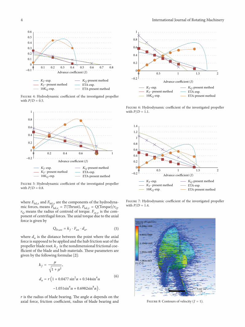
is constant and equal to 120 rpm and diameter is 0.508 [m].The advance velocity is changed in order to calculate thepropeller performance. The hydrodynamics characteristicsof the propeller are performed and compared at four pitch-diameter ratios, that is, 𝑃/𝐷 = 0.5, 0.8, 1.1, and 1.4. Figures 4,5, 6, and 7 show the comparison of the hydrodynamic coef-ficients. General trends of the results are good but there aresome discrepancies at off-design conditions.The velocity andpressure contours around the propeller in 𝐽 = 1 are shownin Figures 8 and 9, respectively. As observed in Figure 8, thepressure shows at face side of the propeller. The pressure isdifferent on each blade due to nonuniform wake flow.
5. Friction Forces
CPP mechanism is much complicated because the propellershould utilize the engine power to obtain the optimumefficiency at all conditions. Propeller operates behind theship hull where the flow is nonuniform and oscillating flow.Thus, the resultant velocity will change during one cycle andas a result the thrust will be oscillated. For this reason thepropeller pitch should be adjusted based on the requiredthrust loading.Therefore, the blade pitch changes at any timeduring one revolution.The blade seat on the hub is made by abearing that supports forces in both axial and radial direc-tions, as shown in Figure 10.
The friction forces due to controlling the blade on the hubbearing are divided into two axial and radial directions. Theforces and moments have been evaluated by the procedureproposed [7].The resulting forces in the axial part of the bladeare defined through
𝐹𝑎𝑥
= √𝐹2
𝑎𝑥,𝑥+ 𝐹2
𝑎𝑥,𝑦,
𝐹𝑎𝑥,𝑥
= 𝐹hd,𝑥,
𝐹𝑎𝑥,𝑦
= 𝐹hd,𝑦 + 𝐹ce,𝑦,
(4)
4 International Journal of Rotating Machinery
00.10.20.30.40.50.6
0 0.1 0.2 0.3 0.4 0.5 0.6 0.7 0.8Advance coefficient (J)−0.1
KT-exp.KT- present method10KQ-exp.
KQ-present methodETA-exp.ETA-present method
Figure 4: Hydrodynamic coefficient of the investigated propellerwith 𝑃/𝐷 = 0.5.
0
0.2
0.4
0.6
0.8
1
0 0.2 0.4 0.6 0.8 1
Advance coefficient (J)−0.2
KT-exp.KT- present method10KQ-exp.
KQ-present methodETA-exp.ETA-present method
Figure 5: Hydrodynamic coefficient of the investigated propellerwith 𝑃/𝐷 = 0.8.
where 𝐹hd,𝑥 and 𝐹hd,𝑦 are the components of the hydrodyna-mic forces, means 𝐹hd,𝑥 = 𝑇(Thrust), 𝐹hd,𝑦 = 𝑄(Torque)/𝑟
𝑄.
𝑟𝑄means the radius of centroid of torque. 𝐹ce,𝑦 is the com-
ponent of centrifugal forces. The axial torque due to the axialforce is given by
𝑄Fr,𝑎𝑥 = 𝑘𝑓⋅ 𝐹𝑎𝑥
⋅ 𝑑𝑎, (5)
where 𝑑𝑎is the distance between the point where the axial
force is supposed to be applied and the hub friction seat of thepropeller blade root. 𝑘
𝑓is the nondimensional frictional coe-
fficient of the blade and hub materials. These parameters aregiven by the following formulae [2]:
𝑘𝑓=
𝜇
√1 + 𝜇2
,
𝑑𝑎= 𝑟 (1 + 0.0477 sin2𝛼 + 0.544sin4𝛼
−1.051sin6𝛼 + 0.6982sin8𝛼) .
(6)
𝑟 is the radius of blade bearing. The angle 𝛼 depends on theaxial force, friction coefficient, radius of blade bearing and
0
0.2
0.4
0.6
0.8
1
0 0.5 1 1.5 2
Advance coefficient (J)−0.2
KT-exp.KT- present method10KQ-exp.
KQ-present methodETA-exp.ETA-present method
Figure 6: Hydrodynamic coefficient of the investigated propellerwith 𝑃/𝐷 = 1.1.
0
0.2
0.4
0.6
0.8
1
1.2
1.4
0 0.5 1 1.5 2
KT-exp.KT- present method10KQ-exp.
KQ-present methodETA-exp.ETA-present method
Advance coefficient (J)−0.2
Figure 7: Hydrodynamic coefficient of the investigated propellerwith 𝑃/𝐷 = 1.4.
Figure 8: Contours of velocity (𝐽 = 1).

International Journal of Rotating Machinery 5
Figure 9: Pressure contour on suction surface (𝐽 = 1).
Blade seatPin
Piston head
Cylinder chambers
Oil pipelines
(a)
Radial part
Axial part
(b)
Figure 10: Main element inside a CPP hub (a). Blade seat (b) [9].
radius of blade carrier, thickness of blade bearing, andYoung’s modulus of elasticity. Here, the value of frictioncoefficient (𝜇) is about 0.1 and 𝛼 is approximately 170 [deg.]and they are chosen for present calculations.
In the radial part the moments are given by
𝑀𝑎𝑥
= √𝑀2
𝑎𝑥,𝑥+𝑀2
𝑎𝑥,𝑦,
𝑀𝑎𝑥,𝑥
= −𝑀hd,𝑥,
𝑀𝑎𝑥,𝑦
= 𝑀hd,𝑦 +𝑀ce,𝑦,
(7)
where 𝑀hd,𝑥 and 𝑀hd,𝑦 are the components of the hydrody-namic moments and 𝑀ce,𝑦 is the component of centrifugalmoments. The hydrodynamic moments acting on the centreof hydrodynamic (CH) of a CPP blade are calculated by
𝑀hd,𝑥 = (
𝑄
𝑟𝑄
) ⋅ 𝑧CH,
𝑀hd,𝑦 = 𝑇 ⋅ 𝑧CH,
𝑀hd,𝑧 = 𝑇 ⋅ 𝑦CH + (
𝑄
𝑟𝑄
) ⋅ 𝑥CH,
(8)
where (𝑥CH, 𝑦CH, 𝑧CH) is the hydrodynamic force centre.Finally, the friction torque in the radial part of the bladebearing is expressed as [11]
𝑄Fr,rad =4
𝜋
⋅ 𝜇 ⋅ 𝑀𝑎𝑥(cosΦ
0+ 𝑢 ⋅ arcsin (𝑢)) , (9)
where 𝑢 is a coefficient that describes the ratio of the radialforce and the maximum force resulting from the bendingmoment and Φ
0is the angle of circumference around blade
bearing. Total friction torque of the blade bearing is obtainedby 𝑄Fr = √𝑄
2
Fr,𝑎𝑥 + 𝑄2
Fr,rad.The fretting motion will happen when the blade spindle
torque becomes higher than the friction torque, whichmeans𝑀hd,𝑧 > 𝑄Fr.
6. Results and Discussion
Fretting motion starts when the sum of the forces acting onthe body overcomes the friction force. As mentioned, it mayoccur when the blade spindle torque becomes bigger than thefriction torque. In order to investigate the start of the frettingmotion in a CPP, the relation between friction torque and thespindle torque during one revolution was accomplished.
In this study, we focused on the effect of different pitcheson fretting behaviour of the CPP. Propeller is working inbehind the ship hull where the wake flow which is into thepropeller is nonuniform and oscillating flow. Wake factor(1 − 𝑤) is defined by 𝑉
𝐴/𝑉𝑆, where 𝑉
𝐴is advance velocity
behind the ship and 𝑉𝑆is the speed of the ship. Due to
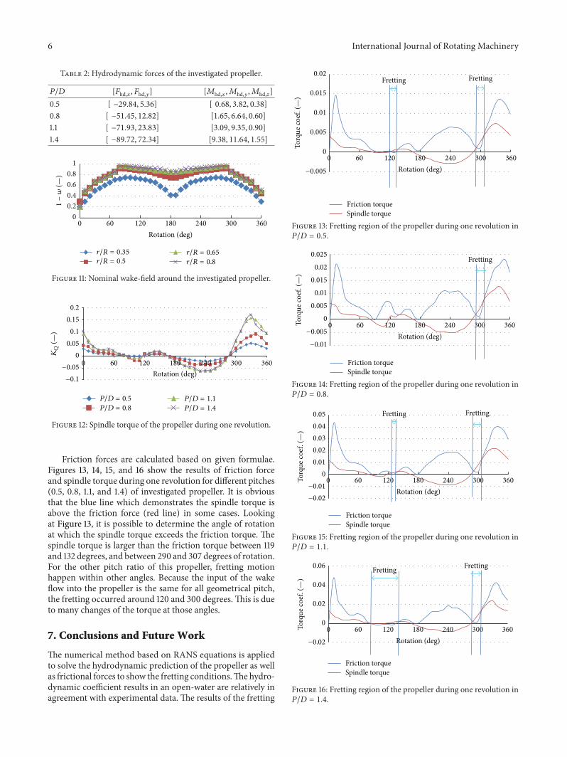
oscillating wake filed, the hydrodynamic forces will change inthe wake field behind the propeller. The investigated wakefield (1 − 𝑤) during one revolution of the blades showsdifferent radius of the blades in Figure 11. The results of thespindle torque coefficient for different pitches for one rev-olution are presented in Figure 12. The mean values of thehydrodynamic Forces are presented in nondimensional val-ues in Table 2.
6 International Journal of Rotating Machinery
Table 2: Hydrodynamic forces of the investigated propeller.
𝑃/𝐷 [𝐹hd,𝑥, 𝐹hd,𝑦] [𝑀hd,𝑥,𝑀hd,𝑦,𝑀hd,𝑧]
0.5 [ −29.84, 5.36] [ 0.68, 3.82, 0.38]
0.8 [ −51.45, 12.82] [1.65, 6.64, 0.60]
1.1 [ −71.93, 23.83] [3.09, 9.35, 0.90]
1.4 [ −89.72, 72.34] [9.38, 11.64, 1.55]
00.20.40.60.8
1
0 60 120 180 240 300 360Rotation (deg)
1−w
(—)
r/R = 0.35
r/R = 0.5
r/R = 0.65
r/R = 0.8
Figure 11: Nominal wake-field around the investigated propeller.
Rotation (deg)0 60 120 180 240 300 360
0.2
0.15
0.1
0.05
0
−0.05
−0.1
KQ
(—)
P/D = 0.5
P/D = 0.8
P/D = 1.1
P/D = 1.4
Figure 12: Spindle torque of the propeller during one revolution.
Friction forces are calculated based on given formulae.Figures 13, 14, 15, and 16 show the results of friction forceand spindle torque during one revolution for different pitches(0.5, 0.8, 1.1, and 1.4) of investigated propeller. It is obviousthat the blue line which demonstrates the spindle torque isabove the friction force (red line) in some cases. Lookingat Figure 13, it is possible to determine the angle of rotationat which the spindle torque exceeds the friction torque. Thespindle torque is larger than the friction torque between 119and 132 degrees, and between 290 and 307 degrees of rotation.For the other pitch ratio of this propeller, fretting motionhappen within other angles. Because the input of the wakeflow into the propeller is the same for all geometrical pitch,the fretting occurred around 120 and 300 degrees. This is dueto many changes of the torque at those angles.
7. Conclusions and Future Work
The numerical method based on RANS equations is appliedto solve the hydrodynamic prediction of the propeller as wellas frictional forces to show the fretting conditions.Thehydro-dynamic coefficient results in an open-water are relatively inagreement with experimental data. The results of the fretting
Rotation (deg)
0
0.005
0.01
0.015
0.02
0 60 120 180 240 300 360
Friction torqueSpindle torque
Fretting Fretting
−0.005
Torq
ue co
ef. (
—)
Figure 13: Fretting region of the propeller during one revolution in𝑃/𝐷 = 0.5.
0
0.005
0.01
0.015
0.02
0.025
0 60 120 180 240 300 360
Fretting
Friction torqueSpindle torque
Rotation (deg)−0.005
−0.01
Torq
ue co
ef. (
—)
Figure 14: Fretting region of the propeller during one revolution in𝑃/𝐷 = 0.8.
00.010.020.030.040.05
0 60 120 180 240 300 360
FrettingFretting
Friction torqueSpindle torque
Rotation (deg)−0.01
−0.02
Torq
ue co
ef. (
—)
Figure 15: Fretting region of the propeller during one revolution in𝑃/𝐷 = 1.1.
0
0.02
0.04
0.06
0 60 120 180 240 300 360
FrettingFretting
Friction torqueSpindle torque
Rotation (deg)−0.02
Torq
ue co
ef. (
—)
Figure 16: Fretting region of the propeller during one revolution in𝑃/𝐷 = 1.4.
International Journal of Rotating Machinery 7
behaviour of the propeller at different pitches for the investi-gated propeller are presented. It shows that for the currentpropeller, when pitch ratio increases, the possibility of thefretting motion increases.
In the near future, an investigation will be carried out ifthe geometry of this or other propellers is made available.Also, effect of the ocean wave may be studied on thefretting problem. More accurate formulae can be achieved todetermine the frictional forces on the blade bearing.
Conflict of Interests
The authors declare that there is no conflict of interestsregarding the publication of this paper.
Acknowledgments
This research was supported by the High Performance Com-puting Research Center (HPCRC) at Amirkabir Universityof Technology, which is acknowledged. The authors wish tothank the reviewers for their valuable comments and sugges-tion.
References
[1] J. S. Carlton, Marine Propellers and Propulsion, Butterworth-Heinemann, London, UK, 2nd edition, 2007.
[2] M.Martelli,M. Figari, andM.Altosole, “Controllable pitch pro-peller actuating mechanism, modeling and simulation,” Journalof Engineering for the Maritime Environment, vol. 227, 2013.
[3] J. Bakker, Dynamic behaviour and nonlinear aspects of the CPP[M.S. thesis], TU Delft, Delft, The Netherlands, 2005.
[4] R. P. Dallinga, “Bow flare slamming of container ships and it’simpact on operational reliability,” in Proceedings of the RoyalInstitution of Naval Architects International Conference—Designand Operation of Container Ships (RINA ’06), pp. 131–139,London, UK, November 2006.
[5] J. Stuart, M. Donnelly, and I. McClintock, “Measurements ofcontrollable pitch propeller blade loads under cavitating con-ditions,” in Proceedings of the 1st International Symposium onMarine Propulsors (SMP '09), Trondheim, Norway, June 2009.
[6] Y. Tian and S. A. Kinnas, “A wake model for the prediction ofpropeller performance at low advance ratios,” InternationalJournal of Rotating Machinery, vol. 2012, Article ID 372364, 11pages, 2012.
[7] M. Godjevac, T. van Beek, H. T. Grimmelius, T. Tinga, and D.Stapersma, “Prediction of frettingmotion in a controllable pitchpropeller during service,” Proceedings of the Institution of Mech-anical Engineers, vol. 223, no. 4, pp. 541–560, 2009.
[8] http://www.wartsila.com/en/propulsors/propellers/CPP.[9] http://www.rolls-royce.com/marine/products/propulsors/pro-
pellers/cpp/index.jsp.[10] R. Shamsi and H. Ghassemi, “Numerical investigation of yaw
angle effects on propulsive characteristics of podded propul-sors,” International Journal of Naval Architecture and OceanEngineering, vol. 5, no. 2, pp. 287–301, 2013.
[11] A. Faraz and S. Payandeh, “Towards approximated models ofCoulomb frictional moments,” Journal of Engineering Mathe-matics, vol. 40, no. 3, pp. 283–296, 2001.

International Journal of
AerospaceEngineeringHindawi Publishing Corporationhttp://www.hindawi.com Volume 2014
RoboticsJournal of
Hindawi Publishing Corporationhttp://www.hindawi.com Volume 2014
Hindawi Publishing Corporationhttp://www.hindawi.com Volume 2014
Active and Passive Electronic Components
Control Scienceand Engineering
Journal of
Hindawi Publishing Corporationhttp://www.hindawi.com Volume 2014
International Journal of
RotatingMachinery
Hindawi Publishing Corporationhttp://www.hindawi.com Volume 2014
Hindawi Publishing Corporation http://www.hindawi.com
Journal ofEngineeringVolume 2014
Submit your manuscripts athttp://www.hindawi.com
VLSI Design
Hindawi Publishing Corporationhttp://www.hindawi.com Volume 2014
Hindawi Publishing Corporationhttp://www.hindawi.com Volume 2014
Shock and Vibration
Hindawi Publishing Corporationhttp://www.hindawi.com Volume 2014
Civil EngineeringAdvances in
Acoustics and VibrationAdvances in
Hindawi Publishing Corporationhttp://www.hindawi.com Volume 2014
Hindawi Publishing Corporationhttp://www.hindawi.com Volume 2014
Electrical and Computer Engineering
Journal of
Advances inOptoElectronics
Hindawi Publishing Corporation http://www.hindawi.com
Volume 2014
The Scientific World JournalHindawi Publishing Corporation http://www.hindawi.com Volume 2014
SensorsJournal of
Hindawi Publishing Corporationhttp://www.hindawi.com Volume 2014
Modelling & Simulation in EngineeringHindawi Publishing Corporation http://www.hindawi.com Volume 2014
Hindawi Publishing Corporationhttp://www.hindawi.com Volume 2014
Chemical EngineeringInternational Journal of Antennas and
Propagation
International Journal of
Hindawi Publishing Corporationhttp://www.hindawi.com Volume 2014
Hindawi Publishing Corporationhttp://www.hindawi.com Volume 2014
Navigation and Observation
International Journal of
Hindawi Publishing Corporationhttp://www.hindawi.com Volume 2014
DistributedSensor Networks
International Journal of