research article numerical investigation on wheel-rail...
TRANSCRIPT
Research ArticleNumerical Investigation on Wheel-Rail Dynamic VibrationExcited by Rail Spalling in High-Speed Railway
Kaiyun Wang, Wanming Zhai, Kaikai Lv, and Zaigang Chen
State Key Laboratory of Traction Power, Southwest Jiaotong University, Chengdu 610031, China
Correspondence should be addressed to Kaiyun Wang; [email protected]
Received 1 March 2016; Accepted 5 May 2016
Academic Editor: Mario Terzo
Copyright © 2016 Kaiyun Wang et al. This is an open access article distributed under the Creative Commons Attribution License,which permits unrestricted use, distribution, and reproduction in any medium, provided the original work is properly cited.
Spalling in contact surface of rail is a typical form of rolling contact fatigue, which is a difficult problem to solve in railway. Oncethe spalling occurs in the rail, the wheel-rail dynamic interaction will become more severe. The wheel-rail dynamic interaction isinvestigated based on the theory of vehicle-track coupled dynamics in this paper, where the excitation modes of the rail spallingfailure are taken into consideration for high-speedwheel-rail system.Amodified excitationmodel of rail spalling failure is proposed.It can enable the investigations on two kinds of excitation modes in wheel-rail system due to the rail spalling, including the pulseand the harmonic excitation modes.The excitation mode can be determined by the ratio of the spalling length to its critical length.Thus, the characteristics of wheel-rail dynamic vibration excited by two kinds of excitation are simulated in detail. Consequently,the limited value of the spalling length is suggested for high-speed railway.
1. Introduction
Spalling in contact surface of rail often appears with the depthof a few millimeters, as shown in Figure 1. It is a typicalform of rolling contact fatigue between the wheel and therail, which is a difficult problem to solve in railway. Once thespalling occurs in the rail, the wheel-rail dynamic interactionwill become more severe when a train passes through thespalling zone, thus causing the abnormal vibration. In return,the evolution of the spalling in rail surface will be acceleratedunder the severe wheel-rail dynamic interactions, and theservice life of the rail will be shortened.
A lot of researches on the rolling contact fatigue betweenthe wheel and the rail have been carried out. The leadingposition of this research field has been dominated by UNIFE[1] and Japan andAmerica [2–4]. In the early 1980s, a 3Dnon-Hertzian model for elastic rolling contact was establishedby means of the variational principles in elastic mechanics[5]. Subsequently, the contact stress on the wheel-rail atsteady state curving was calculated on the basis of the non-Hertzian model [6]. Formula of elastic-plastic rolling contactwas deduced by use of an augmented Lagrangian treatmentand the equilibrium equation of continuum mechanics, and
the numerical simulationwas successfully applied to solve the2D, elastic-plastic, and steady rolling contact [7–9]. Effectsof a single crack in the rail contact surface on the rollingcontact were investigated by a finite element method and atheory of fracture mechanics [10, 11]. Afterwards, on the basisof this method and theory, a bruising crack was outlinedby the ellipse located in the contact surfaces of the rail, andeffect of this crack on the rolling contact was analyzed [12].The rail profile was optimized by the theory of dynamicinteraction between the wheel and the rail, which couldreduce the rail contact stress by 30–80% [13]. Effects of thewheel-rail friction temperature on the rolling contact fatiguewere investigated based on the theoretical method [14, 15].The element and mechanical property of the bainitic steelwere studied [16], and the results showed that the bainiticsteel taking the place of the pearlitic steel can not only reducethe crack in the rail contact surface but also increase thehardness of the contact surface. Besides these theoreticalstudies on the rolling contact fatigue, many experimentalresearches have been performed. For example, the shelling inhigh rail of a curved track was analyzed by experiment, andthe phenomenon of this shelling was successfully exhibitedby the prototype of a testing apparatus [1, 17, 18]. Also, effect
Hindawi Publishing CorporationShock and VibrationVolume 2016, Article ID 9108780, 11 pageshttp://dx.doi.org/10.1155/2016/9108780

2 Shock and Vibration
Rail spalling
Figure 1: Spalling in rail surface.
of the attack angle on the flaking behavior of the pearlitic andbainitic steel was investigated by experiment [19], and resultsshowed that the bigger the attack angle is, the more seriousthe fatigue will be. In addition, based on the attack angle,spallings may be initiated or formed from the viewpoint ofbalance between fatigue and wear.
Mechanism of the rolling contact fatigue has not beenrevealed completely up to now. However, some measure-ments are taken to reduce the damage caused by the shellingand spalling, such as developing the new material of thewheel and the rail, optimizing the profiles, and improvingthe performance of the track and the vehicle. Therefore, itis significant to carry out the investigation on the wheel-rail dynamic vibration excited by the rail spalling, especiallyfor high-speed railway. In this paper, a modified theoreticalexcitation model between the wheel and the rail due torail spalling is proposed. Then, on the basis of the theoryof vehicle-track coupled dynamics [20, 21], characteristicsof the wheel-rail dynamic interaction are investigated for avehicle running on the track with spalling failure. Finally,the limited value of the spalling length is suggested for high-speed railway.
2. Theoretical ExcitationModels of the Rail Spalling
In fact, there aremultiple spallings existing on the rail surface,and there is difference in maintenance criterion betweenthe multiple spallings and single spalling. But the wheel-railinteraction mechanism in the presence of the single spallingis the same as that withmultiple spallings. So, a single spallingis taken into account in our preliminary studies which areexplained in this paper in order to investigate the interactionmechanism.
2.1. Physical Model of the Rail Spalling. When a wheel passesthrough an area of the rail spalling, the contact situationbetween the wheel and the rail is illustrated in Figure 2, wherethe symbol 𝑅 denotes the radius of the wheel, 𝑂 representsthe center point of the wheel, 𝑉 stands for the running speedof the vehicle, 𝐿 is the length of the rail spalling, 𝑎 denotesthe spalling depth, and ℎ is the chord depth corresponding to
V
R
L
O
h a
Figure 2: Schematic of contact situation between wheel and rail.
the chord length of the wheel set which is equal to the spallinglength.
Themechanism of the contact between the wheel and theedge of spalling is complicated.Thus, manymethods are usedto analyze the contact mechanism. In this paper, the mainassumption is that the spalling defect is regarded as an impactvelocity or a rail irregularity, in which the detailed differencein the contact stiffness is neglected. That is to say, there isan additional impact velocity/irregularity when the wheel ispassing through the area of the spalling defect, while it isHertzian contact between the wheel and the rail still.
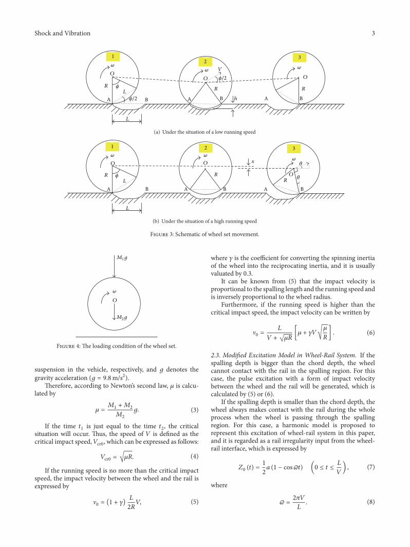
2.2. Traditional Excitation Model in Wheel-Rail System.According to the traditional model [20], there are twosituations of the wheel set movement on the spalling region,as shown in Figure 3, where𝜔 is the spinning angular velocity.When the wheel set runs with a low speed and reaches themarginal point A of the spalling region, the wheel set willrotate around point A until it contacts anothermarginal pointB. Then, it will rotate round point B, which results in thedynamic impact on the rail. When the wheel set runs witha high-speed and reaches point A, the wheel set will losecontact with the rail and just go along a perfect parabola.Later, it will contact with point B, which causes the dynamicimpact on the rail.
Thus, it can be seen that there is a critical impact speed,which is used to determine the excitation model of the railspalling in wheel-rail system.
In Figure 3(a) of the second situation, when the rotationangle of wheel set is 𝜙/2, the critical point will appear.Therefore, the time 𝑡
1is calculated by
𝑡1=𝜙/2
𝜔=𝑅𝜙
2𝑉. (1)
The assumption is that ℎ is far lower than 𝑅. So, the time𝑡2when the wheel set falls off the rail with a depth of ℎ is
calculated by
𝑡2= √
2ℎ
𝜇, (2)
where 𝜇 is the impact acceleration of the wheel set.When thewheel set loses contact with the rail, the loading
condition is shown in Figure 4, where the symbols 𝑀1
and 𝑀2are the sprung and unsprung mass of the primary
Shock and Vibration 3
A B
R
O
L
L
A B
O
BA
O
R R
h
V
12
3
𝜔𝜔𝜔
𝜙/2
𝜙/2
𝜙
(a) Under the situation of a low running speed
A B
R
O
L
L
A B
O
BA
ORR
1 2 3
x𝜔𝜔
𝜔𝜃
𝜃𝜙
(b) Under the situation of a high running speed
Figure 3: Schematic of wheel set movement.
M1g
M2g
O
𝜔
Figure 4: The loading condition of the wheel set.
suspension in the vehicle, respectively, and 𝑔 denotes thegravity acceleration (𝑔 = 9.8m/s2).
Therefore, according to Newton’s second law, 𝜇 is calcu-lated by
𝜇 =𝑀1+𝑀2
𝑀2
𝑔. (3)
If the time 𝑡1is just equal to the time 𝑡
2, the critical
situation will occur. Thus, the speed of 𝑉 is defined as thecritical impact speed,𝑉cr0, which can be expressed as follows:
𝑉cr0 = √𝜇𝑅. (4)
If the running speed is no more than the critical impactspeed, the impact velocity between the wheel and the rail isexpressed by
V0= (1 + 𝛾)
𝐿
2𝑅𝑉, (5)
where 𝛾 is the coefficient for converting the spinning inertiaof the wheel into the reciprocating inertia, and it is usuallyvaluated by 0.3.
It can be known from (5) that the impact velocity isproportional to the spalling length and the running speed andis inversely proportional to the wheel radius.
Furthermore, if the running speed is higher than thecritical impact speed, the impact velocity can be written by
V0=
𝐿
𝑉 + √𝜇𝑅[𝜇 + 𝛾𝑉√
𝜇
𝑅] . (6)
2.3. Modified Excitation Model in Wheel-Rail System. If thespalling depth is bigger than the chord depth, the wheelcannot contact with the rail in the spalling region. For thiscase, the pulse excitation with a form of impact velocitybetween the wheel and the rail will be generated, which iscalculated by (5) or (6).
If the spalling depth is smaller than the chord depth, thewheel always makes contact with the rail during the wholeprocess when the wheel is passing through the spallingregion. For this case, a harmonic model is proposed torepresent this excitation of wheel-rail system in this paper,and it is regarded as a rail irregularity input from the wheel-rail interface, which is expressed by
𝑍0(𝑡) =
1
2𝑎 (1 − cos𝜛𝑡) (0 ≤ 𝑡 ≤
𝐿
𝑉) , (7)
where
𝜛 =2𝜋𝑉
𝐿. (8)

4 Shock and Vibration
0
1
2
3
4
5Sp
allin
g de
pth
(mm
)
Critical length (mm)0 20 40 60 80 100 120 140
R400
R430
R450
R480
Figure 5: Critical length versus spalling depth.
It is worth noting that it is in the critical state betweenthe pulse excitation and the harmonic excitation when thespalling depth is just equal to the chord depth. Thus, thisspalling length is defined as the critical length, 𝐿cr, in thispaper. According to the geometrical relationship shown inFigure 5, the critical length can be expressed by
𝐿cr = 2√2𝑅𝑎 − 𝑎2. (9)
Suppose that a series of wheel radiuses are set as400mm, 430mm, 450mm, and 480mm; then the relation-ship between the critical length and spalling depth can beobtained, as shown in Figure 5. It can be seen that, given aspalling depth, the larger the wheel radius is, the longer thecritical length will be.
Therefore, the excitation modes in wheel-rail system canbe judged by the ratio of the spalling length to its criticallength. If the ratio is smaller than one, the wheel-rail systemis under the pulse excitation with a form of impact velocity;otherwise, it is under the harmonic excitation.
3. Vehicle-Track Coupled Dynamic Model
The basic idea of the theory of vehicle-track coupled dynam-ics is that two independent subsystems, including a vehiclesubsystem and a track subsystem, are taken as a unifiedsystem with a wheel-rail contact relationship as the link [20,21]. It is usually used to investigate the dynamic behavior ofthe vehicle running on the elastic rail. Consequently, investi-gation on thewheel-rail dynamic interaction due to excitationof the rail spalling in high-speed railway is carried out on thebasis of this theory.
As for the high-speed railway, there are two types oftrack structure, including the ballast track and the slab track.
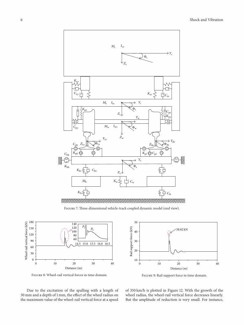
In general, the irregularity of the slab track is better than thatof the ballast track. Therefore, the ballast track is taken asan example in this paper. A vehicle-track coupled dynamicmodel [20] is adopted and shown in Figures 6 and 7, whosenotations are defined in Nomenclature for the Parameters.
The vehicle submodel consists of seven principal rigidcomponents, including one car body, two bogie frames, andfour wheel sets. The car body is supported on two double-axle bogies which are linked with the wheel sets throughthe primary suspensions and connected with the car bodythrough the secondary suspensions. The car body has thedegrees of freedom (DOFs) of the vertical, lateral, yaw, roll,and pitch motions, as well as each bogie frame and wheelset. Consequently, the total number of the DOFs is 35 for thevehicle submodel.
The track submodel is a so-called five-parameter model[21], which is based upon the hypothesis that load transmis-sion from a sleeper to the ballast approximately coincideswith cone distribution. Both the left and the right rails aretreated as continuous Bernoulli-Euler beams which are dis-cretely supported at rail-sleeper junctions by three layers ofsprings and dampers, representing the elasticity and dampingof the rail pad, ballast, and subgrade, respectively. The lengthof the beam is about 90 times that of the sleeper spacing,which can eliminate the boundary effect.
The wheel-rail coupled model is the essential elementthat couples the vehicle submodel with the track submodel atthe wheel-rail interfaces. A spatial wheel-rail coupling model[20] is adopted to simulate the complex geometry in thispaper. The nonlinear Hertzian elastic contact theory is usedto calculate the wheel-rail normal contact forces accordingto the elastic compression deformations of wheels and railsat contact points in the normal directions. The tangentialwheel-rail creep forces are calculated first by use of Kalker’slinear creep theory and then modified by Shen-Hedrick-Elkins nonlinear model. It is worth pointing out that thespalling defect is modeled as the external excitation in wheel-rail system.
4. Wheel-Rail DynamicInteraction due to Pulse Excitation
In order to investigate the wheel-rail dynamic interaction dueto the pulse excitation in this section, the spalling lengthshould be smaller than its critical length. For a new type ofwheel with the radius of 430mm in a high-speed vehicle, thecritical length is 58.62mm according to (9) by assuming thedepth of the rail spalling to be 1mm. Moreover, the spallinglength is kept as a constant, for example, 30mm assumedhere.
4.1. Characteristics ofWheel-Rail Vibration. When the vehiclepasses through the spalling region at a speed of 350 km/h,the calculated wheel-rail vertical dynamic force is shownin Figure 8. It can be seen that an enormous wheel-raildynamic force is produced, including a first peak of impactforce (named 𝑃
1force) and a second peak of impact force
(named 𝑃2forces), and the maximum value is 136.05 kN. It is

Shock and Vibration 5
Mc Icy 𝛽c
Csz Ksz
Mt Ity 𝛽t2
Cpz
Zt2Kpz
Zw4 Zw3
Z04 Z03
Zw2
Z02 Z01
P4 P3 mr EI
Kpv Cpv
P2 P1
Ms
Kpv
Mb
Kfv Cfv
Kw
Cw
Zs
Zb
V
Zc
𝛽t1
Zt1
Zw1
Zr
Cbv
−∞ +∞
Figure 6: Three-dimensional vehicle-track coupled dynamic model (elevation).
noticeable that 𝑃1force is mainly dominated by the high-
frequency interactions, while𝑃2force is done by themedium-
frequency interactions.Figure 9 displays the simulated response of the rail
support force delivered to the rail bottom through the railfastening and the rail pad. Under the excitation of the railspalling, the maximum value of the rail support force is38.82 kN.
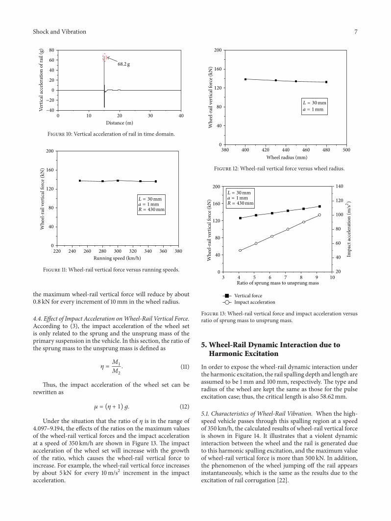
Thevertical acceleration response of the rail by simulationis represented in Figure 10. It indicates that the maximumvalue of the rail acceleration is about 68.2 g.
4.2. Effect of Running Speed on Wheel-Rail Vertical Force.The maximum values of the wheel-rail force with the speedranging from 250 km/h to 350 km/h are shown in Figure 11.It can be observed that there is little influence of therunning speed on themaximumwheel-rail vertical force. Forexample, the maximum value of the wheel-rail vertical forceis 137.35 kN at the speed of 250 km/h, while it is 136.05 kN atthe speed of 350 km/h.
What is noteworthy is that the running speed is in thescope of 250–350 km/h, which ismuch larger than the criticalimpact speed, 𝑉cr0, and it seems to be infinite. Under thissituation, the impact velocity obtained by (6) can be rewrittenas
V0= lim𝑉→∞
V0= 𝛾𝐿√
𝜇
𝑅. (10)
As a consequence, the impact velocity will decreaseslightly and is finally kept as a constant with the growth of therunning speed. It is the main reason why the running speedhas little effect on the wheel-rail vertical force.
4.3. Effect of Wheel Radius on Wheel-Rail Vertical Force. Forthe sake of investigating the effect of the wheel radius on thewheel-rail dynamic performance in this section, a set of wheelradiuses are assumed as 400mm, 430mm, 450mm, and480mm. Thus, the corresponding critical lengths of the railspalling are 56.53mm, 58.62mm, 59.97mm, and 61.94mm,respectively.
6 Shock and Vibration
Mc Icx
Zc
ΦcYc
Ksy
Csy
Kpz
Mt Itx
Ksz Csz
Φt
Yw
CpzKpy
Φw
YLrZw
Cph ZLr ΦLr
Cbh
Kbv Cbv
Mb
Kfv
Kw
Zs
Cw
Cfv
Φs
ΦRr
Yt
Zt
Cpy Mw Iwx
ZRr
YRr
Kph
Kbh
Kpv Cpv
Ys
Figure 7: Three-dimensional vehicle-track coupled dynamic model (end view).
0 10 20 30 400
30
60
90
120
150
180
14.5 15.0 15.5 16.0 16.56080
100120140
Whe
el-r
ail v
ertic
al fo
rce (
kN)
Distance (m)
P1P2
Figure 8: Wheel-rail vertical forces in time domain.
Due to the excitation of the spalling with a length of30mm and a depth of 1mm, the effect of the wheel radius onthe maximum value of the wheel-rail vertical force at a speed
0 10 20 30 4010
20
30
40
50
Rail
supp
ort f
orce
(kN
)
Distance (m)
38.82 kN
Figure 9: Rail support force in time domain.
of 350 km/h is plotted in Figure 12. With the growth of thewheel radius, the wheel-rail vertical force decreases linearly.But the amplitude of reduction is very small. For instance,
Shock and Vibration 7
0 10 20 30 40−40
−20
0
20
40
60
80
Vert
ical
acce
lera
tion
of ra
il (g
)
Distance (m)
68.2 g
Figure 10: Vertical acceleration of rail in time domain.
220 240 260 280 300 320 340 360 3800
40
80
120
160
200
Whe
el-r
ail v
ertic
al fo
rce (
kN)
Running speed (km/h)
L = 30mma = 1mmR = 430mm
Figure 11: Wheel-rail vertical force versus running speeds.
the maximum wheel-rail vertical force will reduce by about0.8 kN for every increment of 10mm in the wheel radius.
4.4. Effect of Impact Acceleration onWheel-Rail Vertical Force.According to (3), the impact acceleration of the wheel setis only related to the sprung and the unsprung mass of theprimary suspension in the vehicle. In this section, the ratio ofthe sprung mass to the unsprung mass is defined as
𝜂 =𝑀1
𝑀2
. (11)
Thus, the impact acceleration of the wheel set can berewritten as
𝜇 = (𝜂 + 1) 𝑔. (12)
Under the situation that the ratio of 𝜂 is in the range of4.097–9.194, the effects of the ratios on the maximum valuesof the wheel-rail vertical forces and the impact accelerationat a speed of 350 km/h are shown in Figure 13. The impactacceleration of the wheel set will increase with the growthof the ratio, which causes the wheel-rail vertical force toincrease. For example, the wheel-rail vertical force increasesby about 5 kN for every 10m/s2 increment in the impactacceleration.
380 400 420 440 460 480 5000
40
80
120
160
200
Whe
el-r
ail v
ertic
al fo
rce (
kN)
Wheel radius (mm)
L = 30mma = 1mm
Figure 12: Wheel-rail vertical force versus wheel radius.
3 4 5 6 7 8 9 100
40
80
120
160
200
Vertical force
Whe
el-r
ail v
ertic
al fo
rce (
kN)
Ratio of sprung mass to unsprung mass
20
40
60
80
100
120
140
Impact acceleration
L = 30mma = 1mmR = 430mm
Impa
ct ac
cele
ratio
n (m
/s2)
Figure 13: Wheel-rail vertical force and impact acceleration versusratio of sprung mass to unsprung mass.
5. Wheel-Rail Dynamic Interaction due toHarmonic Excitation
In order to expose the wheel-rail dynamic interaction underthe harmonic excitation, the rail spalling depth and length areassumed to be 1mm and 100mm, respectively. The type andradius of the wheel are kept the same as those for the pulseexcitation case; thus, the critical length is also 58.62mm.
5.1. Characteristics of Wheel-Rail Vibration. When the high-speed vehicle passes through this spalling region at a speedof 350 km/h, the calculated results of wheel-rail vertical forceis shown in Figure 14. It illustrates that a violent dynamicinteraction between the wheel and the rail is generated dueto this harmonic spalling excitation, and the maximum valueof wheel-rail vertical force is more than 500 kN. In addition,the phenomenon of the wheel jumping off the rail appearsinstantaneously, which is the same as the results due to theexcitation of rail corrugation [22].

8 Shock and Vibration
14.0 14.5 15.0 15.5 16.0
0
100
200
300
400
500
600
Whe
el-r
ail v
ertic
al fo
rce (
kN)
Distance (m)
Wheel jumping off rail
505kN
Figure 14: Wheel-rail vertical force in time domain.
14.0 14.5 15.0 15.5 16.0−400
−200
0
200
400
600
800
Vert
ical
acce
lera
tion
of ra
il (g
)
Distance (m)
707 g
Figure 15: Vertical acceleration of rail in time domain.
Once the wheel loses contact with the rail instantaneouslyand then falls down and contacts with the rail again, anenormous impact force between the wheel and the rail willbe produced, which can cause severe vibration to the rail.Figure 15 depicts the acceleration responses of the rail underthis condition by simulation. It can be seen that themaximumvalue of the rail acceleration is about 700 g.
5.2. Effect of Running Speed on Wheel-Rail Vertical Force.Under the condition that the speed is ranging from 250 km/hto 350 km/h, themaximumvalues of wheel-rail vertical forcesby simulation are shown in Figure 16. It can be found thatthe wheel-rail vertical force decreases with the increase ofthe speed, and the wheel-rail vertical forces are larger than500 kN. For example, the maximum value of the wheel-rail force is 644.1 kN at the speed of 250 km/h, while itbecomes 505 kN at the speed of 350 km/h. Its reason lies in therelationship between the main frequencies of the wheel-railvertical force and the excitation frequency. If the excitationfrequency comes near to the main frequency, the value of thewheel-rail vertical force will become much greater [22]. Themain frequency for the wheel-rail system employed in thispaper is in the vicinity of 700Hz. To be more exact, whenthe speed is 250 km/h and the spalling length is 100mm, theexcitation frequency is 694.4Hz, while it is 972.2Hz at thespeed of 350 km/h. As a result, the excitation frequency at thespeed of 250 km/h is closer to the main frequency than thatat the speed of 350 km/h.
220 240 260 280 300 320 340 360 3800
100
200
300
400
500
600
700
800
Whe
el-r
ail v
ertic
al fo
rce (
kN)
Running speed (km/h)
L = 100mma = 1mmR = 430mm
Figure 16: Wheel-rail vertical force versus running speeds.
6. The Safety Threshold ofRail Spalling Length
6.1. The Control Principle for Rail Spalling. The results men-tioned above show that the wheel-rail dynamic interactionunder the harmonic excitation is more serious than thatunder the pulse excitation for the rail spalling with the samedepth. For example, the maximum value of the wheel-railvertical force excited by the harmonic excitation is four timeslarger than that by the pulse excitation, and it is ten timesthat for the rail acceleration. That is to say, if the excitationmode is in the form of the harmonic irregularity, a violentwheel-rail dynamic interaction would be generated, while itwould become less mild for the excitation with the shape ofa pulse. However, the excitation mode in wheel-rail systemis determined by the matching relationship between thespalling length and its critical length.
It is a key point to control the rail spalling length whichshould be less than its critical length for any spalling depth.Thus, the excitation mode in wheel-rail system caused by therail spalling is in the shape of the pulse instead of the har-monic mode. So, according to this principle, the maximumof the rail spalling length is investigated in this section.
It is worth pointing out that effects of the running speedand the wheel radius on the wheel-rail dynamic interactioncan be neglected under the situation that the spalling lengthis less than its critical length (shown in Figures 11 and 12).Consequently, a running speed of 350 km/h and the wheelradius of 430mm are employed for the case study in thissection. In addition, the wheel-rail vertical force is takenas the most important safety index, whose limited value is170 kN by the relevant evaluation specification [23].
6.2. Effect of Rail Spalling Length onWheel-Rail Vertical Force.The spalling depth is usually more than 1mm on the railsurface, which is mainly focused on here. So, the correspond-ing critical length is more than 58mm for this type of therail spalling. According to the control principle mentionedabove, the rail spalling length should be less than 58mm.

Shock and Vibration 9
Table 1: Threshold value of the spalling length with different impact acceleration.
Impact acceleration (m/s2) 50 60 70 80 90 100Threshold value of the spalling length (mm) 50.36 45.85 42.20 39.25 37.09 35.11
0 10 20 30 40 50 60 7040
60
80
100
120
140
160
180
200
220
Threshold value of lengthWhe
el-r
ail v
ertic
al fo
rce (
kN)
Rail spalling length (mm)
Limited value
𝜇 = 66.22m/s2
𝜂 = 5.75
Figure 17: Influence of spalling length on the wheel-rail verticalforce.
Thus, a series of spalling lengths are assumedwithin the rangefrom 10mm to 60mmwith an interval of 10mm.The criticallength of 58mm is also included.
Figure 17 depicts influence of the spalling length on themaximumvalue of the wheel-rail vertical force by simulation,where the impact acceleration of the wheel set is 66.22m/s2and the ratio of the sprung mass to the unsprung mass is5.75. It can be seen that the wheel-rail vertical force increasesalmost linearly with the growth of the rail spalling length.Themaximum value of the wheel-rail vertical force is up to thelimited value, namely, 170 kN, when the rail spalling lengthincreases to 43.8mm. It means that the threshold value of therail spalling length is 43.8mm under these conditions.
6.3. Effect ofWheel Set Impact Acceleration onThreshold Valueof Spalling Length. The sprung and the unsprung mass aredifferent for different types of high-speed vehicles, resultingin the various wheel set impact acceleration of the railspalling. It also can be known from Figure 13 that the largerthe wheel set impact acceleration is, the greater the wheel-rail dynamic interaction will be. Therefore, the wheel setimpact acceleration might have significant influence on thesafety threshold of the rail spalling length. In this subsection,the threshold values of the rail spalling length are calculatedunder the conditions of different impact acceleration.
For the investigation, the impact acceleration of the wheelset is designated within the scope of 50–100m/s2, where thelimit conditions are taken into account. Accordingly, the ratioof the sprung mass to the unsprung mass varies from 4.1 to9.19.The threshold values of the spalling length with differentimpact acceleration are given in Table 1. It can be seen thatthe larger the impact acceleration is, the smaller the threshold
value of the spalling lengthwill be. For example, the thresholdvalue of the spalling length is 45.85mm when the impactacceleration is 60m/s2, while it is only 35.11mm when theimpact acceleration is 100m/s2.
The analysismentioned above indicates that, for the high-speed railway with the speed of 350 km/h, the maximumvalue of the rail spalling length is 35.11mm under the condi-tion that the spalling depth is 1mm or more. By consideringthe convenience of practical application, it is recommendedthat the maximum value of the rail spalling length should be35mm.
7. Conclusions
Based on the theory of vehicle-track coupled dynamics,wheel-rail dynamic vibration excited by the rail spalling inhigh-speed railway is analyzed.The following conclusions canbe obtained:
(1) Two kinds of excitation modes in wheel-rail system,including the pulse excitation and the harmonicexcitation, are generated due to the rail spalling. Theexcitation mode can be judged by the ratio of thespalling length to its critical length. If the ratio is lowerthan one, it is the pulse excitation; otherwise, it is theharmonic excitation.
(2) When a high-speed vehicle passes through the areawith a rail spalling forming the pulse excitation,an enormous wheel-rail impact force is generatedwith a first peak and a second peak. The analyzedresults indicate that the running speed and the wheelradius have little effect on the wheel-rail force, whilethe wheel set impact acceleration has an obviouseffect on the wheel-rail force. On the other hand, aviolent impact between the wheel and the rail willbe produced for the harmonic excitation mode, andthe phenomenon that the wheel jumps off the railinstantaneously appears repeatedly. In addition, therunning speed has an obvious effect on the wheel-railforce.
(3) It is very important to control the spalling lengthfirstly for investigating the safety threshold of therail spalling. The control principle is that the spallinglength should be less than its critical length for anyspalling depth, so as to make the wheel-rail systemunder the pulse excitation instead of the harmonicexcitation.
(4) Under the situation of the pulse excitation with thedepth being 1mm or more, the wheel-rail verticalforce increases linearly with the growth of the spallinglength. If the length of the rail spalling is no larger

10 Shock and Vibration
than 35mm, the vehicle at the speed of 350 km/h willbe in a safe condition.
In practice, there are usually multiple spallings existingon the rail surface. Investigations on the dynamic excitationsfrom multiple spallings will be studied in our future workeven if they are beyond the scope of this paper.
Nomenclature for the Parameters
𝑀c: Mass of a car body𝑀t: Mass of a bogie𝑀w: Mass of a wheel set𝑀r: Mass of a rail per meter𝑀s: Mass of a sleeper𝑀b: Mass of a ballast𝐼cy, 𝐼cx: Pitch and roll moment of inertia of a car body,
respectively𝐼ty, 𝐼tx: Pitch and roll moment of inertia of a bogie,
respectively𝐼wx: Roll moment of inertia of a wheel set𝐸𝐼: Bending stiffness of a rail𝐾sz, 𝐾sy: Vertical and lateral stiffness of the secondary
suspension, respectively𝐶sz, 𝐶sy: Vertical and lateral damping of the secondary
suspension, respectively𝐾pz, 𝐾py: Vertical and lateral stiffness of the primary
suspension, respectively𝐶pz, 𝐶py: Vertical and lateral damping of the primary
suspension, respectively𝐾pv, 𝐾ph: Vertical and lateral stiffness between rail and
sleeper, respectively𝐶pv, 𝐶ph: Vertical and lateral damping between rail and
sleeper, respectively𝐾bv: Vertical stiffness between sleeper and ballast𝐶bv: Vertical damping between sleeper and ballast𝐾fv: Vertical stiffness between ballast and subgrade𝐶fv: Vertical damping between ballast and subgrade𝐾w: Shear stiffness between front and back ballast𝐶w: Shear damping between front and back ballast𝛽c, Φc: Pitch and roll motion of a car body, respectively𝛽ti, Φti: Pitch and roll motion of a bogie (𝑖 = 1, 2),
respectively𝛽wi, Φwi: Pitch and roll motion of a wheel set (𝑖 = 1 ∼ 4),
respectively𝑍c, 𝑌c: Vertical and lateral motion of a car body,
respectively𝑍ti, 𝑌ti: Vertical and lateral motion of a bogie (𝑖 = 1, 2),
respectively𝑍wi, 𝑌wi: Vertical and lateral motion of a wheel set
(𝑖 = 1 ∼ 4), respectively𝑍r: Vertical motion of a rail𝑌Lr, 𝑌Rr: Lateral motion of left and right rail, respectively𝑍s, 𝑌s: Vertical and lateral motion of a sleeper,
respectively𝑍b: Vertical motion of a ballast𝑍0𝑖: Irregularity in wheel-rail system (𝑖 = 1 ∼ 4)
𝑃𝑖: Wheel-rail vertical force (𝑖 = 1 ∼ 4).
Competing Interests
The authors declare that they have no competing interests.
Acknowledgments
This work was supported by the National Basic ResearchProgram of China (973 Program) under Grants no.2013CB036206 and no. 2013CB036205.
References
[1] D. F. Cannon and H. Pradier, “Rail rolling contact fatigueresearch by the EuropeanRail Research Institute,”Wear, vol. 191,no. 1-2, pp. 1–13, 1996.
[2] J. Sun, K. J. Sawly, D. H. Stone, and D. F. Teter, “Progressin the reducing of wheel spalling,” in Proceedings of the 12thInternational Congress on Wheelset, pp. 18–29, Qingdao, China,September 1998.
[3] Y. Sato and A.Matsumoto, “Review on rail corrugation studies,”in Proceeding of the 5th International Congress on ContactMechanics and Wear of Wheel/Rail System, Japan, pp. 74–80,Tokyo, Japan, July 2000.
[4] Y. R. Jiang and H. Sehitoglu, “Fatigue and stress analysis ofrolling contact,” Tech. Rep. 161, UILU-ENG 923602, Universityof Illinois at Champaign, 1992.
[5] J. J. Kalker,Three-Dimensional Elastic Bodies on Rolling Contact,Kluwer Academic, Dordrecht, The Netherlands, 1990.
[6] K. L. Knothe, A.Theiler, and S. Guney, “Investigation of contactstress on the wheel/rail-system at steady state curving,” VehicleSystem Dynamics, vol. 33, pp. 616–628, 2000.
[7] J. C. Simo and T. A. Laursen, “An augmented lagrangiantreatment of contact problems involving friction,” Computersand Structures, vol. 42, no. 1, pp. 97–116, 1992.
[8] P. Wriggers and G. Zavarise, “Application of augmentedLagrangian techniques for non-linear constitutive laws incontact interfaces,” Communications in Numerical Methods inEngineering, vol. 9, no. 10, pp. 815–824, 1993.
[9] P. Alart and A. Curnier, “A mixed formulation for frictionalcontact problems prone to Newton like solution methods,”Computer Methods in Applied Mechanics and Engineering, vol.92, no. 3, pp. 353–375, 1991.
[10] M. Olzak, J. Stupnicki, and R. Wojcik, “Investigation of crackpropagation during contact by a finite element method,”Wear,vol. 146, no. 2, pp. 229–240, 1991.
[11] M. Olzak, J. Stupnicki, and R. Wojcik, “Numerical analysis of3D cracks propagating in the rail-wheel contact zone,” in RailQuality and Maintenance for Modern Railway Operation, J. J.Kalker, D. F. Cannon, and O. Orringer, Eds., pp. 385–395, 1993.
[12] S. Bogdanski, M. Olzak, and J. Stupnicki, “Numerical stressanalysis of rail rolling contact fatigue cracks,”Wear, vol. 191, no.1-2, pp. 14–24, 1996.
[13] R. Smallwood, J. C. Sinclair, and K. J. Sawley, “An optimizationtechnique to minimize rail contact stresses,”Wear, vol. 144, no.1-2, pp. 373–384, 1991.
[14] K. Hou, J. Kalousek, H. Lamba et al., “Thermal effect onadhesion in wheel/rail,” in Proceedings of the 5th InternationalCongress on Contact Mechanics and Wear of Wheel/Rail System,pp. 239–244, Tokyo, Japan, July 2000.

Shock and Vibration 11
[15] K. Knothe and S. Liebelt, “Determination of temperatures forsliding contact with applications for wheel-rail systems,”Wear,vol. 189, no. 1-2, pp. 91–99, 1995.
[16] M. Ishida and N. Abe, “Experimental study on rolling contactfatigue from the aspect of residual stress,”Wear, vol. 191, no. 1-2,pp. 65–71, 1996.
[17] J. Eisenmann and G. Leykauf, “The effect of head checking onthe bending fatigue strength of railway rails,” in Proceedings ofthe International Conference on Rail Quality and Maintenancefor Modern Railway Operation, pp. 373–384, Delft, The Nether-lands, June 1992.
[18] J. Piotrowski, “Contact loading of a high rail in curves phys-ical simulation method to investigate shelling,” Vehicle SystemDynamics, vol. 17, no. 1-2, pp. 57–79, 1988.
[19] H. Yokoyama, S. Mitao, S. Yamamoto et al., “Effect of the angleof attack on flaking behavior in pearlitic and bainitics steel,”in Proceedings of the 5th International Congress on ContactMechanics and Wear of Wheel/Rail System, pp. 154–160, Tokyo,Japan, July 2000.
[20] W. Zhai, K. Wang, and C. Cai, “Fundamentals of vehicle-trackcoupled dynamics,” Vehicle System Dynamics, vol. 47, no. 11, pp.1349–1376, 2009.
[21] W. Zhai and X. Sun, “A detailed model for investigating verticalinteraction between railway vehicle and track,” Vehicle SystemDynamics, vol. 23, supplement1, pp. 603–615, 1994.
[22] K. Y.Wang, P. F. Liu,W.M. Zhai, C.Huang, Z.G. Chen, and J.M.Gao, “Wheel/rail dynamic interaction due to excitation of railcorrugation in high-speed railway,” Science China TechnologicalSciences, vol. 58, no. 2, pp. 226–235, 2014.
[23] UIC CODE-518, “Testing and approval of railway vehiclesfrom the point of view of their dynamic behaviour-safety-trackfatigue-running behaviour,” 2009.

International Journal of
AerospaceEngineeringHindawi Publishing Corporationhttp://www.hindawi.com Volume 2014
RoboticsJournal of
Hindawi Publishing Corporationhttp://www.hindawi.com Volume 2014
Hindawi Publishing Corporationhttp://www.hindawi.com Volume 2014
Active and Passive Electronic Components
Control Scienceand Engineering
Journal of
Hindawi Publishing Corporationhttp://www.hindawi.com Volume 2014
International Journal of
RotatingMachinery
Hindawi Publishing Corporationhttp://www.hindawi.com Volume 2014
Hindawi Publishing Corporation http://www.hindawi.com
Journal ofEngineeringVolume 2014
Submit your manuscripts athttp://www.hindawi.com
VLSI Design
Hindawi Publishing Corporationhttp://www.hindawi.com Volume 2014
Hindawi Publishing Corporationhttp://www.hindawi.com Volume 2014
Shock and Vibration
Hindawi Publishing Corporationhttp://www.hindawi.com Volume 2014
Civil EngineeringAdvances in
Acoustics and VibrationAdvances in
Hindawi Publishing Corporationhttp://www.hindawi.com Volume 2014
Hindawi Publishing Corporationhttp://www.hindawi.com Volume 2014
Electrical and Computer Engineering
Journal of
Advances inOptoElectronics
Hindawi Publishing Corporation http://www.hindawi.com
Volume 2014
The Scientific World JournalHindawi Publishing Corporation http://www.hindawi.com Volume 2014
SensorsJournal of
Hindawi Publishing Corporationhttp://www.hindawi.com Volume 2014
Modelling & Simulation in EngineeringHindawi Publishing Corporation http://www.hindawi.com Volume 2014
Hindawi Publishing Corporationhttp://www.hindawi.com Volume 2014
Chemical EngineeringInternational Journal of Antennas and
Propagation
International Journal of
Hindawi Publishing Corporationhttp://www.hindawi.com Volume 2014
Hindawi Publishing Corporationhttp://www.hindawi.com Volume 2014
Navigation and Observation
International Journal of
Hindawi Publishing Corporationhttp://www.hindawi.com Volume 2014
DistributedSensor Networks
International Journal of