research article hysteresis control for shunt active power...
TRANSCRIPT

Research ArticleHysteresis Control for Shunt Active Power Filter underUnbalanced Three-Phase Load Conditions
Z. Chelli,1,2 R. Toufouti,1 A. Omeiri,2 and S. Saad3
1Department of Electrical Engineering, University of Mohamed-Cherif Messaadia of Souk Ahras, P.O. Box 1553,41000 Souk Ahras, Algeria2Department of Electrical Engineering, University of Badji Mokhtar of Annaba, P.O. Box 12, 23000 Annaba, Algeria3Department of Electromechanical Engineering, University of Badji Mokhtar of Annaba, P.O. Box 12, 23000 Annaba, Algeria
Correspondence should be addressed to Z. Chelli; [email protected]
Received 8 November 2014; Accepted 10 March 2015
Academic Editor: Muhammad Taher Abuelma’atti
Copyright © 2015 Z. Chelli et al.This is an open access article distributed under the Creative Commons Attribution License, whichpermits unrestricted use, distribution, and reproduction in any medium, provided the original work is properly cited.
This paper focuses on a four-wire shunt active power filter (APF) control scheme proposed to improve the performance of the APF.This filter is used to compensate harmonic distortion in three-phase four-wire systems. Several harmonic suppression techniqueshave been widely proposed and applied to minimize harmonic effects. The proposed control scheme can compensate harmonicsand reactive power of the nonlinear loads simultaneously. This approach is compared to the conventional shunt APF referencecompensation strategy.Thedeveloped algorithm is validated by simulation tests usingMATLABSimulink.Theobtained results havedemonstrated the effectiveness of the proposed scheme and confirmed the theoretical developments for balanced and unbalancednonlinear loads.
1. Introduction
Power electronic equipments are largely used in modernelectrical systems leading to an increase of the harmonicspollution in the AC main supplies. Thus, harmonic currentsgenerated by static converter mainly rectifiers have becomea great issue in the field of electrical engineering due to theadverse effects on all electrical equipments [1]. The intensiveuse of nonlinear equipments has increased the demand forharmonics suppression and reactive power compensation. Ithas been proved by many reported work that these nonlinearloads are the main cause of poor power factor and highharmonic distortion [2].
The presence of harmonics in the power system resultsin numerous drawbacks such as high power loss in distri-bution network, electromagnetic interference in communi-cation systems, and failures of power protection devices andelectrical and electronic equipments. These drawbacks cangreatly affect the industrial process and commercial activitiesbecause they can lead to a decrease in the productivity andcan also affect the quality of the products [3]. The harmonicsgenerated by these nonlinear load cause voltage distortion
affecting other loads connected at the same point of commoncoupling.
The APF was deeply studied and applied as an efficientsolution to the problem of harmonics pollution and theireffects [4].This type of filters is proved as an appropriate tech-nique to suppress harmonic voltage and current disturbances[5, 6].
The APF injects harmonic current (for shunt activefilter) or voltage (for serie active filter) into the powersource but in opposite direction. Different harmonic currentidentification and extraction techniques were studied andused [7–10] such as synchronous reference (d-q-0) theory,instantaneous real-reactive power (p-q) theory, modifiedinstantaneous p-q theory, flux-based controller, notch filter,and neural network techniques [10]. Though p-q theory hasgood transient response time and steady-state accuracy [6],it is found to be not suitable for estimating reference currentunder nonideal source voltage conditions [6, 11]. This paperpresents an analysis and simulation of shunt active filterunder unbalanced nonlinear load. In order to identify shuntAPF reference current a novel p-q theory is used based onPLL for unbalanced main voltages to control shunt APF.
Hindawi Publishing CorporationJournal of Electrical and Computer EngineeringVolume 2015, Article ID 391040, 9 pageshttp://dx.doi.org/10.1155/2015/391040
2 Journal of Electrical and Computer Engineering
Sourceis il Ls
Pcc
ifa
Active power filter
Vdc/2
dc/2V
Unbalancednonlinear
loads
Lf
Figure 1: Shunt active filter under unbalanced nonlinear load.
Hysteresis controllers are employed to generate switchingsignals of the voltage source inverter. The proposed activefilter can compensate both harmonic currents and reactivepower (correcting power factor to the unity) simultaneously.To validate and confirm the developed algorithms for theproposed scheme, simulation tests are conducted to show theeffectiveness of this approach.
2. Shunt Active Filter Basic Principle
The shunt active power filter operating principle is to injectinto the power supply network the same harmonics currentas that generated by the nonlinear load but in the oppositedirection. Figure 1 illustrates a typical structure of the shuntAPF connected to a main source [12].
Supposing that linear and nonlinear loads are connectedat common coupling point (CCP) [11], under this conditionthe supply current (𝑖
𝑠) flowing through the transmission line
will be the load current (𝑖𝑙) which is nonsinusoidal. The
designed active power filter is a three-phase PWM (pulsewith modulation) voltage source inverter (VSI), connected inparallel with the AC source through the common couplingpoint of (CCP) [12]; the current source equation can beexpressed as
𝑖𝑠= 𝑖𝑙− 𝑖𝑓. (1)
The performance of active power filter depends mainlyon the technique used to identify and extract the referencecurrent (harmonic current) and the inverter control strategy[9, 13]. This inverter uses DC voltage capacitor as a supplyand can be switched at high frequency to generate the currentthat will eliminate the harmonic current from the mainsource. The current waveform used to suppress harmonicsis obtained by VSI in the current controlled mode and theinterface filter [14].
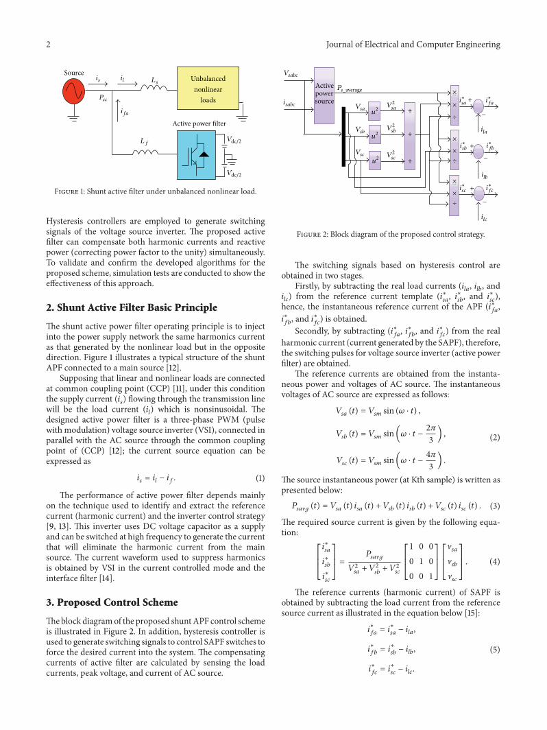
3. Proposed Control Scheme
Theblock diagramof the proposed shuntAPF control schemeis illustrated in Figure 2. In addition, hysteresis controller isused to generate switching signals to control SAPF switches toforce the desired current into the system. The compensatingcurrents of active filter are calculated by sensing the loadcurrents, peak voltage, and current of AC source.
Activepowersource
Vsabc
isabc
Ps_average ×
×
×
×
×
...
Vsa
Vsb
Vsc
u2
u2
u2
V2sa
V2sb
V2sc
+
+
+
+
÷
÷
÷
×...
−
+
−
+
−
i∗sa i
∗fa
ila
i∗sb i
∗fb
ilb
i∗sc i
∗fc
ilc
Figure 2: Block diagram of the proposed control strategy.
The switching signals based on hysteresis control areobtained in two stages.
Firstly, by subtracting the real load currents (𝑖𝑙𝑎, 𝑖𝑙𝑏, and
𝑖𝑙𝑐) from the reference current template (𝑖∗
𝑠𝑎, 𝑖∗𝑠𝑏, and 𝑖∗
𝑠𝑐),
hence, the instantaneous reference current of the APF (𝑖∗𝑓𝑎,
𝑖∗
𝑓𝑏, and 𝑖∗
𝑓𝑐) is obtained.
Secondly, by subtracting (𝑖∗𝑓𝑎, 𝑖∗𝑓𝑏, and 𝑖∗
𝑓𝑐) from the real
harmonic current (current generated by the SAPF), therefore,the switching pulses for voltage source inverter (active powerfilter) are obtained.
The reference currents are obtained from the instanta-neous power and voltages of AC source. The instantaneousvoltages of AC source are expressed as follows:
𝑉𝑠𝑎(𝑡) = 𝑉
𝑠𝑚sin (𝜔 ⋅ 𝑡) ,
𝑉𝑠𝑏(𝑡) = 𝑉
𝑠𝑚sin(𝜔 ⋅ 𝑡 − 2𝜋
3) ,
𝑉𝑠𝑐(𝑡) = 𝑉
𝑠𝑚sin(𝜔 ⋅ 𝑡 − 4𝜋
3) .
(2)
The source instantaneous power (at Kth sample) is written aspresented below:
𝑃𝑠𝑎V𝑔 (𝑡) = 𝑉𝑠𝑎 (𝑡) 𝑖𝑠𝑎 (𝑡) + 𝑉𝑠𝑏 (𝑡) 𝑖𝑠𝑏 (𝑡) + 𝑉𝑠𝑐 (𝑡) 𝑖𝑠𝑐 (𝑡) . (3)
The required source current is given by the following equa-tion:
[[
[
𝑖∗
𝑠𝑎
𝑖∗
𝑠𝑏
𝑖∗
𝑠𝑐
]]
]
=
𝑃𝑠𝑎V𝑔
𝑉2𝑠𝑎+ 𝑉2
𝑠𝑏+ 𝑉2𝑠𝑐
[[
[
1 0 0
0 1 0
0 0 1
]]
]
[[
[
V𝑠𝑎
V𝑠𝑏
V𝑠𝑐
]]
]
. (4)
The reference currents (harmonic current) of SAPF isobtained by subtracting the load current from the referencesource current as illustrated in the equation below [15]:
𝑖∗
𝑓𝑎= 𝑖∗
𝑠𝑎− 𝑖𝑙𝑎,
𝑖∗
𝑓𝑏= 𝑖∗
𝑠𝑏− 𝑖𝑙𝑏,
𝑖∗
𝑓𝑐= 𝑖∗
𝑠𝑐− 𝑖𝑙𝑐.
(5)

Journal of Electrical and Computer Engineering 3
T
t1
BUpper
BLower
1/2Vdc
−1/
Upper band
Lower band
Actual current
Reference current
2Vdc
Figure 3: Diagram of hysteresis current control.
4. Modeling of Hysteresis Current Controller
Several harmonic current control strategies were proposedand used for shunt active filter control. Hysteresis currentcontrol strategy can be easily implemented in real-timeapplications [16]. The scheme of this control strategy used tocontrol the shunt active filter is shown in Figure 3 [15, 17].
This subsystem of hysteresis current controller was devel-oped to generate the switching pulses to control VSI switchesby comparing the real current to the reference current. Thecontrol scheme gives the switching pattern of active filterswitches in order to maintain the real injected current withina desired hysteresis band (HB) as illustrated in Figure 3 [15–18]. In the case of positive input current 𝑖
𝑓, the current error
exceeds the upper limit of the hysteresis band; thus inverteroutput should be set as zero, so current error will be forcedto the opposite direction without reaching the other outerlimit. If this zero condition does not provide the opposite ofcurrent error, it will keep forwarding through inner limit tothe other outer hysteresis limit. At this time, a reverse polarityof inverter output will be controlled and therefore currentdirection will be reversed [14, 15, 17].
The switching frequency of hysteresis current controlstrategy described and presented above depends mainly onhow fast the current changes from upper limit to lowerlimit of hysteresis band and inversely. Thus, the switchingfrequency does not remain constant throughout the switch-ing operation but changes along with the current waveform[15, 17, 18].
Figure 4 shows two-level hysteresis current controlmethod implementation using S-R flip-flop circuits for athree-phase inverter.
The comparator outputs go into flip-flop and the positiveinner band limit output goes to set input (S) while thenegative inner band limit output goes to reset input (R)of flip-flop. The output of the flip-flop is used to gate thetransistors; Q gates the upper transistor and Q bar gates thelower transistor [19, 20].
5. Simulation Results
MATLAB Simulink software is used to develop and simulatethe mathematical model in order to validate and confirm
Table 1: Model parameters for unbalanced load.
Loads 𝑅 (Ω) 𝐿 (mh) 𝐶 (F)Nonlinear load 150 100 0.01Unbalanced loadLoad 1 150 100 0Load 2 80 200 0Load 3 100 50 0
ea
BUpper
BUpper
BUpper
BLower
BLower
BLower
eb
ec
ea ≥ Bup
ea ≤ Bup
eb ≥ Bup
eb ≤ Bup
ec ≥ Bup
ec ≤ Bup
S1
R1
S1
R1
S1
R1
Q1
Q1
Q1
Q1
Q1
Q1
Sa
Sa
Sb
Sb
Sc
Sc
Comparator Flip-flops Bridgeswitches
Figure 4: Simplified model of a fixed hysteresis-band control.
the effectiveness and the feasibility of the proposed controlalgorithm for both balanced and unbalanced nonlinear loadconditions. The simulation of active filter operation withdifferent types of loads is conducted using a balanced andsinusoidal three-phase voltages system as shown in Figure 5.The parameters values used in the simulation tests arepresented below.
Three-phase source with line-to-line voltage is equal to380V and a frequency of 50Hz. The source impedancewith Rs = 0.001Ω and Ls = 0.25mH. The shunt APF isa three-phase MOSFET-based current controlled voltagesource inverter with an output AC filter (Lf = 35mH, Rf =3.5Ω) and two DC voltage ±2𝑉dc = ±650V.
The load is an uncontrolled three-phase bridge rectifierwith R-L-C load with three-phase unbalanced loads aspresented in Table 1.
Figures 5 and 6 have shown the voltage source, andthe obtained results have shown a high filtering quality ofharmonic currents. The different waveforms obtained by theproposed control method are illustrated in Figures 7–21.
From these waveforms, it can be noted that the behaviorof the active filter is analysed and studied in steady-stateoperation. Figures 16, 17, and 18 show load currents, activefilter compensation currents, and source currents for 3 phaseswith a neutral wire.TheTHDof the source current is the sameas that of the load current when the filter is not connected(12.55% for phase-a, 10.58% for phase-𝑏, and 10.53% forphase-c); these values are well above the IEEE 519 standards.In order to reduce the harmonic pollution within the IEEE

4 Journal of Electrical and Computer Engineering
0 0.01 0.02 0.03 0.04 0.05 0.06 0.07 0.08 0.09 0.1
Phase voltages of power system
Time (s)
250
200
150
100
50
0
−50
−100
−150
−200
−250
Vsabc
(V)
Figure 5: Power system phase voltages.
0 0.002 0.004 0.006 0.008 0.01 0.012 0.014 0.016 0.018 0.02
Phase voltages of power system
Time (s)
250
200
150
100
50
0
−50
−100
−150
−200
−250
Vsabc
(V)
Figure 6: Zoom of power system phase voltages.
0 0.01 0.02 0.03 0.04 0.05 0.06 0.07 0.08 0.09 0.1
Balanced nonlinear load currents waveforms
Time (s)
3
2
1
0
−1
−2
−3
i labc
(A)
Figure 7: Balanced nonlinear load currents waveforms.
0 0.01 0.02 0.03 0.04 0.05 0.06 0.07 0.08 0.09 0.1
Three phase unbalanced load currents waveforms
Time (s)
3
2
1
0
−1
−2
−3
i labc
(A)
Figure 8: Three-phase unbalanced nonlinear and neutral load cur-rents waveforms.
0 0.01 0.02 0.03 0.04 0.05 0.06 0.07 0.08 0.09 0.1
Load currents waveforms
Temps (s)
5
4
3
2
1
0
−1
−2
−3
−4
−5
i labc
(A)
Figure 9: Total load currents waveform.
519 standards, the proposed algorithm based on SAPF isintroduced and the real active filter current is illustrated inFigure 13. By injecting the required harmonic current to themain source, the source current becomes sinusoidal as shownin Figure 14. Connecting the active filter with the proposedcontrol algorithm, the THDof the source current is improvedto reach 1.69% in phase-a, 1.89% in phase-𝑏, and 1.85% inphase-c, which is within the IEEE 519 standards. However,with the use of conventional method pq, the THD of thesource current is still unsatisfactorywith the following values:6.84% in phase-a, 6.09% in phase-𝑏, and 5.56% in phase-𝑐.This indeed shows the potency of the proposed method toperformwell compared to conventional methods in reducingthe value of THD. The harmonic frequency spectrum of thecompensated source current is shown in Figures 19–21.
Table 2 outlines comparative results obtained using theproposed approach against conventional methods.
6. Conclusion
Thework presented in this paper has demonstrated and con-firmed the effectiveness of the proposed control method for

Journal of Electrical and Computer Engineering 5
0 2 4 6 8 10 12 14 16 180
102030405060708090
100110
Total harmonic spectrum of phase-a load current
Harmonic order20
Mag
nitu
de o
f fun
dam
enta
lIla
(%)
Figure 10: Frequency spectrum of phase-a load current.
0 2 4 6 8 10 12 14 16 18 200
102030405060708090
100110
Total harmonic spectrum of phase-b load current
Harmonic order
I la
(%)
Mag
nitu
de o
f fun
dam
enta
l
Figure 11: Frequency spectrum of phase-b load current.
Table 2: The comparative results of THD.
WithoutAPF
With conventionalmethod pq
With theproposedmethod
THDPhase-𝑎 12.55% 6.84% 1.69%Phase-𝑏 10.58% 6.09% 1.89%Phase-𝑐 10.53% 5.56% 1.85%
a shunt active filter application under unbalanced nonlinearloads. The tests carried out by computer simulation haveverified the efficiency of the proposed control scheme. Theobtained results prove that the purpose of proposed controlalgorithm has been successfully achieved under unbalancedor balanced load. The THD of the source current is reducedbelow 5% which is the limit imposed by the IEEE 519standards (1992) for both balanced and unbalanced loadsusing the APF. Furthermore, the proposed control strategy isvery simple and robust.
0 2 4 6 8 10 12 14 16 18 200
102030405060708090
100110
Total harmonic spectrum of phase-c load current
Harmonic order
I lc
(%)
Mag
nitu
de o
f fun
dam
enta
l
Figure 12: Frequency spectrum of phase-c load current.
0 0.01 0.02 0.03 0.04 0.05 0.06 0.07 0.08 0.09 0.1
Active filter compensation currents waveforms
Time (s)
4
3
2
1
0
−1
−2
−3
−4
i fabc
(A)
Figure 13: Active filter currents waveform with the proposed con-trol.
0 0.01 0.02 0.03 0.04 0.05 0.06 0.07 0.08 0.09 0.1
Source currents waveforms
Time (s)
4
3
2
1
0
−1
−2
−3
−4
i sabc
(A)
Figure 14: Source currents waveforms.

6 Journal of Electrical and Computer Engineering
0 0.002 0.004 0.006 0.008 0.01 0.012 0.014 0.016 0.018 0.02
Source currents waveforms
Time (s)
4
3
2
1
0
−1
−2
−3
−4
i sabc
(A)
Figure 15: Zoom of source currents waveform.
0 0.01 0.02 0.03 0.04 0.05 0.06 0.07 0.08 0.09 0.1
Source, load, and active filter currents waveforms
Time (s)
5
4
3
2
1
0
−1
−2
−3
−4
−5
i sai lai fa
(A)
(a) With conventional method pq
0 0.01 0.02 0.03 0.04 0.05 0.06 0.07 0.08 0.09 0.1
Source, load, and active filter currents waveforms
Time (s)
5
4
3
2
1
0
−1
−2
−3
−4
−5
i sai lai fa
(A)
(b) With the proposed control scheme
Figure 16: Source, load, and active filter currents of phase-a waveforms.
0 0.01 0.02 0.03 0.04 0.05 0.06 0.07 0.08 0.09 0.1
Source, load, and active filter currents waveforms
Time (s)
6
4
2
0
−2
−4
−6
i sbi lbi fb
(A)
(a) With conventional method pq
0 0.01 0.02 0.03 0.04 0.05 0.06 0.07 0.08 0.09 0.1
Source, load, and active filter currents waveforms
Temps (s)
5
4
3
2
1
0
−1
−2
−3
−4
−5
i sbi lbi fb
(A)
(b) With the proposed control scheme
Figure 17: Source, load, and active filter currents of phase-b waveforms.

Journal of Electrical and Computer Engineering 7
Source, load, and active filter currents waveforms6
4
2
0
−2
−4
−60 0.01 0.02 0.03 0.04 0.05 0.06 0.07 0.08 0.09 0.1
Time (s)
i sci lci fc
(A)
(a) With conventional method pq
5
4
3
2
1
0
−1
−2
−3
−4
0 0.01 0.02 0.03 0.04 0.05 0.06 0.07 0.08 0.09 0.1
Source, load, and active filter currents waveforms
Time (s)
−5
i sci lci fc
(A)
(b) With the proposed control scheme
Figure 18: Source, load, and active filter currents of phase-c waveforms.
0 2 4 6 8 10 12 14 16 18 200
102030405060708090
100110
Total harmonic spectrum of phase-a source current
Harmonic order
I sa
(%)
Mag
nitu
de o
f fun
dam
enta
l
(a) With conventional method pq
0 2 4 6 8 10 12 14 16 18 200
102030405060708090
100110
Total harmonic spectrum of phase-a load current
Harmonic order
I la
(%)
Mag
nitu
de o
f fun
dam
enta
l
(b) With the proposed control scheme
Figure 19: Frequency spectrum phase-a source current.
0 2 4 6 8 10 12 14 16 18 200
102030405060708090
100110
Total harmonic spectrum of phase-b source current
Harmonic order
I sb
(%)
Mag
nitu
de o
f fun
dam
enta
l
(a) With conventional method pq
0 2 4 6 8 10 12 14 16 18 200
102030405060708090
100110
Total harmonic spectrum of phase-b source current
Harmonic order
I sb
(%)
Mag
nitu
de o
f fun
dam
enta
l
(b) With the proposed control scheme
Figure 20: Frequency spectrum phase-b source current.

8 Journal of Electrical and Computer Engineering
0 2 4 6 8 10 12 14 16 18 200
102030405060708090
100110
Total harmonic spectrum of phase-c source current
Harmonic order
I sc
(%)
Mag
nitu
de o
f fun
dam
enta
l
(a) With conventional method pq
0 2 4 6 8 10 12 14 16 18 200
102030405060708090
100110
Total harmonic spectrum of phase-c source current
Harmonic order
I sc
(%)
Mag
nitu
de o
f fun
dam
enta
l
(b) With the proposed control scheme
Figure 21: Frequency spectrum of phase-c source current.
Conflict of Interests
The authors declare that there is no conflict of interestsregarding the publication of this paper.
Acknowledgments
The authors like to thank both theMIPS Laboratory (France)for the technical support and the Algerian General Agency ofResearch for its financial support.
References
[1] G. Adam, A. G. Stan, and G. Livint, “A Matlab-Simulinkapproach to shunt active power filters,” inProceedings of the 25thEuropean Conference on Modelling and Simulation (ECMS ’11),pp. 205–210, Krakow, Poland, June 2011.
[2] E. Ozdemi, K. Mura, and S. Ozdemir, “Active power filterfor power compensation under non-ideal mains voltages,” inProceedings of the 11thMediterranean Conference on Control andAutomation (MED ’03), 2003.
[3] J. L. Afonso, C. Couto, and J. S. Martins, “Active filters withcontrol based on the p-q theory,” IEEE Industrial ElectronicsSociety Newsletter, vol. 47, no. 3, pp. 5–10, 2000.
[4] M. I. M. Montero, E. R. Cadaval, and F. B. Gonzalez, “Com-parison of control strategies for shunt active power filters inthree-phase four-wire systems,” IEEE Transactions on PowerElectronics, vol. 22, no. 1, pp. 229–236, 2007.
[5] R. A. Hooshmand andM. Torabian Esfahani, “A new combinedmethod in active filter design for power quality improvementin power systems,” ISA Transactions, vol. 50, no. 2, pp. 150–158,2011.
[6] M. Ucar and E. Ozdemir, “Control of a 3-phase 4-leg activepower filter under non-ideal mains voltage condition,” ElectricPower Systems Research, vol. 78, no. 1, pp. 58–73, 2008.
[7] K. M. Mahajan, S. George, and S. Thale, “Simulation of shuntactive filter using D-Q theory,” in Proceedings of the 3rd BiennialNational Conference (NCNTE '12), pp. 21–25, 2012.
[8] H. Akagi, E. H. Watanabe, and M. Aredes, Instantaneous PowerTheory and Applications to Power Conditioning, vol. 4, IEEEPress, 2007.
[9] V. F. Corasaniti, M. B. Barbieri, P. L. Arnera, and M. I. Valla,“Hybrid power filter to enhance power quality in a medium-voltage distribution network,” IEEE Transactions on IndustrialElectronics, vol. 56, no. 8, pp. 2885–2893, 2009.
[10] L.Merabet, S. Saad, D. O. Abdeslam, andA. Omeiri, “A compar-ative study of harmonic currents extraction by simulation andimplementation,” International Journal of Electrical Power andEnergy Systems, vol. 53, no. 1, pp. 507–514, 2013.
[11] R. Belaidia, B. A. Haddouchea, and H. Guendouza, “Fuzzylogic controller based three-phase shunt active power filter forcompensating harmonics and reactive power under unbalancedmains voltages,” Energy Procedia, vol. 18, pp. 560–570, 2012.
[12] E. L.Mercy, R. Karthick, and S.Arumugam, “A comparative per-formance analysis of four control algorithms for a three phaseshunt active power filter,” International Journal of ComputerScience and Network Security, vol. 10, no. 6, 2010.
[13] G. Sincy and A. Vivek, “A novel, DSP based algorithm foroptimizing the harmonics and reactive power under non-sinusoidal supply voltage conditions,” IEEE Transactions onPower Delivery, vol. 20, no. 4, pp. 2526–2534, 2005.
[14] A. Singh and S. kumar, “Performance investigation of activepower line conditioner using simulink,” International Journal ofEmerging Technology and Advanced Engineering, vol. 2, no. 10,2012.
[15] W. Huaisheng and X. Huifeng, “A novel double hysteresiscurrent controlmethod for active power filter,” Physics Procedia,vol. 24, pp. 572–579, 2012.
[16] N. Senthilnathan and T. Manigandan, “A novel control strategyfor line harmonic reduction using three phase shunt activefilter with balanced and unbalanced supply,” European Journalof Scientific Research, vol. 67, no. 3, pp. 456–466, 2012.
[17] S. Lotfi and M. Sajedi, “Role of a shunt active filter in powerquality improvement and power factor correction,” Journal ofBasic and Applied Scientific Research, vol. 2, no. 2, pp. 1015–1020,2012.
[18] P. Karuppanan, S. K. Ram, and K. Mahapatra, “Three level hys-teresis current controller based active power filter for harmonic

Journal of Electrical and Computer Engineering 9
compensation,” in Proceedings of the International Conferenceon Emerging Trends in Electrical and Computer Technology(ICETECT '11), pp. 407–412, Tamil Nadu, India, March 2011.
[19] T.Midtsund,Control of power electronic converters in distributedpower generation systems [M.Sc thesis], NorwegianUniversity ofScience, 2010.
[20] F. Ucar, R. Coteli, and B. Dandil, “Three level inverter basedshunt active power filter using multi-level hysteresis bandcurrent controller,” Electrical Review, vol. 88, no. 11A, pp. 227–231, 2012.

International Journal of
AerospaceEngineeringHindawi Publishing Corporationhttp://www.hindawi.com Volume 2014
RoboticsJournal of
Hindawi Publishing Corporationhttp://www.hindawi.com Volume 2014
Hindawi Publishing Corporationhttp://www.hindawi.com Volume 2014
Active and Passive Electronic Components
Control Scienceand Engineering
Journal of
Hindawi Publishing Corporationhttp://www.hindawi.com Volume 2014
International Journal of
RotatingMachinery
Hindawi Publishing Corporationhttp://www.hindawi.com Volume 2014
Hindawi Publishing Corporation http://www.hindawi.com
Journal ofEngineeringVolume 2014
Submit your manuscripts athttp://www.hindawi.com
VLSI Design
Hindawi Publishing Corporationhttp://www.hindawi.com Volume 2014
Hindawi Publishing Corporationhttp://www.hindawi.com Volume 2014
Shock and Vibration
Hindawi Publishing Corporationhttp://www.hindawi.com Volume 2014
Civil EngineeringAdvances in
Acoustics and VibrationAdvances in
Hindawi Publishing Corporationhttp://www.hindawi.com Volume 2014
Hindawi Publishing Corporationhttp://www.hindawi.com Volume 2014
Electrical and Computer Engineering
Journal of
Advances inOptoElectronics
Hindawi Publishing Corporation http://www.hindawi.com
Volume 2014
The Scientific World JournalHindawi Publishing Corporation http://www.hindawi.com Volume 2014
SensorsJournal of
Hindawi Publishing Corporationhttp://www.hindawi.com Volume 2014
Modelling & Simulation in EngineeringHindawi Publishing Corporation http://www.hindawi.com Volume 2014
Hindawi Publishing Corporationhttp://www.hindawi.com Volume 2014
Chemical EngineeringInternational Journal of Antennas and
Propagation
International Journal of
Hindawi Publishing Corporationhttp://www.hindawi.com Volume 2014
Hindawi Publishing Corporationhttp://www.hindawi.com Volume 2014
Navigation and Observation
International Journal of
Hindawi Publishing Corporationhttp://www.hindawi.com Volume 2014
DistributedSensor Networks
International Journal of