research article fabrication improvement of cold forging
TRANSCRIPT
Research ArticleFabrication Improvement of Cold Forging Hexagonal Nuts byComputational Analysis and Experiment Verification
Shao-Yi Hsia1 and Yu-Tuan Chou2
1 Department of Mechanical & Automation Engineering, Kao-Yuan University, Kaohsiung City 821, Taiwan2Department of Applied Geoinformatics, Chia Nan University of Pharmacy & Science, Tainan City 717, Taiwan
Correspondence should be addressed to Yu-Tuan Chou; [email protected]
Received 15 June 2014; Accepted 6 August 2014
Academic Editor: Teen-Hang Meen
Copyright © 2015 S.-Y. Hsia and Y.-T. Chou. This is an open access article distributed under the Creative Commons AttributionLicense, which permits unrestricted use, distribution, and reproduction in any medium, provided the original work is properlycited.
Cold forging has played a critical role in fasteners and has been applied to the automobile industry, construction industry, aerospaceindustry, and living products so that cold forging presents the opportunities for manufacturing more products. By using computersimulation, this study attempts to analyze the process of creatingmachine parts, such as hexagonal nuts.TheDEFORM-3D formingsoftware is applied to analyze the process at various stages in the computer simulation, and the compression test is also used forthe flow stress equation in order to compare the differences between the experimental results and the equation that is built intothe computer simulation software. At the same time, the metallography and hardness of experiments are utilized to understand thecold forging characteristics of hexagonal nuts. The research results would benefit machinery businesses to realize the forging loadand forming conditions at various stages before the fastener formation. In addition to planning proper die design and production,the quality of the produced hexagonal nuts would be more stable to promote industrial competitiveness.
1. Introduction
Screws, also called fasteners, are broadly applied and areessential parts. Advanced countries with higher industrial-ization have higher demand for large quantities of screwfasteners. Fasteners are essential in our daily lives. With theglobal recession the fastener industry in Taiwan has sufferedfrom major impacts of the emerging countries of MainlandChina, Southeast Asia, and India as well as antidumping.More challenges are expected. The forging process in thefastener industry is an important technology. Forging is aprocessing craft changing the shapes of metal materials withpressure so that the materials become forged with certainmechanical properties, shapes, and sizes. In other words, themetal materials are compressed or extruded between diesin order to increase partial or entire height and width orto change into required shapes. In this case, the quality offorging dies would affect the quality, cost, and efficiency ofproducts. It therefore becomes critical to rapidly design a dieand verify the reliability of the die to enhance the industrialvalue.
Most manufacturers who require mass production ofscrewswould choose cold forging. Cold forging is an ordinarybut importantmetal processing process,mainly utilizing a dieto fix the lower part of a metal rod to the required shape withpunch.The final products are mainly used for the connectionof various construction parts. Since heating is not necessary,the surface precision and smoothness are optimum. At thesame time, expensive forging die is preserved for a longerservice life. This could reduce the forging cost and the metalstrength could also be enhanced. Falk et al. [1] applied thefinite element software, DEFORM, in 2001 to propose theforging volume correlated method, which could simply andaccurately estimate the cold forging die life but was alsoverified with experiments. With the ANSYS finite elementsoftware, Landre et al. [2] utilized the finite element softwarefor simulating the cylindrical compression process of 1040carbon steel, discussed the effects of three preforming shapeson the forming limit, and predicted the strain location ofblank fracture on the workpiece. Besides, the fracture ratiowas used for comparing the process applicability amongvarious criteria. Lee et al. [3] used DEFORM for analyzing
Hindawi Publishing CorporationMathematical Problems in EngineeringVolume 2015, Article ID 835038, 11 pageshttp://dx.doi.org/10.1155/2015/835038
2 Mathematical Problems in Engineering
the mold stress for cold forging in 2002 and divided it intotwo procedures. In procedure 1, the mold was assumed tobe a rigid body, the load was added on the mold after theblank was being formed, and then the stress analysis waspreceded. In procedure 2, the mold was assumed to be anelastic body in the process of blank forming for mold stressanalysis. The mold stress with such two procedures wascompared with it in the experiment. The result showed thatthe strain of the mold assumed to be an elastic body wasclose to the experiment. Hence, the precision of DEFORMis convincible in this study. Tamura et al. [4] examinedthe dimensional precision and uniformity of forged roundbillets. In the research, a three-dimensional rigid-plastic finiteelement method was used and the validity of the analysis wasexamined by laboratory experiments using lead billets. At thesame time, the independent influence of each chosen majoroperational parameter, that is, the rotational angle and thefeed, has been clarified and specified.As a result, the optimumcombination of rotational angle and feed had been suggestedtaking account of not only dimensional precision but alsoproductivity. Joun et al. [5] presented an application-orientedfinite-element approach to forging die structural analysis. Intheir works, the loading condition was extracted automati-cally from a forging simulator, based on the rigid-viscoplasticfinite element method, and preload due to the clampingforce was also considered in the same manner. Sofuoglu andGedikli [6] used physical modeling and ANSYS software foranalyzing the internal mesh changes of workpiece and theextrusion load with distinct punch displacement, when thevarious extrusions rate anddie semiextrusion anglewere usedin the 3D extrusion process.MacCormack andMonaghan [7]acquired Latham’s criterion coefficient, analyzed the formingprocess of hexagonal bolts and the shear load of molds, andimproved the forming process to determine the parametersin the forming process in 2001. Furthermore, MacCormackand Monaghan used DEFORM for analyzing the effects ofthe mold parameters for forming hexagonal bolts on themold stress. The analysis results showed that the mold stresswould be reduced and the service life would be prolongedwhen the geometric shape of the mold allowed the materialto easily flow in the forming process. Kim [8] appliedmultistage continuous cold forging to form the terminalpin, in 2007, when the extrusion and upsetting replacedthe traditional welding, utilized CAMPform-3D and coldforging for the verification, and successfully produced theproducts, which avoided the 10% defects caused by welding.Wang and Chen [9] solved the problems in the thin-wallparts processing and, with the example of typical axial thin-wall parts, preceded an overall analysis of the processingmethod in order to find out the feasible processing methodfor the reference of similar thin-wall parts processing. Inorder to solve blank defects, waste of raw materials andenergy, long processing procedure, and low production effi-ciency in the production of track end coupling, Ma et al.[10] used the DEFORM-3D software and field small-batchproduction for proving the advantages of extrusion forming,including high size precision, reduction of production cost,and good formability, to satisfy the demands for massproduction.
Incremental forging techniques offer the opportunity toproduce accurate ring-type components with smaller loadsthan pressing operations. Guangchun and Guoqun [11] useda finite element method in analyzing a rotary forging process.A three-dimensional rigid-plastic finite element analysis codewas developed in FORTRAN language and used to analyzethe rotary forging process of a ring workpiece. The resultsshowed that themechanicalmodel found in this paper agreedwell with the practical rotary forging process. Microforgingis an area of great potential, especially in electronic andmedical devices; for example, Hsia et al. [12, 13] used thefinite element software, DERORM-3D, for simulating the 3Cmicro pin forward extrusion and forging process in 2013 and2014. The research simulated the forward microextrusion ofblanks and discussed the differences between the simulatedstage process and the experimental process. Their researchalso evaluated the effective stress-strain and material flowproperties after the extrusion and the punch head reactionwhen the predicted material was being formed for theevaluation standard for designing the punch head and thestrength of die structure.
The publication of a much wider range of industrialforging applications would greatly encourage the use ofcomputational simulation. Aiming at the formation processof hexagonal nuts, this study attempts to precede softwareanalysis and simulation to discuss the distribution of stress,strain, velocity field, and load at each stage so as to assistthe businesses in predicting possible problems in the formingprocess when designing the dies. Furthermore, the develop-ment cost for dies could be reduced to make the fastenerproduction more efficient.
2. Research Methodology andExperimental Framework
In the fastener industry, vast experience with the productis crucial. The lack of powerful support of theories andknown science could result in developmental bottlenecks. Forinstance, products that are constantly tested on the platformcould delay the product delivery. The increasing costs wouldaffect the fastener industry. Utilizing the computer aidedanalysis software, FEM(DEFORM-3D), for metal forginghas been important in the past years and has become thedevelopmental trend. Introducing computer aided design andanalysis into the design and production of fastener dies couldeffectively shorten the development time of products furtherreducing the number of die testing times and avoiding theformation of failures. In addition to ensuring the quality offorgings and enhancing the service life of dies, it could reducethe costs for material usage and die modification.
2.1. Cold Forging Theory. Since metal forming is a com-plicated deforming behavior, the assumption of boundaryconditions and material characteristics in finite elementanalysis being accurate and reasonable would largely affectthe analysis results. In this case, suitable assumptions wererequired for the simulation when analyzing or simulatingthe plastic processing so as to reasonably simplify the plastic
Mathematical Problems in Engineering 3
processing complexity and reduce the algorithm time. Theassumptions for the simulation are listed as below.
2.1.1. Yield Criterion. Generally, von Mises yielding criterionis adopted as material plastic rule. It provides the relationshipbetween the material yield condition and 3D stress states. Allthree axial principal stresses 𝜎
1, 𝜎2, and 𝜎
3can be expressed
as the effective stress 𝜎 shown in
𝜎 =
1
√2
[(𝜎1− 𝜎2)2
+ (𝜎2− 𝜎3)2
+ (𝜎3− 𝜎1)2
]
1/2
(1)
von Mises pointed out while the effective stress reaches thematerial’s yield strength value𝑌, then the plastic deformationwill begin in this material. Equation (1) is expressed as
𝜎 =
1
√2
[(𝜎1− 𝜎2)2
+ (𝜎2− 𝜎3)2
+ (𝜎3− 𝜎1)2
]
1/2
= 𝑌. (2)
2.1.2. Constant Temperature Mode. The forming temperaturewas kept at the room temperature and the temperatureresulting from the plastic deformation of forged workpiecemetal in the cold forging process was small that the effects ofthe local temperature were ignored.
2.1.3. FrictionModel. Thecold forging processing of fastenersrevealed high contact pressure that the constant frictionalmodel was utilized for the interface friction; the constantfrictional factor was regarded as the interface frictionalcoefficient and the interface friction between the mold andthe work remained constant in the process.
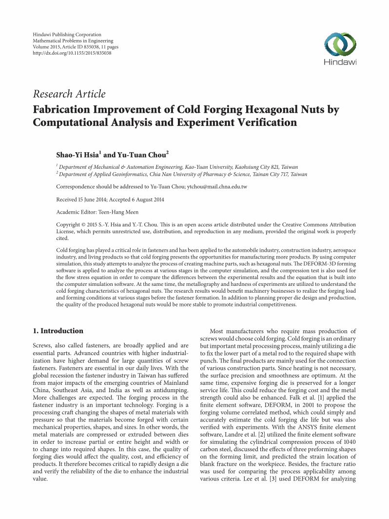
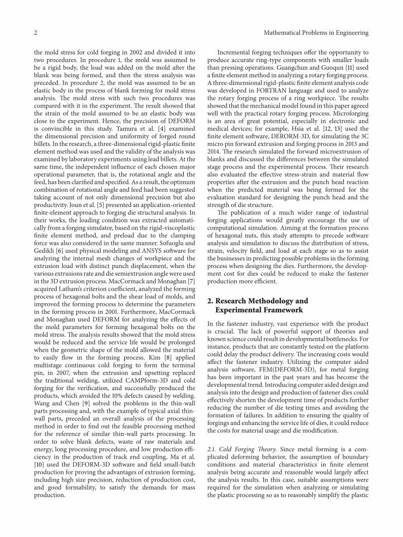
2.2. Experimental Steps. The computer simulation analysissoftware, SolidWorks, is applied to establish the 3D geometricmodel of dies and workpieces in this study. Figure 1 showsthe 5-stage product of the analyzed hexagonal nut; Figure 2displays the operation of die, punch pins, and forging work-piece, with 1/6 of the original shape. The first stage is thepreformation of hexagonal nut, the second stage is to changethe external shape of hexagonal nut, the third stage andthe fourth stage reveal large changes on punch pin, whichappear to show larger loads because of the hole preformationof hexagonal nut, and the fifth stage follows the processesof the previous two stages and continues the cold forgingdeformation till the final product size. For the analysis, thefigures are first transformed into STL files and then importedinto DEFORM-3D forming software for simulation. Theanalysis flow chart is shown in Figure 3, where the researchdirection is first determined and then the true materialsare acquired for the compression test in order to acquirethe flow stress for verification. The simulation analysis atvarious stages could be preceded when the experimentalresult is correct. The final results are compared with thefield processing in order to verify the feasibility of the entirecomputer simulation.
2.3. Compression Test. Theworkpieces proceeded in the com-pression experiment with a universal testing machine inorder to acquire the data of cold forging load and compressing
Figure 1: Finished products of the hexagonal nuts.
Die
Top punch pin
Workpiece
Bottom punch pin
Figure 2: Schematic diagram of the die construction.
steps, withwhich the true stress and true strain are calculated,the flow stress line graph is drawn with the Grapher software,and the equation is acquired with statistical regression.
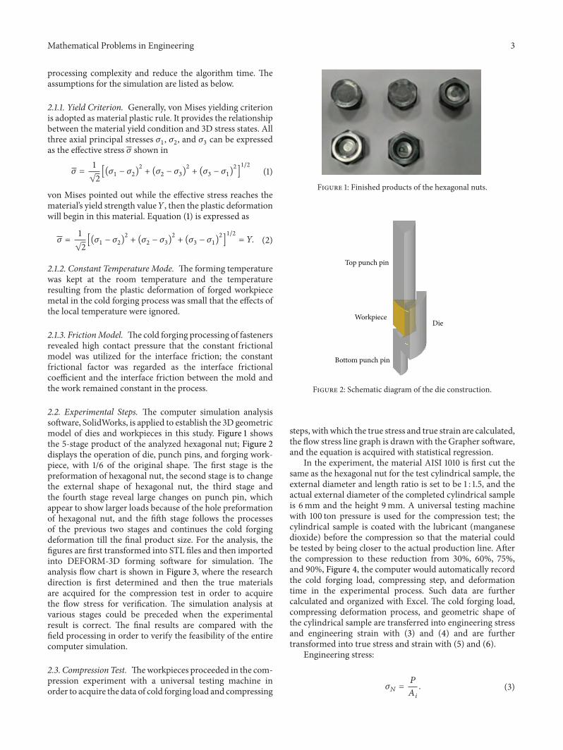
In the experiment, the material AISI 1010 is first cut thesame as the hexagonal nut for the test cylindrical sample, theexternal diameter and length ratio is set to be 1 : 1.5, and theactual external diameter of the completed cylindrical sampleis 6mm and the height 9mm. A universal testing machinewith 100 ton pressure is used for the compression test; thecylindrical sample is coated with the lubricant (manganesedioxide) before the compression so that the material couldbe tested by being closer to the actual production line. Afterthe compression to these reduction from 30%, 60%, 75%,and 90%, Figure 4, the computer would automatically recordthe cold forging load, compressing step, and deformationtime in the experimental process. Such data are furthercalculated and organized with Excel. The cold forging load,compressing deformation process, and geometric shape ofthe cylindrical sample are transferred into engineering stressand engineering strain with (3) and (4) and are furthertransformed into true stress and strain with (5) and (6).
Engineering stress:
𝜎𝑁=
𝑃
𝐴𝑖
. (3)
4 Mathematical Problems in Engineering
Analysis of cold forging fasteners and establishment of 3D model
Forming design at various passes
Design of forming die for each stage
Using DEFORM-3D to simulate the forming process
Determine the feasibility of forming design
Finish
Compressive tests
Determine research direction
Flow stress curve
Figure 3: Study of the flowchart.
Figure 4: Compressed cylindrical samples at 30%, 60%, 75%, and90% reductions.
Engineering strain:
𝜀𝑁=
ℎ𝑖− ℎ𝑓
ℎ𝑓
. (4)
True stress:
𝜎𝑡= 𝜎𝑁(1 − 𝑟) . (5)
True strain:
𝜀𝑡= − ln (1 − 𝑟) , (6)
where 𝑃 is compressing load, 𝐴𝑖and ℎ
𝑖are initial cross-
section area and height, ℎ𝑓is height at the deformation, and
𝑟 = (ℎ𝑖− ℎ𝑓)/ℎ𝑖is reduction. In the compression test, the
engineering strain and the reduction are equal; that is, 𝜀𝑁= 𝑟.
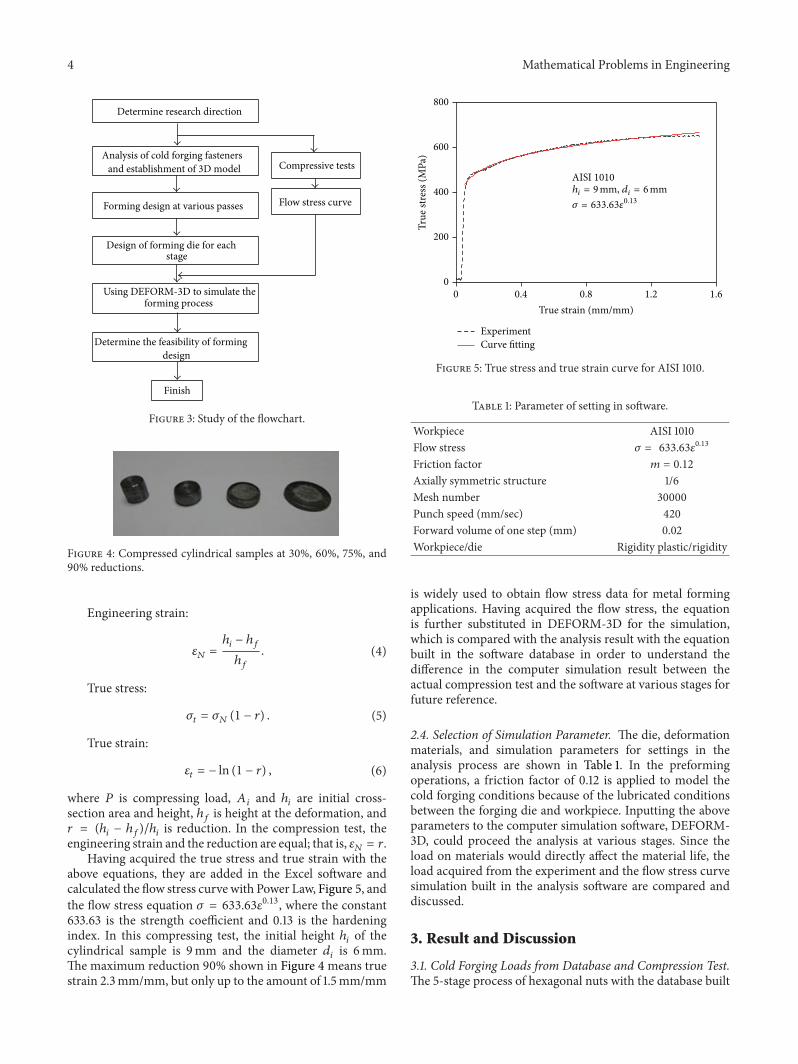
Having acquired the true stress and true strain with theabove equations, they are added in the Excel software andcalculated the flow stress curve with Power Law, Figure 5, andthe flow stress equation 𝜎 = 633.63𝜀0.13, where the constant633.63 is the strength coefficient and 0.13 is the hardeningindex. In this compressing test, the initial height ℎ
𝑖of the
cylindrical sample is 9mm and the diameter 𝑑𝑖is 6mm.
The maximum reduction 90% shown in Figure 4 means truestrain 2.3mm/mm, but only up to the amount of 1.5mm/mm
0
200
400
600
800
0 0.4 0.8 1.2 1.6
True
stre
ss (M
Pa)
True strain (mm/mm)
AISI 1010
Experiment
hi = 9mm, di = 6mm𝜎 = 633.63𝜀
0.13
Curve fitting
Figure 5: True stress and true strain curve for AISI 1010.
Table 1: Parameter of setting in software.
Workpiece AISI 1010Flow stress 𝜎 = 633.63𝜀
0.13
Friction factor 𝑚 = 0.12
Axially symmetric structure 1/6Mesh number 30000Punch speed (mm/sec) 420Forward volume of one step (mm) 0.02Workpiece/die Rigidity plastic/rigidity
is widely used to obtain flow stress data for metal formingapplications. Having acquired the flow stress, the equationis further substituted in DEFORM-3D for the simulation,which is compared with the analysis result with the equationbuilt in the software database in order to understand thedifference in the computer simulation result between theactual compression test and the software at various stages forfuture reference.
2.4. Selection of Simulation Parameter. The die, deformationmaterials, and simulation parameters for settings in theanalysis process are shown in Table 1. In the preformingoperations, a friction factor of 0.12 is applied to model thecold forging conditions because of the lubricated conditionsbetween the forging die and workpiece. Inputting the aboveparameters to the computer simulation software, DEFORM-3D, could proceed the analysis at various stages. Since theload on materials would directly affect the material life, theload acquired from the experiment and the flow stress curvesimulation built in the analysis software are compared anddiscussed.
3. Result and Discussion
3.1. Cold Forging Loads from Database and Compression Test.The 5-stage process of hexagonal nuts with the database built
Mathematical Problems in Engineering 5
Table 2: Cold forging loads for database and compression experiment.
1/6 Axially symmetric Stage 1 Stage 2 Stage 3 Stage 4 Stage 5Stroke (mm) 1.24 3.24 5.3 7.16 9.46Load (kN)
Database 12.92 31.01 40.99 40.39 19.26Experiment 13.36 29.68 36.34 39.61 19.55
Difference between database and experiment +0.436 −1.333 −4.652 −0.778 +0.289Percentage of difference (%) +3% −4% −11% −2% +2%
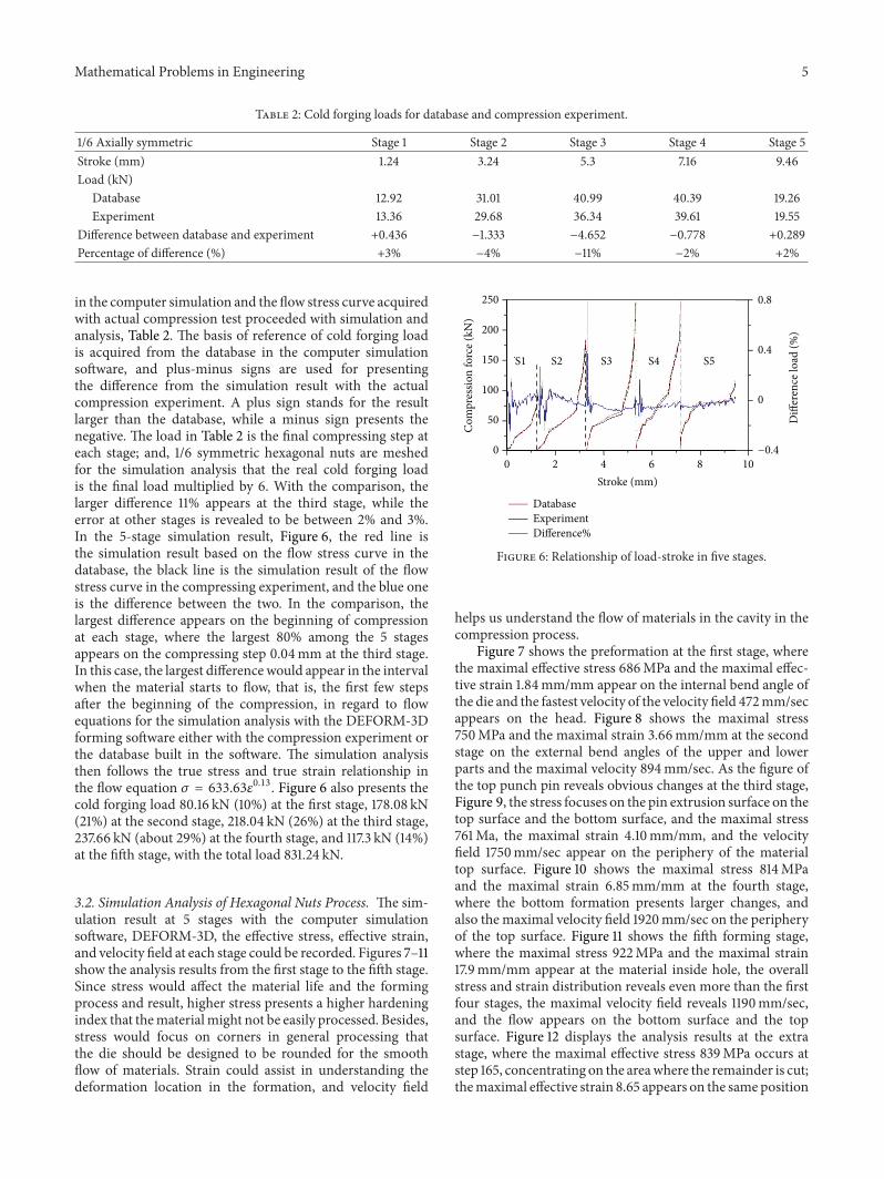
in the computer simulation and the flow stress curve acquiredwith actual compression test proceeded with simulation andanalysis, Table 2. The basis of reference of cold forging loadis acquired from the database in the computer simulationsoftware, and plus-minus signs are used for presentingthe difference from the simulation result with the actualcompression experiment. A plus sign stands for the resultlarger than the database, while a minus sign presents thenegative. The load in Table 2 is the final compressing step ateach stage; and, 1/6 symmetric hexagonal nuts are meshedfor the simulation analysis that the real cold forging loadis the final load multiplied by 6. With the comparison, thelarger difference 11% appears at the third stage, while theerror at other stages is revealed to be between 2% and 3%.In the 5-stage simulation result, Figure 6, the red line isthe simulation result based on the flow stress curve in thedatabase, the black line is the simulation result of the flowstress curve in the compressing experiment, and the blue oneis the difference between the two. In the comparison, thelargest difference appears on the beginning of compressionat each stage, where the largest 80% among the 5 stagesappears on the compressing step 0.04mm at the third stage.In this case, the largest difference would appear in the intervalwhen the material starts to flow, that is, the first few stepsafter the beginning of the compression, in regard to flowequations for the simulation analysis with the DEFORM-3Dforming software either with the compression experiment orthe database built in the software. The simulation analysisthen follows the true stress and true strain relationship inthe flow equation 𝜎 = 633.63𝜀0.13. Figure 6 also presents thecold forging load 80.16 kN (10%) at the first stage, 178.08 kN(21%) at the second stage, 218.04 kN (26%) at the third stage,237.66 kN (about 29%) at the fourth stage, and 117.3 kN (14%)at the fifth stage, with the total load 831.24 kN.
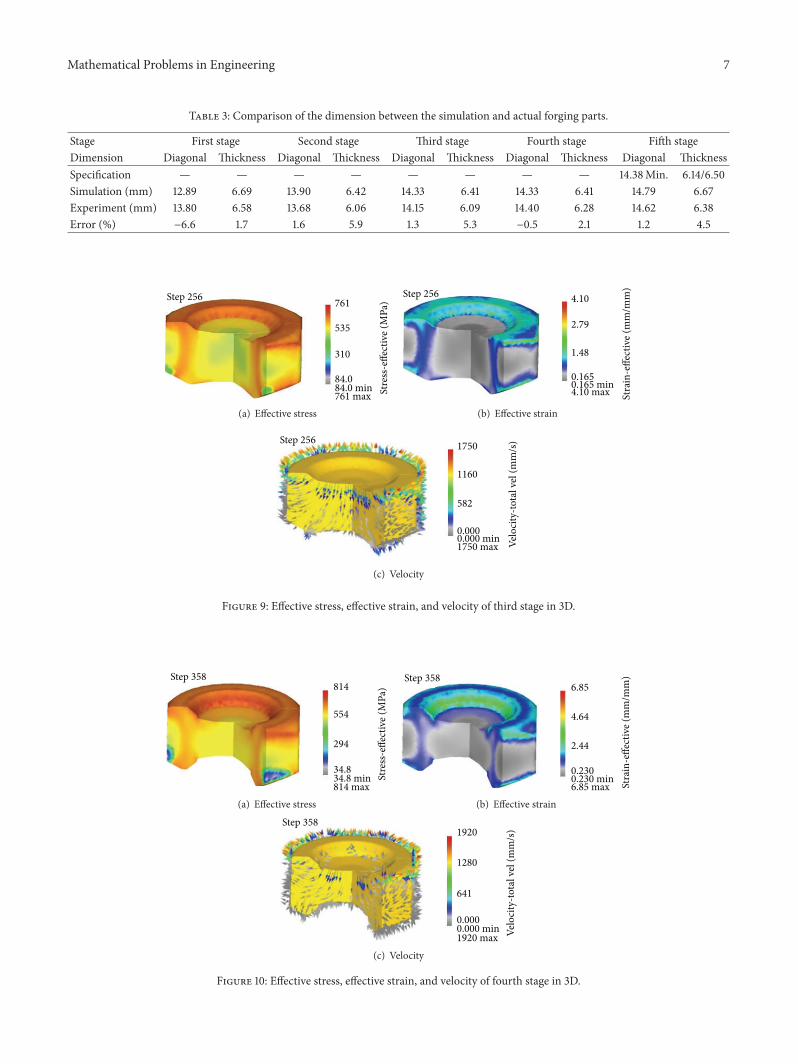
3.2. Simulation Analysis of Hexagonal Nuts Process. The sim-ulation result at 5 stages with the computer simulationsoftware, DEFORM-3D, the effective stress, effective strain,and velocity field at each stage could be recorded. Figures 7–11show the analysis results from the first stage to the fifth stage.Since stress would affect the material life and the formingprocess and result, higher stress presents a higher hardeningindex that thematerialmight not be easily processed. Besides,stress would focus on corners in general processing thatthe die should be designed to be rounded for the smoothflow of materials. Strain could assist in understanding thedeformation location in the formation, and velocity field
Stroke (mm)
Difference%ExperimentDatabase
150
200
250
00
50
100
2 4 6 8 10
0
0.4
0.8
Com
pres
sion
forc
e (kN
)
Diff
eren
ce lo
ad (%
)
−0.4
S1 S2 S3 S4 S5
Figure 6: Relationship of load-stroke in five stages.
helps us understand the flow of materials in the cavity in thecompression process.
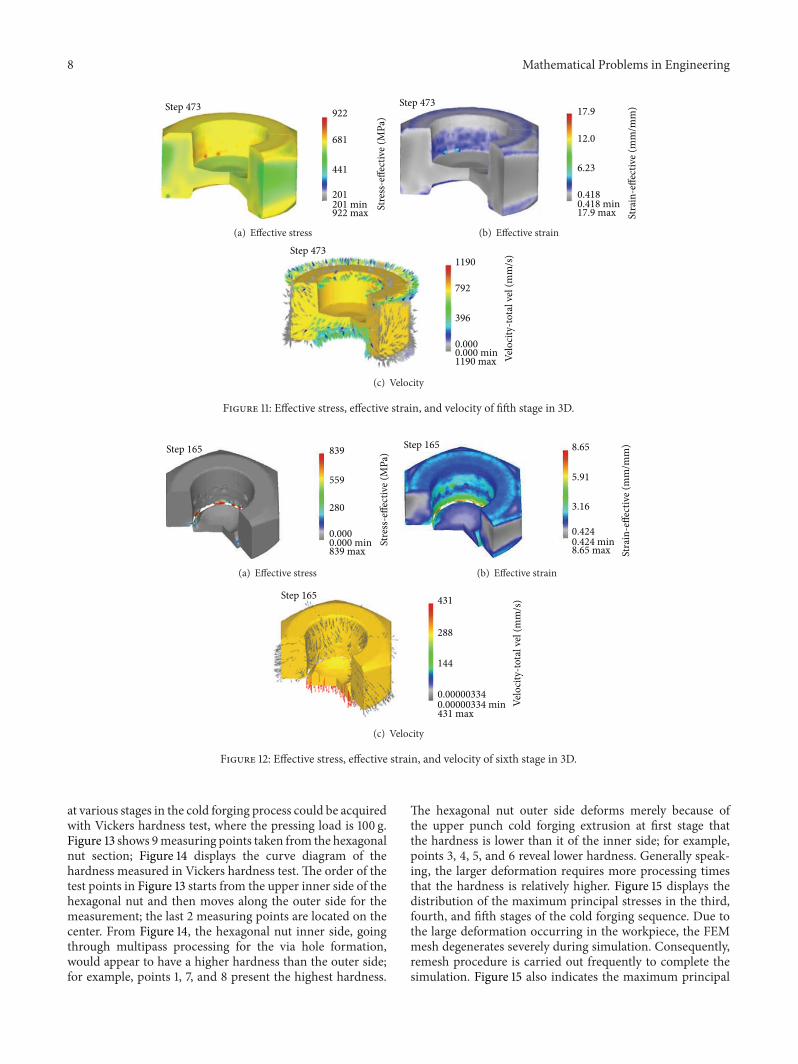
Figure 7 shows the preformation at the first stage, wherethe maximal effective stress 686MPa and the maximal effec-tive strain 1.84mm/mm appear on the internal bend angle ofthe die and the fastest velocity of the velocity field 472mm/secappears on the head. Figure 8 shows the maximal stress750MPa and the maximal strain 3.66mm/mm at the secondstage on the external bend angles of the upper and lowerparts and the maximal velocity 894mm/sec. As the figure ofthe top punch pin reveals obvious changes at the third stage,Figure 9, the stress focuses on the pin extrusion surface on thetop surface and the bottom surface, and the maximal stress761Ma, the maximal strain 4.10mm/mm, and the velocityfield 1750mm/sec appear on the periphery of the materialtop surface. Figure 10 shows the maximal stress 814MPaand the maximal strain 6.85mm/mm at the fourth stage,where the bottom formation presents larger changes, andalso the maximal velocity field 1920mm/sec on the peripheryof the top surface. Figure 11 shows the fifth forming stage,where the maximal stress 922MPa and the maximal strain17.9mm/mm appear at the material inside hole, the overallstress and strain distribution reveals even more than the firstfour stages, the maximal velocity field reveals 1190mm/sec,and the flow appears on the bottom surface and the topsurface. Figure 12 displays the analysis results at the extrastage, where the maximal effective stress 839MPa occurs atstep 165, concentrating on the areawhere the remainder is cut;themaximal effective strain 8.65 appears on the sameposition

6 Mathematical Problems in Engineering
571
456
686Step 62
686 max341 min341
Stre
ss-e
ffect
ive (
MPa
)
(a) Effective stress
Step 62
Stra
in-e
ffect
ive (
mm
/mm
)
1.84
1.23
0.615
0.003801.84 max0.00380 min
(b) Effective strain
315
157
0.000 min472 max
0.000
Velo
city
-tota
l vel
(mm
/s)
472Step 62
(c) Velocity
Figure 7: Effective stress, effective strain, and velocity of first stage in 3D.
647
544
441441 min750 max
Step 162
Stre
ss-e
ffect
ive (
MPa
)750
(a) Effective stress
3.66
2.46
1.26
0.06113.66 max0.0611 min
Step 162
Stra
in-e
ffect
ive (
mm
/mm
)
(b) Effective strain
0.000 min894 max
894
596
298
0.000
Velo
city
-tota
l vel
(mm
/s)Step 162
(c) Velocity
Figure 8: Effective stress, effective strain, and velocity of second stage in 3D.
as the maximal effective stress; and themaximal velocity field431mm/sec appears on the bottom area after cutting the holeflat. From the above simulation results, the hexagonal nutshape shows the greatest change at the fifth stage that themaximal effective stress and effective strain occur at the stage,and the maximal velocity field appears on the fourth stage.
Table 3 indicated the comparison of the simulative andexperimental dimensions on the different stages of the coldforging hexagonal nut. Only the sizes of the diagonal andthickness are discussed in this study. Because 1/6 symmetricmesh is set in the simulation, the dimensions of 𝑦-axisindicate diagonal and 𝑧-axis mean thickness. The simulativeresults are obtained from the analysis of DEFORM-3D, andexperimental dimensions of the different forging sequences
from a workpiece metal to the finishing stage are measuredas shown in Figure 1. From Table 3, the percentages of errorare no more than 6.6%, for example, the maximum on thediagonal dimension of the first stage.
3.3. Cold Forging Characteristics of Actual Forging Parts. Tounderstand the correctness of the previous simulation ofcold forging hexagonal nuts, the analysis results are precededby the die design and then the cold forged hexagonal nutstested the hardness and metallography in order to confirmthe effects of stress, strain, and velocity field on the formedhexagonal nuts for future modification. In this study, theeffects on themost importantmechanical property, hardness,
Mathematical Problems in Engineering 7
Table 3: Comparison of the dimension between the simulation and actual forging parts.
Stage First stage Second stage Third stage Fourth stage Fifth stageDimension Diagonal Thickness Diagonal Thickness Diagonal Thickness Diagonal Thickness Diagonal ThicknessSpecification — — — — — — — — 14.38Min. 6.14/6.50Simulation (mm) 12.89 6.69 13.90 6.42 14.33 6.41 14.33 6.41 14.79 6.67Experiment (mm) 13.80 6.58 13.68 6.06 14.15 6.09 14.40 6.28 14.62 6.38Error (%) −6.6 1.7 1.6 5.9 1.3 5.3 −0.5 2.1 1.2 4.5
535
84.0
761Step 256
Stre
ss-e
ffect
ive (
MPa
)
310
84.0 min761 max
(a) Effective stress
Stra
in-e
ffect
ive (
mm
/mm
)
4.10
2.79
1.48
0.1650.165 min
Step 256
4.10 max
(b) Effective strain
Velo
city
-tota
l vel
(mm
/s)1750
1160
582
0.0000.000 min
Step 256
1750 max
(c) Velocity
Figure 9: Effective stress, effective strain, and velocity of third stage in 3D.
Step 358
Stre
ss-e
ffect
ive (
MPa
)814
554
294
34.834.8 min814 max
(a) Effective stress
Step 3586.85
4.64
2.44
0.2300.230 min St
rain
-effe
ctiv
e (m
m/m
m)
6.85 max(b) Effective strain
Velo
city
-tota
l vel
(mm
/s)
Step 3581920
1280
641
0.0000.000 min1920 max
(c) Velocity
Figure 10: Effective stress, effective strain, and velocity of fourth stage in 3D.
8 Mathematical Problems in Engineering
Step 473 922
681
441
201
Stre
ss-e
ffect
ive (
MPa
)
922 max201 min
(a) Effective stress
Step 47317.9
12.0
6.23
0.4180.418 min
Stra
in-e
ffect
ive (
mm
/mm
)
17.9 max
(b) Effective strain
1190 max Velo
city
-tota
l vel
(mm
/s)1190
792
396
0.0000.000 min
Step 473
(c) Velocity
Figure 11: Effective stress, effective strain, and velocity of fifth stage in 3D.
Step 165
Stre
ss-e
ffect
ive (
MPa
)839
559
280
0.0000.000 min839 max
(a) Effective stress
8.65
5.91
3.16
0.4240.424 min
Step 165
8.65 max Stra
in-e
ffect
ive (
mm
/mm
)
(b) Effective strain
431
431 max
Step 165
144
288
0.000003340.00000334 min Ve
loci
ty-to
tal v
el (m
m/s
)
(c) Velocity
Figure 12: Effective stress, effective strain, and velocity of sixth stage in 3D.
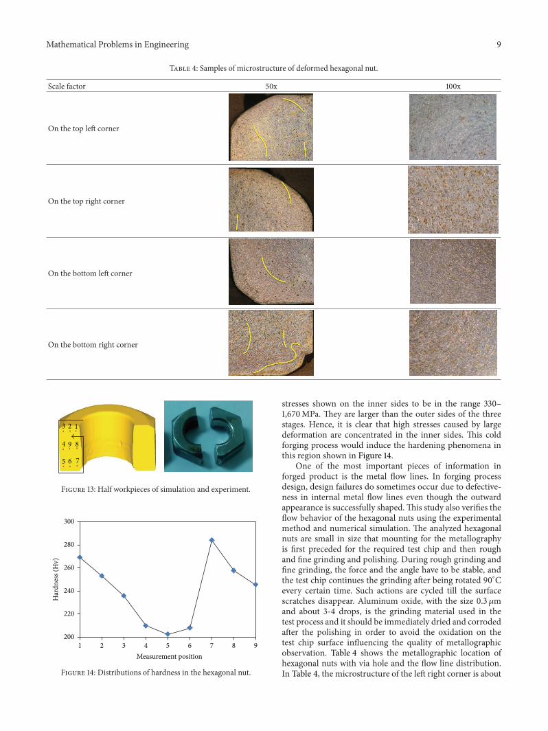
at various stages in the cold forging process could be acquiredwith Vickers hardness test, where the pressing load is 100 g.Figure 13 shows 9measuring points taken from the hexagonalnut section; Figure 14 displays the curve diagram of thehardness measured in Vickers hardness test. The order of thetest points in Figure 13 starts from the upper inner side of thehexagonal nut and then moves along the outer side for themeasurement; the last 2 measuring points are located on thecenter. From Figure 14, the hexagonal nut inner side, goingthrough multipass processing for the via hole formation,would appear to have a higher hardness than the outer side;for example, points 1, 7, and 8 present the highest hardness.
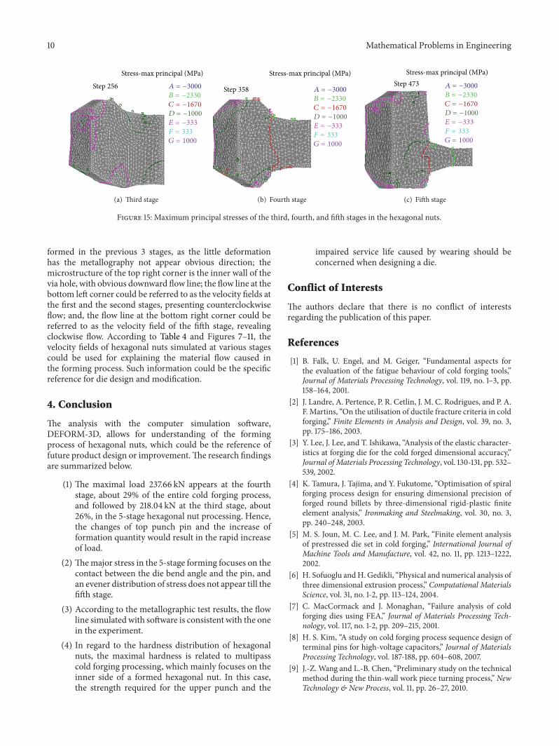
The hexagonal nut outer side deforms merely because ofthe upper punch cold forging extrusion at first stage thatthe hardness is lower than it of the inner side; for example,points 3, 4, 5, and 6 reveal lower hardness. Generally speak-ing, the larger deformation requires more processing timesthat the hardness is relatively higher. Figure 15 displays thedistribution of the maximum principal stresses in the third,fourth, and fifth stages of the cold forging sequence. Due tothe large deformation occurring in the workpiece, the FEMmesh degenerates severely during simulation. Consequently,remesh procedure is carried out frequently to complete thesimulation. Figure 15 also indicates the maximum principal
Mathematical Problems in Engineering 9
Table 4: Samples of microstructure of deformed hexagonal nut.
Scale factor 50x 100x
On the top left corner
On the top right corner
On the bottom left corner
On the bottom right corner
23 1
89
76
4
5
Figure 13: Half workpieces of simulation and experiment.
200
220
240
260
280
300
1 2 3 4 5 6 7 8 9
Har
dnes
s (H
v)
Measurement position
Figure 14: Distributions of hardness in the hexagonal nut.
stresses shown on the inner sides to be in the range 330–1,670MPa. They are larger than the outer sides of the threestages. Hence, it is clear that high stresses caused by largedeformation are concentrated in the inner sides. This coldforging process would induce the hardening phenomena inthis region shown in Figure 14.
One of the most important pieces of information inforged product is the metal flow lines. In forging processdesign, design failures do sometimes occur due to defective-ness in internal metal flow lines even though the outwardappearance is successfully shaped.This study also verifies theflow behavior of the hexagonal nuts using the experimentalmethod and numerical simulation. The analyzed hexagonalnuts are small in size that mounting for the metallographyis first preceded for the required test chip and then roughand fine grinding and polishing. During rough grinding andfine grinding, the force and the angle have to be stable, andthe test chip continues the grinding after being rotated 90∘Cevery certain time. Such actions are cycled till the surfacescratches disappear. Aluminum oxide, with the size 0.3 𝜇mand about 3-4 drops, is the grinding material used in thetest process and it should be immediately dried and corrodedafter the polishing in order to avoid the oxidation on thetest chip surface influencing the quality of metallographicobservation. Table 4 shows the metallographic location ofhexagonal nuts with via hole and the flow line distribution.In Table 4, the microstructure of the left right corner is about
10 Mathematical Problems in Engineering
Stress-max principal (MPa)
Step 256 A = −3000
B = −2330
C = −1670
D = −1000
E = −333
F = 333
G = 1000
(a) Third stage
Stress-max principal (MPa)
Step 358 A = −3000
B = −2330
C = −1670
D = −1000
E = −333
F = 333
G = 1000
(b) Fourth stage
Stress-max principal (MPa)Step 473 A = −3000
B = −2330
C = −1670
D = −1000
E = −333
F = 333
G = 1000
(c) Fifth stage
Figure 15: Maximum principal stresses of the third, fourth, and fifth stages in the hexagonal nuts.
formed in the previous 3 stages, as the little deformationhas the metallography not appear obvious direction; themicrostructure of the top right corner is the inner wall of thevia hole, with obvious downward flow line; the flow line at thebottom left corner could be referred to as the velocity fields atthe first and the second stages, presenting counterclockwiseflow; and, the flow line at the bottom right corner could bereferred to as the velocity field of the fifth stage, revealingclockwise flow. According to Table 4 and Figures 7–11, thevelocity fields of hexagonal nuts simulated at various stagescould be used for explaining the material flow caused inthe forming process. Such information could be the specificreference for die design and modification.
4. Conclusion
The analysis with the computer simulation software,DEFORM-3D, allows for understanding of the formingprocess of hexagonal nuts, which could be the reference offuture product design or improvement.The research findingsare summarized below.
(1) The maximal load 237.66 kN appears at the fourthstage, about 29% of the entire cold forging process,and followed by 218.04 kN at the third stage, about26%, in the 5-stage hexagonal nut processing. Hence,the changes of top punch pin and the increase offormation quantity would result in the rapid increaseof load.
(2) Themajor stress in the 5-stage forming focuses on thecontact between the die bend angle and the pin, andan evener distribution of stress does not appear till thefifth stage.
(3) According to the metallographic test results, the flowline simulated with software is consistent with the onein the experiment.
(4) In regard to the hardness distribution of hexagonalnuts, the maximal hardness is related to multipasscold forging processing, which mainly focuses on theinner side of a formed hexagonal nut. In this case,the strength required for the upper punch and the
impaired service life caused by wearing should beconcerned when designing a die.
Conflict of Interests
The authors declare that there is no conflict of interestsregarding the publication of this paper.
References
[1] B. Falk, U. Engel, and M. Geiger, “Fundamental aspects forthe evaluation of the fatigue behaviour of cold forging tools,”Journal of Materials Processing Technology, vol. 119, no. 1–3, pp.158–164, 2001.
[2] J. Landre, A. Pertence, P. R. Cetlin, J. M. C. Rodrigues, and P. A.F. Martins, “On the utilisation of ductile fracture criteria in coldforging,” Finite Elements in Analysis and Design, vol. 39, no. 3,pp. 175–186, 2003.
[3] Y. Lee, J. Lee, and T. Ishikawa, “Analysis of the elastic character-istics at forging die for the cold forged dimensional accuracy,”Journal of Materials Processing Technology, vol. 130-131, pp. 532–539, 2002.
[4] K. Tamura, J. Tajima, and Y. Fukutome, “Optimisation of spiralforging process design for ensuring dimensional precision offorged round billets by three-dimensional rigid-plastic finiteelement analysis,” Ironmaking and Steelmaking, vol. 30, no. 3,pp. 240–248, 2003.
[5] M. S. Joun, M. C. Lee, and J. M. Park, “Finite element analysisof prestressed die set in cold forging,” International Journal ofMachine Tools and Manufacture, vol. 42, no. 11, pp. 1213–1222,2002.
[6] H. Sofuoglu andH. Gedikli, “Physical and numerical analysis ofthree dimensional extrusion process,” Computational MaterialsScience, vol. 31, no. 1-2, pp. 113–124, 2004.
[7] C. MacCormack and J. Monaghan, “Failure analysis of coldforging dies using FEA,” Journal of Materials Processing Tech-nology, vol. 117, no. 1-2, pp. 209–215, 2001.
[8] H. S. Kim, “A study on cold forging process sequence design ofterminal pins for high-voltage capacitors,” Journal of MaterialsProcessing Technology, vol. 187-188, pp. 604–608, 2007.
[9] J.-Z. Wang and L.-B. Chen, “Preliminary study on the technicalmethod during the thin-wall work piece turning process,” NewTechnology & New Process, vol. 11, pp. 26–27, 2010.
Mathematical Problems in Engineering 11
[10] T. Ma, B. Liu, and H. Lin, “Study of ends connection preciseforming process,” New Technology & New Process, vol. 11, pp.106–109, 2010.
[11] W. Guangchun and Z. Guoqun, “Simulation and analysis ofrotary forging a ring workpiece using finite element method,”Finite Elements in Analysis and Design, vol. 38, no. 12, pp. 1151–1164, 2002.
[12] S.-Y. Hsia, “Optimization of microextrusion preforming usingTaguchi method,” Mathematical Problem in Engineering, vol.2013, Article ID 305797, 9 pages, 2013.
[13] S.-Y. Hsia, C.-C. Chang, W.-S. Huang, and Y.-C. Kuo, “Effect ofpreforms on extrusion die filling ofmicro brass pin,” Innovation,Communication and Engineering, 2014.

Submit your manuscripts athttp://www.hindawi.com
Hindawi Publishing Corporationhttp://www.hindawi.com Volume 2014
MathematicsJournal of
Hindawi Publishing Corporationhttp://www.hindawi.com Volume 2014
Mathematical Problems in Engineering
Hindawi Publishing Corporationhttp://www.hindawi.com
Differential EquationsInternational Journal of
Volume 2014
Applied MathematicsJournal of
Hindawi Publishing Corporationhttp://www.hindawi.com Volume 2014
Probability and StatisticsHindawi Publishing Corporationhttp://www.hindawi.com Volume 2014
Journal of
Hindawi Publishing Corporationhttp://www.hindawi.com Volume 2014
Mathematical PhysicsAdvances in
Complex AnalysisJournal of
Hindawi Publishing Corporationhttp://www.hindawi.com Volume 2014
OptimizationJournal of
Hindawi Publishing Corporationhttp://www.hindawi.com Volume 2014
CombinatoricsHindawi Publishing Corporationhttp://www.hindawi.com Volume 2014
International Journal of
Hindawi Publishing Corporationhttp://www.hindawi.com Volume 2014
Operations ResearchAdvances in
Journal of
Hindawi Publishing Corporationhttp://www.hindawi.com Volume 2014
Function Spaces
Abstract and Applied AnalysisHindawi Publishing Corporationhttp://www.hindawi.com Volume 2014
International Journal of Mathematics and Mathematical Sciences
Hindawi Publishing Corporationhttp://www.hindawi.com Volume 2014
The Scientific World JournalHindawi Publishing Corporation http://www.hindawi.com Volume 2014
Hindawi Publishing Corporationhttp://www.hindawi.com Volume 2014
Algebra
Discrete Dynamics in Nature and Society
Hindawi Publishing Corporationhttp://www.hindawi.com Volume 2014
Hindawi Publishing Corporationhttp://www.hindawi.com Volume 2014
Decision SciencesAdvances in
Discrete MathematicsJournal of
Hindawi Publishing Corporationhttp://www.hindawi.com
Volume 2014 Hindawi Publishing Corporationhttp://www.hindawi.com Volume 2014
Stochastic AnalysisInternational Journal of