research article design of compact trapezoidal bow-tie
TRANSCRIPT

Research ArticleDesign of Compact Trapezoidal Bow-Tie Chipless RFID Tag
Lei Xu and Kama Huang
School of Electronics and Information Engineering, Sichuan University, Chengdu 610064, China
Correspondence should be addressed to Kama Huang; [email protected]
Received 23 July 2014; Accepted 17 October 2014
Academic Editor: Antonio Faraone
Copyright © 2015 L. Xu and K. Huang.This is an open access article distributed under the Creative Commons Attribution License,which permits unrestricted use, distribution, and reproduction in any medium, provided the original work is properly cited.
This paper presents a novel compact design of a low cost fully printable slot-loaded bowtie chipless RFID tag. The tag consistsof two trapezoidal metallic patches loaded with multiple slot resonators. Slots with similar size or adjacent frequencies are loadedalternately on two bow-tie patches to double the number of data bits within theUWB frequency bandwithout increasing themutualcoupling between slots. A coding capacity of 12 bits is obtained with 12 slots within a reasonable size of 35mm × 33mm. RCS ofthe tag has been given by simulation. Measurements have been done using a bistatic radar configuration in the frequency domainand transmission coefficient is measured. The agreement between the simulation and measurement validates this new concept ofdesign.This tag has high data capacity and low cost and can be directly printed on product such as personal ID, credit cards, paper,and textile because it needs only one conductive layer.
1. Introduction
Radio frequency identification (RFID) is an automatic iden-tification technology that uses EM waves to extract encodeddata from remote tags [1, 2]. The RFID tag has someadvantages over the current mainstream optical barcode[3], such as longer reading range, non-line-of-sight reading,and automated identification and tracking, and consequentlyhas the potential to replace the barcode [4]. However, con-ventional RFID tag contains silicon chip and antenna andthus has higher cost, making it difficult to compete withthe low cost barcode technology. Therefore, research efforthas been focused on another promising candidate, that is,chipless RFID tag, which would not require any chip norcommunication protocol and can be used like barcode. Theconcept of RF barcode was firstly introduced by Jalaly andRobertson [5], and then it was developed worldwide [6].A chipless tag acts as a transmitting antenna, a receivingantenna, and a filter simultaneously. However, the tagwithoutchip is inflexible to encode high density data on it. Increasingdata capacity, enhancing robustness, and reducing size andcost are the current challenges of designing chipless tag.
At present, there are various designs of chipless RFID tags,which can be classified according to their encoding method.Some tags are encoded in the time domain [5, 7, 8], while
others are encoded in frequency domain [9–12]. Frequencydomain-based tags have higher data density and are moreeasily to be miniaturized than time domain-based tags. A 3-bit notched elliptical dipole tag has been presented in [13]and the singularity based encoding is firstly applied in RFIDtag, but the coding capacity of this tag is too low to be usedoutside the lab. Hybrid coding technique for chipless taghas been presented in [14] with coding capacity up to 23bits, but the required frequency resolution cannot be easilyimplemented for data encoding. A chipless tag consisting ofmultiple stopband spiral resonators and two cross polarizedUWB antennas has been presented in [15]. A 16-bit fullyprintable slot-loaded dual-polarized chipless RFID tag hasbeen presented in [16] with improving coding efficiency withthe aid of a pair of dual-polarized antennas.
In this paper, a bow-tie chipless RFID tag is presented.It consists of two symmetrical trapezoidal metallic patchesloaded with 12 pairs of slot resonators corresponding to 12-bit data. High data capacity is achieved by the tapering lengthof slot resonators loaded on a patch. This compact tag has areasonable physical size of 35mm × 33mm and it operateswithin the UWB frequency band. Higher data capacity canbe obtained by adjusting the width of the slot and the metalstrip. Compared with other designs, the proposed design ismore compact and easier to be implemented.
Hindawi Publishing CorporationInternational Journal of Antennas and PropagationVolume 2015, Article ID 502938, 7 pageshttp://dx.doi.org/10.1155/2015/502938

2 International Journal of Antennas and Propagation
L
W
E
H
L = 𝜆/4
g
(a)
6.5 7 7.5 8 8.5 90
2
4
6
8
ID-111111
×10−4
RCS
mag
nitu
de
Frequency (GHz)
(b)
6.5 7 7.5 8 8.5 9Frequency (GHz)
RCS
phas
e (de
g.)
ID-111111
−30
−40
−50
−60
−70
(c)
Figure 1: (a) Basic resonance element using slot resonator, the dimensions are 𝐿 = 8.5mm,𝑊 = 1.5mm, and 𝑔 = 0.5mm. (b) Magnitudeversus frequency response of slot resonator. (c) Phase versus frequency response of slot resonator.
The rest of the paper is organized as follows: Section 2presents operating principle of the proposed chipless RFIDtag. Section 3 presents the design and simulation of thetag. Section 4 presents measurement results compared tosimulations followed by conclusion in Section 5.
2. Basic Principle
2.1. Principle of the Loaded Resonator. A metallic patchloaded with several slot resonators can create a radar crosssection (RCS) with some sharp notches or peaks at specificfrequencies in the backscattering signal, and these notches orpeaks can be used to encode data within a frequency band.
A single slot resonator used in the proposed tag, shownin Figure 1(a), is a planar strip having a length 𝐿 and agap width 𝑔. One side of the slot is shorted; the other sideis open. When the guided quarter wavelength matches thephysical length 𝐿, a quarter wavelength standing wave modesis excited by an incident vertical polarized electromagneticwave perpendicular to this asymmetrical slot, and a min-imum surface current is induced on the open side of theslot resonator and a maximum surface current is inducedon the short side. The magnitude-frequency response andphase-frequency response are shown in Figures 1(b) and1(c), respectively. Furthermore, the capacitive effect betweentwo arms of the slot resonator increases the quality of theresonator. A narrow band resonance cannot be excited onthis tag by a horizontal polarized wave. In addition to aresonance, there is an antiresonance which comes from thespatial cancellation of the fields. The antiresonance relies
on the polarization and incident angle of the exciting wave[17]. This resonator has intrinsically a resonant peak and anantiresonant dip in its spectrum, which can be used to encodedata.
The resonant frequency of the slot resonator can beestimated using [18]
𝑓𝑟=
𝑐
2𝐿
√
2
1 + 𝜀𝑟
. (1)
Here, 𝑐 is the speed of light and 𝜀𝑟is the relative permittivity
of the substrate. Besides, the gap width 𝑔 also has a slightinfluence on the resonance frequency. Considering these twofactors, the resonant frequency of the slot resonator dependson the length 𝐿+𝑔/2. Quality factor of the slot is proportionalto the ratio 𝐿/𝑔. Therefore, the resonant frequency andquality factor can be easily adjusted by the slot length 𝐿 andgap width 𝑔, respectively. One or more slots can be loaded ona metallic patch, and one or more slots of the resonator canbe shorted and the corresponding frequencies are thus nulled,and a data bit 0 or 1 can be encoded according to the presenceor absence of a peak or dip in the spectrum.The encoding ruleused in this paper is very simple: the presence or absence ofthe dip presents data bit 1 or 0, respectively.
2.2. Operating Principle of the Proposed Chipless RFID Tag.Figure 2 shows the operating principle of the proposedRFID tag. When the chipless RFID tag is impinged by avertically polarized EM wave from the transmitter antenna,a unique frequency signature is excited, and the receiverantenna receives the encoded backscattered signal.The RFID

International Journal of Antennas and Propagation 3
RFID chipless tag
RFIDreader
111101
Tx
Rx
Figure 2: Principle of operation.
reader or measurement device records and extracts thisunique frequency signature, and the chipless RFID tag is thusidentified.
3. Design and Simulation of the Chipless Tag
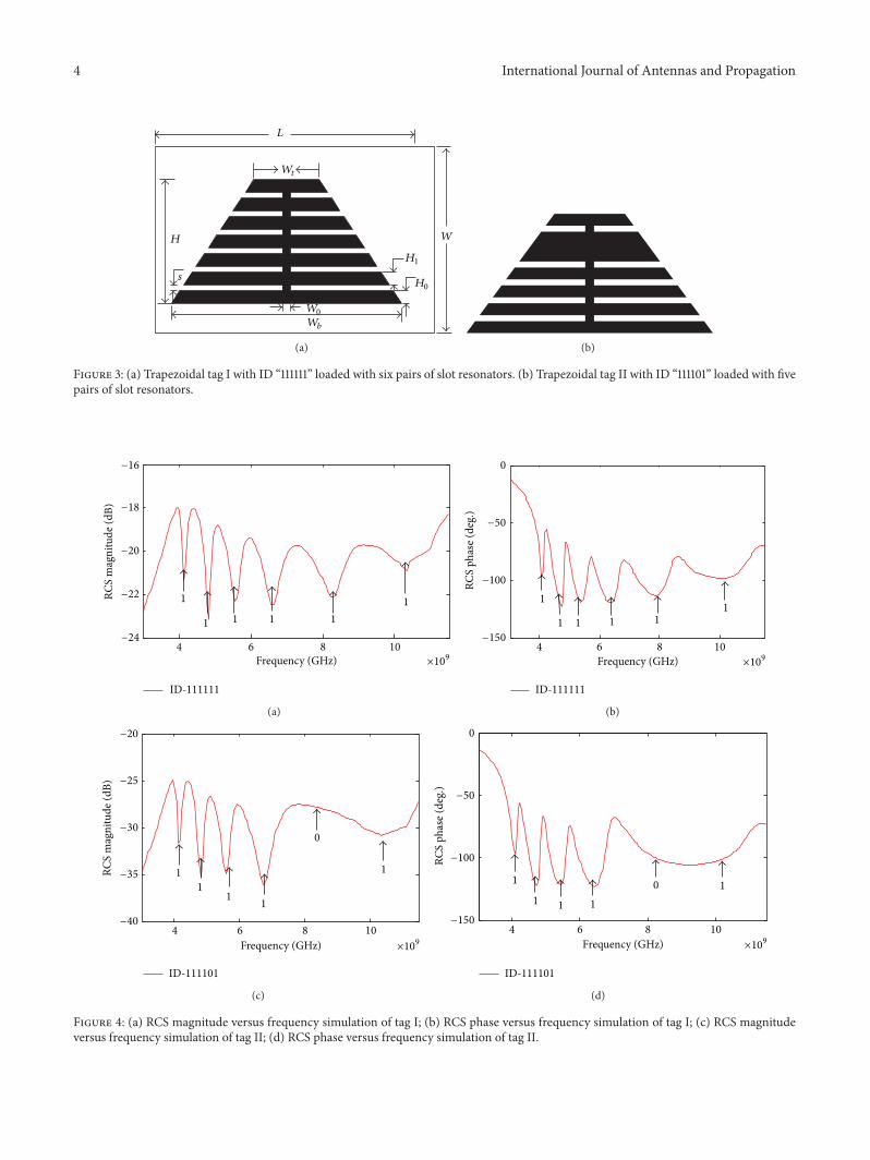
The configuration of the proposed trapezoidal chipless RFIDtag I and tag II is depicted in Figure 3.
A trapezoidal metallic patch with bottom width𝑊𝑏, top
width 𝑊𝑡, and height 𝐻 acts as a carrier of slot resonators.
Six pairs of quarter-wavelength open-ended slot resonatorswith different length 𝐿
𝑖(𝑖 = 1, 2, 3, 4, 5, 6) are loaded on the
trapezoidal metallic patch.The 6 pairs of slot resonators withdifferent physical dimensions create 6 peaks and 6 dips inspectrum corresponding to 6 resonant frequencies. The sixphysical slots with different length from the longest to theshortest create six quarter-wavelength resonances, and thecorresponding frequencies, from the lowest to the highest, are4.1 GHz, 4.8GHz, 5.8GHz, 6.5 GHz, 8.3 GHz, and 10.3 GHz.In order to facilitate the fabrication, the width 𝑠 of the slot ofthese resonators keeps the same size of 0.5mm. Simulationresults are shown in Figure 4.
The coding principle used for this tag is very simple: eachresonant frequency has a peak and dip in spectrum, and thedip is chosen to encode 1 data bit. Six dips are seen in themagnitude response for six 1’s of the tag with ID “111111,” whilefive dips are seen for five 1’s as opposed to no dip for the 0in the magnitude response for the tag with ID “111101.” Sixphase jumps are seen in the phase response for the tag withID “111111,” but no phase jumps for the 0 for the tag with ID“111101.” The phase response can double check the magnituderesponse.
Although higher data capacity can be obtained by loadingmore slot resonators, there exists mutual coupling of con-siderable strength between adjacent resonators when the slotresonators are located close to each other. Therefore, to dou-ble the data bits without increasing mutual coupling betweenadjacent slots, two identical metallic patches are placedsymmetrically on the substrate. Six pairs of slot resonatorson the right patch remain unchanged and the length of thesix pairs of slot resonators is 𝐿
𝑖(𝑖 = 1, 2, 3, 4, 5, 6), while six
pairs of slot resonators on the left patch are integrally shifted1mm to the top side of the trapezoid patch, and the length ofthese six pairs of slot resonators is 𝐿
𝑖(𝑖 = 7, 8, 9, 10, 11, 12).
Figure 5 shows the proposed bow-tie chipless tag III and
Table 1: Fabricated tag dimension in mm.
Tag Encoded data 𝐿 𝑊 𝐻 𝐻0𝐻1𝑊0𝑊𝑡𝑊𝑏𝑠
I 111111 33 1814 2 1.5 1 6 28 0.5II 111101
III 111111111111 35 33IV 011111111110
tag IV. The twelve physical slots with different length fromthe longest to the shortest create twelve quarter-wavelengthresonances, and the corresponding frequencies, from thelowest to the highest, are shown in Figure 6.
One bit data correspond to one frequency. Therefore,the tag can present 12-bit data and has a unique frequencysignature. To configure the tag, each slot resonator can beshorted or not depending on the encoded data. The presenceand absence of a given frequency band present data bits 1 and0, respectively.
When all of these slots keep unfilled, the 12-bit tagrepresents ID1: 111111111111, as shown in Figure 5(a). Whensome of these slot are shorted, the relevant frequencies willbe nulled; for example, when the longest slot on the left side,that is, 𝐿
1, and the shortest slot on the right side, that is, 𝐿
12,
are filled, this tag represents ID2: 011111111110, as shown inFigure 5(b). In our case, there is no ground plane, and thesize of this structure is nearly 35mm × 33mm.
4. Fabrication and Measurements
For the measurement, four tags with different ID have beenfabricated. The fabricated tags are illustrated in Figure 7 andthe dimensions of the tags are shown in Table 1. The tags areimplemented on a FR-4 substrate with a permittivity of 4.4,a loss tangent of 0.023, and a thickness of 0.5mm. FR-4 is aversatile and usually a low cost substrate and the fabricationprocess is based on copper etching.
The measurement may be done in anechoic chamber orin real office environment with tables, walls, and variouswireless devices. A bistatic radar system is used to detectdata encoded in the chipless tag. The measurement systemis composed of a vector network analyzer (VNA) AV3629Dwith an output power of 0 dBm in the entire measurementfrequency band, connected to two identical UWB hornantennas having a minimum 10 dB of gain in the frequencyband from 3.1 to 10.6GHz.The two antennas are placed 10 cmaway from each other and the tag under test is placed 15 cmfrom two antennas as shown in Figure 8. The transmittingantenna excites the resonators of the tag and the receivingantenna receives its EM signature as for a bistatic radarsystem.
The transmission coefficient 𝑆21is measured and plotted
against frequency in Figure 9. Due to fabrication error andmeasurement error, the measuring resonance frequencies areshifted slightly from the simulating resonance frequencies.Here, the frequency shift is within the ±200MHz bandaround the designed frequency. Therefore, the binary IDsstill can be extracted from the four tags properly, and the
4 International Journal of Antennas and Propagation
H
L
W
s
Wt
W0
Wb
H0
H1
(a) (b)
Figure 3: (a) Trapezoidal tag I with ID “111111” loaded with six pairs of slot resonators. (b) Trapezoidal tag II with ID “111101” loaded with fivepairs of slot resonators.
4 6 8 10Frequency (GHz)
RCS
mag
nitu
de (d
B)
ID-111111
11
11 1 1−24
−16
−18
−20
−22
×109
(a)
ID-111111
4 6 8 10Frequency (GHz)
RCS
phas
e (de
g.)
1
1 1 1 11
−150
0
−50
−100
×109
(b)
4 6 8 10
Frequency (GHz)
RCS
mag
nitu
de (d
B)
ID-111101
1
11
1
1
0
×109
−40
−20
−25
−30
−35
(c)
4 6 8 10
Frequency (GHz)
RCS
phas
e (de
g.)
ID-111101
1
1 1 1
10
−150
0
−50
−100
×109
(d)
Figure 4: (a) RCS magnitude versus frequency simulation of tag I; (b) RCS phase versus frequency simulation of tag I; (c) RCS magnitudeversus frequency simulation of tag II; (d) RCS phase versus frequency simulation of tag II.

International Journal of Antennas and Propagation 5
(a) (b)
Figure 5: (a) The proposed bow-tie chipless RFID tag III with ID “111111111111”; (b) the proposed bow-tie chipless RFID tag IV with ID“011111111110.”
4 5 6 7 8 9 10Frequency (GHz)
RCS
mag
nitu
de (d
B)
0
1 1 1
ID-111111111111ID-011111111110
11
11
0
11
11
−15
−16
−17
−18
−19
−20
×109
(a)
4 6 8 10
Frequency (GHz)
RCS
phas
e (de
g.)
1 10
ID-111111111111ID-011111111110
111
1111
0
1 11
×109
−150
0
−50
−100
(b)
Figure 6: (a) Simulation of magnitude response for tag III and tag IV. (b) Simulation of phase response for tag III and tag IV.
(a) (b)
Figure 7: (a) Photograph of fabricated tag I and tag II. (b) Photograph of fabricated tag III and tag IV.
agreement between measurement results and simulationresults validates this design of chipless RFID tag.
5. Conclusion
In this paper, a systematic method was presented forassigning and recovering multibit data in metallic patch.
A planar trapezoidal bow-tie RFID chipless tag was usedas an ultrawideband structure, in which notch frequencieswere introduced by placing slot resonators. In terms of datacapacity, although 12-bit data are encoded in the proposedtag, higher capacity data can be designed for the same size.If the width of the slot 𝑠 is set to 0.25mm and the widthof the metal strip 𝐻
1is set to 0.75mm, the data capacity

6 International Journal of Antennas and Propagation
Figure 8: Measurement setup using bistatic configuration.
4 6 8 10
ID-111111ID-111101
×109Frequency (GHz)
−20
−21
−22
−23
−24
−25
S 21
mag
nitu
de (d
B)
(a)
4 5 6 7 8 9 10
Frequency (GHz)
ID-111111111111ID-011111111110
−21
−16
−17
−18
−19
−20
×109
S 21
mag
nitu
de (d
B)
(b)
Figure 9: (a) The measurement results of tag I and tag II. (b) The measurement results of tag III and tag IV.
can be doubled, that is, up to be 24 bits within the sameoverall dimension. The simulation results revealed that thesefrequencies could be recovered in the RCS spectrum. Themeasurement results have validated the simulation resultsand thus validated this design. The low cost single sidedcompact chipless RFID tag can be printed directly on manyitems and can be used in many products such as paper andtextile.
Conflict of Interests
The authors declare that there is no conflict of interestsregarding the publication of this paper.
Acknowledgment
This project is supported by 973 Programs of China(National Basic Research Program of China, Project number2013CB328705).
References
[1] K. Finkenzeller, RFID Handbook: Fundamentals and Applica-tions in Contactless Smart Cards, Radio Frequency Identification
and Near-Field Communication, JohnWiley & Sons, New York,NY, USA, 2010.
[2] M. J. Uddin, A. N. Nordin, M. B. I. Reaz, and M. A. S. Bhuiyan,“A CMOS power splitter for 2,45 GHz ism band RFID reader in0,18 𝜇m CMOS technology,” Tehnicki Vjesnik, vol. 20, no. 1, pp.125–129, 2013.
[3] D. Sun and D. Liu, “A novel RFID authentication protocolwith ownership transfer,” Journal of Digital Information Man-agement, vol. 11, no. 6, pp. 476–481, 2013.
[4] S. D. Hont, The Cutting Edge of RFID Technology and Appli-cations for Manufacturing and Distribution, Texas InstrumentTIRIS, Massachusetts, Ma, USA.
[5] I. Jalaly and I. D. Robertson, “RF barcodes using multiple fre-quency bands,” in Proceedings of the IEEE MTT-S InternationalMicrowave Symposium Digest, pp. 1–4, June 2005.
[6] L. Zhong and L. Hou, “Nano-structured Si/C/N compositepowder produced by radio frequency induction plasma and itsmicrowave absorbing properties,” Journal of Engineering Scienceand Technology Review, vol. 6, no. 2, pp. 160–163, 2013.
[7] C. Mandel, M. Schussler, M. Maasch, and R. Jakoby, “A novelpassive phase modulator based on LH delay lines for chiplessmicrowave RFID applications,” in Proceedings of the IEEEMTT-S International Microwave Workshop Series on Wireless Sensing,Local Positioning and RFID (IMWS ’09), pp. 1–4, September2009.

International Journal of Antennas and Propagation 7
[8] C. S. Hartmann, “A global SAW ID tag with large data capacity,”in Proceedings of the IEEE Ultrasonics Symposium, vol. 1, pp. 65–69, October 2002.
[9] R. Nair, E. Perret, and S. Tedjini, “Temporal multi-frequencyencoding technique for chipless RFID applications,” in Proceed-ings of the IEEE MTT-S International Microwave Symposium(IMS ’12), pp. 1–3, Montreal, Canada, June 2012.
[10] S. Preradovic and N. Karmakar, “Design of fully printableplanar chipless RFID transponder with 35-bit data capacity,” inProceedings of the European Microwave Conference (EuMC ’09),pp. 13–16, September 2009.
[11] D. Girbau, J. Lorenzo, A. Lazaro, C. Ferrater, and R. Villarino,“Frequency-coded chipless RFID tag based on dual-band res-onators,” IEEE Antennas and Wireless Propagation Letters, vol.11, pp. 126–128, 2012.
[12] S. Preradovic and N. Kamakar, “Design of fully printableplanar chipless RFID transponder with 35-bit data capacity,” inProceedings of the 39th European Microwave Week, Rome, Italy,September 2009.
[13] A. T. Blischak and M. Manteghi, “Embedded singularity chip-less RFID tags,” IEEE Transactions on Antennas and Propaga-tion, vol. 59, no. 11, pp. 3961–3968, 2011.
[14] A. Vena, E. Perret, and S. Tedjini, “Chipless RFID tag usinghybrid coding technique,” IEEE Transactions on MicrowaveTheory and Techniques, vol. 59, no. 12, pp. 3356–3364, 2011.
[15] S. Preradovic, S. M. Roy, and N. C. Karmakar, “RFID systembased on fully printable chipless tag for paper-/plastic-itemtagging,” IEEE Antennas and Propagation Magazine, vol. 53, no.5, pp. 15–32, 2011.
[16] M.Aminul Islam andN.Karmakar, “Design of a 16-bit ultra-lowcost fully printable slot-loaded dual-polarized chipless RFIDtag,” in Proceedings of the Asia-Pacific Microwave Conference(APMC ’11), pp. 1482–1485, December 2011.
[17] A. Vena, E. Perret, and S. Tedjini, “A fully printable ChiplessRFID tag with detuning correction technique,” IEEEMicrowaveand Wireless Components Letters, vol. 22, no. 4, pp. 209–211,2012.
[18] T. Dissanayake and K. P. Esselle, “Prediction of the notchfrequency of slot loaded printedUWB antennas,” IEEE Transac-tions onAntennas andPropagation, vol. 55, no. 11, pp. 3320–3325,2007.

International Journal of
AerospaceEngineeringHindawi Publishing Corporationhttp://www.hindawi.com Volume 2014
RoboticsJournal of
Hindawi Publishing Corporationhttp://www.hindawi.com Volume 2014
Hindawi Publishing Corporationhttp://www.hindawi.com Volume 2014
Active and Passive Electronic Components
Control Scienceand Engineering
Journal of
Hindawi Publishing Corporationhttp://www.hindawi.com Volume 2014
International Journal of
RotatingMachinery
Hindawi Publishing Corporationhttp://www.hindawi.com Volume 2014
Hindawi Publishing Corporation http://www.hindawi.com
Journal ofEngineeringVolume 2014
Submit your manuscripts athttp://www.hindawi.com
VLSI Design
Hindawi Publishing Corporationhttp://www.hindawi.com Volume 2014
Hindawi Publishing Corporationhttp://www.hindawi.com Volume 2014
Shock and Vibration
Hindawi Publishing Corporationhttp://www.hindawi.com Volume 2014
Civil EngineeringAdvances in
Acoustics and VibrationAdvances in
Hindawi Publishing Corporationhttp://www.hindawi.com Volume 2014
Hindawi Publishing Corporationhttp://www.hindawi.com Volume 2014
Electrical and Computer Engineering
Journal of
Advances inOptoElectronics
Hindawi Publishing Corporation http://www.hindawi.com
Volume 2014
The Scientific World JournalHindawi Publishing Corporation http://www.hindawi.com Volume 2014
SensorsJournal of
Hindawi Publishing Corporationhttp://www.hindawi.com Volume 2014
Modelling & Simulation in EngineeringHindawi Publishing Corporation http://www.hindawi.com Volume 2014
Hindawi Publishing Corporationhttp://www.hindawi.com Volume 2014
Chemical EngineeringInternational Journal of Antennas and
Propagation
International Journal of
Hindawi Publishing Corporationhttp://www.hindawi.com Volume 2014
Hindawi Publishing Corporationhttp://www.hindawi.com Volume 2014
Navigation and Observation
International Journal of
Hindawi Publishing Corporationhttp://www.hindawi.com Volume 2014
DistributedSensor Networks
International Journal of