research article bistatic scattering due to...
TRANSCRIPT

Research ArticleBistatic Scattering due to Hydrometeors on CochannelIntersystem Communication Links over a Subtropical Path
P A Owolawi and T Wallingo
Department of Electrical Electronics and Computer Engineering University of KwaZulu-Natal Private Bag X54001Durban 4000 South Africa
Correspondence should be addressed to P A Owolawi owolawimutacza
Received 2 May 2014 Revised 27 August 2014 Accepted 28 August 2014 Published 30 October 2014
Academic Editor Tat Soon Yeo
Copyright copy 2014 P A Owolawi and T Wallingo This is an open access article distributed under the Creative CommonsAttribution License which permits unrestricted use distribution and reproduction in any medium provided the original work isproperly cited
Theperformance of fixed satellite systems in the shared frequency band depends on the tolerance level of interference between themInterference disturbs the functionality of the ground station and causes signal degradationThe knowledge of interference levelmusttherefore be known for an optimal satellite design In this work we evaluate interference due to hydrometeors for a situation inwhich a satellite downlink signal is affected by the signal from a terrestrial microwave network operating at the same frequency asthe satellite system in a subtropical station Durban SouthAfricaThe evaluation of the transmission loss is based on themodified 3-D bistatic radar equation and the exponential rain cell model for the scatteringThe results of intersystem interference for differentstation separation over frequencies variation terrestrial antenna gains and exceedance probabilities are presented The effect ofthe additional rain attenuation (119860
119908) on the satellite signals is also examined The results point out to some remarkable attenuation
differences between the effective transmission loss and the transmission loss statistics for small time unavailability at the frequenciesconsidered in this work This could be detrimental in link budget design if overlooked
1 Introduction
Intersystem interference is caused by an undesired signalreceived from a transmitter of a different systemThe cochan-nel interference arises due to the other carriers transmitted bythe satellite to earth stations of the same system at the samefrequency and at the same polarisation as the useful carrierThese interfering carriers are usually sent to earth stationslocated in a different spot beam as the useful earth sta-tion frequency-division multiple access (FDMA) and time-divisionmultiple access (TDMA) but located in the same spotbeam as the useful earth station in code-division multipleaccess (CDMA) [1] Transmissions of the interfering carriers(microwave systems) between two highly directional anten-nas are usually done through the electromagnetic waves
The media traversed by the electromagnetic waves andthe spectrum used are shared The need for the frequencysharing has been due to the congestion experienced at thelower frequency bands This has resulted into the move tohigher frequency to gainmore bandwidthHowever at higher
frequencies and most especially at frequencies above 10GHzthe most serious problems in system design emanate fromattenuation depolarization and scattering interference byprecipitation particles along the radio path [2] The weaksignal from the satellite is liable to severe interference froma strong terrestrial system operating in its neighbourhood atthe same frequency if their beamcanters intersect and containprecipitating particles [3] Interference hampers coverage andcapacity and limits the effectiveness of both new and existingcommunication systems In addition to the aforementionedfact a proper link budget calculation requires the knowledgeof interference through the desired carrier to interferingsignal level (CI)mdashthe ratio of the useful carrier power to theinterfering carrier power Therefore assessing the extent ofsuch interference on statistical terms is very important for thecorrect design of communication systems operating atmicro-wave and millimetre wave frequency for optimum perfor-mances
The study on the impact of interference based on theevaluation of bistatic interference on communication paths
Hindawi Publishing CorporationInternational Journal of Antennas and PropagationVolume 2014 Article ID 150761 8 pageshttpdxdoiorg1011552014150761
2 International Journal of Antennas and Propagation
has drawn much attention at the temperate and the tropicalregionThe report of some researchers at the temperate regionincludes the works of Crane [4] Awaka [5] Capsoni et al[2] Olsen et al [6] Holt et al [7] Capsoni and DrsquoAmico [8]and Sitorus and Glover [9] to mention but few while at thetropical region andmostly inNigeria are theworks ofAjewoleet al [10 11] Ajewole and Ojo [3] Ojo et al [12] and Ojoand Joseph-Ojo [13] among others In the previous worksthe subtropical climate has always been categorized under thetropical region However the results obtained in such stud-ies cannot be applied directly on the subtropical pathsThe reason is due to differences in subtropical and tropicalclimates A tropical climate has high temperature and highhumidity while a subtropical climate has high temperatureand low humidity Rainfall is more of stratiform type withlesser intensity in the subtropical region when compared tothe tropical region where rainfall is more of convective typeThe peculiarity of these characteristics called for the investi-gation of the degree of interference due to hydrometeorsthat could be encountered in a situation in which a satellitedownlink signal is affected by the signal from a terrestrialmicrowave network operating at the same frequency as thesatellite system in the subtropical regionThis has rarely beendone for a subtropical link
In this work we evaluated the intersystem interference(119871) and the effective transmission loss (Le) on the trans-mission of horizontally polarized signals in the subtropicalclimate when a satellite downlink path is crossed by the pathof a terrestrial microwave link network operating at the samefrequency Often an estimate of intersystem interference dueto hydrometeor scattering is usually carried out on the verti-cally polarized microwave signals into the receiver on earth-space communications systems operating at the same fre-quency the horizontal polarization is usually not investigatedbecause coupling between the transmitting and receiving sys-tems is much less than in vertical polarization [1 4ndash7]However as this is true in the temperate regions the natureand characteristics of tropical and subtropical rainfall whichare quite distinct from the temperate rainfall mean that thehorizontal polarization when transmitted should be investi-gated for hydrometeor induced interference in this regionWe have adopted the modified version of the Capsoni andDrsquoAmico [8] 3D exponential model based on thunderstormrain types which predominates the subtropical region Figure1 presents the scattering geometry between the terrestrialstation and an earth satellite station as well as the additionalrain attenuation 119860
119908 on the path of satellite signal which
can further reduce the signal-to-noise ratio of the satelliteterminal
2 Rain Scatter Techniques
21 ScatterModel The transmission loss based on the BistaticRadar Equation (BRE) can be expressed as [4 5]
1
119871=119875119903
119875119905
=∭119881119888
12058221198661119866211986011198602
(4120587)3
1198772111987722
120590119887119894exp (minus119903
1minus 1199032) 119889119881 (1)
where 120582 is the wavelength in meters 119875119903(119875119905) is the received
(transmitter) power 1198661is the transmitter antenna gain 119866
2is
the receiver antenna gain 1198601is the attenuation at the path
from the transmitter to the common volume1198602is the atten-
uation at the path from the common volume to the receiver1198771(1198772) is the distance of the transmitter (ground station
receiver) from the common volume 120590119887119894is the scatter cross
section of each point in the common volume and 1199031and 1199032
the optical distances from the transmitter to 119889119881 and from 119889119881
to the receiver respectivelyThe equation assumed the scattering process through the
single scattering narrow-beam width antenna The scattercross-section per unit volume is estimated using the completeMie solution or Rayleigh approximation Hence using thenarrow-beam approximation equation (1) takes the form
1
119871=119875119903
119875119905
=11986011198602119866111986621205822119860119892120590119887119894
(4120587)3
Cv (2)
where 119860119892is the extra attenuation due to gaseous absorption
and 120590119887119894is the scattering cross-section The parameter Cv is
the common volume which denotes the region formed by theintersection of the cones of the radiation patterns of the twoantennas cut at the minus18 dB level which is evaluated from thefollowing integral [8]
Cv = intinfin
0
1198651(1205991 1198811) 1198652(1205992 1198812)
1198772111987722
119889119881 (3)
The quantities 1198651(1205991 1198811) and 119865
2(1205992 1198812) represent the direc-
tivity function of the transmitting and receiving antennasystems and are calculated in terms of their effective area Cvonly needs to be evaluatednumerically once for a given geom-etry (assuming Gaussian directivity functions) and con-sequently a single interference level only requires two dimen-sional integrals to be calculated [2]
At frequencies less than 10GHz the scattering cross-section per unit volume of precipitation 120590
119887119894 at the top of
melting layer can be expressed using the Rayleigh approxi-mation as
120590119887119894= (10
minus18
)1205875
1205824
1003816100381610038161003816100381610038161003816
120576 minus 1
120576 + 2
1003816100381610038161003816100381610038161003816
2
119885 (m2m3) (4)
where 120582 is the wavelength in meters 120576 is the complex relativepermittivity of the medium that is frequency convenientdrop temperature and particle phase dependent the radarreflectivity119885 (mm6mminus3) is the sum of the sixth powers of thediameters of all hydrometeors per unit volume and is relatedto the point rain rate 119877 as
119885 = 10 log (119886119877119887) (5)
where 119877 is the rainfall rate (mmh) The parameters ldquo119886rdquo andldquo119887rdquo for the thunderstorm rainfall type are based on the log-normal rain drop size distribution (DSD) as discussed in [14]It must be noted that for the frequencies greater than 10GHzthe Mie solution method is fully adopted
The extra attenuation that the signal experiences alongthe path towards and from the common volume is alsotaken into consideration for interference prediction in thiswork According to [8] the two factors that contributed to
International Journal of Antennas and Propagation 3
Terrestrial station
Repeater station
Rain
Receiver station
Common volume
Station separation
Wanted satellite signal
AwR1
R2
PtPr
dV
Figure 1 The rain scattering geometry with additional rain attenuation 119860119908[3]
attenuation come from precipitation and to a lesser extentthe atmospheric gases The attenuation due to atmosphericgases was calculated using the ITU-R Rec 676-5 [15] whileattenuation of the signals due to rain along a radio path wasevaluated using the power law relationship between atten-uation and rain rate as
119860 = 119896119877120572
(6)
where the constant parameters 119896 and 120572 for calculatingattenuation119860 for thunderstorm rain valid for the subtropicalregion used in this study are shown in Table 1 for horizontallypolarized signals only and for the frequencies investigated[16 17]
The knowledge of both vertical and horizontal spatialdistributions of rain rate is also important in the estimationof interference level A rain cell has been defined as any con-nected region of space composed of points where the rainfallrate exceeded a given intensity threshold [18] As earlierstated the vertical structure of rain can be taken care ofby assuming the rain rate to be constant with height up tothe 0∘C isotherm height Above this height is the ice regionwhere the reflectivity factor119885 is also assumed to decrease by aconstant factor of 65 dBkm [18] For the horizontal structureof rain we have adopted the procedure used by [8] based onthe exponential rain cell model Within the horizontal cellrain rate distribution is assumed to vary exponentially withrotational symmetry at points 119909 and 119910 and can be analyticallyexpressed as
119877 (119909 119910) = 119877119898119890minus119903119903
119900 (7)
where 119903 is the radial distance with coordinate (119909 119910) from therain cell centre 119877
119898is the maximum rainfall rate and 119903
119900is the
parameter characterizing the cell size Equation (7) representsthe statistical behavior of the rainfall rate profiles along a path
Table 1 Power law attenuation parameters for thunderstorm raintype [16]
Frequency (GHz) 119896 120572
4 00003 103256 00032 100567 00046 109808 00043 1356210 00175 1144312 00285 1121115 00476 1069820 00998 1042125 01356 1031230 01161 1042635 02002 0991040 03234 0997145 03967 0942350 05284 0837960 05830 08307
and is found to be able to reproduce the point rainfall ratecumulative distribution 119875(119877) well enough [2 3]
This study assumes the proposed form of the simplifiedCapsoni 3Dmodel for the characteristic distance 119903
119900(km) over
which the rain rate decreases to 119890minus1 value as
119903119900(119877119898) = 17 [(
119877119898
6)minus10
+ (119877119898
6)minus026
] km (8)
In order to give room for the differences in the rain cell fromone location to another the probability of occurrence of eachcell in practice is represented by the cell spatial density Theprobability of occurrence of rain cell is defined in terms ofthe total number of rain cells 119873lowast(119877
119898) for a given area per
4 International Journal of Antennas and Propagation
unit rain rate 119877(119903) A general retrieval algorithm for 119873lowast asproposed by Capsoni et al [2] can be expressed as
119873lowast
(119877119898) = 119873
lowast
0(119877119898) exp(
minus119903119900
119903119900(119877119898)) (9)
where119873lowast0is the spatial density of cells with peak 119877
119898regard-
less of the value of 119903119900 A log-power-law expression of (9) was
then adopted to define the measured values of 119875(119877) for 0 lt
119877 lt 1198771015840 This is expressed as [8]
119875 (119877) = 119875119900ln(119877
1015840
119877)
119896
(10)
119875119900and 119896 can be obtained by interpolation using the least
square techniques from the cumulative distribution of themeasured point rain rate 119875(119877) 1198771015840 is normally assumed tobe about four times the highest rain rate at the location ofinterest [3 5] The summary of 119875
119900 1198771015840 and 119896 obtained for
Durban as well as the path geometries used for calculatingtransmission loss is shown in Table 2
As already stated an extra attenuation could also beobserved along the wanted path from additional attenuationdue to rain this extra attenuation reduces the signal-to-noise(SN) ratio at the receiverrsquos end The effective transmissionloss Le is defined as the difference between the transmissionloss 119871 and the extra attenuation 119860
119908along the wanted path as
depicted in Figure 1 Hence Le can be expressed as
Le = 119871 minus 119860119908= 119875119905minus (119875119903+ 119860119908) (dB) (11)
where 119860119908is the extra attenuation on the path of satellite
signal which further reduces the signal-to-noise ratio of thesatellite terminal
22 Methodology In this study we used the subtropical log-normal raindrop size distribution proposed by [17] as appli-cable to the subtropical stations and for the distributionfit for the convective thunderstorm rain type we have usedthe Z-R relationship proposed by Ajayi and Owolabi [14] forthunderstorm rain which is based on a log-normal fit Thisstudy covers the frequency range 4ndash40GHz (C-QV band)used presently by most service providers for terrestrial andearth-space communications The mean annual cumulativedistribution of point rain rate 119875(119877)measured at Durban [19]is used to predict interference levels with the probability ofoccurrence ranging from 1 to 10minus3 The attenuation ofthe signals due to rain was evaluated using the power lawrelationship between attenuation and rain rate while an aver-age water vapour density of 20 gm3 was assumed to calculateattenuation due to atmospheric gases using the ITU-R Rec836-5 [20] Water temperature of 20∘C was also assumed tocalculate the refractive index of water using the method ofRay [21] The 0∘C isotherm heights during rainy conditionsℎFR vary from 380 to 425 km in South Africa
221 Interference from Intelsat IS-17 to Terrestrial Links overFoot Print of Durban The interference is produced at theinput of the received earth station by carriers transmitted
0123456789
0 50 100 150 200 250 300
Com
mon
vol
ume h
eigh
t (km
)
Station separation (km)
Figure 2 Equivalent satellite to common volume distance and thecorresponding station separation
by either the satellite of the considered system or a satelliteof another system In an ideal system these carriers shouldbe strongly attenuated due to multiplex scheme frequencyand polarization plan antenna pattern and filtering issuesSeveral of these parameters are considered in this study asa result of interference caused by rain and melting-snowThe input parameters needed consist of the geometric andelectrical properties of the link as well as the meteorologicalparameters For the purpose of this work we have used theIntelsat 17 (IS-17) a geostationary satellite located at 66∘Ewith its service footprint over Durban South Africa A GEOsatellite has been known to offer a 24-hour viewof a particulararea which leads to its wide use as a provider for broadcastsatellite services (BSS) and multipoint applications Theseparameters are summarized in Table 3
3 Results and Discussion
In this section we will discuss the results of the transmissionloss and the effective transmission loss simulated basedon the SBRE [2] and the exponential rain cell model of[8] for downlink transmission on a propagation path inDurban South Africa The simulation is based on distanceseparation between the transmitting and receiving stationfrequency dependent variation of terrestrial antenna gainand percentage unavailability of the wanted signal
Figure 2 presents the equivalent satellite to common vol-ume distance and the corresponding station separation Thecommon volume is calculated once and for all for geometryirrespective of the other input parameters and the extent ofthe rain cells by integrating (4) using a three dimensionalSimpson integration algorithm The result shows that thecommon volume (Cv) increases linearly as station separationincrease At station separation longer than about 150 km thecommon volumewill be in the ice region where ice scatteringis dominant In this case the Cv will be above rain heightand be subjected to a considerable higher interference ascompared to when it is below the rain heightThis is contraryto the scenario observed in the tropical region where the Cvis at the ice region at station separation longer than about170 km [23]
International Journal of Antennas and Propagation 5
Table 2 Power law parameters for the cumulative probability density for thunderstorm convective rain type and the path geometries forcalculating transmission loss
Location Coordinate 119875119900 119877 119896
Durban South Africa 2958∘S 3057∘E 103 times 10minus5 484 128237Path Geometries
1198772(km) Common volume
height (km)Common volumelength (km)119877
1(km) Station separation (km)
50 507 1245 1556 3125100 1019 2849 3122 6223150 1529 4810 3887 14719200 2049 7135 5802 19688250 2559 9812 7965 24528
Table 3 The input parameters needed the geometric and electricalproperties of the link and meteorological parameters [22]
Station Name Durban South AfricaLocation 2958∘S 3057∘EFrequency range 4ndash40GHzElevation above sea level 0008 kmRain type considered Thunderstorm0∘C isotherm 38ndash425 kmTransmitting antenna
Elevation angle 1∘
Gain 263Beam width 15∘ Gaussian radiation patternPolarization Horizontal
Receiving antennaElevation angle 385∘
Gain 3714Beam width 015∘ Gaussian radiation patternPolarization Horizontal119885-119877 relation 461119877131
The variation of the total gaseous attenuation (sum ofgaseous attenuation in the 1st and 2nd links) over thestation separation is presented in Figure 3 The variation wasobserved at various frequencies that span over to Q-band Itcould be observed that there is gradual increase of gaseousattenuation from path length window 100ndash150 km and gotto the peak at exactly longer path lengths of 150 km beforeattaining a saturation state at longer path lengths greater than150 km The implication is that at station separation greaterthan 150 km there is a strong decrease in radar reflectivitysince the Cv at this distance is in the ice region 389 kmThus the ice scattering predominates over rain scattering fora common volume located in the ice regionWe also observeda consistent increase in total attenuation along the stationseparation up to frequency of 16GHz However at frequencygreater than 16GHz this observation does not hold as differ-ent frequency shows different variation of gaseous attenua-tion over the station separation
02468
1012141618
50 100 150 200 250 300
Tota
l gas
eous
atte
nuat
ion
(dB)
Terrestrial station to common volume distance (km)
8GHz10GHz12GHz16GHz20GHz
25GHz30GHz35GHz40GHz
Figure 3 Variation of the total gaseous attenuation (sum of gaseousattenuation in the 1st and 2nd link) over the station separation atdifferent frequencies
In Figures 4(a) and 4(b) we compare 119871 with terrestrial tocommon volume distance at two frequencies 12 and 30GHzrespectively for varying time percentage unavailability inthe study location Generally 119871 increase with increase inincreased with increasing terrestrial (TS) to common volume(Cv) distance (or terrestrial to satellite antenna separationsT-R) The sudden decrease could also be observed at longerpath lengths window 100ndash150 km due to the decrease effectin radar reflectivity This is more pronounced at a Ku bandfrequency (Figure 4(a)) when compared with the Ka bandfrequency (Figure 4(b)) Also at TS-Cv distance of 50 km(T-R of 507 km) and time probability of 001 119871 is about129 and 132 dB respectively at 12 and 30GHz At the timepercentage of 0001 the values are down to about 124 and129 dB for these frequencies
It is obvious from the results that as the distance fromthe TS-Cv increases 119871 increases This means that the closerthe station the higher the interference received in the satellitechannel since the interfering signal arrives weaker due to itsincreased path attenuation
6 International Journal of Antennas and Propagation
120125130135140145150155160165170
0 50 100 150 200 250 300
Tran
smiss
ion
loss
(dB)
Terrestrial station to common volume distance (km)
1010
0010001
(a)
120125130135140145150155160165170
0 50 100 150 200 250 300
Tran
smiss
ion
loss
(dB)
Terrestrial station to common volume distance (km)
1010
0010001
(b)
Figure 4 Variation of the transmission loss with the terrestrial station antenna to common volume distance at some percentage of time andat frequency of (a) 12GHz and (b) 30GHz
500 100 150 200 250 300Terrestrial station to common volume distance (km)
120125130135140145150155160165170
Tran
smiss
ion
loss
(dB)
16GHz25GHz
30GHz40GHz
Figure 5 Influence of the terrestrial propagation path length onthe transmission loss at different frequencies and time availabilityof 999
We also examine the influence of the terrestrial propaga-tion path length on the transmission loss at frequencies 16 2530 and 40GHz and time availability of 999 as presented inFigure 5 We observed that transmission loss increases grad-ually with increasing antenna separation (less interference)over each of the frequency Also the transmission loss athigher frequencies (25 and 40GHz) is significantly higherthan at other frequencies due to the larger path attenuationof the signal However at lower frequency and at distance1198771greater than 150 km the contribution from ice begins to
dominate because of the blocking effect of the earthFigure 6 presents a better view of the influence of the
transmission loss with frequency at some percentage exceed-ance over long and short propagation path lengths At bothpath lengths the graph shows a sinusoidal trend At shortpath length there is an increase in the value of 119871 at very lowfrequency less than 10GHz However at frequency greaterthan 10GHz 119871 decreases (increase in interference) withincreasing frequency except at the frequency window of 12ndash20GHz where there is slight increase due to radar reflectivity
120125130135140145150155160
0 5 10 15 20 25 30 35 40 45
Tran
smiss
ion
loss
(dB)
Frequency (GHz)
01
001
0001
0001
01 001
50km200 km
Figure 6 Variation of the transmission loss with frequency at somepercentage exceedance and for long and short propagation pathlengths
factor The decrease in 119871 with increasing frequency at theshort path length may be due to contribution of the rainatmospheric gases attenuation effect of the wanted signalAlso at lower frequencies and long path lengths the trans-mission loss is very high (low interference) 119871 decreases dras-tically at frequency window 12ndash18GHz and 30ndash40GHz andincreases monotonously at frequency window 22ndash30 zGHzThis shows that the path attenuation is low since the commonvolume is in the ice region the decrease in reflectivity valuewill further enhance high transmission loss in the terrestrialsystem
Figure 7 presents the variation of 119871 with percentage timeunavailability at frequencies of Ku and Ka band frequency (12and 30GHz resp) The propagation path lengths from theterrestrial antenna to the common volume are 50 and 200 kmThe results show that 119871 increases as percentage time pro-bability increases At short path length of 507 km (TS-Cv dis-tance of 50 km) the transmission loss at the higher frequencyof 30GHz is significantly higher than other frequencies dueto larger path attenuation of the signal Also at longer path
International Journal of Antennas and Propagation 7
120
125
130
135
140
145
150
155
0001 001 01 1 10
Tran
smiss
ion
loss
(dB)
Outage time ()
50km200 km
30GHz
12GHz
30GHz
12GHz
Figure 7 Variation of 119871 with percentage time unavailability atfrequencies 12 and 30GHz over long and short path lengths
length of 2049 km (TS-Cv distance of 200 km) 119871 is consis-tently higher than at short path length due to contribution ofthe ice region
Figure 8 also shows the variation of the computed trans-mission loss with terrestrial antenna gain varying from 38to 50 dB at frequencies of 12 and 25GHz respectively overstation separation of 50 and 200 km Generally speakingtransmission loss decreases linearly with increasing antennagain for a given outage margin Also for a given terrestrialantenna gain the transmission loss increases with decrease inchannel availabilityThis trend could also be noticed (thoughnot shown here due to paucity of space) at other frequenciesand path length
If two stations operating at the same frequency are sepa-rated from one another by a specific distance situations canarise when rain attenuation on the path from a space stationreduces the signal sufficiently to allow interference from aneighbouring earth station into the receiving earth stationThe joint effects of attenuation of both wanted and unwantedsignals then have to be considered In Figure 9 we comparethe effective transmission loss Le with the transmission loss119871 statistics at frequencies 10 12 and 16GHz for varyingtime percentage unavailability in the study location Theresults are for a propagation path length of 50 km from theterrestrial antenna to the common volume The terrestrialantenna gain is assumed to be 45 dB The results show thatLe decreases with increasing percentage time unavailabilitywhile 119871 statistics are fairly constant For time unavailabilityof 001 a difference of about 27 33 and 42 dB could benoticeable between Le and 119871 statistics at 10 12 and 16GHzfrequencies respectively This kind of higher dB could not beoverlooked in link budgeting design
4 Conclusion
In this paper we have presented some results on the appli-cation of simplified Bistatic 3D rain scatter model on hori-zontally polarized SHF signal propagation in the subtropicalenvironment Results are presented for a geostationary Intel-sat satellite downlink terminal receiving interference from aterrestrialmicrowave systemoperating at the same frequency
110
115
120
125
130
135
140
145
150
38 40 42 44 46 48 50 52Terrestrial antenna gain (dB)
1
01
001
1
01001
Tran
smiss
ion
loss
(dB)
50km200 km
(a)
120
125
130
135
140
145
150
155
160
011
001
00101
1
38 40 42 44 46 48 50 52Terrestrial antenna gain (dB)
50km200 km
Tran
smiss
ion
loss
(dB)
(b)
Figure 8 Influence of the computed transmission loss with terres-trial antenna gain over station separation of 50 and 200 km and atfrequencies (a) 12 and (b) 25GHz
80
90
100
110
120
130
140
150
160
0001 001 01 1 10
Le an
d L
(dB)
Outage time ()
L
Le
10GHz
10GHz
12GHz
12GHz
16GHz
16GHz
Figure 9 Comparison of the effective transmission loss and thetransmission loss at different frequencies path length of 50 km fromterrestrial antenna to the common volume and at some percentagetimes
8 International Journal of Antennas and Propagation
The result shows that when the station separation is longerthan 150 km the transmission loss curve becomes steep ina strong received power region due to the decrease in radarreflectivity factor in the ice regionThough there is a less inter-ference (significantly higher transmission loss) at a relativelyhigher frequency of 20 and 40GHz the rain scatter interfer-ence problem may not be negligible for a subtropical regionwith high rainfall rate because for a small percentage of timethe rain scatter power can be received even at a large distancefrom an interfering station Further results obtained based onthe additional attenuation of the satellite signal show that fortime unavailability of 001 a difference of about 27 33 and42 dB could be noticeable between Le and 119871 statistics at 1012 and 16GHz frequencies respectively This kind of higherdB could not be overlooked in link budgeting design and ifnot properly taken care of can result to frequent problem ofsystem outages in this location
Conflict of Interests
The authors declare that there is no conflict of interestsregarding the publication of this paper
References
[1] L Castanet A Bolea-Alamanac and M Bousquet ldquoInterfer-ence and fade mitigation techniques for ka and QV bandsatellite communication systemsrdquo in Proceedings of the InternetWorkshop of COSTActions 272 and 280 on Satellite Communica-tions fromFadeMitigation to Service Provision vol 272 ESTECNorwich UK 2003
[2] C Capsoni F Fedi C Magistroni A Paraboni and A PawlinaldquoData and theory for a newmodel of the horizontal structure ofrain cells for propagation applicationsrdquo Radio Science vol 22no 3 pp 395ndash404 1987
[3] M O Ajewole and J S Ojo ldquoIntersystem interference due tohydrometeor scattering on satellite downlink signals in tropicallocationsrdquo African Journal of Science and Technology (AJST)Science and Engineering Series vol 6 no 2 pp 84ndash93 2005
[4] R K Crane ldquoBistatic scatter from rainrdquo IEEE Transactions onAntennas and Propagation vol AP-22 no 2 pp 312ndash320 1974
[5] J Awaka ldquoA 3D rain cell model for the study of interferencedue to hydrometeor scatteringrdquo Journal of the CommunicationsResearch Laboratory vol 36 no 147 pp 13ndash44 1989
[6] R L Olsen D V Rogers R A Hulays and M M ZKharadly ldquoInterference due to hydrometeor scatter on satellitecommunication linksrdquo Proceedings of the IEEE vol 81 no 6 pp914ndash922 1993
[7] A R Holt R McGuinness D G Charlton P T Thompsonand M J Mehler ldquoThe development of a model to estimate thebistatic transmission loss associated with intersystem interfer-encerdquo IEEE Transactions on Antennas and Propagation vol 41no 10 pp 1422ndash1431 1993
[8] C Capsoni andMDrsquoAmico ldquoA physically based simple predic-tion method for scattering interferencerdquo Radio Science vol 32no 2 pp 397ndash409 1997
[9] S P Sitorus and I A Glover ldquoRapid hydrometeor bistaticscatter calculations using non-orthogonal function expansionrdquoInternational Journal of Satellite Communications vol 18 no 3pp 207ndash218 2000
[10] M O Ajewole L B Kolawole and G O Ajayi ldquoEvaluation ofbistatic intersystem interference due to scattering by hydrome-teors on tropical pathsrdquo International Journal of Satellite Com-munications vol 17 no 5 pp 337ndash356 1999
[11] M O Ajewole L B Kolawole and G O Ajayi ldquoTheoreticalstudy of the effect of different types of tropical rainfall onmicrowave and millimeter-wave propagationrdquo Radio Sciencevol 34 no 5 pp 1103ndash1124 1999
[12] J S Ojo S K Sarkar and A T Adediji ldquoIntersystem interfer-ence on horizontally polarized radio signals in tropical climaterdquoIndian Journal of Radio and Space Physics vol 37 no 6 pp 408ndash413 2008
[13] J S Ojo and C I Joseph-Ojo ldquoAn estimate of interferenceeffect on horizontally polarized signal transmission in the tropi-cal locations a comparison of rain-cell modelsrdquo Progress inElectromagnetics Research C vol 3 pp 67ndash79 2008
[14] GOAjayi andT EOwolabi ldquoRainfall parameters fromdisdro-meter dropsize measurements at a tropical stationrdquo Annales desTelecommunications vol 42 no 1-2 pp 3ndash12 1987
[15] International Telecommunication Union-Radio Communica-tionBureau ldquoAttenuation by atmospheric gases in the frequencyrange 1ndash350GHzrdquo Recommendation P676-1 2003
[16] P AOwolawi and S JMalinga ldquoComputation of rain scatteringproperties at SHF and EHF for radio wave propagation in SouthAfricardquo in Proceedings of the URSI Commission F Triennial OpenSymposium (URSI rsquo13) Ottawa Canada 2013
[17] P A Owolawi ldquoRaindrop size distribution model for the pre-diction of rain attenuation in Durbanrdquo Piers Online vol 7 no6 pp 516ndash523 2011
[18] Commission of the European Communities on Cooperation inthe Fields of Scientific and Technical Research ldquoCOST project210 campaignrdquo Final Report EUR 13407EN-C Commission ofthe EuropeanCommunities onCooperation in the Fields of Sci-entific and Technical Research Brussels Belgium 1991
[19] M O Fashuyi P A Owolawi and T J Afullo ldquoRainfall ratemodeling for Los radio systems in south Africardquo SAIEE AfricaResearch Journal vol 97 no 1 pp 74ndash81 2006
[20] ITU-RWater Vapour Surface Density and Total Columnar Con-tent Recommendation P836 ITU Geneva Switzerland 2013
[21] R S Ray ldquoBroadband complex refractive indices of ice andwaterrdquo Applied Optics vol 11 no 8 pp 1836ndash1844 1972
[22] httpwwwsatellite-calculationscomSatelliteDownlinkhtm[23] J S Ojo and R C Okeowo ldquoThe application of 3D rain scat-
ter model on horizontally polarized SHF signal propagation intropical locationrdquo International Journal of Infrared and Milli-meter Waves vol 29 no 12 pp 1136ndash1145 2008
International Journal of
AerospaceEngineeringHindawi Publishing Corporationhttpwwwhindawicom Volume 2014
RoboticsJournal of
Hindawi Publishing Corporationhttpwwwhindawicom Volume 2014
Hindawi Publishing Corporationhttpwwwhindawicom Volume 2014
Active and Passive Electronic Components
Control Scienceand Engineering
Journal of
Hindawi Publishing Corporationhttpwwwhindawicom Volume 2014
International Journal of
RotatingMachinery
Hindawi Publishing Corporationhttpwwwhindawicom Volume 2014
Hindawi Publishing Corporation httpwwwhindawicom
Journal ofEngineeringVolume 2014
Submit your manuscripts athttpwwwhindawicom
VLSI Design
Hindawi Publishing Corporationhttpwwwhindawicom Volume 2014
Hindawi Publishing Corporationhttpwwwhindawicom Volume 2014
Shock and Vibration
Hindawi Publishing Corporationhttpwwwhindawicom Volume 2014
Civil EngineeringAdvances in
Acoustics and VibrationAdvances in
Hindawi Publishing Corporationhttpwwwhindawicom Volume 2014
Hindawi Publishing Corporationhttpwwwhindawicom Volume 2014
Electrical and Computer Engineering
Journal of
Advances inOptoElectronics
Hindawi Publishing Corporation httpwwwhindawicom
Volume 2014
The Scientific World JournalHindawi Publishing Corporation httpwwwhindawicom Volume 2014
SensorsJournal of
Hindawi Publishing Corporationhttpwwwhindawicom Volume 2014
Modelling amp Simulation in EngineeringHindawi Publishing Corporation httpwwwhindawicom Volume 2014
Hindawi Publishing Corporationhttpwwwhindawicom Volume 2014
Chemical EngineeringInternational Journal of Antennas and
Propagation
International Journal of
Hindawi Publishing Corporationhttpwwwhindawicom Volume 2014
Hindawi Publishing Corporationhttpwwwhindawicom Volume 2014
Navigation and Observation
International Journal of
Hindawi Publishing Corporationhttpwwwhindawicom Volume 2014
DistributedSensor Networks
International Journal of
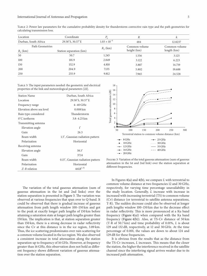
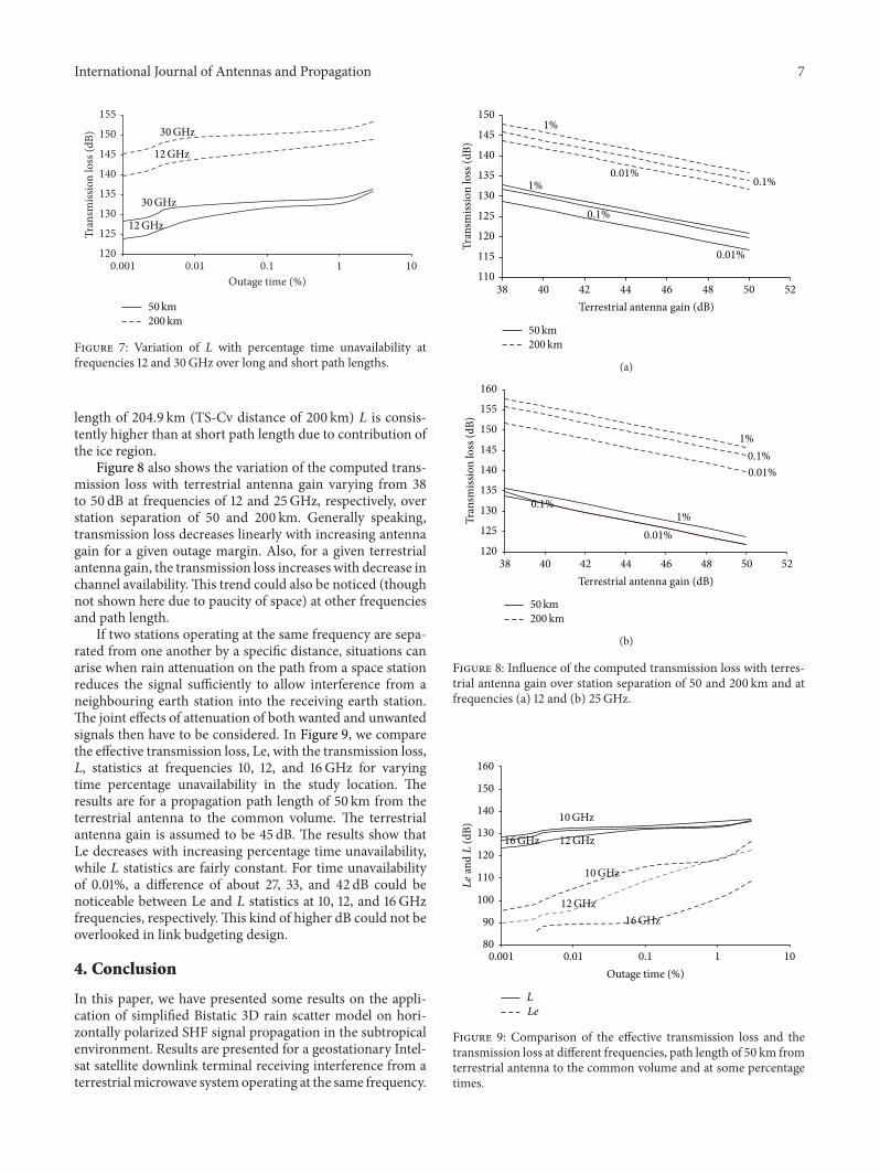

International Journal of
AerospaceEngineeringHindawi Publishing Corporationhttpwwwhindawicom Volume 2014
RoboticsJournal of
Hindawi Publishing Corporationhttpwwwhindawicom Volume 2014
Hindawi Publishing Corporationhttpwwwhindawicom Volume 2014
Active and Passive Electronic Components
Control Scienceand Engineering
Journal of
Hindawi Publishing Corporationhttpwwwhindawicom Volume 2014
International Journal of
RotatingMachinery
Hindawi Publishing Corporationhttpwwwhindawicom Volume 2014
Hindawi Publishing Corporation httpwwwhindawicom
Journal ofEngineeringVolume 2014
Submit your manuscripts athttpwwwhindawicom
VLSI Design
Hindawi Publishing Corporationhttpwwwhindawicom Volume 2014
Hindawi Publishing Corporationhttpwwwhindawicom Volume 2014
Shock and Vibration
Hindawi Publishing Corporationhttpwwwhindawicom Volume 2014
Civil EngineeringAdvances in
Acoustics and VibrationAdvances in
Hindawi Publishing Corporationhttpwwwhindawicom Volume 2014
Hindawi Publishing Corporationhttpwwwhindawicom Volume 2014
Electrical and Computer Engineering
Journal of
Advances inOptoElectronics
Hindawi Publishing Corporation httpwwwhindawicom
Volume 2014
The Scientific World JournalHindawi Publishing Corporation httpwwwhindawicom Volume 2014
SensorsJournal of
Hindawi Publishing Corporationhttpwwwhindawicom Volume 2014
Modelling amp Simulation in EngineeringHindawi Publishing Corporation httpwwwhindawicom Volume 2014
Hindawi Publishing Corporationhttpwwwhindawicom Volume 2014
Chemical EngineeringInternational Journal of Antennas and
Propagation
International Journal of
Hindawi Publishing Corporationhttpwwwhindawicom Volume 2014
Hindawi Publishing Corporationhttpwwwhindawicom Volume 2014
Navigation and Observation
International Journal of
Hindawi Publishing Corporationhttpwwwhindawicom Volume 2014
DistributedSensor Networks
International Journal of