research article analytical evaluation of reinforced
TRANSCRIPT
Research ArticleAnalytical Evaluation of Reinforced Concrete Pier andCast-in-Steel-Shell Pile Connection Behavior consideringSteel-Concrete Interface
Jiho Moon1 Dawn E Lehman2 Charles W Roeder2 Hak-Eun Lee3 and Tae-Hyung Lee4
1New Transportation Research Center Korea Railroad Research Institute (KRRI) Uiwang-si Gyeonggi-do 16105 Republic of Korea2Department of Civil amp Environmental Engineering University of Washington Seattle WA 98195 USA3Department of Architectural Civil amp Environmental Engineering Korea University Seoul 02841 Republic of Korea4Department of Civil Engineering Konkuk University Seoul 05029 Republic of Korea
Correspondence should be addressed to Tae-Hyung Lee thleekonkukackr
Received 25 August 2015 Revised 25 December 2015 Accepted 27 December 2015
Academic Editor Kaveh Edalati
Copyright copy 2016 Jiho Moon et al This is an open access article distributed under the Creative Commons Attribution Licensewhich permits unrestricted use distribution and reproduction in any medium provided the original work is properly cited
The seismic design of bridges may require a large-diameter deep pile foundation such as a cast-in-steel-shell (CISS) pile where areinforced concrete (RC) member is cast in a steel casing In practice the steel casing is not considered in the structural design andthe pile is assumed to be an RC member It is partially attributed to the difficulties in evaluation of composite action of a CISS pileHowever by considering benefits provided by composite action of the infilled concrete and the steel casing both the cost and sizeof CISS pile can be reduced In this study the structural behavior of the RC pier and the CISS pile connection is simulated by usingan advanced 3D finite element (FE) method where the interface between the steel and concrete is also modeled Firstly the FEmodel is verifiedThen the parametric study is conductedThe analysis results suggest that the embedment length and the frictioncoefficient between the steel casing and the infilled concrete affect the structural behavior of the RC pier Finally the minimumembedment length with reference to the AASHTO design guideline is suggested considering the composite action of the CISS pile
1 Introduction
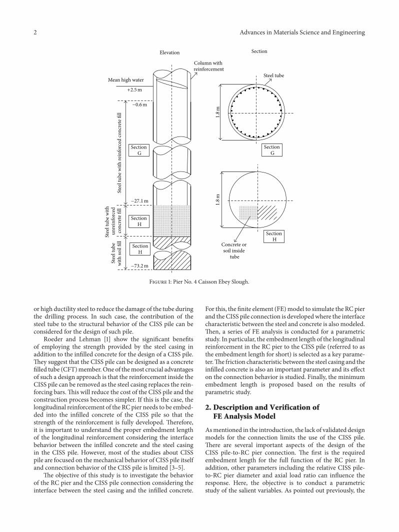
Cast-in-steel-shell (CISS) piles are driven pipe piles filledwithcast-in-place reinforced concrete (RC) with longitudinal andtransverse reinforcing bars CISS piles are frequently used fora bridge foundationwhen the construction site consists of softor liquefiable soil or when a large lateral soil deformation dueto seismic loading is expected The construction sequencesof a CISS pile are as follows (1) a steel casing is driven(2) soil inside the steel casing is removed (3) a mesh oflongitudinal and transverse reinforcing bars is placed and (4)the concrete is poured and cured These elements can exceed2m in diameter and more than 70m in length An exampleof the CISS pile is Pier No 4 of the Ebey Slough project inWashington State as shown in Figure 1 In this case the steelcasing is 18m in diameter and 25mm thick The CISS pileextends approximately 725m below the base of the bridgepier The CISS pile is reinforced with 32 14 longitudinal bars
(the diameter of 14 reinforcing bar is 43mm) and heavyspiral transverse reinforcement
A CISS pile is typically designed as an RCmember ignor-ing the strength of the steel casing and the composite actionbetween the steel casing and the infilled concrete [1] Thecurrent AASHTO LRFD bridge design specification [2] pro-vides the design details of such piles but does not consider thestrength of the steel casingThere are a few reasons for ignor-ing the strength of the steel casing in the CISS pile designFirstly the composite action of the steel casing and the infilledconcrete is unclear since the friction coefficient may decreasewith increasing the dirt or other debris in the steel casingSecondly the steel casing is not properly protected fromrusting and it may lead to the reduction of the steel cross-sectional area Thirdly the steel casing may be damagedduring the drilling process which also leads to the reductionof the steel cross-sectional area These problems might besolved by using the weathering steel to prevent the corrosion
Hindawi Publishing CorporationAdvances in Materials Science and EngineeringVolume 2016 Article ID 4159619 14 pageshttpdxdoiorg10115520164159619
2 Advances in Materials Science and Engineering
Stee
l tub
e with
rein
forc
ed co
ncre
te fi
ll
Stee
l tub
e with
un
rein
forc
ed
conc
rete
fill
Stee
l tub
e w
ith so
il fil
l
Mean high water
Column with reinforcement
Elevation Section
Section G
Section H
Section H
Section G
Section H
Steel tube
Concrete or soil inside
tube
+25m
minus271m
minus732m
minus06m
18
m18
m
Figure 1 Pier No 4 Caisson Ebey Slough
or high ductility steel to reduce the damage of the tube duringthe drilling process In such case the contribution of thesteel tube to the structural behavior of the CISS pile can beconsidered for the design of such pile
Roeder and Lehman [1] show the significant benefitsof employing the strength provided by the steel casing inaddition to the infilled concrete for the design of a CISS pileThey suggest that the CISS pile can be designed as a concretefilled tube (CFT)memberOne of themost crucial advantagesof such a design approach is that the reinforcement inside theCISS pile can be removed as the steel casing replaces the rein-forcing barsThis will reduce the cost of the CISS pile and theconstruction process becomes simpler If this is the case thelongitudinal reinforcement of the RC pier needs to be embed-ded into the infilled concrete of the CISS pile so that thestrength of the reinforcement is fully developed Thereforeit is important to understand the proper embedment lengthof the longitudinal reinforcement considering the interfacebehavior between the infilled concrete and the steel casingin the CISS pile However most of the studies about CISSpile are focused on themechanical behavior of CISS pile itselfand connection behavior of the CISS pile is limited [3ndash5]
The objective of this study is to investigate the behaviorof the RC pier and the CISS pile connection considering theinterface between the steel casing and the infilled concrete
For this the finite element (FE)model to simulate the RC pierand the CISS pile connection is developedwhere the interfacecharacteristic between the steel and concrete is also modeledThen a series of FE analysis is conducted for a parametricstudy In particular the embedment length of the longitudinalreinforcement in the RC pier to the CISS pile (referred to asthe embedment length for short) is selected as a key parame-terThe friction characteristic between the steel casing and theinfilled concrete is also an important parameter and its effecton the connection behavior is studied Finally the minimumembedment length is proposed based on the results ofparametric study
2 Description and Verification ofFE Analysis Model
Asmentioned in the introduction the lack of validated designmodels for the connection limits the use of the CISS pileThere are several important aspects of the design of theCISS pile-to-RC pier connection The first is the requiredembedment length for the full function of the RC pier Inaddition other parameters including the relative CISS pile-to-RC pier diameter and axial load ratio can influence theresponse Here the objective is to conduct a parametricstudy of the salient variables As pointed out previously the
Advances in Materials Science and Engineering 3
Basic analysis model
Axial load
Lateral load
Cap beam (reinforcement is not shown)
CISS pile foundation
RC pier
PH
(a) (b)
L1
L2le
D2
D1
Figure 2 Geometry of (a) CISS pile-to-reinforced concrete pier connection and (b) basic analytical model Note all shear reinforcement isnot shown
Symmetric BCabout 2-3 plane
Fixed BC
1
23
123
Step 1 Uniform axial load
Step 2 Lateral
displacement
ConcreteSolid element
Steel casingShell element
InterfaceGAP element
ReinforcementTruss element
Figure 3 Boundary condition loading and element used in the finite element model
study about the CISS pile-to-RC pier connection is limitedTherefore a validated FE modeling approach is developed tostudy this connectionThenonlinear FE analysis is performedby using general purpose FE analysis package ABAQUS[7] First the model is validated using prior experimentalresults on the concrete filled tube (CFT) components andRC components subject to combined loading The validatedmodel is used to conduct a parametric study which is thenused to evaluate design expression for this connection
21 Description of FE Analysis Model The typical CISS pile-to-RC pier connection is illustrated in Figure 2 where119863
1and
1198632are the diameters and 119871
1and 119871
2are the lengths of the
RC pier and CISS pile respectively and 119897119890is the embedment
length 119875 and119867 are the axial and the lateral forces that act onthe RC pier Figure 3 shows the FE model of the CISS pile-to-RC pier connection used in this study For efficient modeling
only half of the system is modeled by taking advantage ofthe symmetry This approach can reduce the computationaltime The infilled concrete is modeled using 8-node solidelements with reduced integration point and the steel cas-ing is modeled using 4-node shell elements with reducedintegration point At each nodal point GAP elements areused to simulate the interface between the infilled concreteand the steel casing The GAP element allows for two nodesto be in contact (gap closed) or separated (gap open) withrespect to a particular direction and a separation condition[7] Thus infinite stiffness in compression and no stiffnessin tension condition can be simulated by using the GAPelement This modeling approach provides three distinctadvantages Firstly the relative movement (slip) between thesteel casing and the infilled concrete can be modeled directlySecondly the GAP element can simulate Poissonrsquos effect ofthe concrete in compression providing confinement stress
4 Advances in Materials Science and Engineering
to infilled concrete Therefore confining effects are modeleddirectly and an empirical model of the compressive stress-strain relationship of the confined concrete is not necessary[8] Thirdly shear stresses between the steel casing andinfilled concrete are modeled by friction which is specifiedby a friction coefficient defined in GAP elements The trusselements are used to model the reinforcing bars where thetruss element has 2 nodes with axial displacement degree offreedom and 1 integration point at the center and they areembedded into the concrete by using EMBEDED option inABAQUS [7] This modeling approach to the CISS pile ispreviously verified by comparing with experimental resultsunder various loading and boundary conditions [8 9]
Analysis of the CISS pile includes many nonlinearresponses such as concrete cracking and contact problemsThus to ensure the convergence of the solution STABILIZEoption in ABAQUS [7] is used in this study STABILIZEoption provides an automatic mechanism for stabilizingunstable quasi-static problems through the automatic addi-tion of volume-proportional damping to the model [7]
The bottom of the analysis model is fixed against rotationand translation as shown in Figure 3 The translation indirection 1 is restrained for the middle plane to simulate thesymmetric boundary about 2-3 plane as shown in Figure 3 Avertical pressure is applied at the top of the model to simulatethe axial load in the first loading step Then a monotonicallyincreasing lateral load is applied using a displacement controloption as shown in Figure 3
As mentioned earlier a CISS pile can exceed more than70m in length Thus the length of the CISS pile simulatedin the analytical model should be appropriately selected toensure efficiency and accuracy In this study the optimallength of the CISS pile is selected such that it is long enoughto minimize the end effect due to the boundary conditionwhile it is short enough tominimize the number of degrees offreedom of the modelThe selected length of the FE model ofthe CISS pile is twice the diameter of the CISS pile accordingto a parametric study
Figure 4 shows the material models used in this studyThe uniaxial compressive and tensile behaviors of the plainconcrete are modeled using the expressions proposed bySaenz [10] and Hsu and Mo [11] respectively as shown inFigure 4(a) where Youngrsquos modulus of the concrete 119864
119888 is
estimated as 4700radic1198911015840119888(MPa) according to ACI design code
[12] 1205761015840119888in Figure 4(a) is set as 0003 119891
119888119903of the concrete is
defined as 031radic1198911015840119888(MPa) based on the results of Hsu andMo
[11] The elastic response is assumed up to 051198911015840119888 To simulate
inelastic behavior of the concrete under a general 3D stressstate the concrete damaged plasticity model in ABAQUS [7]is adopted A value of 20∘ for the dilation angle 120595 is adoptedfrom the previous research for the CFT modeling conductedbyMoon et al [8] and 31∘ for the RC pier is determined fromthe comparison with the previous RC column test conductedby Pang et al [13]
The average stress-strain relationship of a reinforcingbar embedded in concrete is different from that of a barereinforcing bar [11] The primary difference is the lowereffective yield stress of reinforcing bar 119891
119910119903 In this study the
average stress-strain relationship of an embedded reinforcingbar proposed by Hsu and Mo [11] is adopted as shown inFigure 4(b) Youngrsquos modulus of the reinforcing bar 119864
119903 is
assumed to be 200GPa In Figure 41198911015840119910119903(the reduced effective
yield stress of the reinforcing bar) and 1198641015840119901119903are the function of
the reinforcement ratio 120588 and the details of calculation ofthese values can be found in [11]
For the steel casing a trilinear stress-strain relationshipis used with an isotropic hardening plasticity rule Youngrsquosmodulus of the steel 119864
119904 is approximated to 200GPa and
Poissonrsquos ratio of the steel 120592119904 is set as 03 The plastic plateau
terminates when strain of the steel 120576119904 is equal to 10 times
the yield strain of the steel (10120576119904119910) and stress increases up to
ultimate strength of the steel 119891119906 which is achieved when the
ultimate strain of the steel 120576119904119906 is 01 as shown in Figure 4(c)
22 Verification of FE Analysis Model The test results fromLow and Moehle [6] are used to verify the accuracy ofthe model for well and poorly embedded reinforcementFigure 5(a) shows the dimensions of the test specimenwhere the column section is 127mm by 165mm and thelongitudinal reinforcement consisted of 2 and 3 bars (Thediameters of 2 and 3 bars are 635mm and 9525mm resp)The reinforcing bars are embedded to a depth of 1178mmas shown in Figure 5(a) In addition to the experimentalresults analytical results by Luccioni et al [14] are used forverification Luccioni et al [14] conduct a structural analysisfor the model shown in Figure 5(a) to verify their bond-slipmodel for reinforcing bar Then they conduct a parametricstudy to investigate the effect of the embedment length ofthe longitudinal reinforcing bar Both the analytical results ofLuccioni et al [14] and the experimental results fromLow andMoehle [6] are used to validate the FE model developed inthis study
Figure 5(b) shows the column-foundation designs stud-ied in Luccionirsquos study The models have embedment lengthsof approximately 19119889
1198873(1778mm) 8119889
1198873(762mm) and 3119889
1198873
(254mm) where 1198891198873
is the diameter of a 3 bar The resultsof Low andMoehle [6] Luccioni et al [14] and the proposedmodel in this study are compared in Figure 6(a)The stiffnessand peak strength are very similar for all three models Forthe shorter embedment lengths (119897
119890= 762 and 254mm) as
shown in Figures 6(b) and 6(c) postpeak behaviors of thetwo simulated analyses are slightly differentHowever neitherhas been verified with experimental results and slight differ-ences are expected with different approaches for the interfacemodeling between reinforcing bar and concrete For thecomparison of the peak strength the difference between theanalysis models and the results of Luccioni et al [14] are 5and 1 for the models having the embedment length of 8119889
1198873
and 31198891198873 respectivelyThus the proposed FEmodel is appro-
priate to simulate the behavior of the CISS pile-to-RC pierconnection
3 Parametric Study
31 Models for Parametric Study A parametric study isperformed to evaluate the effect of salient design parameters
Advances in Materials Science and Engineering 5
fc
f998400c
05f998400c
Ec
120576cr
fcr
120576c120576998400c
(a)
Embedded reinforcing bar
Bare reinforcing bar
Smeared reinforcing bar strain 120576r
Smea
red
rein
forc
ing
bar s
tressfr
120576998400r
Er
E998400prfyr
f998400yr
(b)
Stee
l stre
ssfs
Steel strain 120576s
fu
fy
Es
10120576sy 120576su = 01
(c)
Figure 4 Material models for (a) plain concrete (b) reinforcing bar and (c) steel casing
y
x
Lateral load
1650
mm
1270mm
445 kN
1778
mm
5144
mm
2bar
3bar
(a)
YX
Z
le = 254mm (1 in)le = 762mm (3 in)le = 1778mm (7 in)
(b)
Figure 5 Verification model (a) test specimen of Low and Moehle [6] and (b) verification model for different embedment depths ofreinforcing bars
6 Advances in Materials Science and Engineering
5 10 15 20 25 300Lateral displacement (mm)
0
10
20
30
Late
ral l
oad
(kN
)
le = 1778mm Low and Moehle [6]le = 1778mm Luccioni et al [14]le = 1778mm FEM
(a)
0
10
20
30
Late
ral l
oad
(kN
)
25 50 75 10000Lateral displacement (mm)
le = 762 mm Luccioni et al [14]le = 762mm FEM
(b)
25 50 75 10000Lateral displacement (mm)
0
10
20
30
Late
ral l
oad
(kN
)
le = 254mm Luccioni et al [14]le = 254mm FEM
(c)
Figure 6 Verification results (a) 119897119890= 1778mm (b) 119897
119890= 762mm and (c) 119897
119890= 254mm
Table 1 Properties of the reference model
1198631(mm) 119863
111986321198632119905 119871
1119863111987121198632119897119890119897119889AASHTO 119891
1015840
119888(MPa) 119891
119910(MPa) 119891
119910119903(MPa) 119875119875
119900RC FC1372 09 100 4 2 211 345 3445 4134 01 047
on the CISS pile-to-RC pier connection behavior The designdetails of the base model are presented in both of Table 1 andFigure 7 The length of the RC pier 119871
1 was set as 4119863
1 which
was the marginal length for a flexural column The optimallength of the CISS pile 119871
2 is determined as 2119863
2according to
the criteria mentioned earlier The yield stresses of the steelcasing and reinforcing bar (119891
119910and 119891
119910119903 resp) are taken as
3445MPa and 4134MPa respectively The ultimate stress ofthe steel casing119891
119906 is 4823MPaThe compressive strength of
concrete 1198911015840119888 is 345MPa 119875
119900RC shown in Table 1 is the squash
Advances in Materials Science and Engineering 7
RC pier section
H
Longitudinal L1=54864
mm
L2=3048
mm
P = 0 01 and 02PoRC
137
m
le
D2
05D1
05D1
D1 = 1372mm
except plastic hinge region (10bar)Shear reinforcement 6bar
reinforcement 10bar
Figure 7 Analytical model for parametric study
Table 2 Ranges of the values of each study parameter
119863111986321198632119905 119897
119890119897119889AASHTO 119875119875
119900RC FC08ndash10 80ndash120 070ndash211 00ndash02 005ndash06
load of the RC pier and it is defined as 0851198911015840119888119860119888+ 119891119910119887119860119887119905
according to ACI design code [12] where 119860119888is the cross-
sectional area of the concrete and 119891119910119887
and 119860119887119905are the yield
stress and the total area of the reinforcing bar respectively InTable 1 119897
119890is the embedment length of the reinforcing bar into
the CISS pile The axial load ratio 119875119875119900RC was set as 01 for
the base modelThe RC pier is reinforced with 32 10 longitudinal
reinforcing bars (the diameter of 10 reinforcing bar is3226mm) as shown in Figure 7 resulting in a longitudinalreinforcement ratio of 18 The spiral reinforcement variedalong the length of the pierOutside of the plastic hinge region(outside of plusmn05119863
1from the interface between the RC pier
and the CISS pile refer to Figure 7) 6 spiral reinforcementsspaced at 127mm are used The diameter of 6 reinforcingbar is 1905mm It results in transverse reinforcement ratioof 033 Within the possible plastic hinge region 10spiral spaced at 127mm is used to meet the requirement ofAASHTOLRFDdesign code [2] for theminimum shear rein-forcement ratio in the plastic hinge region where the trans-verse reinforcement ratio is equal to 094 for this region
The parametric study is conducted by using the basemodel shown in Table 1 The range of the value of eachparameter is given in Table 2 The parameters are theembedment length (119897
119890) the friction coefficient between the
infilled concrete and the steel casing the diameter to wallthickness ratio of the steel casing (119863
2119905 ratio) the axial load
ratio and the diameter ratio between the RC pier and theCISS pile (119863
11198632)The embedment 119897
119890 ranges from07 to 211
Four different values (005 025 047 and 06) are used for thefriction coefficient Three different 119863
2119905 ratios (80 100 and
120) are used for the steel casing Three different axial loadratios 119875119875
119900RC (0 01 and 02) are selected Three differentvalues of 119863
11198632(08 09 and 10) are used Total 40 models
are analyzed for a parametric studyThe primary parameter is the embedment length 119897
119890 The
value of 119897119890is normalized by the development length specified
in AASHTO LRFD design code [2] for deformed bar intension 119897
119889AASHTO is defined as
119897119889AASHTO = 125
119860119887119891119910119887
radic1198911015840119888
(1)
for a 10 bar or smaller bar where 119860119887is the area of the
reinforcing bar It should be noted that 119897119889AASHTO must be
properly modified using the factors specified in AASHTOLRFD design code [2] for various conditions and locations ofreinforcing bars The details of the modification factors canbe found in AASHTO LRFD design code [2] The axial loadis applied first Then the lateral displacement at the top ofthe RC pier is monotonically increased up to 254mm whichis approximately 46 total drift of the RC pier This value issufficient to develop full plastic action in the systems
32 Results of Parametric Study Figures 8(a) and 8(b) showthe crack pattern and failure mechanism for the analysismodels with 119897
119890119897119889AASHTO = 07 and 211 respectively It is
noted that the distribution of themaximumequivalent tensileplastic strain of the concrete shown in Figure 8 representsthe cracking in the concrete [7] Let us consider the model
8 Advances in Materials Science and Engineering
M
Overturning moment
Tensile cracking below reinforcement
(max principle PE = 0134)
Slip between the tube and concrete infill(measure point)
CISSpile
RC pier
leldAASHTO = 070
PPoRC = 01 PE max principalSNEG (fraction = minus10)
(Avg 75)+1335e minus 01
+4000e minus 02
+3200e minus 02
+2400e minus 02
+1600e minus 02
+8000e minus 03
+0000e + 00
(a)
M
Tensile cracking(max principle
PE = 004)
Spalling
CISSpile
RC pier
leldAASHTO = 211
PPoRC = 01
+4000e minus 02
+3200e minus 02
+2400e minus 02
+1600e minus 02
+8000e minus 03
+0000e + 00
PE max principalSNEG (fraction = minus10)
(Avg 75)
(b)
Figure 8 Crack pattern and failure mechanism for different embedment lengths (a) 119897119890= 070119897
119889AASHTO and (b) 119897119890= 211119897
119889AASHTO
with 119897119890119897119889AASHTO = 07 first Figure 8(a) shows that a single
predominant crack forms in the steel casing portion at theend of the embedded reinforcement Following the openingof the crack the reinforcement in the RC pier is pulled outfrom the concrete and the RC pier is separated from the CISSpile This damage pattern resulted in an excessive rotation ofRC pier This is an undesirable response mode since it limitsthe inelastic deformation capacity of the system On the otherhand a different failuremechanismoccurs for deeper embed-ment length cases The tension side is cracked while thespalling of the cover concrete is observed on the compressionside and a significant inelastic action is sustained at the base ofRC pier for 119897
119890119897119889AASHTO = 211 case as shown in Figure 8(b)
This is a desirable inelastic response mechanism for whicha stable plastic hinge forms including cracking and plasticaction in the longitudinal reinforcement in tension andcompression side
Figure 9 shows analytical results for four different embed-ment lengths of the reinforcing bar The embedment lengthswere normalized by 119897
119889AASHTO In Figures 9(a) and 9(b) twodifferent drift measures were used ldquoTotal driftrdquo indicates therelative rotation of the RC pier to the top of CISS pile asshown in Figures 10(a) and 10(b) ldquoPier driftrdquo in this studyis defined as the total drift minus the rigid body rotation ofthe RC pier due to the slip between the steel casing and theinfilled concrete as shown in Figure 10(c)Thus the pier driftindicates the pure flexural rotation of the RC pier It shouldbe noted that the difference between the total and the pierdrift represents the rigid body rotation of the RC pier due to arelative slip between the steel casing and the infilled concreteThe119910-axis in Figures 9(a) and 9(b) denotes themoment at thebase of the RC pier119872 normalized by the nominal momentstrength of the RC pier 119872
119899 obtained from general strain
compatibility method specified in ACI design code [12]
When 119897119890is larger than 119897
119889AASHTO the ultimate moment atthe base was 6 larger than 119872
119899 as shown in Figures 9(a)
and 9(b) indicating the plastic action in the RC pier Therelative slip between the steel casing and the infilled concreteismeasured at the end of tension side of the CISS pile (refer toFigure 8)When embedment length is 14119897
119889AASHTO the slip isapproximately 0005119863
1(69mm) at 3 total drift as shown
in Figure 9(c) The slip increased as the embedment lengthdecreases In addition for 119897
119890119897119889AASHTO = 07 the moment
demand of the RC pier does not reach 119872119899 Furthermore
the comparison of Figures 9(a) and 9(b) reveals that mostof the drift for the analysis model with shorter embedmentlengths results from the rotation of the connectionThis resultsuggests that the excessive slip between the infilled concreteand the steel casing which is generated by the overturningdemands of RC pier compromises the response of the systemand it can be seen that the embedment length has a significantimpact on the performance of the system
Figure 11 shows selected results of the parametric studywhen 119897
119889AASHTO = 07 that is the embedment length issmaller than the development length specified in AASHTOLRFD [2] design code Figures 11(a) 11(b) 11(c) and 11(d)show the effects of the119863
2119905 ratio the friction coefficient (FC
in the figure) the axial load ratio 119875119875119900RC and 11986311198632 ratio
respectively It should be noted that the dimension1198631is fixed
when11986311198632is varied and the drift in 119909-axis is corrected for
the translation of the CISS pile only (ie 119909-axis representsthe total drift) These variables are chosen for the followingreasons (1) the 119863
2119905 ratio is a fundamental variable which
impacts the local instability of the steel tube and the strengthof a CISS pile (2) it is assumed that the friction coefficientbetween the steel casing and infilled concrete varies withinthe range of 005 and 06 According to Baltay and Gjelsvik[15] the friction coefficient between the steel and the concrete
Advances in Materials Science and Engineering 9
1 2 3 40Total drift ()
leldAASHTO = 070
leldAASHTO = 101leldAASHTO = 141
leldAASHTO = 211
MM
n
00
02
04
06
08
10
12
14D2t = 100 PPoRC = 01 FC = 047 D1D2 = 09
(a)
1 2 3 40Pier drift ()
leldAASHTO = 070
leldAASHTO = 101leldAASHTO = 141
leldAASHTO = 211MM
n
00
02
04
06
08
10
12
14D2t = 100 PPoRC = 01 FC = 047 D1D2 = 09
(b)
1 2 3 40Total drift ()
leldAASHTO = 070
leldAASHTO = 101leldAASHTO = 141
leldAASHTO = 211
00
05
10
15
20
25
Slip
D1
()
D2t = 100 PPoRC = 01 FC = 047 D1D2 = 09
(c)
Figure 9 Effect of 119897119890 (a)119872119872
119899vs total drift (b)119872119872
119899vs pier drift and (c) Slip119863
1vs total drift
varies from 03 to 06 and the mean value is equal to 047The variation in the friction coefficient represents the qualityof the interface reflecting the effect of dirt or other debrisin a steel casing For example the friction coefficient maydecrease with increasing the dirt or other debris in the steelcasing In this study a small friction coefficient such as 005is adopted Such conservative value (FC = 005) is adoptedfor the analysis to simulate the extreme case due to lack ofexperimental data for the friction coefficient of the CISS pile
(3) the variation in the axial load affects the flexural strengthof RC pierThe practical range of the axial load ratio (119875119875
119900RCranges from0 to 02) is investigated and (4) the diameter ratiois investigated as a primary design parameter to consider itsimpact on the response
Figure 11 shows that the strength is increased with (1) adecrease in the 119863
2119905 ratio of the CISS pile (2) a decrease
in the 11986311198632ratio (08 lt 119863
11198632lt 1) (3) an increase in
friction coefficient between the steel casing and the infilled
10 Advances in Materials Science and Engineering
CISS pile
RC pier
H
P
Δtotal
ΔCISS
(a)
Vertical displacementdue to bending
a
b
Vertical displacementdue to bending
Δro1
Total drift () = (
120579ro1
120579ro1
Δtotal minus ΔCISS minus Δro1)L1 times 100
(b)
SlipSlip
a b
c
d
Δro2
Pier drift () = (
120579ro2
120579ro2
Δtotal minus ΔCISS minus Δro2)L1 times 100
(c)
Figure 10 Definition of total and pier drift (a) deflection of CISS pile and RC pier (b) definition of total drift and (c) definition of pier drift
concrete and (4) an increase in the axial load ratio 119875119875119900RC
up to a value of 02 However although some of these modelsreached the nominal moment strength119872
119899 they still resulted
in a pull-out failure which is not desirable An increase inthe axial load ratio and the friction coefficient provides theadditional resistance to a pull-out failure for the analysismodel shown in Figure 11 and it results in a higher strengthwhen the embedment depth is not sufficient
Figure 12 shows the results of parametric study for thelonger embedment length (119897
119890119897119889AASHTO = 141) For all
analysis results cracking in tension and the spalling incompression side at the base of RC pier are observed andthe effects of 119863
2119905 ratio friction coefficient and 119863
11198632ratio
are negligible since the strength of the connection is enoughto develop the plastic hinge as shown in Figures 12(a) 12(b)and 12(d) Furthermore it can be found that increase in theaxial load and decrease in 119863
11198632ratio result in increase in
stiffness as shown in Figures 12(c) and 12(d)From Figure 12(c) a strength degradation is observed
for the analysis model with 119875119875119900RC = 02 Generally a
brittle failure occurs when the applied axial load exceedsthe axial load of the balanced point in a 119875-119872 interactioncurve for a reinforced concrete column because the concretecrushing occurs before the yielding of the reinforcing barThesame failure mode is observed for the analysis model having119875119875119900RC = 02A key aspect of adequate development length is the ability
to develop strains beyond the yield strain in the anchoredbar This is studied for each of the models Figure 13 showsthe relationship between the axial strain in compression (ortension) reinforcing bar at 3 drift and 119897
119890119897119889AASHTO It is
noted that the axial strain in reinforcing bar is obtained atthe interface between the CISS pile and RC column When119897119890119897119889AASHTO is less than 1 the majority of the models did
not reach strains that exceed the yield strain 120576119910 as shown
in Figures 13(a) and 13(b) For the analysis models with119897119890119897119889AASHTO = 101 there is a variation in the achieved axial
strain of the reinforcing bar Some of the analysis results donot reach to yield strain In particular this is true for modelswith very low friction coefficient (FC = 005) Furthermorewhen 119897
119890119897119889AASHTO is larger than 15 strain in the tension
reinforcing bar approximately reaches to 5120576119910 as shown in
Figure 13(b) When 11986311198632is equal to 1 (ie the diameter
of the CISS pile and RC pier is the same) the strain incompression reinforcing bar is relatively high compared withthe other cases This is because compression reinforcing baris slightly buckled due to lack of sufficient concrete areaat interface between the CISS pile and RC pier Taken aswhole the analysis results show that 119897
119890119897119889AASHTO should be
larger than approximately 15 to achieve considerable inelasticdeformation in reinforcing bar
Figure 14 represents variation in the moment capacity ofthe connection with embedment length of reinforcing barFor values of 119897
119890119897119889AASHTO = 070 and 101 some of the
analysis results do not achieve sufficient moment capacity ofthe connection In particular this is noted for the modelswith low friction coefficient values as shown in Figure 14The analysis results with the friction coefficient of 005 givelow bound for the moment capacity of the CISS pile-to-RC pier connection These results show that 119897
119890119897119889AASHTO
should be larger than approximately 125 Thus a minimumvalue of 119897
119890119897119889AASHTO = 15 is recommended to develop
the full strength of the CISS pile-to-RC pier connectionand considerable inelastic deformation in reinforcing bar atthe same time However this recommendation is based onan analytical study only without experimental results Theadditional experimental research is needed to develop robustdesign equation for the minimum embedment length of thepier longitudinal reinforcement into the CISS pile
Advances in Materials Science and Engineering 11
1 2 3 4 50Total drift ()
leldAASHTO = 070 PPoRC = 01
FC = 047 D1D2 = 09
00
02
04
06
08
10
12
14
MM
n
D2t = 80
D2t = 100D2t = 120
(a)
FC = 005FC = 025
FC = 047FC = 060
leldAASHTO = 070 D2t = 100
D1D2 = 09PPoRC = 01
00
02
04
06
08
10
12
14
MM
n
1 2 3 4 50Total drift ()
(b)
FC = 047 D1D2 = 09
leldAASHTO = 070 D2t = 100
PPoRC = 0
PPoRC = 01
PPoRC = 02
00
02
04
06
08
10
12
14
MM
n
1 2 3 4 50Total drift ()
(c)
D1D2 = 09D1D2 = 08 D1D2 = 10
leldAASHTO = 070 D2t = 100
PPoRC = 01 FC = 047
00
02
04
06
08
10
12
14
MM
n
1 2 3 4 50Total drift ()
(d)
Figure 11 Impact of parameters for 119897119890119897119889AASHTO = 070 (a) effect of 1198632119905 ratio (b) effect of friction coefficient (c) effect of axial load ratio
and (d) effect of11986311198632ratio
4 Summary and Conclusions
This study presents a nonlinear FE analysis result of the CISSpile-to-RC pier connection considering the steel-concreteinterface behavior The effect of the embedment length of thereinforcing bars to the strength of the RC pier is evaluatedThe effect of the friction coefficient between the steel casingand the infilled concrete is also evaluated Depending on the
embedment length of the reinforcing bar that extends into theCISS pile two different failure mechanisms are observed Forthe short embedment lengths the pull-out failure is notedwhile a desirable plastic action at the bottom of the RC pier isgenerated when the embedment depth is sufficient
The effects of key parameters are evaluated by conductinga parametric study For a short embedment length thereis an increased likelihood of pull-out failure The effects of
12 Advances in Materials Science and Engineering
1 2 3 4 50Total drift ()
00
02
04
06
08
10
12
14
MM
nleldAASHTO = 141 PPoRC = 01
FC = 047 D1D2 = 09
D2t = 80
D2t = 100
D2t = 120
(a)
1 2 3 4 50Total drift ()
00
02
04
06
08
10
12
14
MM
nFC = 005FC = 025
FC = 047FC = 060
leldAASHTO = 141 D2t = 100
D1D2 = 09PPoRC = 01
(b)
1 2 3 4 50Total drift ()
00
02
04
06
08
10
12
14
MM
n
FC = 047 D1D2 = 09
leldAASHTO = 141 D2t = 100
PPoRC = 0
PPoRC = 01
PPoRC = 02
(c)
1 2 3 4 50Total drift ()
00
02
04
06
08
10
12
14
MM
n
D1D2 = 09D1D2 = 08 D1D2 = 10
leldAASHTO = 141 D2t = 100
PPoRC = 01 FC = 047
(d)
Figure 12 Results of parametric study (119897119890119897119889AASHTO = 141) (a) effect of 1198632119905 ratio (b) effect of friction coefficient (c) effect of axial load
ratio and (d) effect of11986311198632ratio
1198632119905 ratio friction coefficient and119863
11198632ratio are negligible
when the embedment length of reinforcing bar is sufficientFurthermore a satisfactory performance in terms of strengthstiffness and strain demand is achieved for well-anchoredmodels Based on the parametric study it is suggestedthat 119897
119890119897119889AASHTO should be larger than 15 to develop the
full strength of the CISS pile-to-RC pier connection and a
considerable inelastic deformation in reinforcing bar simul-taneously
Conflict of Interests
The authors declare that there is no conflict of interestsregarding the publication of this paper
Advances in Materials Science and Engineering 13
FC = 025
FC = 005
Compression reinforcing bar
D1D2 = 1
00 05 10 15 20 25 30leldAASHTO
Yield strain 120576y
5120576yminus0010
minus0005
0000
Stra
in at
3
tota
l drift
(a)
Tension reinforcing bar
FC = 025
FC = 005
05 10 15 20 25 3000leldAASHTO
0000
0005
0010
0015
0020
Stra
in at
3
tota
l drift
Yield strain 120576y
5120576y
(b)
Figure 13 Variation in strain of reinforcement at 35 of drift with 119897119890119897119889AASHTO (a) compression reinforcing bar and (b) tension reinforcing
bar
Analysis results
FC = 005
10 15 20 2505leldAASHTO
MnF
EMM
n
06
08
10
12
14
Figure 14 Variation in moment capacity of the connection withembedment length of reinforcement
Acknowledgments
This researchwas supported by a grant fromRampDProgramofthe Korea Railroad Research Institute Republic of Korea andby a grant (15RTRPB069124-03) from Railroad TechnologyResearch Program funded by Ministry of Land Infrastruc-ture andTransport of KoreanGovernment Also it is partiallysupported by a Korea University grant
References
[1] C W Roeder and D E Lehman ldquoInitial investigation ofreinforced concrete filled tubes for use in bridge foundationsrdquo
Report WA-RD 7762 Washington Department of Transporta-tion Olympia Wash USA 2012
[2] AASHTO AASHTO LRFD Bridge Design Specification Wash-ington DC USA 5th edition 2010
[3] P F Silva S Sritharan F Scible and M J N Priestley ldquoFull-scale test of the Alaska cast-in-place steel shell three columnbridge bentrdquo Tech Rep SSRP 9813 Alaska Department ofTransportation and Public Facilities Juneau Alaska USA 1999
[4] M Gebman S Ashford and J Restrepo ldquoInvestigation of theaxial load transfermechanism in cast-in-steel-shell pilerdquo ReportTR-0402 Department of Structural Engineering University ofCalifornia San Diego San Diego Calif USA 2004
[5] M Gebman S Ashford and J Restrepo ldquoInvestigation of theaxial load transfer through shear rings in cast-in-steel-shell ilesrdquoTech Rep TR-0502 Department of Structural EngineeringUniversity of California San Diego Calif USA 2005
[6] S S Low and J P Moehle ldquoExperimental study of reinforcedconcrete columns subjected to multi-axial cyclic loadingrdquoEERC Report 8714 Earthquake Engineering Research CenterUniversity of California Berkeley Berkeley Calif USA 1987
[7] ABAQUS ABAQUS Analysis Userrsquos Manual Version 69-2Dassault Systemes Simulia Providence RI USA 2009
[8] J Moon CW Roeder D E Lehman andH-E Lee ldquoAnalyticalmodeling of bending of circular concrete-filled steel tubesrdquoEngineering Structures vol 42 pp 349ndash361 2012
[9] J Moon D E Lehman C W Roeder and H-E Lee ldquoStrengthof circular concrete-filled tubes with and without internalreinforcement under combined loadingrdquo Journal of StructuralEngineering ASCE vol 139 no 12 Article ID 04013012 2013
[10] L P Saenz ldquoDiscussion of lsquoequation for the stress-strain curveof concretersquo by P Desai and S Krishnanrdquo ACI StructuralJournal vol 61 pp 1229ndash1235 1964
[11] T T C Hsu and Y-L MoUnifiedTheory of Concrete StructuresJohn Wiley amp Sons Hoboken NJ USA 2nd edition 2010
14 Advances in Materials Science and Engineering
[12] ACI Building Code Requirements for Structural Concrete andCommentary American Concrete Institute Farmington HillsMich USA 2011
[13] J B K Pang M O Eberhard and J F Stanton ldquoLarge-barconnection for precast bridge bents in seismic regionsrdquo Journalof Bridge Engineering vol 15 no 3 pp 231ndash239 2010
[14] B M Luccioni D E Lopez and R F Danesi ldquoBond-slip inreinforced concrete elementsrdquo Journal of Structural Engineeringvol 131 no 11 pp 1690ndash1698 2005
[15] P Baltay and A Gjelsvik ldquoCoefficient of friction for steel onconcrete at high normal stressrdquo Journal of Materials in CivilEngineering vol 2 no 1 pp 46ndash49 1990
Submit your manuscripts athttpwwwhindawicom
ScientificaHindawi Publishing Corporationhttpwwwhindawicom Volume 2014
CorrosionInternational Journal of
Hindawi Publishing Corporationhttpwwwhindawicom Volume 2014
Polymer ScienceInternational Journal of
Hindawi Publishing Corporationhttpwwwhindawicom Volume 2014
Hindawi Publishing Corporationhttpwwwhindawicom Volume 2014
CeramicsJournal of
Hindawi Publishing Corporationhttpwwwhindawicom Volume 2014
CompositesJournal of
NanoparticlesJournal of
Hindawi Publishing Corporationhttpwwwhindawicom Volume 2014
Hindawi Publishing Corporationhttpwwwhindawicom Volume 2014
International Journal of
Biomaterials
Hindawi Publishing Corporationhttpwwwhindawicom Volume 2014
NanoscienceJournal of
TextilesHindawi Publishing Corporation httpwwwhindawicom Volume 2014
Journal of
NanotechnologyHindawi Publishing Corporationhttpwwwhindawicom Volume 2014
Journal of
CrystallographyJournal of
Hindawi Publishing Corporationhttpwwwhindawicom Volume 2014
The Scientific World JournalHindawi Publishing Corporation httpwwwhindawicom Volume 2014
Hindawi Publishing Corporationhttpwwwhindawicom Volume 2014
CoatingsJournal of
Advances in
Materials Science and EngineeringHindawi Publishing Corporationhttpwwwhindawicom Volume 2014
Smart Materials Research
Hindawi Publishing Corporationhttpwwwhindawicom Volume 2014
Hindawi Publishing Corporationhttpwwwhindawicom Volume 2014
MetallurgyJournal of
Hindawi Publishing Corporationhttpwwwhindawicom Volume 2014
BioMed Research International
MaterialsJournal of
Hindawi Publishing Corporationhttpwwwhindawicom Volume 2014
Nano
materials
Hindawi Publishing Corporationhttpwwwhindawicom Volume 2014
Journal ofNanomaterials
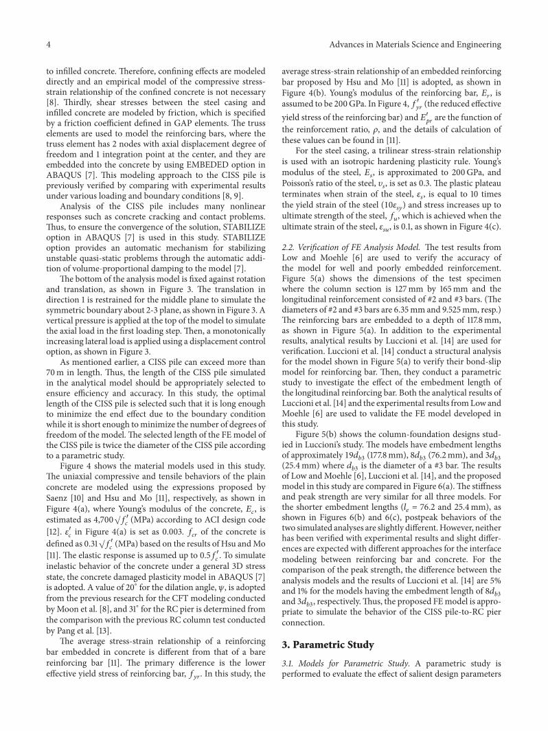
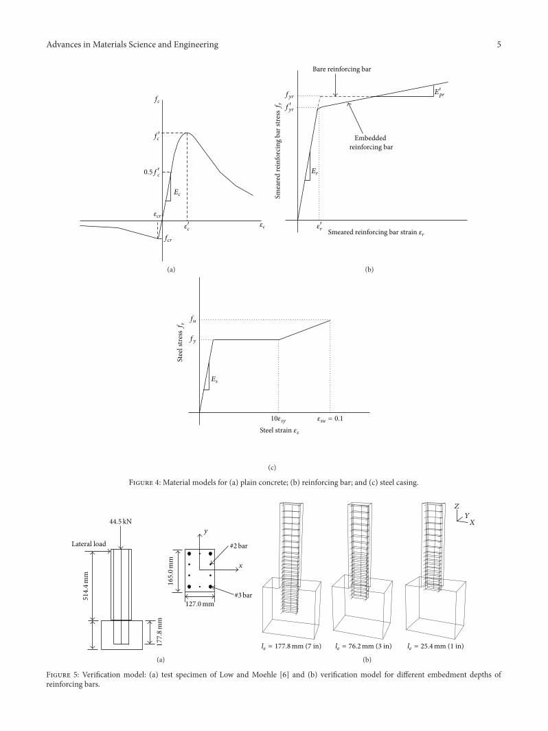
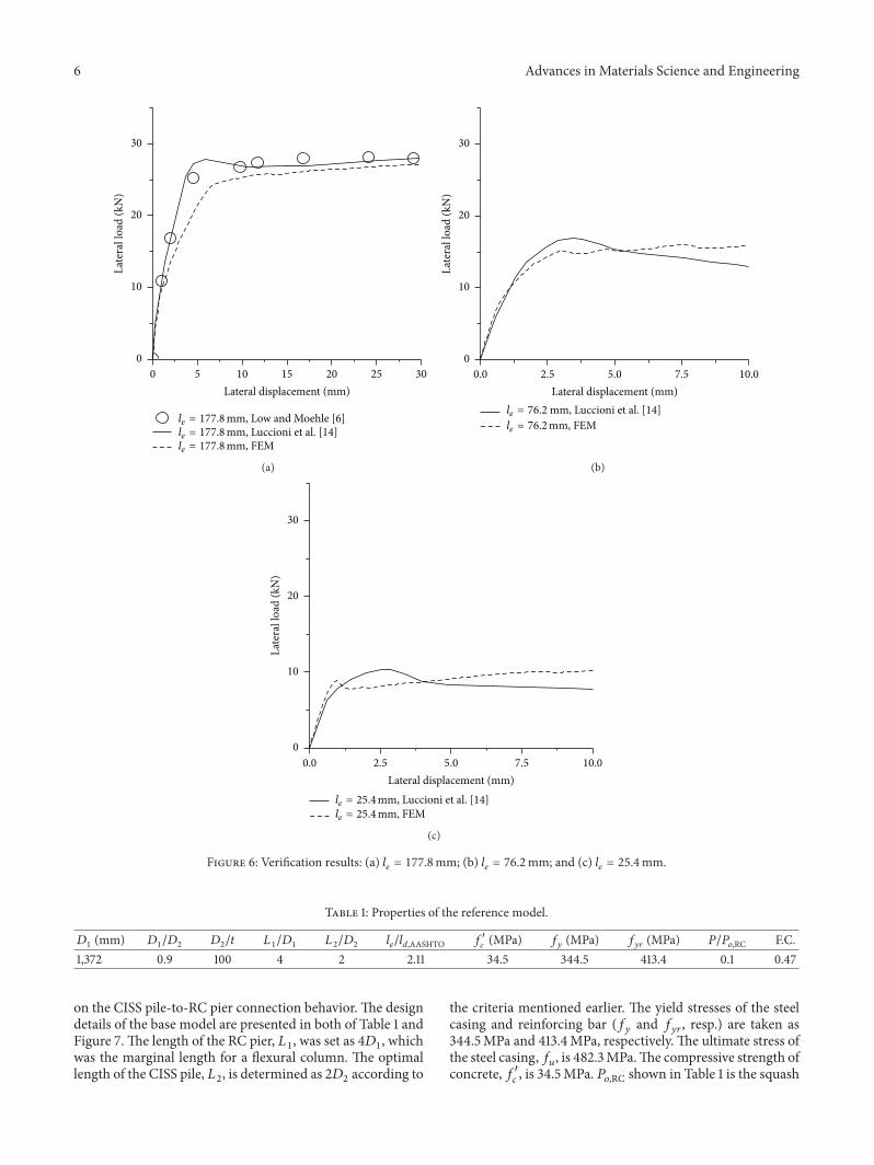
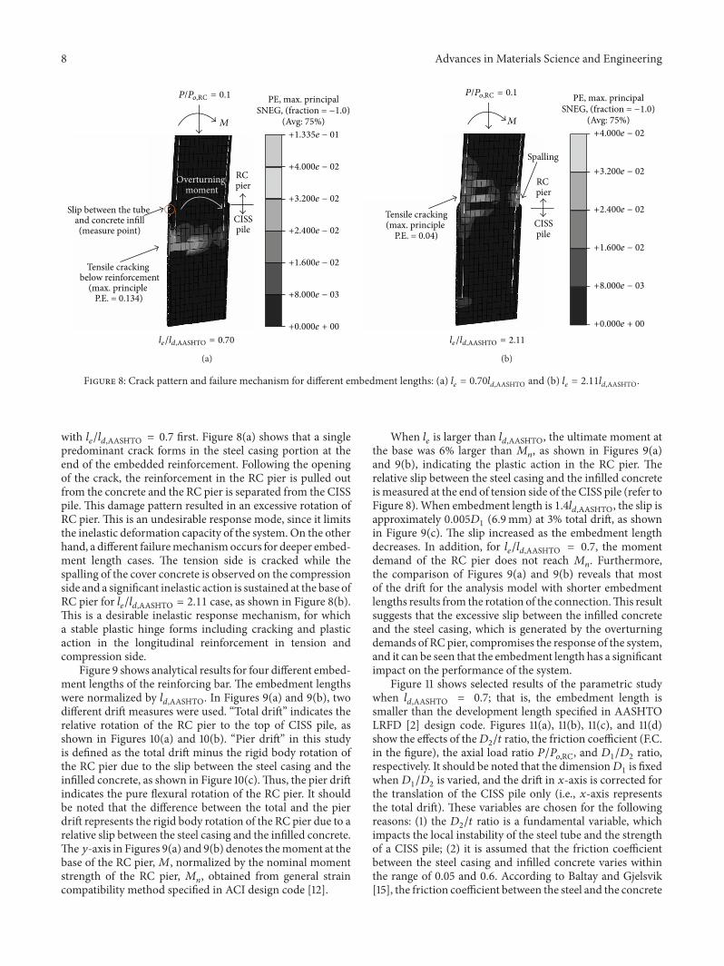
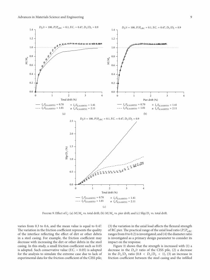
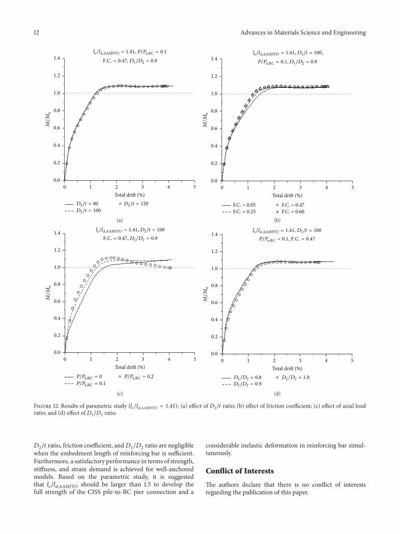