research article analysis of mimo diversity improvement
TRANSCRIPT
Research ArticleAnalysis of MIMO Diversity ImprovementUsing Circular Polarized Antenna
Jianquan Wang Zhaobiao Lv and Xinzhong Li
Network Technology Research Institute China United Network Communications Corporation Ltd Beijing 100048 China
Correspondence should be addressed to Xinzhong Li lixz139chinaunicomcn
Received 21 October 2013 Accepted 17 December 2013 Published 11 February 2014
Academic Editor Yue Gao
Copyright copy 2014 Jianquan Wang et alThis is an open access article distributed under the Creative Commons Attribution Licensewhich permits unrestricted use distribution and reproduction in any medium provided the original work is properly cited
MIMO (Multiple Input Multiple Output) technique is one of the important means to enhance the system capacity Diversity gaincould be acquired by using traditional plusmn45∘ dual-polarized antenna but in the scenario where multipath scattering is not strongpower-unbalance in two polarizations caused by polarizationmismatching between transmitting and receiving antennaswill reducediversity gain This problem can be effectively solved by using circular polarized antennas In this paper through theory analysisand test the improvement of MIMO diversity gain using circular polarization antenna is analyzed
1 Introduction
MIMO technique uses multitransmitting and multireceivingantennas to combat channel fading and increase capacity andspectrum efficiency MIMO system require low correlationbetween each pair of transmitting and receiving antennaelements in order to achieve a good independent channelfadingThere are two methods to dispose multi-antennaThefirst one is space isolation It is through the enough spacedistance to ensure non-correlation between each transmitreceive signals The other one is polarization isolation Itis through electromagnetic wave orthogonal polarization toensure non-correlation between each transmitreceive sig-nals Because the distance requirement is high for spaceisolation commonly more than 10 wavelengths the cost anddifficulty of space isolation antenna deployment is higher Sopolarization isolation proves to be an effective and economi-cal method to deploy multiantennas
For polarization isolation signals go through indepen-dent fading in orthogonal polarization direction and henceensure noncorrelation of two signals In traditional 2 times 2MIMO system two signals are transmitted by dual-polarizedbase station antenna in plusmn45∘ polarization direction andreceived by terminal in vertical and horizontal polarizationdirections During propagation polarization direction ofelectromagnetic wave deflects because of reflection refrac-tion and scattering When signals arrive to the receiver part
of signals in plusmn45∘ polarization direction could be coupledto vertical direction and the other part could be coupled tohorizontal direction Because of independent fading in ver-tical and horizontal direction polarization diversity gain canbe gained When the power of the signal in vertical directionis equal to that in horizontal direction maximum diversitygain can be gained [1 2]
In some typical scenes such as spacious indoor large pub-lic square and urban city area electromagnetic wave polar-ization deflection is not obvious because of less obstaclesWhen signals arrive to the receiver power of signals in plusmn45∘polarization direction coupled to vertical and horizontaldirection is not equal because electromagnetic wave polar-ization still keeps intrinsic polarization status in large partSystem diversity gain is limited because of influence of minorsignal There is even no diversity gain if two received signalspower has great difference [3]
Using circular polarized antenna in transmitter can solvethis problem effectively Two signals are transmitted throughleft-hand circular polarization and right-hand circular polar-ization wave (as shown in Figure 1) The noncorrelationbetween two signals is ensured by isolation of two circum-gyrate directions
The rest of this paper is organized as follows MIMOsystem principle and channel capacity are introduced inSection 2 Section 3 gives the principle analysis of MIMOdiversity improvement using circular polarized antenna
Hindawi Publishing CorporationInternational Journal of Antennas and PropagationVolume 2014 Article ID 570923 9 pageshttpdxdoiorg1011552014570923
2 International Journal of Antennas and Propagation
(Figure 9) The result of MIMO channel capacity improve-ment is given in Section 5 and conclusions are given inSection 6
2 MIMO System and Channel Capacity
21 MIMO System Each channel between a pair of trans-mitting and receiving antennas is considered to be a MIMOsubchannel Assume that there are 119899
119877transmitting antennas
and 119899119879receiving antennas Hence there are 119899
119877times 119899119879channel
matrix which we name as channel matrix119867
119867 =
100381610038161003816100381610038161003816100381610038161003816100381610038161003816100381610038161003816100381610038161003816
ℎ11
ℎ12
sdot sdot sdot ℎ1119899119879
ℎ21
ℎ22
sdot sdot sdot ℎ2119899119879
d
ℎ1198991198771
ℎ1198991198772
sdot sdot sdot ℎ119899119877119899119879
100381610038161003816100381610038161003816100381610038161003816100381610038161003816100381610038161003816100381610038161003816
(1)
The element of 119867 is a subchannel between one pair oftransmitting and receiving antennas When the distance ofeach pair is large enough every signal between transmittingand receiving antennas is independent Then the rank ofthe matrix 119867 will be large even full when under idealcircumstances Vice versa when near the rank will be smallbecause the signals are correlated to each other From theabove we can conclude that the channel capacity of MIMO ishighly related with the matrix119867 If the channel condition ofthe transmitting point is unknown but the index of thematrix and the overall transmission power 119875 are fixedthe overall power can be designated to every transmissionantenna averagely Then the capacity can be calculated as
119862 = log2
det(119868119899119877+
119875
119899119879sdot 1198730
119867119867119867
) (2)
22 MIMO Channel Capacity The model of the channelcapacity can be considered as a complex baseband linearsystem It has been assumed that there are 119899
119879transmission
antennas 119899119877receiving antennas and the overall transmission
power 119875 Then the power of each antenna will be 119875119899119879and
the receiving power of receiving antenna will be equal to theoverall transmission power If the channel is interfered byAWGN and the noise power of each antenna is119873
0 then SNR
of every receiving antenna will be
120589 =119875
119899119879sdot 1198730
(3)
When the bandwidth of transmitting signal is narrowenough the frequency response of the channel is flat and thechannel matrix is considered to be matrix119867 whose elementℎ119895119894shows the channel fading index between transmission
antenna 119894 and receiving antenna 119895 the capacity can be shownas
119862 = log2
[det(119868min +120589
119899119879
119876)] (4)
where ldquominrdquo is the smaller of 119899119879and 119899119877andmatrix119876 is shown
as
119876 = 119867119867
119867 119899119877gt 119899119879
119867119867119867
119899119877lt 119899119879
(5)
221 The MIMO System of ldquoall 1rdquo Channel Matrix [2] If thecorrelation detection technology is used at receiving pointand then all the signals of each antenna will have the samefrequency and phase As a result all signals which come from119899119879transmitting antennas can be considered the sameConsidering 119904
119894= 119904 and 119894 = 1 2 119899
119879 the signal coming
from antenna 119895 can be shown as 119903119895= 119899119879119904119894= 119899119879119904 119895 =
1 2 119899119877 the power of the dedicated antenna is shown as
119899119879
2
(119875119899119879) = 119899119879119875 and SNR of each receiving antenna is 119899
119879120589
the overall SNR of receiving point is shown as 119899119879119899119877120589
This multiantenna system can be seen as a sole-antennasystemwhich has 119899
119879119899119877diversity gainsThe capacity is shown
as
119862 = log2
(1 + 119899119879119899119877120589) (6)
If the receiving point adopts noncoherent detectiontechnology the SNR of each receiving antenna will still be 120589and the overall SNRwill be 119899
119877120589This sole-antenna system has
an 119899119877gain compared to the typical sole-antenna system The
capacity is shown as
119862 = log2
(1 + 119899119877120589) (7)
222 The MIMO System of Orthogonal Transmitting Channel[2] TheMIMO system of orthogonal transmitting channel isa subsystem whose subchannel is orthogonal Assuming theamount of antennas of transmitting and receiving point is thesame (119899
119879= 119899119877= 119871) the matrix can be shown as 119867 = radic119871119868
119871
(119868119871is the unit matrix of 119871 times 119871) From (2) we can get the
capacity as
119862 = log2
[det(119868119871+120589
119871
119867119867119867
)] = log2
[det(119868119871+120589
119871
119871119868119871)]
= log2
[det (1 + 120589)] = log2
(1 + 120589)119871
= 119871log2
(1 + 120589)
(8)
The channel capacity gets a gain of 119871 compared to the oldsystem due to the coupling of subchannels of each antenna
If the channel index is changed randomly the capacityof MIMO channel will be a random variable The averagecapacity is
119862 = 119864log2
[det(119868119903+
120589
119899119879
119876)] (9)
where 119903 is the rank of matrix119867 119903 = min(119899119879 119899119877)
3 Analysis of MIMO Diversity ImprovementUsing Circular Polarized Antenna
31 PolarizationMatching Polarization is an important char-acter of antennas It gives the changing orbit of electric vectorand time in certain conditions Normally the wave along +119911can be shown in 119909-axis and 119910-axis as
119864119909= 119864119909119898
cos (120596119905 minus 119896119911 + 120593119909)
119864119910= 119864119910119898
cos (120596119905 minus 119896119911 + 120593119910)
(10)
International Journal of Antennas and Propagation 3
From the relationship of 119864119909rsquos and 119864
119910rsquos amplitude and
phase we can conclude that the electromagnetic wave hasthree polarizations linear polarization circular polarizationand elliptical polarization If 119911 = 0
119864119909= 119864119909119898
cos (120596119905 minus 120593119909)
119864119910= 119864119910119898
cos (120596119905 minus 120593119910)
(11)
When 120593119910minus 120593119909= 0 or 120593
119910minus 120593119909= plusmn120587
119864119909= 119864119909119898
cos120596119905
119864119910= 119864119910119898
cos120596119905(12)
Electromagnetic amplitude 119864 = radic1198642
119909
+ 1198642
119910
=
radic1198642
119909119898
+ 1198642
119910119898
cos120596119905 and phase
120572 = arctg(119864119910
119864119909
) =
arctg(119864119910119898
119864119909119898
) (120601119909minus 120601119910= 0)
minusarctg(119864119910119898
119864119909119898
) (120601119909minus 120601119910= plusmn120587)
(13)
As shown above the resultant wave changes along with timebut the orbit is in the line which has a degree 120572 over 119909-axisIt is linear polarization wave
When 120593119910minus 120593119909= ∓(1205872) 119864
119909119898= 119864119910119898
= 119864119898
119864119910= 119864119898cos(120596119905 ∓ 120587
2
) = plusmn119864119898sin (120596119905) (14)
Electromagnetic amplitude 119864 = radic1198642
119909
+ 1198642
119910
= 119864119898 The resul-
tant wave is not changed with time but direction changedwith time The vector of electronic field is rotating withangular velocity 120596 It is circular polarization wave
When 120593119910minus 120593119909= 120579 119864
119909119898= 119864119910119898
119864119909= 119864119909119898
cos120596119905
119864119910= 119864119910119898(cos120596119905 + 120579)
(15)
When 119905 is subtracted
1198642
119909
1198642
119909119898
+
1198642
119910
1198642
119910119898
minus
2119864119909119864119910
119864119909119898119864119910119898
cos 120579 = sin2120579 (16)
The degree of the ovalrsquos axis over 119909-axis is
tan 2120579 =2119864119909119898119864119910119898
cos1205931198642
119909119898
minus 1198642
119910119898
(17)
All the vectors are rotating with an oval shape As a resultthis polarization wave is named as elliptical polarizationwave
Only when the transmitting and receiving antennamatchcorrectly can the antenna achieve the best receiving effect
When vertical polarized antenna is receiving verticalpolarized wave the transmitting wave will be shown as
= 1198861199101198640cos (119908119905 minus 120573119911)
119890119908= 119886119910
(18)
The receiving antenna is shown as
= 1198861199101198640cos (119908119905 minus 120573119911)
119890119886= 119886119910
(19)
Polarization matching index is
PLF = 1003816100381610038161003816 119890119908 sdot 119890lowast
119886
1003816100381610038161003816
2
=10038161003816100381610038161003816119886119910sdot ( 119886119910)10038161003816100381610038161003816
2
= 1 (20)
The receiving antenna will get the maximum power fromthe wave and now the transmitting and receiving antennamatch perfectly
When circular polarized antenna is receiving linear polar-ized wave the transmitting wave is shown as
= 1198861199101198640cos (119908119905 minus 120573119911)
119890119908= 119886119910
(21)
For the receiving antenna
= 119886119909119864119898cos (120596119905 minus 120573119911) + 119886
119910119864119898cos(120596119905 minus 120573119911 + 120587
2
)
119890119886=
1
radic2
( 119886119909+ 119886119910)
(22)
Polarization matching index is
PLF = 1003816100381610038161003816 119890119908 sdot 119890lowast
119886
1003816100381610038161003816
2
=
10038161003816100381610038161003816100381610038161003816
119886119909sdot1
radic2
( 119886119909+ 119886119910)
10038161003816100381610038161003816100381610038161003816
2
=1
2
(23)
The antenna will get half the power which means a 3 dBloss The same result comes with linear polarized antennareceiving circular polarized wave
When left-hand circular polarized antenna is receivingleft-hand circular polarized wave the wave is shown as
= minus 1198861199091198641198981
sin (120596119905 minus 119896119911) + 1198861199101198641198981
cos (120596119905 minus 119896119911)
119890119908=
1
radic2
(minus 119886119909+ 119886119910)
(24)
For the receiving antenna
= 1198861199091198641198982
cos (120596119905 minus 119896119911) + 1198861199101198641198982
sin (120596119905 minus 119896119911)
119890119886=
1
radic2
( 119886119909+ 119886119910)
(25)
Polarization matching index is
PLF = 1003816100381610038161003816119890119908sdot 119890lowast
119886
1003816100381610038161003816
2
=
10038161003816100381610038161003816100381610038161003816
1
radic2
(minus 119886119909+ 119886119910) sdot
1
radic2
( 119886119909+ 119886119910)
10038161003816100381610038161003816100381610038161003816
2
= 0
(26)
4 International Journal of Antennas and Propagation
x
y
0
EEy
Ex
(a)
x
y
0
EEy
Ex
(b)
Figure 1 Left-hand circular polarization (LHCP) wave and right-hand circularly polarized (RHCP) wave
The receiving antenna cannot get power because theydid not match in rotation direction The same result comeswith horizontalvertical polarized antenna receiving verticalhorizontal polarized wave
When two linear polarized antennas which are in verticaland horizontal direction are receiving circular polarizedwave the wave is shown as
= 119886119909119864119898cos (120596119905 minus 120573119911) + 119886
119910119864119898cos(120596119905 minus 120573119911 + 120587
2
)
119890119908=
1
radic2
( 119886119909+ 119886119910)
(27)
For the receiving antenna
119909= 119886119909119864119898cos (120596119905 minus 120573119911)
119910= 119886119910119864119898cos(120596119905 minus 120573119911 + 120587
2
)
119890119886=
1
radic2
( 119886119909+ 119886119910)
(28)
Polarization matching index is
PLF = 1003816100381610038161003816119890119908sdot 119890lowast
119886
1003816100381610038161003816
2
=
10038161003816100381610038161003816100381610038161003816
1
radic2
( 119886119909+ 119886119910) sdot
1
radic2
( 119886119909+ 119886119910)
10038161003816100381610038161003816100381610038161003816
2
= 1
(29)
The receiving antennasmatch transmittingwave in polar-ization direction perfectly
32 Cross Polarization Ratio and Polarization Leakage RatioCross polarization ratio (Figure 2) which means the ratioof main polarization electromagnetic wave and orthogonalpolarization electromagnetic wave is the index which shows
Relat
ive g
ain
(dB)
CPR
120∘ sector
CopolarizationCross polpolarization
0
minus5
minus10
minus15
minus20
minus25
minus30
minus35
minus40180120600minus60minus120minus180
Azimuth (deg)
Figure 2 Cross-polarization ratio
the dual-polarization antennarsquos polarization features Thehigher the CRP is the better performance dual-polarizationantenna can achieve and hence the higher diversity gain
Due to the multipath effect of reflection and refractionthe electromagnetic wave will deflect to cross polarizationfrom main polarization If so the receiving power willnot be determined by CPR That means the CPR of dual-polarization antenna will be 0 dBThat will alsomaximize thediversity gain
However in some typical scenario which has less reflec-tion refraction and scattering the electromagnetic wave inUE side will keep the original polarization direction Themultipath effect cannot put half power of linear polarizationwave to the orthogonal polarization direction that is CPRdoes not come to ideal condition 0 dB
International Journal of Antennas and Propagation 5
120579
Ant1Ant2
Ant3
Ant4
Figure 3 Transmitting antenna and receiving antenna configura-tion
We define an index 120594 as polarization leakage ratio Itindicates the ratio of power received by UE antennas invertical polarization and horizontal polarization
120594 =119864119881
119864119877
(30)
120594 will be determined by CPR transmitting channeland receiving antenna When transmitting and receivingantennarsquos polarizationmatch perfectly andwe donot considerthe interference of transmitting channel the relationshipbetween 120594 and CPR will be
120594 =1
CPR (31)
33 Antenna Configuration and Transmitting ChannelAssume two transmitting antennas are Ant
1and Ant
2 They
keep vertical to each other and have 45∘ included angle withvertical direction (dual-polarization antenna configuration)as we can get fromFigure 3The samewith receiving antennasnamed Ant
3and Ant
4which have a degree 120579 120579 is determined
by the direction of equipmentAssume Ant
1rsquos and Ant
2rsquos linear polarization component
are 1198791199011
and 1198791199012 They have the same amplitude and a
90∘ phase difference That means circular polarized wave istransmitted
1198791199011= 119864119898cos (120596119905 minus 120573119911)
1198791199012= 119864119898cos(120596119905 minus 120573119911 minus 120587
2
)
(32)
This is a left-hand circular polarized wave When 1198791199012
=
119864119898cos(120596119905 minus 120573119911 + (1205872)) it will be changed to a right-hand
circular polarized waveThe channelmodel (Figure 4) is based on references [1 3ndash
5] Matrix119867 shows each channel function relationship
119867 = [Γ1111989011989512060111
Γ1211989011989512060112
Γ2111989011989512060121
Γ2211989011989512060122
] (33)
Γ1111989011989512060111 and Γ
2211989011989512060122 show the cross-coupling relationship of
1198791199011
to 1198771199011
and 1198791199012
to 1198771199012
independently Γ is a random
Transmitter Receiver
Tp1
Tp2
Γ11ej12060111
Γ22ej12060122
Γ12ej12060112
Γ21ej12060121
Rp1
Rp2
Figure 4 Transmission channel model
variable that shows the multipath fading degree References[2 6 7] give the relevant testing result 120601 is the signal randomphase which is in [0 2120587)
34 Received Signal Power Ratio Based upon antenna config-uration and channel model two received signals 119877
1199011and 119877
1199012
are shown below
[1198771199011
1198771199012
] = [Γ1111989011989512060111
Γ1211989011989512060112
Γ2111989011989512060121
Γ2211989011989512060122
] [sin 120579 minus cos 120579cos 120579 sin 120579 ] [
1198791199011
1198791199012
] (34)
1198771199011
and 1198771199012
signal strength is expressed as
119864 [1198772
1199011
] = 1198642
119898
sdot 119864 [Γ2
11
] + 119864 [Γ2
12
]
119864 [1198772
1199012
] = 1198642
119898
sdot 119864 [Γ2
21
] + 119864 [Γ2
22
]
(35)
From 1198771199011
and 1198771199012 we can get the received LHCP wave
power ratio in Ant3and Ant
4
120594LHCP =119864 [1198772
1199012
]
119864 [1198772
1199011
]
=
119864 [Γ2
21
] + 119864 [Γ2
22
]
119864 [Γ2
11
] + 119864 [Γ2
12
]
(36)
From the above we can conclude that polarization leak-age ratio is not decided by the direction relationship 120579 butcompletely by channel condition
If linear polarized antenna is adopted in transmittingpoint 119879
1199011= 119864119898cos(120596119905 minus 120573119911) and 119879
1199012= 0 we can get
119864 [1198772
1199011
] = 1198642
119898
sdot 119864 [Γ2
11
] sdot sin2120579 + 119864 [Γ212
] sdot cos2120579
119864 [1198772
1199012
] = 1198642
119898
sdot 119864 [Γ2
21
] sdot sin2120579 + 119864 [Γ222
] sdot cos2120579 (37)
The received signal strength ratio in Ant3and Ant
4is
1205941198791199011
=
119864 [Γ2
11
] sdot sin2120579 + 119864 [Γ212
] sdot cos2120579119864 [Γ2
21
] sdot sin2120579 + 119864 [Γ222
] sdot cos2120579
=
119864 [Γ2
11
] sdot tan2120579 + 119864 [Γ212
]
119864 [Γ2
21
] sdot tan2120579 + 119864 [Γ222
]
(38)
6 International Journal of Antennas and Propagation
0 45 90 135 180 225 270 315 360minus30
minus25
minus20
minus15
minus10
minus5
0
5
10
15
20
25
30
120579 (∘)
120594(d
B)
120594T1199011120594T1199012120594RHCP = 120594LHCP
Figure 5 Comparison of signal power balance between linearpolarized antenna and circular polarized antenna
When 1198791199011= 0 and 119879
1199012= 119864119898cos(120596119905 minus 120573119911)
1205941198791199012
=
119864 [Γ2
11
] sdot cos2120579 + 119864 [Γ212
] sdot sin2120579119864 [Γ2
21
] sdot cos2120579 + 119864 [Γ222
] sdot sin2120579
=
119864 [Γ2
11
] + 119864 [Γ2
12
] sdot tan2120579119864 [Γ2
21
] + 119864 [Γ2
22
] sdot tan2120579
(39)
When linear polarization antenna is adopted in trans-mitting point polarization leakage ratio is determined bychannel condition and direction relationship 120579
In the scenarios which have less multipath effect 119864[Γ221
]
and 119864[Γ212
] are small The power coupling of different polar-ization channel is determined by CPR of dual-polarizationantenna
For circular polarized antenna
120594LHCP = 120594RHCP =119864 [Γ2
21
] + 119864 [Γ2
22
]
119864 [Γ2
11
] + 119864 [Γ2
12
]
=
119864 [Γ2
21
] 119864 [Γ2
11
] + 119864 [Γ2
22
] 119864 [Γ2
11
]
1 + 119864 [Γ2
12
] 119864 [Γ2
11
]
asympCPRminus1 + 11 + CPRminus1
= 1
(40)
Dual-polarization
radiator
LHCP RHCP
Hybrid combiner
Feed
ing
netw
ork
for +
45po
lariz
atio
n
Feed
ing
netw
ork
forminus
45po
lariz
atio
n
+45∘ port minus45∘ port
Figure 6 The realization of CPA by plusmn45∘ dual-polarized antenna
For linear polarized antenna
1205941198791199011
=
119864 [Γ2
11
] sdot tan2120579 + 119864 [Γ212
]
119864 [Γ2
21
] sdot tan2120579 + 119864 [Γ222
]
=
tan2120579 + 119864 [Γ212
] 119864 [Γ2
11
]
(119864 [Γ2
21
] 119864 [Γ2
11
]) sdot tan2120579 + 119864 [Γ222
] 119864 [Γ2
11
]
asymptan2120579 + CPRminus1
CPRminus1 sdot tan2120579 + 1
1205941198791199012
=
119864 [Γ2
11
] + 119864 [Γ2
12
] sdot tan2120579119864 [Γ2
21
] + 119864 [Γ2
22
] sdot tan2120579
=
1 + (119864 [Γ2
12
] 119864 [Γ2
11
]) sdot tan2120579119864 [Γ2
21
] 119864 [Γ2
11
] + (119864 [Γ2
22
] 119864 [Γ2
11
]) sdot tan2120579
asymp1 + CPRminus1 sdot tan2120579CPRminus1 + tan2120579
(41)
International Journal of Antennas and Propagation 7
0 40 80 120 160 200 240 280 320 360
minus50
minus40
minus30
minus20
minus10
0
10
Angle (∘)
Gai
n (d
B i)
(a) +45∘ polarized antenna pattern
0 40 80 120 160 200 240 280 320 360
minus50
minus40
minus30
minus20
minus10
0
10
Angle (∘)
Gai
n (d
B i)
(b) minus45∘ polarized antenna pattern
0 40 80 120 160 200 240 280 320 360
minus50
minus40
minus30
minus20
minus10
0
10
Angle (∘)
1710MHz1750MHz1795MHz
1850MHz1880MHz
Gai
n (d
B i)
(c) Left-hand polarized antenna pattern
0 40 80 120 160 200 240 280 320 360
minus50
minus40
minus30
minus20
minus10
0
10
Angle (∘)
1710MHz1750MHz1795MHz
1850MHz1880MHz
Gai
n (d
B i)
(d) Right-hand polarized antenna pattern
Figure 7 Comparison of pattern between linear polarized antenna and circular polarized antenna
We can conclude that for circular polarized antenna thepower of circular polarization wave received by two receivingantennas is equal for linear polarized antenna the powerreceived by two receiving antennas is decided by CPR and 120579
The received signal power balance of circular polarizedantenna and linear polarized antenna can be compared (seeTable 1 and Figure 7) The multipath fading vector Γ obeysRayleigh distribution Considering the condition of dual-polarization antenna CPR is almost 30 dB To better show thereceived signal power balance of circular polarized antennaand linear polarized antenna the simulation is shown inFigure 5
Aswe can see in the same channel condition the receivedsignal power balance of linear polarized antenna power isdecided by antenna polarization isolation When 120579 = 1205874
or 31205874 the received signal power ratio is equal to circularpolarization antenna It is not realistic to keep the anglebetween transmitting and receiving antennas still along the
whole communication processThatmeans the signal balancecan be harmed by the slight change of antenna angle Thatmeans the signal balance can be harmed by the slight changeof antenna angle that is reduce the polarization diversitygain
4 Design of Circular Polarization Antenna
Assume antenna lies along 119911-axis and at the plane of yoz forplusmn45∘ dual-polarization antenna the Tx (or Rx) signal can bedecomposed as
119864minus45
= 119864120579minus 119864120593 (42a)
119864+45
= 119864120579+ 119864120593 (42b)
where 119864120579and 119864
120593are the complex signals in theta and phi
polarization respectively
8 International Journal of Antennas and Propagation
Table 1 Comparison of pattern performance between linear polar-ized antenna and circular polarized antenna
LHCP RHCP +45 minus45Gain 17817 17191 17784 17863HPBW 66525 6778 67032 66784Front-to-back ratio 31773 27836 29258 29804Azimuth beam squint minus051985 051779 minus0018224 03826Cross polar ratio-0 28684 40389 30067 35675Cross polar ratio-60 14077 11241 10484 12035
For LHRH dual circular polarization antenna the Tx (orRx) signal can be decomposed as
119864LH = 119864120579minus 119895119864120593 (43a)
119864RH = 119864120579+ 119895119864120593 (43b)
where 119895 = radicminus1The most intuitive method is to combine the plusmn45∘ ports
of the dual-polar antenna by 90∘ hybrid with a 90∘ phasedifference The schematic diagram is illustrated in Figure 6
Contrast can be seen from the test results circular polar-ized antenna performance is consistent with linearly polar-ized antenna Circular polarized antenna axis radio value issmall enough electromagnetic wave can maintain a goodcircular polarization characteristic That is the performanceof the existing network will not be impacted using circularpolarized antenna
5 The Enhancement of MIMO Diversity UsingCircular Polarized Antenna
At line-of-sight environment the power received fromantenna can be small and the diversity gain is limited Thepower of two received antennas is balanced when circularpolarization antenna is adopted However the power of tworeceived antennas is decided by antenna angle when linearpolarization antenna is adopted We give a better explanationof the relationship between received power balance andMIMO diversity gain loss by the calculation of computer
The power of two received antennas is not even whenlinear polarization antenna is adopted The diversity gain islimited by the signal that has the smaller power That meansthe SNR of receiving antenna is lowered According to (9) wecan get the curve of channel capacity as in Figure 8
By using circular polarization in the actual wireless envi-ronment in the realization of MIMO through the cell 1 andcell 2 test results can be seen that the average systemthroughput has relative 11ndash18 ascension and has 25 ofthe highest lifting capacity
6 Conclusions
MIMO diversity improvement using circular polarizedantenna is given by principle analysis and test System gaindrops because of power imbalance in two receiving antennasin the sceneswhich donot have enoughmultipath effectwhen
0 45 90 135 180 225 270 315 3602
3
4
5
6
7
8
9
10
11
Chan
nel c
apic
ity (b
its
Hz)
Linear polarizationCircular polarization
120579 (∘) SNR = 16dB
Figure 8 Comparison of MIMO channel capacity between linearpolarized antenna and circular polarized antenna
0
200
400
600
800
1000
1200
1400
1600
1800
Cell 1 Cell 2
1427 14671582
1725
Throughput (kbps)
Linear polCircular pol
Figure 9 Test result ofMIMOdiversity improvement using circularpolarized antenna
using traditional plusmn45∘ dual-polarization antenna Whenusing circular polarized antenna in transmitting point thisproblem can be solved effectively Two signals are transmittedthrough left-hand polarized and right-hand polarized elec-tromagnetic waves The noncorrelation between two signalsis ensured by isolation of two circum-gyrate directions
Conflict of Interests
The authors declare that there is no conflict of interestsregarding the publication of this paper
International Journal of Antennas and Propagation 9
References
[1] 3GPP TS 25 211 V8 0 0 Physical channels and mapping oftransport channels onto physical channels (FDD)
[2] 3GPP TR 25 876 V7 0 0 (2007-03) Multiple Input MultipleOutput in UTRA
[3] Y C Huang and B Senadji ldquoOrientation analysis for antennadiversity using circular polarizationrdquo in Proceedings of the 2ndInternational Conference on Signal Processing and Communica-tion Systems (ICSPCS rsquo08) Gold Coast Australia December2008
[4] R G Vaughan ldquoPolarization diversity in mobile communica-tionsrdquo IEEE Transactions on Vehicular Technology vol 39 no 3pp 177ndash186 1990
[5] W C Y Lee and Y S Yeh ldquoPolarization diversity system formobile radiordquo IEEE Transactions on Communications vol 20no 5 pp 912ndash923 1972
[6] J D Kraus and R J Marhefka Antennas for all ApplicationsMcGraw-Hill New York NY USA 3rd edition 2002
[7] A Kajiwara ldquoCircular polarization diversity with passive reflec-tors in indoor radio channelsrdquo IEEE Transactions on VehicularTechnology vol 49 no 3 pp 778ndash782 2000
International Journal of
AerospaceEngineeringHindawi Publishing Corporationhttpwwwhindawicom Volume 2014
RoboticsJournal of
Hindawi Publishing Corporationhttpwwwhindawicom Volume 2014
Hindawi Publishing Corporationhttpwwwhindawicom Volume 2014
Active and Passive Electronic Components
Control Scienceand Engineering
Journal of
Hindawi Publishing Corporationhttpwwwhindawicom Volume 2014
International Journal of
RotatingMachinery
Hindawi Publishing Corporationhttpwwwhindawicom Volume 2014
Hindawi Publishing Corporation httpwwwhindawicom
Journal ofEngineeringVolume 2014
Submit your manuscripts athttpwwwhindawicom
VLSI Design
Hindawi Publishing Corporationhttpwwwhindawicom Volume 2014
Hindawi Publishing Corporationhttpwwwhindawicom Volume 2014
Shock and Vibration
Hindawi Publishing Corporationhttpwwwhindawicom Volume 2014
Civil EngineeringAdvances in
Acoustics and VibrationAdvances in
Hindawi Publishing Corporationhttpwwwhindawicom Volume 2014
Hindawi Publishing Corporationhttpwwwhindawicom Volume 2014
Electrical and Computer Engineering
Journal of
Advances inOptoElectronics
Hindawi Publishing Corporation httpwwwhindawicom
Volume 2014
The Scientific World JournalHindawi Publishing Corporation httpwwwhindawicom Volume 2014
SensorsJournal of
Hindawi Publishing Corporationhttpwwwhindawicom Volume 2014
Modelling amp Simulation in EngineeringHindawi Publishing Corporation httpwwwhindawicom Volume 2014
Hindawi Publishing Corporationhttpwwwhindawicom Volume 2014
Chemical EngineeringInternational Journal of Antennas and
Propagation
International Journal of
Hindawi Publishing Corporationhttpwwwhindawicom Volume 2014
Hindawi Publishing Corporationhttpwwwhindawicom Volume 2014
Navigation and Observation
International Journal of
Hindawi Publishing Corporationhttpwwwhindawicom Volume 2014
DistributedSensor Networks
International Journal of
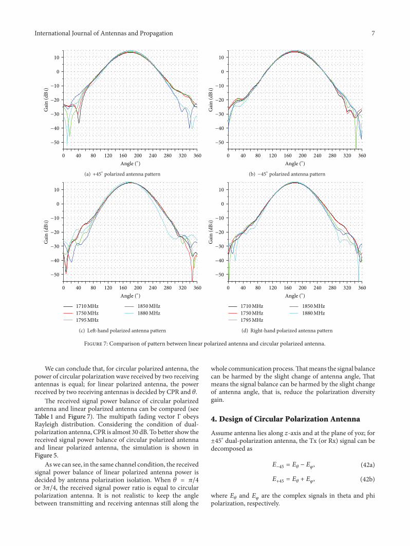

International Journal of
AerospaceEngineeringHindawi Publishing Corporationhttpwwwhindawicom Volume 2014
RoboticsJournal of
Hindawi Publishing Corporationhttpwwwhindawicom Volume 2014
Hindawi Publishing Corporationhttpwwwhindawicom Volume 2014
Active and Passive Electronic Components
Control Scienceand Engineering
Journal of
Hindawi Publishing Corporationhttpwwwhindawicom Volume 2014
International Journal of
RotatingMachinery
Hindawi Publishing Corporationhttpwwwhindawicom Volume 2014
Hindawi Publishing Corporation httpwwwhindawicom
Journal ofEngineeringVolume 2014
Submit your manuscripts athttpwwwhindawicom
VLSI Design
Hindawi Publishing Corporationhttpwwwhindawicom Volume 2014
Hindawi Publishing Corporationhttpwwwhindawicom Volume 2014
Shock and Vibration
Hindawi Publishing Corporationhttpwwwhindawicom Volume 2014
Civil EngineeringAdvances in
Acoustics and VibrationAdvances in
Hindawi Publishing Corporationhttpwwwhindawicom Volume 2014
Hindawi Publishing Corporationhttpwwwhindawicom Volume 2014
Electrical and Computer Engineering
Journal of
Advances inOptoElectronics
Hindawi Publishing Corporation httpwwwhindawicom
Volume 2014
The Scientific World JournalHindawi Publishing Corporation httpwwwhindawicom Volume 2014
SensorsJournal of
Hindawi Publishing Corporationhttpwwwhindawicom Volume 2014
Modelling amp Simulation in EngineeringHindawi Publishing Corporation httpwwwhindawicom Volume 2014
Hindawi Publishing Corporationhttpwwwhindawicom Volume 2014
Chemical EngineeringInternational Journal of Antennas and
Propagation
International Journal of
Hindawi Publishing Corporationhttpwwwhindawicom Volume 2014
Hindawi Publishing Corporationhttpwwwhindawicom Volume 2014
Navigation and Observation
International Journal of
Hindawi Publishing Corporationhttpwwwhindawicom Volume 2014
DistributedSensor Networks
International Journal of