research activities @er2c
TRANSCRIPT

Research Activities @ER2C
Sritrusta Sukaridhoto, PhD
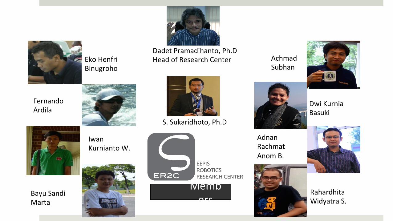
Members
Dadet Pramadihanto, Ph.D Head of Research Center
S. Sukaridhoto, Ph.D
Achmad Subhan
Dwi Kurnia Basuki
Adnan Rachmat Anom B.
Rahardhita Widyatra S.
Eko Henfri Binugroho
Fernando Ardila
Iwan Kurnianto W.
Bayu Sandi Marta

Research projects:
¤ Humanoid Robot ¤ Flow ROS (Robotic Operating Systems) ¤ Adult Humanoid Robot Framework
¤ Virtual Reality and Visualization ¤ VR Lab ¤ Smart Presentation System ¤ 3D Reconstruction
¤ Internet of Things ¤ Portable Vital Sign Kit ¤ Posyandu Smart Bracelet Reminder ¤ Mini Photo Bot ¤ ROV for Water Environment Monitoring and Data Aquisition

FLoW ROS Funding: Penelitian Unggulan Perguruan Tinggi – DIKTI (2013-2014) Team: Dadet Pramadihanto Ph.D, Sritrusta Sukaridhoto Ph.D, Achmad Subhan Khalillullah MT, Adhe W, Tito P

FLoW Robotic Operating System Microkernel Based Real Time Operating System
FLoW Robotics Operating System Architecture
Motivation • Advance Robotics
Use of Mult itasking in Complex Robotics Environment.
• Advance Controller
The growth of mini PC and SoC (System on Chip).
• Robotics for Education and Competition
Provide robustness and easy of use.
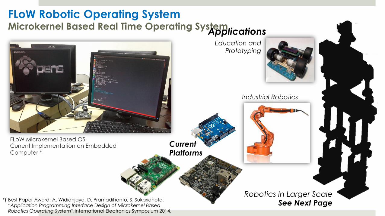
FLoW Robotic Operating System Microkernel Based Real Time Operating System
Current Platforms
Applications Education and
Prototyping
Industrial Robotics
Robotics In Larger Scale See Next Page *) Best Paper Award: A. Widianjaya, D. Pramadihanto, S. Sukaridhoto.
“Application Programming Interface Design of Microkernel Based Robotics Operating System”.International Electronics Symposium 2014.
FLoW Microkernel Based OS Current Implementation on Embedded Computer *

Distributed Control System Independent and Synchronized Controller
FLoW Humanoid Robot By ER2C PENS
Main Computer Placed inside the body
Head Control
Arms Movement
Legs Movement
Body and Balancing
Networks CAN, Ethernet

FLoW Humanoid Robot Funds: • Dikti PKM 2015 (3 tim) • Penelitian Unggulan Perguruan Tinggi – DIKTI (2013-2014) Team: Dadet. P, S. Sukaridhoto, A. Subhan, R. Sanggar, Anom Besari, Eko Henfri, Fernando A, Bayu Setiawan, M. Zulfi, Oxsy G, BA Putra, Robyarta H, Teguh Bintang

FLoW Humanoid Robots ¤ Specification
¤ Mechanical ¤ Complexities: 32 DoF mostly in Parallel Mechanism ¤ Height: 165 cm ¤ Tptal weight ~ 45 kg
¤ Electronics ¤ ARM based microcontroller ¤ Intel based PC as main computer
¤ Sensors ¤ IMU’s ¤ Camera’s
¤ Actuators ¤ Servo motors: Dynamixel ¤ Linear Motor
¤ Using FLoW microkernel OS

Robot Segment Degree of Freedom
Eye 2
Head 3
Neck 2
Right Hand 5
Left Hand 5
Body 3
Right Leg 6
Left Leg 6
Sum 32
FLoW Humanoid Robot Mechanical Design: Eye

FLoW Humanoid Robot Mechanical Design: Body
Robot Segment Degree of Freedom
Eye 2
Head 3
Neck 2
Right Hand 5
Left Hand 5
Body 3
Right Leg 6
Left Leg 6
Sum 32

FLoW Humanoid Robot Mechanical Design: Arms
Robot Segment Degree of Freedom
Eye 2
Head 3
Neck 2
Right Hand 5
Left Hand 5
Body 3
Right Leg 6
Left Leg 6
Sum 32

FLoW Humanoid Robot Mechanical Design: Legs with Parallel Link Mechanism
Robot Segment Degree of Freedom
Eye 2
Head 3
Neck 2
Right Hand 5
Left Hand 5
Body 3
Right Leg 6
Left Leg 6
Sum 32

FLoW Humanoid Robot Electronic Design and Distributed Control System
µC 1Servo
Linear Motor
IMU
x6
x2
x2
Head
µC 2 Linear Motor
IMU
x3
x2
Body
µC 4Servo
Linear Motor
IMU
FSR
x12
x2
x3
x4
Right Leg
µC 5Servo
Linear Motor
IMU
FSR
x12
x2
x3
x4
Left Leg
µC 3 Servo
IMU
x10
x2
Hand
Motion Control
PC 2
SWITCH
CCD Camera
Speaker
x2
x2
MIC
Usart
Pwm
Usart
Usart
Pwm
Usart
Usart
Usart
Pwm
Usart
Adc
Usart
PwmUsart
Adc
Ethernet
Ethernet
Ethernet
Ethernet
Ethernet
Ethernet
x2
Intelligent Control
PC 1Ethernet
Ø This robot using 2 PC as main controller (mini MAC) that procced motion and intelligent control.
Ø Using 5 uC (mikrokontroler) as secondary controller that procced all data sensors dan actuators.
Ø PC2 as intelligent control have function to procced data from stereo camera. and send it to PC1.
Ø PC1 need data from sensors that will be send from uC1 – uC5 to procced motion control.
Ø PC1 procced it to knowing posture robot for the next gait, until knowing all value of each joint robot.
Ø PC1 send data each joint value to uC1 – uC5. and to actuator.

Real Time Operating System Support for Distributed Controlled Humanoid Robot
ARM Platform With FLoW OS in Body
ARM Cortex M4 with Embedded FLoW OS in Head
Intel Embedded Computer with Embedded FLoW OS Main Computer Communication Bus
And Networks CAN, Ethernet, WiFi
Distributed Computing in Humanoid Robot Each devices in separate Humanoid parts implements FLoW Operating System, and performs effective communications and synchronization for sensing and actuators control.
ARM Cortex M4 with Embedded FLoW OS in Arms
ARM Cortex M4 with Embedded FLoW OS in Legs

Virtual Reality and Visualization: Smart Presentation Systems
Fund: Dikti – PKM 2015 Team: S Sukaridhoto Ph.D, Dadet P Ph.D, M Hendrik Kurniawan

SMART PRESENTATION
SYSTEMS
C o m m o n l y p e o p l e u s e d m o u s e , keyboard and LCD projector to do the presentation. In the future, everyone want to use smart presentation systems

Virtual Reality and Visualization: VR-Lab
Fund: Seamolec 2014 Team: S Sukaridhoto Ph.D, Juang M, Prasetio N

INTERACTIVE VR-LAB ¤ Limitation for apparatus,
devices, materials, and etc for education practice.
VR-‐Lab is an educaIon lab simulator based on virtual reality that used 3D VR headset and hand gesture sensor.
SOLUTION

3D virtual reality glasses à Oculus RiM Development Kit 2 (DK2).
OCULUS Hand gesture sensor.
LEAPMOTION
3D simulator applicaIon that built using Unity 3D. 3D SIMULATION
“A Design of 3D Virtual Reality Chemical Lab with Hand Gesture Interaction for Education”, S. Sukaridhoto, Juang Mahmud Hasbulloh, Prasetio Nugroho, Lukman Hakim; The 5th Annual Basic Science International Conference, Malang, Indonesia, Feb 2015.

Virtual Reality and Visualization: 3D Reconstruction
Fund: Dikti - PKM 2015 Team: S Sukaridhoto Ph.D, M Safrodin MT, Bayu Sandy MT, Ade Fivers, Rhafi A, Hilfi S

Object
Kinect
Structure IO
Room
3D Object & Room mapping
System Design
3D Printer Mini Object
Virtual Reality
Environment Mapping Robot
Scanning using
3D Depth Sensor
3D Reconstruction
It uses for environment mapping and virtual reality
assets
Printout by using 3D printer
Internet of Things: Portable Vital Sign Kit
Fund: Dikti – PKM 2015 Team: S Sukaridhoto Ph.D, M Udinharun Ph.D, dr Dicky, Ari W, Muhajirin

Health problems
Posyandu is public medical center in the neighbor. But in Indonesia there are many people that not aware for health problems. People still difficult to reach Posyandu, no integrated health data.
Portable Vital Sign Kit Solution

This device will be use in Posyandu to help medic to do examine the patient in outside medical center. This device equip with multi health sensor, compact and portable. Can be connected to Internet to exchange patient data.

Internet of Things: Posyandu Smart Bracelet Reminder
Fund: DIKTI – PKM 2015 Team: S Sukaridhoto, M Alimudin, Faishal A, Adelin D

GSM MODEM
Smart Bracelet
System Overview
The elder patient, when they had medicine after medical check sometime they forgot about the schedule to take medicine. By using Smart Bracelet Reminder we can help them to give notification to take medicine.

Internet of Things: Mini Photo Bot
Fund: DIKTI – PKM 2015 Team: S Sukaridhoto Ph.D, Widi S MT, Yahya S
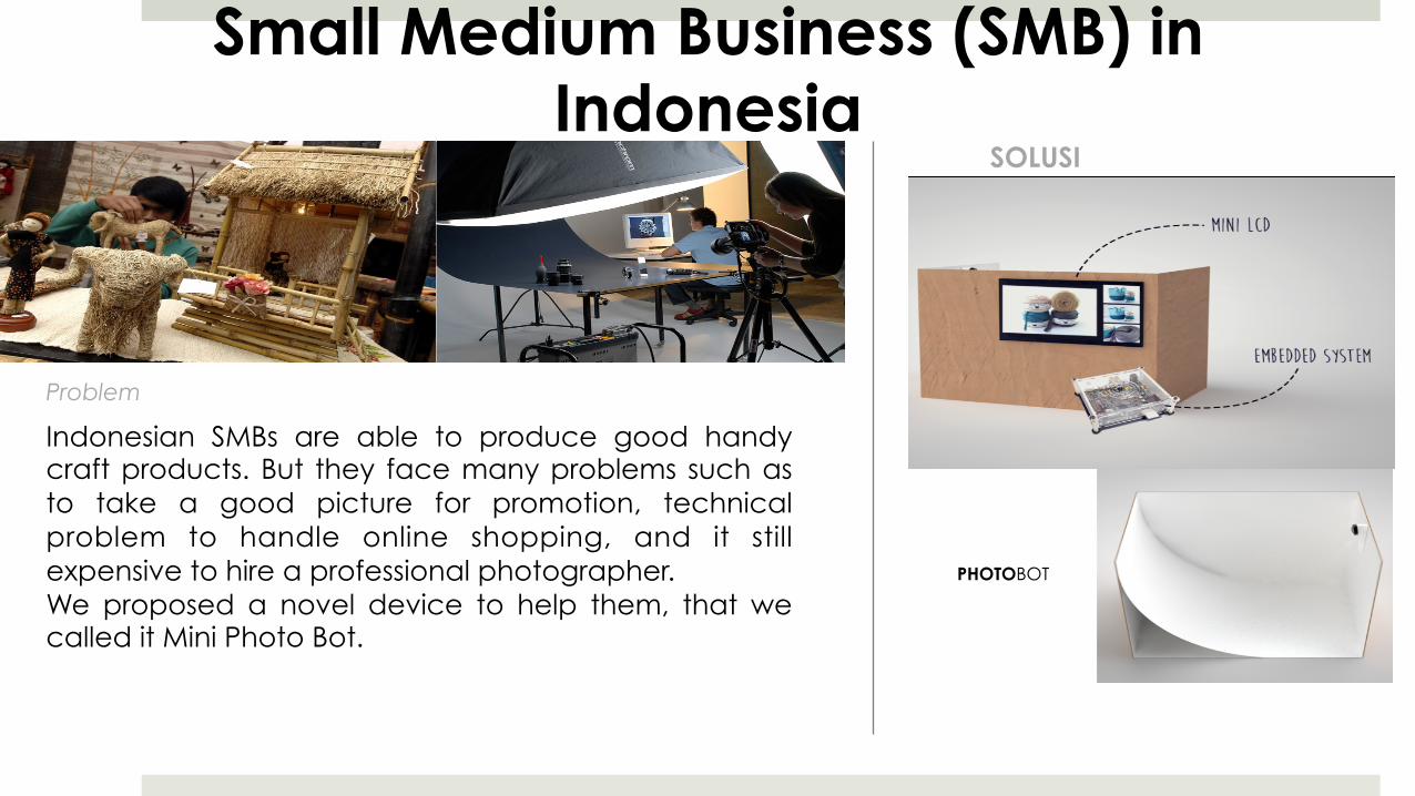
Small Medium Business (SMB) in Indonesia
Indonesian SMBs are able to produce good handy craft products. But they face many problems such as to take a good picture for promotion, technical problem to handle online shopping, and it still expensive to hire a professional photographer. We proposed a novel device to help them, that we called it Mini Photo Bot.
SOLUSI
PHOTOBOT
Problem

Mini Photo Bot
Mini Photo Bot is a small photo studio that equip with embedded system, LCD Touchscreen HD web camera, lighting and a software that can take a picture, modify and upload it to the specific online store.

MiniPhotoBot
When doing an experiments, the first step is to assemble the board to be the box and then assemble the others components like pandaboard, LCD Touchscreen, web camera, and lightling. The pandaboard has been overheat. It maybe because too many service running on the pandaboard.
Figure 16. Finishing miniphotobot
Figure 17. Miniphotobot
Figure 18. Picture result of miniphotobot
When using this miniphotobot, it takes about 23 seconds to do all the activity from taking picture, filtering, and then uploading to the destination server in the Internet. It is more faster than using a conventional photo studio.
Table 1. Time consumption
Phase Times Cosumption (s) Traditional Mini photo bot
Take Picture 3 3 Save Picture 5 - Access Filtering images Application
5 -
Images Filtering 150 10 Access Web 160 10 Upload Pictures 15 15 Total 338 38 4. Conclusion
Miniphotobot become important and useful for Small Medium Business(SMB) espsecially in sidoarjo who are not familiar with the technology. It help them to taking a picture, filtering, and uploading a picture of their product to the internet to sell their products in easy way. By using this mini photo bot, they can save a time much faster than using a traditional photo studio.
References [1] Dinas Koperasi dan UMKM Jawa Timur,
http://diskopumkm.jatimprov.go.id [2] Premiumclick, http://www.produkttest-coocoo.de/post/2012/08/06/Besser-Fotografieren-mit-dem-td-Mini-Fotostudio.aspx [3] Opvouwbare fotostudio, http://www.modelbrouwers.nl/phpBB3/viewtopic.php?t=19004. [4] Linkstar Photo Box, http://www.benel.eu/webshop/sale/linkstar-photo-box-flb-3236-2x18w-32x32-cm-foldable.html . [5] Home made photo box,
https://theartisticlife.wordpress.com/tag/homemade-photobox/ . [6] PandaBoard described,
http://en.wikipedia.org/wiki/PandaBoard . [7] Panda Board, http://pandaboard.org . [8] Online Store, http://bisnisukm.com [9] Microsoft Life cinema,
http://www.microsoft.com/hardware/en-us/p/lifecam-cinema [10] Odroid VU,
http://www.hardkernel.com/main/products/prdt_info.php?g_code=G140383714860

Internet of Underwater Things: ROV for Water Environment Monitoring and Data Acquisition
Fund: Penelitian Kerjasama Luar Negeri Dikti (2015 - …) Team: S Sukaridhoto Ph.D, Dadet P Ph.D, Taufiqurahman MT, Herman S, Andrie, M Alif Collaboration: Okayama Univ & Keio Univ - Jepang

The Internet of Underwater Things architecture
¤ The Internet of Underwater Things (IoUT) is a technological revolution of computing and communications.
¤ These devices sense, interpret and react to the environment due to the combination of the Internet, powerful tracking technologies and embedded sensors.
¤ The differences from ground-based IoT: ¤ Different communication technologies, ¤ Different tracking technologies, ¤ Difficulty of battery recharge, ¤ Different energy harvesting technologies, ¤ Different network density, and ¤ Different localization techniques
¤ Basic functionalities: ¤ Perception layer, ¤ Network layer and ¤ Network layer
affected by the Doppler shift. However, valuable insight has beengained into this area and several localization techniques specifi-cally designed for underwater wireless sensor networks that donot rely on time synchronization have been proposed (Chenget al., 2008, 2009; Liu et al., 2010; Luo et al., 2010).
The Localization with Directional Beacons (LDB) scheme (Luoet al., 2010) uses an AUV as a mobile beacon sender. The sensornodes can localize themselves silently by listening to two or morebeacons sent from the AUV. UPS (Cheng et al., 2008), a silentunderwater positioning scheme, relies on the time arrivals ofbeacon signals locally measured at a sensor to detect rangedifferences from the sensor to four anchor nodes. These measure-ments are averaged to estimate the 3-D sensor location throughtrilateration. In Cheng et al. (2009), a localization schemedesigned for large scale underwater wireless sensor networks isintroduced. Large-Scale Localization Scheme (LSLS) relies on TDoAmeasurements calculated locally at a sensor to measure the rangedifferences from the sensor to three anchors that can hear eachother. In Liu et al. (2010), the Asymmetrical Round Trip basedLocalization (ARTL) algorithm is proposed for localization inlarge-scale underwater wireless sensor networks. It uses ToAmeasurements to obtain the distance between ordinary nodesand beacon nodes (powerful nodes that can directly contact thesurface base station and are capable of self-localization).
3. IoUT architecture
The proposed IoUT architecture is shown in Fig. 1. It is dividedinto three layers, whose basic functionalities are summarized asfollows:
! Perception layer: It identifies objects and gathers information.It is formed mainly by underwater sensors, underwater vehi-cles, surface stations (sinks), monitoring stations (such astablet PC, smartphone, etc.), data storage tags, acoustic/radio/PIT tags and hydrophones/receivers/tag readers.! Network layer: It consists of a converged network made up of
wired/wireless privately owned networks, Internet, networkadministration systems, cloud computing platforms, etc. Itprocesses and transmits the information obtained from theperception layer.! Application layer: It is a set of intelligent solutions that apply
the IoUT technology to satisfy the needs of users.
Next, we describe in greater detail the components of each layer.
3.1. Perception layer
We distinguish between different components.
3.1.1. AUVs and underwater micro and nanosensorsAUVs are unmanned underwater vehicles, which operate inde-
pendently of direct human input. We can distinguish betweenautonomous vehicles able to operate (1) on the surface layer(Autonomous Surface Vehicles (ASVs)), (2) AUVs operating in theinterior and (3) AUVs operating on the bottom layer. The mostimportant subsystems of an AUV are platform, navigation, control,energy, communication and sensors (Curtin et al., 2005). AUVsoperating on and in navigable waters should be able to estimatetheir position and avoid collisions. Controlling an AUV withautonomy and intelligence is especially challenging in the presenceof other nearby moving vehicles. Therefore, mastering the Interna-tional Regulations for Preventing Collisions at Sea (COLREGS) isessential to navigate safely (Curtin et al., 2005). They are fitted withsonar sensors for assisted navigation. Underwater sensors and AUVs
(see Fig. 1) interact together in specific applications such asoceanographic data collection, collaborative monitoring or surveil-lance. They measure ocean processes and signals of interest. Thiscooperation is very useful in sophisticated tasks such as large-scalelong-term perception of the environment and reaction to environ-mental changes. The sensed data is sent to the surface station (sink),which floats on the water surface and uses long distance radiocommunication to send this data to an onshore station. The onshorestation is located at the monitoring center and performs furtheranalysis of the data. It is expected that based on research the size ofsensors is reduced to the microscale and finally to the nanoscale size(a few nanometers). Nanosensors make use of the unique propertiesof nanomaterials and nanoparticles to detect and measure newtypes of events in the nanoscale (Akyildiz and Jornet, 2010).Nanotechnology is very promising for ocean monitoring (Mongillo,2007). Human activities such as combustion of fossil fuels have ledto a new flux of CO2 into the atmosphere, which is partially beingabsorbed by the oceans. Consequently, the seawater acidity isincreased (pH is lowered). Ocean acidification has changed oceanchemistry in ways that especially threaten certain marine organ-isms, since it is harder for them to form their skeletons or shells.Nano-enabled marine sensors sense the dissolved CO2 to monitor thisphenomenon.
Fig. 1. Proposed architecture.
M.C. Domingo / Journal of Network and Computer Applications 35 (2012) 1879–1890 1881
Domingo, M.C, “An overview of the internet of underwater things”, Journal of Network and Computer Applications, vol. 35, issue 6, pp. 1879-1890 (2012).

IP SatComm, GPRS, WCDMA WLAN and WiMax GPS Position
Surface Station
Environmental Sensors: 1 Submarine topography (Sonar Scan) 2 Hydrogen potential (pH) 3 Oxidation-reduction potential 4 Dissolved oxygen (O2) 5 Dissolved carbon dioxide (CO2) 6 Turbidity 7 Water Current direction and velocity 8 Conductivity and temperature 9 Chlorophyll: Phytoplankton 10 Sonar
Communication: Acoustic Modem (ACOMS at underwater) iridium (satellite telephone on surface) DTN and Mesh Networks
UUV !!!!!! 26!
sky as parts of the imagination and used “minus” operation to create a combined query
histogram without blue colors. Figure 5 shows images of sunset in the search results.
This means that the spatial mapping results of the image search results vary by different
imagination reasonably in our system.
Figure 8: The spatial visualization results of image search by a query created by 2
images “sunset without blue sea” using “minus” operation.
4.2.2 Temporal visualization with time granularity control
From the experimental results of 4.2.1 shown in Figure 9, we selected an image ranked
as 6th as an example to perform temporal visualization with time granularity control
function. The place where the image was taken was Burgh Island. Figure 6 shows the
temporal visualization results by “time”, “day” and “year”.
5D World Map System Internet Local Server
Framework
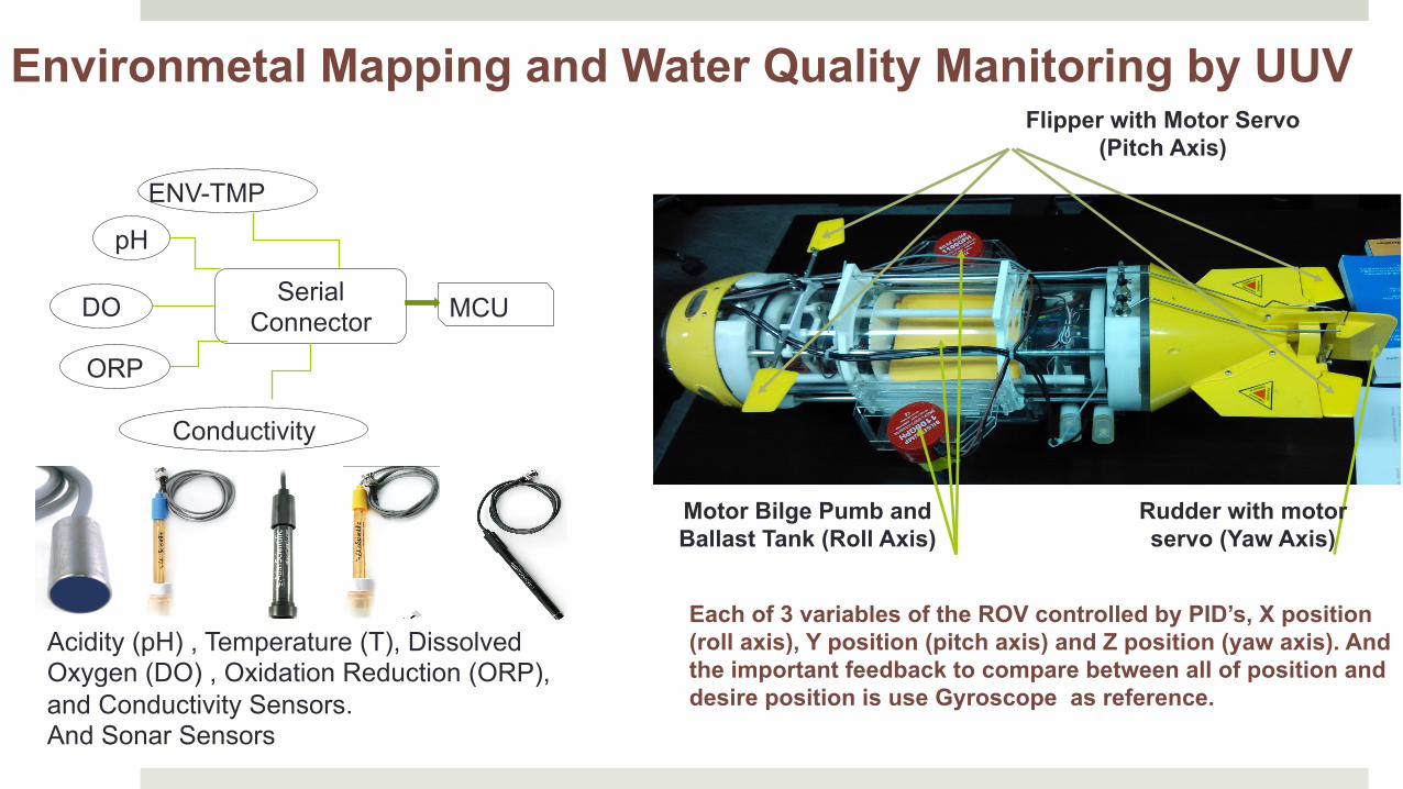
Flipper with Motor Servo (Pitch Axis)
Rudder with motor servo (Yaw Axis)
Motor Bilge Pumb and Ballast Tank (Roll Axis)
Environmetal Mapping and Water Quality Manitoring by UUV
Each of 3 variables of the ROV controlled by PID’s, X position (roll axis), Y position (pitch axis) and Z position (yaw axis). And the important feedback to compare between all of position and desire position is use Gyroscope as reference.
Conductivity
ENV-TMP
pH
Serial Connector MCU DO
ORP
Acidity (pH) , Temperature (T), Dissolved Oxygen (DO) , Oxidation Reduction (ORP), and Conductivity Sensors. And Sonar Sensors

