requirements specificatiow nickel cadmium battery … · 3.1.3 interface block diagram. the...
TRANSCRIPT

,. - -
c
V E R S I O N 1 MCR-86-674
R E Q U I R E M E N T S S P E C I F I C A T I O W
FOR
N I C K E L CADMIUM B A T T E R Y E X P E R T S Y S T E M
N A S 8 - 3 5 9 2 2
D E V E L O P E D F O R
N A S A / M A R S H A L L S P A C E F L I G H T C E N T E R
H U N T S V I L L E , ALABAMA
P R E P A R E D B Y
M A R T I N M A R I E T T A C O R P O R A T I O N
A E R O S P A C E D I V I S I O N
D E N V E R , COLORADO
S E P T E M B E R 1986
( N A S A - C R - 179034) B E Q D I R E l f E N l 3 SEECIPICATION FCP NICKEL CALHIUE EAP'IEBP EXEEEl SYSTEd (Eart in B a r i e t t a Aerospace) t? F CSCL 1OC
H07-2C473
Unclas 63/33 45236
https://ntrs.nasa.gov/search.jsp?R=19870011040 2020-03-23T02:42:14+00:00Z

.
TABLE OF CONTENTS
SECTION 1 . SCOPE ............................................... 1 1.1 Identification ......................................... 1 1.2 Functional Summary ..................................... 1
SECTION 2 . APPLICABLE DOCUMENTS ................................ 1
e
SECTION 3 . REQUIREMENTS ........................................ 1
3.1.1 System Capacities ................................ 3.1.2 Interface Requirements .......................... 2
3.1.2.1 Interface Block Diagram ..................- 3.2 Detailed Functional Requirements ....................... 2
3.2.1 Function Main ................................... 4 3.2.2 Function Initialization ......................... 5 3.2.3 Function Read-Data .............................. 6 3.2.4 Function Process-Data ........................... 7 3.2.5 Function Write-Files ........................... 10
3.2.7 Function Interrupt Handler ..................... 12
3.1 Computer Program Definition ............................ 1 9
3
3.1.2.2 Detailed Interface Definition ............ 2
3.2.6 Function Finish ................................ 11
3.2.8 Function PROLOG Initialization ................. 13 3.2.9 Function Start ................................. 14
3.2.11 Function Status ............................... 16 3.2.10 Function Fault-Diagnosis ...................... 13
3.2.12 Function Advice ............................... 18 3.2.13 Function Graphics ............................. 21
3.3 Special Requirements .................................... 3.3.1 Programming Methods . . . ...........................
- 9
3 3
3.3.2 Program Organization ........................... 22 3.3.3 Modification Consideration ..................... 22
3 3 3.3.4 Special Features ................................. 3.3.5 Expandability .................................. 2 2 3.3.6 Special Timing ................................. & -
3.5 Data Base Requirements ................................ 23
3 3
3.4 Human Performance ..................................... 2 2
3.5.1 Source and Types of Input ...................... 23 3.5.2 Destinations and Types of Output . . . . . . . . . . . . . . . 24 3.5.3 Internal Tables and Parameters . . . . . . . . . . . . . . . . . 24
3.6 Adaptation Requirements ............................... 24 3.7 Government-Furnished Property List .................... 24

c
TABLE OF CONTENTS CONTINUED
SECTION 4 . QUALITY ASSURANCE PROVISIONS . . . . . . . . . . . . . . . . . . . . . . . 2 4 3.1 Introduction and Definitions .......................... 2 3 4 . 2 Test Structure ........................................
4.2.1 Module/Unit Level Testing ...................... 25 '7 5 4.2.2 Subsystem Integration Testing . . . . . . . . . . . . . . . . . . - 3 4
4 . 2 . 3 System Integration Testing ..................... 25 4 . 2 . 4 System Demonstration ........................... 2.5
4 . 3 Testing Techniques .................................... 2 6 4.4 Test Documentation .................................... ~6
4.4.1 Documentation of Test Plan ..................... 26 4.4.2 Documentation of Test Procedures ............... 2 6
'9 7 4.4.3 Documentation of Test Report ...................- 4.5 Verification Cross-Reference Matrix . . . . . . . . . . . . . . . . . . . 27
SECTION 5 . PREPARATION FOR DELIVERY ........................... 28
APPENDIX A . HUBBLE SPACE TELESCOPE BATTERY TESTBED
APPENDIX B . NICKEL-CADMIUM BATTERIES 0 ILLUSTRATIONS
FIGURE 1 . NICBES FUNCTIONAL DIAGRAM ........................ 3 FIGURE 2 . SCHEMATIC DIAGRAM OF TESTBED. .................... A2
ii

AH1 AH0 BPRC ccc DOD EOC EOD EOF BPS EST MMDA MS FC NICBES sow SPA
GLOSSARY
- ampere hours in - ampere hours out - battery protection and reconditioning circuits - charge current controllers - depth of discharge - end of charge - end of discharge - end of file - electrical power system - Hubble Space Telescope - Martin Marietta Denver Aerospace - Marshall Space Flight Center - Nickel-Cadmium Battery Expert System - Statement of Work - solar panel array

SECTION 1. SCOPE
1.1 Identification. This part of the specification establishes the requirements for performance, design, test, and qualification of a computer p r o g r a m identified as NICBES - Nickel Cadmium Battery Expert System. This contract, NAS8-35922, is from Marshall Space Flight Center ( M S F C ) i n Huntsville, Alabama.
1.2 Functional Summary. The specific spacecraft power system configuration selected was the Hubble Space Telescope (HST) Electrical Power System (EPS) Testbed located at MSFC. A detailed model description of the energy storage components is given in Appendix A. Power for the HST comes from a system of 13 Solar Panel Arrays (SPAS) linked to 6 Nickel-Cadmium Batteries (discussed in Appendix B) which are connected to 3 Busses. An expert system, NICBES, will be developed at Martin Marietta Denver Aerospace (MSFC) to recognize a testbcd anomaly, identify the malfunctioning component and recommend 3 course of action. Besides fault diagnosis, NICBES will be able to evaluate battery status, give advice on battery status and provide decision support for the operator. Information for the Nickel-Cadmium batteries will be extracted through knowledge engineering utilizing the "Nickel Cadmium Battery experts" at MSFC who are involved with the HST EPS Tes tbed. Additional knowledge sources will be elicited from literature earches and personnel at MMDA who have had experience with the operation
Extensive telemetry of the testbed operating of these batteries. conditions will be relayed from a DEC LSI-11 through a RS232 to an IBM-PC AT. A Data-Handler will be implemented on the IBM-PC AT to monitor the data flow and to summarize and condense the telemetry in a manner determined by the needs of the Expert System. Its output will be data files for use by the Expert System whose responsibilities are those listed above. Due to the single tasking constraints of the IBM-PC AT, the two sections of NICBES will be run independently. NICBES will be installed and demonstrated at MSFC upon development completion. Verification will be done by Software Quality Assurance at MMDA.
.. SECTION 2. APPLICABLE DOCUMENTS Statement of Work (SOW) - Contract Number NAS8-35922. SAMSO Exhibit 73-3, Standard Engineering Practices for Computer Software
Modification X 4 , December 31, 1985.
Design and Development, October 6, 1973.
SECTION 3. REQUIREMENTS
3.1 COMPUTER PROGRAM DEFINITION. This section will describe the functional relationship between NICBES and the A S T EPS Testbed with which it will be running.
1

3.1.1 SYSTEM CAPACITIES. Telemetry from the HST battery testbed is sent from a DEC LSI-11 through an RS232 at 9600 baud to an IBM PC-AT every one minute. The Data-Handler will read the input data, 370 ASCII numbers, integer or 5 place floatlng point, and perform appropriate processing within the one minute t i m e frame. Unless a fault is detected, i t will continue this t a s k f o r 1 2 complete orbits, 96 minutes per orbit. List formated data files will be prepared f o r use by the Expert System. The Expert System portion of NICBES reads the data files and operates accordingly to give fault diagnosis, battery status and advise or decision support. The Expert System is an interactive system which runs at the direction of the user with no timing constraints except for fault diagnosis which must be given within 20 minutes of fault detection.
3.1.2 INTERFACE REQUIREMENTS. NICBES can be considered an add-on to the HST EPS Testbed System. In no way will i t impact the Testbed operation. NICBES will have two modes of operation. The Data-Handler, to be written in MICRO-SOFT C, will be responsible for reading, processing and writing summarized data output files derived from the HST EPS Testbed telemetry. The Expert System will be programmed in PROLOG and will perform the fault diagnosis along with the battery status, advice and decision support from information in the data files created by the Data-Handler. NICBES is connected to the Testbed by a RS232. The Expert System and the Data-Handler work independently. Print-outs can be obtained from the STAR-SD-15 Printer MSFC has acquired to support the IBM-PC AT.
3.1.3 INTERFACE BLOCK DIAGRAM. The Interface Block Diagram for HST EPS Testbed and NICBES is given in Figure 1.
3.1.2.2 DETAILED INTERFACE DEFINITION. Telemetry is sent from a DEC LSI-11 to an IBM-PC AT where the N I C B E S package resides. Refer to SECTION 3.5.1 for a detailed description of the telemetry format as well as the format for the data files created by the Data-Handler. An Interrupt Handler will be implemented to receive the incoming telemetry accurately. A computer operator starts and stops the Data-Handler after which the Expert System can be enacted. The Expert System utilizes the output data files from the Data-Handler for its analysis. The Expert System is totally interactive, driven by menus and user input. There is also an STAR-SD-15 Printer attached to the IBM-PC AT so that the user can get a hardcopy of any Expert System screens.
3.2 DETAILED FUNCTIONAL REQUIREMENTS. The following paragraphs will give the detailed functional requirements necessary to develop the computer program NICBES. Since NICBES is composed o f two main sections, the functional requirements will be given first for the Data-Handler and then for the Expert System.
2

NlCBES FUNCTIONAL DIAGRAM
A N D FILE SERVER
7 cy M cy cn Iy
I i FAULT DIAGNOSIS I
STATUS AND ADVICE DECISION SUPPORT -
I I i
ORAPHICS
I I DECLSI-11 I TELEMErRT
HUBBLE SPACE TELESCOPE ELECTRICAL POWER SYSlTl4l TESTBED:
SQLARPANELARRAYS NICKEL CADIUM BATTERIES BUSSES AND LOAD BANKS
FIGURE 1
OPERATOR
I PRINTER 1
3

3'.2.1 Function Main. Main is the driver for the Data-Handler. It calls routines to initialize, read data, process data, write data files and exit. A 1 1 header information as include file names, define statements, global StructurGs, matrices and arrays will reside in a single include file.
3.2.1.1 Inputs. Once the computer operator has started the Data-Handler and c h e c k e d to make sure telemetry is coming across the RS232, there are no further actions or inputs required.
3.2.1.2 Process inq. Main controls the calling sequence of all routines. It does little processing besides determining the current phase (charge or discharge) and keeping track of the orbits.
3.2.1.3 OUtDUtS. A message will be printed to the screen at the end of each orbit. Phase and orbit parameters will be passed to other routines.
4

r b
3.2.2 Function Initialization. Initialization sets up the data catching scheme which takes o v e r the I B M poling techniques and' replaces it with an interrupt handler which takes incoming data and puts it in a buffer for program access.
3.2.2.1 Inputs. There are no inputs.
3.2.2.2 Processing. The communication port is set. The globally defined matrices and arrays used for processing are initialized. Telemetry is read until the start of an orbit is reached signaling the true start of the Data-Handler. . A n orbit starts at night minute 1 of the discharge phase and ends after the charge phase.)
3.2.2.3 OUtPUtS. A message is printed when the orbit start is found.
5

3 . 2 . 3 Function Read Data. Telemetry comes in from the DEC LSI-11 every one minute. Read data retrieves the telemetry from the interrupt handler buffer -- 370 vaiues, preceded by an ' A ' to indicate the beginning of the data.
3 . 2 . 3 . 1 Inputs. The interrupt handler buffer is accessed to read the telemetry input.
3 . 2 . 3 . 2 Processinc. The telemetry is read character by character from the interrupt handler buffer into 3 interim buffer and then put into a globally defined structured array using a 'sscanf' command. Telemetry reading wili be synchronized with the character ' A ' signalling the start of the data stream. Telemetry is read in groups. First the header information as date, orbit, phase, etc. Then data for each of the six batteries is read. Last is solar panel array (SPA) and bus data. Each line of telemetry has an associated value, new line and carriage return. If an E O F (end-of-file) is encountered while reading telemetry error checking will be activated. No communication will also alert an error checking process. In addition, as telemetry is received, fault checking will be done against ranges specified in Section 3.2.9, unless it is decided that a fault signal will be sent from the DEC LSI-11.
3 . 2 . 3 . 3 Outputs. Telemetry is stored in a globally defined structured array (containing all 3 7 0 data points) for the next stage of processing. The structured array will have two columns, one for the last set of telemetry and one for the current set. Error messages for communication problems will be written t o the screen.
6

3.2.4 Function Process Data. Telemetry needs to be summarized and condensed. Process data takes data stored in the globally defined structured array, performs mathematical operations and keeps the results in globally defined buffers until i t is time to write them to data files. Some stored values are the result of an entire orbit's data while other values are derived and written to o u t p u t files every minute.
3.2.4.1 Inputs. Telemetry which has been stored in the globally defined structured array will serve a s input.
3.2.4.2 Processing. Telemetry is processed by keeping running sums, maximums, minimums and averages. There are three cases f o r processing: End of Charge (EOC), End of Discharge (BOD) and Every Minute. The processed data will be written to files at the appropriate times. Information needed includes EOD battery voltage, high battery voltage during charge, recharge r3ti0, EOD cell voltages, cell voltages at high point during charge, average battery temperatures, time on trickle charge, current during' reconditioning, cell pressure at one-minute intervals during last charge, cell voltages, AH1 and AHO, current from each of the SPAs and the three busses, and orbit number. For most of these parameters, values will be kept for the last 12 orbits, based upon an "expert's opiniont' that enough data could be collected for confident decision making. Following is a synopsis of what processing needs to be done for each data file.
Fault file - Contains a fault flag = 1 if there was a fault = 0 if no fault was detected.
Current file 1 - Contains the current orbit number and a reconditioning flag f o r each battery
= 1 for reconditioning = 0 no reconditioning.
Current file 2 - Contains Phase (charge or discharge) Day-min Current from 13 SPAs (Solar Panel Array) Voltage from 3 Busses Average Temperature per Battery (6)
Current file 3 - Contains Battery Cell Voltages (23 per battery)
7

.-
Each o f t h e f o l l o w i n g Data f i l e s h a s 6 rows o f d a t a , o n e f o r e a c h b a t t e r y . I n many o f t h e Data f i l e s t h e r e are 1 2 c o l u m n s , o n e for e a c h o r b i t . They a r e l i s t e d i n c h r o n o l o g i c a l o r d e r .
Data f i l e 1 (.6x12) - F i l e c o n t a i n s b a t t e r y v o l t a g e t a k e n a t E O D p e r o r b i t f o r l a s t 1 2 o r b i t s .
Data f i l e 2 ( 6 x 1 2 ) - F i l e c o n t a i n s t h e b a t t e r y v o l t a g e a t h i g h i n - c h a r g e f o r t h e l a s t 1 2 o r b i t s . T h e r e a r e 23 c e l l s p e r b a t t e r y . ( N o t e 1 )
Data f i l e 3 ( 6 x 1 2 ) - F i l e c o n t a i n s t h e r e c h a r g e r a t i o = XHO/AHI p e r o r b i t for 1 2 o r b i t s . ( N o t e 2 )
Data f i l e 4 ( 6 x 3 6 ) - F i l e c o n t a i n s c e l l v o l t a g e s a t E O D , w i t h t h e h i g h v a l u e , low v a l u e a n d a v e r a g e o f a l l v a l u e s , i n t h i s o r d e r p e r o r b i t f o r t h e l a s t 1 2 o r b i t s . So a row c o n t a i n s 1 2 h i g h v a l u e s , 1 2 low v a l u e s and t h e n 1 2 a v e r a g e v a l u e s .
Data f i l e 5 (6x36) - F i l e c o n t a i n s c e l l v o l t a g e s a t h i g h - c h a r g e ; h i g h , low a n d a v e r a g e o f a l l v a l u e s , in t h i s o r d e r , p e r o r b i t for l a s t 1 2 o r b i t s . Each row c o n t a i n s 1 2 h i g h v a l u e s , 12 l o w v a l u e s a n d t h e 1 2 a v e r a g e v a l u e s . ( N o t e l j
Data f i l e 6 ( 6 x 2 3 ) - F i l e c o n t a i n s 2 3 c e l l v o l t a g e s a t EOD f o r e a c h b a t t e r y , f r o m t h e l a t e s t o r b i t .
Data f i l e 7 ( 6 x 2 3 1 - F i l e c o n t a i n s 2 3 c e l l v o l t a g e s a t h i g h - c h a r g e f o r the l a t e s t o r b i t .
0
Data f i l e 8 ( 6 x 4 8 ) - F i l e c o n t a i n s t h e a v e r a g e o f t h e s i x t e m p e r a t u r e s e n s o r s ( d e g r e e s C) p e r b a t t e r y , a t two m i n u t e i n t e r v a l s ( l m i n , 3 m i n , ... 9 5 m i n ) o v e r t h e l a t e s t o r b i t .
Data f i l e 9 ( 6 x 1 2 ) - F i l e c o n t a i n s t h e a v e r a g e b a t t e r y t e m p e r a t u r e s p e r o r b i t f o r t h e l a s t 1 2 o r b i t s . T h i s i s t h e a v e r a g e o f t h e t e m p e r a t u r e a v e r a g e s i n Data f i l e 8 .
Data f i l e 1 0 ( 6 x 4 6 ) - F i l e c o n t a i n s t h e 2 3 c e l l p r e s s u r e s t a k e n a t E O C and t h e n t h e 2 3 c e l l p r e s s u r e s t a k e n a t EOD f o r e a c h b a t t e r y i n t h e l a s t f u l l o r b i t .
Data f i l e 11 ( 6 x 1 2 ) - F i l e c o n t a i n s t h e t i m e on t r i c k l e c h a r g e for e a c h b a t t e r y p e r o r b i t f o r t h e l a s t 1 2 o r b i t s . ( N o t e 3 )
8

. -
Data file 12 ( 6 x 4 9 ) - File contains battery current during reconditioning, at 2-minute intervals, for last reconditioning of each battery. I t is recorded every 2 minutes, only when battery reconditioning flag is 1 and only for one orbit. Column 1 contains t h e . orbit number for which reconditioning is occurring. The file contains zeroes until 3 battery is reconditioned.
Data file 13 - File contains AH0 summed over discharge phose per o r b i t for last 12 orbits. (Note 2 )
Note 1--look for highest voltage of any of the 23 cells in a battery. Compare incoming values to i t , keeping the highest, until phase changes to 0. This is used in Data files 2, 5 and 7.
Note 2--recharge ratio is AHO/AHI. Keep running sum of AH0 when phase is 0, and running sum of AH1 when phase is 1, using battery current. Figure recharge ratio at EOC (phase goes to 0). Used in Data files 3 and 13.
Note 3--during charge phase, when battery current drops to a low value, start counting trickle charge time. Keep increrenting this count each minute, until phase goes to 0.
Note 4--An orbit starts with discharge phase (0), night minute = 1. Charge phase (1) follows, counted by day minutes. There are 96 minutes in one orbit. EOC means End of Charge and EOD means End of Discharge.
0 3.2.4.3 Outputs. Output will be stored in the form of globally defined matrices and arrays to keep track of the required processed data. Most of these buffers record data over a period of twelve orbits. For the more orbits n recycling process is required, i.e., the first column is dropped, the others 3re moved to the left one column and the latest orbital d a t a values are put in the 12th column. In this manner only the latest 12 orbits a r e kept.
9

3.2.5 Function Write Files. Processed data is written to f i l e s , some every one or two minutes, others at EOC and EOD per orbit. The processed data has been stored in various globally defined matrices and arrays. There are seventeen output f i l i t s which are written to at designated times.
3.2.5.1 Inputs. Summarized and condensed data stored in matrices and arrays will s e r v e as input.
3.2.5.2 Processing. The processed data buffers will be written to Data files and Current files in list format. The Fault file will be written initially with fault flag = 0. It will be changed only when a fault is detected. The Data files will contain a main list composed of 6 sublists, one for each battery. These sublists c o n t a i n the required values followed b y commas and enclosed in brackets. An identifier is placed at the beginning of each file consisting of the name of the file and an associated number. For example, Data file 1:
show(l,[[al,bl,cl,dl,el,fl,gl,hl,il,jl,kl,ll], [a2,b2,cZ,dZ,e2,fZ,gZ, . . . . . . . . . . . . . . I , [a3, ................................ 1 , [a4, ................................ 1 , [as, . . . . . . . . . . . . . . . . . . . . . . . . . . . . . . . . I , [as, . . . . . . . . . . . . . . . . . . . . . . . . . . . . . . . . ] j ) .
In this example there are 12 columns, one per orbit. Orbital data is listed in chronological order.
An example of a Current file is given below: curf(Z,[Phase,Day-min,[SPA currents],[Bus voltages],[Battery Temps];).
3.2.5.3 OUtRUtS. The following output files are written At EOC:
Data file 2 Data file 3 Data file 5 Data file 7 Data file 8 Data file 9 Data file 11 Data file 12
Current file 1 Current file 2 Current file 3
Every Minute:
10
At EOC: Data file 1 Data file 4 Data file 6 Data file 10 Data file 13
When a fault is detected: Fault file

3.2.6 . F u n c t i o n F i n i s h . F i n i s h w i l l s e r v e a s t h e e x i t i n g module f o r t h e D a t a - H a n d l e r .
3.2.6.1 I n p u t s . When t h e D a t a - H a n d l e r h a s c o m p l e t e d i t s f u n c t i o n , t h e o p e r a t o r i n p u t s ;I
’ “ C ’ t o h a l t p r o c e s s i n g . E x i t i n g c a n also o c c u r a f t e r read errors w h i c h t h e D a t a - H a n d l e r deems very serious o r when a f a u l t i s d e t e c t e d . .
3.2.6.2 P r o c e s s i n g . T h e r e i s no p r o c e s s i n g d o n e i n F i n i s h e x c e p t t o c a l l f u n c t i o n s t o w r i t e f i n a l d a t a f i l e s .
3.2.6.3 O u t p u t s . A m e s s a g e w i l l b e p r i n t e d t o t h e s c r e e n s a y i n g t h a t t h e D a t a - H a n d l e r i s e x i t i n g .
11

3 . 2 . 7 Function Interuut Handler. The Interupt Handler will take over control of the standard IBM poLing techniques to read telemetry bursts coming from the DEC LSI-11 via 8 RS232. This is required to ensure the validity of the passed data s t re , im;
3.2.7.1 Inputs. Telemetry from the HST EPS Testbed.
3.2.7.2 Processing. The Interupt Handler will pick up each character from the communication network and place i t in a circular buffer which can then be a c c e s s e d by the Data-Handler programs. Write and read pointers will keep track J C information position in the buffer. An E O F designates no data.
3.2.7.3 OUtRUtS. Output will be a buffer in which telemetry characters have been stored.
12

3 . 2 . 8 F u n c t i o n PROLOG i n i t i a l i z a t i o n . T h i s program i s a u t o m a t i c a l l y e x e c u t e d whenever P R O L O G i s called. I t w i l l b e u s e d t o l o a d a l l t h e P R O L O G programs f o r t h e E x p e r t S y s t e m , c o p y a n d l o a d a l l n e c e s s a r y d a t a f i l e s , and s t a r t up t h e E x p e r t S y s t e m .
3 . 2 . 8 . 1 I n p u t s . Yo i n p u t s .
3 . 2 . 8 . 2 P r o c e s s i n g . Loads P R O L O G programs and d a t a f i l e s , and t h e n e x e c u t e s t h e Exper t System.
3 . 2 . 8 . 3 O u t p u t s . No o u t p u t s .
13

3.2.9 Function Start. This is the main driver for the Expert System. It is written in P r o l o g . Start calls all the other Prolog programs-and a l s o displays all the menus for the user interface. The Fault Diagnosis routine is c a l l e d automatically if a fault has been detected. The other routines are callrd when the user selects them from the menus.
3.2.9.1 Inputs. There are two input files: Fault file - Contains a fault flag = 1 if there was a fault
= 0 if no fault was detected.
Current file 1 - Contains the current orbit number and a reconditioning flag for each battery
= 1 for reconditioning = 0 no reconditioning.
The remaining inputs to this program involve user selections to menus.
3.2.9.2 ProcessinK. Start checks the fault flag and brings up Fault Diagnosis if a fault was detected. It then directs the system flow according to user selection-to menus. They pick which section to view from a choice of Graphics, Battery Status and/or Advice. e 3.2.9.3 Outputs. There will be four menus written to the screen to enable the user t o easily traverse within the Expert System. They are:
Main Menu - 1. Graphics - Decision Support 2. Battery Status 3. Battery Advice. 4. Quit
Battery Selection - select Battery 1 to 6.
Graphics Menu - choice of 12 plots for each battery, corresponding to Data files 1 to 12.
Advice Menu - 1. Recondition the battery? 2. Change the workload? 3. Change the charging scheme?
After 3 selection is made from the Main Menu, a particular battery is chosen before Graphics, Battery Status or Battery Advice is called. U p o n completion, another battery may be chosen for viewing with respect t o the Main Menu selection or. the user can return to the Main Menu.
14

3.2.10 Function Fault Diagnosis. This module performs Fault Diagnosis which is called if the fault f l a g = 1. Telemetry from the HST Testbed indicating a serious malfunction will cause an alarm to be sent t o the engineer and a shut down of t h e s y s t e m . There are five categories that will trigger this action. They are: 1.
3 -.
3 .
4 .
5 .
Power Supplies a. SPA current < 5 amps during first 5 minutes of charge p h a s e . b. SPA current > = 8 amps for 1-SPAS (1,3,5,7,9,11).
c. SPA current > 5 amps during discharge phase. SPA current > = 16 amps for 2-SPAS (2,4,6,8,10,12,13).
Batteries a. Cell voltage < = 0 volts for any cell in any battery. b. Cell voltage > 1.55 volts for any cell in any battery.
Load Banks a . Sum of 3 bus currents > 99 amps. b. Load < 5 amps on any single bus during discharge phase.
Temperature a. Average of the 6 temperature sensors > 25 C or i -10 C.
Communication a. Missing 3 consecutive telemetry bursts.
3.2.10.1 Inputs. a
Two current data files are input: Current file 2 - Contains Phase (charge or discharge)
Day-min Current from 13 SPAS (Solar Panel Array! Voltage from 3 Busses Average Temperature per Battery ( 6 )
Current file 3 - Contains Battery Cell Voltages (23 per battery)
3.2.10.4 Processing. Each of the above five fault conditions is checked individually comparing the current data files against the expected data values as predetermined by MSFC.
3.2.10.3 Outuuts. Header is displayed, 'FAULT DIAGNOSIS FOR ORBIT # ' . One or more of the above five fault conditions is reported as the source(s) of the fault, along with the malfunctioning component and if possible its value. F o r example: Hard Short in cell 3 of battery 1, or
Load on Bus 3 < 5 A, load bank error.
15

:3.2.11 Function Status. The Status portion of the Expert System checks the selected battery f o r reconditioning, temperature, workload, charging scheme and divergence.
3.2.11.1 Inputs. Data files are used as input.
Data file 1 - File contains battery voltage at EOD for last 12 orbits, in chronological order.
Data file 2 - File contains the battery voltage during high in-charge for last 12 orbits.
Data file 3 - File contains the recharge ratio = AHO/AHI per orbit for 12 orbits.
Data file 4 - File contains cell voltages at EOD, with the high value, Low value and average of all values, in this order for each of the last 12 orbits
Data file 8 - File contains the averages of the six temperature sensors (degrees C ) , at two minute intervals over the latest orbit.
Data file 9 - File contains the average battery temperatures over entire orbit for the last 12 orbits.
Data file 13 - File contains AH0 summed over discharge phase per o r b i t . : for last 12 orbits.
3.2.11.2 Processing. First check to see if the selected battery is being reconditioned. If s o , stop this process since data will be misleading. Otherwise, f o u r procedures are called to check selected battery performance. Averages (battery data averaged over 12 orbits) are used for the status analysis.
COND IT I O N Temperature check (Data files 8 and 9 )
Temperature average over last orbit < 0 and over last 12 orbits < 0
Temperature average over last orbit > 11 and over last 12 orbits > 10
Temperature average over last orbit > 11 and o v e r last 12 orbits < 10
STATUS
= > C o l d
= > Hot or possible overcharging
= > Possible overcharging
16
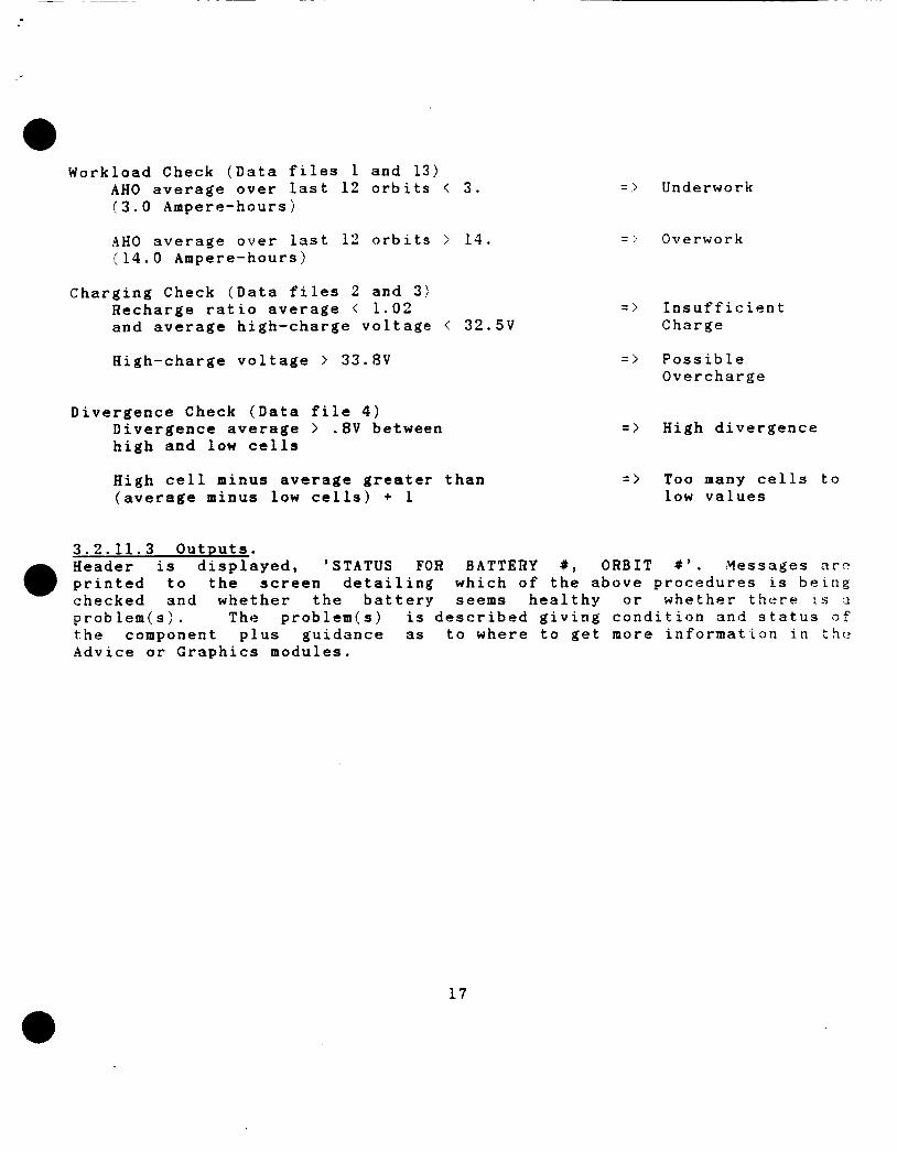
W o r k l o a d Check (Data f i l e s 1 a n d 1 3 ) A H 0 a v e r a g e o v e r l a s t 1 2 o r b i t s < 3. (3.0 Ampere -hour s )
-4HO a v e r a g e o v e r l a s t 12 o r b i t s > 1 4 . .: 1 4 . 0 Ampere -hour s )
= ) Underwork
- '. Overwork
C h a r g i n g Check ( D a t a f i l e s 2 and 3) R e c h a r g e r a t i o a v e r a g e < 1 . 0 2 = > I n s u f f i c i e n t a n d a v e r a g e h i g h - c h a r g e v o l t a g e < 32.5V Charge
H i g h - c h a r g e v o l t a g e > 33.8V
D i v e r g e n c e Check ( D a t a f i l e 4 ) D i v e r g e n c e a v e r a g e > .8V b e t w e e n h i g h and low c e l l s
H i g h c e l l minus a v e r a g e g r e a t e r t h a n ( a v e r a g e m i n u s low c e l l s ) + 1
= > P o s s i b l e O v e r c h a r g e
= > H i g h d i v e r g e n c e
= > Too many c e l l s t o low v a l u e s
3 . 2 . 1 1 . 3 O U t R U t S . Header i s d i s p l a y e d , 'STATUS FOR BATTERY #, O R B I T # ' . M e s s a g e s arc) p r i n t e d t o t h e s c r e e n d e t a i l i n g w h i c h o f t h e a b o v e p r o c e d u r e s i s b e i n g c h e c k e d a n d w h e t h e r t h e b a t t e r y seems h e a l t h y o r w h e t h e r t h e r e L S a p r o b l e m ( s ) . The p r o b l e m ( s ) i s d e s c r i b e d g i v i n g c o n d i t i o n a n d s t a t u s o f the componen t p l u s g u i d a n c e 3s t o w h e r e t o g e t more i n f o r m a t i o n i n t h c A d v i c e o r G r a p h i c s m o d u l e s .
17

i
3 . 2 . 1 2 Function Advice. The Advice section goes into' further detail than the Status section on three subjects: whether a battery needs reconditioning, c h a n g e s ~n charging scheme, or changes in its workload.
3 . 2 . 1 2 . 1 Inputs. Inputs will be in the form of data files which will have been c r e a t e d h v the Data-Handler. They are: Data file 1 - File contains battery voltage at EOD for last 1 2 orbits, in chronological order.
Data file 2 - File contains the battery voltages during high in-charse period for each of the last 12 orbits.
Data file 3 - File contains the recharge ratio = AHO/AHI per orbit for 1 2 orbits.
Data file 4 - File contains cell voltages at EOD, with the high value, ? n u value and average of all values, in this order for each of the Last 1'1 orbits
Data file 9 - File contains the'average battery temperatures over entire orbits f o r the last 12 orbits.
Data file 10 - File contains the 23 cell pressures token at EOC and t h e r . EOD for each battery in the last f u l l orbit.
Data file 13 - File contains AH0 summed over discharge phase, per n r - b i t for last 1 2 orbits.
3 . 2 . 1 2 . 2 Processing. Trend analysis and averaging calculations will be performed for t h e following parameters, data read from the above data files:
Recondit ioninq Charging Scheme Workload EOD batt voltage in-charge high voltage EOD batt voltage in-charge high voltage recharge ratio EOD cell diverge recharge ratio temperature Avg AH0 EOD cell divergence Avg in-charge cell diverge in-charge cell divergence Avg EOD cell pressure
Avg EOC cell pressure
Trends will be expressed as none, slightly-up, up, strongly up, slightly-down, down and strongly down. Trends will be calculated by using two simple mathematical functions. They can be expressed as:
n - - n-1 n - 1. 2 - X(ij 2 . - i t X(i)
i=l i= 1 where i < = 1 to 12 orbits and X(i> are the associated parameters.
18

The difference between the weighting functions is taken and then compared to hand crafted deviation factors to determine the trends. The first function weights all parameter values for a battery equally, while the second function weights the recent parameter values more heavily. For a list of constant values, the two functions ore equal. Divergence is simply computed b y taking the differences between corresponding values of two lists as high-voltage cells and low-voltage cells.
For reconditioning, 11 conditions need to be checked for 3 particular battery: 1. EOD voltage strongly down, in-charge divergence strongly up = )
2. EOD voltage strongly down, in-charge voltage strongly down = )
3. EOD divergence strongly up, in-charge divergence strongly up = ?
3 . Voltage trends strongly down or down, recharge ratio and divergence
reconditioning advised.
recondition soon.
strongly rising divergence indicates reconditioning.
trends strongly up or up = > reconditioning is indicated by all 5 trends.
5. Recharge ratio strongly up = > reconditioning indicated. 6. In-charge voltage is down or strongly down, in-charge divergence
is up or strongly up = > reconditioning recommended. 7. EOD voltage down or strongly down, in-charge divergence up or
strongly up = > reconditioning indicated. 8. EOD and in-charge divergence both up = > consider reconditioning. 9. Recharge ratio up = > consider reconditioning. 10. Both EOD and in-charge voltages down = > consider reconditioning. 11. None of the above = ? no need for reconditioning at present.
To determine if the charging scheme for a battery should be changed, nine conditions are checked: 1. Temperature strongly up, EOD pressure greater than 120, EOC pressure
2. In-charge voltage strongly up = > check f o r overcharging. 3. EOD pressure greater than 110, EOC pressure greater than 135 = >
4. EOD voltage strongly down, in-charge voltage strongly down = >
5. EOD voltage down, in-charge voltage down = > undercharging. 6. EOD voltage strongly down or down, in-charge voltage strongly down
or down = > undercharging may be causing loss of voltage. 7. EOD voltage down, in-charge divergence greater than .8 = ?
undercharging may be causing l o s s of voltage. 8. EOD voltage strongly down, in-charge divergence greater than . 8
= > undercharging may be causing serious loss of voltage. 9. None of the above = > no need to change charging scheme.
greater than 140 = > overcharging causing high pressure.
charge rate may be too high.
undercharging may be seriously affecting capacity.
19

Six conditions are checked to advise as to battery workload change: 1. E O D voltage down, EOD divergence down, A H 0 average less than 25 = .
2. E O D voltage strongly down, EOD divergence strongly down, .\HO average loads probably too light.
lass than 5 = > losing capacity due to memory effect, try heavier load.
3. AH0 average greater than 14 =') possibly destructive overwork. 4. A H 0 average greater than 9 = i heavy workload. 5. E O D voltage down or stongly down, EOD divergence down or strongly
down, A H 0 average above 6 = > losing capacity, consider reconditioning.
6. Yone of the above = > no need to change workload.
3.2.12.3 Outputs. A header is displayed, 'ADVICE FOR B A T T E R Y #, O R B I T t ' . Messages are - .
printed to the screen detailing which of the three choices is b e i n g examined and what the trends are for 3 particular battery. Given the condition, corrective action is recommended as reconditioning the battery, changing the workload or changing the charging scheme along with an explanation. Support of these decisions can be gotten from by viewing the plots detailed in the next section..
20

3 . 2 . 1 3 F u n c t i o n G r a p h i c s . G r a p h i c s s u p p l y t h e u s e r w i t h d e c i s i o n s u p p o r t i n t h e f o r m o f 1 2 p l o t s a n d h i s t o g r a m s f o r 3 s e l e c t e d b a t t e r y .
3 . 2 . 1 3 . 1 I n p u t s . G r a p h i c s u s e s Data f i l e ( i ) ( i = 1 t o 1 2 ) a s i n p u t s . O t h e r i n p u t c o m e s f r o m u s e r menu s e l e c t i o n s w h i c h d e t e r m i n e w h i c h o f t h e 1 2 g r a p h s t o p l o t a n d f o r w h i c h b a t t e r y .
3 . 2 . 1 3 . 2 P r o c e s s i n g . The a p p r o p r i a t e d a t a f i l e is read t o g e t t h e d a t a f o r t h e selected b a t t e r y . G r a p h i c s p r i m i t i v e s a r e u s e d d r a w c o l o r p l o t s o f t h e d a t a . T i t l e s , v e r t i c a l a n d h o r i z o n t a l c a p t i o n s a r e p r i n t e d a l o n g w i t h b a t t e r y number a n d c u r r e n t o r b i t . The l i s t s o f da t a a re t h e n p l o t t e d , p o i n t b y p o i n t .
3 . 2 . 1 3 . 3 O u t p u t s . O u t p u t c o n s i s t s o f 1 2 p l o t s for any b a t t e r y (1-6) c o r r e s p o n d i n g t o the 1 2 Data f i l e s .
1. 2 . 3. 4 . 5 . 6 . 7. 8. 9 .
LO. 11. 1 2 .
The u s e r s c r e e n .
B a t t e r y V o l t a g e a t EOD for l a s t 1 2 o r b i t s B a t t e r y V o l t a g e a t h i g h i n - c h a r g e for l a s t 1 2 o r b i t s R e c h a r g e r a t i o for l a s t 1 2 o r b i t s C e l l V o l t a g e s a t EOD; h i g h , l o w , a v e r a g e for l a s t 12 o r b i t s C e l l V o l t a g e s a t h i g h i n - c h a r g e ; h i g h , l o w , a v g , l a s t 1 2 o r b i t s C e l l V o l t a g e s a t EOD for l a t e s t o r b i t C e l l V o l t a g e s a t h i g h i n - c h a r g e f o r l a t e s t o r b i t A v e r a g e B a t t e r y T e m p e r a t u r e f o r l a t e s t o r b i t , e a c h 2 m i n A v e r a g e B a t t e r y T e m p e r a t u r e for l a s t 1 2 o r b i t s C e l l P r e s s u r e s a t EOC and BOD for l a t e s t o r b i t T i m e o n T r i c k l e C h a r g e f o r l a s t 1 2 o r b i t s B a t t e r y C u r r e n t d u r i n g r e c o n d i t i o n i n g , 1 o r b i t , e a c h 2 m i n
w i l l b e a b l e t o get a h a r d c o p y of t h e p l o t as d i s p l a y e d o n t h e
2 1

3 . 3 Special Requirements. The following paragraphs will give a description of the special requirements which will affect the design of N I C B E S .
3.3.1 Prop-ramming Method(s1. Structured Programming methods will be applied to the 'C' routines in t h e Data-Handler. The Expert System routines will be written in Prolog w h i c h is 3 logic programming language. Although the Expert System can not follow structured programming techniques due to its inherent qualities, it will be modular and somewhat procedural.
3.3.2 Program Organization. The Data-Handler and the Expert System will be built as two separate systems whose only dependencies are the data files.
3.3.3 Modification Consideration. There will be no allowable modifications during operation of the D a t a- Hand 1 er . The Expert System will allow adjusting of the deviation factors and ranges of the plots. These modifications must be made prior to running the Expert System.
3.3.4 Special Features. Print statements to facilitate the testing of the Data-Handler will D e 0 left in the programs, but commented out for actual system execution. 3.3.5 Expandabi li ty. Due to the moderate size of N I C B E S , there is adequate room for expansion. However true expansion to its function would best be done o n a multi-tasking computer.
3.3.6 Special Timing. Since the Data-Handler and the Expert System will be developed and testeci independently, there are no special timing requirements.
3 . 4 Human Performance. The Expert System will be an entirely interactive system whereby the user will make selections from menus to direct the type of information desired. The menus are described in Section 3.2.8.3. Responses to menus will usually be item number selection. Response checking will occur a f t e r each user entry. There are no time or order constraints imposed u p o n user input. Displays will remain on the screen until the user opts to continue.
2 2

a 3.5 Data Base Requirements. HICBES is a data driven model. In the following paragraphs exact d a t a base requirements will be listed.
3.5.1 Sources and Tvpes of Input. Input to the Data-Handler is in the form of telemetry bursts, i?ar:h containing 3 7 0 values - one per line, routed from the DEC L S I - 1 1 t o t h e IBM-PC AT every one minute. Following is the format:
Start of Telemetry Burst A
Header Information (Integer) year day of year - 198X hour - 0 to 24 minute - 0 to 60 second - 0 to 60 orbit - Positive Integer phase - 0 for discharge, 1 for charge day minute (minute in charge) - 0 to 70 night minute (minute in discharge) - 0 to 37
Batterv Information (for each of 6 batteries) battery number cell voltage cell pressure battery voltage battery current
bprc current temperature sensors battery reconditioning
Yiscellaneous Information Solar Array current Bus Voltage Bus current
Integer 1 - 6 23 Reals -2 to + 2 volts 23 Integers 0 to 150 psi Real 0 to 40 volts Real -30 to +25 amps
negative for discharge p h a s e positive for charge phase
Real 0 to 5 amps 6 Reals -15 to 30 (degrees C ) Integer 0 for no, 1 f o r yes
13 Reals 0 to 20 amps 3 Reals 0 to 40 volts 3 Reals 0 to 90 amps
Reals are five place floating point numbers.
Inputs to the Expert System are the data file outputs of the Data-Handler, see Section 3.24 for a complete description. A l l other inputs to the Expert System are user selections to menus.
23

3.S.2 Destination and Types of Outputs. Output from the Data-Handler is in the form of data files which will be used as input to the Expert System. Al l the battery data files and their format are listed under section 3 . 2 . 4 . 2 . Output from the Expert System is in the form of reports, explanations, analysis and graphs. Xo data files are created.
3.5.3 Internal Tables and Parameters. Global structures and parameters for the Data-Handler will b e set-up .in an include file. All parameters in the Expert System will be passed to functions as needed, i.e., no global parameters.
3.6 Adaptation Requirements. NICBRS will be written specifically for analysis in support of the Hubble Space Telescope Testbed. Adaptations to other EPSs will require seperate efforts, although the concepts may remain the same.
3.7 Government-Furnished Property List. Xo Government property will be used in the development of NICBES. However the following hardware and software are required at Marshall Space Flight Center for NICBES installation and demonstration:
Hardware Software DEC LSI-11 MICROSOFT C IBM-PC AT ARITY PROLOG Version 4.1 STAR-SD-15 Printer RS232
SECTION 4 . QUALITY ASSURANCE PROVISIONS
4.1 Introduction and Definitions. In order to assure functionality and accuracy of NICBES several types of testing will be conducted. All testing will be conducted during development at MMDA. The final system installation and demonstration will be performed at MSFC at the time of delivery.
4.2 Testing Structure. The test program will be structured into the following four levels g f testing.
24

4 . 2 . 1 Module/Unit Testing. Module/Unit tests are the first informal tests which will be conducted b y the programmer prior to establishment of the test baseline. Moduleiunit testing will demonstrate the accuracy of the operations indicated in t h e functional requirements, Section 3 . 2 . Each moduleiunit will be tested using nominal, extreme and erroneous input values and will be t e s t e d f :>r error detection and proper error recovery including appropriate error messages. Each decision option will be exercised to execute subordinate units performing input or output functions.
3 . 2 . 2 Subsystem Integration Testing. Subsystem integration tests are the final informal tests conducted by the
Subsys tern programmer prior to establishment of the test baseline. integration testing will demonstrate the accurate implementaion of interfaces between module/units. As each module/unit is integrated into the subsystem, the interface will be tested using nominal, extreme a n d erroneous input values and will be tested for error detection and proper error recovery including appropriate error messages. There are only two subsystems f o r NICBES, the Data-Handler and the Expert System Interface.
4.2.3 System Integration Testing. System integration tests are the formal tests conducted by the programmer after establishment of the formal baseline. System integration testing will demonstrate the accurate implementation of interfaces between subsystems. As each subsystem is integrated into the system the interface will be tested f o r error detection and proper error recovery including appropriate error messages. The system size/memory requirements and execution time will be measured and evaluated. An integrated system t e s t will be conducted to verify required performance. F o r the NICBES system integration test the Data-Handler will be evaluated with telemetry obtained from MSFC HST EPS Testbed over modems. This data will then be used to simulate the data communication network at MSFC b y linking two LBM-PCs via a RS232 and transferring data at one minute intervals. The data files generated by the Data-Handler will then be used to evaluate the Expert System.
4.2.4 System Demonstration. -4 demonstration based on the integrated system test will be conducted at Marshall Space Flight Center upon delivery and installation of the software.
25

4.3 Testing Techniques. Testing will incorporate two fundamental methodologies.
4.3.1 Structure-Based Path Testing.
objective of path testing is to exercise enough differnet paths through the logic structure of a module/unit to demonstrate the accuracy o f t ! ia processing performed on the data. A path equates to an executable instruction sequence that starts at a module/unit’s entrance and e n d s at: its exit and may consist of one or more of the operations identified in the functional requirements, Section 3.2. Enough paths are required t : ~ ensure that every instruction in the module/unit has been exercised c t least once and every decision has been executed in each posssible direction at least once.
Path testing will be employed for module/unit level t - e s t i n p ; . .?he
4.3.2 Top-Down Integration. Top-down integration will be employed for both subsystem integration and system integration levels of testing. The objective of top-down integration is to build a string of modules from the executive or control module. Modules will be added to the string in increments to allow testing of individual interfaces. Modules not yet integrated a r e simulated by stub routines as integration progresses by adding individual modules and testing each interface.
0 4.3 Test Documentation. Test documentation will be written in the Test Plan, Test Procedures a n d Test Report.
4.4.1 Documentation of Test Plan. Test implementation information will be stated in the test plan and wiil specify the following:
1. Facility resources and location. 2. Schedule. 3. Manning requirements. 4. Preparation of input data. 5. Software configuration. 6. Organization of test operations. 6. Output analysis techniques.
4.4.2 Documentation of Test Procedures. h Test Procedures document will be written to accompany the Test Plan. It will reflect the following:
1. Program initialization instructions. 2. Operater interfaces. 3 . Input Data; 4. Required operator responses. 5. Test event sequence. 6. Information recording requirements. 7. Program termination/restart instructions.
26

4.4.3 Documentation of Test Reports. A Test Reports document will be written to accompany the Test Plan and Procedures. This document will relect the following information:
1. Actual test results. 2. Criteria successfully met. 3 . Deviations from expected results. 4. Reasons for deviations. 5 . Recommendations.
4.S Verification Cross-Reference Matrix.
Function Test Requirement
3.2.1 Function Main 3.2.2 Function Initialization
3.2.3 Function Read Data
3.2.4 Function Process Data
3.2.5 Function Write Data
3.2.6 Function Finish 3.2.7 Function Interupt Handler
3.2.8 Function PROLOG Initialization
3.2.9 Function Start
3.2.10 Function Fault Diagnosis
3.2.11 Function Status
3.2.12 Function Advice
3.2.13 Function Graphics
Appropriate subroutines called Communication ports operate Data reading starts at beginning of of orbit
Telemetry read and put in structured array
Telemetry processed and put in correct matrix or array
Processed data written to files at appropriate times and in correct format
Data-Handler is exited Telemetry is read from the DEC
LSI-11 via RS232 and put in accessable buffer
Programs loaded and Expert System started Menus appear in proper order and
appropriate modules are called If fault flag, diagnosis anomaiy
correctly Battery temperature, workload,
charging, divergence and reconditioning checked accurately
Advice for battery reconditioning, charging and workload from trend analysis matches expert opinion
All 12 plots are accurately drawn on the screen
27

SECTION 5. PREPARATION F O R DELIVERY Delivery will include the entire N I C B E S software package recorded o n diskettes p l u s 3 1 1 deliverable written documents. After coordinating wlth C & D M , the above media will be hand carried to MSFC in Huntsville, . \ I a b : l m a at the time of NICBES installation and demonstration.
28

APPENDIX A
HUBBLE SPACE TELESCOPE BATTERY TESTBED
NASA and MSFC are involved in the development of autonomous systems f o r spacecraft. The electrical power system has been identified in several studies and b y the Advanced Technology Advisory Committee as a isading candidate for implementing advanced automation approaches such :is knowledge-based and expert systems. The HST EPS Testbed provides a n opportunity to take a significant step toward autonomous operation of an EPS for spacecraft.
Power for the HST comes from a system of 20 SPAS and 6 23-cell nickel-cadmium batteries. The HST EPS is simulated by and EPS Testbed at MSFC. Each battery has two power supplies associated with it, divided into 1-SPA and 2-SPA. A seventh 2-SPA brings power directly into the bus distribution system. These 13 power supplies simulate the 20 SPAs. Figure 2 is a schematic diagram for the testbed.
The testbed at MSFC was built to simulate the HST EPS as closely as practical. There are 6. charge current controllers (CCC) that control the operation of various relays that disconnect (when a temperature-dependent voltage level is reached) and connect SPAs to the batteries. Each CCC controls 3 SPAS; a K2 relay controls one SPA and a K1 relay controls two SPAs. Thus only tow power supplies are needed per battery. The 13th power supply simulates the two SPAs that are connected directly to \ n e diode bus.
The batteries are diode isolated from each other. Each two batteries arc^
connected to three diode busses. The diode busses then feed three independently controllable load banks. As on the flight HST, each battery can be switched to a reconditioning load and its associated S P A s can b e switched to one of the other two diode busses.
The batteries are mounted three each on two aluminum plates in a single temperature chamber. Each plate has a heater element that can control the battery temperature up to 10 degrees Celsius above the chamber ambient temperature.
Also incorporated in the testbed is a microprocessor controller that. was built and programmed at MSFC. This control computer (CC) controls the temperature of the batteries; it controls the load banks in either a constant current or constant power mode; it can maintain a tape charge on the batteries; it controls the over-voltage diode trip point; and i t senses CCC relay operation and controls the 13 power supplies in much the same fashion as the HST DF224 flight computer controls the SPA trim relays for a step to trickle charge.
A l

c I
EE
E-
!?
5'
S.J
8 5'
I . P-
i
- 8 9 .. 1...1. .
c f ! * c 0 t
I
?i
-E g f
I
'L
ORIGfNAt PAGE IS of #)OR wALm
P

This testbed development work was performed by several people at ?!SFC. John R. Bush was responsible for the HST breadboard and controller. J o h n ~ . P a j a k was responsible f o r the data system and the associated maze o f wiring. Rober E. Kapustka was responsible f o r the battery protection and recontioning ciruits (bprc). John R. Lsnier is the team Leader o f EPS S y s t e m s Team which has responsibility for this testbed.
A 3
c
APPENDIX B
NICKEL-CADMIUM BATTERIES
Nickel-Cadmium batteries are appropriate energy storage media f o r a w i d e range of applications. They exhibit a combination of high capacity, long life and low maintenance requirements. There is, however, much that L S unkown about the behavior of these batteries, both in terms of design and manufacture, and operating characteristics. Even persons who have been working with these batteries for over 15 years, say that there is no s u c h thing as a battery expert.
General statements can be made about Nickel-Cadmium batteries. The most important factors affecting their performance, ignoring design and manufacture, include ambient temperature, depth of discharge, and charging scheme. It has been observed tat occasional changes in such operating parameters can be of marked benefit in the life cycle of the cell.
As the batteries go through a great number of charge - discharge cycles, aging takes place, due largely to electrolyte migration, separator deterioration, hydrogen generation because of overcharging, and memory effect. This last condition is 3 result of utilization of only a small part of the battery’s capacity over a number of charge - discharge cycles, causing a change in the crystalline structure of the metals on t h e plates. Reconditioning is done by draining 3 battery completeiy, arid holding it at a low potential f o r a period of time, then recharging t n c battery. This rebuilds a finer crystalline structure and restores much of the battery’s capacity. Reconditioning is a strain un the battery and should not be undertaken lightly, but is a valuable tool in enhancing battery capacity. Eventually, deterioration of the battery goes too f a r , and reconditioning can no longer restore usefulness.
a
During the draining procedure of recondition, a weak cell can undergo reversal, causing permanent damage. The BPRC prevents this occurrence. BPRCs protect each cell of the batteries.
During battery operation, cell voltages tend to diverge, migrating into groups of strong cells and weak cells. As cells get weaker, they do no carry their share of the load, which must be taken up by the stronger cells. Need for reconditioning is indicated by a high divergence, a low EOD voltage and particularly by both conditions together. A low E O C voltage, particularly if accompanied by a low recharge ratio (ampere hours in divided by ampere hours out), usually indicates that the battery is being insufficiently charged.
E1

Y
If a Nickel-Cadmium battery is overcharged, hydrogen gas is generated causing 3 sharp increase in cell pressure. Since the hydrogen is not recombined, it is possible that 3 cell may rupture. Another problem due to overcharging is heat production, causing an increase in intake of current, causing more heat production, and leading to thermal runaway ani battery self-destruction. Care must be taken so that overcharging d o c s no occur, usually by shutting o f f power when a certain cell voltage is reached. After main charge is shut o f f , the battery remains on trickle charge for the rest of the charging cycle, a non-destructive "topping o f f " of the charge.
Decision to recondition, change charging scheme or adjust w o r k l o a d are presently made by rule of thumb and intuition gained from years of experience. Battery management remains a difficult subject.
B2