requirements for the network interfaces and interactive...
TRANSCRIPT

© FascinatE consortium: all rights reserved page i
Requirements for the Network Interfaces and Interactive Systems Usability
Deliverable D5.3.1
FascinatE identifier: Fascinate-D531-ALU-TII-RequirementsNetworkInterfacesandInteractiveSystemsUsability-v08.doc
Deliverable number: D5.3.1
Author(s) and company: P. Rondao Alface, J.-F. Macq, N. Verzijp (ALU); G. Zoric, E. Önnevall (TII), J. Ruiz Hidalgo (UPC), J. Spille (DTO), R. Oldfield (UOS), R. van Brandenburg (TNO)
Internal reviewers: TNO, JRS
Work package / task: WP5
Document status: Final
Confidentiality: Public
Version Date Reason of change
1 2011-10-04 Document created (e.g. structure proposed, initial input…)
5 2011-12-19 Integration of TII, UPC and ALU inputs
6 2011-12-23 Major revision from ALU and final TII input
7 2012-01-16 Final Integration of DTO and UOS (ready for review)
8 2012-01-31 Final version

Version of 2012-01-31
D5.3.1 Requirements for the Network Interfaces and Interactive Systems Usability
© FascinatE consortium: all rights reserved page ii
Acknowledgement: The research leading to these results has received funding from the European Union's Seventh Framework Programme (FP7/2007-2013) under grant agreement n° 248138.
Disclaimer: This document does not represent the opinion of the European Community, and the European Community is not responsible for any use that might be made of its content.
This document contains material, which is the copyright of certain FascinatE consortium parties, and may not be reproduced or copied without permission. All FascinatE consortium parties have agreed to full publication of this document. The commercial use of any information contained in this document may require a license from the proprietor of that information.
Neither the FascinatE consortium as a whole, nor a certain party of the FascinatE consortium warrant that the information contained in this document is capable of use, nor that use of the information is free from risk, and does not accept any liability for loss or damage suffered by any person using this information.
Version of 2012-01-31
D5.3.1 Requirements for the Network Interfaces and Interactive Systems Usability
© FascinatE consortium: all rights reserved page iii
Table of Contents
1 Executive Summary ......................................................................................................................... 1
2 Introduction ....................................................................................................................................... 2
2.1 Purpose of this Document .......................................................................................................... 2
2.2 Scope of this Document ............................................................................................................. 2
2.3 Status of this Document ............................................................................................................. 3
2.4 Related Documents .................................................................................................................... 3
3 Requirements of the Network Interface between Client FRN and UCN ...................................... 4
3.1 Introduction ................................................................................................................................. 4
3.2 FRN - UCN – Devices Model ...................................................................................................... 5
3.3 Model A: A/V Rendering and User Control Set-Up (DTO-UPC) ................................................ 6 3.3.1 UCN requests .............................................................................................................................................................6 3.3.2 FRN status .................................................................................................................................................................7
3.4 Model B: Video Proxy – Thin Client Device (ALU) ..................................................................... 7
3.5 Model C: Adapter - Secondary Screen UCN (TNO) ................................................................... 9
3.6 Support of Interactive Commands ............................................................................................ 10
4 Requirements of the Network Interface between Client FRN and Segment Client ................. 12
4.1 Bandwidth and Interactivity Impact on Interface Control .......................................................... 12 4.1.1 Connection and bandwidth considerations ..............................................................................................................12 4.1.2 Interactivity modes and their impact on LSR requests and transport ......................................................................13 4.1.3 Session Control: Data Transport and data request ..................................................................................................14
4.2 FRN Requests .......................................................................................................................... 15 4.2.1 Interactive Remote Navigation in a Picture: JPIP ....................................................................................................15 4.2.2 Interactive Remote Navigation in sets of independently coded Pictures: JSIV ........................................................16 4.2.3 Interactive Rendering of 3D scenes .........................................................................................................................16 4.2.4 Content of a LSR video part request ........................................................................................................................16
4.3 Format of Layered Scene Representation (LSR) data sent to FRN ......................................... 17 4.3.1 Video ........................................................................................................................................................................17 4.3.2 Audio ........................................................................................................................................................................18 4.3.3 A/V Synchronization .................................................................................................................................................23
5 Interactive Systems Usability ........................................................................................................ 24
5.1 Interaction with a (live) High-Resolution Panoramic Video ...................................................... 24
5.2 User Interface across FascinatE Demos .................................................................................. 24
5.3 Usability Assessment of available Demos ................................................................................ 25 5.3.1 Gesture control demo ...............................................................................................................................................25 5.3.2 Remote A/V Proxy (ALU) demo ...............................................................................................................................26 5.3.3 Video rendering (FRN) tool demo ............................................................................................................................27 5.3.4 User interface (Alan’s TII) demo ..............................................................................................................................28
5.4 Conclusion ................................................................................................................................ 29
6 Conclusions .................................................................................................................................... 30
7 References ...................................................................................................................................... 31
8 Glossary .......................................................................................................................................... 32


Version of 2012-01-31
D5.3.1 Requirements for the network interfaces and interactive systems usability
© FascinatE consortium: all rights reserved page 1
1 Executive Summary
This deliverable is composed of two main parts. The first part is related to a study of the requirements of the network interfaces at the terminal side of the end-to-end FascinatE architecture. The second part of the deliverable focuses on the usability of interactive systems in the context of FascinatE.
The requirements of the network interfaces are of interest for integration purposes among all partners in the project. Two main interfaces have been identified as (1) the Segment Client to Fascinate Rendering Node interface and (2) the FascinatE Rendering Node to User Control Node interface. Both have been studied in the context of the different use cases proposed in FascinatE. The aspects that have been taken into account for the first interface are (but are not limited to) network bandwidth capacity and reliability, data (Layered Scene Representation parts) requests and serialization for transport, session control and interaction modes.
For the second interface, a special care has been taken on the interface definition on existing demonstrators architectures. This study enables to better define how future extensions of current demonstrators can be integrated at the terminal side.
The second part of the deliverable related to the usability studies of interactive systems provides the usability evaluation of four demonstrators in the context of FascinatE. These evaluations have highlighted what interactivity features are of special importance for user quality of experience. It is shown in this deliverable that potential viewers appreciate having a panoramic picture and the possibility to navigate within it. However, there is an obvious need for quick return to the starting point (e.g. panorama overview) since exploration of the content can easily lead to the loss of important information or/and to the stress caused by too much given control. As well, from the same reasons, an easy access to the professionally produced broadcast of the event is needed. Another conclusion that came out from these studies is that viewers’ current viewing and interaction practices must be taken into account.

Version of 2012-01-31
D5.3.1 Requirements for the network interfaces and interactive systems usability
© FascinatE consortium: all rights reserved page 2
2 Introduction
2.1 Purpose of this Document This document provides the requirements on the network interfaces and protocols for the terminal functions and a study report on user interfaces and applications for large audiences and interactive systems usability (M23, R, RE).
D5.3.1 relates to task T5.3, Network interfaces and protocols, which aims at the definition of communication protocols based on user requests and of solutions that anticipate which streams need to be delivered.
This deliverable also relates to task T5.4, Design of user interfaces and usability assessment, which has the goal to identify how, why and when people react and interact in naturalistic settings through ethnographic studies. In the scope of this task, this knowledge will be used to inform and inspire the task of generating and implementing user interfaces and applications. The study will be conducted through a series of design workshops, which will rely upon the video and audio renderers defined and developed in T5.1 and T5.2 Moreover, this task will take care of the evaluation (usability assessment) of the proposed user interfaces and applications.
2.2 Scope of this Document Figure 2-1 summarizes the coverage of Tasks 5.3 and 5.4 in this deliverable. With respect to Task T5.3, since at this stage of the project, specifications of interfaces and request protocols are in the process of being finalized, D5.3.1 focuses on the requirements of such interfaces and request protocols.
The following definitions might help the reader throughout the deliverable.
Segment Server and Ingest: this is the first node of the network delivery. Its task consists in ingesting content from the Production (the Layered Scene Representation or simply, LSR) and preparing various encodings of this content into A/V segments. The Ingest pushes the A/V segments upon request to the Segment Client, optionally through Relays (which may filter and forward Segments over the network).
Segment Client: usually at the edge of the network, the FascinatE Segment Client takes as input A/V segments and regroups all functions required to prepare the LSR, or a subset of it, for delivery to the FRN. The role and requirements put on the Segment Client may vary a lot depending on the bandwidth constraints, but also on the type of interactivity to be supported as it will be illustrated in this deliverable.
Client FRN or simply FRN: The FascinatE Renderering Node (or renderer) performs all tasks needed to compose and present the user requested content. The user requests are transmitted by the User Control Node to the FRN. The role of the FRN is to send requests to the Segment Client in order to receive the necessary LSR parts for its rendering task.
User Control Node or UCN: This node is in charge of capturing and interpreting user interactions. It then transmits them to the FRN, which in its turn sends to the UCN the necessary status information for being able to interpret e.g. relative motion interaction.
With respect to the initial description of work, the initial architecture view of the interfaces between the terminal and the network has evolved. The differences are illustrated on Figure 2-1. If the terminal device always contains the User Control Node (UCN), depending on its capability, it can also optionally contain the Client FascinatE Rendering Node (FRN) as well as the Segment Client. It follows that the network interface with the Terminal can be:
between the UCN and Client FRN; this is described in chapter 3,
between the Client FRN and the Segment Client; this is the focus of chapter 4,
between the Segment Client and the Relay; this is covered by WP4 and is not part of this deliverable.

Version of 2012-01-31
D5.3.1 Requirements for the network interfaces and interactive systems usability
© FascinatE consortium: all rights reserved page 3
Finally, the interface between the user and the UCN is the focus of task T5.4 and is also studied in chapter 5. This is further described in the next section.
Relay
Segment Server
Segment
Client
Segment requests
FRN requests
UCN requests
Client FRN
Segment information
UCN Parts of LSR status
Ingest
Figure 2-1 Network architecture for low end terminals (such as tablets)
The objectives of this deliverable can therefore be set for the three different chapters as follows.
1. Describe, in a unifying architecture view, the interface between the UCN and FRN for different interaction modes and sensors as well as different rendering capabilities. This chapter aims at clarifying which interface protocols can be unified over the demonstrators developed in the FascinatE project.
2. Set a comprehensive list of Requirements and if possible a list of Specifications for the FRN – Segment Client interface both for LSR requests and LSR transport. In this case, audio and video parts of the LSR are at the time of writing this deliverable at a different stage of integration. In addition the audio delivery does not require particular in-network functionalities to solve bandwidth issues, unlike the video case. It is therefore agreed that the objective is to reach a list of requirements for the video part (that takes into account bandwidth and scalability issues), as well as a list of requirements and detailed specifications for the audio parts of the LSR (that focuses on the end-side processing requirements).
3. Analyze the usability of current FascinatE interactive demonstrators and set recommendations for their further developments. These recommendations will focus on a common set of interactive commands and a common “look and feel” for the user interface.
2.3 Status of this Document This is the final version of D5.3.1
2.4 Related Documents Before reading this document it is recommended to be familiar with the following documents:
D1.1.1 and D1.1.2 End User, Production and Hardware and Networking Requirements contain complementary information as well as the use cases this deliverable refers to.
D1.4.1 and D1.4.2 Initial and Intermediate System Architecture, which describe the context of the interfaces studied in this deliverable.
D1.5.1 First System Integration gives insights on the interfaces studied.
D4.4.1 Definition and First Evaluation of Delivery Mechanisms presents the delivery techniques or philosophy referred to in this deliverable.
D5.1.2 A/V Renderer Prototype presents the main important concepts useful for chapter 3.

Version of 2012-01-31
D5.3.1 Requirements for the network interfaces and interactive systems usability
© FascinatE consortium: all rights reserved page 4
3 Requirements of the Network Interface between Client FRN and UCN
Requirements of the network interface between the FRN and the UCN are defined in light of current developments of demonstrators, e.g. using tablet devices. We therefore introduce this section with an analysis of the current demonstrators and their interactivity functionalities.
3.1 Introduction In D4.4.1 a generic functional chain is depicted for network-renderer-terminal interfaces (as similarly illustrated on Figure 2-1). In that context, this drawing is meant to focus on the control path only. Optionally, we could also add display/speaker boxes at the output of the FRN, hence having a generic flowchart for the right side as illustrated on Figure 3-1.
Figure 3-1 Network architecture interfaces at the client side
The Segment Client is responsible for ending the delivery mechanisms and deliver pieces of the LSR requested by the FRN. The interface between Segment Client and Client FRN is the topic of chapter 4.
The Fascinate Rendering Node is responsible for responding to interactive user request and performing the corresponding audio/video rendering operations towards display and speakers.
The User Control Node (UCN) is responsible for grabbing the raw user input (whose form depend on the type of sensor used) and to generate requests for the FRN that have been interpreted in terms of the degrees of freedom allowed by the FRN for interacting with the LSR.
So far in the project, 3 instantiations of this model have been implemented and showcased in the following project demonstrators:
A. DTO-UPC demo of a high-complexity terminal that include the Client FRN having access to the full LSR, the display and a UCN that can interface with the interface devices foreseen in WP5: gesture interface (UPC), remote control (DTO), etc. In future iteration, a segment client will interface with the FRN to alleviate the requirement on the full FRN access.
B. ALU demo of a network proxy for spatial navigation: the Segment Client and Client FRN are located in the network while only the user interface and display functions are located in a single Tablet Terminal. However the UCN is located in the network proxy, since the user requests are interpreted at the network side as well.
C. TNO demo of a spatial segmentation client: the Segment Client and Client FRN are located in a terminal that also provides the display, while the UCN is located on a Tablet in order to capture interactivity requests. In this case the UCN-FRN interface is therefore between the terminal and the second-screen device.
In practice, the interfaces between the FRN and UCN blocks of the high-level generic model take different forms for each set-ups. In the next section, we detail how these set-up differ in terms of the key functional interfaces that need to be developed for further integration work. Therefore it has been agreed upon that the uniformity of these interfaces is currently less a
Segment Client
Client FRN UCN
Display/Speakers

Version of 2012-01-31
D5.3.1 Requirements for the network interfaces and interactive systems usability
© FascinatE consortium: all rights reserved page 5
priority than having a uniform generic model as well as a common look-and-feel of the user interface and a list of interactivity commands. This is further detailed in Section 5.2.
3.2 FRN - UCN – Devices Model In order to present more precisely the functional interfaces to be developed between partners for the user control of the FRN, we need a more detailed model, as illustrated in Figure 3-2. The devices that create the interactive A/V experience for the end-user can be distinguished as Actuator or Sensor devices.
The first category essentially consists of Audio actuators (speakers) and Video actuators (displays). In this model, we further distinguish a Primary Screen role for displaying the interactive views created by the FRN from the user request and a Secondary Screen role that may be used as part of the GUI to display some status on the user navigation from the UCN. In many cases, the two roles are supported by a single display, where the main interactive views as well all elements of the GUI are blended in a single video output controlled by the FRN.
Sensor devices currently considered in the project are
Mouse: captures usual cursor-displacement and click events
Keyboard: captures keystrokes
Gesture-based UI devices: captures the end-user gestures and body motion, e.g. using Time-of-Flight cameras or structured/coded (infrared) light techniques (MS Kinect)
Touch screen-based UI devices: captures one-finger events (equivalent to a mouse) and possibly two-finger events, often used for zooming commands. Touchscreen interface is likely part of tablet or smartphone that can also have a role of Secondary and/or Primary Screen.
Motion-based UI devices: captures translational or rotational motion of the device itself, e.g. using built-in accelerometer or by Computer Vision techniques.
The three main interfaces between functional blocks that appear in Figure 3-2 are
The FRN – UCN interface
The UCN – Sensor device interface
The FRN – Actuators device interface
In practical set-up, each of the above interfaces will
either be part of single software/hardware system (typically under the control of a single project partner) and does not need to be formally specified for the integration efforts,
or require integration efforts between two separate pieces of software/hardware, typically connected over an IP-based interface.
As an example, the FRN-Actuators interface will typically not require any particular development and can be based, in the display case, on the usual VGA, DVI, HDMI hardware interfaces. However, for a set-up demonstrating the possibility to perform rendering functions in a network proxy, the same interface now requires to specify how the rendered video is transported over IP from the renderer towards the display device.
In the following sections, we describe how current demo set-ups maps to this model and what the relevant interfaces are in each case.

Version of 2012-01-31
D5.3.1 Requirements for the network interfaces and interactive systems usability
© FascinatE consortium: all rights reserved page 6
Figure 3-2 - Detailed FRN - UCN - UI Devices Model
3.3 Model A: A/V Rendering and User Control Set-Up (DTO-UPC)
A first category of set-up split the A/V rendering functions (connected in a classical manner to displays and speakers) and the Use control functions in two inter-working systems.
The relevant FRN-UCN interface here needs to be specified e.g. to allow multiple UCN implementations to connect to the same FRN. In D5.1.2, a first implementation of an interface between the FRN and the UCN is specified. Current UCN implementations supporting that interfaces are the gesture-based implementation of the UCN and a software remote-control (as described in D5.1.2).
Requirements of the interface between the FRN and UCN can now be discussed and separated into a) UCN requests to the FRN and b) FRN status messages to UCN.
3.3.1 UCN requests
A first implementation of UCN requests as XML messages transported over IP is given in Deliverable D5.1.2 and corresponds to the aforementioned demonstrator A. This protocol permits the control of the position of the viewer, sending either absolute positions or relative movements with respect to the current position. Movements are given in pan, tilt and zoom angles which allow navigation through the panoramic scene of the FRN. This first solution has proven to be able to provide interactivity with acceptable latencies. A deeper analysis of the general usability of this demonstrator is given in Chapter 5.
This protocol is not the same as the ones used for demonstrators B and C although these also transport UCN requests over IP in real-time.
Sensor Devices
FRN UCN
Actuator Devices
Displays
Speakers
Primary Screen
Secondary Screen
Touchscreen-based user interfaces
Gesture-based user interfaces
Motion-based
user interfaces
Keyboard
Mouse

Version of 2012-01-31
D5.3.1 Requirements for the network interfaces and interactive systems usability
© FascinatE consortium: all rights reserved page 7
It can be seen from Table 3-1, that more requests must be taken into account in a “dictionary of interactive commands” for both video and audio signals rendered by the FRN.
Moreover, each UCN command sent to the FRN should be identified by a timestamp or id so that a possible drift between UCN and FRN with respect to relative displacements can be controlled by the FRN and monitored by the UCN.
3.3.2 FRN status
In D5.1.2, a simple user feedback from the FRN to the UCN has been illustrated so as to e.g. enable the display of certain GUI elements that will allow the user to interact with the system. The protocol based on XML messages also provides commands to add or remove elements from the GUI. A similar feedback is provided in demonstrator C in order to render the GUI on the secondary screen. Demonstrator B does not need such a status exchange.
Status exchange is also useful in case of an unreliable connection between the FRN and the UCN, e.g. using a wireless connection. In that case, the id or timestamp of the last UCN command processed by the FRN is part of the FRN status sent back to the UCN. As the current solution is based on TCP, if packet losses occur, this might have an impact on interaction latency due to buffering and possible packet reordering.
Figure 3-3 - A/V Rendering and User Control Set-Up
3.4 Model B: Video Proxy – Thin Client Device (ALU) In this category of set-up, the user has access to a single device (both performing the actuator and sensor role) such as a tablet or smartphone, which is considered a thin audio/video client.
This demo addresses situations where the two following requirements hold:
Sensor Devices
FRN UCN
Actuator Devices
Displays
Speakers
Primary Screen
Gesture-based user interfaces
Keyboard
Mouse
Audio/ Video Rendering
User Control

Version of 2012-01-31
D5.3.1 Requirements for the network interfaces and interactive systems usability
© FascinatE consortium: all rights reserved page 8
1. We support here a set of devices where the processing capabilities do not allow more than video decoding operations at a resolution that matches the device display (typically sub-HD resolutions). Therefore, to support interactive navigation, the operations to access the LSR and render the desired views for the end-users need to be supported by a network proxy.
2. Since the device receives fully rendered views, it has no notion of the structure of the LSR, therefore it makes more sense not to interpret the user input captured by the UI sensors on the device itself, but let the network proxy convert them into specific view requests. Moreover this approach decreases further the complexity of the client device.
In essence, this requires pushing the FRN and UCN functionalities in the network. A first prototype of an in-network Video Proxy is available (ref D4.4.1 and D1.5.1)
For component integration, the two relevant interfaces are now:
The FRN – Actuators interface that specifies how the pre-rendered A/V streams must be represented and transported to the end-device. As described in D4.4.1, rendered audio/video stream can then be encoded with state-of-the-art codec (with parameters allowing low latency) and directly streamed to the device.
The Sensor – UCN interface that merely transports the raw information sensed by the device without interpretation of their geometrical meaning in terms of navigation in the panoramic scene. D4.4.1 describes the format for mouse, keyboard and touchscreen events. More details on the set-up using Motion-based user interface can be found in [Macq, 2011]
Figure 3-4 A/V Rendering and User Control Set-Up
Sensor Devices
FRN UCN
Actuator Devices
Displays
Primary Screen
Secondary Screen
Touchscreen-based user interfaces
Motion-based
user interfaces
Keyboard
Mouse
Video Proxy
Thin Client Devices

Version of 2012-01-31
D5.3.1 Requirements for the network interfaces and interactive systems usability
© FascinatE consortium: all rights reserved page 9
3.5 Model C: Adapter - Secondary Screen UCN (TNO) In this scenario, the user has access to both a primary display showing the output of the FRN, as well as a secondary screen (located on e.g. a smartphone or tablet) which performs the sensor role. In this case the Segment Client is located on the terminal, which allows the terminal to only receive those parts of the LSR it has an interest in. This places the hardware requirements of the terminal in this case between those of model A and model B; it does not have to decode the entire LSR content, but at the same time it needs more processing power than the demonstrator described in model B.
Compared to the first category of devices, the main difference is that in this case the UCN is located on the secondary screen device, which also functions as a feedback channel for user controls.
The main interface to be considered here is again the FRN-UCN one. In this case the FRN-UCN interface might also need to transport either static or moving images (video) from the FRN to the UCN, which are displayed on the secondary screen device and serve to give the user some idea of the effects of his/her movements. One example of this could be a static image of the panorama that is shown on the primary screen that can be displayed as a backdrop for the touch-layer on the secondary screen. Other types of information that might need to be passed over the FRN-UCN interface include different forms of content-specific information that helps to construct the GUI on the secondary screen. Examples of such information are events notifying the UCN of instant replays becoming available and/or of points of interest in the layered scene of which the user might need to be made aware.
At this point, the FRN-UCN interface used in this demonstrator is not compatible with the FRN-UCN interface being used in the DTO-UPC A/V Rendering and User Control Set-Up. In the coming months, we will investigate development of a further version of the secondary device-based UCN that aligns with the A/V Rendering and User Control Set-Up.

Version of 2012-01-31
D5.3.1 Requirements for the network interfaces and interactive systems usability
© FascinatE consortium: all rights reserved page 10
Figure 3-4 A/V Rendering and User Control Set-Up
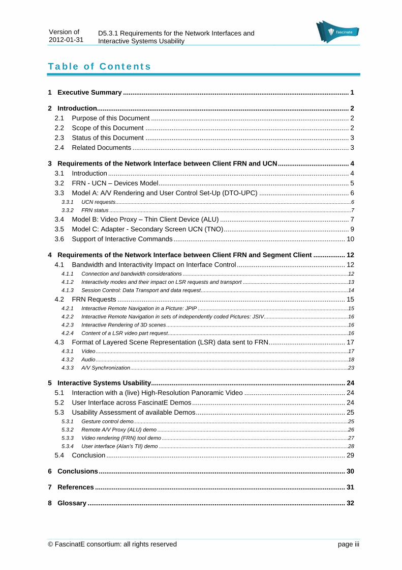
3.6 Support of Interactive Commands A common list of interactive commands has been presented in D1.4.1 and refined in D1.4.2. Using this list as reference, Table 3-1 shows the interactive commands supported by the 3 different instantiations of the FRN-UCN A, B and C models presented in section 3.3, 3.4 and 3.5. In the current implementation, demos B and C use touch based gestures in tablets as input technique while demo A uses visual based gesture recognition.
From the above discussion, it is clear that the Interface between the Client FRN and the UCN might not always be located between a client device and the network but can also be located between the Client FRN responsible of the display and the UCN on a separate device. We focus here on the requirements of this interface with the choice of remaining as independent as possible from the actual configuration chosen.
Sensor Devices
FRN UCN
Actuator Devices
Displays
Primary Screen
Secondary Screen
Touchscreen-based user interfaces
Video Adapter
Secondary Screen User Control
Version of 2012-01-31
D5.3.1 Requirements for the network interfaces and interactive systems usability
© FascinatE consortium: all rights reserved page 11
Interactive command A Fat terminal with Renderer and Gesture-based UCN
B Renderer & UCN in Proxy – Thin Client
C Adapter – Secondary Screen UCN
Selection of Region of Interest / Script
Available Planned Planned
Navigation (scroll X-Y) Available Available Available
Navigation (zoom) Available Available Available
Slow Motion Replays Available Optional Planned
Foreground/Background audio Available Optional
Volume/Mute Available Optional
Sensor type for User Interface
Mouse Available Available
Keyboard Available Available
Gesture-based Available
Touchscreen-based Available Available
Motion-based Available Planned
Table 3-1 List of Interactive commands and Sensor types for the User Interface, which are available for each implementation of the FRN-UCN model.

Version of 2012-01-31
D5.3.1 Requirements for the network interfaces and interactive systems usability
© FascinatE consortium: all rights reserved page 12
4 Requirements of the Network Interface between Client FRN and Segment Client
In this chapter, we describe the requirements and possible protocols of the interface between FRN and Segment Client introduced in chapter 2. Our focus is on a set-up where the FRN and Segment Client functions would be co-located, either in the same device, or (in a demo context) connected through very high-speed physical interfaces. This interface is essentially responsible for transmitting FRN requests towards the delivery and for transmitting LSR A/V data to the FRN.
4.1 Bandwidth and Interactivity Impact on Interface Control We start with high-level considerations on bandwidth, terminal capabilities and interactivity modes and their impact on the control complexity of the Segment Client to FRN interface.
4.1.1 Connection and bandwidth considerations
This connection between Segment Client and FRN should send A/V reconstructed parts of the LSR ideally in raw format so as to avoid another encoding-decoding stage and minimize delay as well as A/V distortion.
In this context, it is useful to discriminate several connection and terminal capability cases based on the available bandwidth capacity between the Segment Client and FRN:
Very High capacity connection (above or equal to 10Gbs): the full LSR is sent in raw format to the FRN, possibly with some spatial filtering decided during the delivery. This only works if the interface exhibits enough bandwidth capacity. This applies to a situation where the FRN and Segment Client are located on the same device. For demonstrator purposes, this can still be approached by connecting the two functional blocks with specific networking hardware (e.g., 10GEthernet technology). This solution is the simplest one in terms of control for the FRN (there is no local texture update management). This interface is then equivalent to a direct production to terminal interface (non interactive as the full LSR is sent).
High capacity connection (between 1 and 10Gbs): reliable but limited bandwidth capacity, this leads to intermediate solutions where the FRN only requests large tiles of the OMNICAM (but could access HD broadcast cams in their entirety); this maps to the interactive-version of direct production-terminal interfaces being discussed. In this case, the requirement is not a strict minimization of the bandwidth, but rather a constraint that it is not possible to transport the full LSR over the interface and/or process it in its entirety at the renderer side. The interface should then exhibit enough interactivity options so that the FRN can easily request the parts of the LSR it needs or follow production script channels1 as well.
Low to Medium capacity connection (below 1Gbs): low or non-reliable bandwidth capacity in this interface (e.g., wireless connection) requires a drastic minimization of the bitrate between the segment client and FRN, e.g. if they are separated by a network. In that case, we may want to only send a Region of Interest or tiles and use at the FRN partial texture update, optionally with texture compression. In this context, the approach enabling most quality of experience is to follow a production script channel with little user interactivity.
Protocols for exchanges of FRN requests and LSR parts over this interface should be able to cover these three different cases. Control complexity is therefore impacted by the available bandwidth in the physical connection of this interface. Another important factor is related to the interactivity modes that FascinatE systems must exhibit for given use cases. We abstract from this analysis the transmission protocol that could be either UDP or TCP-based. This choice will mainly depend on the performances and reliability of the connection technology used.
1In this deliverable, we loosely refer to “production script channel” as a “set of directing rules (either composed by a professional director or a virtual director), which for each frame indicate (1) which LSR parts must be acquired and (2) how to compose and present them in a FRN.”

Version of 2012-01-31
D5.3.1 Requirements for the network interfaces and interactive systems usability
© FascinatE consortium: all rights reserved page 13
4.1.2 Interactivity modes and their impact on LSR requests and transport
Interactivity modes play an important role in the definition of requirements for this interface. We expose here this interactivity in terms of video access but similar considerations can be made for audio. More precisely, we see three main modes of requesting data at a given time:
Frequency of user interaction
Discrete Continuous
Method to reference content
Production Script Channel Mode 1
Direct LSR request Mode 3 Mode 2
Table 4-1 Interactivity modes
Mode 1: Follow a production script channel. The user requests to follow a script as if it was a TV channel. By script here, we refer to a set of directing rules that define for each frame what parts of the LSR should be acquired and how they should be rendered. No interactivity is enabled until the user makes another request. In other words, different LSR requests are made by following a production script channel, but these LSR requests are not made through the interface between the Segment Client and the Renderer but earlier in the delivery where the production script channel is known. It follows that, seen from this interface, as well as from the user perspective, the unique interaction is the selection of the script to be followed.
Mode 2: Fully Interactive navigation into the panorama content. In this mode, the FRN forwards user requests for a new Region-of-Interest with pan-tilt-zoom commands in the Panorama. These commands are interpreted by the UCN and the FRN decides which parts of the LSR must be requested at the frequency with which the user interacts with the UCN. In worst case, this means that a request for different parts of the LSR could be made at every frame.
Mode 3: Semi-interactive navigation into the panorama content. In this mode, the user decides himself which different camera views (here thought as panorama tiles) or production-defined Regions-of-Interests should be displayed rather than following a production script (thus being his own director). However no navigation is foreseen here in the panorama with pan-tilt-zoom commands.
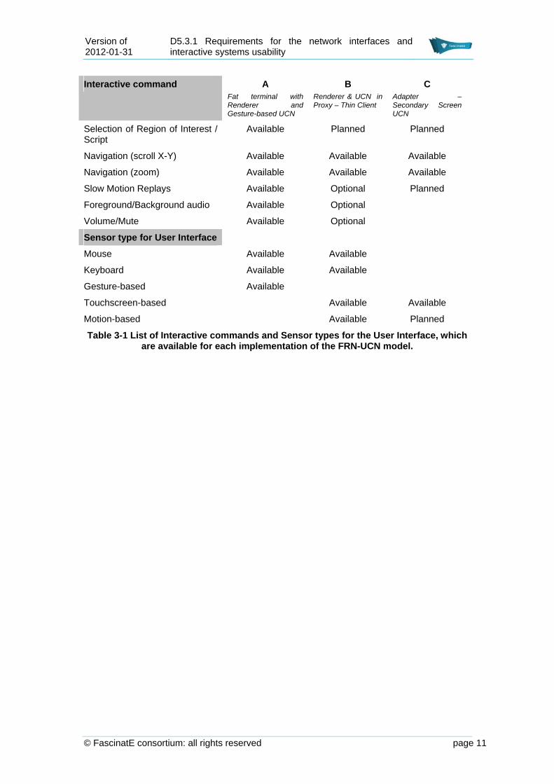
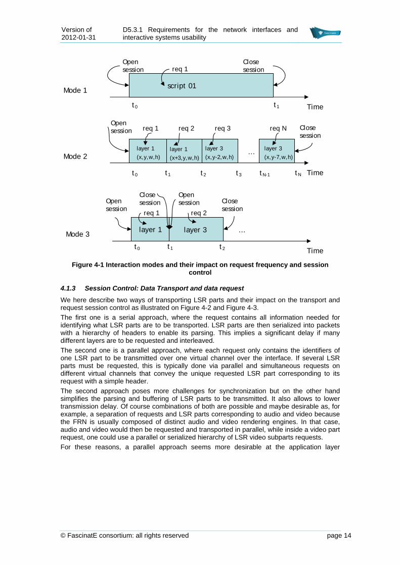
These three different modes, summarized on Table 4-1, imply different challenges in terms of requests as illustrated on Figure 4-1. If they all require opening and closing a mode session, mode 2 is for sure the most challenging in terms of control. Indeed mode 2 requires sending requests at the pace of user interactions. Mode 3 is somehow a trade-off between the non-interactive mode 1 and the fully interactive mode 2. In this mode, it is important to be aware of all possible options that are offered to the user, possibly allowing some mosaic or electronic programming guide displayed by the FRN. It follows that some low resolution versions of other LSR parts must be requested by the FRN together with the user chosen one.
Version of 2012-01-31
D5.3.1 Requirements for the network interfaces and interactive systems usability
© FascinatE consortium: all rights reserved page 14
Figure 4-1 Interaction modes and their impact on request frequency and session
control
4.1.3 Session Control: Data Transport and data request
We here describe two ways of transporting LSR parts and their impact on the transport and request session control as illustrated on Figure 4-2 and Figure 4-3.
The first one is a serial approach, where the request contains all information needed for identifying what LSR parts are to be transported. LSR parts are then serialized into packets with a hierarchy of headers to enable its parsing. This implies a significant delay if many different layers are to be requested and interleaved.
The second one is a parallel approach, where each request only contains the identifiers of one LSR part to be transmitted over one virtual channel over the interface. If several LSR parts must be requested, this is typically done via parallel and simultaneous requests on different virtual channels that convey the unique requested LSR part corresponding to its request with a simple header.
The second approach poses more challenges for synchronization but on the other hand simplifies the parsing and buffering of LSR parts to be transmitted. It also allows to lower transmission delay. Of course combinations of both are possible and maybe desirable as, for example, a separation of requests and LSR parts corresponding to audio and video because the FRN is usually composed of distinct audio and video rendering engines. In that case, audio and video would then be requested and transported in parallel, while inside a video part request, one could use a parallel or serialized hierarchy of LSR video subparts requests.
For these reasons, a parallel approach seems more desirable at the application layer
Time
Open session
Close session
t0 t1
script 01
req 1
Open session
t0 t1 t2
Close session
layer 1
(x,y,w,h)
req 1
layer 1
(x+3,y,w,h)
req 2
layer 3
(x,y-7,w,h)
layer 3
(x,y-2,w,h)
req 3 req N
t3 tN
…
tN-1 Time
Mode 1
Mode 2
Mode 3
Open session
Close session
t0 t1 t2
Open session Close
session
layer 1
req 1
layer 3
req 2
…
Time

Version of 2012-01-31
D5.3.1 Requirements for the network interfaces and interactive systems usability
© FascinatE consortium: all rights reserved page 15
Figure 4-2 Serialized transport of LSR subparts. A global header H describes all necessary information for parsing the packet in a hierarchical way, sub headers sH
describe each subpart identification data and payload size. Blue parts are LSR subparts in raw format
Figure 4-3 Parallel transport of LSR subparts. Similarly to Figure 4-2, headers contain
information for parsing LSR subparts in raw format represented in blue. No global hierarchical header is needed in this case
4.2 FRN Requests FRN requests represent requests from the Client FRN to specific subparts of the LSR. For doing so, the Client FRN needs knowledge from the Production Scripts. However, the FRN Client needs to be agnostic from the encoding formats used in the delivery (delivery uses Delivery scripts for relating the LSR parts of the Production Scripts to their encoded sub-streams). The Segment Client will be responsible for translating FRN requests to stream requests based on Delivery Scripts information.
In the literature, some protocol proposals already exist for different application cases that are dissimilar to the FascinatE use cases. We review here the way they formulate requests and if this format can be directly applied in FascinatE.
4.2.1 Interactive Remote Navigation in a Picture: JPIP
The first one, named JPEG Interactive Protocol (JPIP) [Lima, 2008] is related to interactive requests and remote navigation into high-resolution pictures encoded with JPEG 2000.
With the JPIP protocol, a client does not directly access the compressed file.
Rather, it formulates requests using a simple descriptive syntax which identifies the current “focus window” of the client-side application.
JPIP requests identify the client’s spatial region of interest, resolution and image components of interest, allowing the server to determine the most appropriate response elements and to optimally sequence them.
The JPIP protocol is then able to provide efficient service for interactive imaging, with low round-trip delays, and the opportunity for servers to efficiently manage their resources. It is
sH sH sH H

Version of 2012-01-31
D5.3.1 Requirements for the network interfaces and interactive systems usability
© FascinatE consortium: all rights reserved page 16
however restricted to JPEG 2000 encoded still pictures and cannot directly be applied for FascinatE layered content.
4.2.2 Interactive Remote Navigation in sets of independently coded Pictures: JSIV
An extension of JPIP to intra-coded videos (such as in Motion JPEG) has been very recently proposed by Naman et al. [Naman, 2011]. JSIV utilizes JPEG2000 to independently compress the original video sequence frames and provide for quality and spatial resolution scalability. To exploit inter-frame redundancy, JSIV currently utilizes prediction and conditional replenishment of code-blocks aided by a server policy that optimally selects the number of quality layer for each code-block transmitted and a client policy that makes most of the received (distorted) frames. Future extensions of JSIV may employ motion compensation as well. To optimally solve the server transmission problem, a Lagrangian-style rate-distortion optimization procedure is employed. JSIV provides considerably better interactivity compared to existing schemes and can adapt immediately to interactive changes in client interests, such as forward or backward playback and zooming into individual frames.
Requests are similar to JPIP requests but they also include temporal information.
In [Naman, 2011] experimental results are given for surveillance footage, which does not suffer from the absence of motion compensation. These results show that JSIV’s performance is comparable to that of H.264/SVC in some usage scenarios while JSIV performs better in others. JSIV seems to be a very good candidate for navigation into the panorama content. However, as such, it is still not suitable for the transmission of a complex layered scene. Furthermore, unless it can be proved that motion compensation can be used for JSIV, the compression performance might be insufficient in the case of the highly static panorama content.
4.2.3 Interactive Rendering of 3D scenes
Finally, some similar approaches have been taken for multiple view-base 3D scene transmission under the image rendering paradigm [Zanuttigh, 2005]. The context of this work is an interactive browsing environment, with greedy optimization of a current view, conditioned on the availability of previously transmitted information for other (possibly nearby) views, and subject to a transmission budget constraint.
Here the client requests a field-of-view and a resolution by expressing virtual camera settings (in practice, the client chooses a virtual or real view provided by the server).
The delivery then provides in best effort the desired rendered view in a multiple view rendering context.
The main similarity between these protocols is related to the fact that requests should be made with the knowledge of the “scene” but being agnostic of the way it is actually coded. The delivery is then responsible for providing the requested view/image/frame in a best-effort philosophy. Interestingly, it appears that low round-trip times and good visual quality can be offered using such protocols.
We therefore take a similar approach by specifying the content of LSR parts requests as follows.
4.2.4 Content of a LSR video part request
A FRN request should minimally contain:
A request identifier,
A request timestamp,
either
o a production script channel id (if e.g., we are in the non-interactive mode 1),
o with optionally a desired resolution
or
o LSR layer id
o with optionally the desired resolution

Version of 2012-01-31
D5.3.1 Requirements for the network interfaces and interactive systems usability
© FascinatE consortium: all rights reserved page 17
o and optionally a Field of View (FOV) described as the top left corner, width and height in Panorama coordinates (start_x, start_y, width, height)
Optionally, Status information given as the Id or timestamp of latest received LSR part in the current mode
The request identifier and request timestamp enable to easily identify and re-order received requests at the Segment Client side. Up to now, we do not include yet temporal navigation into the request so as to avoid more difficult synchronization issues. For replays, however, some relative temporal motion might be included in the future as a request if Relays include caching in the delivery in order to allow for this.
Production script channel id and LSR layer id are exclusive in a request as we chose the parallel transport philosophy. For requesting more LSR parts or follow a script channel and LSR parts at the same time, as many requests must be sent in parallel virtual channels on the interface. This is why the request contains an identifier and a timestamp.
The desired resolution and the desired FOV are inspired by the literature (aforementioned JPIP and JSIV), one could further think at sending more optional information that could be useful for the FRN.
Status information might purely be seen as optional and could be replaced by some acknowledgment (for measuring round-trip time etc) sent by the application layer control level. The requests of the client will be served quality-wise in best effort by the Segment Client.
With respect to the interactive mode 2, we do not consider transmitting relative motion of FOV as we estimate that it is the FRN task to translate UCN relative requests in panorama coordinates depending on its rendering mode.
4.3 Format of Layered Scene Representation (LSR) data sent to FRN
The Segment Client transmits A/V data to the Client FRN corresponding to the FRN requests. Parts of LSR that must be sent to the terminal can be separated into Video parts and Audio parts.
4.3.1 Video
Video Data represents by far the major part of the bandwidth between the proxy and renderer, It therefore makes sense to separate it from the audio parts. Video parts of the LSR might be related to the OMNICAM panorama and/or broadcasting cameras such as defined in D1.1.1. Furthermore, the panorama, due to its very large resolution might be tiled (geometric partition) into several independent video substreams. These tiles are not those used by the delivery for video coding and transport as defined in deliverable D4.4.1 but the ones used by the production and described in the LSR. This case corresponds to a direct connection between the FRN and the production as described in D2.1.2.
The main task of the Segment Client is here to stream the raw video frames to the renderer. Optionally, video frames can be texture compressed [Beers, 1998] as these compression formats are directly readable by most GPUs. The main issue is to determine how to encapsulate the video frames corresponding to different parts of the LSR with possibly different resolutions. The requirement is that video frames should be sent in a sequential way that is temporally consistent and contain headers with the needed metadata that enable the renderer to parse and identify these video frames.
Requested LSR video parts will be transmitted together with headers that refer to the information corresponding to the request as described in Section 4.2.4 and possible modifications to it (best effort delivery). It should be noted that the progress on video parts headers and requests is not yet as advanced as audio parts headers and requests. For audio LSR parts, integration efforts are already at the level of listing “specifications” rather than requirements. The format of the video layers and associated metadata on their spatial relationship and how they will be interfaced between production and delivery is still under discussion and finalization at the time of writing.

Version of 2012-01-31
D5.3.1 Requirements for the network interfaces and interactive systems usability
© FascinatE consortium: all rights reserved page 18
4.3.2 Audio
Audio Data is significantly different from the Video Data in terms of data rate and in terms of processing. The proxy here sends the Audio Data as defined in D1.1.1 together with the needed metadata information so that the renderer is able to parse, filter and render the spatial audio objects. Among the metadata, timestamps related to the same clock as the timestamps of the video parts will be required.
Audio Interface Overview
An audio scene consists of several audio tracks. These audio tracks contain single Audio Objects as well as Sound Field descriptions. The number of tracks can vary over time, new tracks can be 'born' and old tracks can 'die'. A good example is the whistle blow of a rugby referee, recorded with a close up microphone. That track will only 'live' (be active in the audio scene) for a few seconds (See Figure 4-4).
Figure 4-4 Relation between audio tracks and frames
Such a scenario, where the number and length of audio tracks is not constant, can be handles using audio frames. The duration of an audio frame is determined by the length of time for which the audio format and number of tracks in the audio scene remains constant. An audio frame consists out of a FrameHeader describing the content of the frame and the audio tracks in the frame.
A FrameHeader can also be used as access point to allow random access at some points in time. Therefore the maximal length of a frame can be defined by the system to e.g. 0.5 seconds, even if the configuration of the audio frame is not changed after this time. It is important to note that audio frames are not synchronized with video frames.
The tracks within an audio frame consist of TrackHeaders and the TrackPayload. Tracks can contain either Audio Object or Sound Field descriptions. Audio Objects consist of mono PCM data with associated position information. Sound Fields consist out of Higher Order Ambisonics (HOA) Coefficients including a HOA format description. The TrackPayload can be split in small segments for streaming purposes. Instead of transmitting the whole frame length track by track, which would require a long buffer, the payload can be split in smaller segments.

Version of 2012-01-31
D5.3.1 Requirements for the network interfaces and interactive systems usability
© FascinatE consortium: all rights reserved page 19
If the bandwidth of the system does not allow to transmit all tracks and all high spatial resolution parts of the HOA signal, the transmitter should limit the number of tracks and the order of the HOA signal. This does not affect the format described here.
The data sequence will be (see Figure 4-5):
1. FrameHeader,containing the number of Tracks T the total number of samples per frame M and the number of samples per segment N.
2. TrackHeaders, 0 to T 2.1. TrackHeader for track 1 2.2. TrackHeader for track 2 2.3. Etc.
3. TrackPayload, in segments (TrackSegments) of N samples for each track, 0 to T. 3.1. TrackSegment, first N samples
3.1.1. TrackPayload for track 1 3.1.2. TrackPayload for track 2 3.1.3. Etc.
3.2. TrackSegment, next N samples 3.2.1. TrackPayload for track 1 3.2.2. TrackPayload for track 2 3.2.3. Etc.
3.3. Etc. 3.4. TrackSegment, last remaining samples until M is reached
3.4.1. TrackPayload for track 1 3.4.2. TrackPayload for track 2 3.4.3. Etc.
Figure 4-5 Sequence of data packages per frame
Audio Interface Requirements
The low level format needs to be defined during the interface specification process. Required are formats for header ID’s and descriptions, which could be string byte arrays and header numbers, which could be integer with little-endian byte order. CamelCase words are proposed but not required field names.
The audio payload should consist out of 2nd complement PCM data with little-endian byte order or floating point data according to IEEE-754. Compression is not foreseen, because that would restrict the frame size and would add extra delay. However it should be foreseen that later enhancements to the specification are possible.
For position information the reference coordinate system has to be defined, as in Figure 4-6.

Version of 2012-01-31
D5.3.1 Requirements for the network interfaces and interactive systems usability
© FascinatE consortium: all rights reserved page 20
Figure 4-6 Reference Coordinate System
The FrameHeader should contain
FrameID, like "F","R","A","M","E"
UniqueFrameNumber
FrameVersionNumber, to be future proof
Unique FrameNumber, which corresponds to the script information
A timestamp, which is the presentation time of the first sample of the frame.
NumberOfTracks, to count the following tracks.
FrameSampleRate, e.g. 48 kHz
Number of samples, for each track. E.g.:
o As long as the audio scene configuration is fixed
o All 0.5 seconds (24000 samples) to allow random access
Number of sample per segment, The smallest audio buffer size which has to be loaded, before the playback can start. E.g.:
o 1 sample, for immediate playback, no latency
o 960 samples to be in sync with Video Frames
o 1152 samples to be align with mp3 compression
o 1024 samples to be to be align with AAC (Advance Audio Codec)
Listener Position (if, for example, more than one Omnicam is used)
Room and Source Information (may be part of script)
TrackHeader
TrackHeader should contain:
TrackID, like "T","R","A","C","K"
UniqueTrackNumber,
TimeStampOffset, in samples
Position, if TrackMovingSourceFlag is false, otherwise the position shall be transmitted in each TrackSegment. Described in angle and distance in radius, inclination
and azimuth ( rs,?s,?s ) relative to the virtual listening position
TrackDescriptor, e.g. “Ball Kick”
TrackType, like AudioObjectTrack or SoundFieldTrack
In case of an AudioObjectTrack the TrackHeader information continuous with:
TrackMovingSourceFlag, indicates if the position is fixed for the whole frame or moving over time. This would require the update of the position in the payload from segment to segment.

Version of 2012-01-31
D5.3.1 Requirements for the network interfaces and interactive systems usability
© FascinatE consortium: all rights reserved page 21
DirectionalPatternType, giving the directional characteristics in either VRML or Spherical Harmonics.
o In VRML two ellipsoids are defined for the maximum level (0 dB) and one larger ellipsoid for a minimum level (-20 dB). The loudness level in between are ramped down linearly. (See Figure 4-7)
o In Spherical Harmonics (SH) the directional characteristics are descripted as a function on a sphere in form of SH Coefficients. (See Figure 4-8)
Direction the source is pointing, if TrackMovingSourceFlag is false, otherwise the direction shall be transmitted in each TrackSegment.
BitDepths, in bits in case of an integer representation. “0” should indicate floating point. This can be different between tracks.
In case of a SoundFieldTrack the TrackHeader information continuous with:
Dimension, 2D or 3D
Ambisonics Order N, remember the number of channels O are is equal to (N+1)^2 in case of 3D.
Orientation of the SoundField
Rotation Parameter
BitDepths, in bit bits in case of an integer representation. “0” should indicate floating point. This can be different between tracks.
Real or Complex Flag
TrackHOAParamCoeffSequence, see Figure 4-9.
o For 2D either:
o upward sequence (
o downward sequence
( .
o For 3D either:
o ‘CG’ sequence (
, or
o ‘QM’ sequence (
;
Normalization, like “Furse-Malham weights”, “Schmidt Semi Normalized” or 4 Normalized

Version of 2012-01-31
D5.3.1 Requirements for the network interfaces and interactive systems usability
© FascinatE consortium: all rights reserved page 22
Figure 4-7 VRML SoundNode directional pattern
Figure 4-8 DirectionalPattern described with Spherical Harmonics
Figure 4-9 HOA Coefficients Sequence
TrackPayload
The TrackPayload are in the same order as the TrackHeaders. The TrackPayload shall be split into smaller segments than the frame length. Each segment contain samples N from all tracks T in the same sequence as the TrackHeaders were transmitted. TrackSegments will be

Version of 2012-01-31
D5.3.1 Requirements for the network interfaces and interactive systems usability
© FascinatE consortium: all rights reserved page 23
repeated until the total frame length M is reached. The last segment will contain the remaining samples.
For AudioObjectTracks the PCM samples shall be transmitted segment by segment followed by the position and direction. The position format is given by the PositionFormat in the TrackHeader. In case of the TrackMovingSourceFlag is set, the position shall follow every segment otherwise the position is transmitted only in the TrackHeader.
For SoundFieldTracks the HOA coefficients shall be transmitted in the indicated TrackHOAParamCoeffSequence field for each SoundFieldTrack segment followed by the rotation.
4.3.3 A/V Synchronization
Synchronization of audio and video parts has to be maintained. This is possible by making use of timestamps in the headers of audio and video parts. However, audio and video parts may be related by user interactions. For example, a video replay is usually not performed together with the audio replay. For this reason, the actual synchronization is performed by the renderer itself while the proxy makes sure timestamps are transmitted to the proxy.
The transmitter shall transmit A/V timestamps as well as clock references to synchronize the receiver clock. Audio timestamps shall be transmitted each audio frame, and the timestamp should indicate the playback time of the first sample of an audio frame.

Version of 2012-01-31
D5.3.1 Requirements for the network interfaces and interactive systems usability
© FascinatE consortium: all rights reserved page 24
5 Interactive Systems Usability
This section is organized as follows. Interaction with the FascinatE as a high-resolution panoramic video from the end-user perspective is introduced in Section 5.1. Section 5.2 explains approach taken to ensure “common look and feel” across FascinatE demos, while Section 5.3 presents results of the “quick and dirty” evaluation of the available FascinatE demos.
5.1 Interaction with a (live) High-Resolution Panoramic Video A high-resolution panoramic video of an event offers the viewers various views of the event and the possibility to choose what they want to see. This is in contrast to traditional TV viewing, where only pre-selected views are offered to the viewer. Thus, compared to the established technology, having a panoramic view can be seen as “having everything”. In this sense a TV production becomes massive, with more content being offered than can be possibly consumed by the viewers.
The question is what it actually means for TV viewers to get the possibility to select (m)any view(s) and level of detail of an event. In the last decade, there has been a lot of research on interactive TV (iTV) resulting in novel systems offering advanced viewing features. Consequently, a range of interactive functions has been suggested for viewers enabling much more than traditional channel and volume changing, while at the same time not so much effort is invested in studying viewers’ needs. Moreover, live video material brings new challenges and a need for novel types of interaction - the viewing of live events requires real-time interaction, and mistakes in handling the content could lead to a possible loss of important information.
Our aim is to better understand potential viewers’ use of such mass data and interaction with high-resolution panoramic video, i.e., we are concerned with how having access to ”every possible view” would influence the TV viewers’ experience of TV watching compared to having only a certain view of the event. This is necessary in order to be able to design (a) good user interface(s) and interaction with such mass content.
5.2 User Interface across FascinatE Demos End-user preferences within the FascinatE project are defined based on the user studies, either in the form of ethnographic studies (for example sport bar studies described in D5.1.1) or as prototype testing based on demos defined and developed in WP5 (video and audio renderers and interface mock-ups). So far collected end-user preferences, as well as functionality requirements for the FascinatE system are given in forthcoming D1.1.2. With both user and functionality requirements set, preconditions for the design of user interface are met. It is important to note here that the design of the end-user interface follows an iterative design process, where results of each test or study are used to inform the next one, while at the same time the current end-user preferences are further refined. Since the FascinatE system will be used on different platforms and in various scenarios, it is desirable to define a high level perspective on the user interface, and in that way ensure a transparent demonstration of FascinatE functionalities through the demos.
Components needed are:
1) Major functional elements (data)
2) Flow between elements (interaction)
3) Input (interaction) technique
Components 1) and 2) are needed for building Information architecture, i.e. development of the process and information flow of the system. User interface flow models interaction that user have with the software. Also, it gives architectural view of the UI (high level overview). Thus, components 1) and 2) need to be common across different FascinatE demos. On the other hand, component 3), input techniques considered within FascinatE, is demo specific, and will be separately described, together with the matching demo.

Version of 2012-01-31
D5.3.1 Requirements for the network interfaces and interactive systems usability
© FascinatE consortium: all rights reserved page 25
A definition of afore mentioned components gives the base for the User Interface design with the “common look and feel” through the various planned demos. For the FascinatE it is a graphical user interface (GUI). High-level overview of the user interface will be defined based on the prototype testing.
5.3 Usability Assessment of available Demos In this stage of the FascinatE project several demo applications were available whereas each of them was focusing on the specific FascinatE connected feature/issue. Since those demos were basically very rough prototypes, laboratory based testing was performed in order to get a general understanding of the user interaction with the FascinatE tools. Also, demos were available for the evaluation in the various stages of maturity, as well as in different environments and time periods, so the applied evaluation method slightly differs in between them. In the next iterations, in addition, heuristic evaluation and naturalistic evaluation are also planned.
5.3.1 Gesture control demo
Evaluation of the gesture control demo is based on the observations at IBC. It is important to be aware that the users were affected by the context - the interaction was mainly a testing of the gesture recognition technique and not an immersed interaction with the (broadcast) content. This evaluation should be seen as initial (small!) study of the first gesture demo.
Description (usage and interaction)
The first gesture demo was about panorama navigation (panning and zooming) using gesture recognition. More information can be found in [Newsletter, 2011].
In order to interpret user gestures as means to navigate within a panorama, hands and heads are tracked by exploiting depth estimation. For tracking the hands to understand the performed gestures, a workspace is defined as a 3D box, placed in relation to the detected head position. Within this 3D box, hands are detected by merging and filtering samples with similar size and depth information. Interaction goes, so that one.
One hand goes in the 3D box in front of you, one hand enters the 3D box then you point it (close it) and the dragging with the hand navigates through the panorama. The same motion is performed but with two hands (two hands enter the 3D box, then point or close) and separating or closing together your hands controlled the amount of zoom in the panoramic view. Feedback about the gestures is shown on the screen. Your hands were painted in the same screen as the panorama and changing in shape when you did the pointing/close of them. So it could be distinguished between one and two hands interaction in the 3D box (as 1 or 2 hand icons appeared), and if the hands where open or pointing/closed. Figure 5-1 shows an example of the gesture used for interacting with the gesture control demo.
Figure 5-1: Interacting with gesture control demo
Evaluation results
Method: For the evaluation purposes, users of the gesture demo at the IBC were video recorded, and the videos were analysed.
Remarks from the first small study on the use of gesture recognition:

Version of 2012-01-31
D5.3.1 Requirements for the network interfaces and interactive systems usability
© FascinatE consortium: all rights reserved page 26
The symbols on the screen (red and green hands) need to be connected to the actual movement that you are supposed to perform. If the symbol is a fist the gesture should not be pointing etc. These images are crucial especially since it seems like all the users are interacting depending on these symbols. An example behaviour from one of the recorded users: “He does a lot of waving that doesn't seem to get any response in the system (is it too "soft"?). He is mimicking the symbols but doesn't do very much else (but maybe he doesn't know how to). He moves closer to the screen to get more response. He also tries to move with his body as well.”
A library (list/bar) of gestures could be shown at the bottom of the screen. I.e. something that could appear if you need it (not there all the time).
Problematic is that the gestures only can be made with a certain distance from the body since gesture recognition is made (mostly) for the home scenario where the gestures should be made in a context of a relaxed sofa (leaning-back) etc. Many of the users were also just using one hand.
When using the zooming gestures people seemed to have troubles with zooming all the way. They ended up zooming in and out instead. Therefore it doesn't seem clear on how the interaction should be made. It seems like people are more interested in panning the image than zooming. Although, this might be because this is "easier". This is an example description of the demo use of one of the recorded participants: “It seems like he drags the picture hard to get "into it" (kind of immersive). Flat hand doesn't look very "natural" or comfortable in front of the screen. He has problems with the zooming.
5.3.2 Remote A/V Proxy (ALU) demo
The demo that was evaluated was the first iteration of the remote A/V Proxy demo.
Description (usage and interaction)
More information can be found in [Newsletter, 2011]. In this demo high resolution panoramic content was decoded once for all clients (for the purpose of evaluation, only one client was used), panning and zooming was done on the server side, while reframing and coding was in real-time. The client used was Nokia mobile phone N900 as shown on Figure 5-2.
Figure 5-2: N900 client
Users were able to zoom (using the hidden menu on the left side) and to pan using the stylus or touch screen.
Evaluation results
Method: Evaluation of this demo was done as laboratory participatory study. Five participants were given the phone with the demo, instructed how to use it and observed.
These are remarks from the initial study of this demo:
Easy access to full panorama is missing (one click or move). Users appreciate having the panorama picture and exploring it. The consequence is that they often get lost, thus it is needed to have an easy access to the panorama overview.

Version of 2012-01-31
D5.3.1 Requirements for the network interfaces and interactive systems usability
© FascinatE consortium: all rights reserved page 27
Most of the participants complained on the stylus (touch screens on this types of phones do not respond well). They are so much used to touch screens and the use of it with fingers that they are not happy with having something in the hand. Also the problem of losing it was frequently mentioned. Another complain about the stylus was that it was too hard – a soft edge stylus would be appreciated, especially in the combination with a tablet instead of mobile phone.
All the users had problem with finding the hidden menu on the left. It takes some time to get used to it. Also, being placed on the left, interaction with it for right-handed people means covering the whole screen and not seeing what is happening.
Both panning and zooming are problematic, if the user interacts with it “too fast”. In that case, zooming/panning do not follow the movement, and generally users tend to repeat the movement. That leads to getting not wanted content and often user frustration. It is necessary that the precise movement on the screen immediately follows the user interaction – viewers are extremely sensitive on the late response! They need immediate feedback as confirmation for the interaction done. On the other hand, having only “slow movements” is not an option for most the cases, since there is so much happening on the screen, in the panorama picture, especially taking a football as an example.
Also, zooming realized with the pinch gesture (as it is on the most smart phones) is what users want (instead of menu) since they are so much used to it. It is what they consider the natural movement.
All the users also commented on the “flying window”. In the cases when the height of the screen was not filled with the picture (overview panorama or almost an overview), when panning, the picture would move up and down, annoying users. It should be fixed so that only left and right movements are possible.
End users appreciated having an overview panorama on the screen and the possibility to interact with it in real-time. As well, the functionality from the FascinatE perspective was clearly shown. However, basic usability issues as mentioned above should be fixed in the next iteration of this demo.
5.3.3 Video rendering (FRN) tool demo
Here we describe results of micro interaction study of the FRN tool demo. The study was small, and further user studies are planned with this demo.
Description (usage and interaction)
The FRN tool demo aims to visualize key features of FascinatE (as they are in an early stage of the project). Initial concepts used for rendering are described in D5.1.1, while more details about the tool is written in D5.1.2 chapter 3.4. A panorama is rendered with the perspective corrected based on a selected view. In the demo version of the video renderer that was evaluated, the users could directly change the view (pan/tilt/zoom) via mouse/trackball/keyboard. Figure 5-3 shows a screenshot from the video renderer prototype.

Version of 2012-01-31
D5.3.1 Requirements for the network interfaces and interactive systems usability
© FascinatE consortium: all rights reserved page 28
Figure 5-3: Detail from the video renderer prototype
ROIs (suggestions where the user may see interesting things) are announced as icons in the bottom left corner and can be shown as graphical overlay to the main video. It is possible to follow automatically one of these scripts or to do a smooth transition between them.
Evaluation results
Method: Evaluation of this demo was done as laboratory participatory study. Four participants were asked to try the demo, instructed how to use it and observed.
These are remarks from the initial study of this demo:
The need to zoom out completely, in order not to miss important action, or professionally produced stream to choose from (e.g. the ball is too fast and it is hard to follow it in the panorama). But also a close-up view and the view from different angles to see what they really do – „why did he get tackled“
Although in general participants commented that they would get tired by interacting too much, some of them loved to play with the available content, and would love to have more possibilities, like sharing with others the specific moments, and choosing angles etc.
Participants appreciated panorama - it is something that you usually do not get, and it gives a good overview. Thus easy access to it is needed.
Interesting content (i.e. ROI) accessible on click, for easy choosing of available options.
Touch screen as a second screen and device for interacting – participants felt that touch screen gesture interaction would be more natural way to interact with the content.
5.3.4 User interface (Alan’s TII) demo
This demo represents a first iteration of the end user interface design. Evaluation results obtained from this demo testing, as well as from other available demos as described previously, will be used to inform the design of the next iteration of the user interface.
Description (usage and interaction)
The aim of the User Interface demo is to evaluate a design proposal for the FascinatE use on the mobile terminals [Larsson, 2011]. The design proposal for the mobile study is based on the user studies and design workshops, partly described in D1.1.2 and D5.1.1. This demo is created as a mock-up (not using real panoramic video), allowing users to navigate a panorama picture on the mobile phone.

Version of 2012-01-31
D5.3.1 Requirements for the network interfaces and interactive systems usability
© FascinatE consortium: all rights reserved page 29
Figure 5-4: User interface showing panorama and ROIs
This demo can be used on any Android based smart phone.
Evaluation results
Method: Evaluation of this demo was done as laboratory participatory study. Six participants were asked to try the demo, instructed how to use it and observed.
General impressions of the application were that it was a cool application with a clean design and that they would most likely use the application as a means to kill time. Everyone understood what the different tabs represented without the need for further help. Participants generally liked the FascinatE View and thought the controls were well-balanced, simple and easy to use when known. However, all participants tried to select a ROI with a single tap, and after several tries they abandoned single tap and tried the pinch interaction instead. After learning that one could double tap on the ROI frames they all quickly adopted it and most thought it was better than a regular tap. One participant liked the idea of ROI frames and said that he would probably choose one and then do adjustments with the regular controls if needed. When asked to compare the FascinatE View with regular broadcasts some participants linked it with the Internet, where users choose what to consume rather than just receive. Most of the participants wanted to have the option to switch between different cameras/camera angles in the FascinatE View in order to get a better view of a tackle.
5.4 Conclusion “Quick and dirty” evaluation of the four available demos clearly showed that the potential viewers appreciate having a panoramic picture and the possibility to navigate within it. However, there is an obvious need for quick return to the starting point (e.g. panorama overview) since exploration of the content can easily lead to the loss of important information or/and to the stress caused by too much given control. As well, from the same reasons, an easy access to the professionally produced broadcast of the event is needed. Another conclusion that came out from these studies is that viewers’ current viewing and interaction practices shouldn’t be neglected.
Results presented here will feed into next iteration of demos, i.e. they will inform the design of the FascinatE end-user interface as mentioned in Section 5.2.

Version of 2012-01-31
D5.3.1 Requirements for the network interfaces and interactive systems usability
© FascinatE consortium: all rights reserved page 30
6 Conclusions
This deliverable had three objectives.
In chapter 3, we clarified the different integration paths between the UCN and FRN planned in the project. The first objective related to this part has been met. For this interface, a special care has been taken on the interface definition on existing demonstrators architectures. We observed that the different set-ups have distinct requirements, depending on the locations of some functional blocks. Further developments of demonstrators will now have a common architecture view on the complex interface between the FRN and UCN depending on the use case and the sensor or interaction mode. This study enables to better define how future extensions of current demonstrators can be integrated at the terminal side. In particular, further integration between set-up A and C will be investigated.
In chapter 4, we aimed at studying the requirements of the network interfaces at the terminal side of the end-to-end FascinatE architecture, that is between the Segment Client and the Fascinate Rendering Node interface. These requirements can vary depending on the context of the different use cases proposed in FascinatE. The aspects that have been taken into account for the first interface are (but are not limited to) network bandwidth capacity, data (Layered Scene Representation parts) requests and serialization for transport, session control and interaction modes.
The second objective related to this chapter has also been achieved since a comprehensive list of requirements as been set on the FRN-Segment Client interface for video parts of the LSR, and even a list of specifications for the audio parts of the LSR. The roadmap to develop such protocols over these interfaces will be given in deliverable D1.4.2.
The last chapter of the deliverable, related to the third objective (usability studies of interactive systems), provides the usability evaluation of four demonstrators in the context of FascinatE. These evaluations have highlighted what interactivity features are of special importance for user quality of experience. It is shown in this deliverable that potential viewers appreciate having a panoramic picture and the possibility to navigate within it. However, there is an obvious need for quick return to the starting point (e.g. panorama overview) since exploration of the content can easily lead to the loss of important information or/and to the stress caused by too much given control. As well, from the same reasons, an easy access to the professionally produced broadcast of the event is needed. Another conclusion that came out from these studies is that viewers’ current viewing and interaction practices must be taken into account.
The last objective of this deliverable is also clearly achieved. With respect to future work, based on the evaluation results of each demonstrator, as well as on the general conclusions, a new version of demonstrators will be developed, and evaluated. Besides, regarding the interactivity functionality, the plan is that this new iteration concentrates more on the user interface in order to define a FascinatE "common look and feel".

Version of 2012-01-31
D5.3.1 Requirements for the network interfaces and interactive systems usability
© FascinatE consortium: all rights reserved page 31
7 References
[Beers, 1996] A. Beers; M. Agrawala, N. Chaddha (1996), "Rendering from Compressed Textures", Computer Graphics, Proc. SIGGRAPH: 373–378
[Larsson, 2011] A. Larsson (2011), "Design proposal for the mobile FascinatE project", Master Thesis at Umeå University, Department of Computing Science, October 2011.
[Lima, 2008] L. Lima, D. Taubman, R. Leonardi, "JPIP proxy server for remote browsing of JPEG2000 images," Multimedia Signal Processing, 2008 IEEE 10th Workshop on , vol., no., pp.844-849, 8-10 Oct. 2008
[Macq, 2011] J.F. Macq, N. Verzijp, M. Aerts, F. Vandeputte, E. Six, “Demo: Omnidirectional video navigation on a tablet PC using a camera-based orientation tracker”, in Proceeding of the Fifth International Conference on Distributed Smart Cameras (ICDSC 2011), Ghent, Belgium, August 2011.
[Naman, 2011] A.T. Naman, D. Taubman, "JPEG2000-Based Scalable Interactive Video (JSIV),", IEEE Transactions on Image Processing, vol.20, no.5, pp.1435-1449, May 2011
[Newsletter, 2011] FascinatE Newsletter, September 2011, http://www.fascinate-project.eu/wp-content/uploads/2011/05/IBC_Newsletter.pdf
[Nielsen, 1994] J. Nielsen, Ten usability heuristics by Jakob Nielsen, http://www.useit.com/papers/heuristic/heuristic_list.html, Accessed: November 18, 2011
[Zanuttigh, 2005] P. Zanuttigh, N. Brusco, D. Taubman, G. M. Cortelazzo, “Greedy non-linear approximation of the plenoptic function for interactive transmission of 3D scenes”, Proceedings of the International Conference on Image Processing, (1), pp. 629-632, 2005

Version of 2012-01-31
D5.3.1 Requirements for the network interfaces and interactive systems usability
© FascinatE consortium: all rights reserved page 32
8 Glossary
Terms used within the FascinatE project, sorted alphabetically.
AAC Advance Audio Codec
FOV Field-Of-View
FRN FascinatE Rendering Node
HOA Higher Order Ambisonics
JPEG ISO/IEC Joint Technical Committee of Photographic Experts
JPEG2000 Picture compression format
JPIP JPEG2000 Interactive Protocol
JSIV JPEG2000-based Scalable Interactive Video
ROI Region-Of-Interest
SH Spherical Harmonics
UCN User Control Node
H.264 Video compression format
SVC Scalable Video Coding
Partner Acronyms
ALU Alcatel-Lucent Bell NV, BE
ARI Arnold & Richter Cine Technik GMBH & Co Betriebs KG, DE
BBC British Broadcasting Corporation
DTO Technicolor, DE
HHI Heinrich Hertz Institut, Fraunhofer Gesellschaft zur Förderung der Angewandten Forschung e.V., DE
JRS JOANNEUM RESEARCH Forschungsgesellschaft mbH, AT
SES Softeco Sismat S.P.A., IT
TII The Interactive Institute, SE
TNO Nederlandse Organisatie voor Toegapast Natuurwetenschappelijk Onderzoek – TNO, NL
UOS The University of Salford, UK
UPC Universitat Politecnica de Catalunya, ES