requirements - faculty of engineering and applied science...
TRANSCRIPT

1
Requirements
Domain model. Lexicon. User stories. Use cases.

Elements of a Requirements Spec.
! Domain model and lexicon ! Functional Requirements (user stories) ! Nonfunctional requirements ! Use Case.
© 2003--2009 T. S. Norvell Engineering Memorial University Slide set 3. Slide 2

Domain Model and Lexicon
! The domain model is a class diagram ! Classes describe objects of the domain. ! These might be physical objects or objects
that exist only in the computer, but they should be objects that users (in general stakeholders) would be aware of. " E.g. For accounting software, accounts, journal
entries, summary reports, etc.
© 2003--2009 T. S. Norvell Engineering Memorial University Slide set 3. Slide 3

Functional requirements
! Functional requirements express goals the stakeholders (e.g. users) desire to be able to accomplish using the system.
! Functional requirements are often expressed with user stories.
! User stories sentences of the form As a ____ I need to ___ in order that ____.
! + some clarifying material.
© 2003--2009 T. S. Norvell Engineering Memorial University Slide set 3. Slide 4

Nonfunctional requirements
! Functional requirements focus on the relationship between inputs and output.
! All other requirements are nonfunctional. " Platform constraints.
! Must run on Windows 10, and Max OX 10.8 " Performance constraints
! Must process up to 100 transactions per second. " Reliability constraints
! Must continue to operate when up to 5 of the 6 CPUs have failed.
© 2003--2009 T. S. Norvell Engineering Memorial University Slide set 3. Slide 5

© 2003--2009 T. S. Norvell Engineering Memorial University Slide set 3. Slide 6
Use Cases
! “Use cases” are used in requirements, specification, and design documents to specify the behaviour of a system from an external point of view.
! Each use case specifies how the system may interact with one or more external “actors”.
! Typical “actors” : users, operating systems, other systems, hardware devices.

© 2003--2009 T. S. Norvell Engineering Memorial University Slide set 3. Slide 7
Use Cases
! Each use case describes a set related scenarios”.
! A “scenario” is a sequence of interactions between system and external actors.
! A complete set of use-cases specifies all scenarios the system must be capable of participating in.

© 2003--2009 T. S. Norvell Engineering Memorial University Slide set 3. Slide 8
“What” not “how”
! A use case (partially) defines the external behaviour of a system,
! without revealing the internal structure of the system.
! It is a black-box specification. ! Only mention events that cross the system
boundary and artefacts that are in the domain model

Case study: The Autotest 2.0 system.
Autotest 2.0 is an off-line system for testing student assignment submission.
© 2003--2009 T. S. Norvell Engineering Memorial University Slide set 3. Slide 9

Case Study: Domain model
© 2003--2009 T. S. Norvell Engineering Memorial University Slide set 3. Slide 10

Case study: Lexicon
! Assignment. An assignment is a description containing all the information needed to test a set of submissions. This includes a set of parts, instructions for writing reports, names of the submit, marked, and working directories.
! Submission. The submission of one student. This is a set of files in a subdirectory of the submit directory.
© 2003--2009 T. S. Norvell Engineering Memorial University Slide set 3. Slide 11

Case study: Lexicon
Lexicon: (excerpt continued) ! Run. To run an assignment is to execute all
tests for one or more student submissions. Running an assignment produces one report file per submission and copies the submitted files to produce marked files.
© 2003--2009 T. S. Norvell Engineering Memorial University Slide set 3. Slide 12

© 2003--2009 T. S. Norvell Engineering Memorial University Slide set 3. Slide 13
Case study User Stories
! Here are some of the requirements for the system: " R0: As an instructor I need to create new assignments. " R1: As an instructor I need to be able to edit previously
saved assignment. " R13: As an instructor I need to be able to exit at any time
with a choice of saving unsaved changes. " R42: As an instructor I need to save edited assignments.

© 2003--2009 T. S. Norvell Engineering Memorial University Slide set 3. Slide 14
Use cases for AT2.0
! We will look at 3 use-cases from this system " Start-up " Exit " “Save assignment”
! These are quite low level use-cases and might belong in the design rather than in the specification.
© 2003--2009 T. S. Norvell Engineering Memorial University Slide set 3. Slide 15
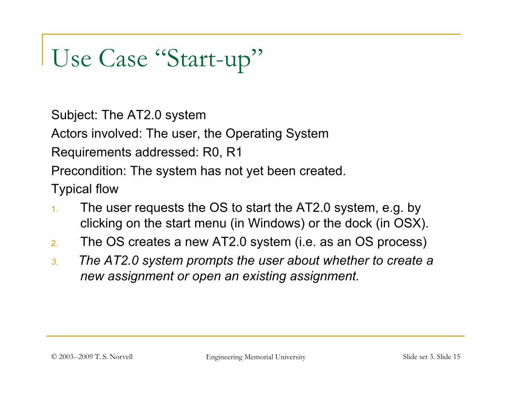
Use Case “Start-up”
Subject: The AT2.0 system Actors involved: The user, the Operating System Requirements addressed: R0, R1 Precondition: The system has not yet been created. Typical flow 1. The user requests the OS to start the AT2.0 system, e.g. by
clicking on the start menu (in Windows) or the dock (in OSX). 2. The OS creates a new AT2.0 system (i.e. as an OS process) 3. The AT2.0 system prompts the user about whether to create a
new assignment or open an existing assignment.

© 2003--2009 T. S. Norvell Engineering Memorial University Slide set 3. Slide 16
Use Case “Start-up” (cont)
4 If the user picks “new assignment” a. The system prompts the user as to whether to base the new
assignment on an existing file. b. If the user selects “no”, the system creates a new assignment with
default values c. Else if the user chooses "yes", the system prompts for a file and a new
assignment is created based on the contents of that file, but the file name is not associated with the assignment.
5. Else if the user chooses to open an existing assignment, they are prompted for a file and an assignment is created based on the file. The name of the file is associated with the assignment.

© 2003--2009 T. S. Norvell Engineering Memorial University Slide set 3. Slide 17
Use Case “Start-up” (cont)
6 The system displays its main window (See Figure X) to the user. The main window contains a menu bar, a tool bar, an assignment editor, and a log echo area. The assignment editor contains graphical controls to alter all attributes of the assignment and its parts. (See section Y)
Postcondition: “The system is started”
Alternative flows ! If the user selects cancel in the file picker (in steps 4.c or 5),
the process starts again at step 3.

© 2003--2009 T. S. Norvell Engineering Memorial University Slide set 3. Slide 18
Use case “Exit”
Subject: The AT2.0 system Actors involved: The user, the operating system Requirements addressed: R13 Precondition: “The system is started” 1. The user selects the exit from the menu, from the toolbar, or by
using the OS to send a “close” message to the main window. 2. include “ensure the data is safe” 3. The system requests the OS to terminate its process. Postcondition: “The system is terminated” Alternative paths: If the user selects cancel in step 2 the use case stops
with postcondition “The system is started”.

© 2003--2009 T. S. Norvell Engineering Memorial University Slide set 3. Slide 19
Use Case: “Ensure the data is safe”
Inclusion Use Case. Subject: The AT2.0 system Actors involved: The user, the operating system 1. If there are unsaved modifications to the data, then
a) The system prompts the user as to whether to save the data with choices: Yes, no, or cancel
b) The user makes a choice c) If the user chooses ‘yes’, then
1. Include “the assignment is saved” Postcondition: done Alternative paths: If the user selects cancel in step 1.b,
the use case stops with postcondition “the user selected cancel”.

© 2003--2009 T. S. Norvell Engineering Memorial University Slide set 3. Slide 20
Use case “Save assignment”
Subject: The AT2.0 system Actors involved: The user, the OS Requirements addressed: R42 Precondition: The system is started. Typical Flow 1. The user initiates the Save action from the Menu or
tool bar. 2. Include: “The assignment is saved.” Postcondition: The system is started

© 2003--2009 T. S. Norvell Engineering Memorial University Slide set 3. Slide 21
Use Case: “the assignment is saved”
Inclusion Use Case. Subject: The AT2.0 system Actors: The User and the OS Typical flow 1. If no file is associated with this assignment, then
a. the system responds with a file chooser dialog. b. the user supplies a name for the file c. the name supplied becomes the name associated
with the assignment.

© 2003--2009 T. S. Norvell Engineering Memorial University Slide set 3. Slide 22
Use case “The assignment is saved” (cont.)
2. The Assignment is written to file via the OS. Alternate paths: ! If the user selects "Cancel" in the file
chooser, the file is not saved and the operation is aborted.
! If any error happens when writing the file, then the save is aborted and the user is informed of the error.

© 2003--2009 T. S. Norvell Engineering Memorial University Slide set 3. Slide 23
Use Case Diagrams
! Show which actors are involved in which use cases. ! Show dependencies between use cases.

© 2003--2009 T. S. Norvell Engineering Memorial University Slide set 3. Slide 24
Pre- and postconditions as states
! Pre- and postconditions of use cases provide a very high-level state model for the system.
© 2003--2009 T. S. Norvell Engineering Memorial University Slide set 3. Slide 25
“Essential” vs. “Concrete” Use Cases
! The above examples, are “concrete” use cases. Low level and detailed. Useful to designers and coders.
! “Essential” use cases ignore detail (including UI and some alternative paths) to concentrate on the essence of the use case.
! We might use essential use cases in the requirements doc and concrete use cases in the specification or design doc.

© 2003--2009 T. S. Norvell Engineering Memorial University Slide set 3. Slide 26
Use case “Save assignment” (Essential)
Subject: The AT2.0 system Actors: The user, the OS Requirements: R42 Precondition: The system is started. 1. The user requests to save 2. The system saves the file, obtaining a file
name from the user, if need be. Postcondition: “The system is started”

© 2003--2009 T. S. Norvell Engineering Memorial University Slide set 3. Slide 27
Notes on Use Cases.
! If well written, can be reviewed by non-software engineers: Users, Product managers, Customers.
! Each item in the flow should indicate the actions of one actor (or the system).
! Usually are not right or complete or consistent the first-time. Should be reviewed and refined repeatedly by all stake-holders.
! Can be used to drive iterative process. E.g. “In this iteration we will implement the following use cases ‘Start-up’, ‘Save’, and ‘Exit’.”
! Serve as a link between requirements and design. ! Serve as a basis for system testing.

Further Reading
! Craig Larman: Applying UML and Patterns ! Doug Rosenberg and Matt Stephens: Use
Case Driven Object Modeling with UML
© 2003--2009 T. S. Norvell Engineering Memorial University Slide set 3. Slide 28