request for proposals (rfp) 2020-002182 construction and
TRANSCRIPT

Request for Proposals (RFP) 2020-002182 Construction and Engineering Services for Underground
Construction: PacWave South
ISSUE DATE: 12/27/2019
QUESTION DEADLINE: 02//06/2020 at 5:00 PM Pacific Time All questions should be sent to [email protected]
Please include RFP Title in the subject line.
PROPOSAL DUE DATE/TIME: 03/11/2020 at 2:00 PM Pacific Time
*Office is closed Noon to 1:00 PM Daily
MANDATORY PRE-PROPOSAL CONFERENCE: 01/30/2020 from 9:00 AM to Noon Pacific Time
beginning at the entrance to the Visitor’s Center at the Hatfield Marine Science Center (2030 SE Marine
Science Drive, Newport, OR 97365).
CONTRACT ADMINISTRATORS:
Hanna Emerson & Ben Baggett Construction Contract Administration
Oregon State University 644 SW 13th Street
Corvallis, OR 97333 Phone: (541) 737-3401
Email: [email protected]
AWARD DECISION APPEALS:
Kelly Kozisek, Director & Chief Procurement Officer
Procurement, Contracts and Materials Management Oregon State University
644 SW 13th Street Corvallis, OR 97333
Phone: (541) 737-2067 Email: [email protected]
It is the Proposers responsibility to continue to monitor the OSU Business and Bid Opportunities website for
Addenda. Failure to acknowledge any Addenda in the Transmittal Letter may cause your proposal to be considered non-responsive.
OSU standards and policies govern this solicitation (Procurement Thresholds and Methods, Procurement Solicitations
and Contracts) unless otherwise referenced or stated.
RFP Response due 3/11/2020 at 2:00 pm, Pacific Time Page 2 of 27
1. GENERAL
1.1 In-Kind Contributions for Cost Share Support Proposers may assist OSU to meet the cost share obligation required as a condition of the receipt and use of the federal funding from the U.S. Department of Energy (“DOE”) provided to support PacWave. Allowable costs that OSU can report in meeting this cost share obligation may include discounted goods or services, in-kind contributions, or direct gifts to the Project. Proposers seeking to assist OSU to make this cost share obligation through an in-kind contribution, gift, or discount of goods or services are asked to contact Heidi Sann, Associate Vice President of Finance and Controller at [email protected]. Any discount, gift, or in-kind contributions made by Proposers are strictly voluntary and must be in accordance with OSU, OSU Foundation and federal rules. In-kind contributions, gifts or discounts to assist OSU to meet cost share obligations are not evaluated and will not influence contract award.
Entities other than proposers may also assist OSU to meet the cost share obligation.
1.2 Schedule of Events The selection procedure described below will be used to evaluate the capabilities of interested companies to provide the services to Oregon State University (“OSU” or “Owner”) for this project. All times below are given in Pacific Time. The selection procedure described below will be used to evaluate the capabilities of interested companies to provide the services to OSU for this project.
Schedule with Interviews:
12/27/2019 Issue RFP
01/30/2020 Mandatory Pre-Proposal Conference at 9 a.m.
02/06/2020 Question Deadline at 5:00 p.m.
02/14/2020 Final Addendum Issued (tentative)
03/11/2020 Proposals due 2:00 p.m.
03/25/2020 Notification of finalists
04/01/2020 Estimated Interviews with Selection Committee
04/08/2020 Estimated Notice of Intent to Award
05/01/2020 Estimated Contract Execution
Schedule without Interviews:
12/27/2019 Issue RFP
01/30/2020 Mandatory Pre-Proposal Conference at 9 a.m.

RFP Response due 3/11/2020 at 2:00 pm, Pacific Time Page 3 of 27
02/06/2020 Question Deadline at 5:00 p.m.
02/14/2020 Final Addendum Issued (tentative)
03/11/2020 RFP Response due 2:00 p.m.
03/25/2020 Notice of Intent to Award
04/22/2020 Estimated Contract Execution
1.3 Pre-Proposal Conference and Site Visit A Mandatory Pre-Proposal Conference and Site Visit will be held from 9:00 a.m. to noon Pacific Time on January 30, 2020 starting and concluding at the entrance to the Visitor’s Center at the Hatfield Marine Science Center (2030 SE Marine Science Drive, Newport, OR 97365). The site visit will include visiting Driftwood Beach State Recreation Site (“the shore landing site” or “Driftwood”) and the Utility Connection and Monitoring Facility (“UCMF”) site on NW Wenger Lane, Seal Rock, OR. NOTE: Proposers must attend this Pre-Proposal Conference in its entirety in person to be eligible to submit a proposal. Failure to attend shall result in that Proposer being non-responsive and rejected from further evaluation.
1.4 Issuing Office The Construction Contracts Administration (“CCA”) unit of OSU’s Procurement Contracts and Materials Management (“PCMM”) department is the issuing office and is the sole point of contact for this RFP. All concerns or questions regarding this RFP shall be addressed to the Contract Administrators provided on the cover page of this RFP.
2.0 Proposer Requirements 2.1 Minimum Qualifications In order to qualify as a Responsive Proposer, the Proposer shall submit information in their proposal describing their ability to meet the requirements in Attachment A ‘Scope of Work.’ This information will be used as evidence to determine that Proposer meets these requirements. Proposers not meeting the requirements of the RFP will be deemed non-Responsive and not eligible for further evaluation and award under this RFP.
• Registered professional engineer (“PE”) in the state of Oregon. Deliverables identified as “Engineered” or “Stamped” or any item described as “Engineered,” are to be reviewed, agreed to, signed and stamped by PE in the State of Oregon. Curriculum Vitae (“CV”) or Resumes for all PEs and subject matter experts who sign off on deliverables shall be included. PE numbers shall be included and made available in the proposal.
• At least 3 years of experience demonstrating work in a similar capacity as described in Attachment A ‘Scope of Work.’

RFP Response due 3/11/2020 at 2:00 pm, Pacific Time Page 4 of 27
3.0 Background and Introduction 3.1 Background
Founded in 1868, OSU is a comprehensive, research-extensive, public university located in Corvallis. Oregon State is one of only two American universities to hold the Land Grant, Sea Grant, Space Grant and Sun Grant designations. Oregon State is also the only Oregon institution to have earned both Carnegie Foundation classifications for Highest Research Activity and Community Engagement, a recognition of the depth and quality of its graduate education and research programs. Through its centers, institutes, Extension offices and Experiment Stations, Oregon State has a presence in all of Oregon's 36 counties, including its main campus in Corvallis, the Hatfield Marine Sciences Center in Newport and OSU-Cascades Campus in Bend. Oregon State offers undergraduate, master’s and doctoral degrees through 11 academic colleges, the Honors College, Graduate School and online Ecampus, enrolling more than 31,000 students from every county in Oregon, every state in the country and more than 110 nations.
3.2 Introduction OSU is seeking proposals from qualified, experienced firms to provide construction and engineering services for a set of terrestrial and marine Horizontal Directional Drill (“HDD”) bores and associated underground construction south of Newport, Oregon.
The construction services firm may sub-contract as necessary to ensure a comprehensive team. OSU may update the sample Contract to reflect the selected proposer’s use of subcontractors. OSU is an Affirmative Action and Equal Employment Opportunity employer.
OSU has partnered with the DOE and other stakeholders to build a wave energy test facility located off Newport, Oregon, called PacWave South (“PacWave” or “Project”). PacWave will be the Nation’s first grid-connected, pre-permitted wave energy test facility. PacWave is funded and supported by DOE, the State of Oregon and various other public and private entities. Construction is scheduled to commence in 2020.
PacWave will be located in the Pacific Ocean, approximately 6 nautical miles off the coast south of Newport, on the outer continental shelf (“OCS”) and will occupy an area of approximately two square nautical miles. PacWave will feature four pre-permitted offshore test berths in 260 feet of water, each featuring an individual power cable for transmission of up to 5 megawatts (“MW”) of electric power from the test berth to a shore-based UCMF. At full capacity, PacWave will have the potential to generate up to 20 MW of power and support up to 20 commercial-scale wave energy converters (“WECs”) with resultant power transferred to the Central Lincoln People’s Utility District (“CLPUD”) electrical distribution system.
RFP Response due 3/11/2020 at 2:00 pm, Pacific Time Page 5 of 27
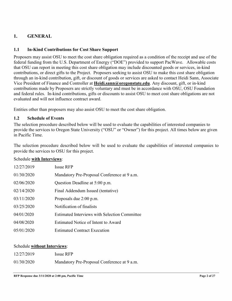
Figure 1 – PacWave Project Location Overview
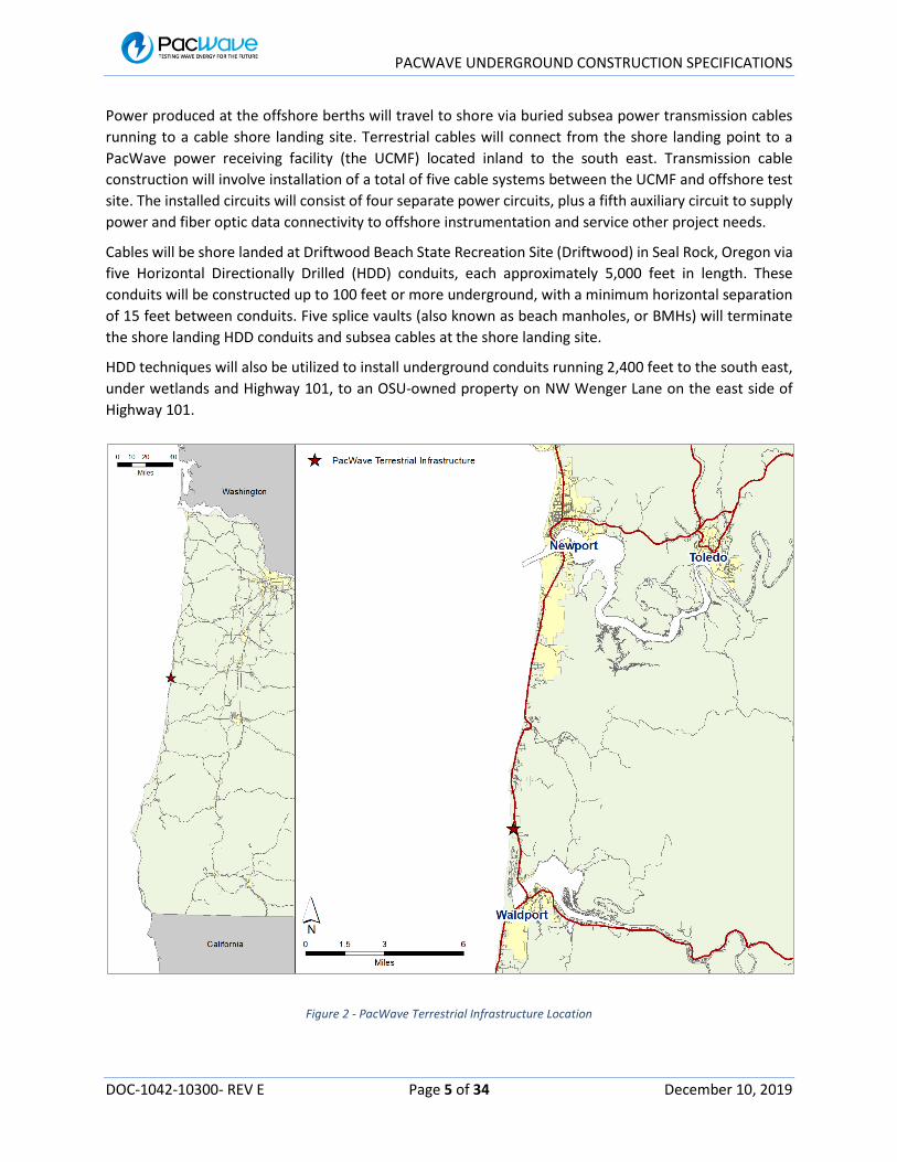
Power produced at the offshore berths will travel to shore via buried subsea power transmission cables running to a cable shore landing site. Terrestrial cables will connect from the shore landing point to a PacWave power receiving facility, the UCMF, located inland to the south east. Transmission cable construction will involve installation of a total of five cable systems between the UCMF and offshore test site. The installed circuits will consist of four separate power circuits, plus a fifth auxiliary circuit to supply power and fiber optic data connectivity to offshore instrumentation and service other project needs. Cables will be shore landed at Driftwood Beach State Recreation Site (“Driftwood”) in Seal Rock, Oregon via five HDD conduits, each approximately 5,000 feet in length. These conduits will be installed up to 100 feet or more underground, with a minimum horizontal separation of 15 feet between conduits.
Five splice vaults (also known as beach manholes or BMHs) will terminate the shore landing HDD conduits and subsea cables at the shore landing site.
HDD techniques will also be utilized to install underground conduits running 2,400 feet to the south east, under wetlands and Highway 101, to an OSU-owned property on NW Wenger Lane on the east side of Highway 101.
RFP Response due 3/11/2020 at 2:00 pm, Pacific Time Page 6 of 27
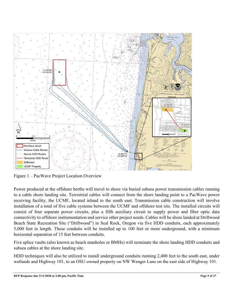
The proposed plan utilizes Driftwood as the underground cable landing and splicing location. The splice vaults (consisting of underground concrete vaults) will be installed in the Driftwood parking lot to serve as the subsea cable termination points. For each subsea cable, strength armor will be mechanically anchored within one of five splice vaults. Within each vault, the subsea cable power conductors and fiber optic cable elements will be permanently connected (spliced) to terrestrial power and fiber cables for onward transmission to the UCMF. From the UCMF, power will flow onto the CLPUD distribution grid via connection on the west side of Highway 101.
Figure 2 - PacWave Terrestrial Infrastructure Location

RFP Response due 3/11/2020 at 2:00 pm, Pacific Time Page 7 of 27
Figure 3: Driftwood Beach State Recreation Site with Bore Overlay
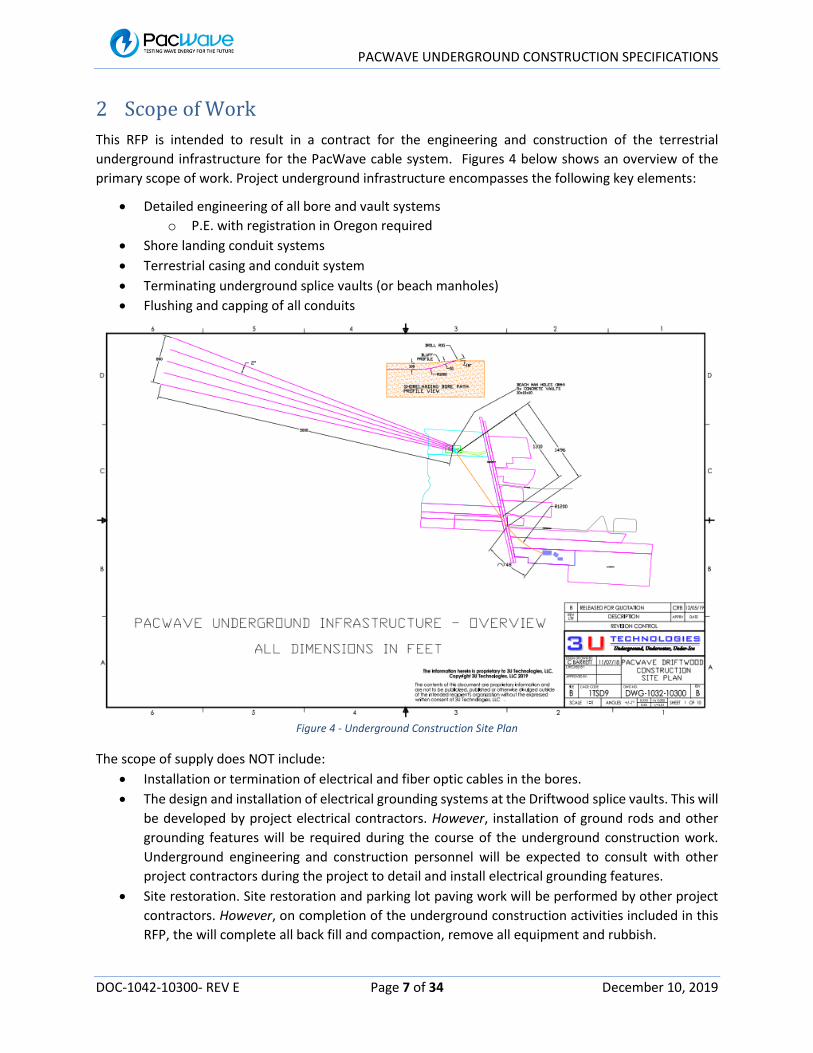
4.0 Scope of Work This RFP is intended to result in a Contract for the engineering and construction of the shore landing and terrestrial underground infrastructure for the PacWave cable system. Figure 4 below shows an overview of the primary scope of work as further detailed in Attachment A ‘Scope of Work’ (“the Work”). Project underground infrastructure encompasses the following key elements:
• Detailed engineering of all bore and vault systems o PE with registration in Oregon required
• Shore landing conduit systems • Terrestrial casing and conduit system • Terminating underground splice vaults (or beach manholes) • Flushing and capping of all conduits
RFP Response due 3/11/2020 at 2:00 pm, Pacific Time Page 8 of 27
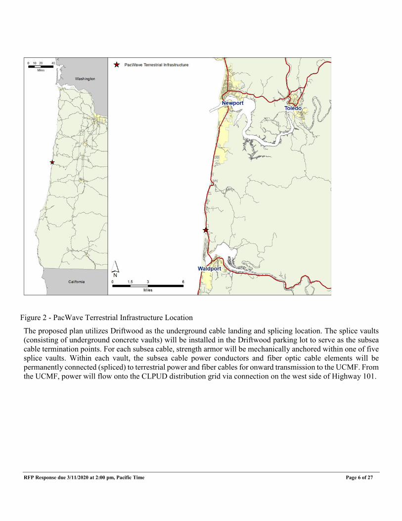
Figure 4: Underground Construction Site Plan Proposers must include all elements of the scope of work in their responses. Proposers who submit responses including only portions of the scope of work will be deemed non-responsive. The scope of work does NOT include:
• Installation or termination of electrical and fiber optic cables in the bores. • The design and installation of electrical grounding systems at the Driftwood splice vaults. • Site restoration and parking lot paving work will be performed by other project contractors. However,
upon completion of the underground construction activities included in this RFP, the contractor shall complete all back fill and compaction, and remove all equipment and rubbish.
4.1 Professional Engineer Stamped and Signed Documents Wherever a deliverable is identified as “Engineered” or “Stamped”, or any item is described as “Engineered”, the deliverable shall have been at a minimum reviewed, agreed to, signed and stamped by a professional engineer (“PE”) licensed in the state of Oregon. The PE signing a document shall be licensed and experienced in the appropriate branch of engineering for the deliverable. Where the PE experience is not directly relatable, a subject matter expert may review and sign the deliverable in addition to the PE sign off. The contractor shall provide full CVs (showing their experience/expertise in the area) for all PEs and subject matter experts who sign off on deliverables.

RFP Response due 3/11/2020 at 2:00 pm, Pacific Time Page 9 of 27
4.2 Shore Landing Construction Construction will involve demolition of the Driftwood parking lot to bore the shore landing conduits, installation of the splice vaults and installing terrestrial conduits. All construction work within park boundaries, but beyond the parking lot boundary, will involve underground construction via drilling or boring from the parking lot. Driftwood construction will involve the installation of underground infrastructure consisting of conduits and splice vaults.
4.3 Driftwood Splice Vault Construction
Proposers will be responsible for engineering, construction and installation of the five concrete splice vaults (or beach manholes, or BMHs) at Driftwood. There is one vault for each subsea cable. Each vault will be approximately 10 x 10 x 10 feet and will be buried below the surface of the parking lot. Each vault will be engineered to support normal roadway traffic loads. Each vault will be designed to support water-proof splices between one subsea cable and a matching terrestrial cable circuit.
4.4 Local Geology
Significant survey work in the area has been performed to date, including seismic surveys of most of the route, plus a recent core drilling. The results of these surveys generally fit the typical geology of the area and form the basis for the present assumptions of geology for all drilling routes. Detailed reports of seismic and geotechnical coring investigations to date are included in Attachment A.
5.0 General Project Constraints
5.1 Timeline and Sequencing
Underground construction sequencing will be dependent on Project scheduling. Proposer may elect to perform shore landing work between the months of April and September to take advantage of seasonal conditions more typical of calm seas that facilitate any marine and diving support requirements at the offshore breakout points. However, this is not a requirement.
The terrestrial boring work can be performed at any time, without regards to sea conditions. Therefore, depending on overall project scheduling, the initial Work element may or may not be the shore landing effort.
5.2 Habitat Protection
Habitat protection during construction is important to OSU. Driftwood is home to the extremely rare Seaside Hoary Elfin butterfly, which is closely associated with the kinnikinnick (or Bearberry) host plant. Therefore, all construction work within the state park boundary, must occur within the footprint of the existing parking lot. Any construction outside the parking lot footprint must employ underground construction methods (i.e. drilling or boring from within the parking lot footprint). Therefore, no revegetation is expected outside the parking lot boundaries. Impacts to kinnikinnick must be avoided.
RFP Response due 3/11/2020 at 2:00 pm, Pacific Time Page 10 of 27
5.3 Noise Limitations
The contractor must adhere to all applicable regulations regarding noise. There are multiple private residences around the Driftwood worksite, with the closest located approximately 250 feet to the north of the parking lot. It is critical that the maximum sound pressure level of the construction work should not impact nearby residences. Experience has shown that equipment generating 90 dBA at 10 feet did not cause disturbance at the nearest residences. If excessive noise will be required to complete the construction work, sound screening/barriers will be required to limit the impact. Construction operations are limited to daylight hours. Weekend construction activity is allowable.
5.4 Disposal
The contractor shall be responsible for disposal of all spoils and drilling mud from construction. The Contractor must adhere to all applicable regulations, including but not limited to hazardous waste, in the event that hazardous waste is produced or encountered as part of the construction activities.
Spoils from HDD and other construction operations cannot be disposed of on site and will likely need to be disposed of at an approved, Department of Environmental Quality (“DEQ”)-regulated, upland location. If a non DEQ-regulated upland disposal area is to be used, a Solid Waste Letter of Authorization or a Beneficial Use Determination must be secured from DEQ, if required.
NOTE: The water used during the rock coring operations, prior to boring operations, may be filtered to remove sand and silt-sized particles and infiltrated back into the ground, on site, if this can be achieved without impacting local wetlands or kinnikinnick habitat.
5.5 Schedule
Between January and February of 2020, OSU anticipates a formal determination from DOE to proceed to the construction phase. Notice to Proceed is contingent on OSU receiving formal approval from DOE to proceed with the construction phase. If DOE’s discretion is to not proceed to the construction phase of this Project, OSU reserves the right to terminate the Contract with the awarded contractor.
All necessary state and Federal permits and licenses for the project are expected to be in-hand by June, 2020 and Federal funds for construction will not be released until this time. OSU will be responsible for obtaining all permits. Awarded contractor is responsible to provide any information needed by OSU to and obtain those permits.
OSU anticipates a Notice to Proceed to be issued not later than February 2021. An earlier notice to proceed could occur as early as June 2020. Work is expected to begin at the time of the issuance of a Notice to Proceed, or as otherwise negotiated with OSU, and work must be completed within ten consecutive months.

RFP Response due 3/11/2020 at 2:00 pm, Pacific Time Page 11 of 27
6.0 Prevailing Wage In compliance with Oregon Prevailing Wage Law, the following is incorporated into this RFP:
The Contractor and all sub-contractors shall comply with the provisions of ORS 279C.800 through 279C.870, relative to Prevailing Wage Rates. The contract is subject to the following Bureau of Labor and Industries (“BOLI”) wage rate requirements, which are incorporated herein by reference:
• July 1, 2019 PWR Apprenticeship Rates • July 1, 2019 Prevailing Wage Rates for Public Works Contracts in Oregon • July 1, 2018 Definitions of Covered Occupations for Public Works Contracts in Oregon
These BOLI wage rates are available on line at:
https://www.oregon.gov/boli/WHD/PWR/Pages/pwr_state.aspx
Prior to execution of a contract, the Contractor shall file with the Construction Contractor’s Board, and maintain in full force and effect, the separate public works bond required by Oregon Laws 2015, ORS 279C and OAR 839-025-015, unless otherwise exempt under those provisions. The contractor shall also include in every subcontract a provision requiring the sub-contractor to have a public works bond filed with the Construction Contractor’s Board before starting services, unless otherwise exempt, and shall verify that the sub-contractor has filed a public works bond before permitting any sub-contractor performing services to start Work.
7.0 Evaluation and Selection 7.1 Evaluation
This RFP evaluation and selection process will be conducted pursuant to the terms of this RFP and OSU Standards 03-010 and 03-015. Selection of a Contractor will be based on the criteria set forth in this RFP.
Stages of Evaluation are as follows:
a. Determination of Responsiveness:
Proposals that do not comply with the instructions, that are materially incomplete, that do not meet the minimum requirements, or that are submitted by Proposers that do not meet minimum qualifications may be deemed non-Responsive.
b. First Stage Evaluation: Those Proposals determined to be Responsive will be evaluated based on the evaluation criteria contained herein.
OSU reserves the right to ask follow-up questions of Proposers during first stage evaluations. The questions will be for the purpose of clarification of information already contained in proposals and will not be an opportunity to submit additional documentation or change existing documentation. OSU may negotiate or request a Best and Final Offer after the first stage evaluation from the top scoring Proposer without moving on to the second stage evaluation.

RFP Response due 3/11/2020 at 2:00 pm, Pacific Time Page 12 of 27
c. Second Stage Evaluation:
If an award is not made after the first stage evaluation, Proposers within the competitive range will undergo a second stage evaluation under one or more of the following methods:
• Issue a written invitation to Proposers within the competitive range with instructions regarding an
interview/presentation. Written invitations will contain the evaluation criteria and scoring.
• OSU may negotiate or request Best and Final Offers with those Proposers within the competitive threshold.
Points awarded in the first stage evaluation will not be carried to the second stage evaluation. If a second stage evaluation of all Proposers does not produce an award that is in OSU’s best interest, OSU may return to the first stage evaluation to advance additional Proposers to a second stage evaluation.
7.2 Evaluation Criteria
Points will be given in each criteria and a total score will be determined. The maximum points available for each criterion and a description of each criterion are identified below.
Stage 1 Evaluation Criteria Points
Experience and Capabilities 20 Qualifications 15 Capacity and Current Projects 10 Method, Approach and Equipment 30 Schedule of Operations 15 Cost 40 June 2020 (10 Points) February 2021 (30 Points) Total (40 Points) Workforce Diversity Plan 15 References (Optional) 10 Stage 2 Evaluation Criteria Points Interviews 50 References (Optional) 10 _________________________________________________
RFP Response due 3/11/2020 at 2:00 pm, Pacific Time Page 13 of 27
Stage 1 Evaluation Criteria:
1. Experience and Capabilities Provide information about your firm’s experience and capabilities in performing the specific type of work described in this RFP and your experience working in Oregon, and your experience working in similar geologic and coastal conditions as found at the work site. Identify any projects you have undertaken in the region (e.g. Oregon coast). Provide a brief summary of three or more underground construction projects similar to that described in this RFP, that your company has completed or are currently contracted to complete, including methods of execution and the equipment being used. Include experience for similar services on federally funded projects. Include similar information for all sub-contractors.
2. Qualifications Provide a brief description of your firm and your firm’s overall qualifications related to the description of services sought in this RFP. Provide an organization chart with names, title, and job classification of personnel and identify key personnel, along with sub-contractor key personnel as applicable, to be assigned to the Scope in this Project. Please provide percentage of time allocated for each team member assigned. Include proposed key personnel’s CV or resumes including their project experience and identify their roles in similar projects. If different personnel are to be involved in specific phases of the survey work, those personnel shall be listed separately. Indicate current availability and proposed percentage of involvement for this Scope and whether the proposed team has worked together on previous projects.
3. Capacity and Current Projects List the projects your firm is currently contracted for and at what stage the projects are, in terms of completion. Provide similar information for any sub-contractors.
4. Method, Approach and Equipment Provide methodology describing how each item in Attachment A ‘Scope of Work’ will be implemented. The methodology must highlight different approaches or standards, if any, that proposer recommends for different aspects of the Scope. Proposers are encouraged to offer innovative solutions to completion of the work scope within the required time frame of ten months. Provide details and specifications of the proposed drilling rig and other equipment to be used for the Scope. The equipment proposed shall be that which the contractor considers appropriate to the requirements as described in the Scope of Work section (Attachment A). Manufacturer brochures should be included as supporting information. If different equipment will be used at different locations, these shall be specified separately.
RFP Response due 3/11/2020 at 2:00 pm, Pacific Time Page 14 of 27
5. Schedule of Operations Provide a proposed schedule of operation to successfully complete the work, during the specified time period as shown in Section 5.1 ‘Timeline and Sequencing’ and Section 5.5 ‘Schedule’. Proposer shall provide two schedules of operations based on the two potential dates for Notice to Proceed:
• June 2020 Notice to Proceed
• February 2021 Notice to Proceed
The schedule of operations shall include:
• Equipment and Crew Mobilization to Site
• Site Preparations at Driftwood
• Completion of Shore Landing Construction (including expected duration of each of the five seaward bores)
• Completion of Terrestrial Back Haul Construction
• Completion of Splice Vault Installation
• Site Clean Up
• Equipment and Crew Demobilization Additionally, Proposer should identify assumptions used to develop the schedule, including, but not limited to:
• Number of drilling per bore
• Number of weather/standby days
• Number of drill rigs
• Number of days on/days off in a typical work week
• Number of hours per day
6. Cost Provide two completed Attachment C ‘Cost Proposal’ one for each of the two schedule of operations based on the two potential dates for Notice to Proceed, June 2020 (10 Points) Notice to Proceed ; and February 2021 Notice to Proceed (30 Points). Both completed Cost Proposals shall be submitted with the proposal to be considered Responsive.
RFP Response due 3/11/2020 at 2:00 pm, Pacific Time Page 15 of 27
Formula for scoring Cost Points will be as follows: Lowest Cost for each of the price related items will receive full points with higher cost price related items receiving proportionally lower points according to this formula: (Low Cost / Cost) x Points Available. This Cost Proposal will become the initial contract amount for the awardee with additional services being added via amendment if/when applicable. In the event of a discrepancy between unit prices and extended (arithmetically calculated) prices, unit prices will prevail over extended prices.
7. Workforce Diversity Plan Provide a description and identification of Minority Business Enterprise (“MBE”), Women Business Enterprise (“WBE”) or Emerging Small Business (“ESB”) certifications for your firm and a description of your firm’s nondiscrimination practices. Provide any historical information on MBE, WBE or ESB Joint Ventures, subcontracting or mentoring plan, and utilization history for projects completed within the past three years. Provide a narrative description of your current workforce diversity program or plan, and the plan for obtaining subcontracting and consulting diversity for this project. The contractor shall perform the work and the contract with respect to diversity according to the means and methods described in its workforce plan described in the response, unless changes are requested and approved in writing in advance by OSU or are required by applicable laws, ordinances, codes, regulations, rules or standards.
8. Reference Checks – Optional OSU reserves the right to check the references provided by the Proposer as required by this RFP at any or each stage of evaluation.
Stage 2 Evaluation Criteria: 1. Interviews
Interviews will be conducted to aid in determining the Apparent Successful Proposer. Information regarding the Interviews will be provided to those firms in the Competitive Range following the initial review and scoring. If applicable, final scoring of the Interviews will be separate and not cumulative from the short-listing. Interviews will be prepared based on RFP responses and include a 30 minute presentation period immediately followed by a separate 30 minute question and answer period. Specific interview questions will be provided at the time of notification.
2. Reference Checks – Optional (10 Points) If not checked during the Stage 1 Evaluation process.

RFP Response due 3/11/2020 at 2:00 pm, Pacific Time Page 16 of 27
OSU reserves the right to check the references provided by the Proposer as required by this RFP at any stage of evaluation.
7.3 Investigation of References
In addition to responding to the evaluation criteria above, provide the names, addresses, email address and telephone numbers of three professional references for work performed by your company on similar projects using the form in Attachment B ‘References.’ At minimum one reference provided shall be related to a project described in the Experience and Capabilities section of the proposal. Verify that the individuals identified have had direct involvement with the referenced project, and the email address and telephone number are current. Do not include references from any company or individual included in your team for this project, or any OSU personnel. OSU may check with these references and with other references associated with past work of your company. Reference checks may occur during any stage of evaluation. If the evaluation committee determines the interviewed finalists are too close to score, OSU has no recent experience working with a finalist, or if the consolidated scoring indicates a tie, the evaluation committee will check the references provided by the Proposer as required by this RFP in Attachment B ‘References.’ Information obtained from references will be used in the evaluation committee’s final scoring and will be based on the evaluation committee’s understanding of how well each firm can meet the needs of OSU.
7.4 Negotiations
OSU may commence negotiations with the top scoring Proposer or commence simultaneous negotiations with all Responsive Proposers within the competitive range. OSU may negotiate:
• The Statement of Work; • The Contract price as it is affected by negotiating the Statement of Work; and • Any other terms and conditions as determined by OSU.
7.5 Contract Award
a. A Sample Contract will be added by addendum at a later date. b. Any/all exceptions to the Terms and Conditions included in the Sample Contract (including General
Conditions) shall be clearly identified and appended to the Proposal in order to be considered by OSU during the negotiation period following selection of the Apparent Successful Proposer.
8.0 Reserved
9.0 Responsibility Evaluation OSU reserves the right to investigate each proposer’s responsibility in accordance with the requirements of the Oregon State University Standards, and will consider information obtained from any source as part of its evaluation, at any time prior to execution of a contract. Submission of a signed proposal response constitutes the
RFP Response due 3/11/2020 at 2:00 pm, Pacific Time Page 17 of 27
proposer’s approval for OSU to obtain any information OSU deems necessary to conduct the evaluation including, but not limited to, credit reports and information discovered during reference checks.
Financial Information: OSU will notify proposers, in writing, of any financial documentation required, which may include recent profit-and-loss history; current balance statements; assets-to-liabilities ratio, including number and amount of secured versus unsecured creditor claims; availability of short and long-term financing; bonding capacity and credit information.
OSU may postpone the award or execution of a contract in order to complete its investigation and evaluation. Failure to promptly provide complete information requested may render the proposal response nonresponsive. Failure of a proposer to demonstrate responsibility will render it non-responsible and constitute grounds for proposal response rejection.
10.0 Submission 10.1 Each Proposal shall be sealed in an envelope, properly addressed to the Contract Administrators, showing on the outside of the envelope the name of the Proposer and the title of the RFP. Submit one hard copy version of your written proposal response, along with one electronic version on a thumb drive to be received by the closing date and time listed in this document to:
Attention: Hanna Emerson & Ben Baggett Construction Contracts Administration
Oregon State University 644 SW 13th Street
Corvallis, OR 97333-4238
Your proposal response must be contained in a document not to exceed twenty-five single sided pages including the Attachment C ‘Cost Proposal’ pricing sheet, pictures, charts, graphs, tables and text the proposer deems appropriate to be part of the review of the proposer’s response. C V ’ s o r Resumes of key individuals proposed to be involved in this project are exempted from the twenty-five page limit and should be appended to the end of your response. No supplemental information to the twenty-five page proposal response will be allowed. Appended C V ’ s o r resumes of the proposed key individuals, along with a transmittal letter, table of contents, front and back covers, and blank section/numerical dividers, etc., will not be counted in the twenty-five page limit.
Information should be presented in the same order as the above evaluation criteria. The electronic proposal response should be sized appropriately for transfer (under 8 MB). The written response should be submitted in a soft-bound (comb or spiral, spiral preferred – no three-ring binders) format with page size of 8 ½ x 11 inches with no fold-outs. The basic text information of the response should be presented in standard business font size, and reasonable margins. All information provided should be included in both written and electronic submittals.
Your proposal response must be signed by an authorized representative of your company with the authority to bind the Proposer and contain contact information including email for communication purposes. Signature certifies that the Proposer has read, fully understands, and agrees to be bound by the

RFP Response due 3/11/2020 at 2:00 pm, Pacific Time Page 18 of 27
Request for Proposal and all Exhibits and Addenda to the Request for Proposal. OSU may reject any proposal not in compliance with all applicable OSU solicitation procedures and requirements, and may cancel this solicitation or reject for good cause, all proposals upon a finding by OSU that it is in the public interest to do so.
Note that OSU will not accept proposal responses or queries that require OSU to pay the cost of production or delivery.
Telephone, facsimile, or electronically transmitted submittals will not be accepted. Proposal responses received after the closing date and time will not be considered.
11.0 Instructions to Proposers 11.1 Applicable Statutes and Rules This Request for Proposal is subject to the applicable provisions and requirements of the Oregon Revised Statutes, Oregon Administrative Rules, and OSU Policies and Procedures. 11.2 Communication During the RFP Process In order to ensure a fair and competitive environment, direct communication between OSU employees, other than the Administrative Contact or other PCMM representative, and any party in a position to create an unfair advantage to Proposer or disadvantage to other Proposers with respect to the RFP process or the award of a Contract is strictly prohibited. This restricted period of communication begins on the issue date of the solicitation and for Proposer(s) not selected for award ends with the conclusion of the appeals period identified in OSU Standard 03-015, Sec. 5.20.8(b) and for Proposers(s) selected for award ends with the Contract Execution. This restriction does not apply to communications to other OSU employees during a Pre-Proposal conference or other situation where the Administrative Contact has expressly authorized direct communications with other staff. A Proposer who intentionally violates this requirement of the RFP process or otherwise deliberately or unintentionally benefits from such a violation by another party may have its Proposal rejected due to failing to comply with all prescribed solicitation procedures. The rules governing rejection of individual solicitation responses and potential appeals of such rejections are at OSU Standard 03-015, Sec. 5.20. 11.3 Manufacturer’s Names and Approved Equivalents Unless qualified by the provision "NO SUBSTITUTE" any manufacturers' names, trade name, brand names, information and catalog numbers listed in a specification are for information and not intended to limit competition. Proposers may offer any brand for which they are an authorized representative, which meets or exceeds the specification for any item(s). If Proposals are based on equivalent products, indicate in the Proposal form the manufacturers' name and number. Proposers shall submit with their Proposal, sketches, and descriptive literature, and complete specifications. Reference to literature submitted with a previous Proposal will not satisfy this provision. Proposers shall also explain in detail the reason(s) why the proposed equivalent will meet the specifications and not be considered an exception thereto. Proposals that do not comply with these requirements are subject to rejection. Proposals lacking any written indication of intent to provide an alternate brand will be received and considered in complete compliance with the specification as listed in the RFP.
RFP Response due 3/11/2020 at 2:00 pm, Pacific Time Page 19 of 27
11.4 Requests for Clarification or Change Requests for clarification or change of the RFP must be in writing and received by the Contract Administrator no later than the Question Deadline. Such requests for clarification or change must include the reason for the Proposer’s request. OSU will consider all timely requests and, if acceptable to OSU, amend the RFP by issuing an Addendum. Envelopes, e-mails or faxes containing requests must be clearly marked as a ‘Request for Clarification or Change’ and include the RFP Title. 11.5 Addenda Only documents issued as written Addenda by PCMM serve to change the Request for Proposal in any way. No other direction received by the Proposer, written or verbal, serves to change the RFP. Addenda will be publicized on the OSU procurement website. Proposers are advised to consult the OSU procurement website prior to submitting a Proposal in order to ensure that all relevant Addenda have been incorporated into the Proposal. Proposers are not required to submit Addenda with their Proposal. However, Proposers are responsible for obtaining and incorporating any changes made by Addenda into their Proposal. Failure to do so may make the Proposal non-Responsive, which in turn may cause the Proposal to be rejected. 11.6 Public Record Upon completion of the Request for Proposal process, information in all Proposals will become subject records under the Oregon Public Records Law. Only those items considered a “trade secret” under ORS 192.501(2), may be exempt from disclosure. If a Proposal contains what the Proposer considers a “trade secret” the Proposer must mark each sheet of information as such. Only bona fide trade secrets may be exempt and only if public interest does not require disclosure. 11.7 Proprietary Information and Trade Secret If a proposal response contains any information that you consider to be a trade secret under ORS 192.501(2), you must mark each trade secret with the following legend: "This data constitutes a trade secret under ORS 192.501(2), and must not be disclosed except in accordance with the Oregon Public Records Law, ORS Chapter 192." The Oregon Public Records Law exempts from disclosure only bona fide trade secrets, and the exemption from disclosure applies only "unless the public interest requires disclosure in the particular instance."
Therefore, non-disclosure of documents or any portion of a document submitted as part of a proposal response may depend upon official or judicial determination made pursuant to the Public Records Law.
In order to facilitate public inspection of the non-confidential portion of the proposal response, material designated as confidential must accompany the proposal response, but must be readily separable from it. Prices, makes, model or catalog numbers of items offered, scheduled delivery dates, and terms of payment will be publicly available regardless of any designation to the contrary.
11.8 Modification Prior to submittal, Proposers should initial modifications or erasures in ink by the person signing the Proposal. After submittal but prior to the Closing, Proposals may be modified by submitting a written notice indicating the modifications and a statement that the modification amends and supersedes the prior Proposal. After the Closing, Proposers may not modify their Proposal.

RFP Response due 3/11/2020 at 2:00 pm, Pacific Time Page 20 of 27
11.9 Withdrawals A Proposer may withdraw their Proposal by submitting a written notice to the Administrative Contact identified in this Request for Proposal prior to the Closing. The written notice must be on the Proposer’s letterhead and signed by an authorized representative of the Proposer. The Proposer, or authorized representative of the Proposer, may also withdraw their Proposal in person prior to the Closing, upon presentation of appropriate identification and evidence of authority to withdraw the Proposal satisfactory to OSU. 11.10 Execution of Contract, Agreement, Performance Bond and Payment Bond The Proposer shall be required to execute the Contract as provided, and, if applicable, deliver a Performance Bond and a Payment Bond from a surety company licensed to do surety business in the State of Oregon within time period contained in the Award letter. The Contract Documents shall be delivered to the OSU in the manner stated in the Award letter. If awarded the Contract, Contractor shall deliver to OSU, a satisfactory Performance Bond and Payment Bond, each in an amount equal to one hundred (100) percent of the Contract sum, using forms provided by OSU as shown in Attachment E ‘Performance and Payment Bond.’ 11.11 Late Submittals Proposals and written notices of modification or withdrawal must be received no later than the Closing (in the case of electronic submissions, the time/date stamp of the email received at the PCMM office must be no later than the Closing). OSU may not accept or consider late Proposals, modifications, or withdrawals except as permitted in OSU Standard 03-015, Sec 5.9. Sole responsibility rests with the Proposer to ensure OSU’s receipt of its Proposal prior to the Closing. OSU shall not be responsible for any delays or misdeliveries caused by common carriers or by transmission errors, malfunctions, or electronic delays. Any risks associated with physical delivery or electronic transmission of the Proposal are borne by the Proposer. 11.12 Proposals are Offers The Proposal is the Proposer’s offer to enter into a Contract pursuant to the terms and conditions specified in the Request for Proposal, its Exhibits, and Addenda. The offer is binding on the Proposer for one hundred twenty (120) days. OSU’s award of the Contract constitutes acceptance of the offer and binds the Proposer. The Proposal must be a complete offer and fully Responsive to the Request for Proposal. 11.13 Contingent Proposals Proposer shall not make its Proposal contingent upon OSU’s acceptance of specifications or contract terms that conflict with or are in addition to those in the Request for Proposal, its Exhibits, or Addenda. 11.14 Right to Reject OSU may reject, in whole or in part, any Proposal not in compliance with the Request for Proposal, Exhibits, or Addenda, if upon OSU’s written finding that it is in the public interest to do so. OSU may reject all Proposals for good cause, if upon OSU’s written finding that it is in the public interest to do so. Notification of rejection of all Proposals, along with the good cause justification and finding of public interest, will be sent to all who submitted a Proposal. 11.15 Awards OSU reserves the right to make award(s) by individual item, group of items, all or none, or any combination

RFP Response due 3/11/2020 at 2:00 pm, Pacific Time Page 21 of 27
thereof. OSU reserves the right to delete any item from the award when deemed to be in the best interest of OSU. 11.16 Legal Review Prior to execution of any Contract resulting from this Request for Proposal, the Contract may be reviewed by a qualified attorney for OSU pursuant to the applicable Oregon State University Standards, Oregon Revised Statutes and Oregon Administrative Rules. Legal review may result in changes to the terms and conditions specified in the Request for Proposal, Exhibits, and Addenda. 11.17 Proposal Results A written notice of intent to award will be issued to all Proposers. The Proposal file will be available for Proposer’s review during the appeal period at the PCMM Department. Proposers must make an appointment with the Administrative Contact to view the Proposal file. After the appeal period, the file will be available by making a Public Records Request to OSU Office of General Counsel. 11.18 Proposal Preparation Cost OSU is not responsible for costs incurred by the Proposer during the Request for Proposal process. 11.19 Proposal Cancellation If a Request for Proposal is cancelled prior to the Closing, all Proposals that may have already been received will be returned to the Proposers. If a Request for Proposal is cancelled after the Closing or all Proposals are rejected, the Proposals received will be retained and become part of OSU’s permanent Proposal file. 11.20 Appeal of Contractor Selection, Contract Award Any Proposer who feels adversely affected or aggrieved may submit an appeal within three (3) business days after OSU issues a notice of intent to award a Contract. The appeal must be clearly identified as an appeal, identify the type and nature of the appeal, and include the Request for Proposal number and title. The rules governing appeals are at OSU Standard 03-015, Sec. 5.20. 11.21 Appeal of Solicitation Process You may submit a written request for clarification or change or appeal of particular solicitation provisions and specifications and contract terms and conditions (including comments on any specifications or terms that you believe limits competition) to the Chief Procurement Officer in care of Ben Baggett at the address, email or fax listed in this document. Requests and appeals must be received no later than seven days after the decisions or actions by OSU, as appropriate per Section 5.20 of the OSU Procurement Standards 03-015. Requests or appeals must state the reasons for the request or appeal and any proposed changes to the solicitation provisions and specifications and contract terms and conditions. Requested changes to contract terms and conditions may not be considered at contract award.
18.0 Termination of Agreement; Non-Availability of Funds
OSU reserves the right to terminate a project, the Contract, or both, at any time, upon thirty days’ written notice. Please see Attachment D - OSU Sample Contract section XVI. Termination of Agreement; Non-Availability of Funds. Note: Attachment D will be added by addendum at a later date.
RFP Response due 3/11/2020 at 2:00 pm, Pacific Time Page 22 of 27
19.0 Insurance Provisions
During the term of the resulting Agreement, the successful proposer will be required to maintain in full force, at its own expense, from insurance companies authorized to transact the business of insurance in the state of Oregon, each insurance coverage/policy as set forth in Attachment D: OSU Sample Contract. Note: Attachment D will be added by addendum at a later date.
RFP Attachments:
• Attachment A: Scope of Work
• Attachment B: References
• Attachment C: Cost Proposal
• Attachment D: OSU Sample Contract: Construction and Engineering Services
• Attachment E: Performance Bond, Payment Bond
RFP Appendices (attached as separate documents):
• 10.1a PacWave Driftwood Construction Site Plan – Rev B
• 10.1b Terrestrial Drilling Casing Assembly – Rev O
• 10.1c Shorelanding Single Cable Conduit Assembly
• 10.1d Proposed Earth Grounding System – Driftwood Grounding
• 10.1e Cable & Conduit Termination Vault – UCMF Terrestrial Vault
• 10.2a Driftwood Parking Lot Seismic Survey Report
• 10.2b HDD Seismic Survey Report – Rev O
• 10.2c PacWave Terrestrial Cable route Seismic Survey Report – Rev O
• 10.3a Draft Core Drilling Logs
End of RFP

RFP Response due 3/11/2020 at 2:00 pm, Pacific Time Page 23 of 27
Attachment A
Scope of Work

DOC-1042-10300
PACWAVE
UNDERGROUND CONSTRUCTION
SPECIFICATIONS
REV E
Release for RFP
December 10, 2019

PACWAVE UNDERGROUND CONSTRUCTION SPECIFICATIONS
DOC-1042-10300- REV E Page 2 of 34 December 10, 2019
Table of Contents ...................................................................................................................................................................... 1
1 Project Overview ................................................................................................................................... 4
2 Scope of Work ....................................................................................................................................... 7
2.1 Professional Engineer Stamped and Signed Documents .............................................................. 8
3 Shore Landing........................................................................................................................................ 9
3.1 Summary ....................................................................................................................................... 9
3.2 Five Bore Construction Plan .......................................................................................................... 9
3.3 Shore Landing Construction ........................................................................................................ 12
3.4 Driftwood BMH Construction ..................................................................................................... 14
3.5 Cable & Ground System .............................................................................................................. 14
4 Terrestrial Back Haul Bore .................................................................................................................. 15
4.1 Terrestrial Back Haul Construction Impediments ....................................................................... 17
4.2 Terrestrial Back Haul Casing Assembly ....................................................................................... 18
4.3 Terrestrial Back Haul Bore Plan ................................................................................................... 19
5 Grid Interconnect ................................................................................................................................ 22
6 Boring and Conduit Site Work Completion ......................................................................................... 23
6.1 Driftwood Underground Splice Vaults ........................................................................................ 23
6.1.1 Splice Vault Design & Construction ..................................................................................... 24
6.1.2 Splice Vault Ground system ................................................................................................ 24
6.1.3 Splice Vault Installation ....................................................................................................... 25
6.1.4 Interface of Splice Vaults with Shore Landing HDD Casings ............................................... 25
6.1.5 Mechanical Termination of Subsea Cable in the Splice Vaults ........................................... 25
6.1.6 Interface of Splice Vault with Terrestrial Conduits ............................................................. 25
6.1.7 Cable Vault Access .............................................................................................................. 26
6.2 UCMF Underground Cable Vault................................................................................................. 26
6.2.1 UCMF Cable Vault Ground System ..................................................................................... 26
7 Local Geology ...................................................................................................................................... 28
7.1 Driftwood Survey Findings .......................................................................................................... 28
7.2 Terrestrial Back Haul Route Geology .......................................................................................... 29
7.3 Route Surface Elevations ............................................................................................................ 30
8 Geotechnical Coring Investigation ...................................................................................................... 31
9 Project Requirements ......................................................................................................................... 32
PACWAVE UNDERGROUND CONSTRUCTION SPECIFICATIONS
DOC-1042-10300- REV E Page 3 of 34 December 10, 2019
9.1 Schedule ...................................................................................................................................... 32
9.2 Disposal ....................................................................................................................................... 32
9.3 Noise Limitations......................................................................................................................... 32
9.4 Restoration plan .......................................................................................................................... 33
10 Appendices ...................................................................................................................................... 34
10.1 Construction Plans ...................................................................................................................... 34
10.2 Seismic Survey ............................................................................................................................. 34
10.3 Geotechnical Core Drilling Survey ............................................................................................... 34
10.4 Project Schedule ......................................................................................................................... 34

PACWAVE UNDERGROUND CONSTRUCTION SPECIFICATIONS
DOC-1042-10300- REV E Page 4 of 34 December 10, 2019
1 Project Overview
Oregon State University (OSU) has partnered with the U.S. Department of Energy (DOE) and other
stakeholders to build a wave energy test facility located off Newport, Oregon called PacWave South
(PacWave). PacWave will be the Nation’s first grid-connected, pre-permitted wave energy test facility.
PacWave is funded and supported by DOE, the State of Oregon and various other public and private
entities. Construction is scheduled to commence in 2020. In addition to supporting the development of
new, clean energy technologies, this project will provide future power for local needs.
PacWave will be located in the Pacific Ocean, approximately 6 nautical miles off the coast south of
Newport, on the outer continental shelf (OCS) and will occupy an area of approximately two square
nautical miles. PacWave will feature four pre-permitted offshore test berths in 260 feet of water, each
featuring an individual power cable for transmission of up to 5 megawatts (MW) of electric power from
the test berth to a shore-based Utility Connection and Monitoring Facility (UCMF). At full capacity,
PacWave will have the potential to generate up to 20 MW of power and support up to 20 commercial-
scale wave energy converters (WECs) with resultant power transferred the Central Lincoln People’s Utility
District (CLPUD) electrical distribution system.
Figure 1 – PacWave Project Location Overview
PACWAVE UNDERGROUND CONSTRUCTION SPECIFICATIONS
DOC-1042-10300- REV E Page 5 of 34 December 10, 2019
Power produced at the offshore berths will travel to shore via buried subsea power transmission cables
running to a cable shore landing site. Terrestrial cables will connect from the shore landing point to a
PacWave power receiving facility (the UCMF) located inland to the south east. Transmission cable
construction will involve installation of a total of five cable systems between the UCMF and offshore test
site. The installed circuits will consist of four separate power circuits, plus a fifth auxiliary circuit to supply
power and fiber optic data connectivity to offshore instrumentation and service other project needs.
Cables will be shore landed at Driftwood Beach State Recreation Site (Driftwood) in Seal Rock, Oregon via
five Horizontal Directionally Drilled (HDD) conduits, each approximately 5,000 feet in length. These
conduits will be constructed up to 100 feet or more underground, with a minimum horizontal separation
of 15 feet between conduits. Five splice vaults (also known as beach manholes, or BMHs) will terminate
the shore landing HDD conduits and subsea cables at the shore landing site.
HDD techniques will also be utilized to install underground conduits running 2,400 feet to the south east,
under wetlands and Highway 101, to an OSU-owned property on NW Wenger Lane on the east side of
Highway 101.
Figure 2 - PacWave Terrestrial Infrastructure Location

PACWAVE UNDERGROUND CONSTRUCTION SPECIFICATIONS
DOC-1042-10300- REV E Page 6 of 34 December 10, 2019
The proposed plan utilizes Driftwood as the underground cable landing and splicing location. The splice
vaults (consisting of underground concrete vaults) will be installed in the Driftwood parking lot to serve
as the subsea cable termination point. For each subsea cable, strength armor will be mechanically
anchored within one of five splice vaults. Within each vault, the subsea cable power conductors and fiber
optic cable elements will be permanently connected (spliced) to terrestrial power and fiber cables for
onward transmission to the UCMF. From the UCMF, power will flow onto the Central Lincoln People’s
Utility District (CLPUD) distribution grid via connection on the west side of Highway 101.
Figure 3 - Driftwood Beach State Recreation Site with Bore Overlay
PACWAVE UNDERGROUND CONSTRUCTION SPECIFICATIONS
DOC-1042-10300- REV E Page 7 of 34 December 10, 2019
2 Scope of Work
This RFP is intended to result in a contract for the engineering and construction of the terrestrial
underground infrastructure for the PacWave cable system. Figures 4 below shows an overview of the
primary scope of work. Project underground infrastructure encompasses the following key elements:
Detailed engineering of all bore and vault systems
o P.E. with registration in Oregon required
Shore landing conduit systems
Terrestrial casing and conduit system
Terminating underground splice vaults (or beach manholes)
Flushing and capping of all conduits
Figure 4 - Underground Construction Site Plan
The scope of supply does NOT include:
Installation or termination of electrical and fiber optic cables in the bores.
The design and installation of electrical grounding systems at the Driftwood splice vaults. This will
be developed by project electrical contractors. However, installation of ground rods and other
grounding features will be required during the course of the underground construction work.
Underground engineering and construction personnel will be expected to consult with other
project contractors during the project to detail and install electrical grounding features.
Site restoration. Site restoration and parking lot paving work will be performed by other project
contractors. However, on completion of the underground construction activities included in this
RFP, the will complete all back fill and compaction, remove all equipment and rubbish.

PACWAVE UNDERGROUND CONSTRUCTION SPECIFICATIONS
DOC-1042-10300- REV E Page 8 of 34 December 10, 2019
2.1 Professional Engineer Stamped and Signed Documents
Wherever a deliverable is identified as “Engineered” or “Stamped”, or any item is described as
“Engineered”, the deliverable shall have been at a minimum reviewed, agreed to, signed and stamped by
a professional engineer (PE) licensed in the state of Oregon. The PE signing a document shall be licensed
and experienced in the appropriate branch of engineering for the deliverable. Where the PE experience
is not directly relatable, a subject matter expert may review and sign the deliverable in addition to the PE
sign off. The contractor shall provide full CVs (showing their experience/expertise in the area) for all PEs
and subject matter experts who sign off on deliverables.

PACWAVE UNDERGROUND CONSTRUCTION SPECIFICATIONS
DOC-1042-10300- REV E Page 9 of 34 December 10, 2019
3 Shore Landing
3.1 Summary
As a wave energy facility, the planned project location was chosen based on the high energy wave
environment immediately offshore. While sea conditions are significantly calmer between April and
September, marine support costs and weather delays hold the potential for high costs and significant cost
over runs during construction if the operations are dependent on marine support. Budgetary review of
marine support costs and potential for weather delays has resulted in a preferred construction plan
featuring five shore landing bores, sleeved via push/wash in construction to minimize marine support
requirements.
3.2 Five Bore Construction Plan
The preferred shore landing plan involves construction of five individual bores, drilled using HDD methods
and lined with steel conduit, running from the parking lot of Driftwood. Initially, each bore would be drilled
sufficiently oversized (nominally expected as 12-3/4 inch diameter) using the shore based drill rig without
extensive offshore marine support. On completion of break out offshore, 6-3/8 inch minimum clear ID,
steel conduit would be installed by push/wash over from the shore based drill rig. The conduit OD will be
finalized during detail bore design by the project contractor team, subject to PacWave review and
concurrence, but is expected to require 7 to 8 inch threaded steel or Permaloc (or equivalent) casing (7-
5/8 or 8-5/8 inch OD). The conduit will require an appropriate coating (Epoxy or concrete) suitable to
provide a 25-year life rating in the salt water environment in which this project will be installed.
One subsea cable will run through each underground steel conduit, installed using HDD, from the parking
lot of Driftwood. To meet the project scheduling requirements (detailed further within), it is expected that
two drilling rigs will be required on site, drilling bores simultaneously.
Figure 5 shows the general configuration of the shore landing conduit assembly as envisioned. Figures 6
and 7 show the general layout of splice vaults and shore landing bore alignments.

PACWAVE UNDERGROUND CONSTRUCTION SPECIFICATIONS
DOC-1042-10300- REV E Page 10 of 34 December 10, 2019
Figure 5 - HDD Installed Conduit Assembly
Figure 6 - Splice Vault (or BMH) Locations at Driftwood
PACWAVE UNDERGROUND CONSTRUCTION SPECIFICATIONS
DOC-1042-10300- REV E Page 11 of 34 December 10, 2019
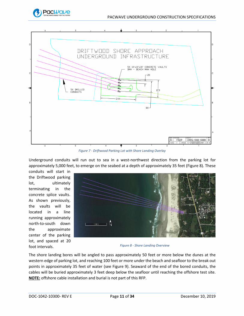
Figure 7 - Driftwood Parking Lot with Shore Landing Overlay
Underground conduits will run out to sea in a west-northwest direction from the parking lot for
approximately 5,000 feet, to emerge on the seabed at a depth of approximately 35 feet (Figure 8). These
conduits will start in
the Driftwood parking
lot, ultimately
terminating in the
concrete splice vaults.
As shown previously,
the vaults will be
located in a line
running approximately
north-to-south down
the approximate
center of the parking
lot, and spaced at 20
foot intervals.
The shore landing bores will be angled to pass approximately 50 feet or more below the dunes at the
western edge of parking lot, and reaching 100 feet or more under the beach and seafloor to the break out
points in approximately 35 feet of water (see Figure 9). Seaward of the end of the bored conduits, the
cables will be buried approximately 3 feet deep below the seafloor until reaching the offshore test site.
NOTE: offshore cable installation and burial is not part of this RFP.
Figure 8 - Shore Landing Overview

PACWAVE UNDERGROUND CONSTRUCTION SPECIFICATIONS
DOC-1042-10300- REV E Page 12 of 34 December 10, 2019
The landward end of each subsea cable will enter buried splice vaults via the steel conduits. Inside each
vault, these subsea cables will be mechanically anchored to the vault. Subsea cable conductors and fiber
elements will be permanently connected (spliced) to terrestrial cables for onward transmission to the
UCMF (by other project contractors). Extra cable length will be stored in the vaults as part of the
termination process.
3.3 Shore Landing Construction
Construction will involve demolition of the Driftwood parking lot to bore the shore landing conduits,
installation of the splice vaults and installing terrestrial conduits. All construction work within park
boundaries, but beyond the parking lot boundary, will involve underground construction via drilling or
boring from the parking lot. Driftwood construction will involve installation of underground infrastructure
consisting of conduits and splice vaults.
Underground construction sequencing will be dependent on project scheduling. Shore landing work likely
will need to occur between the months of April and September months to allow for any marine and diving
support requirements at the offshore break out points. On the other hand, terrestrial boring work can be
performed at any time, without regards to sea conditions. Therefore, depending on overall project
scheduling, the initial work element may or may not be the shore landing effort.
A notional list of equipment and materials required to support shore landing HDD construction includes
the following, as illustrated in Figures 10 and 11:
1-2 ea. drilling rig – semi trailer, 64 x 8 foot
1-2 ea. control cab – 20 x 8 foot
1-2 ea. pipe rack – 40 x 8 foot
2-4 ea. power units (generators) – 20 x 8 foot
Figure 9 - Profile View of Typical Shore Landing Bore

PACWAVE UNDERGROUND CONSTRUCTION SPECIFICATIONS
DOC-1042-10300- REV E Page 13 of 34 December 10, 2019
1 ea. cherry picker or mobile crane
1 ea. combination backhoe / front end loader
4 ea. 64 x 8-foot trailers - mud pump & control system
1 ea. tool trailer – 40 x 8 foot
2 ea. 30 x 20-foot area for storage of drilling Bentonite
2 ea. 40-yard dumpsters
Figure 10 - Construction Site Layout – Dual Rig Operation
Figure 11 - Construction Site Layout - Zoom
PACWAVE UNDERGROUND CONSTRUCTION SPECIFICATIONS
DOC-1042-10300- REV E Page 14 of 34 December 10, 2019
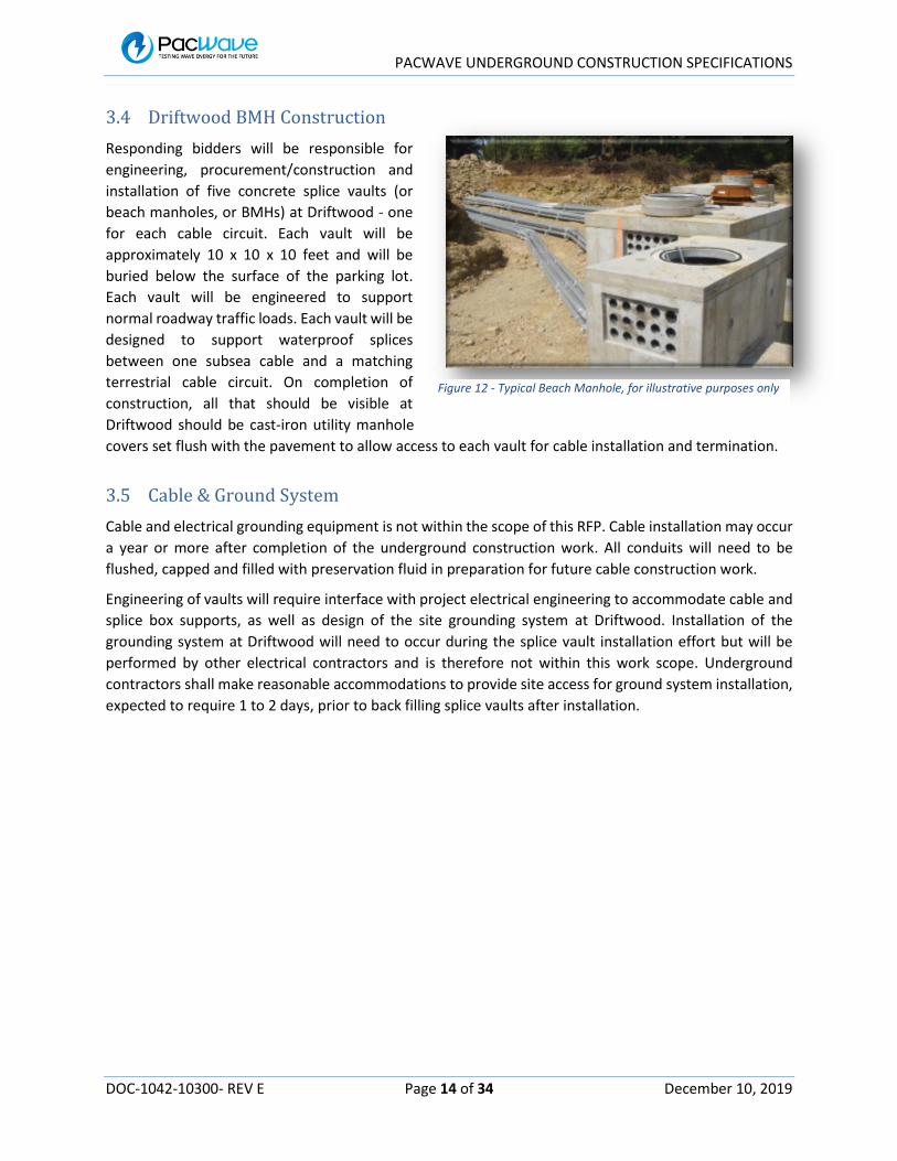
3.4 Driftwood BMH Construction
Responding bidders will be responsible for
engineering, procurement/construction and
installation of five concrete splice vaults (or
beach manholes, or BMHs) at Driftwood - one
for each cable circuit. Each vault will be
approximately 10 x 10 x 10 feet and will be
buried below the surface of the parking lot.
Each vault will be engineered to support
normal roadway traffic loads. Each vault will be
designed to support waterproof splices
between one subsea cable and a matching
terrestrial cable circuit. On completion of
construction, all that should be visible at
Driftwood should be cast-iron utility manhole
covers set flush with the pavement to allow access to each vault for cable installation and termination.
3.5 Cable & Ground System
Cable and electrical grounding equipment is not within the scope of this RFP. Cable installation may occur
a year or more after completion of the underground construction work. All conduits will need to be
flushed, capped and filled with preservation fluid in preparation for future cable construction work.
Engineering of vaults will require interface with project electrical engineering to accommodate cable and
splice box supports, as well as design of the site grounding system at Driftwood. Installation of the
grounding system at Driftwood will need to occur during the splice vault installation effort but will be
performed by other electrical contractors and is therefore not within this work scope. Underground
contractors shall make reasonable accommodations to provide site access for ground system installation,
expected to require 1 to 2 days, prior to back filling splice vaults after installation.
Figure 12 - Typical Beach Manhole, for illustrative purposes only

PACWAVE UNDERGROUND CONSTRUCTION SPECIFICATIONS
DOC-1042-10300- REV E Page 15 of 34 December 10, 2019
4 Terrestrial Back Haul Bore
In addition to the bored shore landings, terrestrial back haul cable casing and conduits will be installed via
HDD boring to the south east, towards the UCMF property, as shown on Figure 13. The terrestrial back
haul underground construction will involve drilling a single bore from the Driftwood parking lot, passing
under a wetland system to the south east, under a number of private parcels and under Highway 101 to
the PacWave UCMF property. The total route distance of this bore will be approximately 2,200 feet.
Figure 13 - Terrestrial Route Overview
After completion of drilling, the back haul bore will be back reamed and a 30-inch HDPE casing with seven
internal conduits will be pulled in from the south to the north (i.e. from the UCMF to Driftwood). It is
PACWAVE UNDERGROUND CONSTRUCTION SPECIFICATIONS
DOC-1042-10300- REV E Page 16 of 34 December 10, 2019
expected that the same drilling rig, support equipment and consumables that will be used for the shore
landing bores will be used for the terrestrial bore.
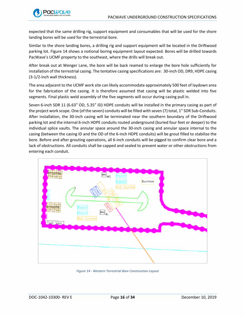
Similar to the shore landing bores, a drilling rig and support equipment will be located in the Driftwood
parking lot. Figure 14 shows a notional boring equipment layout expected. Bores will be drilled towards
PacWave’s UCMF property to the southeast, where the drills will break out.
After break out at Wenger Lane, the bore will be back reamed to enlarge the bore hole sufficiently for
installation of the terrestrial casing. The tentative casing specifications are: 30-inch OD, DR9, HDPE casing
(3-1/2-inch wall thickness).
The area adjacent to the UCMF work site can likely accommodate approximately 500 feet of laydown area
for the fabrication of the casing. It is therefore assumed that casing will be plastic welded into five
segments. Final plastic weld assembly of the five segments will occur during casing pull in.
Seven 6-inch SDR 11 (6.63” OD, 5.35” ID) HDPE conduits will be installed in the primary casing as part of
the project work scope. One (of the seven) conduits will be filled with seven (7) total, 1” SDR Sub-Conduits.
After installation, the 30-inch casing will be terminated near the southern boundary of the Driftwood
parking lot and the internal 6-inch HDPE conduits routed underground (buried four feet or deeper) to the
individual splice vaults. The annular space around the 30-inch casing and annular space internal to the
casing (between the casing ID and the OD of the 6-inch HDPE conduits) will be grout filled to stabilize the
bore. Before and after grouting operations, all 6-inch conduits will be pigged to confirm clear bore and a
lack of obstructions. All conduits shall be capped and sealed to prevent water or other obstructions from
entering each conduit.
Figure 14 - Western Terrestrial Bore Construction Layout

PACWAVE UNDERGROUND CONSTRUCTION SPECIFICATIONS
DOC-1042-10300- REV E Page 17 of 34 December 10, 2019
4.1 Terrestrial Back Haul Construction Impediments
Multiple limitations to underground construction exist between Driftwood and the UCMF, including:
Private properties (see Figure 15)
o Residential and vacant
Highway 101 crossing
Wetlands
o Covering the southern 2/3 of the Driftwood property
o Wetlands at various points along Highway 101
o Wetlands on the UCMF property
Existing utilities along Highway 101 right-of-way
o Overhead power/cable on west side of 101
o Underground water main on west side of 101
o Underground telephone on east side of 101
o Multiple underground laterals crossing 101
Water
Telephone
Power
CATV
Limited HDPE casing lay out area at Wenger Lane property (see Figure 16)
Figure 15- Terrestrial Route Property Ownership

PACWAVE UNDERGROUND CONSTRUCTION SPECIFICATIONS
DOC-1042-10300- REV E Page 18 of 34 December 10, 2019
Figure 16 – Potential Casing Laydown Area
4.2 Terrestrial Back Haul Casing Assembly
Figures 17 and 18 below show the preliminary casing assembly planned. The primary requirement is
installation of seven total, 6-inch HDPE conduits (per ASTM F2160 or equivalent) along the bore route.
Final diameter of the large casing and wall thickness of all casings and conduits are open to modification
by the contractor based on design optimization for installation. Installation of the electrical and fiber optic
cables shown are not included within this scope of work.
Figure 10 - Terrestrial Back Haul Casing Bill of Materials

PACWAVE UNDERGROUND CONSTRUCTION SPECIFICATIONS
DOC-1042-10300- REV E Page 19 of 34 December 10, 2019
Figure 11 – Terrestrial Casing Assembly
4.3 Terrestrial Back Haul Bore Plan
Construction will consist of boring a single drill path from the parking lot of Driftwood S, towards the
southeast with drill break out at approximately 2,250 feet at the UCMF property. On completion of the
bore path drilling, the bore will be enlarged through back reaming and an HDPE casing and conduit
package installed via back haul from the Wenger Lane property towards Driftwood.
Figure 19 shows a potential vertical profile view of the planned bore path with Driftwood shown on the
left and Wenger Lane on the right. The bore plan involves drilling relatively deep to install the system in
soft, but competent rock. Rock formations are expected to be found at 20 to 40 feet below Highway 101.
Geotechnical core drilling at Driftwood (in the parking lot) found siltstone starting at 60 feet below grade
with limited change in property going deeper (covered in detail in the appendix). The preferred drill plan
will route through soft rock with up to 180 feet of cover when passing below the wetlands located on the
southern area of the Driftwood property. The rock formations expected should provide stable geology for
boring operations and good bore path steering while also being drillable.

PACWAVE UNDERGROUND CONSTRUCTION SPECIFICATIONS
DOC-1042-10300- REV E Page 20 of 34 December 10, 2019
Potential for impact or damage to local wetlands, Highway 101 and existing utilities will be minimized by
the planned drilling depth and formation. Permitting agencies are particularly concerned with the
potential for inadvertent release of drilling fluid (or frac-out) into the local wetlands. Bore design is critical
to minimizing this possibility and the chosen contractor will be responsible for providing an HDD
Contingency Plan for the project. The deep drill plan shown is one possible mitigation measure, providing
a stable bore wall and geologic impediments to drill fluid migration. Final bore path is open to
consideration of all factors, towards the goal of maximum project safety and minimum potential for
inadvertent fluid break out events.
Figure 12 - Terrestrial Back Haul Bore Path, Profile View

PACWAVE UNDERGROUND CONSTRUCTION SPECIFICATIONS
DOC-1042-10300- REV E Page 21 of 34 December 10, 2019
Figure 20 shows the plan, or horizontal view of the bore profile. A large, horizontal radius is shown over
the southern section, where vertical steering calls for a constant 16 degree up slope.
Figure 13 - Terrestrial Back Haul Plan View
PACWAVE UNDERGROUND CONSTRUCTION SPECIFICATIONS
DOC-1042-10300- REV E Page 22 of 34 December 10, 2019
5 Grid Interconnect
In addition to the shore landing and terrestrial back haul bores, an underground conduit is to be installed
on the Wenger Lane property to Highway 101 with overhead lines used for crossing Highway 101. This
installation is not part of this scope of work.
PACWAVE UNDERGROUND CONSTRUCTION SPECIFICATIONS
DOC-1042-10300- REV E Page 23 of 34 December 10, 2019
6 Boring and Conduit Site Work Completion
On completion of all boring and casing/conduit installation, the drilling rig and associated equipment will
be demobilized from the site and the final phase of underground site work completed. Excavation of
Driftwood parking lot will be performed as required using back hoe and other digging equipment to prep
the site for installation of splice vaults. The concrete vaults will be set below grade and mechanically
terminated and tied into the shore landing conduits.
Further excavation (within the Driftwood parking lot boundary) will be performed between the splice
vaults and the termination of the bored casing. The terrestrial conduits and copper grounding wires will
be extended, laid four or more feet below grade and mechanically terminated to the splice vaults. A final
sizing pig pull will be performed for each conduit to insure a clear bore prior to completion of conduit
installation and acceptance.
The site will then be back filled, leveled and compacted according to construction plans, bringing
underground construction work (Phase 1) to a conclusion. Final site work will involve prep and completion
of paving, replacement of curbs and all landscaping by contractors other than the boring contractor and
is therefore not part of this scope of work.
6.1 Driftwood Underground Splice Vaults
The subsea cables from the offshore PacWave test site will land at Driftwood. The underground splice
vaults (or BMHs) will provide termination points for each of the subsea cables and a splice point to
transition to terrestrial power cables that will extend the power cabling to the UCMF. Power from offshore
test site wave energy converters will interconnect with the local utility grid through the UCMF. Five subsea
cables will be landed and terminated in five splice vaults at the Driftwood location (one subsea cable per
vault). All hardware for this project at Driftwood will reside below grade, within the confines of the parking
lot area.
Each subsea cable will be electrically and mechanically terminated within a cable vault (by other project
contractors) located underneath the parking lot area at Driftwood. The cable vaults shall include:
1. Mechanical termination of the offshore underground conduit.
a. Sufficient to withstand the breaking load of the steel conduit installed.
2. Mechanical termination of the subsea cable at the entry point into the splice vault.
a. Sufficient to withstand the breaking load of the cable, estimated at 100,000 lbs.
3. Mechanical termination of terrestrial back haul, 6-inch HDPE conduits.
a. Sufficient to withstand breaking load of HDPE conduits.
4. Mechanical termination of terrestrial back haul cables at the entry point into the splice vault.
a. Sufficient to withstand the breaking load of each cable, estimated at 5,000 lbs per
conductor.
5. Slack cable storage organized in a manner to permit easy access for maintenance of any one
power cable without disturbing other cables.
6. The splice vault shall provide sufficient cable slack storage to permit cable splices to be worked
on in a splice truck or tent located near and above the splice vault opening.

PACWAVE UNDERGROUND CONSTRUCTION SPECIFICATIONS
DOC-1042-10300- REV E Page 24 of 34 December 10, 2019
7. Safe and secure storage of the waterproof cable splices that interconnect each subsea cable to
equivalent terrestrial power and fiber optic cabling.
8. Ground system to provide a low impedance earth ground connection for personnel and
equipment safety.
a. Supplied by other project electrical contractors
b. Portions may be installed during the same timeframe as underground construction
c. Preliminary grounding details are provided in the appendix.
9. Splice vault design and location shall not prevent regular vehicle traffic from safely driving,
parking, etc. within the parking lot at Driftwood.
6.1.1 Splice Vault Design & Construction
Each subsea cable landed at Driftwood will be terminated and secured in a 10-foot cubed (10’ x 10’ x 10’)
splice vault that allows easy access to individual subsea cables without interfering with the safe operation
of the other cables. Vaults will further interconnect with individual 6-inch HDPE conduits routing through
the terrestrial back haul bore casing.
Two 6-inch HDPE conduits will be installed to provide interconnections between adjacent splice vaults.
The middle vault (BMH #3) shall terminate three, 6-inch HDPE conduits routing from the terrestrial back
haul bore casing. One casing will be utilized for power cabling, one casing will serve to receive fiber optic
cables from the UCMF with further distribution to other vaults via the interconnect conduits. The third
HDPE conduit terminating in BMH #3 will serve as a project spare. This conduit will be capped and sealed
for future use.
Access to the splice vaults will be via manhole covers located in the parking lot pavement. The splice vaults
will be engineered to meet all structural requirements sufficient to permit regular traffic to move about
the Driftwood parking lot. NOTE: Driftwood is designated as an Oregon Department of Transportation
(ODOT) rest area serving Highway 101, therefore the parking lot and all underground structures must
meet (at a minimum) the roadway requirements as defined by ODOT (AASHTO HL93 load specifications).
Features to support storage of spare cable length and cable splice equipment will be included in the splice
vault design. An engineered vault design showing cable deployment for splicing and storage shall be
provided prior to fabrication of any splice vault components.
6.1.2 Splice Vault Ground system
An earth ground system for the splice vaults will be engineered and established by other project
contractors to safely ground all non-conductor metallic components of the cable landing system. The
splice vaults will be engineered to connect all vault metallic components to this ground system. The
ground system design will be sufficient to safely ground all components in the event of a cable fault or
similar event that energizes components.
Grounding system features will be approved by OSU prior to installation. As built configuration of the
ground system shall also be documented in a stamped report. Preliminary grounding details are provided
in Appendix 10.1.5 for reference.

PACWAVE UNDERGROUND CONSTRUCTION SPECIFICATIONS
DOC-1042-10300- REV E Page 25 of 34 December 10, 2019
6.1.3 Splice Vault Installation
The vendor shall provide an engineered design for installation of the splice vaults. The plan shall identify
site preparation requirement prior to splice vault installation, equipment and personnel required for
installation, installation procedure, and site work required after installation of the vaults.
6.1.4 Interface of Splice Vaults with Shore Landing HDD Casings
Each subsea cable will enter an individual splice vault via the previously installed steel shore landing
conduits. An engineered design detailing the steel conduit and termination to the splice vault shall be
provided prior to the start of work on this project. Design details shall include mechanical and electrical
termination of the steel conduit, and mechanical termination of the terrestrial HDPE conduits.
6.1.5 Mechanical Termination of Subsea Cable in the Splice Vaults
A mechanical termination assembly shall be included at the entry point for each subsea cable. The
mechanical termination shall transfer tension loads from the cable into the structure of the vault. The
subsea cable shall have its armor wires or other tensile load element(s) mechanically terminated in the
splice vault to mitigate any mechanical tension loads transmitted through the cable from offshore. The
details of the cable termination assembly will be provided by the cable manufacturer during detailed
design of the cable. The underground contractor shall provide an engineered design to attach the cable
vendor supplied, mechanical termination assembly as a deliverable prior to fabrication of the termination
hardware. As built documentation of the termination assembly shall be provided as a deliverable. Details
of the design requirements will be provided during detailed system design. Strength of the termination
and anchoring system is expected to require approximately 100,000 lbs tensile load capacity.
6.1.6 Interface of Splice Vault with Terrestrial Conduits
As described previously, the terrestrial conduit system will consist of a 30-inch HDPE casing, filled with
seven, 6-inch, SDR 11 HDPE conduits, one of which will contain seven smaller sub-conduits for fiber optic
cable routing. On completion of terrestrial casing pull in, the 30-inch casing will be terminated near the
southern boundary of the Driftwood parking lot and the seven internal 6-inch conduits routed four or
more feet below grade to the five individual splice vaults. Figure 21 shows the general configuration.
Figure 21 - Terrestrial Conduit Interface to BMHs

PACWAVE UNDERGROUND CONSTRUCTION SPECIFICATIONS
DOC-1042-10300- REV E Page 26 of 34 December 10, 2019
As Shown, one conduit routes to each of BMH #s 1, 2, 4 and 5. Three conduits will be routed to and
terminate at BMH #3. One of these conduits will be for fiber cable routing and will feature seven internal
1-inch HDPE sub-conduits for this purpose. The two additional conduits will serve for power cable routing
plus a spare, empty conduit. Two 6-inch SDR 11, HDPE conduits will be installed as cross overs between
adjacent vaults for the purpose of distributing fiber and any future need to cross over cable systems.
6.1.7 Cable Vault Access
Access to the cable vault shall be via a manhole, sufficiently large enough to accommodate 20-inch bend
radius cables (40-inch bending diameter).
6.2 UCMF Underground Cable Vault
All power and fiber cables routing from Driftwood to the UCMF will terminate in an underground cable
vault on the west side of the UCMF on Wenger Lane. The actual cable vault system will be designed and
constructed by other project contractors after completion of underground casing. Mechanical and
electrical termination of the casing, conduits and cable at this vault will be performed by other project
contractors once the vault and other building systems are constructed.
6.2.1 UCMF Cable Vault Ground System
An earth ground system for the UCMF cable vault will be engineered and established by other project
contractors to safely ground all non-conductor metallic components of the cable system.
When installed in the future, the actual power and fiber optic cables will route through the underground
cable vault, through cable ways installed in the UCMF building (future construction) and ultimately
terminate at medium voltage switchgear and fiber termination points internal to the facility.

PACWAVE UNDERGROUND CONSTRUCTION SPECIFICATIONS
DOC-1042-10300- REV E Page 27 of 34 December 10, 2019
Figure 22 shows a general configuration of the underground cable vault. Further details are included in
Appendix 10.1.6.
Figure 14 - UCMF Cable Vault Plan View

PACWAVE UNDERGROUND CONSTRUCTION SPECIFICATIONS
DOC-1042-10300- REV E Page 28 of 34 December 10, 2019
7 Local Geology
Significant survey work in the area has been performed to date, including seismic surveys of most of the
route, plus a recent core drilling. The results of these surveys generally fit the typical geology of the area
and form the basis for the present assumptions of geology for all drilling routes. Detailed reports of seismic
and geotechnical coring investigations to date are included in the attached appendices.
7.1 Driftwood Survey Findings
Notional findings of the Driftwood seismic survey include:
Alsea Formation at ~ 0 ft elevation (vs. sea level) and deeper.
o Mudstone/siltstone
o Strength TBD
Terrace deposits from ~ 0 to 20 ft elevation
o Compacted sands, shells and organic materials
Loose beach sand ~20 to 50 ft elevation
An example of the seismic survey results is shown in Figure 23 below.
Figure 15 - Seismic Survey Example

PACWAVE UNDERGROUND CONSTRUCTION SPECIFICATIONS
DOC-1042-10300- REV E Page 29 of 34 December 10, 2019
7.2 Terrestrial Back Haul Route Geology
Based on seismic surveys of sections of the terrestrial back haul route, a generalized interpretation of the
expected geology along the back haul route is shown in Figure 24. The blue zone represents relatively
unconsolidated, sand and compacted sand/shell deposits. The green zone is shown as a possible transition
zone consisting of mudstone and sandstone. Red highlights higher strength mudstone, siltstone or
sandstone deposits, which are expected to be stable and drillable.
Figure 16 - Generalized Geology Along Back Haul Route
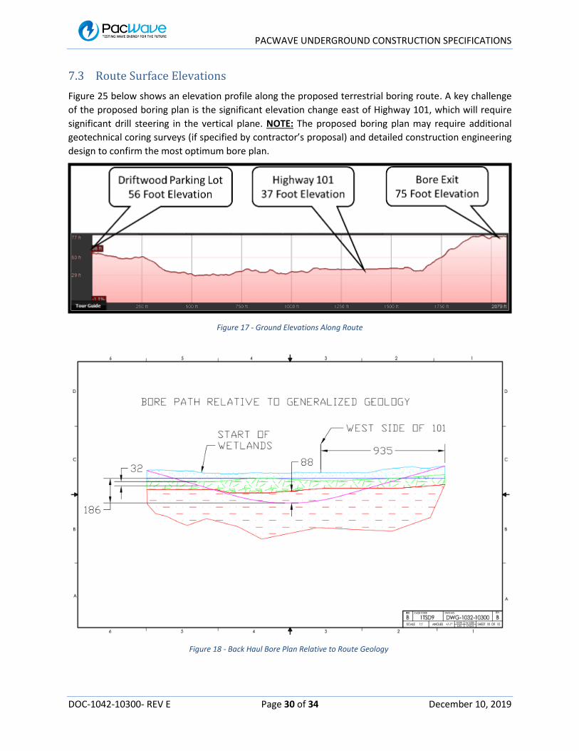
PACWAVE UNDERGROUND CONSTRUCTION SPECIFICATIONS
DOC-1042-10300- REV E Page 30 of 34 December 10, 2019
7.3 Route Surface Elevations
Figure 25 below shows an elevation profile along the proposed terrestrial boring route. A key challenge
of the proposed boring plan is the significant elevation change east of Highway 101, which will require
significant drill steering in the vertical plane. NOTE: The proposed boring plan may require additional
geotechnical coring surveys (if specified by contractor’s proposal) and detailed construction engineering
design to confirm the most optimum bore plan.
Figure 17 - Ground Elevations Along Route
Figure 18 - Back Haul Bore Plan Relative to Route Geology

PACWAVE UNDERGROUND CONSTRUCTION SPECIFICATIONS
DOC-1042-10300- REV E Page 31 of 34 December 10, 2019
8 Geotechnical Coring Investigation
Appendix 10.3 contains data and reports resulting from initial geotechnical core drill investigations
performed to date at the Driftwood shore landing site. The initial core drilling effort has consisted of a
single, vertical core bore along the southern edge of the Driftwood parking lot. The purpose of this effort
is to provide ground truth data to coorelate against the seismic survey work completed previously. The
results of this investigation provide good insight into the expected geology along the boring routes.
NOTE: Results from the Driftwood geotechnical investigation will be available to potential proposers by
the end of December 2019. A draft core log can be found in the Appendices.
All responding bidders are encouraged to consider if additional geotechnical investigations along the
terrestrial boring route are warranted prior to completion of a bore plan. Responding bidders should
include proposed costs associated with any further geotechnical investigations that will be required for
project engineering as part of their proposal.
NOTE: There are a number of factors limiting access along the complete terrestrial route, which makes
completing geotechnical coring a challenge. Specifically, the wetlands area between the Driftwood
parking lot and Highway 101 is not accessible to any type of mechaninized drill rig and private property
easements along the route do not specify access for such investigations. Locations available for further
investigations, beyond the Wenger Lane property are limited to the Driftwood parking lot, the Highway
101 right-of-way and the UCMF property on Wenger Lane.
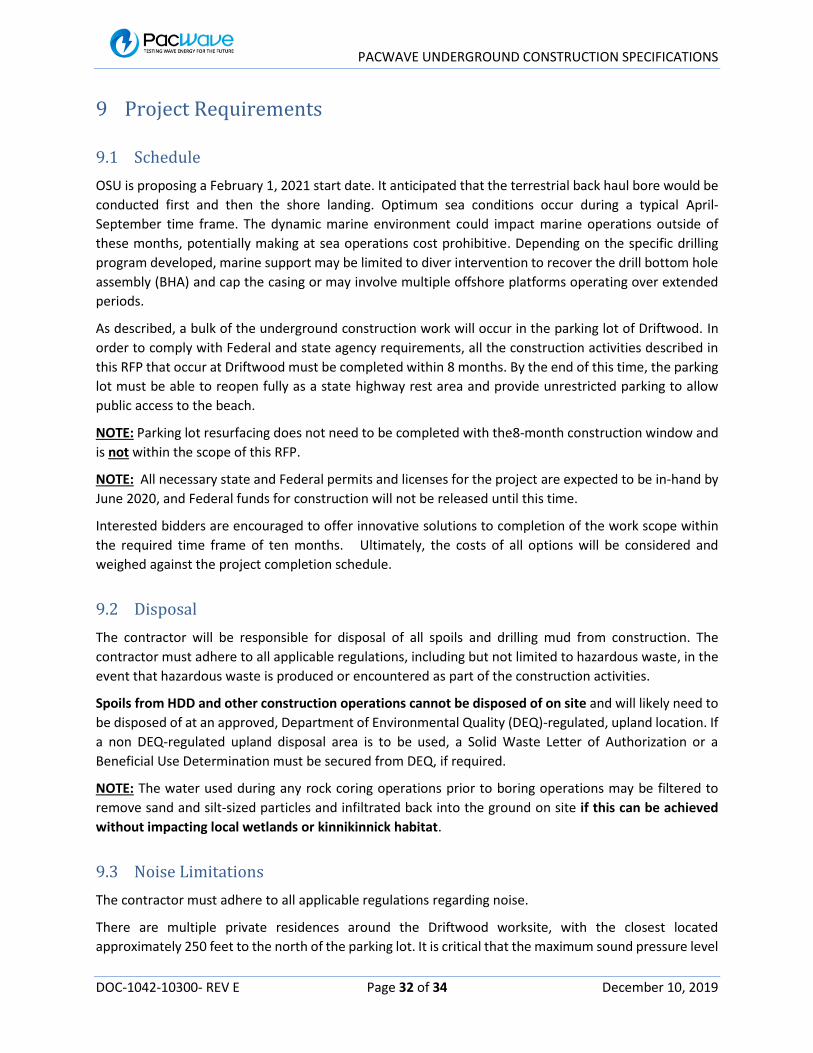
PACWAVE UNDERGROUND CONSTRUCTION SPECIFICATIONS
DOC-1042-10300- REV E Page 32 of 34 December 10, 2019
9 Project Requirements
9.1 Schedule
OSU is proposing a February 1, 2021 start date. It anticipated that the terrestrial back haul bore would be
conducted first and then the shore landing. Optimum sea conditions occur during a typical April-
September time frame. The dynamic marine environment could impact marine operations outside of
these months, potentially making at sea operations cost prohibitive. Depending on the specific drilling
program developed, marine support may be limited to diver intervention to recover the drill bottom hole
assembly (BHA) and cap the casing or may involve multiple offshore platforms operating over extended
periods.
As described, a bulk of the underground construction work will occur in the parking lot of Driftwood. In
order to comply with Federal and state agency requirements, all the construction activities described in
this RFP that occur at Driftwood must be completed within 8 months. By the end of this time, the parking
lot must be able to reopen fully as a state highway rest area and provide unrestricted parking to allow
public access to the beach.
NOTE: Parking lot resurfacing does not need to be completed with the8-month construction window and
is not within the scope of this RFP.
NOTE: All necessary state and Federal permits and licenses for the project are expected to be in-hand by
June 2020, and Federal funds for construction will not be released until this time.
Interested bidders are encouraged to offer innovative solutions to completion of the work scope within
the required time frame of ten months. Ultimately, the costs of all options will be considered and
weighed against the project completion schedule.
9.2 Disposal
The contractor will be responsible for disposal of all spoils and drilling mud from construction. The
contractor must adhere to all applicable regulations, including but not limited to hazardous waste, in the
event that hazardous waste is produced or encountered as part of the construction activities.
Spoils from HDD and other construction operations cannot be disposed of on site and will likely need to
be disposed of at an approved, Department of Environmental Quality (DEQ)-regulated, upland location. If
a non DEQ-regulated upland disposal area is to be used, a Solid Waste Letter of Authorization or a
Beneficial Use Determination must be secured from DEQ, if required.
NOTE: The water used during any rock coring operations prior to boring operations may be filtered to
remove sand and silt-sized particles and infiltrated back into the ground on site if this can be achieved
without impacting local wetlands or kinnikinnick habitat.
9.3 Noise Limitations
The contractor must adhere to all applicable regulations regarding noise.
There are multiple private residences around the Driftwood worksite, with the closest located
approximately 250 feet to the north of the parking lot. It is critical that the maximum sound pressure level

PACWAVE UNDERGROUND CONSTRUCTION SPECIFICATIONS
DOC-1042-10300- REV E Page 33 of 34 December 10, 2019
of the construction work should not impact nearby residences. Experience has shown that equipment
generating 90 dBA at 10 feet did not cause disturbance at the nearest residences. If excessive noise will
be required to complete the construction work, sound screening/barriers will be required to limit the
impact. If excessive noise will be required to complete the construction work, sound screening/barriers
will be required to limit the impact. Construction operations are limited to daylight hours. Weekend
construction activity is allowable.
9.4 Restoration plan
Driftwood is home to the extremely rare Seaside Hoary Elfin butterfly, which is closely associated with the
kinnikinnick (or Bearberry) host plant. Therefore, all construction work within the state park boundary,
must occur within the footprint of the existing parking lot. Any construction outside the parking lot
footprint must employ underground construction methods (i.e. drilling or boring from within the parking
lot footprint). Therefore, no revegetation is expected outside the parking lot boundaries.
NOTE: Impacts to kinnikinnick must be avoided.
Site restoration is not within the scope of this RFP. On completion of construction activities, the contractor
shall complete all back fill and compaction, remove all equipment and rubbish. Site restoration and
parking lot paving work will be performed by other project contractors.

PACWAVE UNDERGROUND CONSTRUCTION SPECIFICATIONS
DOC-1042-10300- REV E Page 34 of 34 December 10, 2019
10 Appendices
10.1 Construction Plans
DWG-1032-10300, PACWAVE DRIFTWOOD CONSTRUCTION SITE PLAN - REV B
DWG-1058-10300, TERRESTRIAL DRILLING CASING ASSEMBLY - REV O
DWG-1059-10300, SHORELANDING SINGLE CABLE CASING ASSEMBLY - REV A
DWG-1060-10300, SHORELANDING MULTI CABLE CASING ASSEMBLY - REV O
Proposed Earth Grounding System - Driftwood Grounding 20191015 – TriAxis
Cable & Conduit Termination Vault – UCMF Terrestrial Vault 20191015 - TriAxis
10.2 Seismic Survey
REF-1039-10300, DRIFTWOOD PARKING LOT SEISMIC SURVEY REPORT - REV O
REF-1040-10300, HDD SEISMIC SURVEY REPORT - REV O
REF-1043-10300, PACWAVE TERRESTRIAL CABLE ROUTE SEISMIC SURVEY REPORT - REV O
10.3 Geotechnical Core Drilling Survey
Core Drilling Logs
Core Drilling Report – Expected to be available by early January 2020
10.4 Project Schedule
DOC-1061-10300, PACWAVE UNDERGROUND CONSTRUCTION SCHEDULE, REV O
DOC-1062-10300, PACWAVE ALT UNDERGROUND CONSTRUCTION SCHEDULE, REV O

RFP Response due 3/11/2020 at 2:00 pm, Pacific Time Page 24 of 27
Attachment B References
Use this form to provide as references current contact information for three past Projects of a similar or greater size and complexity to this Scope and that are using the equipment, methods and approach proposed and in accordance with the Scope of this RFP. Verify that the individuals identified had direct contact with the referenced project. Do not include references from any firms or individuals included in your team for this Project or any references of OSU personnel. REFERENCE 1
COMPANY: CONTACT NAME:
ADDRESS: PHONE NUMBER:
CITY, STATE ZIP: FAX NUMBER:
WEBSITE: E-MAIL:
GOODS OR SERVICES PROVIDED:
REFERENCE 2
COMPANY: CONTACT NAME:
ADDRESS: PHONE NUMBER:
CITY, STATE ZIP: FAX NUMBER:
WEBSITE: E-MAIL:
GOODS OR SERVICES PROVIDED:
REFERENCE 3
COMPANY: CONTACT NAME:
ADDRESS: PHONE NUMBER:
CITY, STATE ZIP: FAX NUMBER:
WEBSITE: E-MAIL:
GOODS OR SERVICES PROVIDED:

RFP Response due 3/11/2020 at 2:00 pm, Pacific Time Page 25 of 27
Attachment C Cost Proposal

RFP Response due 3/11/2020 at 2:00 pm, Pacific Time Page 26 of 27
Attachment D
OSU – Sample Contract

RFP Response due 3/11/2020 at 2:00 pm, Pacific Time Page 27 of 27
Attachment E OSU Performance Bond, Payment Bond

{00522815;2} Revised August 2016
OREGON STATE UNIVERSITY
PERFORMANCE BOND
Bond No._______________________________ Solicitation _____________________________ Project Name ___________________________ __________________(Surety #1) Bond Amount No. 1: $______________ __________________(Surety #2)* Bond Amount No. 2:* $______________ * If using multiple sureties Total Penal Sum of Bond: $______________ We, ________________________________________________as Principal, and the above identified Surety(ies), authorized to transact surety business in Oregon, as Surety, hereby jointly and severally bind ourselves, our respective heirs, executors, administrators, successors and assigns firmly by these presents to pay unto Oregon State University (OSU), the sum of (Total Penal Sum of Bond) _____________________________ (Provided, that we the Sureties bind ourselves in such sum “jointly and severally” as well as “severally” only for the purpose of allowing a joint action or actions against any or all of us, and for all other purposes each Surety binds itself, jointly and severally with the Principal, for the payment of such sum only as is set forth opposite the name of such Surety), and WHEREAS, the Principal has entered into contract No. ____________with the OSU, the plans, specifications, terms and conditions of which are contained within the Contract resulting from the above-referenced Solicitation; WHEREAS, the terms and conditions of the Contract, together with applicable plans, standard specifications, special provisions, schedule of performance, and schedule of Contract prices, are made a part of this Performance Bond by reference, whether or not attached to the contract (all hereafter called “Contract”); and WHEREAS, the Principal has agreed to perform the Contract in accordance with the terms, conditions, requirements, plans and specifications, and all authorized modifications of the Contract which increase the amount of the work, the amount of the Contract, or constitute an authorized extension of the time for performance, notice of any such modifications hereby being waived by the Surety: NOW, THEREFORE, THE CONDITION OF THIS BOND IS SUCH that if the Principal herein shall (1) faithfully and truly observe and comply with the terms, conditions and provisions of the Contract, in all respects, (2) shall well and truly and fully do and perform all matters and things undertaken by Contractor to be performed under the Contract, upon the terms set forth therein, and within the time prescribed therein, or as extended as provided in the Contract, with or without notice to the Sureties, (3) shall save, defend, indemnify and hold harmless OSU and its officers, board members, employees, agents and other representatives, against any direct or indirect damages or claim of every kind and description that shall be suffered or claimed to be suffered in connection with or arising out of the performance of the Contract by

{00522815;2} Revised August 2016
the Principal or its subcontractors, and (4) shall in all respects perform said contract according to law, then this obligation is to be void; otherwise, it shall remain in full force and effect. Nonpayment of the bond premium will not invalidate this bond, nor shall OSU be obligated for the payment of any premiums. This bond is given and received under authority of ORS Chapters 279C and 352, the provisions of which hereby are incorporated into this bond and made a part hereof. IN WITNESS WHEREOF, WE HAVE CAUSED THIS INSTRUMENT TO BE EXECUTED AND SEALED BY OUR DULY AUTHORIZED LEGAL REPRESENTATIVES. Dated this __________________ day of ___________________, 20__. PRINCIPAL: __________________________ By____________________________________ Signature ______________________________________ Official Capacity Attest: ________________________________ Corporation Secretary SURETY: _____________________________ [Add signatures for each surety if using multiple bonds] BY ATTORNEY-IN-FACT: [Power-of-Attorney must accompany each surety bond] ______________________________________ Name ______________________________________ Signature ______________________________________ Address ______________________________________ City State Zip _________________ ____________________ Phone Fax

{00522815;2} Revised August 2016
OREGON STATE UNIVERSITY
PAYMENT BOND
Bond No. __________________________________ Solicitation _________________________________ Project Name _______________________________ __________________(Surety #1) Bond Amount No. 1: $ ___________ __________________(Surety #2)* Bond Amount No. 2:* $ ___________ * If using multiple sureties Total Penal Sum of Bond: $ ___________ We, ________________________________________________, as Principal, and the above identified Surety(ies), authorized to transact surety business in Oregon, as Surety, hereby jointly and severally bind ourselves, our respective heirs, executors, administrators, successors and assigns firmly by these presents to pay unto Oregon State University (OSU) the sum of (Total Penal Sum of Bond) _____________________________ ______________________________ (Provided, that we the Sureties bind ourselves in such sum “jointly and severally” as well as “severally” only for the purpose of allowing a joint action or actions against any or all of us, and for all other purposes each Surety binds itself, jointly and severally with the Principal, for the payment of such sum only as is set forth opposite the name of such Surety), and WHEREAS, the Principal has entered into contract No. ___________ with OSU, the plans, specifications, terms and conditions of which are contained within the Contract resulting from the above-referenced Solicitation; WHEREAS, the terms and conditions of the contract, together with applicable plans, standard specifications, special provisions, schedule of performance, and schedule of contract prices, are made a part of this Payment Bond by reference, whether or not attached to the contract (all hereafter called “Contract”); and WHEREAS, the Principal has agreed to perform the Contract in accordance with the terms, conditions, requirements, plans and specifications, and schedule of contract prices which are set forth in the Contract and any attachments, and all authorized modifications of the Contract which increase the amount of the work, or the cost of the Contract, or constitute authorized extensions of time for performance of the Contract, notice of any such modifications hereby being waived by the Surety: NOW, THEREFORE, THE CONDITION OF THIS BOND IS SUCH that if the Principal shall (1) faithfully and truly observe and comply with the terms, conditions and provisions of the Contract, in all respects, (2) shall well and truly and fully do and perform all matters and things by it undertaken to be performed under said Contract and any duly authorized modifications that are made, upon the terms set forth therein, and within the time prescribed therein, or as extended therein as provided in the Contract, with or without notice to the Sureties, (3) shall save, defend, indemnify and hold harmless OSU, and its officers, board members, employees, agents and other representatives, against any claim for direct or indirect damages of every kind and description that shall be suffered or claimed to be suffered in connection with or arising out of the performance of the Contract by the Contractor or its subcontractors, (4) shall promptly pay all persons supplying labor, materials or both to the Principal or its subcontractors for prosecution of the work provided in the Contract; (5) shall promptly pay all contributions due the State Industrial Accident Fund and the State Unemployment Compensation Fund from the Principal or its
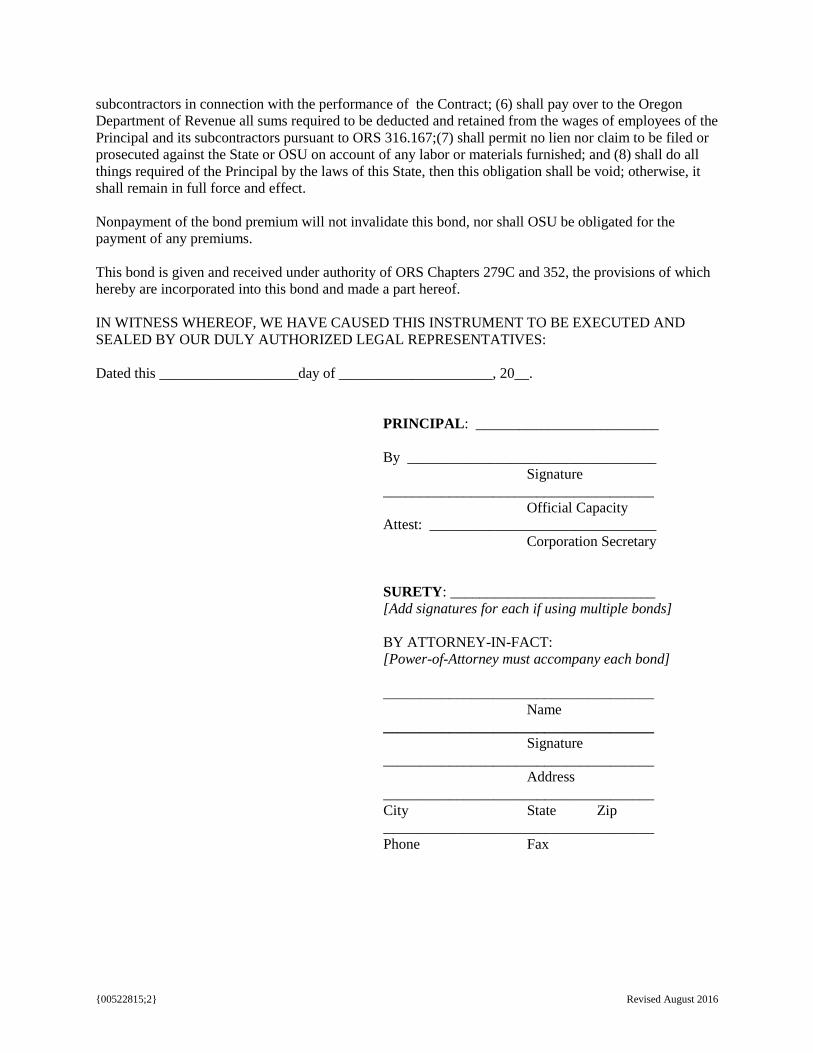
{00522815;2} Revised August 2016
subcontractors in connection with the performance of the Contract; (6) shall pay over to the Oregon Department of Revenue all sums required to be deducted and retained from the wages of employees of the Principal and its subcontractors pursuant to ORS 316.167;(7) shall permit no lien nor claim to be filed or prosecuted against the State or OSU on account of any labor or materials furnished; and (8) shall do all things required of the Principal by the laws of this State, then this obligation shall be void; otherwise, it shall remain in full force and effect. Nonpayment of the bond premium will not invalidate this bond, nor shall OSU be obligated for the payment of any premiums. This bond is given and received under authority of ORS Chapters 279C and 352, the provisions of which hereby are incorporated into this bond and made a part hereof. IN WITNESS WHEREOF, WE HAVE CAUSED THIS INSTRUMENT TO BE EXECUTED AND SEALED BY OUR DULY AUTHORIZED LEGAL REPRESENTATIVES: Dated this ___________________day of _____________________, 20__. PRINCIPAL: _________________________ By __________________________________ Signature _____________________________________ Official Capacity Attest: _______________________________ Corporation Secretary SURETY: ____________________________ [Add signatures for each if using multiple bonds] BY ATTORNEY-IN-FACT: [Power-of-Attorney must accompany each bond] _____________________________________ Name _____________________________________ Signature _____________________________________ Address _____________________________________ City State Zip _____________________________________ Phone Fax