request for proposals for hardy falls bridges design … · invites proposals for the design and...
TRANSCRIPT

Page 1 of 30
REQUEST FOR PROPOSALS
FOR
HARDY FALLS BRIDGES DESIGN-BUILD
RFP #: R18-422 ISSUED ON: JULY 16, 2018 CLOSING DATE AND TIME: AUGUST 7, 2018 at 3:00pm Local Time

RFP# R18-422 Hardy Falls Bridges Design-Build
Page 2 of 30
Summary, Contents & Instructions:
Summary: Through this Request for Proposals, the Regional District of Central Okanagan (the “Regional District”) invites Proposals for the design and build of two pedestrian bridges at Hardy Falls Regional Park, located at 6649 Hardy Street, Peachland, BC.
Substantial Performance for all work must be achieved no later than June 30th, 2019.
This RFP document sets-out: the Scope of Work required; the process for submission, evaluation and award of the Contract; the terms and conditions of the Contract; plus forms which outline the information a Respondent to this RFP should submit in their Proposal.
Contents: This Request for Proposals (the “RFP”) is organized into the following parts:
Part A: The Scope of Work – full details of the Scope of Work required Part B: The RFP Process – the process for submissions, evaluation and award of the Contract Part C: The Contract – the Contract the Regional District will enter into with the selected
Contractor Part D: Submission Forms – the forms a Respondent should submit in their Proposal
Exhibits which are referenced in, and form part of, Part A are as follows:
Exhibit A: Site Map of Hardy Falls Regional Park Bridge #2 & #8 Replacements Exhibit B: Recovery Plan for Hardy Falls Regional Park (1 page) Exhibit C: Structural Assessment Report Hardy Falls (37 pages) Exhibit D: Regional Parks Design Guidelines for Bridges (10 pages)
Instructions: Whenever you see the following symbol and box throughout this document, this box is providing instructions to a Respondent on what this section means and/or what a Respondent must do:
Example:
Whenever you see this box throughout the RFP document, the text is providing instructions or information on what this section means and/or what a Respondent must do.
RFP# R18-422 Hardy Falls Bridges Design-Build
Page 3 of 30
Part A: The Scope of Work (Owner’s Statement of Requirements)
This Part A provides details on the Design Services and Work required by the Regional District (which are collectively referred to as the “Owner’s Statement of Requirements”). Respondents should ensure they are fully capable of providing all of the requirements outlined, as this section will form the Owner’s Statement of Requirements in the final Contract.
1. Background: In 2017, the Central Okanagan region was significantly impacted by stream and lake flooding. The Regional District of Central Okanagan Parks Services department experienced damage within some of its Regional Parks. In particular, Hardy Falls Regional Park was impacted severely by high water flows, and as a result two of the existing pedestrian bridges were compromised. These two bridges (#2 and #8) now require replacement.
2. Scope of Work & Requirements: The Regional District requires a Contractor to design and build two clear-span pedestrian bridges at the locations in the park detailed in Exhibit A. Detailed requirements for the Design Services and the Work are as follows:
2.1. Bridge #2 Replacement: 2.1.1. Detailed Design & Engineering: The Contractor shall complete structural engineered
and stamped design drawings for the new bridge to meet the following requirements:
2.1.1.1. Must meet a load rating of 2,950KG (based on pedestrian traffic and rubber-tired maintenance equipment).
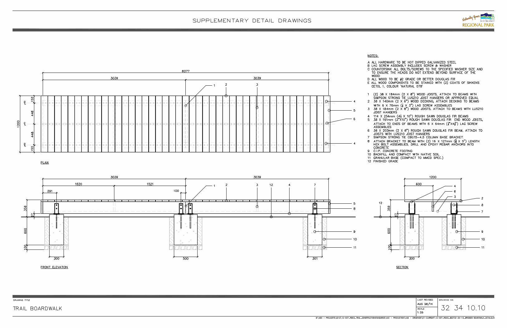
2.1.1.2. Has a minimum 25-year lifespan (50 years on superstructure). Preference is for Douglas Fir Timber girders with wooden deck to meet DFA requirements.
2.1.1.3. Clear-span bridge on new abutments. 2.1.1.4. Bridge #2 has an estimated length of 13.66m. 2.1.1.5. Bridge width of 2.2m (deck width inside of curb to inside of curb). 2.1.1.6. Incorporates guardrails meeting the Regional Park Design standard for
guardrails along the sides of the new bridge. 2.1.1.7. Bridge approaches 2.1.1.8. The Contractor shall allow for Regional District reviews of the proposed design
at key junctions in the design process. 2.1.1.9. Design drawings must be stamped and sealed by an engineer licensed to
practice in the Province of British Columbia for works of a similar nature.

RFP# R18-422 Hardy Falls Bridges Design-Build
Page 4 of 30
2.1.2. Construction and Installation: The Contractor shall complete all construction and installation Work for the approved bridge design. Work shall include, but not be limited to: 2.1.2.1. Mobilization / demobilization; 2.1.2.2. Project management, and management of site access and security; 2.1.2.3. Install environmental controls as per environmental terms and conditions and
best management practices for such works in sensitive arrangements; 2.1.2.4. Clear and grub if required; 2.1.2.5. Construct and install the new bridge and components; 2.1.2.6. Construct new bridge approaches.
2.1.3. Site Clean-up and Remediation: Work to include, but not be limited to:
2.1.3.1. Remove and dispose of debris and excess materials; 2.1.3.2. Rake and grade roughened areas; and 2.1.3.3. Seed any disturbed areas with approved Regional Park native seed mix.
2.2. Bridge #8 Replacement: 2.2.1. Detailed Design & Engineering: The Contractor shall complete structural engineered
and stamped design drawings for the new bridge to meet the following requirements: 2.2.1.1. Must meet a load rating of 2,950KG (based on pedestrian traffic and rubber-
tired maintenance equipment). 2.2.1.2. Has a minimum 25-year lifespan (50 years on superstructure). Preference is
for Douglas Fir Timber girders with wooden deck to meet DFA requirements. 2.2.1.3. Clear-span bridge on new abutments. 2.2.1.4. Bridge #8 has an estimated length of 14.04m. 2.2.1.5. Bridge has a width of 2.2m (deck width inside of curb to inside of curb). 2.2.1.6. Incorporates guardrails meeting the Regional Park Design standard for
guardrails along the sides of the new bridge. 2.2.1.7. Bridge approaches 2.2.1.8. The Contractor shall allow for Regional District reviews of the proposed design
at key junctions in the design process. 2.2.1.9. Design drawings must be stamped and sealed by an engineer licensed to
practice in the Province of British Columbia for works of a similar nature.
2.2.2. Construction and Installation: The Contractor shall complete all construction and installation Work for the approved bridge design. Work shall include, but not be limited to: 2.2.2.1. Mobilization / demobilization; 2.2.2.2. Project management, and management of site access and security; 2.2.2.3. Install environmental controls as per environmental terms and conditions and
best management practices for such works in sensitive arrangements; 2.2.2.4. Clear and grub if required;

RFP# R18-422 Hardy Falls Bridges Design-Build
Page 5 of 30
2.2.2.5. Construct and install the new bridge and components; 2.2.2.6. Construct new bridge approaches.
2.2.3. Site Clean-up and Remediation: Work to include, but not be limited to:
2.2.3.1. Remove and dispose of debris and excess materials; 2.2.3.2. Rake and grade roughened areas; and 2.2.3.3. Seed any disturbed areas with approved Regional Park native seed mix.
3. Optional Extra Work: The following will be considered as Optional Extra Work and will be added to the Scope of Work outlined in section 2, at the Owner’s discretion, upon execution of the Contract:
3.1. Optional Extra Work for Bridge #2: 3.1.1. Use weathering steel girders instead of the identified Douglas Fir Timber girders.
3.2. Optional Extra Work for Bridge #8:
3.2.1. Use weathering steel girders instead of the identified Douglas Fir Timber girders.
4. Required Schedule & Milestone Dates:
Substantial Performance for all Work for both bridges, as detailed in Section 2, must be achieved before June 30th, 2019. The Regional District has a preference for the work to be completed sooner if possible.
5. Overall Objectives / Performance Standards: Given the nature of this project, the Contractor must meet the following performance standards:
• Schedule and Milestone dates met; • Regular in-person monthly meetings to provide updates; and • Regular daily and weekly communication by email or phone.
6. Contract Security (Bonding) Requirements: The Contractor shall, prior to commencement of the Work, provide the following Contract Security to the Regional District:
• A Performance Bond and a Labour and Material Payment Bond, each in the amount of 50 percent of the Contract Price, issued by a surety licensed to carry on the business of suretyship in the province of British Columbia, and in a form acceptable to the Owner. All bonds shall be in accordance with the latest edition of CCDC 221 and CCDC 222. The Performance Bond shall remain in force as a maintenance bond for the Warranty Period as defined in the Contract.

RFP# R18-422 Hardy Falls Bridges Design-Build
Page 6 of 30
7. Disclosures by the Regional District: • The execution of a Contract as a result of this RFP is subject to final funding approval of the
recovery plan by the Provincial Disaster Financial Assistance (DFA) Program. • The Regional District has already applied for a Water Sustainability Act Section 11 Application
as notification for the project. • The Regional District has detailed drone topographical survey and imagery that is considered
to be accurate enough to complete the project.

RFP# R18-422 Hardy Falls Bridges Design-Build
Page 7 of 30
Part B: The RFP Process
This Part B details the terms and conditions of how this RFP process will be run by the Regional District, and how the Contractor will be selected. Respondents to this RFP must ensure they follow all the terms detailed below. Failure to follow the terms of this Part B may result in a Proposal being rejected.
1. Key Details: 1.1. RFP Contact Person:
The sole point of contact at the Regional District of Central Okanagan for any queries or questions related to this RFP is: Andy Brennan, Purchasing Consultant [email protected]
The above-named RFP Contact Person is the only person that any Respondent to this RFP may contact during this RFP process. Information obtained from any source other than the RFP Contact Person is unofficial and must not be relied upon as part of this RFP. Respondents must not contact any other employees, officers, consultants, agents, elected officials or other representatives of the Regional District of Central Okanagan regarding matters related to this RFP. Any Respondent found to have contacted persons other than the RFP Contact Person, may be disqualified from submitting a Proposal, or have their Proposal rejected. All questions regarding this RFP must be submitted in writing prior to the Deadline for Questions detailed under Section 1.2 of this Part B. Questions received after the Deadline for Questions will be addressed if time permits. The Respondent is solely responsible for seeking any clarification required regarding this RFP, and the Regional District shall not be held responsible for any misunderstanding by the Respondent.
1.2. Timetable: This RFP process will run to the following timetable. This timetable may be amended at the Regional District’s discretion through the issuance of an addendum to this RFP.
Event: Date: Issue Date of this RFP July 16th, 2018 Site Meeting Date July 25th, 2018 at 10am Deadline for Questions July 30th, 2018 Last Day for Issue of Addenda July 31st, 2018 RFP Closing Date and Time: August 7th, 2018 3:00 PM Local Time Contract Execution Date (estimated) August 14th, 2018
1.3. Site Meeting Details: A non-mandatory site meeting will be held at the following time and place to answer any questions Respondents may have before submitting a Proposal:

RFP# R18-422 Hardy Falls Bridges Design-Build
Page 8 of 30
At the entrance to Hardy Falls Regional Park, 6649 Hardy Street, Peachland, BC at 10:00AM on Monday July 25th, 2018.
1.4. Submission of Proposals (Address, Date & Time, Format): Proposals to this RFP should be submitted in accordance with the following:
Closing Location: Proposals must be submitted at: Regional District of Central Okanagan Main Reception 1450 KLO Road, Kelowna, BC. V1W 3Z4 Attn: Andy Brennan, Purchasing Consultant
RFP Closing Date and Time: Proposals must be received no later than the Closing Date and Time detailed in section 1.2 above.
Proposal Format: One paper original, and two paper copies (3 copies total), in a sealed envelope containing all the information required in the forms listed under Part D – Submission Forms. The envelope should be clearly marked with the name and address of the Respondent, as well as the words “R18-422 Hardy Falls Bridges Design-Build RFP”.
It is the Respondent’s sole responsibility to ensure that the Proposal is received before the RFP Closing Date and Time. Proposals sent by facsimile or email will not be accepted.
2. Definitions Used in this RFP:
The following are definitions used in this RFP document. Whenever one of the following terms is used with a capitalized first letter, the term shall have the meaning as set out in this section.
2.1. “Addenda” or “Addendum” means additional information or amendments to this RFP, issued by the Regional District in accordance with Section 5 of this Part B.
2.2. “Regional District” means the Regional District of Central Okanagan 2.3. “Contract” means a written agreement for the provision of the Work that may result from this
RFP, executed between the Regional District and the successful Respondent to this RFP. 2.4. “Contractor” means the successful Respondent to this RFP who enters into a Contract with the
Regional District. 2.5. “Closing Date and Time” means the date and time that Proposals to this RFP must be received
by in accordance with Section 1.4 of this Part B. 2.6. “Proposal” means a Proposal submitted by a Respondent in response to this RFP. 2.7. “Respondent” means a person or entity that submits a Proposal to this RFP. 2.8. “RFP” means this Request For Proposals # R18-422, including all Parts A to D. 2.9. “Section” means the numbered section of the referenced part of this RFP. 2.10. “Work”, “Works”, or “Scope of Work” means the design services, construction, installation
and associated works which the Regional District seeks to be provided by the Contractor, as outlined in Part A.
2.11. “Subcontractor” means a person, partnership, firm or corporation that the Respondent proposes to contract with to deliver part of the Work, in a subordinate relationship to the Respondent.

RFP# R18-422 Hardy Falls Bridges Design-Build
Page 9 of 30
3. Amendment of a Proposal by Respondent: A Respondent may amend a Proposal at any time up until the RFP Closing Date and Time. Amendments must be submitted in the same way as the original Proposal, as detailed in Section 1.4 of this Part B. Amendments to a Proposal must be clearly labelled as such, must contain the RFP reference number and title, and the full legal name and legal address of the Respondent. Amendments must clearly detail which part(s) of the Proposal is being amended or replaced.
4. Withdrawal of a Proposal by Respondent: A Respondent may withdraw a Proposal that is already submitted at any time throughout the RFP process, including after the Closing Date and Time.
5. Addenda Issued by Regional District: This RFP may only be amended by way of an Addendum issued in accordance with this Section. At any time up until the Closing Date and Time, the Regional District may issue an Addendum in order to amend, clarify, or answer questions to this RFP. Each Addendum will be issued at the same location and in the same manner as this RFP document (at www.regionaldistrict.com/purchasing). Each Addendum will form an integral part of this RFP. Respondents are solely responsible for checking for Addenda up until the Closing Date and Time. If the Regional District deems it necessary to issue an Addendum after the Last Day for Issue of Addenda, as detailed in Section 1.2 of this Part B, then the Regional District may extend the Closing Date and Time in order to provide Respondents with more time to complete their Proposal.
Proposals should confirm receipt of all Addenda in Appendix A – Certification Form of their Proposal.
6. Evaluation of Proposals & Award of Contract: The Regional District will conduct the evaluation of Proposals and selection of a successful Respondent in accordance with the process detailed in this Section. Evaluation of Proposals will be by an evaluation committee which may include the Regional District’s Purchasing Manager and stakeholders, as well as key Regional District employees and agents. The Regional District’s intent is to enter into a Contract with the Respondent who has met all mandatory criteria and minimum scores, and who has the highest overall ranking based on this evaluation process.
6.1. Mandatory Criteria: Proposals not clearly demonstrating that they meet the following mandatory criteria will be excluded from further consideration in the evaluation process.
Mandatory Criteria: 1 The Proposal must be received by the Closing Date and Time, in accordance
with the requirements of Section 1.4 2 The Proposal must include the following completed form:
• Appendix A – Certification Form

RFP# R18-422 Hardy Falls Bridges Design-Build
Page 10 of 30
6.2. Scored Criteria: Proposals that meet all of the Mandatory Criteria will be further assessed against the following scored criteria.
Scored Criteria Weighting Minimum Score (Out of 100)
Total Contract Price (based on Appendix B submission)
50% NA
Most Suitable Method, Schedule & Team (based on Appendix C submission)
20% 50
Most Suitable Experience (based on Appendix D submission)
20% 50
Suitability of Subcontractors (based on Appendix E submission)
10% 50
Proposals that do not meet the minimum score within a scored criterion will not be evaluated further.
6.3. Scoring Method: The following method will be used to score the scored criteria:
Total Contract Price: Total Contract Price will be scored relative to other Respondents’ Total Contract Prices using the following formula:
o Lowest Total Contract Price ÷ Respondent’s Total Contract Price × Weighting = Score
Other Criteria: All other criterion (except Total Contract Price) will be scored by the evaluation committee out of 100, which will then be multiplied by the Weighting factor to provide a weighted score.
6.4. Clarifications & Remedy Period: Notwithstanding the requirements for mandatory criteria and scored criteria detailed in this Section 6, the Regional District will allow the following remedies and clarifications at it sole discretion: Remedy for missing Mandatory Criteria: If the Regional District finds that a Proposal
fails to meet all of the mandatory requirements detailed in Section 6.1, then the Regional District may provide written notification to a Respondent which identifies the requirements not met and provides the Respondent with 5 calendar days to remedy and supply the requirements. The 5 calendar days shall commence upon notification by the Regional District to the Respondent. This option to remedy missing requirements shall not apply to Proposals not received by the Closing Date and Time.
Clarification of Proposals: During evaluation of the scored criteria, the Regional District may at its sole option, request further details or clarification from the Respondent and/or third parties, on aspects of a Proposal by way of a written request for clarification. The written request shall clearly state the required clarification and time limit to supply the information requested. Following receipt of the clarification information, the Regional District may use this information to reassess and/or re-score the Proposal according to the scored criteria.

RFP# R18-422 Hardy Falls Bridges Design-Build
Page 11 of 30
6.5. Ranking of Respondents: Following completion of the evaluation against the scored criteria, the weighted scores for each Proposal will be added together, and Proposals will be ranked according to their total weighted scores. The Respondent with the highest-ranked Proposal will be invited to conclude a Contract with the Regional District. In the event that two or more Proposals have an equal total weighted-scored, then the Respondent with the Lowest Total Price will be invited to enter into a Contract with the Regional District.
6.6. Conclusion and Execution of a Contract Neither the Regional District nor any Respondent will be legally bound to provide or purchase the Works until the execution of a written Contract. Following an invitation to a Respondent, by the Regional District, to conclude a Contract, it is expected that the Regional District and that Respondent would enter into discussions which may include, among other things:
• Clarification or amendment to the scope of work, plus any resulting price adjustments, based on items submitted in the Proposal.
• Amendments to the terms and conditions of the Contract (Part C), based on items submitted in the Proposal.
The Regional District would seek to execute a Contract within 30 days of issuing an invitation to the Respondent to conclude a Contract. If the Regional District and Respondent do not, for any reason, execute a Contract within this time-period, the Regional District may discontinue the process with that Respondent and invite the Respondent with the next-highest-ranked Proposal to conclude a Contract. The Regional District may then continue this process until a Contract is executed, or there are no further Respondents, or the Regional District otherwise elects to cancel the RFP process entirely. For clarity, the Regional District may discontinue discussions with a Respondent if at any time the Regional District is of the view that it will not be able to conclude a Contract with that Respondent.
7. Other Terms & Conditions of this RFP Process: The following terms and conditions shall also apply to this RFP:
7.1. Proposals in English: All Proposals are to be in the English language only.
7.2. Only One Entity as Respondent: The Regional District will accept Proposals where more than one organization or individual is proposed to deliver the Work, so long as the Proposal identifies only one entity that will be the lead entity and will be the Respondent with the sole responsibility to perform the Contract if executed. The Regional District will only enter into a Contract with that one Respondent. Any other entity involved in delivering the Service should be listed as a Subcontractor. The Respondent may include the Subcontractor and its resources as part of the Proposal and the Regional District will accept this, as presented in the Proposal, in order to perform the evaluation. All Subcontractors to be used in the Service must be clearly identified in the Proposal.

RFP# R18-422 Hardy Falls Bridges Design-Build
Page 12 of 30
7.3. Proposals to Contain All Content in Prescribed Forms: All information that Respondents wish to be evaluated must be contained within the submitted Proposal. Proposals should not reference external content in other documents or websites. The Regional District may not consider any information which is not submitted within the Proposal or within the pre-prescribed forms set-out in this RFP.
7.4. References and Experience: In evaluating a Respondent’s experience, as per the scored criteria, the Regional District may consider information provided by the Respondent’s clients on the projects submitted in the Proposal, and may also consider the Regional District’s own experience with the Respondent.
7.5. RFP Scope of Work is an Estimate Only: While the Regional District has made every effort to ensure the accuracy of the Scope of Work described in this RFP, the Regional District makes no guarantees as to the accuracy of the information provided. Any quantities or measurements provided are estimates only and are provided to describe the general nature and scale of the Works. Respondents must obtain all information they deem necessary, including verification of quantities or measurements in order to complete a Proposal.
7.6. Respondent’s Expenses: Respondents are solely responsible for their own expenses in participating in this RFP process, including costs in preparing a Proposal and for subsequent finalizations of an agreement with the Regional District, if required. The Regional District will not be liable to any Respondent for any claims, whether for costs, expenses, damages or losses incurred by the Respondent in preparing its Proposal, loss of anticipated profit in connection with any final Contract, or any matter whatsoever.
7.7. Retention of Proposals and FOIPPA: All Proposals submitted to the Regional District will not be returned and will be retained in accordance with the Freedom of Information and Protection of Privacy Act (“FOIPPA”). Respondents should note that in accordance with the provisions of FOIPPA, certain details of this RFP and any executed Contract may be made public, including the Contractor’s Name and total Contract price. Respondents should identify with their Proposal any information which is supplied in confidence, however, Respondents should be aware of and review the Regional District’s obligations under FOIPPA and the Regional District’s limited ability to refuse to disclose third party information pursuant to section 21 of FOIPPA.
7.8. Notification and Feedback to Unsuccessful Respondents: At any time up until or after the execution of a written Contract with the Contractor, the Regional District may notify unsuccessful Respondents in writing that they have not been selected to conclude a Contract. Unsuccessful Respondents may then request a feedback email or telephone call with the Regional District’s Purchasing Department in order to obtain feedback on how their Proposal faired in the evaluation. Such requests for feedback must be made within 30 days of notification of the RFP results to the unsuccessful Respondent. Details of feedback provided will be at the Regional District’s sole discretion in order to

RFP# R18-422 Hardy Falls Bridges Design-Build
Page 13 of 30
protect the confidentiality of other Respondents and the Regional District’s commercial interest.
7.9. Conflict of Interest: All Respondents must disclose an actual or potential conflict of interest, as set-out in Appendix A – Certification Form. The Regional District may, at its sole discretion, disqualify any Respondent from this RFP process, if it determines that the Respondent’s conduct, situation, relationship (including relationships of the Respondent’s employees and Regional District employees) create or could be perceived to create a conflict of interest.
The Regional District may rescind or terminate a Contract entered into if it subsequently determines that the Respondent failed to declare an actual or potential conflict of interest during this RFP process, as required under Appendix A – Certification Form.
7.10. Confidentiality: All information provided to Respondents by the Regional District as part of this RFP process is the sole property of the Regional District and must not be disclosed further without the written permission of the Regional District.
7.11. No Contract A and No Claims: This RFP process is not intended to create and no contractual obligations whatsoever (including what is commonly referred to as ‘Contract A’) shall arise between the Regional District and any Respondent upon the submission of a Proposal in response to this RFP. For extra clarity, both the Respondent and the Regional District are free to cancel their participation in this RFP process at any time up until the execution of a written Contract for the Work. Without limiting the above paragraph, no Respondent shall have any claim whatsoever against the Regional District for any damage or other loss resulting from a Respondent’s participation in this RFP, including where the Regional District does not comply with any aspect of this RFP and including any claim for loss of profits or Proposal preparation costs should the Regional District not execute a Contract with the Respondent for any reason whatsoever.
7.12. Right to Cancel RFP: Although the Regional District fully intends to conclude a Contract as a result of this RFP, the Regional District may at its sole discretion, cancel or amend this RFP process at any time without any liability to any Respondent.
7.13. Governing Law and Trade Agreements: This RFP is governed by the laws of the Province of British Columbia and any other agreements which exist between the Province of British Columbia and other jurisdictions.

RFP# R18-422 Hardy Falls Bridges Design-Build
Page 14 of 30
Part C: The Contract
This Part C details the Contract terms and conditions that the Regional District will enter into with the Contractor at the conclusion of the process outlined in Section 6.6 of Part B.
The Regional District and the successful Respondent shall enter into a Contract for the Scope of Work based on the Canadian Construction Documents Committee CCDC14 – 2013 Design-Build Stipulated Price Contract, as modified by the following Supplementary General Conditions:
REGIONAL DISTRICT OF CENTRAL OKANAGAN SUPPLEMENTARY GENERAL CONDITIONS (CCDC-14 -2013)
The following are the Supplementary General Conditions referred to in Article A-3 of the Agreement.
These amendments shall be read in conjunction with the Agreement, Definitions and General Conditions of the Design-Build Stipulated Price Contract (CCDC14-2013) of the Contract Documents. Where reference is made in the Contract Documents to the General Conditions of Contract (GC), such reference includes these amendments.
DEFINITIONS SGC 1.
Add the following definitions: Abnormal Weather
Abnormal Weather means temperature, precipitation, wind or other weather condition which, in a two week period, differs from the statistical average for that condition in that period by more than one standard deviation, calculated based on relevant data available from Environment Canada.
Construction Schedule Construction Schedule means a schedule of the Work prepared by the Design-Builder
setting out the start and completion dates of the major elements of the Work including, but not limited to, mobilization, shop drawings, construction, installation, testing, commissioning, Substantial Performance of the Work, Owner occupancy and any other milestone dates, and may be amended from time to time in accordance with the Contract Documents.
Milestone Dates

RFP# R18-422 Hardy Falls Bridges Design-Build
Page 15 of 30
Milestone Dates means any date specified in the Contract Documents for completion of the Work, or portion of the Work, including the date for Substantial Performance of the Work.
GENERAL CONDITIONS OF THE DESIGN-BUILD STIPULATED PRICE CONTRACT GC 1.1 CONTRACT DOCUMENTS
SGC 2. Replace GC1.1.6.1 with the following:
.1 the order of priority of documents, from highest to lowest, shall be:
• The Agreement between the Owner and the Design-Builder, • the Supplementary General Conditions, • the Definitions, • the General Conditions, • the Owner’s Statement of Requirements (including Specifications and Drawings), • the Design-Builder’s Proposal or revisions thereof, and • the Construction Documents.
GC 2.6 WORK BY OWNER OR OTHER CONTRACTORS
SGC 3. Delete GC 2.6.2.2 and replace with following:
2.6.2.2 Use reasonable efforts to ensure that the Owner’s other contractors or own forces are made aware of, and comply with, the safety precautions and programs of the Design-Builder provided pursuant to GC 9.4 – CONSTRUCTION SAFETY.
GC 3.1 CONTROL OF THE DESIGN SERVICES AND THE WORK
SGC 4. Add the following paragraph to 3.1.1 after “Contract Documents”:
“including the Construction Schedule.”
GC 3.6 DESIGN SERVICES AND WORK SCHEDULE
SGC 5. In paragraph 3.6.1 sub-paragraph .1, delete “. . . promptly after signing the Agreement. . .” and replace with the following:
“within ten (10) working days after signing the Agreement”;

RFP# R18-422 Hardy Falls Bridges Design-Build
Page 16 of 30
SGC 6. Add the following paragraph:
3.6.2 If the Design-Builder submits a Construction Schedule or a revision to the Construction Schedule indicating that any Milestone Dates will not be met then receipt of such schedule by the Owner will not relieve the Design-Builder of the obligation to meet the Milestone Dates as set out in the Contract Documents.
SGC7. Add the following paragraph:
3.6.3 The Design-Builder shall immediately notify the Owner in writing of any occurrence which, in the opinion of the Design-Builder has caused or which the Design-Builder anticipates may cause a delay to, or which will affect, the performance of the Work in accordance with the Construction Schedule. Such notice shall include complete details of the reason for the delay, the anticipated length of the delay and a revision to the Construction Schedule in accordance with the anticipated delay.
SGC 8. Add the following paragraphs 3.6.4, 3.6.5, 3.6.6, 3.6.7, 3.6.8 and 3.6.9:
3.6.4 The Design-Builder shall perform the Work in compliance with the Milestone Dates and the Construction Schedule. Any such failure to comply shall be deemed to be a default to which the provisions of GC 7.2.2 to GC 7.2.6 (inclusive) apply.
3.6.5 If the Owner determines that, because of the Design-Builder’s own acts or omissions, the progress of the Work is behind the Construction Schedule, or the Design-Builder will not meet any particular Milestone Date then the Design-Builder shall, upon written notice from the Owner and at the Design-Builder’s own cost, take all reasonable measures to accelerate the Work so as to conform to the Construction Schedule or meet the Milestone Date.
3.6.6 If the Owner determines that, because of reasons other than the Design-Builder’s own acts or omissions, the progress of the Work is behind the Construction Schedule, or will not meet any particular Milestone Date, or if the Owner desires to accelerate the Work to achieve early completion of the Work, then on written notice from the Owner the Design-Builder shall accelerate the Work as directed by the Owner at the Owner’s cost, such acceleration to be a change to the Work to which the provisions of Part 6 shall apply.
3.6.7 If the Owner has not directed the Design-Builder to accelerate the Work at the Owner’s cost, the Design-Builder shall not be entitled to claim any payment on account of acceleration costs unless the Design-Builder has given prior written notice within 5 working days to the Owner setting out that the Design-Builder intends to claim such costs and the reasons for such claim, provided however that the giving of such notice shall not entitle the Design-Builder to payment of such costs.

RFP# R18-422 Hardy Falls Bridges Design-Build
Page 17 of 30
3.6.8 If the Design-Builder accelerates the performance of the Work because of a notice given pursuant to GC 3.6.5, or for the Design-Builder’s own benefit, then the Owner may claim all reasonable additional costs incurred as a result of such acceleration.
3.6.9 If, for any reason, the Design-Builder deems it necessary to accelerate the Work then the Design-Builder shall provide written notice of its intention to accelerate the Work 5 Working Days prior to doing so and shall accelerate the Work at its own expense.
GC 5.4 SUBSTANTIAL PERFORMANCE OF THE WORK
SGC 9. Add new paragraphs 5.4.6; 5.4.7 and 5.4.8 as follows:
5.4.6 Prior to or at the time of applying for a review under paragraph 5.4.1 to establish Substantial Performance of Work, the Design-Builder shall submit to the Owner the following items:
.1 All required manufacturer’s inspections, certifications, guarantees, warranties as specified in the Contract Documents.
.3 All maintenance manuals, operating instructions, maintenance and operating tools, replacement parts or materials as specified in the Contract Documents.
.4 Certificates issued by all permit issuing authorities indicating approval of all installations requiring permits.
.5 Certificates issued by all testing, commissioning, cleaning, inspection authorities and associations as specified in the Contract Documents.
.6 All Drawings and as-installed documents in the form specified in the Contract Documents.
GC 5.5 PAYMENT OF HOLDBACK UPON SUBSTANTIAL PERFORMANCE OF THE WORK SGC 10. Delete entirely paragraph 5.5.3
GC 5.9 NON-CONFORMING WORK SGC 11. In paragraph 5.9.1 replace “No payment by the Owner” with the words “No payment by
the Owner or certification by the Payment Certifier”.
GC 6.1 OWNER’S RIGHT TO MAKE CHANGES SGC 12. Add the following paragraphs 6.1.3 and 6.1.4 as follows:

RFP# R18-422 Hardy Falls Bridges Design-Build
Page 18 of 30
6.1.3 The Design-Builder shall not be entitled to rely on any oral representation (except in an emergency in which case GC 6.1.4 will apply), site meeting discussion, site meeting minutes or other communication as approval that any Work is a Change. The Design-Builder must receive a Change Order or Change Directive before proceeding with a Change and the Design-Builder shall strictly comply with the requirements of this GC
6.1.4 In an emergency, when it is impractical to delay a Change Directive, the Owner may issue an oral direction which the Design-Builder shall follow. In such event the Owner shall issue a Change Directive at the first opportunity.
GC 6.2 CHANGE ORDER
SGC. 13. Change the first part of paragraph 6.2.2 to read “When the Owner and the Design-Builder agree in writing…”
Add:
6.2.4. When the valuation of a change in the Work is to be determined either by estimate and acceptance in a lump sum, or by cost and fixed or percentage fee, the valuation shall be in accordance with the following:
.1 Work performed by the Design-Builder – Design-Builders direct field costs plus 15% mark-up for overhead and profit.
.2 Work performed by the Sub-Contractor – Sub-contractors will receive
direct field costs plus 10% mark-up for overhead and profit. The
Design-Builder will receive an additional 5% markup on the actual
cost evidenced by invoice to cover all overhead and profit.
GC 6.3 CHANGE DIRECTIVE
SGC 14. Add the following paragraphs:
6.3.6.3 The Design-Builder’s percentage fee will cover all overhead and profit and will be calculated as follows:
.1 Work performed by the Design-Builder – Design-Builder’s direct field costs plus 15% mark-up for overhead and profit.
.2 Work performed by the Sub-Contractor – Sub-contractors will receive direct field costs plus 10% mark-up for overhead and profit. The Design-Builder will receive a 5% markup on the Sub-contractor’s actual cost evidenced by invoice to cover all of the Design-Builder’s overhead and profit.
RFP# R18-422 Hardy Falls Bridges Design-Build
Page 19 of 30
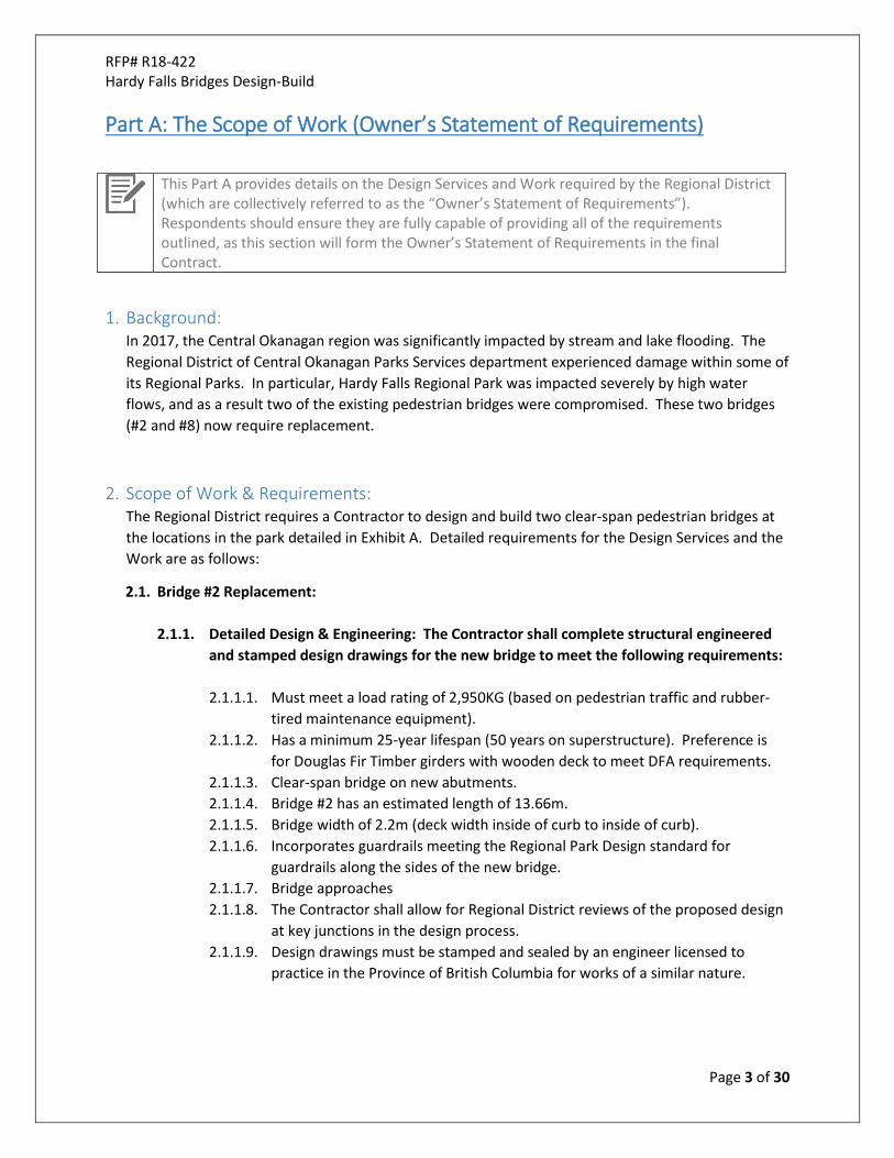
GC 6.5 DELAYS
SGC 15. Add paragraphs 6.5.6, 6.5.7 and 6.5.8 as follows:
6.5.6 If the Owner determines that the Design-Builder is delayed in the performance of the Work, for reasons other than those under GC6.5.1, GC6.5.2 or GC6.5.3, such that in the Owner’s opinion the Work is more than 20 percent behind the Construction Schedule, then upon notice from the Owner, the Design-Builder will increase the hours of work, the days of work, and the number of workers as required to bring the Work back into line with the Construction Schedule and any costs associated with such measures shall be borne by the Design-Builder.
6.5.7 In the event of any delay the Design-Builder shall take all reasonable measures to minimize the effects and costs of the delay and (except where the delay is caused by the Owner or the Payment Certifier or other cause reasonably outside of the control of the Design-Builder) the Design-Builder will be responsible for all costs relating to the delay.
6.5.8 The Design-Builder shall maintain and protect the Work during the period of delay in the performance of the Work.
GC 7.3 DESIGN-BUILDER’S RIGHT TO SUSPEND THE DESIGN SERVICES OR WORK, OR TERMINATE THE CONTRACT
SGC 16. Delete entirely paragraph 7.3.3.1
SGC 17. Replace paragraph 7.3.6 with the following:
“7.3.6 If the Design-Builder terminates the Contract under the conditions set out above, the Design-Builder shall be entitled to be paid for all work performed under the Contract including reasonable profit and will be entitled to no further compensation from the Owner.”
GC 9.4 CONSTRUCTION SAFETY
SGC 18. Delete paragraph 9.4.1 and replace with the following:
9.4.1 The Design-Builder shall be solely responsible for construction safety at the Place of the Work as and to the extent required by applicable legislation, regulations and codes, including the Workers Compensation Act, applicable regulations and good construction practice, and shall be responsible for initiating, maintaining and supervising all safety precautions and programs in connection with the performance of the Work.

RFP# R18-422 Hardy Falls Bridges Design-Build
Page 20 of 30
GC 10.1 TAXES AND DUTIES
SGC 19. Add paragraph 10.1.3 as follows:
10.1.3 Any tax including, without limiting the generality of the foregoing, the Value-Added Tax or any government sales tax, customs, duty or excise tax, whether paid or not, which is found to be inapplicable or for which exemption may be obtained is, the sole and exclusive property of the Owner. The Design-Builder agrees to cooperate with the Owner or his agent in the application for any refund of any such taxes, which cooperation shall include without limitation making or concurring in the making of application for any such refund or exemption and providing to the Owner or his agent copies, or where required, originals, or records, invoices, purchase orders and other documentation necessary to support such application for exemption or refund.
SGC 20. Add paragraph 10.1.4 as follows:
10.1.4 Where any invoices or other documents are required for tax and duty refund purposes, the Design-Builder shall provide the Owner with such invoices and other documents as may be necessary to substantiate the amount of taxes or duties paid during the performance of the Contract for which the Owner may rightfully claim redemption.
GC 10.2 LAWS, NOTICES, PERMITS AND FEES
SGC 21. GC 10.2.6 Delete the words “knowing it to be” in the second line of paragraph 10.2.6 and replace them with “that is”.
SGC 22. Add the following paragraph: 10.2.8 The Design-Builder will notify and deal with organizations involved with or
affected by the Work, such as telephone, electricity, gas and other utility providers, railway companies and government agencies.
GC 10.4 WORKERS’ COMPENSATION
SGC 23. Add paragraph 10.4.3 as follows: 10.4.3 The Design-Builder shall indemnify and hold harmless the Owner from all manner of
claims, demands, damages, costs, losses, penalties, actions, causes of action and proceedings arising out of or in any way related to unpaid WorkSafe BC assessments owed by any person working on the Project or relating to the Work or arising out of or in any way related to the failure to observe safety rules, regulations and practices of WorkSafe BC.

RFP# R18-422 Hardy Falls Bridges Design-Build
Page 21 of 30
SGC 24. Add paragraph 10.4.4 as follows: 10.4.4 The Design-Builder will be the “Prime Contractor” for the Project under the Workers
Compensation Act (British Columbia) and will fulfill all obligations of the “Prime Contractor” under that Act, including by ensuring that the activities of any employees, workers and other persons at the Place of the Work relating to occupational health and safety are coordinated and by doing everything that is reasonably practicable to establish and maintain a system or process that will ensure compliance with the Workers Compensation Act and the regulations under that Act applicable to the Place of the Work”.
GC 11.1 INSURANCE SGC 25. Add paragraph 11.1.1.9 as follows:
11.1.1.9 Contractor’s Pollution Liability or Environmental Impairment Liability with a limit of not less than One Million ($1,000,000.00) Dollars per occurrence for claims arising from bodily injury, death, or property damage caused or alleged to be caused by a spill, discharge, emission, dispersal, seepage, leakage, migration, release or escape of pollutants in or upon land, the atmosphere, drainage or sewage system, watercourse or body of water arising out of the performance of this contract.
GC 12.5 WARRANTY
SGC 26. Delete paragraph 12.5.1 in its entirety and replace with the following:
Except for extended warranties as described in paragraph 12.5.6, the warranty period under the Contract is five years from the date of Substantial Performance of the Work.
SGC 27. Add the following sentence to paragraph 12.5.5:
In effecting a correction of defects or deficiencies, the Design-Builder shall also bear all costs involved in removing, replacing, repairing or restoring aspects of the Work that may be affected in the process of making the correction.
SGC 28. Add paragraph 12.5.9 as follows:
12.5.9 Where a material, product or installation covered by warranty fails, the stipulated warranty and warranty period shall be renewed for the specific work being replaced or repaired,

RFP# R18-422 Hardy Falls Bridges Design-Build
Page 22 of 30
Part D: Submission Forms
This Part D contains forms detailing the information that should be included in a Proposal, as detailed under Section 6 of Part B.
Part D Contents: This Part D contains the following forms:
Appendix A – Certification Form Appendix B – Pricing Form Appendix C – Methodology, Schedule and Team Form Appendix D – Experience Form Appendix E – Subcontractors Form

RFP# R18-422 Hardy Falls Bridges Design-Build
Page 23 of 30
APPENDIX A – CERTIFICATION FORM
Respondents must complete all details requested in this Appendix A – Certification Form and include this completed form in the Proposal, as detailed under Section 6.1 (Mandatory Criteria) of Part B. No changes to this form must be made, except for completing the requested information in the spaces provided.
1. Respondent Details:
Full Legal Name of Respondent:
Other “DBA” Names the Respondent Uses:
Registered Address: Respondent Contact Person Name & Title:
Contact Person Phone No.: Contact Person Email:
2. Certification & Acknowledgement of RFP Process:
By signing this Appendix A – Certification Form, we the Respondent, certify and acknowledge the following:
a. We have carefully read and examined this RFP document, including all Parts and Appendices, and have conducted such other investigations as were prudent and reasonable in preparing this Proposal. We are able to perform the Design Services and the Work detailed in Part A for the pricing submitted in this Proposal.
b. We certify that the statements made in this Proposal are true and submitted in good faith. c. We acknowledge and understand that the RFP process and the submission of this Proposal do
not give rise to any contractual obligations whatsoever (including what is commonly referred to as ‘Contract A’) between the Regional District and us, the Respondent, and that no contractual obligations shall arise between the Regional District and us, the Respondent, until and unless we execute a written Contract with the Regional District.
d. We certify that in relation to this RFP process, we have not engaged in any conduct which would constitute a conflict of interest and we understand that a conflict of interest would include the following situations:
i. The Respondent has an unfair advantage or engages in conduct which may give it an unfair advantage;
ii. The Respondent has had access to confidential information of the Regional District which is not available to other Respondents to this RFP.

RFP# R18-422 Hardy Falls Bridges Design-Build
Page 24 of 30
iii. The Respondent has influence over an employee of the Regional District who is a decision-maker involved in this RFP process, which could reasonably be perceived as giving the Respondent an unfair advantage or preferential treatment.
3. Confirmation of Addenda Received:
We confirm receipt of the following addenda that were issued by the Regional District up until the Closing Date and Time:
Addendum # Issued On Date:
4. Certification Signature:
The Respondent hereby certifies that the above statements are true and that the individual signing below has the authority to bind the Respondent:
__________________________________ Signature of Respondent Representative
__________________________________ Name of Respondent Representative
__________________________________ Title of Respondent Representative
____________ Date

RFP# R18-422 Hardy Falls Bridges Design-Build
Page 25 of 30
APPENDIX B – PRICING FORM
Respondents must complete the requested pricing in all tables in this Appendix B – Pricing Form and include the completed form in the Proposal, as detailed under Section 6.2 (Scored Criteria) of Part B. No changes to this form must be made, except for completing the requested information in the spaces provided.
1. Pricing Basis: Pricing entered into the tables of section 2 and 3 below, shall be on the following basis:
a. All Prices are in Canadian funds, are inclusive of all applicable duties and taxes including the PST, but not the GST which shall be itemized separately where indicated.
b. Stipulated Lump Sum Prices are all-inclusive and include for all labour, materials, supplies, travel, overheads, profit, insurance, expenses, disbursements, mobilization/demobilization, and all other costs and fees necessary to perform the Scope of Work outlined in Part A.
c. Prices shall be fixed for the entire Contract term. d. Pricing shall be based on the Regional District awarding all Work for both bridges to one
Contractor only. The Regional District does not intend to split the Work.

RFP# R18-422 Hardy Falls Bridges Design-Build
Page 26 of 30
2. Stipulated Lump Sum Prices: For completion of all Design Services and Work as detailed in Part A, the Stipulated Contract Price shall be broken down as follows:
Item #
Scope of Work Item Stipulated Lump Sum Price
BRIDGE #2 Replacement: 1 Detailed Design & Engineering: $
Construction & Installation: 2 Mobilization / Demobilization $
3 Project Management, including site access and security $
4 Environmental Controls $
5 Clearing & grubbing $
6 Construction & Installation of new bridge $
7 Construction of bridge approaches $
8 Site Clean-up & Remediation $
9 Any Other Costs (specify if any): $
10 Sub-total for Bridge #2 Replacement (Sum of Items 1 to 9)
$
BRIDGE #8 Replacement: 11 Detailed Design & Engineering: $ Construction & Installation: 12 Mobilization / Demobilization $
13 Project Management, including site access and security $
14 Environmental Controls $
15 Clearing & grubbing $
16 Construction & Installation of new bridge $
17 Construction of bridge approaches $
18 Site Clean-up & Remediation $
19 Any Other Costs (specify if any): $
20 Sub-total for Bridge #8 Replacement (Sum of Items 11 to 19)
$
21 TOTAL STIPULATED CONTRACT PRICE:
(SUM OF ITEMS 10 & 20) $
22 GST @5%: $

RFP# R18-422 Hardy Falls Bridges Design-Build
Page 27 of 30
3. Prices for Optional Extra Work: If the Regional District elects to add the Optional Extra Work to the Work, the following prices shall be added to the Stipulated Lump Sum Prices detailed in Section 2 of this Appendix B.
Item #
Optional Extra Work Items Lump Sum Price
Optional Extra Work - BRIDGE #2 Replacement: 1 Use Weathering steel girders instead of Douglas Fir Timber
girders ADD $
2 Any Other Costs (specify if any): ADD $
3 Sub-total for Optional Extra Work for Bridge #2 Replacement: ADD $ Optional Extra Work - BRIDGE #8 Replacement: 4 Use Weathering steel girders instead of Douglas Fir Timber
girders ADD $
5 Any Other Costs (specify if any): ADD $
6 Sub-total for Optional Extra Work for Bridge #8 Replacement: ADD $
4. Payment Terms:
The Total Stipulated Contract Price shall be paid by the Owner to the Contractor in a series of progress payments, which will be invoiced by the Contractor at monthly intervals, on the last day of each month.
Progress Payments shall be made in accordance with the provisions of the Contract.

RFP# R18-422 Hardy Falls Bridges Design-Build
Page 28 of 30
APPENDIX C – METHODOLOGY, SCHEDULE AND TEAM FORM
Proposals should include, in a format of your choice, the details requested in this Appendix C – Methodology, Schedule & Team Form, as detailed under Section 6.2 (Scored Criteria) of Part B. This section of your Proposal must be labelled as “Appendix C – Methodology, Schedule & Team Form”. Evaluation Factors: Factors to be considered during the evaluation in assessing suitability of methodology, schedule and team will include:
• Demonstration that the Respondent understands key aspects of the Work required and factors to be considered;
• Experience and expertise of the proposed team; and • Suitability of the schedule proposed.
1. Methodology: Please provide, in the space below, details of the methodology to be employed by your firm and Subcontractors (if applicable) to perform the Design Services and Scope of Work outlined in Part A:
2. Schedule: Please provide, in a format of your choice and preferably a gantt chart or similar, details of your proposed schedule for completing the Work. This should identify all key steps and milestones.
3. Team: Please provide, in the space below, details of the team members from your firm, and from Subcontractors (if applicable), that will perform the Scope of Work outlined in Part A. Please also attach a resume for each names team member which provides and overview of their education and experience relevant to delivering the Service.
Team Member Name: Position: Design Engineer Project Manager Site Superintendent

RFP# R18-422 Hardy Falls Bridges Design-Build
Page 29 of 30
APPENDIX D – EXPERIENCE FORM
Proposals should include, in a format of your choice, the details requested in this Appendix D – Experience Form, as detailed under Section 6.2 (Scored Criteria) of Part B. Respondents should provide details on 3 projects completed in the last 5 years which are the most relevant and similar to the Services. Respondents should note that the Regional District may contact the client to provide a reference on the experience listed (including amending scoring in the evaluation based on the client’s feedback). Evaluation Factors: Factors to be considered during the evaluation in assessing suitability of experience will include:
• Suitability of experience with similar work and projects; • Feedback from Client references, if the Regional District chooses to contact
references; and • The Regional District’s own experience.
Project Experience #1
Client Company Name: Project Name: Date Respondent Started Work on Project: Date Respondent Finished Work on Project: Brief Description of Project and Services Respondent Performed:
Value of Respondent Contract on this Project (excluding GST):
Project Experience #2
Client Company Name: Project Name: Date Respondent Started Work on Project: Date Respondent Finished Work on Project: Brief Description of Project and Services Respondent Performed:
Value of Respondent Contract on this Project (excluding GST):
Project Experience #3
Client Company Name: Project Name: Date Respondent Started Work on Project: Date Respondent Finished Work on Project: Brief Description of Project and Services Respondent Performed:
Value of Respondent Contract on this Project (excluding GST):

RFP# R18-422 Hardy Falls Bridges Design-Build
Page 30 of 30
APPENDIX E – SUBCONTRACTORS FORM
Proposals should include, in a format of your choice, the details requested in this Appendix E – Subcontractors Form, as detailed under Section 6.2 (Scored Criteria) of Part B. Respondents should use this form to provide details on any Subcontractors to be used in performing the Services. Respondents should note that any Subcontractor which is not named in the Appendix E submission cannot be used in delivering the Service. Evaluation Factors: Factors to be considered during the evaluation in assessing suitability of subcontractors will include:
• Suitability of the work to be subcontracted-out.
Part of Work to be Performed Legal Name of Subcontractor

_̂
_̂
_̂
_̂
_̂
_̂
_̂
_̂
Peachland Creek
Bridge #1
Bridge #3
Bridge #4
Bridge #5
Bridge #6
Bridge #7
Bridge #8
Bridge #2
Hardy FallsRegional
ParkTh
orne
Rd
Hardy St
Bulyea Ave
Hardy Falls Regional Park - Overview Map
0 10 20 30 40 50 60 705Meters
Coordinate System: NAD 1983 UTM Zone 11N
Product: Aerial Survey Overview MapClient: RDCOUAV Consulted: TSAMap Created: 07/05/2018Data Sources: RDCO, TSA
Legend
1:1,000
Park Boundary
UAV Data Extent
Peachland Creek
Hiking Trail
Roads_̂ Bridge Location
EXHIBIT A - SITE MAP

,,, !bl (OJ (dl �•> ,,, (g) (h) ,q
Wl11t Vihlt callfl,d the
OHCribt Wh,at w,as d:ima9c11I (materials, Dos-crib� the rcp�r v,"Od( re,q!Jittd to !'Nto,_ to Oesc:ribe the mati:riaJs, including quentitlit&
PIOJOCI # Oti. 01 damage Si:c tOGation infrt.t\l'\ltlu,. was damtgc? oe,crib4 1no ctam.igo includlnv qu:11ttitio. and l'll••�ll'lt(IU pl'Cl◄Yant condition ,.M mNsur.men-tJ, lo ,-p1dr to p�.cvent
dama;od? Of d�au•d lnfrufructi.o conditiOl'I
,., 5 M11y2017 ID 5 Hardy Falls BMg:¢$ #2 ,;ind f8 Eic11eme higl\ w11t.et 8ridge #2 uad#3.,..'Clrc hea� Btllh Bfidge #2 and ff ware Clls,fll11c!MI ITom CC11ff111$' .see1ion 11 awrOY111s fOt �.J0\/8l and fld!m!i !2 & !ft;• iSNT l!!!51ineeri!!Q)
J.ine20t7 Regional Ptut. fl�inDc,ep �t1'18g&d due lo ll()Qd vr.ittrs !Mil abu'me111ts. lt-.e Sll'U�Jral re,pl8C.fl'll)ni ct 111e «:ds!ing bridges u:iinig COflllultafll Re<no�e. OuiQ,\ & RGl)IOOC 8rid11cs & gel I (Pt&e:1-.andJ Cn�ek ffOdif'lg '""' ··� tto'Jnd lM co,r"°',enu qt,,, brid9Cs have �n auitlllt'ICa comi:1a.e .-. rcpl;u;cmon: of �rid9c, #2 StdiOl'I 11 Af>proval�. See SNT Report 6.2-2 I
cte111e<1 sedment ar.cl b;idge .ibulmenls, 8otll pieced utldet signi!lcarA $!rain .ind rc(JJire and t8 :,nd bbi;tmel'lts... Brid'Q(l ltf'l!Jlh8 -M\I b$ (#2) aid6,2.S(#8) hr d11m;ige, ��ir. I
c:litbr,s �ms which bridges klsl flelr ab1;..-,<Jn,;s repl11Cffl'W!nt. Tt-..e �f«l hev• b .. n �aff'd » ;o:orntr.od.l111 c:ha�es tCJ wearn '
IOC'Ced W'IUCr 01.1;1:lc Mid' s.��m Cl'l8Mel wid1t! tor 8'0Cl•::I an;IQ;wn;iged :md !IT.e �lrHtn Ch8"lllel..._.,th. Tll• lncr4t1Sltlrl hin;b"M11 be mo,c See e041 l;retikcbwn labl• c«wloeid, .ind $NT '
1cpec l>Sl'lk b:M b.itlgu h:is SiQf'li(ieat'llly ChaMel 'A((l1h intrtaM wll require ii 10flQCf a(-lcrd:lble tllM re-est&bli&hil'IQ II• Prt•nood Str$am Det�lcd Co.s.1 Esiimalc Apptr.dix 'A' on Paga 2 inue.a,ed. �p11n rcpillc:tmenl hti�e. 8ridQ8 t2 It ehanncl �th. tn .ic'di!ion. efMrO,iment31 J>181JoM ar.d 4. !-':er 1,11;:<k11Ji$ Se• rcvisc6StlT repol't,
7.◄7m lon;a :c 2,2m wiCc 11r.d c:ot1Sln.ic:t&d wit likety �Ol i,em,h Iha rebuilQing of the Arcam l.brth 8, 2018 out ot rough C\11 Ooug\;li fi r, and sJTing-on b:mk.s l.:i pre•IIOOCI eol'IOllioni. 1.0m x 2..0m g�biOn tti\el8bu11'1'1Qnts. 8rid;• A'3 is 7.92m Ieng• 2.2't'lh•,ide and COMtfUCted ovt o( n)U;h cul Douglas b-,
af\d ailling on 1,0:n:c 2,0m g:ibioon b:iskot .:ibatments.
.. . . . --... . � �-►�- - ---
EXHIBIT B

HEALTH & SAFETY ASSESSMENTS – PARKS FLOOD DAMAGE
LOT A - STRUCTURAL ASSESSMENT OF 8 REGIONAL PARKS SPRING 2017 FRESHET FLOODING EVENTS REGIONAL DISTRICT OF CENTRAL OKANAGAN, FILE No. R17-373
Submitted to:
Wayne Darlington, Manager – Park Planning/Capital Projects/Visitor Services Parks Services, Regional District of Central Okanagan 1450 K.L.O Road, Kelowna, BC V1W 3Z4 By email: [email protected]
Submitted by:
SNT Engineering Ltd. Suite #3, 385 Baker St. Nelson, BC VIL 4H6 Email: [email protected]
December 19, 2017
EXHIBIT C
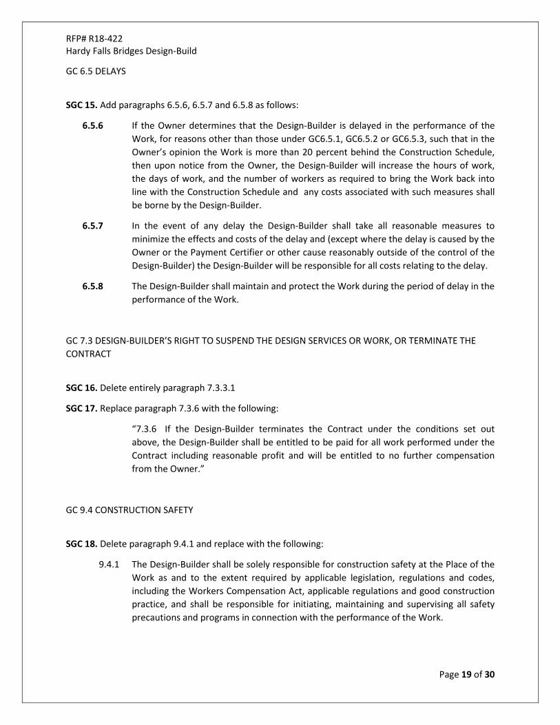
HEALTH & SAFETY REVIEW – PARKS FLOOD DAMAGE LOT A - STRUCTURAL ASSESSMENT OF 8 REGIONAL PARKS
Page 2 of 111
Table of Contents
1 INTRODUCTION ................................................................................................................................................. 12
1.1 BACKGROUND .......................................................................................................................................... 13
2. METHODOLOGY ................................................................................................................................................ 13
3. KILLINEY BEACH COMMMUNITY PARK ............................................................................................................ 14
3.1 BACKGROUND .......................................................................................................................................... 14
3.1.1 Location ................................................................................................................................................ 14
3.1.2 HISTORY ............................................................................................................................................... 14
3.1.3 Event and Damage Overview .............................................................................................................. 14
3.2 DAMAGE ASSESSMENT ........................................................................................................................... 15
3.2.1 Site #1 Boat Launch ............................................................................................................................. 15
3.2.2 Site #2 Dock.......................................................................................................................................... 18
3.3 REMEDIATION PLAN ................................................................................................................................ 22
3.3.1 Repairing Sites to Pre-Flood Event Condition .................................................................................... 22
3.3.2 Cost Estimate For Repairing Sites to Pre-Flood Event Condition ...................................................... 22
3.3.3 Assessment of Alternative Options .................................................................................................... 23
3.4 RECOMMENDATIONS .............................................................................................................................. 23
4. OKANAGAN CENTRE SAFE HARBOUR REGIONAL PARK .................................................................................. 24
4.1 BACKGROUND INFORMATION ............................................................................................................... 24
4.1.1 Location ................................................................................................................................................ 24
4.1.2 History .................................................................................................................................................. 24
4.1.3 Event and Damage Overview .............................................................................................................. 24
4.2 DAMAGE ASSESSMENT ........................................................................................................................... 25
4.2.1 Site #1 Boat Launch ............................................................................................................................. 25
4.2.2 Site #2 Boat Dock ................................................................................................................................. 28
4.2.3 Site #3 Old Boat Launch ...................................................................................................................... 30
4.2.4 Site #4 Pedestrian/Fishing Dock ......................................................................................................... 30
4.2.5 Site #5 South & North Breakwaters.................................................................................................... 33
4.2.6 Site #6 Gangway .................................................................................................................................. 34
4.2.7 Site #7 Parking Area ............................................................................................................................. 35
4.3 REMEDIATION PLAN ................................................................................................................................ 36
4.3.1 Repairing Sites to Pre-Flood Event Condition .................................................................................... 36
4.3.2 Cost Estimate For Repairing Sites to Pre-Flood Event Condition ...................................................... 36

HEALTH & SAFETY REVIEW – PARKS FLOOD DAMAGE LOT A - STRUCTURAL ASSESSMENT OF 8 REGIONAL PARKS
Page 3 of 111
4.4 RECOMMENDATIONS .............................................................................................................................. 37
5. WOODHAVEN NATURE CONSERVANCY REGIONAL PARK .............................................................................. 38
5.1 BACKGROUND INFORMATION ............................................................................................................... 38
5.1.1 Location ................................................................................................................................................ 38
5.1.2 History .................................................................................................................................................. 38
5.1.3 Event and Damage Overview .............................................................................................................. 38
5.2 DAMAGE ASSESSMENT ........................................................................................................................... 39
5.2.1 Site #1 Vehicle Bridge .......................................................................................................................... 39
5.3 REMEDIATION PLAN ................................................................................................................................ 42
5.3.1 Repairing Sites to Pre-Flood Event Condition .................................................................................... 42
5.3.2 Cost Estimate For Repairing Sites to Pre-Flood Event Condition ...................................................... 42
5.3.3 Assessment of Alternative Options .................................................................................................... 43
5.4 RECOMMENDATIONS .............................................................................................................................. 44
6. HARDY FALLS REGIONAL PARK ......................................................................................................................... 45
6.1 BACKGROUND INFORMATION ............................................................................................................... 45
6.1.1 Location ................................................................................................................................................ 45
6.1.2 History .................................................................................................................................................. 45
6.1.3 Event and Damage Overview .............................................................................................................. 45
6.2 DAMAGE ASSESSMENT ........................................................................................................................... 47
6.2.1 Site #1 Bridge #1 .................................................................................................................................. 47
6.2.2 Site #2 Bridge #2 .................................................................................................................................. 49
6.2.3 Site #3 Bridge #3 .................................................................................................................................. 52
6.2.4 Site #4 Bridge #4 .................................................................................................................................. 53
6.2.5 Site #5 Bridge #5 .................................................................................................................................. 55
6.2.6 Site #6 Bridge #6 .................................................................................................................................. 56
6.2.7 Site #7 Bridge #7 .................................................................................................................................. 58
6.2.8 Site #8 Bridge #8 .................................................................................................................................. 59
6.2.9 Site #9 Viewing Platform ..................................................................................................................... 61
6.3 REMEDIATION PLAN ................................................................................................................................ 63
6.3.1 Repairing Sites to Pre-Flood Event Condition .................................................................................... 63
6.3.2 Cost Estimate For Repairing Sites to Pre-Flood Event Condition ...................................................... 64
6.3.3 Assessment of Alternative Options .................................................................................................... 65
6.4 RECOMMENDATIONS .............................................................................................................................. 67
7. GLEN CANYON REGIONAL PARK ....................................................................................................................... 68
7.1 BACKGROUND INFORMATION ............................................................................................................... 68

HEALTH & SAFETY REVIEW – PARKS FLOOD DAMAGE LOT A - STRUCTURAL ASSESSMENT OF 8 REGIONAL PARKS
Page 4 of 111
7.1.1 Location ................................................................................................................................................ 68
7.1.2 History .................................................................................................................................................. 68
7.1.3 Event and Damage Overview .............................................................................................................. 68
7.2 DAMAGE ASSESSMENT ........................................................................................................................... 69
7.2.1 Site #1 Brown Road Bridge .................................................................................................................. 69
7.2.2 Site #2 Staircases ................................................................................................................................. 71
7.3 REMEDIATION PLAN ................................................................................................................................ 74
7.3.1 Repairing Sites to Pre-Flood Event Condition .................................................................................... 74
7.3.2 Cost Estimate For Repairing Sites to Pre-Flood Event Condition ...................................................... 74
7.4 RECOMMENDATIONS .............................................................................................................................. 74
8. FINTRY ACCESS #1 COMMUNITY PARK ............................................................................................................ 75
8.1 BACKGROUND INFORMATION ............................................................................................................... 75
8.1.1 Location ................................................................................................................................................ 75
8.1.2 History .................................................................................................................................................. 75
8.1.3 Event and Damage Overview .............................................................................................................. 75
8.2 DAMAGE ASSESSMENT ........................................................................................................................... 76
8.2.1 Site #1 Boat Launch ............................................................................................................................. 76
8.2.2 Site #2 Dock.......................................................................................................................................... 78
8.3 REMEDIATION PLAN ................................................................................................................................ 80
8.3.1 Repairing Sites to Pre-Flood Event Condition .................................................................................... 80
8.3.2 Cost Estimate For Repairing Sites to Pre-Flood Event Condition ...................................................... 80
8.3.3 Assessment of Alternative Options .................................................................................................... 81
8.4 RECOMMENDATIONS .............................................................................................................................. 81
9. MILL CREEK REGIONAL PARK ............................................................................................................................ 82
9.1 BACKGROUND INFORMATION ............................................................................................................... 82
9.1.1 Location ................................................................................................................................................ 82
9.1.2 History .................................................................................................................................................. 82
9.1.3 Event and Damage Overview .............................................................................................................. 82
9.2 DAMAGE ASSESSMENT ........................................................................................................................... 83
9.2.1 Site #1 Footbridge................................................................................................................................ 83
9.2.2 Site #2 Vehicle Bridge .......................................................................................................................... 88
9.2.3 Site #3 Boardwalk ................................................................................................................................ 91
9.2.4 Site #4 Culvert ...................................................................................................................................... 93
9.3 REMEDIATION PLAN ................................................................................................................................ 94
9.3.1 Repairing Sites to Pre-Flood Event Condition .................................................................................... 94

HEALTH & SAFETY REVIEW – PARKS FLOOD DAMAGE LOT A - STRUCTURAL ASSESSMENT OF 8 REGIONAL PARKS
Page 5 of 111
9.3.2 Cost Estimate For Repairing Sites to Pre-Flood Event Condition ...................................................... 95
9.3.3 Assessment of Alternative Options .................................................................................................... 95
9.4 RECOMMENDATIONS .............................................................................................................................. 95
10. MISSION CREEK GREENWAY REGIONAL PARK ........................................................................................... 96
10.1 BACKGROUND INFORMATION ............................................................................................................... 96
10.1.1 Location ........................................................................................................................................... 96
10.1.2 History .............................................................................................................................................. 96
10.1.3 Event and Damage Overview ......................................................................................................... 96
10.2 DAMAGE ASSESSMENT ........................................................................................................................... 97
10.2.1 Site #1 Friends Footbridge .............................................................................................................. 97
10.2.2 Site #2 Cedars Footbridge ............................................................................................................. 100
10.2.3 Site #3 Boardwalks ........................................................................................................................ 102
10.2.4 Site #4 Smoothing Stones Footbridge .......................................................................................... 105
10.3 REMEDIATION PLAN .............................................................................................................................. 108
10.3.1 Repairing Sites to Pre-Flood Event Condition .............................................................................. 108
10.3.2 Cost Estimate For Repairing Sites to Pre-Flood Event Condition ............................................... 108
10.4 RECOMMENDATIONS ............................................................................................................................ 109
11. SUMMARY .................................................................................................................................................. 110
12. CLOSURE ..................................................................................................................................................... 111

HEALTH & SAFETY REVIEW – PARKS FLOOD DAMAGE LOT A - STRUCTURAL ASSESSMENT OF 8 REGIONAL PARKS
Page 6 of 111
List of Tables
Table 1: Damage Assessment Summary (Killiney Beach) ....................................................................................... 15 Table 2: Cost Estimate for Repairs to Pre-Flood Event Condition (Killiney Beach) ................................................ 22 Table 3: Damage Assessment Summary (Okanagan Centre Safe Harbour) .......................................................... 25 Table 4: Cost Estimate for Repairs to Pre-Flood Event Condition (Okanagan Safe Centre Harbour) ................... 37 Table 5: Damage Assessment Summary (Woodhaven Nature Conservancy) ....................................................... 39 Table 6: Cost Estimate for Repairs to Pre-Flood Event Condition (Woodhaven Nature Conservancy) ............... 43 Table 7: Cost Estimate for Repairs at Alternative Location (Woodhaven Nature Conservancy) .......................... 44 Table 8: Damage Assessment Summary (Hardy Falls) ............................................................................................ 46 Table 9 General Bridge Configuration ...................................................................................................................... 47 Table 10: Cost Estimate for Repairs to Pre-Flood Event Condition (Hardy Falls) ................................................... 65 Table 11: Damage Assessment Summary (Glen Canyon) ....................................................................................... 69 Table 12: Cost Estimate for Repairs to Pre-Flood Event Condition (Glen Canyon) ............................................... 74 Table 13: Damage Assessment Summary (Fintry Access #1) .................................................................................. 76 Table 14: Cost Estimate for Repairs to Pre-Flood Event Condition (Fintry Access #1) .......................................... 80 Table 15: Damage Assessment Summary (Mill Creek) ............................................................................................ 83 Table 16 General Bridge Configuration .................................................................................................................... 83 Table 17 General Bridge Configuration .................................................................................................................... 88 Table 18: Cost Estimate for Repairs to Pre-Flood Event Condition (Mill Creek) .................................................... 95 Table 19: Damage Assessment Summary (Mission Creek) ..................................................................................... 97 Table 20: Cost Estimate for Repairs to Pre-Flood Event Condition (Mission Creek) ........................................... 109 Table 21 Cost Estimate for Repairs to Pre-Flood Event Condition Summary ...................................................... 110
List of Maps Map 1: Overview RDCO Parks Map .......................................................................................................................... 12 Map 2 Killiney Beach Community Park .................................................................................................................... 14 Map 3 Okanagan Centre Safe Harbour Regional Park ............................................................................................ 24 Map 4 Woodhaven Nature Conservancy Regional Park – 979 Raymer Road ....................................................... 38 Map 5 Hardy Falls Regional Park .............................................................................................................................. 45 Map 6 Glen Canyon Regional Park ........................................................................................................................... 68 Map 7 Fintry Access #1 ............................................................................................................................................. 75 Map 8 Mill Creek Regional Park ................................................................................................................................ 82 Map 9 Mission Creek Greenway Regional Park – Phase 2 ...................................................................................... 96

HEALTH & SAFETY REVIEW – PARKS FLOOD DAMAGE LOT A - STRUCTURAL ASSESSMENT OF 8 REGIONAL PARKS
Page 7 of 111
List of Figures
Figure 1: Boat Launch and Dock ............................................................................................................................... 16 Figure 2: Drop off at End of Launch .......................................................................................................................... 16 Figure 3: Boat Launch ................................................................................................................................................ 16 Figure 4: Displaced Rocks, Voids Under Concrete ................................................................................................... 17 Figure 5: Gravel Washed Out at Approach .............................................................................................................. 17 Figure 6: Slippery Launch – No Traction ................................................................................................................... 17 Figure 7: Ramp and Abutment ................................................................................................................................. 18 Figure 8: First Dock Section and Ramp Damaged and Displaced ........................................................................... 19 Figure 9: Lifted Pile at South Outside Corner ........................................................................................................... 19 Figure 10: Lifted Dock Timbers ................................................................................................................................. 19 Figure 11: Damaged Joists on First Dock Section.................................................................................................... 20 Figure 12: Lifted Pile .................................................................................................................................................. 20 Figure 13: Batter Boards Damaged ......................................................................................................................... 20 Figure 14: Damaged Angle Brace ............................................................................................................................. 21 Figure 15: Ramp ......................................................................................................................................................... 21 Figure 16: Lifted Timber Piles ................................................................................................................................... 21 Figure 17: Okanagan Safe Harbour Overview.......................................................................................................... 26 Figure 18: Boat Launch and Courtesy Dock ............................................................................................................. 26 Figure 19: Boat Launch Approach ............................................................................................................................ 26 Figure 20: Void Under First Panel ............................................................................................................................. 27 Figure 21: Typical Panel Connection ........................................................................................................................ 27 Figure 22: Differential Settlement between 2nd and 3rd Panels .............................................................................. 27 Figure 23: Crack in 2nd Panel ..................................................................................................................................... 28 Figure 24: Courtesy Dock and Ramp ........................................................................................................................ 28 Figure 25: View Under Dock ..................................................................................................................................... 29 Figure 26: Courtesy Dock .......................................................................................................................................... 29 Figure 27: Location of Missing Cross Bracing ........................................................................................................... 29 Figure 28: Loose Rail .................................................................................................................................................. 30 Figure 29: Old Boat Launch ....................................................................................................................................... 30 Figure 30: Pedestrian/Fishing Dock from Boat Launch ........................................................................................... 31 Figure 31: Dock Railing and Decking ........................................................................................................................ 31 Figure 32: Damaged Ramp sitting on Rock .............................................................................................................. 31 Figure 33: Ramp Underside Connections................................................................................................................. 32 Figure 34: Loose Ballast Timbers .............................................................................................................................. 32 Figure 35: Loose Ballast Timbers .............................................................................................................................. 32 Figure 36: Pavement Breaking Up Under Ramp ...................................................................................................... 33 Figure 37: South Breakwater and Pedestrian/Fishing Dock ................................................................................... 33 Figure 38: South Breakwater .................................................................................................................................... 34 Figure 39: North Breakwater and Gangway ............................................................................................................ 34 Figure 40: Gangway ................................................................................................................................................... 35 Figure 41: Some Rotten Timbers .............................................................................................................................. 35 Figure 42: Parking Area ............................................................................................................................................. 36 Figure 43: Old Bridge ................................................................................................................................................. 39 Figure 44: Corrosion of Steel Members ................................................................................................................... 40 Figure 45: Corrosion of Steel Members ................................................................................................................... 40

HEALTH & SAFETY REVIEW – PARKS FLOOD DAMAGE LOT A - STRUCTURAL ASSESSMENT OF 8 REGIONAL PARKS
Page 8 of 111
Figure 46: Timber Frame, Deck, and Damaged Railing ........................................................................................... 40 Figure 47: Crossing Location from Right Bank ......................................................................................................... 41 Figure 48: Left Bank Upstream, Over Steepened Bank ........................................................................................... 41 Figure 49: Left Bank Downstream Erosion ............................................................................................................... 42 Figure 50: View of Crossing from Upstream ............................................................................................................ 42 Figure 51: Alternative Location – Looking Downstream ......................................................................................... 43 Figure 52: Bridge #1 Downstream Elevation ........................................................................................................... 48 Figure 53: Bridge #1 Right Bank Abutment .............................................................................................................. 48 Figure 54: Bridge #1 Right Bank Abutment Gabion Undermined .......................................................................... 48 Figure 55: Bridge #1 Right Bank Abutment Gabion ................................................................................................. 49 Figure 56: Bridge #1 Left Bank Abutment ................................................................................................................ 49 Figure 57: Bridge #2 Right Bank Approach, Channel Re-Routed ............................................................................ 50 Figure 58: Bridge #2 Upstream Elevation, Debris Blockage .................................................................................... 50 Figure 59: Bridge #2 Right Bank Erosion .................................................................................................................. 50 Figure 60: Bridge #2 Left Bank Approach ................................................................................................................. 51 Figure 61: Bridge #2 Right Bank Downstream ......................................................................................................... 51 Figure 62: Proposed Alternative Crossing Location ................................................................................................. 51 Figure 63: Bridge #3 Upstream Elevation, Stump in Channel ................................................................................. 52 Figure 64: Bridge #3 Left Bank Approach, Trail Washed out & Debris ................................................................... 52 Figure 65: Bridge #3 Debris and Marks on Upstream Girder .................................................................................. 53 Figure 66: Bridge #3 Right Bank Upstream Bearing ................................................................................................ 53 Figure 67: Bridge #4 Upstream Elevation, Debris Caught in Bridge ....................................................................... 54 Figure 68: Bridge #4 Right Bank Approach Trail Washed Out ................................................................................ 54 Figure 69: Bridge #4 Left Bank Abutment ................................................................................................................ 54 Figure 70: Bridge #5 Upstream Elevation ................................................................................................................ 55 Figure 71: Bridge #5 Right Bank Downstream Abutment Constricting Creek ....................................................... 55 Figure 72: Bridge #5 Right Bank Downstream Scour ............................................................................................... 56 Figure 73: Bridge #6 Upstream Elevation ................................................................................................................ 56 Figure 74: Bridge #6 Left Bank Approach ................................................................................................................. 57 Figure 75: Bridge #6 Left Bank Upstream Scour ...................................................................................................... 57 Figure 76: Bridge #6 Left Bank Downstream Riprap ............................................................................................... 57 Figure 77: Bridge #6 Right Bank Abutment .............................................................................................................. 58 Figure 78: Bridge #7 Downstream Elevation ........................................................................................................... 58 Figure 79: Bridge #7 Upstream Elevation ................................................................................................................ 59 Figure 80: Bridge #7 Right Bank Abutment .............................................................................................................. 59 Figure 81: Bridge #8 Left Bank Approach ................................................................................................................. 60 Figure 82: Bridge #8 Right Bank Approach .............................................................................................................. 60 Figure 83: Bridge #8 Left Bank, Channel Re-Routed Around Bridge ...................................................................... 60 Figure 84: Bridge #8 Right Bank Downstream Bearing ........................................................................................... 61 Figure 85: Bridge #8 Right Bank Shifted off Gabion Abutment .............................................................................. 61 Figure 86: Viewing Platform ..................................................................................................................................... 62 Figure 87: Hardy Falls ................................................................................................................................................ 62 Figure 88: Downstream Footing ............................................................................................................................... 62 Figure 89: Debris Upstream ...................................................................................................................................... 63 Figure 90: Upstream Elevation ................................................................................................................................. 69 Figure 91: Truss .......................................................................................................................................................... 70 Figure 92: Typical Bearing ......................................................................................................................................... 70

HEALTH & SAFETY REVIEW – PARKS FLOOD DAMAGE LOT A - STRUCTURAL ASSESSMENT OF 8 REGIONAL PARKS
Page 9 of 111
Figure 93: Scour on Right Bank ................................................................................................................................. 70 Figure 94: Staircase #2 Footing Elevation Sketch .................................................................................................... 71 Figure 95: Staircase #1 .............................................................................................................................................. 71 Figure 96: Staircase #2 from Bottom........................................................................................................................ 72 Figure 97: Staircase #2 Footings ............................................................................................................................... 72 Figure 98: Soil Already Pulling Away from Footing ................................................................................................. 72 Figure 99: Steep Bank Supporting Footing............................................................................................................... 73 Figure 100: Void Under Footing ................................................................................................................................ 73 Figure 101: Staircase #3 Footings ............................................................................................................................. 73 Figure 102: Boat Launch and Dock ........................................................................................................................... 77 Figure 103: Gaps between Panels ............................................................................................................................ 77 Figure 104: South Side Launch Protection and Upgrades ....................................................................................... 77 Figure 105: What’s Left of Dock and Ramp ............................................................................................................. 78 Figure 106: Piles and Cap Beams .............................................................................................................................. 78 Figure 107: Ramp Abutment .................................................................................................................................... 79 Figure 108: Ramp Concrete Footing ......................................................................................................................... 79 Figure 109: Broken Concrete Around Ramp Abutment ......................................................................................... 79 Figure 110: Downstream Elevation .......................................................................................................................... 84 Figure 111: Upstream Elevation, Tree Stump .......................................................................................................... 85 Figure 112: Damaged Timbers near Right Bank ...................................................................................................... 85 Figure 113: Upstream Girder Deflection .................................................................................................................. 85 Figure 114: Cracked Tie ............................................................................................................................................. 86 Figure 115: Right Bank Abutment ............................................................................................................................ 86 Figure 116: Left Bank Abutment ............................................................................................................................... 86 Figure 117: Right Bank Bearing ................................................................................................................................. 87 Figure 118: Right Bank Stair Footing Undermined .................................................................................................. 87 Figure 119: Right Bank Downstream Abutment Scoured ....................................................................................... 87 Figure 120: Upstream Elevation ............................................................................................................................... 88 Figure 121: Right Bank Approach ............................................................................................................................. 89 Figure 122: Ballast Timbers Rotten .......................................................................................................................... 89 Figure 123: Glulam Girder Rotten End ..................................................................................................................... 89 Figure 124: Left Bank Abutment in Creek ............................................................................................................... 90 Figure 125: Diaphragm at Center Span .................................................................................................................... 90 Figure 126: Left Bank Downstream Scour ................................................................................................................ 90 Figure 127: Left Bank Upstream Scour ..................................................................................................................... 91 Figure 128: Boardwalk .............................................................................................................................................. 91 Figure 129: Debris on East End of Boardwalk .......................................................................................................... 92 Figure 130: Rotten Timber Posts .............................................................................................................................. 92 Figure 131: Rotten Timber Posts .............................................................................................................................. 92 Figure 132: Culvert Inlets .......................................................................................................................................... 93 Figure 133: Culvert Upstream Elevation .................................................................................................................. 93 Figure 134: Damaged Culvert Inlet ........................................................................................................................... 94 Figure 135: Right Bank Approach – Rock Armour ................................................................................................... 98 Figure 136: Downstream Elevation .......................................................................................................................... 98 Figure 137: Left Bank Abutment ............................................................................................................................... 98 Figure 138: Typical Bearing ....................................................................................................................................... 99 Figure 139: Rotten Deck Planks ................................................................................................................................ 99

HEALTH & SAFETY REVIEW – PARKS FLOOD DAMAGE LOT A - STRUCTURAL ASSESSMENT OF 8 REGIONAL PARKS
Page 10 of 111
Figure 140: Left Bank Upstream Thin and Narrow Layer of Riprap, not Keyed in ................................................. 99 Figure 141: Left Bank Downstream Abutment ...................................................................................................... 100 Figure 142: Upstream Elevation ............................................................................................................................. 100 Figure 143: Left Bank Approach Armoured Rock .................................................................................................. 101 Figure 144: Left Bank Riprap ................................................................................................................................... 101 Figure 145: Left Bank Upstream Thin Layer of Superficial Riprap ....................................................................... 101 Figure 146: Left Bank Downstream Encroaches Creek ......................................................................................... 102 Figure 147: Right Bank Abutment .......................................................................................................................... 102 Figure 149: Boardwalk #1 Approach View ............................................................................................................. 103 Figure 150: Boardwalk #1 Elevation View .............................................................................................................. 103 Figure 151: Boardwalk #1 Footings and Underside of Deck ................................................................................. 103 Figure 152: Boardwalk #1 Handrail Rot.................................................................................................................. 104 Figure 153: Boardwalk #2 Elevation View .............................................................................................................. 104 Figure 154: Boardwalk #3 and #4 ........................................................................................................................... 104 Figure 155: Upstream Elevation ............................................................................................................................. 105 Figure 156: Right Bank Pier ..................................................................................................................................... 106 Figure 157: Left Bank Abutment ............................................................................................................................. 106 Figure 158: Left Bank Upstream Scour ................................................................................................................... 106 Figure 159: Left Bank Undermined ........................................................................................................................ 107 Figure 160: Right Bank Abutment .......................................................................................................................... 107 Figure 161: Pier and Back Channel at Right Bank .................................................................................................. 107

HEALTH & SAFETY REVIEW – PARKS FLOOD DAMAGE LOT A - STRUCTURAL ASSESSMENT OF 8 REGIONAL PARKS
Page 11 of 111
December 19, 2017 Our reference: RDCO-17-01 Manager – Park Planning/Capital Projects/Visitor Services Parks Services, Regional District of Central Okanagan 1450 K.L.O Road, Kelowna, BC V1W 3Z4 Attn: Wayne Darlington RE: Health & Safety Assessment – Lot A Structural Assessment – Parks Flood Damage Regional District of Central Okanagan, File No. R17-373 As requested by the Regional District of Central Okanagan (RDCO), SNT Engineering Ltd. (SNT) has prepared a structural damage assessment report for the following eight regional parks:
1. Killiney Beach Community Park, Vernon 2. Okanagan Centre Safe Harbour Regional Park, Lake Country 3. Woodhaven Regional Park, Kelowna 4. Hardy Falls Regional Park, Peachland 5. Glen Canyon Regional Park, West Kelowna 6. Fintry Access #1 Community Park, North Westside 7. Mill Creek Regional Park, Kelowna 8. Mission Creek Greenway Regional Park, Kelowna
The assessment was initiated due to the extreme freshet flooding that occurred in spring 2017.

HEALTH & SAFETY REVIEW – PARKS FLOOD DAMAGE LOT A - STRUCTURAL ASSESSMENT OF 8 REGIONAL PARKS
Page 12 of 111
1 INTRODUCTION This report summarizes the results of a field review performed during October 10th – 12th, 2017 by SNT. The Parks noted above are located throughout the RDCO from the Peachland area to the north end of Okanagan Lake. The figure below shows a location overview map.
Map 1: Overview RDCO Parks Map
Early inspections indicated damage to park infrastructure including bridges, boardwalks, stairs, docks, boat launches, and breakwaters. This report focuses on following features:
1. Killiney Beach Community Park one dock and one boat launch
2. Okanagan Centre Safe Harbour Regional Park two docks, two breakwaters, and two boat launches
3. Woodhaven Nature Conservancy Regional Park one vehicle bridge
4. Hardy Falls Regional Park eight footbridges, and one viewing platform
5. Glen Canyon Regional Park one footbridge, and three staircases
6. Fintry Access #1 Community Park

HEALTH & SAFETY REVIEW – PARKS FLOOD DAMAGE LOT A - STRUCTURAL ASSESSMENT OF 8 REGIONAL PARKS
Page 13 of 111
one dock and one boat launch 7. Mill Creek Regional Park
one footbridge, one vehicle bridge, and boardwalk 8. Mission Creek Greenway Regional Park
three footbridges, and three boardwalks Each park has been assessed and reported separately using consistent methodology and procedures. This report details the damage, provides a cost estimate for the replacement or repair to pre-existing condition, and provides recommendations for structure repair or replacement to ensure long term sustainability and user safety.
1.1 BACKGROUND The Regional District of Central Okanagan (RDCO) has commenced the process of applying for Disaster Financial Assistance (DFA) from Emergency Management BC. This Health and Safety Review – Structural Assessment of the affected regional parks will assist the RDCO in their funding application by providing recommendations and cost estimates for repairs to pre-flood event condition.
2. METHODOLOGY The following methodology was used during the structural assessment of flood damage:
1. Review of the BC Compensation and Disaster Financial Assistance Regulations. 2. Review of documents provided by the RDCO Parks Services. 3. Review meeting and discussion with Wayne Darlington at RDCO office in Kelowna. 4. Field review of flood affected and damaged structures on October 10th - 12th. 5. Preparation of photographic log and damage description. 6. Assessment of repairing infrastructure to the pre-existing condition. 7. Assessment of alternative options. 8. Cost estimates for repairing damage to the flood-damaged structures. 9. Prepare summary report.

HEALTH & SAFETY REVIEW – PARKS FLOOD DAMAGE LOT A - STRUCTURAL ASSESSMENT OF 8 REGIONAL PARKS
Page 45 of 111
6. HARDY FALLS REGIONAL PARK
6.1 BACKGROUND INFORMATION
6.1.1 LOCATION Hardy Falls is located in Peachland, just off of Highway 97, about 30 km South of Kelowna. The park features a short trail that leads to a viewing platform and waterfall. The trail crosses 8 footbridges over Deep Creek along the way. The park encompasses an area just over 6 hectares. The parks activities also include bird and wildlife watching, and viewing the Kokanee Salmon spawning during the fall.
Map 5 Hardy Falls Regional Park
6.1.2 HISTORY The 8 bridges are all timber construction, with similar length, configuration and abutments. Bridge #1 was replaced in 2009, and the other 7 bridges were replaced in 2012. Only the superstructure was replaced, and the existing bridge abutments were re-used. The park is currently closed to the public due to damage that occurred in spring of 2017. No repairs have been carried out to date.
6.1.3 EVENT AND DAMAGE OVERVIEW The damage caused by the spring 2017 flooding included two washed out bridges (#2 and #8) and bridge abutment scour at other sites. A summary of the damage that occurred at each of the sites is shown in Table 8. A detailed discussion is provided in Section 6.2.

HEALTH & SAFETY REVIEW – PARKS FLOOD DAMAGE LOT A - STRUCTURAL ASSESSMENT OF 8 REGIONAL PARKS
Page 46 of 111
Table 8: Damage Assessment Summary (Hardy Falls)
Site # Name Description Present Condition 1 Bridge #1 7.34 m o/o (out to out)
timber footbridge Right bank abutment undermined, became worse during
flooding. Gabion too short for bridge, could settle and become unstable over time. Debris under gabion.
Bridge is too short for crossing. Bridge appears safe, no major damage due to flood. Estimated clearance (underside of girder to present water
level): 1370 mm 2 Bridge #2 7.47 m o/o timber
footbridge Bridge washed out during flooding, creek taken new route
around left bank abutment. Opening under bridge is plugged with debris. Existing bridge is too short for crossing location. Estimated clearance 680 mm.
3 Bridge #3 7.92 o/o m timber footbridge
Trail washed out at both approaches due to high water. Stump in creek upstream, blocking the flow and plugging the
bridge opening. Debris caught in ties, marks on upstream girder. Trail is washed out on both approaches. Bridge appears safe, no major damage due to flood. Estimated clearance: 840 mm.
4 Bridge #4 8.23 m o/o timber footbridge
Trail washed out at both approaches due to high water. Debris stuck in bridge ties, marks on upstream girder. Right bank sill sitting on soil. Bridge appears to be well anchored into abutments. Bridge is constricting creek, not enough clearance and too
short of span. Bridge appears safe, no major damage due to flood. Estimated clearance: 640 mm.
5 Bridge #5 8.23 m o/o timber footbridge
Right bank gabion basket undermined. Scour behind right bank downstream ballast wall and sill overhanging. Gabion encroaches channel.
Left bank appears fine. Bridge appears safe, no major damage due to flood. Estimated clearance: 780 mm.
6 Bridge #6 7.92 m o/o timber footbridge
Scour on left bank upstream side of bridge. Bridge appears safe, no major damage due to flood. Estimated clearance: 800 mm.
7 Bridge #7 7.92 m o/o timber footbridge
Bridge appears safe, no major damage due to flood. Estimated clearance: 970 mm.
8 Bridge #8 7.92 m o/o timber footbridge
Bridge washed out completely during flooding, creek taken new route and widened channel.
Right bank shifted 1.5 m downstream off footings. Right bank ballast wall timber and sill damaged, ties lifted. Bridge sitting on rock filled gabion baskets, not anchored in. Trail washed out behind right bank abutment. Estimated clearance: 950 mm.
9 Viewing Platform Timber platform on timber post footings.
Two footings, timber post on saddle and dowel into rock. Downstream side footing doesn’t appear stable (not sitting on flat rock) but likely an as-built condition.
Debris gathered near platform.

HEALTH & SAFETY REVIEW – PARKS FLOOD DAMAGE LOT A - STRUCTURAL ASSESSMENT OF 8 REGIONAL PARKS
Page 47 of 111
6.2 DAMAGE ASSESSMENT A field review was completed on October 10th, 2017 by Les Thiessen, P.Eng., and Teresa Cutler, E.I.T. of SNT. The general infrastructure damage was a result of high flows in Deep Creek and limited hydrologic capacity of the structures. A location map showing the sites relative to the park layout is provided in Map 5. The design of the recently replaced 8 bridges followed a similar configuration with timber girders, timber deck and railings. The existing rock filled gabion abutments were already in place from the previous structures. Some abutments were not well suited for the crossings and resulted in deficient creek clearance and encroachment. As a result, several structures were breached during the flood event, but the new timber superstructures alone did not sustain damage. Table 9 General Bridge Configuration
6.2.1 SITE #1 BRIDGE #1 The first bridge is slightly different than the other seven structures, see Table 9. A levelling base was added on top of the gabions. The gabion basket abutments are too short for the bridge width. The right bank gabion is being undermined. There is debris under the gabion, and water flows underneath. This may have been worsened by the tree down in the creek directing flow at the right bank gabion. The sill which the bridge is bearing on is not set back far enough from the creek edge. This could be potentially unstable over time which would compromise bridge safety. The right bank erosion appears to be a chronic issue for several years but likely worsened during the highwater flows. The bridge length is too short by about 1000 mm given the abutment configuration. The clearance from present water level to underside of girders is approximately 1370 mm. The present water depth was 200 mm and 4000 mm wide.
Bridge #1 Size (mm) Overall length 7340 Deck width 2200 inside curbs Deck planks 60x150 Ties 100x150 @ 450 c/c Girders 200x460 @ 600 c/c Bridge # 2 through #8 Size (mm) Overall length 7470 (Bridge #2)
7920 (Bridges #3, #6, #7 & #8) 8230 (Bridges #4 & #5)
Deck width 2200 inside curbs Deck planks 75x150 Ties 100x150 @ 500 c/c Girders 200x400 @ 600 c/c Abutments Size (mm) 50x150 ballast wall timbers (4)
150x300 timber sill 1000x2000 rock filled gabion baskets 1500x600x87 precast concrete footing on top of gabions (only Bridge #7, #8)

HEALTH & SAFETY REVIEW – PARKS FLOOD DAMAGE LOT A - STRUCTURAL ASSESSMENT OF 8 REGIONAL PARKS
Page 48 of 111
Figure 52: Bridge #1 Downstream Elevation
Figure 53: Bridge #1 Right Bank Abutment
Figure 54: Bridge #1 Right Bank Abutment Gabion Undermined
Tree directing flow towards right bank gabion.

HEALTH & SAFETY REVIEW – PARKS FLOOD DAMAGE LOT A - STRUCTURAL ASSESSMENT OF 8 REGIONAL PARKS
Page 49 of 111
Figure 55: Bridge #1 Right Bank Abutment Gabion
Figure 56: Bridge #1 Left Bank Abutment
6.2.2 SITE #2 BRIDGE #2 During the event, the footbridge #2 was completely washed out. The opening became plugged and blocked with debris. The channel rerouted around the right bank abutment, and split into two channels downstream. The right bank gabion has been displaced, and the bridge is now bearing on soil at the right bank. The clearance from the underside of the girder to present water level is 680 mm, measured at the downstream side. The present water level is approximately 200 mm deep. Due to the wash out, the bridge is now too short for the existing crossing. The left bank trail has also been washed out and needs to be regraded.
Sill and bearing not set far enough back from creek.
Water flowing under gabion and debris jam.

HEALTH & SAFETY REVIEW – PARKS FLOOD DAMAGE LOT A - STRUCTURAL ASSESSMENT OF 8 REGIONAL PARKS
Page 50 of 111
Figure 57: Bridge #2 Right Bank Approach, Channel Re-Routed
Figure 58: Bridge #2 Upstream Elevation, Debris Blockage
Figure 59: Bridge #2 Right Bank Erosion

HEALTH & SAFETY REVIEW – PARKS FLOOD DAMAGE LOT A - STRUCTURAL ASSESSMENT OF 8 REGIONAL PARKS
Page 51 of 111
Figure 60: Bridge #2 Left Bank Approach
Figure 61: Bridge #2 Right Bank Downstream
Figure 62: Proposed Alternative Crossing Location
Gabion shifted
Proposed new location upstream

HEALTH & SAFETY REVIEW – PARKS FLOOD DAMAGE LOT A - STRUCTURAL ASSESSMENT OF 8 REGIONAL PARKS
Page 52 of 111
6.2.3 SITE #3 BRIDGE #3 During the event the water level rose and flowed over both approaches at Bridge #3. The tree stump in the creek upstream from the bridge partially plugged the flow under the bridge and contributed to the flood water. The water flowed over the bridge deck, this is evident by debris caught between the ties, and marks from debris impacting the upstream girder. The felt between the girder and ties is also completely ripped apart at the upstream side. The trail at both approaches was washed out. There is also debris deposited at the left bank approach. The estimated clearance from present water level to underside of girder is 840 mm. The estimated present water level was 200 mm deep and 3500 mm wide. The end of the bridge is 1.1 m back from the face of the left bank gabion, and the face of the sill is 500 mm back.
Figure 63: Bridge #3 Upstream Elevation, Stump in Channel
Figure 64: Bridge #3 Left Bank Approach, Trail Washed out & Debris

HEALTH & SAFETY REVIEW – PARKS FLOOD DAMAGE LOT A - STRUCTURAL ASSESSMENT OF 8 REGIONAL PARKS
Page 53 of 111
Figure 65: Bridge #3 Debris and Marks on Upstream Girder
Figure 66: Bridge #3 Right Bank Upstream Bearing
6.2.4 SITE #4 BRIDGE #4 During the event, the highwater rose up and over the bridge deck and approach trails. As a result, the trail is washed out at both approaches. There is debris lodged between the ties and marks on the upstream girder, which is evidence of highwater as well as inadequate bridge clearance. The right bank sill is bearing on soil, not the gabion. The face of the sill is 1.5 m back from the face of the gabion. The left bank downstream sill overhangs approximately 500 mm. The left bank upstream appears stable. The estimated clearance between present water level and underside of girder is 640 mm. Present water level is approximately 170 mm deep. The bridge was placed on the existing rock filled gabion abutments. The abutments are constricting the channel by approximately 1.5 m. The entire bridge is also too low. The channel opening (both width and height) is too small for the creek. The bridge must be well anchored into the abutments, or else it would have been washed out like Bridge #2 and #8.

HEALTH & SAFETY REVIEW – PARKS FLOOD DAMAGE LOT A - STRUCTURAL ASSESSMENT OF 8 REGIONAL PARKS
Page 54 of 111
Figure 67: Bridge #4 Upstream Elevation, Debris Caught in Bridge
Figure 68: Bridge #4 Right Bank Approach Trail Washed Out
Figure 69: Bridge #4 Left Bank Abutment

HEALTH & SAFETY REVIEW – PARKS FLOOD DAMAGE LOT A - STRUCTURAL ASSESSMENT OF 8 REGIONAL PARKS
Page 55 of 111
6.2.5 SITE #5 BRIDGE #5 Similar to the other bridges, the bridge is constricting the channel and is too short. The right bank abutment is an outside corner of the channel and is encroaching into the creek. Erosion has occurred at the right bank downstream abutment and the bank has eroded behind the ballast wall. The sill is undermined, and is overhanging approximately 950 mm. The estimated extent of scour is 600 mm behind the face of the sill, and 1200 mm behind the face of the gabion basket. The left bank abutment being on the inside corner appears stable. The estimated clearance from underside of girder to present water level is 900 mm. Estimated present water depth is 250 mm near the right bank (deepest section).
Figure 70: Bridge #5 Upstream Elevation
Figure 71: Bridge #5 Right Bank Downstream Abutment Constricting Creek

HEALTH & SAFETY REVIEW – PARKS FLOOD DAMAGE LOT A - STRUCTURAL ASSESSMENT OF 8 REGIONAL PARKS
Page 56 of 111
Figure 72: Bridge #5 Right Bank Downstream Scour
6.2.6 SITE #6 BRIDGE #6 The right bank abutment is well protected. The left bank gabion basket is sloped towards the creek and appears unchanged due to the flood. The timber sill is bearing behind the gabion. Most of the flow in the channel is near the left bank with some erosion observed upstream. The bearing sill is too wide for the existing gabions, and the left bank downstream was built up with angular rock for protection. It is unclear if the damage is a result of the flooding in spring 2017. The estimated clearance between underside of girder and present water level is 800 mm. Present water level is approximately 200 mm.
Figure 73: Bridge #6 Upstream Elevation
Sill overhanging
Gabion encroaches creek

HEALTH & SAFETY REVIEW – PARKS FLOOD DAMAGE LOT A - STRUCTURAL ASSESSMENT OF 8 REGIONAL PARKS
Page 57 of 111
Figure 74: Bridge #6 Left Bank Approach
Figure 75: Bridge #6 Left Bank Upstream Scour
Figure 76: Bridge #6 Left Bank Downstream Riprap

HEALTH & SAFETY REVIEW – PARKS FLOOD DAMAGE LOT A - STRUCTURAL ASSESSMENT OF 8 REGIONAL PARKS
Page 58 of 111
Figure 77: Bridge #6 Right Bank Abutment
6.2.7 SITE #7 BRIDGE #7 Bridge #7 appears safe and with no evident flood damage. The rock filled gabion abutments are exposed approximately 600 mm in height. During the flooding, the water level reached nearly the height of the gabions. The clearance from underside of girder to present water level is about 970 mm. Present water depth was about 200 mm. Though not a structural concern, it was noted that the bridge was installed not square on the abutments.
Figure 78: Bridge #7 Downstream Elevation
Bridge #8

HEALTH & SAFETY REVIEW – PARKS FLOOD DAMAGE LOT A - STRUCTURAL ASSESSMENT OF 8 REGIONAL PARKS
Page 59 of 111
Figure 79: Bridge #7 Upstream Elevation
Figure 80: Bridge #7 Right Bank Abutment
6.2.8 SITE #8 BRIDGE #8 Bridge #8 is situated just around the corner upstream from Bridge #7. The estimated clearance from underside of girder to present water level is 900 mm. Present water width is 3500 mm, and estimated high water width is 6000 mm. The bridge has been completely washed out due to the flood event. The creek has taken a new route around the bridge, and has significantly eroded both creek banks. Like the other structures, this bridge has inadequate clearance and is too short. The right bank abutment has shifted approximately 1.5 m downstream from its footings. One of the ballast timbers at the right bank is damaged. No other major damage was noted to the superstructure itself. The existing bridge is now too short due to the changed channel alignment and geometry. Both approaches are washed out and require repair.
Bedrock on right bank

HEALTH & SAFETY REVIEW – PARKS FLOOD DAMAGE LOT A - STRUCTURAL ASSESSMENT OF 8 REGIONAL PARKS
Page 60 of 111
Figure 81: Bridge #8 Left Bank Approach
Figure 82: Bridge #8 Right Bank Approach
Figure 83: Bridge #8 Left Bank, Channel Re-Routed Around Bridge

HEALTH & SAFETY REVIEW – PARKS FLOOD DAMAGE LOT A - STRUCTURAL ASSESSMENT OF 8 REGIONAL PARKS
Page 61 of 111
Figure 84: Bridge #8 Right Bank Downstream Bearing
Figure 85: Bridge #8 Right Bank Shifted off Gabion Abutment
6.2.9 SITE #9 VIEWING PLATFORM The viewing platform is located at the end of the trail near the waterfall. The structure appears to be in good condition. Debris has piled up at the upstream side of the platform. The platform is a timber structure, bearing on the soil in behind and on two footings in the front (creek side). The footings are 150x150x330 mm high posts with a steel saddle doweled into rock. The downstream footing appears constructed with a gap between the saddle and the rock foundation. A 3 ply 50x150 mm beam is attached on top of the posts, supporting the deck and railing. The downstream footing base gap should be monitored.
Damaged ballast timber

HEALTH & SAFETY REVIEW – PARKS FLOOD DAMAGE LOT A - STRUCTURAL ASSESSMENT OF 8 REGIONAL PARKS
Page 62 of 111
Figure 86: Viewing Platform
Figure 87: Hardy Falls
Figure 88: Downstream Footing
Void under footing

HEALTH & SAFETY REVIEW – PARKS FLOOD DAMAGE LOT A - STRUCTURAL ASSESSMENT OF 8 REGIONAL PARKS
Page 63 of 111
Figure 89: Debris Upstream
6.3 REMEDIATION PLAN In general, the plan for repairing sites to pre-flood condition is to replace the two bridges that were washed out, and protect the abutments of where required for other bridges. Alternative solutions were investigated which provide a more sustainable and cost-effective solution.
6.3.1 REPAIRING SITES TO PRE-FLOOD EVENT CONDITION
6.3.1.1 SITE #2 BRIDGE #2 Bridge #2 is too short for the existing crossing location due to changed channel geometry. To retain the existing location, a new longer span (approximately 12 m) is required on new foundations. We recommend increasing the creek clearance to meet the Q100 hydraulic capacity of the creek. The trail at both approaches also needs to be repaired.
6.3.1.2 SITE #3 BRIDGE #3 Repair to the trail bridge approaches are required. The debris in the bridge ties and at the left bank approaches should be removed. The tree stump in the creek should be removed, to mitigate the effects of channel blockage.
6.3.1.3 SITE #4 BRIDGE #4 Repair to the trail bridge approaches are required. The debris in the bridge ties should be removed.
6.3.1.4 SITE #5 BRIDGE #5 The bridge is safe for use; however the right bank should be protected to prevent further scour. The void at the right bank downstream, behind the sill and ballast wall should be repaired. Ongoing scour will eventually affect bridge stability. Due to the proximity to the creek, the abutment will be difficult to repair without encroaching the channel. Repair options include replacing the abutment with new gabion baskets or concrete blocks below scour level. Adding rip rap to the channel would further restrict the channel and is not recommended with the existing span. Due to the proximity to the creek, a Water Section 11 Application from the Ministry of Environment would be required for changes in and about a stream.

HEALTH & SAFETY REVIEW – PARKS FLOOD DAMAGE LOT A - STRUCTURAL ASSESSMENT OF 8 REGIONAL PARKS
Page 64 of 111
6.3.1.5 SITE #8 BRIDGE #8 The existing bridge is too short due to the changed channel alignment and geometry. To retain the existing location, a new longer span (approximately 14m) is required. The right bank abutment could stay at the existing location. We recommend increasing the creek clearance to meet the Q100 hydraulic capacity of the creek. Both abutments require riprap to protect the banks from further erosion. The trail at both approaches also needs to be repaired.
6.3.1.6 SITE #9 VIEWING PLATFORM We recommend removing the debris pileup upstream of the platform. The stability of the downstream footing base should be monitored.
6.3.2 COST ESTIMATE FOR REPAIRING SITES TO PRE-FLOOD EVENT CONDITION Table 10 – Cost Estimate for Repairs to Pre-Flood Event Condition (Hardy Falls) summarizes the costs for repairing the sites to their immediate pre-flood event condition at the existing locations. In keeping with adherence to current standards and regulations regarding protection of environment, the creek channel should not be encroached and sufficient clearance to the creek for crossings should be provided. Accordingly, the girder materials may require upgrading to steel or aluminum to support the longer spans. The total estimated costs for repairs of all sites to their pre-flood condition is estimated at $190,000. Note that due to the remote location of the sites with limited access for machinery and equipment, the costs for construction are higher with longer construction time and effort anticipated.

HEALTH & SAFETY REVIEW – PARKS FLOOD DAMAGE LOT A - STRUCTURAL ASSESSMENT OF 8 REGIONAL PARKS
Page 65 of 111
Table 10: Cost Estimate for Repairs to Pre-Flood Event Condition (Hardy Falls)
Item Description Construction
Estimates Design &
Engineering Total
1 Site #2 Bridge #2 1.1 New 12 m Bridge $60,000 $8,000 $68,000
1.2 Removal of Existing Structure $5,000 $0 $5,000
1.3 MOE Section 11 Application complete with Environmental Assessment
$0 $2,500 $2,500
2 Site #3 Bridge #3
2.1 Repair trail, remove debris $1,100 $0 $1,100
2.2 Remove tree stump $1,000 $0 $1,000
3 Site #4 Bridge #4
3.1 Repair trail, remove debris $1,000 $0 $1,000
4 Site #5 Bridge #5
4.1 Protect right bank abutment (gabion rock or concrete blocks)
$9,200 $2,000 $11,200
4.2 MOE Section 11 Application complete with Environmental Assessment
$0 $2,500 $2,500
5 Site #8 Bridge #8 5.1 New 14 m Bridge $80,000 $10,000 $90,000
5.2 Removal of Existing Structure $5,000 $0 $5,000
5.3 MOE Section 11 Application complete with Environmental Assessment
$0 $2,500 $2,500
6 Site #9 Viewing Platform 6.1 Remove debris $200 $0 $200
Grand Total $162,500 $27,500 $190,000
6.3.3 ASSESSMENT OF ALTERNATIVE OPTIONS Due to the changed geometry of the channel at the existing crossings, it is recommended in some cases that consideration is given to an alternative that provides a more practical crossing option. Alternative repair solutions are typically not eligible for Disaster Financial Assistance funding, unless they offer a cost-effective solution.
6.3.3.1 SITE #1 BRIDGE #1 The right bank abutment has been scoured and is currently undermined. To ensure stability of the bridge over the long term, we recommend increasing the span of the bridge by 2.5 m. This can be achieved by adding a jump span with a screw pile pier.
6.3.3.2 SITE #2 BRIDGE #2 Due to the increased channel width at the existing crossing, it is recommended to relocate the crossing upstream to a narrow section of the channel. Two locations were looked at while on site. The first was a location upstream where the left bank abutment would tie into existing bedrock for natural scour protection. However, the bank
1 Site #2 Bridge #21.1 New 12 m Bridge $60,000 $8,000 $68,000
1.2 Removal of Existing Structure $5,000 $0 $5,000MOE Section 11 Application complete with
1.3 $0 $2,500 $2,500Environmental Assessment
2 Site #3 Bridge #3$1,100 $0 $1,1002.1 Repair trail, remove debris$1,000 $0 $1,0002.2 Remove tree stump
3 Site #4 Bridge #4$1,000 $0 $1,0003.1 Repair trail, remove debris
6.1 Remove debris $200 $0 $200
5.1 New 14 m Bridge $80,000 $10,000 $90,000
5.2 Removal of Existing Structure $5,000 $0 $5,000MOE Section 11 Application complete with
5.3 $0 $2,500 $2,500Environmental Assessment

HEALTH & SAFETY REVIEW – PARKS FLOOD DAMAGE LOT A - STRUCTURAL ASSESSMENT OF 8 REGIONAL PARKS
Page 66 of 111
is steep above, and would require difficult excavation and slope stabilization techniques to create a new trail. A minimum of 9 m span bridge is suitable for this location. A second location, about 3.5 m upstream of the existing crossing was assessed. The new left bank abutment would be located between two existing trees. A minimum 9 m span bridge is suitable for this location. The advantage of this site is easier approach construction. Regardless of the site chosen, both sites require a longer bridge than the current span. The estimated cost for the replacement bridge including engineering and environmental consultant is $45,000. Another option for repair includes shifting the existing structure upstream, and installing screw piles and a pier to provide a jump span. The structure would be dismantled then re-assembled. This would enable the existing structure to be reused, and would likely save costs versus a completely new structure and materials.
6.3.3.3 SITE #4 BRIDGE #4 To prevent recurrence of similar damages and to meet hydraulic capacity of creek, the bridge should be raised at least 400 mm. Also, a longer span bridge would be more appropriate to accommodate the channel geometry and reduce the risk of wash out in the future.
6.3.3.4 SITE #5 BRIDGE #5 In order to reduce the instream work required to repair the right bank abutment, an alternative solution is to increase the length of the bridge by 2.5 m by installing screw pile pier and jump span.
6.3.3.5 SITE #6 BRIDGE #6 The left bank should be protected with angular rock to prevent further scour. However, since there was no riprap protection in place pre-flood, this is considered an enhancement and would not typically be eligible for funding.
6.3.3.6 SITE #8 BRIDGE #8 Due to the increased length required for the span at the existing crossing, an alternative option should be evaluated. For Bridge #8, there is no obvious way to provide a better crossing alternative, but a few ideas are presented for further discussion:
1. The bridge could be shifted upstream with the left bank abutment tying into the bedrock. However, the bedrock is fractured and should be evaluated for strength. The slope above the left bank is steep and unstable. This also becomes more complex being a remote site.
2. Both Bridges #7 and #8 could be eliminated by installing an elevated boardwalk along the right bank of the creek. The boardwalk could be anchored into the bedrock by knee braces or supported by screw piles in the creek. However, Bridge #7 is in good condition and does not require replacement, but materials may be used elsewhere for repairs.

HEALTH & SAFETY REVIEW – PARKS FLOOD DAMAGE LOT A - STRUCTURAL ASSESSMENT OF 8 REGIONAL PARKS
Page 67 of 111
6.4 RECOMMENDATIONS We recommend proceeding with the alternate scope of work described in section 6.3.3. As noted in Table 10 above, the overall estimated cost of the project to pre-flood conditions is $190,000 including $27,500 for Engineering and Environmental permitting. Some cost savings is expected if the crossing locations are adjusted to employ shorter spans. Included in the scope is enhancement work for Bridge # 1, #4, #5 and #6. These bridges are considered too short or prone to scour. Jump spans (short adjoining span) or rip rap should be installed subject to environmental approval. The estimated cost for a jump span is $13,000. The estimated cost for rip rap protection is $3,000. The total enhancement cost estimate is $42,000.

HEALTH & SAFETY REVIEW – PARKS FLOOD DAMAGE LOT A - STRUCTURAL ASSESSMENT OF 8 REGIONAL PARKS
Page 111 of 111
12. CLOSURE We trust the information provided in this report meets your needs. This report has been prepared for the exclusive use of the Regional District of Central Okanagan for the specific application to the subject site. Any uses of this report by a third party or any reliance on or decisions made, based on this report, are the responsibilities of those third parties. SNT accepts no responsibility for damages, if any, suffered by any third party a result of decisions made or actions taken based on this report. Please contact the undersigned should you require any clarification or further information. Yours truly,
Prepared by:
Date: December 19, 2017
Teresa Cutler, Civil E.I.T SNT Engineering Ltd.
Date: December 19, 2017
Les Thiessen, P.Eng Senior Civil Engineer SNT Engineering Ltd.

EXHIBIT D