request for proposal - florida department of … · it is the department’s intent to promote the...
TRANSCRIPT

Florida Department of Transportation
District 5
DESIGN-BUILD
REQUEST FOR PROPOSAL
for
Wekiva Parkway (Section 8)
From Orange Boulevard to East of Rinehart Road,
Seminole County
Financial Projects Number(s): 240200-4-52-01
Federal Aid Project Number(s): D517-015-B
Contract Number: E-5Z18

Request for Proposal 240200-4-52-01
Wekiva Parkway (Section 8) October 2, 2017
Page i
Table of Contents
I. Introduction. .......................................................................................................................1 A. Design-Build Responsibility .................................................................................. 8 B. Department Responsibility .................................................................................... 9
II. Schedule of Events. .............................................................................................................9
III. Threshold Requirements. ................................................................................................12 A. Qualifications ....................................................................................................... 12 B. Joint Venture Firm ............................................................................................... 12 C. Price Proposal Guarantee ..................................................................................... 12 D. Pre-Proposal Meeting .......................................................................................... 12 E. Technical Proposal Page-Turn Meeting............................................................... 13 F. Question and Answer Session .............................................................................. 13 G. Protest Rights ....................................................................................................... 14 H. Non-Responsive Proposals .................................................................................. 14 I. Waiver of Irregularities ........................................................................................ 15 J. Modification or Withdrawal of Technical Proposal ............................................ 16 K. Department’s Responsibilities ............................................................................. 16 L. Design-Build Contract ......................................................................................... 16
IV. Disadvantaged Business Enterprise (DBE) Program. ....................................................16 A. DBE Availability Goal Percentage: ..................................................................... 16 B. DBE Supportive Services Providers: ................................................................... 17 C. Bidders Opportunity List: .................................................................................... 17
V. Project Requirements and Provisions for Work. ..........................................................17 A. Governing Regulations: ....................................................................................... 17 B. Innovative Aspects:.............................................................................................. 20 C. Geotechnical Services: ......................................................................................... 23 D. Department Commitments: .................................................................................. 23 E. Environmental Permits: ....................................................................................... 24 F. Survey: ................................................................................................................. 26 G. Verification of Existing Conditions: .................................................................... 27 H. Submittals: ........................................................................................................... 27 I. Contract Duration: ............................................................................................... 30 J. Project Schedule: ................................................................................................. 30 K. Key Personnel/Staffing: ....................................................................................... 31 L. Partner/Teaming Arrangement: ........................................................................... 31 M. Meetings and Progress Reporting: ....................................................................... 31 N. Public Involvement: ............................................................................................. 32

Request for Proposal 240200-4-52-01
Wekiva Parkway (Section 8) October 2, 2017
Page ii
O. Quality Management Plan (QMP): ...................................................................... 34 P. Liaison Office: ..................................................................................................... 35 Q. Engineers Field Office: N/A ............................................................................... 35 R. Schedule of Values: ............................................................................................. 35 S. Computer Automation: ........................................................................................ 35 T. Construction Engineering and Inspection: ........................................................... 36 U. Testing: ................................................................................................................ 36 V. Value Added: ....................................................................................................... 36 W. Adjoining Construction Projects: ......................................................................... 36 X. Issue Escalation: .................................................................................................. 37
VI. Design and Construction Criteria. .................................................................................37 A. General: ................................................................................................................ 37 B. Vibration and Settlement Monitoring: ................................................................. 38 C. Geotechnical Services: ......................................................................................... 38 D. Utility Coordination: ............................................................................................ 44 E. Roadway Plans:.................................................................................................... 47 F. Roadway Design: ................................................................................................. 47 G. Geometric Design: ............................................................................................... 49 H. Design Documentation, Calculations, and Computations: ................................. 50 I. Structure Plans: .................................................................................................... 50 J. Specifications: ...................................................................................................... 57 K. Shop Drawings:.................................................................................................... 58 L. Sequence of Construction: ................................................................................... 58 M. Stormwater Pollution Prevention Plans (SWPPP): .............................................. 58 N. Temporary Traffic Control Plan: ......................................................................... 58 O. Environmental Services/Permits/Mitigation: ....................................................... 61 P. Signing and Pavement Marking Plans: ................................................................ 62 Q. Lighting Plans: ..................................................................................................... 63 R. Signalization and Intelligent Transportation System Plans: ................................ 64 S. Landscape Opportunity Plans: ............................................................................. 84 T. Tolling Requirements: ......................................................................................... 86
VII. Technical Proposal Requirements: ................................................................................87 A. General: ................................................................................................................ 87 B. Submittal Requirements: ...................................................................................... 87 C. Evaluation Criteria: .............................................................................................. 88 D. Final Selection Formula: ...................................................................................... 91 F. Stipend Awards: ................................................................................................... 91
VIII. Bid Proposal Requirements. ...........................................................................................92 A. Bid Price Proposal: .............................................................................................. 92

Request for Proposal 240200-4-52-01
Wekiva Parkway (Section 8) October 2, 2017
Page iii
ATTACHMENTS
The Attachments listed below are hereby incorporated into and made a part of this Request for Proposal
(RFP) as though fully set forth herein.
Appendix A Project Advertisement
Appendix B Division I Design-Build Specifications
Appendix C Divisions II and III Special Provisions identified by the Department to be used on
the Project:
Mobilization (SP1010000DB)
Contractor Quality Control General Requirements (SP1050813DB)
Structures Foundations (SP4550000DB)
Appendix D Value Added Developmental Specifications
Value Added Bridge Component (DEV475)
Appendix E Permits
Appendix F Typical Section Package
Appendix G Pavement Design
Appendix H Wekiva Parkway PD&E Commitments/FONSI
Appendix I Wekiva Parkway Section 7A Permits
Appendix J Department Commitments
Appendix K Approved Design Variations and Exceptions
Appendix L Concept Signing and Marking Plan
Appendix M Toll Siting Memo
Appendix N Noise Study Report
Appendix O Low Risk Finding for Systems Engineering Analysis
Appendix P Intelligent Transportation Systems Facility Management (ITSFM) Functional
Requirements
Appendix Q Proprietary Product Certification
Appendix R Hard Shoulder Running Criteria
Appendix S I-4 BtU PER Commitments
Appendix T ITS Device Integration and Testing
Bid Price Proposal Forms:
1. Bid Blank (375-020-17)
2. Design Build Proposal of Proposer (375-020-12)
3. Design Build Bid Proposal Form (700-010-65)
4. Bid or Proposal Bond (375-020-34)
5. DBE Forms (as applicable)

Request for Proposal 240200-4-52-01
Wekiva Parkway (Section 8) October 2, 2017
Page iv
REFERENCE DOCUMENTS
The following documents are being provided with this RFP. Except as specifically set forth in the body of
this RFP, these documents are being provided for reference and general information only. They are not
being incorporated into and are not being made part of the RFP, the contract documents or any other
document that is connected or related to this Project except as otherwise specifically stated herein. No
information contained in these documents shall be construed as a representation of any field condition or
any statement of facts upon which the Design-Build Firm can rely upon in performance of this contract.
All information contained in these reference documents must be verified by a proper factual investigation.
The bidder agrees that by accepting copies of the documents, any and all claims for damages, time or any
other impacts based on the documents are expressly waived.
Reference 1. Existing As-Built Plans (I-4, SR 417, SR 417 Connector, SR 46 Design-Build)
Reference 2. Concept Plans (includes Roadway and Structures Plans)
Reference 3. Concept Design Roadway Documentation
Reference 4. Concept Design Drainage Documentation
Reference 5. Concept Bridge Report
Reference 6. CADD files for Concept Plans
Reference 7. Right-of-Way Maps
Reference 8. Right-of-Way Certification Letter
Reference 9. Utility Summary Report
Reference 10. Utility Coordination Data
Reference 11. Pond Siting Report
Reference 12. Existing Bridge Load Rating Analysis - Bridge No 770614
Reference 13. Bridge Inspection Reports
Reference 14. Geotechnical Data
Reference 15. Inventory of Welding Inspection(s)
Reference 16. Wekiva Parkway PD&E Study Environmental Documents
Reference 17. Design Traffic Report
Reference 18. Draft Level II Contamination Assessment
Reference 19. FDOT Wekiva Parkway Aesthetics Interim Master Guideline
Reference 20. I-4 Beyond the Ultimate (Segment 3) at Wekiva Parkway (Section 8) Aesthetics
Guidelines
Reference 21. CADD files for Wekiva Parkway Section 7A Plans
Reference 22. Wekiva Parkway Section 7A Plans Update Package
Reference 23. Regional Transportation Management Center (RTMC) Site Plan
Reference 24. I-4 BtU Section 3 Concept Plan
Reference 25. I-4 BtU Section 3 Draft Permit
Reference 26. I-4 BtU CADD Files
Reference 27. I-4 BtU PD&E
Reference 28. Turnpike Enterprise (FTE) Shop Drawing Review Process for Design Build (Non-
Conventional) Projects
Reference 29. Ballantrae Sound Barrier Exhibit
Reference 30. Inventory of ITS Maintenance Devices

Request for Proposal 240200-4-52-01
Wekiva Parkway (Section 8) October 2, 2017
Version 2017-01c 01/25/2017 Page 1 of 92
I. Introduction.
The Florida Department of Transportation (Department) has issued this Request for Proposal (RFP) to solicit
competitive bids and proposals from Proposers for the design and construction of a section of Wekiva Parkway
in Seminole County, Florida from Orange Boulevard to East of Rinehart Road. The project will include the
new Wekiva Parkway Interchange at I-4 that will connect with State Road 417, completing the beltway around
Central Florida. Work will include roadway, structures, drainage, lighting, sign and pavement markings,
utilities, and other roadway features.
It is the Department’s intent to promote the use of innovative design concepts, components, details, and
construction techniques for bridge structures as discussed in Chapter 26 of the Plan Preparation Manual
(PPM). The Design-Build Firm may submit a Technical Proposal that includes innovative concepts if they
are discussed with the Department and approved in accordance with Chapter 26 of the PPM using the
Alternative Technical Concept (ATC) process.
The Design-Build Firm shall include a Landscape Architect duly authorized to practice Landscape
Architecture in the State of Florida consistent with State Statute 481 part II. The Design-Build Firm’s
Landscape Architect (DBLA) shall review and identify future unencumbered landscape areas for this
Project. This Project shall reserve landscape opportunities and implement the FDOT Highway
Beautification Policy. Landscape construction will be performed by others and not included with this
Project. Areas shall be identified in the Design-Build Firm’s Proposal Plans as “future landscape areas to
be constructed by others”. Coordination will be required by the Design-Build Firm and the District
Landscape Architect. Coordination between Design-Build Firm’s Landscape Architect, the District
Landscape Architect and Engineer will be required during the Design-Build plans development process to
ensure landscape opportunities are accommodated within the project limits. The DBLA shall be included
in the project kick-off meeting and subsequent progress meetings.
The Design-Build Firm’s Landscape Opportunity Plans shall reflect inclusion and layout of plant materials
identified as applicable for this section in the FDOT Wekiva Parkway Aesthetics Interim Master Guideline,
Reference 19, and also in Section I, Description of Work, of this document.
It is the Department’s intent that all Project construction activities be conducted within the existing Right
of Way. The Design-Build Firm may submit a Technical Proposal that requires the acquisition of additional
Right of Way if the subject acquisition was approved during the Alternative Technical Concept (ATC)
process. Any Technical Proposal that requires the acquisition of additional Right of Way will not extend
the contract duration as set forth in the Request for Proposal under any circumstances. The Department will
have sole authority to determine whether the acquisition of additional Right of Way on the Project is in the
Department’s best interest, and the Department reserves the right to reject the acquisition of additional
Right of Way.
If a Design-Build Firm intends to submit a Technical Proposal that requires the acquisition of additional
Right of Way, the Design-Build Firm shall discuss such a proposal with the Department as part of the ATC
process. If a Design-Build Firm submits a Technical Proposal that requires the acquisition of additional
Right of Way and the Design-Build Firm fails to obtain Department approval as part of the ATC process,
then the Department will not consider such aspects of the Proposal during the Evaluation process. If the
Design-Build Firm’s Technical Proposal requires additional Right of Way approved by the ATC process,
the additional Right of Way will be required to be directly acquired by the Department. The Design-Build
Firm shall submit, along with the Technical Proposal, Right of Way maps and legal descriptions including
area in square feet of any proposed additional Right of Way parcels in the Technical Proposal. The
additional Right of Way will be acquired by the Department in accordance with all applicable state and

Request for Proposal 240200-4-52-01
Wekiva Parkway (Section 8) October 2, 2017
Version 2017-01c 01/25/2017 Page 2 of 92
federal laws, specifically including but not limited to the Uniform Relocation Assistance and Real Property
Acquisition Policies for Federal and Federally Assisted Programs (42 USC Chapter 61) and its
implementing regulations. This includes completing a SEIR/NEPA evaluation as appropriate. All costs
concerning the acquisition of additional Right of Way will be borne solely by the Design-Build Firm. These
costs include, but are not limited to consultant acquisition, appraisal services, court fees, attorney and any
expert fees, property cost, etc. The Department will have sole discretion with respect to the entire
acquisition process of the additional Right of Way.
If the Design-Build Firm’s Technical Proposal requires additional Right of Way, the acquisition of any such
Right of Way shall be at no cost to the Department, and all costs associated with securing and making ready
for use such Right of Way for the Project shall be borne solely by the Design-Build Firm as a part of the
Design-Build Firm’s Lump Sum Price Bid. The Department will not advance any funds for any such Right
of Way acquisition and the Design-Build Firm shall bear all risk of delays in the acquisition of the additional
property, regardless of cause or source.
The Department will provide to the successful Design-Build Firm an estimate of all costs related to the
acquisition and use of the additional Right-of-Way for the project. At the time the Design-Build Firm
returns the executed contract to the Department, the Design-Build Firm will provide the Department funds
equal to the amount of the Department’s estimate along with a Letter of Credit approved by the Department
in an amount equal to 100% of the Department’s estimate. If additional funds beyond the Department’s
estimate are anticipated, the Design-Build Firm shall be solely responsible for all such costs and provide
the same to the Department upon ten (10) days written notice from the Department. The Letter of Credit is
for the purpose of securing the obligations of the Design-Build Firm with respect to the acquisition and use
of additional Right-of-Way. The Letter of Credit will be released upon the Department’s determination
that all costs related to the acquisition of and making ready for use of the additional Right-of-Way have
been satisfied. Any remaining funds provided will be returned to the Design-Build Firm.
Any additional Right of Way must be acquired prior to the commencement of any construction on or
affecting the subject property. The Design-Build Firm waives any and all rights or claims for information,
compensation, or reimbursement of expenses with respect to the Design-Build Firm’s payment to the
Department for costs associated with the acquisition of the additional Right of Way. The additional Right-
of-Way cannot be used for any construction activity or other purpose until the Department has issued an
applicable parcel clear letter or a Right of Way Certification for Construction.
If the Department’s attempt to acquire the additional Right of Way is unsuccessful, then the Design-Build
Firm shall provide a design of the Project within existing Right of Way and be required to complete the
Project solely for the Lump Sum Price Bid, with no further monetary or time adjustments arising therefrom.
Under no circumstances will the Department be liable for any increase in either time or money impacts the
Design-Build Firm suffers due to the Design-Build Firm’s proposed acquisition of additional Right of Way,
whether or not the acquisition is successful.
Description of Work
1. The following are background and general project details and criteria:
1.1. This project involves the design and construction of Section 8 of the Wekiva Parkway, a four-
lane divided (expandable to six-lane divided by widening in the median) limited access toll
road from Orange Boulevard to east of Rinehart Road. This project includes the design and
construction of the system-to-system interchange of Wekiva Parkway with I-4 and SR 417,
including all ramps as shown conceptually in Reference 2 of this RFP.
1.2. For purposes of this RFP, the following convention is used for the directional description of

Request for Proposal 240200-4-52-01
Wekiva Parkway (Section 8) October 2, 2017
Version 2017-01c 01/25/2017 Page 3 of 92
roadways:
Road Physical Direction Official Direction used in RFP
I-4 (SR 400) Northbound Eastbound (EB)
I-4 (SR 400) Southbound Westbound (WB)
SR 429 (Wekiva Parkway) Eastbound Northbound (NB)
SR 429 (Wekiva Parkway) Westbound Southbound (SB)
SR 417 Eastbound Southbound (SB)
SR 417 Westbound Northbound (NB)
1.3. The Department, under separate contracts, has produced Concept plans for this project. The
plans are included in Reference 2 and are supplied to the Design-Build Firm for informational
purposes only. The Design-Build Firm, as Engineer of Record, is responsible for providing all
final approved construction documents. In addition to the final construction documents, the
Design-Build Firm shall provide and furnish all construction activities, utility coordination,
tools, equipment, supervision, labor, materials, rentals, subcontractors, profit, overhead and
any other costs related to the project.
1.4. Horizontal geometry can vary by 5’ left/right from the concept plans and vertical geometry can
be modified up to 3’ up/down from the concept without an ATC, except at tie-ins locations
with Wekiva Parkway Section 7A, I-4 BtU and CR 46A where no deviation is permitted.
Deviations exceeding these amounts shall require ATC approval.
1.5. The Design-Build Firm shall comply with all right-of-way commitments made by the
Department and included within Appendix J to this RFP.
1.5.1. The Design-Build Firm shall provide a minimum of 3.29 ac-ft treatment volume in Parcel
No. 106 in accordance with commitments made for Parcel No. 111. The Design-Build
Firm shall be responsible for all design elements necessary to accommodate the treatment
pond. The Design-Build Firm shall provide a pipe beneath SR 429 to convey runoff from
Parcel 111 to the treatment pond. The Design-Build Firm shall provide a retaining wall
that connects to the northbound SR 429 bridge over Orange Blvd and extends through
the extent of Parcel No. 106 to accommodate the treatment pond.
1.5.2. The Design-Build Firm shall design and construct facilities included within Department
responsibilities as required in the Exchange Agreement Terms and Conditions for Parcel
Nos. 131 and 134.
1.6. The Department has committed to incorporate hardscape elements into the design and construction
of both Wekiva Parkway Section 8 and I-4 BtU Segment 3 elements included in this project. The
commitment includes spending up to 1.5 percent of the total construction cost for these hardscape
elements. The hardscape criteria is included in the Wekiva Parkway Aesthetics Interim Master
Guideline requirements (included as Reference 19) and the I-4 Beyond the Ultimate (Segment 3)
at Wekiva Parkway (Section 8) Aesthetics Guidelines (included as Reference 20).
2. The following Aesthetics in accordance with the Wekiva Parkway Aesthetics Interim Master Guideline
requirements (included as Reference 19) are required from Begin project limits through the Toll Gantry
location, west of Wilson Road overpass.
2.1. Ashlar stone textured form liner MSE walls that connect with Wekiva Parkway Section 7A
walls.
2.2. The Design-Build Firm shall prepare Landscape Opportunity Plans but shall not construct
landscaping. The following list of plant materials shall be used as the basis for the Landscape
Opportunity Plans. Any changes to the plant list must be approved by the Department prior to
final acceptance of the Landscape Opportunity Plans.

Request for Proposal 240200-4-52-01
Wekiva Parkway (Section 8) October 2, 2017
Version 2017-01c 01/25/2017 Page 4 of 92
Trees Palms Shrubs
Live Oak
Slash Pine
Longleaf Pine
Southern Magnolia
Mahogany
Southern Red Cedar
Winged Elm
Crepe Myrtle
Sabal Palm
Date Palm
Saw Palmetto (Blue &
Green)
Winged Elm
Crepe Myrtle
East Palatka Holly
Oleander
Yaupon Holly
Agave
Fire Cracker Plant
Dwarf Fakahatchee Grass
Fakahatchee Grass
Dwarf Oleander
Plumbago
Pampas Grass
Te
Parsons Juniper
Muhley Grass
Coontie
Dwarf Yaupon Holly
Cardboard Plant
Walter’s Viburnum
2.3. Landscaping for the Toll Gantry shall be included in the Landscape Opportunity Plans.
2.4. Paint for the toll building shall adhere to GTR requirements.
3. The following Aesthetics are required at all locations on the project from the Wekiva Parkway (SR
429) Toll Gantry location, west of the Wilson Road overpass to the End project limits along SR 417
and along I-4 (SR 400) project limits.
3.1. Adhere to the aesthetic theme and feel of corridor including colors and textures in accordance
with the I-4 Beyond the Ultimate (Segment 3) at Wekiva Parkway (Section 8) Aesthetics
Guidelines (included as Reference 20). Aesthetic appearance requirements for the proposed
bridges and applicable walls within the project limits are identified and tabulated in the
Reference 20 document. The Design-Build Firm shall closely coordinate the final details
developed with the Department. Any hardscape elements not specifically addressed in the
Reference 20 document shall be designed in a compatible style, providing a pleasing
relationship between all hardscape elements along the Project.
3.2. The Design-Build Firm shall prepare Landscape Opportunity Plans but shall not construct
landscaping. In accordance with Wekiva Parkway Aesthetics Interim Master Guideline
requirements (included as Reference 19), the following list of plant materials shall be used as
the basis for the Landscape Opportunity Plans. Any changes to the plant list must be
approved by the Department prior to final acceptance of the Landscape Opportunity Plans.
Trees Palms Shrubs
Southern Magnolia
Mahogany
Live Oak
Slash Pine
Longleaf Pine
Southern Red Cedar
Winged Elm
Crepe Myrtle
Sabal Palm
Date Palm
Saw Palmetto (Blue & Green)
3.3. No bridges shall have aesthetic beam fascia architectural panels
3.4. Overhead Sign Structures and Signs
3.4.1. All overhead sign structures shall be the same structure type – either all multi-chords or
all monotube
3.4.2. All surfaces of monotube structures and multi-column and/or multi-chord type
structures shall be galvanized per the Design standards and painted black with a fade-
resistant finish as per the Federal Standard Color 595B 17038.
3.4.3. The back face of all overhead mounted sign panels shall be painted black with a fade-
resistant finish as per the Federal Standard Color 595B 17038.
3.5. Light Poles

Request for Proposal 240200-4-52-01
Wekiva Parkway (Section 8) October 2, 2017
Version 2017-01c 01/25/2017 Page 5 of 92
3.5.1. All light poles within the project limits shall be black with a fade-resistant finish as per
the Federal Standard Color 595B 17038. The color of light poles outside the project
limits shall be coordinated with the maintaining local agency.
3.6. Fencing
3.6.1. All fencing fabric within the Project Limits shall be black vinyl coated, AASHTO
M181B (bonded coating). The fencing hardware (including railing, posts, caps, and
tension wire elements) shall also be black vinyl coated or be black with a fade-resistant
finish as per the Federal Standard Color 595B 17038.
3.7. Metal Railing
3.7.1. All metal railing within the Project Limits shall be black with a fade-resistant finish as
per the Federal Standard Color 595B 17038.
3.8. Single and Multi-Column Signs
3.8.1. All posts, beams, mounting hardware and the back face of sign panels for single and
multi-column signs within the Project Limits shall be black with a fade-resistant finish
as per the Federal Standard Color 595B 17038.
4. The proposed roadway improvements include but are not limited to the following:
4.1. SR 429, SR 417 and I-4 (SR 400) shall be designed to Interstate and Strategic Intermodal
System (SIS) criteria.
4.2. SR 429 shall be constructed along a new alignment connecting Wekiva Parkway with SR 417
as required to accommodate the conceptual design. Horizontal curve superelevation
transitions shall be designed and constructed to accommodate the future widening to six
lanes. The profile grade line shall be designed and constructed to accommodate minimum
vertical clearances for the future six-lane section at all cross street bridges.
4.3. I-4 (SR 400) shall be widened, reconstructed, and/or milled and resurfaced to accommodate
the conceptual design and the future I-4 Beyond the Ultimate, Section 3 project within the
project limits. The approach slabs on the west approach of the bridges over SR 46 shall
remain undisturbed.
4.4. An existing interchange with International Parkway forms the existing western (northbound)
terminus of SR 417. The existing service interchange shall be improved and expanded into a
full interchange of SR 429 with International Parkway. Existing International Parkway shall
be milled and resurfaced within project limits.
4.5. The existing SB exit ramp of the service interchange of SR 417 with Rinehart Road shall be
modified to accommodate two auxiliary lanes in the SB direction. The NB approach slab on
the north approach of the NB bridge and the NB bridge over Rinehart Road shall remain
undisturbed.
5. The proposed structures improvements include, but are not limited to the following:
5.1. Twenty-five new bridges and one bridge widening, including:
5.1.1. SR429:
5.1.1.1. Four bridges over Wilson Road (770117, 770118, 770119, 770120)
5.1.1.2. Five bridges over International Parkway (770121, 770122, 770123, 770124,
770125)
5.1.2. SR 417:
5.1.2.1. Three bridges over Towne Center Boulevard (770137, 770138, 770139)
5.1.3. Widening of the SB bridge over Rinehart Road (770614)
5.1.4. I-4:
5.1.4.1. One EB bridge over the EB direct connect exit ramp (770136)
5.1.4.2. Five bridges over SR 429 (770130, 770131, 770132, 770140, 770133)
5.1.5. I-4/SR 429 System Interchange:

Request for Proposal 240200-4-52-01
Wekiva Parkway (Section 8) October 2, 2017
Version 2017-01c 01/25/2017 Page 6 of 92
5.1.5.1. NB SR 429 to EB I-4 braided ramp (770128)
5.1.5.2. NB SR 429 to WB I-4 ramp (770126)
5.1.5.3. NB SR 417 to WB I-4 braided ramp (770129)
5.1.5.4. CR 46A to EB I-4 braided ramp (770141)
5.1.5.5. WB I-4 to CR46A ramp (770127)
5.1.5.6. EB I-4 to SB SR 429 loop ramp (770134)
5.1.5.7. EB I-4 to SR 46 braided ramp (770135)
5.2. The design and construction of the EB GUL I-4 (SR 400) bridge structure over Ramp EE4
(Bridge Site 38 – see section VI.J.2). The Design-Build Firm shall provide a design for the
bridge structure during the ATC process to allow for 16.5’ minimum vertical clearance over a
minimum Ramp EE4 PGL elevation 66.0 NGVD. The Department intends to award
innovation points for this design to the Design-Build Firm as part of this project.
5.3. Retaining walls at bridge and elevated roadway locations.
5.4. Sound barrier near the Ballantrae Apartment Homes at the Southwest quadrant of the
proposed International Parkway and SR 429 interchange as shown in Reference 31 of this
RFP. Wall height shall be 22 feet.
5.5. Toll gantry identified in Section VI.T., Tolling Requirements in this RFP.
6. The proposed drainage work includes, but is not limited to the following:
6.1. All work required to comply with the permit and requirements of the regulatory agencies for
the ultimate SR 429 six-lane section and current permit requirements for I-4 / BtU.
6.2. The stormwater management systems shall be designed and constructed for the ultimate SR
429 six-lane section.
6.3. The drainage systems shall be designed to accommodate the ultimate SR 429 six-lane section
6.4. The Design-Build Firm shall maintain and comply with all conditions of the adjacent future
Regional Transportation Management Center (FPID 437100-1-32-01) discharge connection
as permitted with the proposed floodplain compensation pond, FP-SJ2.
6.5. The Design-Build Firm shall coordinate the drainage and stormwater requirements at the
Begin project limits with Wekiva Section 7A (FPID 240200-2). The Design-Build Firm shall
construct the necessary drainage system interconnections in order to convey basin runoff to
the appropriate stormwater management systems.
6.6. All cross drains within the project shall be replaced with appropriately sized new structures.
All replacement cross drains shall have a cross sectional flow area equal to or greater than
each corresponding existing cross drain. Flood flow requirements for new cross drains and
replacement cross drains shall be determined in accordance with the Contract Documents and
Department Standards. The functional classification for all existing cross drains under I-4
pavement and Wekiva Parkway pavement shall remain unchanged in the final constructed
condition. The term “cross drain” includes all pipes, culverts, box culverts, bridges, inlets,
outlets, junctions, and other components of a system that collect and convey stormwater
beneath and across the roadway.
7. Due to the proximity of the project to the Orlando Sanford International Airport, coordination is
required. The Design-Build Firm shall be responsible for all necessary coordination with the airport
operators and the Federal Aviation Administration (FAA), including filing the appropriate notices for
the Obstruction Evaluation / Airport Airspace Analysis.
8. The Design-Build Firm shall collect data necessary to completely analyze the impacts, due to changes
in the project or project area, to all cultural and historic resources, and prepare a Cultural Resource
Assessment Addendum, in accordance with Part 2, Chapter 12 of the PD&E Manual.
9. The proposed infrastructure to support tolling includes a multidisciplinary design approach. The

Request for Proposal 240200-4-52-01
Wekiva Parkway (Section 8) October 2, 2017
Version 2017-01c 01/25/2017 Page 7 of 92
contractor shall review the GTR for a comprehensive identification of the tolling requirements for the
design and construction of a complete toll site.
10. The proposed signing and pavement marking work includes but is not limited to the following:
10.1. The Design-Build Firm shall be responsible for complete signing and pavement marking
plans.
10.2. All existing signs and sign structures within the project limits shall be replaced. The signing
plan shall include all signs necessary to provide appropriate regulatory and guide signing and
shall be in conformance with the Concept Signing and Marking Plans included as Appendix
L of this RFP.
10.3. An “entry sign” shall be provided between the mainline and Ramp GG from International
Parkway. The Design-Build Firm shall adjust the Concept Signing and Marking Plan as
needed to accommodate the location and placement of the “entry sign” subject to final
approval by the Department.
11. The Temporary Traffic Control Plans for the Project shall meet special requirements included in this
RFP in Section VI.N. The Design-Build Firm shall be responsible for developing a Traffic Control
Plan (TCP) acceptable to the Owner and executing the TCP plan with as little impact to the traveling
public as possible.
12. The proposed Lighting work includes but is not limited to the following:
12.1. The Design-Build Firm shall be responsible for maintaining existing light levels within
project limits.
12.2. High mast lighting within the following interchanges/project areas
12.2.1. I-4 and SR 46
12.2.2. I-4 and CR 46A
12.2.3. I-4 and SR 429 / SR 417
12.2.4. SR 417 at Rinehart
12.3. Standard cobra head (LED) lighting on other ramps and roadway facilities
13. The proposed Utilities work includes but is not limited to the following:
13.1. The Design-Build Firm shall be responsible for determining, through the use of non-
destructive means, both the horizontal and vertical location of all existing utilities above and
below ground within project limits, and for coordinating with the Utility owner(s) for any
necessary relocation and/or adjustment of their utilities through the development of a
comprehensive utility work schedule.
13.2. The Design-Build Firm shall maintain, without interruption, utilities for the Regional
Transportation Management Center (FPID 437100-1-32-01) within project limits.
14. The Design-Build Firm shall be responsible for the design and installation of a new Intelligent
Transportation System within project limits along SR 429 from Orange Boulevard to east of Rinehart
Rd along SR 417 and along I-4 from south of CR 46A to SR 46.
14.1. Solar power is not allowed.
15. For this project, the Department considers the following to be requirements of the Project that shall
not be changed by the Design-Build Firms:
15.1. The stormwater management systems shall be designed and constructed for the ultimate SR
429 six-lane section.
15.2. The drainage systems shall be designed and constructed to ensure the ultimate SR 429 six-
lane section is provided for with no future drainage system reconstruction.

Request for Proposal 240200-4-52-01
Wekiva Parkway (Section 8) October 2, 2017
Version 2017-01c 01/25/2017 Page 8 of 92
15.3. All ramps to the Wekiva Parkway shall be designed as parallel type entrance and exit ramps.
15.4. The portion of Ramp MM-1 that is between Ramp NN1 and Limited Access R/W shall be
designed and constructed as a bridge.
15.5. Pavement Design Package
It is the intent to always preserve existing vegetation including trees and palms that do not conflict with
proposed improvements. Tree and palm protection shall comply with FDOT Standard Index 544. Within
the Project limits and within the Project Right of Way, it will be the responsibility of the Design-Build Firm
to identify and remove all Category 1 invasive exotics as defined by the Florida Exotic Pest Plant Council
(www.fleppc.org) and as identified in the Landscape Opportunity Plan.
The intent of this Project is to replace, repair or rehabilitate all deficiencies within the Project limits such
that maintenance work required upon Final Acceptance is limited to routine work.
A. Design-Build Responsibility
The Design-Build Firm shall be responsible for survey, geotechnical investigation, design, preparation of
all documentation related to the acquisition of all permits not acquired by the Department, preparation of
any and all information required to modify permits acquired by the Department if necessary, maintenance
of traffic, demolition, and construction on or before the Project completion date indicated in the Proposal.
The Design-Build Firm shall coordinate all utility relocations.
The Design-Build Firm shall be responsible to completely analyze the impacts, due to changes in the project
or project area, to all cultural and historic resources, and prepare a Cultural Resource Assessment
Addendum, in accordance with Part 2, Chapter 12 of the PD&E Manual.
The Design-Build Firm shall be responsible for compliance with Design and Construction Criteria (Section
VI) which sets forth requirements regarding survey, design, construction, and maintenance of traffic during
construction, requirements relative to Project management, scheduling, and coordination with other
agencies and entities such as state and local government, utilities and the public.
Design-Build Firm shall be responsible for coordinating with the Turnpike Permit Coordinator for vertical
permit protocols and requirements, including coordination with the latest GTR.
The Design-Build Firm shall be responsible for compliance with the approved Environmental Document of the
PD&E Study.
The Design-Build Firm is responsible for coordinating with the District Environmental Office any engineering
information related to Environmental Reevaluations. The Design-Build Firm will not be compensated for any
additional costs or time associated with Reevaluation(s) resulting from proposed design changes.
The Design-Build Firm may propose changes which differ from the approved Interchange Proposal Report (if
applicable) and/or the Project Development & Environment (PD&E) Study. Proposed changes must be
coordinated through the Department. If changes are proposed to the configuration, the Design-Build Firm shall
be responsible for preparing the necessary documentation required for the Department to analyze and satisfy
requirements to obtain approval of the Department and, if applicable, FHWA. The Design-Build Firm shall
provide the required documentation for review and processing. Approved revisions to the configuration may
also be required to be included in the Reevaluation of the National Environmental Policy Act (NEPA)
document or State Environmental Impact Report (SEIR) Reevaluations, per Section M (Environmental
Services/Permits/Mitigation) of the RFP. The Design-Build Firm will not be compensated for any additional

Request for Proposal 240200-4-52-01
Wekiva Parkway (Section 8) October 2, 2017
Version 2017-01c 01/25/2017 Page 9 of 92
costs or time resulting from proposed changes.
The Design-Build Firm shall examine the Contract Documents and the site of the proposed work carefully
before submitting a Proposal for the work contemplated and shall investigate the conditions to be encountered,
as to the character, quality, and quantities of work to be performed and materials to be furnished and as to the
requirements of all Contract Documents. Written notification of differing site conditions discovered during the
design or construction phase of the Project will be given to the Department’s Project Manager.
The Design-Build Firm shall examine boring data, where available, and make their own interpretation of
the subsoil investigations and other preliminary data, and shall base their bid on their own opinion of the
conditions likely to be encountered. The submission of a proposal is prima facia evidence that the Design-
Build Firm has made an examination as described in this provision.
The Design-Build Firm shall demonstrate good Project management practices while working on this
Project. These include communication with the Department and others as necessary, management of time
and resources, and documentation.
The Design-Build Firm will provide Litter Removal and Mowing in accordance with Specification Section
107 with a 30 day mowing frequency and a 30 day litter removal frequency on all roads within construction
limits.
B. Department Responsibility
The Department will provide contract administration, management services, construction engineering
inspection services, environmental oversight, and quality acceptance reviews of all work associated with
the development and preparation of the contract plans, permits, and construction of the improvements. The
Department will provide Project specific information and/or functions as outlined in this document.
In accordance with 23 CFR 636.109 of the FHWA, in a Federal Aid project, the Department shall have
oversight, review, and approval authority of the permitting process.
The Department will determine the environmental impacts and coordinate with the appropriate agencies
during the preparation of NEPA or SEIR Reevaluations. For federal projects, the Department will
coordinate and process Reevaluations with FHWA.
II. Schedule of Events.
Below is the current schedule of the events that will take place in the procurement process. The Department
reserves the right to make changes or alterations to the schedule as the Department determines is in the best
interests of the public. Proposers and FHWA Major Projects Manager will be notified sufficiently in
advance of any changes or alterations in the schedule. Unless otherwise notified in writing by the
Department, the dates indicated below for submission of items or for other actions on the part of a Proposer
shall constitute absolute deadlines for those activities and failure to fully comply by the time stated shall
cause a Proposer to be disqualified.
Date Event
October 2, 2017 Advertisement
November 1, 2017 Letters of Interest for Phase I of the procurement process due in District
Office by 5:00 pm local time
November 27, 2017 Proposal Evaluators submit Letter of Interest Scores to Contracting Unit

Request for Proposal 240200-4-52-01
Wekiva Parkway (Section 8) October 2, 2017
Version 2017-01c 01/25/2017 Page 10 of 92
Date Event
12:00 pm local time
November 30, 2017 Contracting Unit provides Letter of Interest scores and Proposal
Evaluators comments to Selection Committee 12:00 pm local time
December 4, 2017 Public Meeting of Selection Committee to review and confirm Letter of
Interest scores 9:00 am local time
December 4, 2017 Notification to Responsive Design-Build Firms of the Letter of Interest
scores 12:00 pm local time
December 6, 2017 Deadline for all responsive Design-Build firms to affirmatively declare
intent to continue to Phase II of the procurement process 12:00 pm local
time
December 6, 2017 Shortlist Posting 5:00 pm local time
December 11, 2017 Final RFP provided to Design-Build firms providing Affirmative
Declaration of Intent to continue to Phase II of the procurement process
December 18,
2017
Mandatory Pre-proposal meeting and Utility Pre-proposal meeting at
10:00 am local time at:
Florida Department of Transportation, District 5 Complex, Cypress
Conference room
719 South Woodland Boulevard, Deland, FL 32720
All Utility Agency/Owners that the Department contemplates an
adjustment, protection, or relocation is possible are to be invited to
the mandatory Pre-Proposal meeting.
December 26, 2017 Deadline for Design-Build Firm to request participation in One-on-One
Alternative Technical Concept Discussion Meeting No. 1
January 2, 2018 Deadline for Design-Build Firm to submit preliminary list of Alternative
Technical Concepts prior to One-on-One Alternative Technical Concept
Discussion Meeting No. 1
January 11-12, 2018 One-on-One Alternative Technical Concept Discussion Meeting No. 1.
90 Minutes will be allotted for this Meeting.
January 12, 2018 Deadline for Design-Build Firm to request participation in One-on-One
Alternative Technical Concept Discussion Meeting No. 2
January 25, 2018 Deadline for Design-Build Firm to submit preliminary list of One-on-
One Alternative Technical Concepts prior to Alternative Technical
Concept Discussion Meeting No. 2
February 1-2, 2018 One-on-One Alternative Technical Concept Discussion Meeting No. 2.
90 Minutes will be allotted for this Meeting.
February 2, 2018 Deadline for Design-Build Firm to request participation in One-on-One
Alternative Technical Concept Discussion Meeting No. 3
February 15, 2018 Deadline for Design-Build Firm to submit preliminary list of One-on-
One Alternative Technical Concepts prior to Alternative Technical
Concept Discussion Meeting No. 3
February 22-23,
2018
One-on-One Alternative Technical Concept Discussion Meeting No. 3.
90 Minutes will be allotted for this Meeting.
March 13, 2018
Deadline for submittal of Alternative Technical Concept Proposals 5:00
pm local time.
March 13, 2018 Final deadline for submission of requests for Design Exceptions or
Design Variations 5:00 pm local time.
March 26, 2018 Deadline for Department Responses to Alternative Technical Concept
Proposals

Request for Proposal 240200-4-52-01
Wekiva Parkway (Section 8) October 2, 2017
Version 2017-01c 01/25/2017 Page 11 of 92
Date Event
April 10, 2018 Addendum issued for approved Design Exceptions.
April 16, 2018 Deadline for Design-Build Firm to request participation in One-on-One
Alternative Technical Concept Discussion Meeting No. 4.
April 16, 2018 Deadline for Design-Build Firm to submit preliminary list of Alternative
Technical Concepts prior to One-on-One Alternative Technical Concept
Discussion Meeting No. 4.
April 23 and 24,
2018
One-on-One Alternative Technical Concept Discussion Meeting No. 4.
60 Minutes will be allotted for this Meeting. This ATC meeting is for
continuing discussion on ATCs submitted prior to March 13, 2018 for
which the Department requested additional information and were not
approved or for new ATCs that are a direct response to an Addendum
issued on or after April 10, 2018. No other new ATC submittals will be
accepted after the April 10, 2018 deadline.
April 30, 2018 Deadline for submittal of Alternative Technical Concept Proposals for
which the Department requested additional information and were not
approved or for new ATCs that are a direct response to an Addendum
issued on or after April 10, 2018. Deadline is 5:00 pm local time.
May 14, 2018 District Design Engineer completes review of Alternative Technical
Concepts and notifies Design-Build Firms.
May 29, 2018 Deadline for submittal of questions, for which a response is assured, in
accordance with Specification 2-4 prior to the submission of the
Technical Proposal. All questions shall be submitted to the Pre-Bid
Q&A website.
June 5, 2018 Deadline for the Department to post responses to the Pre-Bid Q&A
website for questions submitted by the Design-Build Firms prior to the
submittal of the Technical Proposal.
June 11, 2018 Technical Proposals due in District Office by 2:30 p.m. local time
June 11, 2018 Deadline for Design-Build Firm to “opt out” of Technical Proposal Page
Turn meeting.
June 18, 2018 Technical Proposal Page Turn Meeting. Times will be assigned during
the Pre-Proposal Meeting. 30 Minutes will be allotted for this Meeting.
July 16, 2018 Deadline for Department to provide a preliminary list of questions in
advance of the Question and Answer Session.
July 17, 2018 Question and Answer Session. Times will be assigned during the pre-
proposal meeting. One hour will be allotted for questions and responses.
July 24, 2018 Deadline for Design-Build Firms to submit Written Clarification letter
following Question and Answer Session 5:00 pm local time
July 24, 2018 Deadline for Design-Build Firms to submit questions, for which an
answer is assured, in accordance with Specification 2-4 prior to the
submittal of the Bid Price Proposal
July 30, 2018 Deadline for the Department to post responses to the Pre-Bid Q&A
website for questions submitted by the Design-Build Firms prior to the
submittal of the Price Proposal.
August 22, 2018 Price Proposals due in District Office by 2:30 pm local time.
August 22, 2018 Public Meeting announcing of Technical Scores and opening of Price
Proposals at 2:30 pm local time in FDOT-D5 Headquarters Building,
719 S. Woodland Blvd., Deland, FL 32720
August 27, 2018 Public Meeting of Selection Committee to determine intended Award
August 27, 2018 Posting of the Department’s intended decision to Award

Request for Proposal 240200-4-52-01
Wekiva Parkway (Section 8) October 2, 2017
Version 2017-01c 01/25/2017 Page 12 of 92
Date Event
September 10, 2018 FHWA Concurrence to Award
September 14, 2018 Anticipated Award Date
September 24, 2018 Design-Build Firm executes the contract
October 1, 2018 FDOT executes the contract
III. Threshold Requirements.
A. Qualifications
Proposers are required to be pre-qualified in all work types required for the Project. The technical
qualification requirements of Florida Administrative Code (F.A.C.) Chapter 14-75 and all qualification
requirements of F.A.C. Chapter 14-22, based on the applicable category of the Project, must be satisfied.
B. Joint Venture Firm
Two or more Firms submitting as a Joint Venture must meet the Joint Venture requirements of Section 14-
22.007, F.A.C. Parties to a Joint Venture must submit a Declaration of Joint Venture and Power of Attorney
Form No. 375-020-18, prior to the deadline for receipt of Letters of Interest.
If the Proposer is a Joint Venture, the individual empowered by a properly executed Declaration of Joint
Venture and Power of Attorney Form shall execute the proposal. The proposal shall clearly identify who
will be responsible for the engineering, quality control, and geotechnical and construction portions of the
Work. The Joint Venture shall provide an Affirmative Action Plan specifically for the Joint Venture.
C. Price Proposal Guarantee
A Price Proposal guaranty in an amount of not less than five percent (5%) of the total bid amount shall
accompany each Proposer’s Price Proposal. The Price Proposal guaranty may, at the discretion of the
Proposer, be in the form of a cashier’s check, bank money order, bank draft of any national or state bank,
certified check, or surety bond, payable to the Department. The surety on any bid bond shall be a company
recognized to execute bid bonds for contracts of the State of Florida. The Price Proposal guaranty shall
stand for the Proposer’s obligation to timely and properly execute the contract and supply all other
submittals due therewith. The amount of the Price Proposal guaranty shall be a liquidated sum, which shall
be due in full in the event of default, regardless of the actual damages suffered. The Price Proposal guaranty
of all Proposers’ shall be released pursuant to 3-4 of the Division I Design-Build Specifications.
D. Pre-Proposal Meeting
Attendance at the pre-proposal meeting is mandatory. Any Proposer failing to attend will be deemed non-
responsive and eliminated from further consideration. The purpose of this meeting is to provide a forum
for the Department to discuss with all concerned parties the proposed Project, the design and construction
criteria, Critical Path Method (CPM) schedule, and method of compensation, instructions for submitting
proposals, Design Exceptions, Design Variations, and other relevant issues. In the event that any
discussions at the pre-proposal meeting require official additions, deletions, or clarifications of the Request
for Proposal, the Design and Construction Criteria, or any other document, the Department will issue a
written addendum to this Request for Proposals as the Department determines is appropriate. No oral

Request for Proposal 240200-4-52-01
Wekiva Parkway (Section 8) October 2, 2017
Version 2017-01c 01/25/2017 Page 13 of 92
representations or discussions, which take place at the pre-proposal meeting, will be binding on the
Department. FHWA Major Projects Manager will be invited on oversight Projects, in order to discuss the
Project in detail and to clarify any concerns. Proposers shall direct all questions to the Departments Question
and Answer website:
https://fdotwp1.dot.state.fl.us/BidQuestionsAndAnswers/
Failure by a Proposer to attend or be represented at the pre-proposal meeting will constitute a non-responsive
determination of their bid package. Bids found to be non-responsive will not be considered. All Proposers
must be present and signed in prior to the start of the mandatory pre-proposal meeting. The convener of the
meeting will circulate the attendee sign in sheet at the time the meeting was advertised to begin. Once all
Proposers have signed, the sign in sheet will be taken and the meeting will “officially” begin. Any Proposer
not signed in at the “official” start of the meeting will be considered late and will not be allowed to propose
on the Project.
E. Technical Proposal Page-Turn Meeting
The Department will meet with each Proposer, formally for thirty (30) minutes, for a page-turn
meeting. FHWA will be invited on FA Oversight Projects. The purpose of the page-turn meeting is for the
Design-Build Firm to guide the Technical Review Committee through the Technical Proposal, highlighting
sections within the Technical Proposal that the Design-Build Firm wishes to emphasize. The page-turn
meeting will occur between the date the Technical Proposal is due and the Question and Answer session
occurs, per the Schedule of Events section of this RFP. The Department will terminate the page-turn
meeting promptly at the end of the allotted time. The Department will record all of the page-turn meeting.
All recordings will become part of the Contract Documents. The page-turn meeting will not constitute
discussions or negotiations. The Design-Build Firm will not be permitted to ask questions of the Technical
Review Committee during the page-turn meeting. An unmodified aerial or map of the project limits
provided by the Design-Build Firm is acceptable for reference during the page-turn meeting. The
unmodified aerial or map may not be left with the Department upon conclusion of the page turn meeting.
Use of other visual aids, electronic presentations, handouts, etc., during the page turn meeting is expressly
prohibited. Upon conclusion of the thirty (30) minutes, the Technical Review Committee is allowed five
(5) minutes to ask questions pertaining to information highlighted by Design-Build Firm. Participation in
the page-turn meeting by the Design-Build Firm shall be limited to eight (8) representatives from the
Design-Build Firm. Design-Build Firms desiring to opt out of the page-turn meeting may do so by
submitting a request to the Department.
F. Question and Answer Session
The Department may meet with each Proposer, formally, for a Question and Answer (Q&A) session. FHWA
shall be invited on FA Oversight Projects. The purpose of the Q & A session is for the Department to seek
clarification and ask questions, as it relates to the Technical Proposal, of the Proposer. The Department may
terminate the Q & A session promptly at the end of the allotted time. The Department shall record all or part
of the Q & A session. All recordings will become part of the Contract Documents. The Q & A session will
not constitute “discussions” or negotiations. Proposers will not be permitted to ask questions of the
Department except to ask the meaning of a clarification question posed by the Department. No supplemental
materials, handouts, etc. will be allowed to be presented in the Q & A session. No additional time will be
allowed to research answers.
Within one (1) week of the Q & A session, the Design-Build Firm shall submit to the Department a written
clarification letter summarizing the answers provided during the Q & A session. The questions, answers, and

Request for Proposal 240200-4-52-01
Wekiva Parkway (Section 8) October 2, 2017
Version 2017-01c 01/25/2017 Page 14 of 92
written clarification letter will become part of the Contract Documents and will be considered by the
Department as part of the Technical Proposal. The Design-Build Firm shall not include information in the
clarification letter which was not discussed during the Q&A session. In the event the Design-Build Firm
includes additional information in the clarification letter which was not discussed during the Q&A session
and is not otherwise included in the Technical Proposal, such additional information will not be considered
by the Department during the evaluation of the Technical Proposal.
One (1) week prior to the Price Proposal due date the Design-Build Firm shall submit to the Department a
written statement as follows: “[insert name of the Design-Build Firm] confirms that, despite any provision
in the Design-Build Firm’s Technical Proposal or any Q&A written clarification letter that may be
inconsistent with the other requirements of the Contract Documents, [insert name of the Design-Build Firm]
intends to comply fully with the requirements otherwise provided for in the Contract Documents, except for,
pursuant to Section I – Order of Precedence – of the RFP, any [insert name of Design-Build Firm]’s
statements, terms, concepts or designs that can reasonably be interrupted as offers provide higher quality
items than otherwise required by the other Contract Documents or to perform services or meet standards in
addition to or better than those otherwise required which such statements, terms, concepts and designs are
the obligations of [insert name of the Design-Build Firm].” In case of the failure of the Design-Build Firm
to timely provide such a written statement, the Department may determine the Design-Build Firm to be
deemed non-responsive.
The Department will provide some (not necessarily all) proposed questions to each Design-Build Firm as it
relates to their Technical Proposal approximately 24 hours before the scheduled Q & A session.
G. Protest Rights
Any person who is adversely affected by the specifications contained in this Request for Proposal must file
a notice of intent to protest in writing within seventy-two hours of the posting of this Request for Proposals.
Pursuant to Sections 120.57(3) and 337.11, Florida Statutes, and Rule Chapter 28-110, F.A.C., any person
adversely affected by the agency decision or intended decision shall file with the agency both a notice of
protest in writing and bond within 72 hours after the posting of the notice of decision or intended decision,
or posting of the solicitation with respect to a protest of the terms, conditions, and specifications contained
in a solicitation and will file a formal written protest within 10 days after the filing of the notice of protest.
The formal written protest shall be filed within 10 days after the date of the notice of protest if filed. The
person filing the Protest must send the notice of intent and the formal written protest to:
Clerk of Agency Proceedings
Department of Transportation
605 Suwannee Street, MS 58
Tallahassee, Florida 32399-0458
Failure to file a notice of protest or formal written protest within the time prescribed in section 120.57(3),
Florida Statutes, or failure to post the bond or other security required by law within the time allowed for
filing a bond shall constitute a waiver of proceedings under Chapter 120 Florida Statutes.
H. Non-Responsive Proposals
Proposals found to be non-responsive shall not be considered. Proposals may be rejected if found to be in
nonconformance with the requirements and instructions herein contained. A proposal may be found to be
non-responsive by reasons, including, but not limited to, failure to utilize or complete prescribed forms,

Request for Proposal 240200-4-52-01
Wekiva Parkway (Section 8) October 2, 2017
Version 2017-01c 01/25/2017 Page 15 of 92
conditional proposals, incomplete proposals, indefinite or ambiguous proposals, failure to meet deadlines
and improper and/or undated signatures.
Other conditions which may cause rejection of proposals include evidence of collusion among Proposers,
obvious lack of experience or expertise to perform the required work, submission of more than one proposal
for the same work from an individual, firm, joint venture, or corporation under the same or a different name
(also included for Design-Build Projects are those proposals wherein the same Engineer is identified in
more than one proposal), failure to perform or meet financial obligations on previous contracts, employment
of unauthorized aliens in violation of Section 274A (e) of the Immigration and Nationalization Act, or in
the event an individual, firm, partnership, or corporation is on the United States Comptroller General's List
of Ineligible Design-Build Firms for Federally Financed or Assisted Projects.
The Department will not give consideration to tentative or qualified commitments in the proposals. For
example, the Department will not give consideration to phrases as “we may” or “we are considering” in the
evaluation process for the reason that they do not indicate a firm commitment.
Proposals will also be rejected if not delivered or received on or before the date and time specified as the
due date for submission.
Any proposal submitted by a Proposer that did not sign-in at the mandatory pre-proposal meeting will be
non-responsive.
I. Waiver of Irregularities
The Department may waive minor informalities or irregularities in proposals received where such is merely
a matter of form and not substance, and the correction or waiver of which is not prejudicial to other
Proposers. Minor irregularities are defined as those that will not have an adverse effect on the Department's
interest and will not affect the price of the Proposals by giving a Proposer an advantage or benefit not
enjoyed by other Proposers.
1. Any design submittals that are part of a proposal shall be deemed preliminary only.
2. Preliminary design submittals may vary from the requirements of the Design and
Construction Criteria. The Department, at their discretion, may elect to consider those
variations in awarding points to the proposal rather than rejecting the entire proposal.
3. In no event will any such elections by the Department be deemed to be a waiving of the
Design and Construction Criteria.
4. The Proposer who is selected for the Project will be required to fully comply with the
Design and Construction Criteria for the price bid, regardless that the proposal may have
been based on a variation from the Design and Construction Criteria.
5. Proposers shall identify separately all innovative aspects as such in the Technical
Proposal. An innovative aspect does not include revisions to specifications or established
Department policies. Innovation should be limited to Design-Build Firm’s means and
methods, roadway alignments, approach to Project, use of new products, new uses for
established products, etc.

Request for Proposal 240200-4-52-01
Wekiva Parkway (Section 8) October 2, 2017
Version 2017-01c 01/25/2017 Page 16 of 92
6. The Proposer shall obtain any necessary permits or permit modifications not already
provided.
7. Those changes to the Design Concept may be considered together with innovative
construction techniques, as well as other areas, as the basis for grading the Technical
Proposals in the area of innovative measures.
J. Modification or Withdrawal of Technical Proposal
Proposers may modify or withdraw previously submitted Technical Proposals at any time prior to the
Technical Proposal due date. Requests for modification or withdrawal of a submitted Technical Proposal
shall be in writing and shall be signed in the same manner as the Technical Proposal. Upon receipt and
acceptance of such a request, the entire Technical Proposal will be returned to the Proposer and not
considered unless resubmitted by the due date and time. Proposers may also send a change in sealed
envelope to be opened at the same time as the Technical Proposal provided the change is submitted prior
to the Technical Proposal due date.
K. Department’s Responsibilities
This Request for Proposal does not commit the Department to make studies or designs for the preparation
of any proposal, nor to procure or contract for any articles or services.
The Department does not guarantee the details pertaining to borings, as shown on any documents supplied
by the Department, to be more than a general indication of the materials likely to be found adjacent to holes
bored at the site of the work, approximately at the locations indicated.
L. Design-Build Contract
The Department will enter into a Lump Sum contract with the successful Design-Build Firm. In accordance
with Section V, the Design-Build Firm will provide a schedule of values to the Department for their
approval. The total of the Schedule of Values will be the lump sum contract amount.
The terms and conditions of this contract are fixed price and fixed time. The Design-Build Firm’s submitted
bid (time and cost) is to be a lump sum bid for completing the scope of work detailed in the Request for
Proposal.
IV. Disadvantaged Business Enterprise (DBE) Program.
A. DBE Availability Goal Percentage:
The Department of Transportation has an overall, race-neutral DBE goal. This means that the State’s goal
is to spend a portion of the highway dollars with Certified DBE’s as prime Design-Build Firms or as
subcontractors. Race-neutral means that the Department believes that the overall goal can be achieved
through the normal competitive procurement process. The Department has reviewed this Project and
assigned a DBE availability goal shown in the Project Advertisement and on the bid blank/contract front
page under “% DBE Availability Goal”. The Department has determined that this DBE percentage can be
achieved on this Project based on the number of DBE’s associated with the different types of work that will
be required.
Under 49 Code of Federal Regulations Part 26, if the overall goal is not achieved, the Department may be

Request for Proposal 240200-4-52-01
Wekiva Parkway (Section 8) October 2, 2017
Version 2017-01c 01/25/2017 Page 17 of 92
required to return to a race-conscious program where goals are imposed on individual contracts. The
Department encourages Design-Build Firms to actively pursue obtaining bids and quotes from Certified DBE’s.
The Department is reporting to the Federal Highway Administration the planned commitments to use DBE’s.
This information is being collected through the Department’s Equal Opportunity Compliance (EOC) system.
B. DBE Supportive Services Providers:
The Department has contracted with a consultant, referred to as DBE Supportive Services Provider, to provide
managerial and technical assistance to DBE’s. This consultant is also required to work with prime Design-
Build Firms, who have been awarded contracts, to assist in identifying DBE’s that are available to participate
on the Project. The successful Design-Build Firm should meet with the DBE Supportive Services Provider to
discuss the DBE’s that are available to work on this Project. The current DBE Supportive Services Provider
for the State of Florida can be found in the Equal Opportunity website
at: http://www.fdot.gov/equalopportunity/serviceproviders.shtm
C. Bidders Opportunity List:
The Federal DBE Program requires States to maintain a database of all Firms that are participating, or
attempting to participate, on DOT-assisted contracts. The list must include all Firms that bid on prime
contracts or bid or quote subcontracts on DOT-assisted Projects, including both DBE’s and Non-DBE’s.
A Bid Opportunity List should be submitted through the Equal Opportunity Compliance system which is
available at the Equal Opportunity Office Website. This information should be returned to the Equal
Opportunity Office within 3 days of submission.
V. Project Requirements and Provisions for Work.
A. Governing Regulations:
The services performed by the Design-Build Firm shall be in compliance with all applicable Manuals and
Guidelines including the Department, FHWA, AASHTO, and additional requirements specified in this
document. Except to the extent inconsistent with the specific provisions in this document, the current
edition, including updates, of the following Manuals and Guidelines shall be used in the performance of
this work. Current edition is defined as the edition in place and adopted by the Department at the date of
advertisement of this contract with the exception of the Standard Specifications for Road and Bridge
Construction (Divisions II & III), Special Provisions and Supplemental Specifications, Manual on Uniform
Traffic Control Devices (MUTCD), Design Standards, FTE General Tolling Requirements (GTR) and
Revised Index Drawings. The Design-Build Firm shall use the edition of the Standard Specifications for
Road and Bridge Construction (Divisions II & III), Special Provisions and Supplemental Specifications,
Design Standards, FTE General Tolling Requirements (GTR), and Revised Index Drawings in effect at the
time the bid price proposals are due in the District Office. The Design-Build Firm shall use the 2009 edition
of the MUTCD (as amended in 2012). It shall be the Design-Build Firm's responsibility to acquire and
utilize the necessary manuals and guidelines that apply to the work required to complete this Project. The
services will include preparation of all documents necessary to complete the Project as described in Section
I of this document.
1. Florida Department of Transportation Roadway Plans Preparation Manuals (PPM)
http://www.fdot.gov/roadway/PPMManual/PPM.shtm
2. Florida Department of Transportation Specifications Package Preparation Procedure

Request for Proposal 240200-4-52-01
Wekiva Parkway (Section 8) October 2, 2017
Version 2017-01c 01/25/2017 Page 18 of 92
http://www.fdot.gov/programmanagement/PackagePreparation/Handbooks/630-010-
005.pdf
3. Florida Department of Transportation Design Standards
http://www.fdot.gov/roadway/DesignStandards/Standards.shtm
4. Florida Department of Transportation Standard Specifications for Road and Bridge Construction (Divisions II & III), Special Provisions and Supplemental Specifications http://www.fdot.gov/programmanagement/default.shtm
5. Florida Department of Transportation Surveying Procedure 550-030-101 http://www.fdot.gov/procedures/procedures.shtm
6. Florida Department of Transportation EFB User Handbook (Electronic Field Book) http://www.fdot.gov/geospatial/doc_pubs.shtm 7. Florida Department of Transportation Drainage Manual
http://www.fdot.gov/roadway/Drainage/ManualsandHandbooks.shtm 8. Florida Department of Transportation Soils and Foundations Handbook
http://www.fdot.gov/structures/Manuals/SFH.pdf
9. Florida Department of Transportation Structures Manual http://www.fdot.gov/structures/DocsandPubs.shtm
10. Florida Department of Transportation Computer Aided Design and Drafting
(CADD) Manual http://www.fdot.gov/cadd/downloads/publications/CADDManual/default.shtm
11. Florida Department of Transportation Computer Aided Design and Drafting (CADD) Production Criteria Handbook http://www.fdot.gov/cadd/downloads/publications/CriteriaHandBook/
12. Florida Department of Transportation Production Criteria Handbook CADD Structures Standards
http://www.fdot.gov/cadd/downloads/publications/CriteriaHandBook/ 13. Instructions for Design Standards
http://www.fdot.gov/structures/IDS/IDSportal.pdf
14. AASHTO – A Policy on Geometric Design of Highways and Streets https://bookstore.transportation.org/collection_detail.aspx?ID=110
15. MUTCD - 2009
http://mutcd.fhwa.dot.gov/
16. Safe Mobility For Life Program Policy Statement http://fdotwp1.dot.state.fl.us/ProceduresInformationManagementSystemInternet/FormsAndProcedures/ViewDocument?topicNum=000-750-001
17. Traffic Engineering and Operations Safe Mobility for Life Program http://www.fdot.gov/traffic/TrafficServices/SafetyisGolden.shtm/
18. Florida Department of Transportation American with Disabilities Act (ADA) Compliance – Facilities Access for Persons with Disabilities Procedure 625-020-015 http://www.fdot.gov/procedures/procedures.shtm

Request for Proposal 240200-4-52-01
Wekiva Parkway (Section 8) October 2, 2017
Version 2017-01c 01/25/2017 Page 19 of 92
19. Florida Department of Transportation Florida Sampling and Testing Methods http://www.fdot.gov/materials/administration/resources/library/publications/fstm/disclaimer.shtm
20. Florida Department of Transportation Flexible Pavement Coring and Evaluation Procedure
http://www.fdot.gov/materials/administration/resources/library/publications/materialsmanual/documents/v1-section32-clean.pdf
21. Florida Department of Transportation Design Bulletins and Update Memos http://www.fdot.gov/roadway/Bulletin/Default.shtm
22. Florida Department of Transportation Utility Accommodation Manual http://www.fdot.gov/programmanagement/utilities/UAM.shtm
23. AASHTO LRFD Bridge Design Specifications https://bookstore.transportation.org/category_item.aspx?id=BR
24. Florida Department of Transportation Flexible Pavement Design Manual
http://www.fdot.gov/roadway/PM/publicationS.shtm
25. Florida Department of Transportation Rigid Pavement Design Manual http://www.fdot.gov/roadway/PM/publicationS.shtm
26. Florida Department of Transportation Pavement Type Selection Manual http://www.fdot.gov/roadway/PM/publicationS.shtm
27. Florida Department of Transportation Right of Way Manual http://www.fdot.gov/rightofway/Documents.shtm
28. Florida Department of Transportation Traffic Engineering Manual http://www.dot.state.fl.us/Trafficoperations/TrafficServices/Studies/TEM/tem.shtm
29. Florida Department of Transportation Intelligent Transportation System Guide Book http://www.fdot.gov/traffic/Doc_Library/Doc_Library.shtm
30. Federal Highway Administration Checklist and Guidelines for Review of Geotechnical Reports and Preliminary Plans and Specifications http://www.fhwa.dot.gov/engineering/geotech/pubs/reviewguide/checklist.cfm
31. AASHTO Guide for the Development of Bicycle Facilities
https://bookstore.transportation.org/collection_detail.aspx?ID=116
32. Federal Highway Administration Hydraulic Engineering Circular Number 18 (HEC 18). http://www.fhwa.dot.gov/engineering/hydraulics/library_arc.cfm?pub_number=17
33. Florida Department of Transportation Manual of Uniform Minimum Standards for Design,
Construction and Maintenance for Streets and Highways http://www.fdot.gov/roadway/FloridaGreenbook/FGB.shtm
34. Florida Department of Transportation Project Development and Environment Manual, Parts 1 and 2 http://www.fdot.gov/environment/pubs/pdeman/pdeman1.shtm
35. Florida Department of Transportation Driveway Information Guide
http://www.fdot.gov/planning/systems/programs/sm/accman/pdfs/driveway2008.pdf

Request for Proposal 240200-4-52-01
Wekiva Parkway (Section 8) October 2, 2017
Version 2017-01c 01/25/2017 Page 20 of 92
36. AASHTO Highway Safety Manual http://www.highwaysafetymanual.org/
37. Florida Statutes http://www.leg.state.fl.us/Statutes/index.cfm?Mode=View%20Statutes&Submenu=1&Tab=statutes&CFID=14677574&CFTOKEN=80981948
38. FTE Plans Preparation and Practices Handbook (TPPPH)
http://www.floridasturnpike.com/design.html
39. FTE General Tolling Requirements (GTR)
http://www.floridasturnpike.com/design.html
40. Florida Intersection Design Guide
http://www.fdot.gov/roadway/FIDG-Manual/FIDG.shtm
41. Florida Administrative Code, Chapter 14-86
https://www.flrules.org/gateway/ChapterHome.asp?Chapter=14-86
42. Federal Aid Policy Guide
http://www.fhwa.dot.gov/legsregs/directives/fapgtoc.htm
43. FHWA-1273 (Statements and Payroll)
https://www.fhwa.dot.gov/programadmin/contracts/1273/1273.pdf
B. Innovative Aspects:
All innovative aspects shall be identified separately as such in the Technical Proposal.
An innovative aspect does not include revisions to specifications, standards or established Department
policies. Innovation should be limited to Design-Build Firm’s means and methods, roadway alignments,
approach to Project, etc.
The Design-Build Firm shall clearly identify their approach to the bridge structure on I-4 over Ramp EE4,
allowing for 16.5’ minimum vertical clearance above a minimum Ramp EE4 PGL elevation 66.0 NGVD.
1. Alternative Technical Concept (ATC) Proposals
The ATC process allows innovation, flexibility, time and cost savings on the design and construction of
Design-Build Projects while providing the best value for the public. Any deviation from the RFP that the
Design-Build Firm seeks to obtain approval to utilize prior to Technical Proposal submission is, by
definition, an ATC and therefore must be discussed and submitted to the Department for consideration
through the ATC process. ATCs also include items defined in PPM Volume 1, Chapter 26.3.2. The
proposed ATC shall provide an approach that is equal to or better than the requirements of the RFP, as
determined by the Department. ATC Proposals which reduce scope, quality, performance, or reliability
should not be proposed. A proposed concept does not meet the definition of an ATC if the concept is
contemplated by the RFP.
The Department will keep all ATC submissions confidential prior to the Final Selection of the Proposer to
the fullest extent allowed by law, with few exceptions. Although the Department will issue an addendum

Request for Proposal 240200-4-52-01
Wekiva Parkway (Section 8) October 2, 2017
Version 2017-01c 01/25/2017 Page 21 of 92
for all ATC Proposals contained in the list below, the Department will endeavor to maintain confidentiality
of the Design-Build Firms specific ATC proposal. Prior to approving ATC’s which would result in the
issuance of an Addendum as a result of the item being listed below, the Design-Build Firm will be given
the option to withdraw previously submitted ATC proposals. Any approved ATC Proposal related to
following requirements described by this RFP shall result in the issuance of an Addendum to the RFP:
New Design Exceptions required or modifications to Department approved Design Exceptions
already provided in the Attachments.
The following requirements described by this RFP may be modified by the Design-Build Firm provided
they are presented in the One-on-One ATC discussion meeting, as defined below, and submitted to the
Department for review and approval through the ATC process described herein. The Department may deem
a Proposal Non-Responsive should the Design-Build Firm include but fail to present and obtain Department
approval of the proposed alternates through the ATC process. Department approval of an ATC proposal
that is related to the items listed below will NOT result in the issuance of an Addendum to the RFP.
Modifications to the horizontal and/or vertical geometry within tolerances specified in the
Description of Work Note 1.4. of this RFP
Modifications to the Typical Section Package
Any other items not specifically in the addendum-required list above
2. One-on-One ATC Proposal Discussion Meetings
One-on-One ATC discussion meetings may be held in order for the Design-Build Firm to describe proposed
changes to supplied basic configurations, Project scope, design criteria, and/or construction criteria. Each
Design-Build Firm with proposed changes may request a One-on-One ATC discussion meeting to describe
the proposed changes. The Design-Build Firm shall provide, by the deadline shown in the Schedule of
Events of this RFP, a preliminary list of ATC proposals to be reviewed and discussed during the One-on-
One ATC discussion meetings. This list may not be inclusive of all ATC’s to be discussed but it should be
sufficiently comprehensive to allow the Department to identify appropriate personnel to participate in the
One-on-One ATC discussion meetings. The purpose of the One-on-One ATC discussion meeting is to
discuss the ATC proposals, answer questions that the Department may have related to the ATC proposal,
review other relevant information and when possible establish whether the proposal meets the definition of
an ATC thereby requiring the submittal of a formal ATC submittal. The meeting should be between
representatives of the Design-Build Firm and/or the Design-Build Engineer of Record and District/Central
Office staff and FHWA as needed to provide feedback on the ATC proposal. Immediately prior to the
conclusion of the One-on-One ATC discussion meeting, the Department will advise the Design-Build Firm
as to the following related to the ATC proposals which were discussed:
The Proposal meets the criteria established herein as a qualifying ATC Proposal; therefore an ATC
Proposal submission IS required, or
The Proposal does not meet the criteria established herein as a qualifying ATC proposal since the
Proposal is already allowed or contemplated by the original RFP; therefore an ATC Proposal
submission is NOT required.
3. Submittal of ATC Proposals
All ATC submittals must be in writing and may be submitted at any time following the Shortlist Posting
but shall be discussed and submitted prior to the deadline shown in the Schedule of Events of this RFP.
All ATC submittals that modify a bridge within an interchange will provide the necessary documentation

Request for Proposal 240200-4-52-01
Wekiva Parkway (Section 8) October 2, 2017
Version 2017-01c 01/25/2017 Page 22 of 92
to evaluate the potential traffic impact to the overall interchange operation. Any ATC that directly or
indirectly modifies the tie-in locations with Wekiva Parkway Section 7A, I-4 BtU or CR 46A shall expressly
state so in the ATC request.
All ATC submittals are required to be on plan sheets or on roll plots no wider than 36” and shall be
sequentially numbered, include an overlay of the ATC and the concept plan as provided in the RFP
references, include CADD files and a pdf, and include the following information and discussions:
a) Description: A description and conceptual drawings of the configuration of the ATC or other
appropriate descriptive information, including, if appropriate, product details and a traffic
operational analysis;
b) Usage: The locations where and an explanation of how the ATC would be used on the Project;
c) Deviations: References to requirements of the RFP which are inconsistent with the proposed
ATC, an explanation of the nature of the deviations from the requirements and a request for
approval of such deviations along with suggested changes to the requirements of the RFP which
would allow the alternative proposal;
d) Analysis: An analysis justifying use of the ATC and why the deviation, if any, from the
requirements of the RFP should be allowed;
e) Impacts: A preliminary analysis of potential impacts on vehicular traffic (both during and after
construction), environmental impacts, community impacts, safety, and life-cycle Project and
infrastructure costs, including impacts on the cost of repair, maintenance, and operation;
f) Compatibility: An exhibit of any impacts to other elements of the project resulting from changes
to a component of the concept plan.
g) Risks: A description of added risks to the Department or third parties associated with
implementation of the ATC;
h) Quality: A description of how the ATC is equal or better in quality and performance than the
requirements of the RFP;
i) Operations: Any changes in operation requirements associated with the ATC, including ease of
operations;
j) Maintenance: Any changes in maintenance requirements associated with the ATC, including ease
of maintenance;
k) Anticipated Life: Any changes in the anticipated life of the item comprising the ATC;
4. Review and Approval of ATC Submittals
After receipt of the ATC submittal, the District Design Engineer (DDE), or designee, will communicate
with the appropriate staff (i.e. District Structures Design Engineer, District Construction Engineer, District
Maintenance Engineer, State Structures Design Engineer, State Roadway Design Engineer, FHWA, as
applicable) as necessary, and respond to the Design-Build Firm in writing within 14 calendar days of receipt
of the ATC submittal as to whether the ATC is acceptable, not acceptable, or requires additional

Request for Proposal 240200-4-52-01
Wekiva Parkway (Section 8) October 2, 2017
Version 2017-01c 01/25/2017 Page 23 of 92
information. If the DDE, or designee, determines that more information is required for the review of an
ATC, questions should be prepared by the DDE, or designee, to request and receive responses from the
Design-Build Firm. The review should be completed within 14 calendar days of the receipt of the ATC
submittal. If the review will require additional time, the Design-Build Firm should be notified in advance
of the 14 day deadline with an estimated timeframe for completion.
Approved Design Exceptions required as part of an approved ATC submittal will result in the issuance of
an addendum to the RFP notifying all Shortlisted Design-Build Firms of the approved Design Exception(s).
Such a change will be approved by FHWA, as applicable. Prior to approving ATC’s which would result in
the issuance of an Addendum as a result of a Design Exception, the Design-Build Firm will be given the
option to withdraw previously submitted ATC proposals.
The Department reserves the right to disclose to all Design-Build Firms, via an Addendum to the RFP, any
errors of the RFP that are identified during the One-on-One ATC meetings, except to the extent that the
Department determines, in its sole discretion, such disclosure would reveal confidential or proprietary
information of the ATC.
ATC’s are accepted by the Department at the Department’s discretion and the Department reserves the right
to reject any ATC submitted. The Department reserves the right to issue an Addendum to the RFP based
upon a previously denied ATC Proposal, without regard to the confidentiality of the denied ATC Proposal. All Department approvals of ATCs submissions are based upon the known impacts on the project at the
time of submission. The Department reserves the right to require a modification or amendment to a
previously approved ATC as a result of a contract change which is issued by an addendum subsequent to
the Department’s initial approval of the ATC.
5. Incorporation of Approved ATC’s into the Technical Proposal
The Design-Build Firm will have the option to include any Department Approved ATC’s in the Technical
Proposal. The Proposal Price should reflect any incorporated ATC’s. All approved ATC’s that are
incorporated into the Technical Proposal must be clearly identified in the Technical Proposal Plans and/or
Roll Plots. The Technical Proposal shall also include a listing of the incorporated, approved ATCs.
By submitting a Proposal, the Design-Build Firm agrees, if it is not selected, to disclosure of its work
product to the successful Design-Build Firm, only after receipt of the designated stipend (if applicable) or
after award of the contract whichever occurs first.
C. Geotechnical Services:
1. General Conditions:
The Design-Build Firm shall be responsible for identifying and performing any geotechnical investigation,
analysis and design of foundations, foundation construction, foundation load and integrity testing, and
inspection dictated by the Project needs in accordance with Department guidelines, procedures and
specifications. All geotechnical work necessary shall be performed in accordance with the Governing
Regulations. The Design-Build Firm shall be solely responsible for all geotechnical aspects of the Project.
D. Department Commitments:
The Design-Build Firm will be responsible for adhering to the project FONSI and PD&E (PER)
Commitments/Documents identified in Appendix H of this RFP, with exception of the items as noted
below:

Request for Proposal 240200-4-52-01
Wekiva Parkway (Section 8) October 2, 2017
Version 2017-01c 01/25/2017 Page 24 of 92
From FONSI Document
US 441/SR 46 Interchange Reconstruction
Wekiva Park Drive Intersection Design Concept
Special Design Features for the Wekiva River Protection Area
Wildlife Corridors/Habitat Connectivity
Section 4(f) Public Lands
Section 106 Historic Resources
Accommodations for Bat Roosting
Access to Proposed Seminole County Fire Station
Coordination with the U.S. Coast Guard
From PD&E Commitments
1.1.7 Section 4(f) Public Lands
1.1.11 Multi-Use Trails
1.1.12 Right-of-Way Acquisition
1.1.14 Special Design Features for the Wekiva River Protection Area
1.1.16 Value Engineering (VE)
1.1.17 US 441/SR 46 Interchange Reconstruction
1.1.18 Wekiva Park Drive Intersection Design Concept
1.1.19 Access to Proposed Seminole County Fire Station
1.1.20 Section 106 Historic Resources
1.1.21 Accommodations for Bat Roosting
1.1.22 Coordination with the U.S. Coast Guard
The Design-Build Firm will be responsible for adhering to the I-4 BtU Segment 3 PER Commitments
identified in Appendix S of this RFP.
The Design-Build Firm will be responsible for adhering to the Department Commitments identified in
Appendix J of this RFP and noted below:
Right-of-Way Commitments
The Design-Build Firm shall modify the FDEP ERP to accommodate the re-grading of
FP-SJ2 to include the additional area from the portion of the adjacent parcel acquired
by the Department to avoid impacts to adjacent property owner.
The Design-Build Firm shall provide a minimum of 3.29 ac-ft of treatment volume in
Parcel No. 106 in accordance with commitments made for Parcel No. 111. The Design-
Build Firm shall be responsible for all design elements necessary to accommodate the
treatment pond. The Design-Build Firm shall provide a pipe beneath SR 429 to convey
runoff from Parcel 111 to the treatment pond. The Design-Build Firm shall provide a
retaining wall that connects to the northbound SR 429 bridge over Orange Blvd and
extends through the extent of Parcel No. 106 to accommodate the treatment pond.
The Design-Build Firm shall design and construct facilities included within
Department responsibilities as required in the Exchange Agreement Terms and
Conditions for Parcel Nos. 131 and 134.
E. Environmental Permits:
1. Storm Water and Surface Water:
Plans shall be prepared in accordance with Chapters 373 and 403 (F.S.) and Chapters 40 and 62 (F.A.C.).

Request for Proposal 240200-4-52-01
Wekiva Parkway (Section 8) October 2, 2017
Version 2017-01c 01/25/2017 Page 25 of 92
The Florida Department of Environmental Protection (FDEP) is the stormwater permitting agency for this
project.
2. Permits:
The Design-Build Firm shall be responsible for modifying the issued permits as necessary to accurately
depict the final design. The Design-Build Firm shall be responsible for any necessary permit time
extensions or re-permitting in order to keep the environmental permits valid throughout the construction
period. The Design-Build Firm shall provide the Department with draft copies of any and all permit
applications, including responses to agency Requests for Additional Information, requests to modify the
permits and/or requests for permit time extensions, for review and approval by the Department prior to
submittal to the agencies.
All applicable data shall be prepared in accordance with Chapter 373 and 403, Florida Statutes, Chapters
40 and 62, F.A.C.; Rivers and Harbors Act of 1899, Section 404 of the Clean Water Act, 23 CFR 771, 23
CFR 636, and parts 114 and 115, Title 33, Code of Federal Regulations. In addition to these Federal and
State permitting requirements, any dredge and fill permitting required by local agencies shall be prepared
in accordance with their specific regulations. Preparation of all documentation related to the acquisition of
all applicable permits will be the responsibility of the Design-Build Firm. Preparation of complete permit
packages will be the responsibility of the Design-Build Firm. The Design-Build Firm is responsible for the
accuracy of all information included in permit application packages. As the permittee, the Department is
responsible for reviewing, approving, and signing, the permit application package including all permit
modifications, or subsequent permit applications. This applies whether the project is Federal or state
funded. Once the Department has approved the permit application, the Design-Build Firm is responsible
for submitting the permit application to the environmental permitting agency. A copy (electronic and hard
copy) of any and all correspondence with any of the environmental permitting agencies shall be sent to the
District Environmental Management Office. If any agency rejects or denies the permit application, it is the
Design-Build Firm’s responsibility to make whatever changes necessary to ensure the permit application is
approved. The Design-Build Firm shall be responsible for any necessary permit extensions or re-permitting
in order to keep the environmental permits valid throughout the construction period. The Design-Build Firm
shall provide the Department with draft copies of any and all permit applications, including responses to
agency Requests for Additional Information, requests to modify the permits and/or requests for permit
extensions, for review and approval by the Department prior to submittal to the agencies.
The Design-Build Firm will be required to pay all permit fees. Any fines levied by permitting agencies shall
be the responsibility of the Design-Build Firm. The Design-Build Firm shall be responsible for complying
with all permit conditions.
The Department is responsible for providing mitigation of all wetland impacts identified in the following
documents
1. FDEP Individual Statewide Environmental Resource Permit
2. Gopher Tortoise Conservation Permit from the FWC
If any design modifications by the Design-Build Firm propose to increase the amount of wetland impacts
such that mitigation is required, the Design-Build Firm shall be responsible for providing the Department
information on the amount and type of wetland impacts as soon as the impacts are identified (including
temporary impacts and/or any anticipated impacts due to construction staging or construction methods). Prior
to submitting a permit modification to a regulatory agency, the Design-Build Firm shall provide the
Department a draft of all supporting information. The Department will have up to 15 calendar days
(excluding weekends and Department observed holidays) to review and comment on the draft permit

Request for Proposal 240200-4-52-01
Wekiva Parkway (Section 8) October 2, 2017
Version 2017-01c 01/25/2017 Page 26 of 92
package. The Design-Build Firm will address all comments by the Department and obtain Department
approval, prior to submittal of the draft permit. The Design-Build Firm shall be solely responsible for all
time and costs associated with providing the required information to the Department, as well as the time
required by the Department to perform its review of the permit package, prior to submittal of the permit
application(s) by the Design-Build Firm to the regulatory agency(ies).
Environmental mitigation for the Project as detailed within the concept plans will be handled by the
Department. The Design-Build Firm will not be responsible for determining mitigation requirements,
arranging for the implementation of mitigation efforts, nor for the payment of costs of mitigating for the
environmental impacts of this Project unless it is due to design modifications from the concept plans
proposed by the Design-Build Firm.
Any additional mitigation required due to design modifications proposed by the Design-Build Firm shall
be the responsibility of the Design-Build Firm and shall be satisfied through the purchase of mitigation
bank credits. The Design-Build Firm shall purchase credits directly from a permitted mitigation bank. In
the event that permitted mitigation bank credits are unavailable or insufficient to meet the project needs,
the Design-Build Firm will be responsible for providing alternative mitigation consistent with the
provisions of section 373.-4137, Florida Statutes, and acceptable to the permitting agency(ies). The
Design-Build Firm shall be solely responsible for all costs associated with permitting activities and shall
include all necessary permitting activities in their schedule.
However, notwithstanding anything above to the contrary, upon the Design-Build Firm’s preliminary
request for extension of Contract Time, pursuant to 8-7.3, being made directly to the District Construction
Engineer, the Department reserves unto the District Construction Engineer, in their sole and absolute
discretion, according to the parameters set forth below, the authority to make a determination to grant a
non-compensable time extension for any impacts beyond the reasonable control of the Design-Build Firm
in securing permits. Furthermore, as to any such impact, no modification provision will be considered by
the District Construction Engineer unless the Design-Build Firm clearly establishes that it has continuously
from the beginning of the Project aggressively, efficiently and effectively pursued the securing of the
permits including the utilization of any and all reasonably available means and methods to overcome all
impacts. There shall be no right of any kind on behalf of the Design-Build Firm to challenge or otherwise
seek review or appeal in any forum of any determination made by the District Construction Engineer under
this provision.
F. Survey:
The Design-Build Firm shall perform all surveying (Terrestrial, Mobile and/or Aerial) and mapping
services necessary to complete the Project. Survey services must also comply with all pertinent Florida
Statutes (Chapters 177 and 472, F.S.) and applicable rules in the Florida Administrative Code (Rule Chapter
5J-17, F.A.C.). All field survey data will be furnished to the District Surveyor in a Department approved
digital format, readily available for input and use in CADD Design files. All surveying and mapping work
must be accomplished in accordance with the Department’s Surveying and Mapping Procedure, Topic Nos.
550-030-101, and the Surveying and Mapping Handbook.
The project involves the design and construction of portions of I-4 Beyond the Ultimate (BtU) Segment 3
general use lanes within the project limits. The Design-Build Firm must coordinate any survey data base
adjustments to ensure the Wekiva Parkway and I-4 BtU projects are appropriately tied together. The
Wekiva Parkway project incorporated a 1990 survey adjustment and the I-4 BtU project incorporated a
2007 survey adjustment.

Request for Proposal 240200-4-52-01
Wekiva Parkway (Section 8) October 2, 2017
Version 2017-01c 01/25/2017 Page 27 of 92
G. Verification of Existing Conditions:
The Design-Build Firm shall be responsible for verification of existing conditions, including research of all
existing Department records and other information.
By execution of the contract, the Design-Build Firm specifically acknowledges and agrees that the Design-
Build Firm is contracting and being compensated for performing adequate investigations of existing site
conditions sufficient to support the design developed by the Design-Build Firm and that any information is
being provided merely to assist the Design-Build Firm in completing adequate site investigations.
Notwithstanding any other provision in the contract documents to the contrary, no additional compensation
will be paid in the event of any inaccuracies in the preliminary information.
H. Submittals:
1. Component Submittals:
The Design-Build Firm may submit components of the contract plans set instead of submitting the entire
contract plan set; however, sufficient information from other components must be provided to allow for a
complete review. In accordance with the Plans Preparation Manual, components of the contract plans set
are roadway, signing and pavement marking, signalization, ITS, lighting, landscape, architectural,
structural, and toll facilities.
The Design-Build Firm may divide the project into separate areas and submit components for each area;
however, sufficient information on adjoining areas must be provided to allow for a complete review.
Submittals for bridges are limited to foundation, substructure, and superstructure. For bridges over
navigable waterways, submittals are limited to foundation, approach substructure, approach superstructure,
main unit substructure, and main unit superstructure. Further dividing the foundation, substructure, or
superstructure into individual elements (i.e. Pier 2, Abutment 1, Span 4, etc.) will not be accepted.
Category I and II bridge component submittals shall contain the following:
Plan sheets for the component under review developed to the specified level of detail (i.e. 90%
plans, Final plans, etc.),
A complete set of the most developed plan sheets for all other major elements of the bridge. These
sheets shall be marked “For Information Only” on the index sheet. In no case shall a plan sheet be
less than 30% complete.
Design documentation including a complete set of calculations, geotechnical reports, pertinent
correspondence, etc. in support of the 90% and final component submittals.
For Category II bridges component submittals shall also include independent peer review
documentation
The Design-Build Firm may submit plans and/or specifications, as directed in Appendix 4 of the GTR, for
each toll site separately; however, all subcomponent plans of a toll site shall be submitted for review at the
same time. Additionally, sufficient information on the surrounding area must be provided to allow for a
complete review. Information on the surrounding area shall include at a minimum, roadway plans (typical
sections, plan profile, cross sections, drainage), and traffic control plans for reference during the toll site
review.
2. Phase Submittals:
The Design-Build Firm shall provide the documents for each phase submittal listed below to the

Request for Proposal 240200-4-52-01
Wekiva Parkway (Section 8) October 2, 2017
Version 2017-01c 01/25/2017 Page 28 of 92
Department’s Project Manager. The particular phase shall be clearly indicated on the documents. The
Department’s Project Manager will send the documents to the appropriate office for review and comment.
Once all comments requiring a response from the Design-Build Firm have been satisfactorily resolved as
determined by the Department, the Department’s Project Manager will initial, date and stamp the signed
and sealed plans and specifications as “Released for Construction”.
90% Phase Submittal
2 copies of 11” X 17” plans
2 signed and sealed geotechnical reports
2 copies of signed and sealed geotechnical report
2 copies of Settlement and Vibration Monitoring Plan (SVMP) for Department acceptance
and update throughout the construction period
2 copies of signed and sealed Bridge Hydraulic Report
2 copies of design documentation
2 copies of Technical Special Provisions
2 copies of Landscape Opportunity Plans
Bridge Load Rating Calculations
Completed Bridge Load Rating Summary Detail Sheet
Load Rating Summary Form
Independent Peer reviewer’s comments and comment responses (as applicable for
Category II structures)
2 CD’s or DVD’s containing the above information in .pdf format
Final Submittal
2 sets of signed and sealed 11” X 17” plans
2 copies of signed and sealed 11” X 17”
2 sets of signed and sealed design documentation
2 copies of signed and sealed design documentation
2 copies of Settlement and Vibration Monitoring Plan (SVMP)
2 copies of Landscape Opportunity Plans 2 sets of final documentation 1 signed and sealed copy of the Bridge Load Rating Summary Detail Sheet 1 signed and sealed copy of the Load Rating Summary Form
1 signed and sealed copy of Construction Specifications Package or Supplemental
Specifications Package
2 copies of signed and sealed copy of Construction Specifications Package or Supplemental
Specifications Package
2 sets of electronic copies of Technical Special Provisions on CD
Independent Peer Reviewer’s signed and sealed cover letter that all comments have been
addressed and resolved.
2 CD’s or DVD’s, containing the above information in .pdf format
The Design-Build Firm shall provide a list of all changes made to the plans or specifications
that were not directly related to the 90% plans review comments. Significant changes (as
determined by the Department) made as a part of the Final submittal, that were not
reviewed or provided in response to the 90% submittal comments, may require an
additional review phase prior to stamping the plans or specifications “Released for
Construction.”

Request for Proposal 240200-4-52-01
Wekiva Parkway (Section 8) October 2, 2017
Version 2017-01c 01/25/2017 Page 29 of 92
3. Requirements to Begin Construction:
The Design-Build Firm may choose to begin construction prior to completion of the Phase Submittals and
the Department stamping the plans and specifications Released for Construction except for bridge
construction. To begin construction the Design-Build Firm shall submit signed and sealed plans for the
specific activity; submit a signed and sealed Construction Specifications Package or Supplemental
Specifications Package; obtain regulatory permits as required for the specific activity; obtain utility
agreements and permits, if applicable; and provide five (5) days notice before starting the specific activity.
The plans to begin construction may be in any format including report with details, 8 1/2” X 11” sheets, or
11” X 17” sheets, and only the information needed by the Design-Build Firm to construct the specific
activity needs to be shown. Beginning construction prior to the Department stamping the plans and
specifications Released for Construction does not reduce or eliminate the Phase Submittal requirements.
As-Built Set:
The Design-Build Firm's Professional Engineer in responsible charge of the Project’s design shall
professionally endorse (sign, seal, and certify) the As-Built Plans, the special provisions and all reference
and support documents. The professional endorsement shall be performed in accordance with the
Department Plans Preparation Manual.
The Design-Build Firm shall complete the As-Built Plans as the Project is being constructed. All changes
made subsequent to the “Released for Construction” Plans shall be signed/sealed by the EOR. The As-
Built Plans shall reflect all changes initiated by the Design-Build Firm or the Department in the form of
revisions. The As-Built Plans shall be submitted prior to Project completion for Department review and
acceptance as a condition precedent to the Departments issuance of Final Acceptance.
The Department shall review, certify, and accept the As-Built Plans prior to issuing Final Acceptance of
the project in order to complete the As-Built Plans. The Department shall review, certify and accept the As-
Built Certification Forms as required by the jurisdictional permitting agencies, including notation of any
deviations from the permitted plans.
The Department shall certify the As-Built Plans per Chapter 5.12 of the Construction Project Administration
Manual (TOPIC No. 700-000-000).
The Design-Build Firm shall furnish to the Department, upon Project completion, the following:
1 set of 11” X 17” signed and sealed plans
2 sets of 11 "X 17” copies of the signed and sealed plans
2 copies of Landscape Opportunity Plans
1 signed and sealed copy of the Bridge Load Rating based on as-built conditions
1 set of final documentation (if different from final component submittal)
2 (two) Final Project CD’s or DVD’s
4. Milestones:
Component submittals, in addition to the plan submittals listed in the previous section will be required. In
addition to various submittals mentioned throughout this document the following milestone submittals will
be required.

Request for Proposal 240200-4-52-01
Wekiva Parkway (Section 8) October 2, 2017
Version 2017-01c 01/25/2017 Page 30 of 92
N/A
I. Contract Duration:
The Design-Build Firm shall establish the Contract Duration for the subject Project. In no event shall the
Contract Duration exceed 1,400 calendar days. The Proposed Contract Duration shall be submitted with the
Bid Price Proposal.
J. Project Schedule:
The Design-Build Firm shall submit a Schedule, in accordance with Subarticle 8-3.2 (Design-Build
Division I Specifications). The Design-Build Firm’s Schedule shall allow for up to fifteen (15) calendar
days (excluding weekends and Department observed Holidays) review time for the Department’s review of
all submittals with the exception of Category 2 structures submittals. The review of Category 2 structures
submittals requires Central Office involvement and the Schedule shall allow for up to twenty (20) calendar
days (excluding weekends and Department observed Holidays) for these reviews.
The Department will perform the review of Foundation Construction submittals in accordance with Section
455.
“Special Events” will be handled in the same manner as holidays and in accordance with Specification 8-
6.4. A “Special Event” is defined as a festival, fair, run, race, motorcade, parade, civic activity, cultural
activity, charity or fund drive, sporting event, or similar activity that could be negatively impacted as a
result of the work. The Design-Build Firm shall be responsible for obtaining information concerning any
“Special Events” that occur during the life of the contract. “Special Events” include, but are not limited to,
University of Central Florida home games, Red Hot & Boom Fireworks Display, Daytona Bike Week,
Speed Week, and Biketoberfest. See Appendix B of this RFP for additional requirements.
The minimum number of activities included in the Schedule shall be those listed in the Schedule of Values
and those listed below:
Anticipated Award Date
Design Submittals
Shop Drawing Submittals
Other Contractor-Initiated Submittals including RFI’s, RFM’s, RFC’s, and NCR’s
Design Survey
Submittal Reviews by the Department and FHWA
Design Review / Acceptance Milestones
Materials Quality Tracking
Geotechnical Investigation
Start of Construction
Clearing and Grubbing
Construction Mobilization
Embankment/Excavation
Environmental Permit Acquisition
Foundation Design
Foundation Construction
Substructure Design
Substructure Construction

Request for Proposal 240200-4-52-01
Wekiva Parkway (Section 8) October 2, 2017
Version 2017-01c 01/25/2017 Page 31 of 92
Superstructure Design
Superstructure Construction
Walls Design
Walls Construction
Roadway Design
Roadway Construction
Signing and Pavement Marking Design
Signing and Pavement Marking Construction
Signalization and Intelligent Transportation System Design
Signalization and Intelligent Transportation System Construction
Lighting Design
Lighting Construction
Toll Site Design
Toll Site Construction
Toll Equipment Contractor’s Installation and Testing
Maintenance of Traffic Design
Landscape Opportunity Plans
Permit Submittals
Maintenance of Traffic Set-Up (per duration)
Erosion Control
Holidays and Special Events (shown as non-work days)
Additional Construction Milestones as determined by the Design-Build Firm
Final Completion Date for All Work
K. Key Personnel/Staffing:
The Design-Build Firm’s work shall be performed and directed by key personnel identified in the Letter
of Interest and/or Technical Proposal by the Design-Build Firm. In the event a change in key personnel is
requested, the Design-Build Firm shall submit the qualifications of the proposed key personnel and include
the reason for the proposed change. Any changes in the indicated personnel shall be subject to review and
approval by the District Construction Engineer. The Department shall have sole discretion in determining
whether or not the proposed substitutions in key personnel are comparable to the key personnel identified
in the Letter of Interest and/or Technical Proposal. The Design-Build Firm shall have available professional
staff meeting the minimum training and experience set forth in Florida Statute Chapter 455.
L. Partner/Teaming Arrangement:
Partner/Teaming Arrangements of the Design-Build Firm (i.e., Prime Contractor or Lead Design Firm)
cannot be changed after submittal of the Letter of Interest without written consent of the Department. In the
event a change in the Partner/Teaming Arrangement is requested, the Design-Build Firm shall submit the
reason for the proposed change. Any changes in the Partner/Teaming Arrangement shall be subject to
review and approval by the Department’s Chief Engineer. The Department shall have sole discretion in
determining whether or not the proposed substitutions in Partner/Teaming Arrangements are comparable
to the Partner/Teaming Arrangements identified in the Letter of Interest and/or Technical Proposal.
M. Meetings and Progress Reporting:
The Design-Build Firm shall anticipate periodic meetings with Department personnel and other agencies
as required for resolution of design and/or construction issues. These meetings may include:

Request for Proposal 240200-4-52-01
Wekiva Parkway (Section 8) October 2, 2017
Version 2017-01c 01/25/2017 Page 32 of 92
Department technical issue resolution
Local government agency coordination
Maintenance of Traffic Workshop
Pavement Design Meeting
Permit agency coordination
Scoping Meetings
System Integration Meetings
Toll Meetings as defined in the GTR
During design, the Design-Build Firm shall meet with the Department’s Project Manager on a monthly
basis and provide a one month look ahead of the activities to be completed during the upcoming month.
During construction, the Design-Build Firm shall meet with the Department’s Project Manager on a weekly
basis and provide a one-week look ahead for activities to be performed during the coming week.
The Design-Build Firm shall meet with the Department’s Project Manager at least thirty (30) calendar days
before beginning system integration activities. The purpose of these meetings shall be to verify the Design-
Build Firm’s ITS and signalization integration plans by reviewing site survey information, proposed
splicing diagrams, IP addressing schemes, troubleshooting issues, and other design issues. In addition, at
these meetings the Design-Build Firm shall identify any concerns regarding the Integration and provide
detailed information on how such concerns will be addressed and/or minimized.
The Design-Build Firm shall provide all documentation required to support system integration meetings,
including detailed functional narrative text, system and subsystem drawings and schematics. Also included
shall be the documentation to demonstrate all elements of the proposed design which includes, but is not
limited to: technical, functional, and operational requirements; ITS/communications; equipment;
termination/patch panels; performance criteria; and details relating to interfaces to other ITS subsystems.
System Integration Meetings will be held on mutually agreeable dates.
All action items resulting from the System Integration Meeting shall be satisfactorily addressed by the
Design-Build Firm and reviewed and approved by the Department.
The Design-Build Firm shall, on a monthly basis, provide written progress reports that describe the items
of concern and the work performed on each task.
N. Public Involvement:
1. General:
Public involvement is an important aspect of the Project. Public involvement includes communicating to
all interested persons, groups, and government organizations information regarding the development of the
Project. A Public Involvement Consultant (PIC) has been hired by the Department to carry out an
exhaustive Public Involvement Campaign and a marketing effort. The Design-Build Firm will continue to
be part of the Public Involvement effort but on a limited basis as described below.
2. Community Awareness:
The Design-Build Firm will review and comment on a Community Awareness Program provided by the

Request for Proposal 240200-4-52-01
Wekiva Parkway (Section 8) October 2, 2017
Version 2017-01c 01/25/2017 Page 33 of 92
PIC for the Project.
3. Public Meetings:
The Design-Build Firm shall provide all support necessary for the PIC to hold various public meetings,
which may include:
Kick-off or introductory meeting
Metropolitan Planning Organization (MPO) Citizens Advisory Committee Meetings
MPO Transportation Technical Committee Meetings
MPO Meetings
Public Information Meetings
Elected and appointed officials
Special interest groups (private groups, homeowners associations, environmental
groups, minority groups and individuals)
The Design-Build Firm shall include attendance at two meetings per month for the term of the contract to
support the public involvement program.
For any of the above type meetings the Design-Build Firm shall provide all technical assistance, data and
information necessary for the PIC to produce display boards, printed material, video graphics, computerized
graphics, etc., and information necessary for the day-to-day exchange of information with the public, all
agencies and elected officials in order to keep them informed as to the progress and impacts that the
proposed Project will create. This includes workshops, information meetings, and public hearings.
The Design-Build Firm shall, on an as-needed basis, attend the meetings with an appropriate number of
personnel to assist the Department's Project Representative/PIC. The Design-Build Firm shall forward all
requests for group meetings to the PIC. The Design-Build Firm shall inform the PIC of any meetings with
individuals that occur without prior notice.
4. Public Workshops, Information Meetings:
The Design-Build Firm shall provide all the support services listed in No. 3 above.
All legal/display ads announcing workshops, information meetings, and public meetings will be prepared
and paid for by the PIC.
The Department will be responsible for the legal/display advertisements for design concept acceptance. The
PIC will be responsible for preparing and mailing (includes postage) for all letters announcing workshops
and information meetings.
5. Public Involvement Data:
The Design-Build Firm is responsible for the following:
Coordinating with the Public Involvement Consultant.
Identifying possible permit and review agencies and providing names and contact
information for these agencies to the PIC.
Providing required expertise (staff members) to assist the PIC on an as-needed
basis.
Preparing color graphic renderings and/or computer generated graphics to depict

Request for Proposal 240200-4-52-01
Wekiva Parkway (Section 8) October 2, 2017
Version 2017-01c 01/25/2017 Page 34 of 92
the proposed improvements for coordination with the Department, local
governments, the Urban Design Guidelines Committee, and other agencies.
The collection of public input occurs throughout the life of the Project and requires maintaining files,
newspaper clippings, letters, and especially direct contacts before, during and after any of the public
meetings. Articles such as those mentioned shall be provided to the PIC for their use and records.
In addition to collecting public input data, the Design-Build Firm may be asked by the PIC to prepare
responses to any public inquiries as a result of the public involvement process. The Department shall review
all responses prior to mailing.
O. Quality Management Plan (QMP):
1. Design:
The Design-Build Firm shall be responsible for the professional quality, technical accuracy and
coordination of all surveys, designs, drawings, specifications, geotechnical and other services furnished by
the Design-Build Firm under this contract.
The Design-Build Firm shall provide a Design Quality Management Plan, which describes the Quality
Control (QC) procedures to be utilized to verify, independently check, and review all design drawings,
specifications, and other documentation prepared as a part of the contract. In addition the QMP shall
establish a Quality Assurance (QA) program to confirm that the Quality Control procedures are followed.
The Design-Build Firm shall describe how the checking and review processes are to be documented to
verify that the required procedures were followed. The QMP may be one utilized by the Design-Build
Firm, as part of their normal operation or it may be one specifically designed for this Project. The Design-
Build Firm shall submit a QMP within fifteen (15) working days following issuance of the written Notice
to Proceed. A marked up set of prints from the Quality Control review will be sent in with each review
submittal. The responsible Professional Engineers or Professional Surveyor that performed the Quality
Control review, as well as the QA manager will sign a statement certifying that the review was conducted.
The Design-Build Firm shall, without additional compensation, correct all errors or deficiencies in the
surveys, designs, drawings, specifications and/or other services.
2. Construction:
The Design-Build Firm shall be responsible for developing and maintaining a Construction Quality Control
Plan in accordance with Section 105 of Standard Specifications which describes their Quality Control
procedures to verify, check, and maintain control of key construction processes and materials.
The sampling, testing and reporting of all materials used shall be in compliance with the Sampling, Testing
and Reporting Guide (STRG) provided by the Department. The Design-Build Firm will use the
Department’s database(s) to allow audits of materials used to assure compliance with the STRG. The
Department has listed the most commonly used materials and details in the Department’s database. When
materials being used are not in the Department’s database list, the Design-Build Firm shall use appropriate
material details from the STRG to report sampling and testing. Refer to the State Materials Office website
for instructions on gaining access to the Department’s databases:
http://www.fdot.gov/materials/quality/programs/qualitycontrol/contractor.shtm

Request for Proposal 240200-4-52-01
Wekiva Parkway (Section 8) October 2, 2017
Version 2017-01c 01/25/2017 Page 35 of 92
Prepare and submit to the Engineer a Job Guide Schedule (JGS) using the Department database in
accordance with Section 105 of Standard Specifications.
The Department shall maintain its rights to inspect construction activities and request any documentation
from the Design-Build Firm to ensure quality products and services are being provided in accordance with
the Department’s Materials Acceptance Program.
P. Liaison Office:
The Department and the Design-Build Firm will designate a Liaison Office and a Project Manager who
shall be the representative of their respective organizations for the Project.
Q. Engineers Field Office: N/A
R. Schedule of Values:
The Design-Build Firm is responsible for submitting estimates requesting payment. Estimates requesting
payment will be based on the completion or percentage of completion of tasks as defined in the schedule
of values. Final payment will be made upon final acceptance by the Department of the Design-Build
Project. Tracking DBE participation will be required under normal procedures according to the
Construction Project Administration Manual. The Design-Build Firm must submit the schedule of values
to the Department for approval. No estimates requesting payment shall be submitted prior to Department
approval of the schedule of values.
Upon receipt of the estimate requesting payment, the Department’s Project Manager will make judgment
on whether or not work of sufficient quality and quantity has been accomplished by comparing the reported
percent complete against actual work accomplished.
S. Computer Automation:
The Project shall be developed utilizing computer automation systems in order to facilitate the development
of the contract plans. 3D Design and modeling must be utilized for this project. All submittals must include
models that conform to the Department’s CADD Manual. Specifically, Sections 5.10.4.1, 5.10.4.2, 5.10.4.3
and 5.10.4.4 must be adhered to. Various software and operating systems were developed to aid in assuring
quality and conformance with Department policies and procedures. The Department supports MicroStation
and GEOPAK as its standard graphics and roadway design platform as well as Autodesk’s AutoCAD Civil
3D as an alternate platform. Seed Files, Cell Libraries, User Commands, MDL Applications and related
programs developed for roadway design and drafting are in the FDOT CADD Software Suite. Furnish As-
Built documents for all building related components of the project in AutoCAD format. It is the
responsibility of the Design-Build Firm to obtain and utilize current Department releases of all CADD
applications.
The Design-Build Firm will be required to furnish the Project's CADD files after the plans have been
Released for Construction. The Design-Build Firm's role and responsibilities are defined in the
Department's CADD Manual. The Design-Build Firm will be required to submit final documents and files
which shall include complete CADD design and coordinate geometry files in Intergraph / MicroStation
format.
As part of the As-Built Set deliverables, field conditions shall be incorporated into MicroStation and/or
AutoCAD design files. Use the cloud revision utility as well as an “AB” revision triangle to denote field

Request for Proposal 240200-4-52-01
Wekiva Parkway (Section 8) October 2, 2017
Version 2017-01c 01/25/2017 Page 36 of 92
conditions on plan sheets.
T. Construction Engineering and Inspection:
The Department is responsible for providing Construction Engineering and Inspection (CEI) and Quality
Assurance Engineering.
The Design-Build Firm is subject to the Department’s Independent Assurance (IA) Procedures.
U. Testing:
The Department or its representative will perform verification and resolution sampling and testing activities
at both on site, as well as, off site locations such as pre-stress plants, batch plants, structural steel and weld,
fabrication plants, etc. in accordance with the latest Specifications.
.
V. Value Added:
The Design-Build Firm may provide Value Added Project Features, in accordance with Article 5-14 of the
Specifications for the following features:
Roadway features
Roadway drainage systems,
Approach slabs
Superstructure
Substructure
Concrete defects
Structural steel defects
Post-tensioning systems
And any other products or features the Design-Build Firm desires.
The Design-Build Firm shall develop the Value Added criteria, measurable standards, and remedial work
plans in the Design-Build Firm's Technical Proposal for features proposed by the Design-Build Firm.
W. Adjoining Construction Projects:
The Design-Build Firm shall be responsible for coordinating construction activities with other construction
Projects that are impacted by or impact this Project. This includes Projects under the jurisdiction of local
governments, the Department, or other regional and state agencies.
The Design-Build Firm shall be responsible for coordinating all phases of the maintenance of traffic with
the adjacent projects. The Design-Build Firm shall accommodate all maintenance of traffic phases to

Request for Proposal 240200-4-52-01
Wekiva Parkway (Section 8) October 2, 2017
Version 2017-01c 01/25/2017 Page 37 of 92
interface at all times with adjacent projects to include but not limited to:
Wekiva Parkway Section 7A (FPID 240200-2)
Wekiva Parkway Section 7B (FPID 240200-3)
Regional Transportation Management Center (FPID 437100-1-32-01) at Wilson Road
I-4 Beyond the Ultimate, Section 3 (FM 242592-4)
The Design Build Firm shall include any additional phasing and maintenance of traffic costs including
any cost for anticipated impacts to the adjacent projects in their Price Proposal.
X. Issue Escalation:
In the event issues arise during prosecution of the work, the resolution of those issues will be
processed as described below unless revised by a project specific Partnering Agreement:
The escalation process begins with the Construction Project Manager. All issues are to be directed
to the Construction Project Manager. If the issue cannot be resolved by the Construction Project
Manager in coordination with the Resident Engineer and Design Project Manager as applicable,
the Construction Project Manager shall forward the issue to the District Construction Engineer
who will coordinate with the District Design Engineer, as applicable. Each level shall have a
maximum of five (5) calendar days (excluding weekends and Department observed holidays) to
answer, resolve, or address the issue. The Design-Build Firm shall provide all supporting
documentation relative to the issue being escalated. The five (5) calendar day period (excluding
weekends and Department observed holidays) begins when each level in the issue escalation
process has received all required supporting documentation necessary to arrive at an informed and
complete decision. The five (5) calendar day period (excluding weekends and Department
observed holidays) is a response time and does not infer resolution. Questions asked by the
Department may be expressed verbally and followed up in writing within one (1) calendar day
(excluding weekends and Department observed holidays). Responses provided by the Design-
Build Firm may be expressed verbally and followed up in writing within one (1) working day.
Once a response is received from the District Construction Engineer, the Construction Project
Manager will respond to the Design-Build Firm in a timely manner but not to exceed three (3)
calendar days (excluding weekends and Department observed holidays).
The Design-Build Firm shall provide a similar issue escalation process for their organization with
personnel of similar levels of responsibility.
Should an impasse develop, the Dispute Review Board shall assist in the resolution of disputes
and claims arising out of the work on the Contract.
VI. Design and Construction Criteria.
A. General:
All design and construction work completed under the Contract shall be in accordance with the United
States Standard Measures.

Request for Proposal 240200-4-52-01
Wekiva Parkway (Section 8) October 2, 2017
Version 2017-01c 01/25/2017 Page 38 of 92
B. Vibration and Settlement Monitoring:
The Design-Build Firm shall be responsible for the identification of and coordination with vibration
sensitive sites impacted by the Work for the duration of the construction period.
The Design-Build Firm is responsible for evaluating the need for, design of, and the provision of any
necessary precautionary features to protect existing structures from damage, including, at a minimum,
selecting construction methods and procedures that will prevent damage. The Design-Build Firm shall
submit for Department acceptance a Settlement and Vibration Monitoring Plan (SVMP) as part of the 90%
plans submittal and update the SVMP throughout the Construction Period. The Design-Build Firm is
responsible for establishing maximum settlement and vibration thresholds equivalent to or lower than the
Department Specification requirements for all construction activities, including vibratory compaction
operations and excavations.
Submittals for Settlement and Vibration Monitoring Plan (SVMP) shall include the following as a
minimum:
Identify any existing structures in addition to those identified that will be
monitored for vibrations during the construction period.
Establish the maximum vibration levels. The maximum vibration levels stated for
existing structures shall not be exceeded.
Identify any existing structures in addition to those identified that will be
monitored for settlement during the construction period.
Establish the maximum settlement levels for the existing structures that must not
be exceeded. The maximum settlement level stated shall not be exceeded.
Identify any existing structures in addition to those identified that require pre-
construction and post-construction surveys.
The Department will perform the review of Vibration and Settlement submittals in accordance with
Department Specifications.
C. Geotechnical Services:
Wilson Rd Bridges: From approximate Station 1138+50 to Station 1143+50 (CL SR 429 of Survey), bridges
770117, 770118, 770119, and 770120 shall be supported using deep foundations tipped no higher than
Elevation -6 ft. NAVD.
International Pkwy Bridges: From approximate Station 1154+50 to Station 1159+00 (CL SR 429 of
Survey), bridges 770121, 770122, 770123, 770124, and 770125 shall be supported using deep foundations
tipped no higher than Elevation -1 ft. NAVD.
Ramp LL1: From approximate Station 35+00 to Station 37+40 (BL Ramp LL1 of Survey), bridge 770126
shall be supported using deep foundations tipped no higher than Elevation 0 ft. NAVD.
Ramp 001: From approximate Station 150+40 to Station 153+40 (CL Ramp 001 of Survey), bridge 770127
shall be supported using deep foundations tipped no higher than Elevation +5 ft. NAVD.

Request for Proposal 240200-4-52-01
Wekiva Parkway (Section 8) October 2, 2017
Version 2017-01c 01/25/2017 Page 39 of 92
Ramp LL2: From approximate Station 1163+50 to Station 1164+80 (CL SR 429 of Survey), bridge 770128
shall be supported using deep foundations tipped no higher than Elevation -112 ft. NAVD.
Ramp LL2: From approximate Station 1164+80 to Station 1170+50 (CL SR 429 of Survey), bridge 770128
shall be supported using deep foundations tipped no higher than Elevation 0 ft. NAVD.
Ramp NN2: From approximate Station 1185+50 to Station 1194+80 (CL SR 429 of Survey), bridge 770129
shall be supported using deep foundations tipped no higher than Elevation -15 ft. NAVD.
I-4 bridges: From approximate Station 2073+00 to Station 2078+20 (BL SR 400 WB of Survey), bridges
770130 and 770131 shall be supported using deep foundations tipped no higher than Elevation -3 ft. NAVD.
I-4 bridges: From approximate Station 1074+00 to Station 1080+00 (BL SR 400 EB of Survey), bridges
770132, 770133, and 770140 shall be supported using deep foundations tipped no higher than Elevation -3
ft. NAVD.
Ramp MM1: From approximate Station 59+40 to Station 64+00 (BL Ramp MM1 of Survey), bridge
770134 shall be supported using deep foundations tipped no higher than Elevation -9 ft. NAVD.
Ramp MM1: From approximate Station 64+00 to Station 67+40 (BL Ramp MM1 of Survey), bridge
770134 shall be supported using deep foundations tipped no higher than Elevation -15 ft. NAVD.
Ramp MM3: From approximate Station 54+60 to Station 61+60 (BL Ramp MM3 of Survey), bridge
770135 shall be supported using deep foundations tipped no higher than Elevation -10 ft. NAVD.
I-4 over Ramp EE4: From approximate Station 1044+00 to Station 1045+20 (BL SR 400 EB of Survey),
bridge 770136 shall be supported using deep foundations tipped no higher than Elevation -127 ft. NAVD.
I-4 over Ramp EE4: From approximate Station 1045+20 to Station 1046+40 (BL SR 400 EB of Survey),
bridge 770136 shall be supported using deep foundations tipped no higher than Elevation -95 ft. NAVD.
I-4 over Ramp EE4: From approximate Station 1046+40 to Station 1048+40 (BL SR 400 EB of Survey),
bridge 770136 shall be supported using deep foundations tipped no higher than Elevation -2 ft. NAVD.
Towne Center Blvd.: From approximate Station 1200+40 to Station 1202+80 (CL SR 429 of Survey),
bridges 770137 and 770138 shall be supported using deep foundations tipped no higher than Elevation 0 ft.
NAVD.
Towne Center Blvd.: From approximate Station 65+20 to Station 66+20 (BL Ramp NN1 of Survey),
bridges 770139 shall be supported using deep foundations tipped no higher than Elevation -20 ft. NAVD.
Towne Center Blvd.: From approximate Station 66+20 to Station 67+20 (BL Ramp NN1 of Survey), bridge
770139 shall be supported using deep foundations tipped no higher than Elevation 0 ft. NAVD.
Rinehart Rd: From approximate Station 2173+60 to Station 2176+80 (CL SR 429 of Survey), bridge
770614 shall be supported using deep foundations tipped no higher than Elevation +13 ft. NAVD.
Ramp CR 46A EB: From approximate Station 21+20 to Station 23+40 (BL Ramp CR 46A EB of Survey),
bridge 770141 shall be supported using deep foundations tipped no higher than Elevation +13 ft. NAVD.

Request for Proposal 240200-4-52-01
Wekiva Parkway (Section 8) October 2, 2017
Version 2017-01c 01/25/2017 Page 40 of 92
Ramp CR 46A EB: From approximate Station 23+40 to Station 25+40 (BL Ramp CR 46A EB of Survey),
bridge 770141 shall be supported using deep foundations tipped no higher than Elevation -55 ft. NAVD.
A boring performed for the Department in the area of Station 1160+80 (CL SR 429 of Survey) encountered
a void. The soil conditions in this area shall be addressed to prevent pavement issues due to post-
construction settlement.
Borings performed for the Department from Station 1043+80 to Station 1046+40 (BL SR 400 EB of
Survey) encountered organic and very loose soil conditions. The soil conditions in this area shall be
addressed to prevent pavement issues due to post-construction settlement.
Driven Pile Foundations for Bridges and Major Structures
The Design-Build Firm shall determine whether the resistance factors used for pile design will be based on
static/statnamic load testing. Prepare a Technical Special Provision (TSP) for tests other than the Modified
Quick Test, such as Osterberg Cell Load Test or Statnamic Load Test. For Osterberg Cell Load Tests use
the same loading and unloading intervals, as well as the same loading times specified for the Modified
Quick Test. Comply with the instrumentation requirements of 455-2.4. Before the resistance factors for
static/statnamic load testing may be used for pile foundations in any of the following areas of the Project,
a minimum number of successful load tests must be performed in representative locations of that area,
within the approximate station limits identified below:
Station 1138+50 to Station 1143+50 (CL SR 429 of Survey), (minimum 1 test)
Station 1154+50 to Station 1159+00 (CL SR 429 of Survey), (minimum 1 test)
Station 35+00 to Station 37+40 (BL Ramp LL1 of Survey), (minimum 1 test)
From Station 150+40 to Station 153+40 (CL Ramp 001 of Survey), (minimum 1 test)
Station 1163+50 to Station 1164+80 (CL SR 429 of Survey), (minimum 1 test)
Station 1164+80 to Station 1170+50 (CL SR 429 of Survey), (minimum 1 test)
Station 1185+50 to Station 1194+80 (CL SR 429 of Survey), (minimum 2 tests)
Station 2073+00 to Station 2078+20 (BL SR 400 WB of Survey), (minimum 1 test)
Station 1074+00 to Station 1080+00 (BL SR 400 EB of Survey), (minimum 2 tests)
From Station 59+40 to Station 64+00 (BL Ramp MM1 of Survey), (minimum 1 test)
Station 64+00 to Station 67+40 (BL Ramp MM1 of Survey), (minimum 1 test)
Station 54+60 to Station 61+60 (BL Ramp MM3 of Survey), (minimum 2 tests)
Station 1044+00 to Station 1045+20 (BL SR 400 EB of Survey), (minimum 1 tests)
Station 1045+20 to Station 1046+40 (BL SR 400 EB of Survey), (minimum 1 test)

Request for Proposal 240200-4-52-01
Wekiva Parkway (Section 8) October 2, 2017
Version 2017-01c 01/25/2017 Page 41 of 92
Station 1046+40 to Station 1048+40 (BL SR 400 EB of Survey), (minimum 1 test)
Station 1200+40 to Station 1202+80 (CL SR 429 of Survey), (minimum 1 test)
From Station 65+20 to Station 66+20 (BL Ramp NN1 of Survey), (minimum 1 test)
From Station 66+20 to Station 67+20 (BL Ramp NN1 of Survey), (minimum 1 test)
Station 2173+60 to Station 2176+80 (CL SR 429 of Survey), (minimum 1 test)
Station 21+20 to Station 23+40 (CL SR 429 of Survey), (minimum 1 test)
Station 23+40 to Station 25+40 (CL SR 429 of Survey), (minimum 1 test)
Station 25+40 to Station 35+00 (CL SR 429 of Survey), (minimum 2 tests)
The Design-Build Firm shall be responsible for the following:
1. Selection of pile type and size.
2. Selection of test pile lengths, locations and quantity of test piles.
3. Selection of pile testing methods.
4. Determining the frequency of such testing unless otherwise stated herein.
5. Performance of the selected test pile program, including dynamic load test
personnel and equipment. The Department may observe the installation of test
piles and all pile testing.
6. Preparing and submitting a Pile Installation Plan for the Department’s acceptance.
7. Selection of production pile lengths.
8. Development of the driving criteria.
9. Driving piles to the required capacity and minimum penetration depth.
10. Inspecting and Recording the pile driving information.
11. Submitting Foundation Certification Packages.
12. Providing safe access, and cooperating with the Department in verification of the
piles, both during construction and after submittal of the certification package.
Drilled Shaft Foundations for Bridges and Miscellaneous Structures
The Design-Build Firm shall determine whether the resistance factors used for drilled shaft design will be
based on static/statnamic load testing. Prepare a Technical Special Provision (TSP) for tests other than the
Modified Quick Test, such as Osterberg Cell Load Test or Statnamic Load Test. For Osterberg Cell Load
Tests use the same loading and unloading intervals, as well as the same loading times specified for the
Modified Quick Test. Comply with the instrumentation requirements of 455-2.4. Before the resistance
factors for static/statnamic load testing may be used for drilled shafts in any of the following areas of the
Project, a minimum number of successful load tests must be performed in representative locations of that
area, within the approximate station limits identified below:
Station 1138+50 to Station 1143+50 (CL SR 429 of Survey), (minimum 1 test)
Station 1154+50 to Station 1159+00 (CL SR 429 of Survey), (minimum 1 test)
Station 35+00 to Station 37+40 (BL Ramp LL1 of Survey), (minimum 1 test)

Request for Proposal 240200-4-52-01
Wekiva Parkway (Section 8) October 2, 2017
Version 2017-01c 01/25/2017 Page 42 of 92
From Station 150+40 to Station 153+40 (CL Ramp 001 of Survey), (minimum 1 test)
Station 1163+50 to Station 1164+80 (CL SR 429 of Survey), (minimum 1 test)
Station 1164+80 to Station 1170+50 (CL SR 429 of Survey), (minimum 1 test)
Station 1185+50 to Station 1194+80 (CL SR 429 of Survey), (minimum 2 tests)
Station 2073+00 to Station 2078+20 (BL SR 400 WB of Survey), (minimum 1 test)
Station 1074+00 to Station 1080+00 (BL SR 400 EB of Survey), (minimum 2 tests)
From Station 59+40 to Station 64+00 (BL Ramp MM1 of Survey), (minimum 1 test)
Station 64+00 to Station 67+40 (BL Ramp MM1 of Survey), (minimum 1 test)
Station 54+60 to Station 61+60 (BL Ramp MM3 of Survey), (minimum 2 test)
Station 1044+00 to Station 1045+20 (BL SR 400 EB of Survey), (minimum 1 test)
Station 1045+20 to Station 1046+40 (BL SR 400 EB of Survey), (minimum 1 test)
Station 1046+40 to Station 1048+40 (BL SR 400 EB of Survey), (minimum 1 test)
Station 1200+40 to Station 1202+80 (CL SR 429 of Survey), (minimum 1 test)
From Station 65+20 to Station 66+20 (BL Ramp NN1 of Survey), (minimum 1 test)
From Station 66+20 to Station 67+20 (BL Ramp NN1 of Survey), (minimum 1 test)
Station 2173+60 to Station 2176+80 (CL SR 429 of Survey), (minimum 1 test)
Station 21+20 to Station 23+40 (CL SR 429 of Survey), (minimum 1 test)
Station 23+40 to Station 25+40 (CL SR 429 of Survey), (minimum 1 test)
Station 25+40 to Station 35+00 (CL SR 429 of Survey), (minimum 2 tests)
The Design-Build Firm shall be responsible for the following:
1. Evaluating geotechnical conditions to determine the drilled shaft diameter and length and
construction methods to be used.
2. Performing the subsurface investigation and drilling pilot holes prior to establishing the
drilled shaft tip elevations and socket requirements. For redundant drilled shaft bridge
foundations, perform at least one test boring in accordance with the Soils and Foundations
Handbook at each bent/pier.
3. Determining the locations of the load test shafts and the types of tests that will be
performed.

Request for Proposal 240200-4-52-01
Wekiva Parkway (Section 8) October 2, 2017
Version 2017-01c 01/25/2017 Page 43 of 92
4. Performing pilot borings for test holes (also known as test shafts or method shafts) and
load test shafts and providing the results to the Department at least one (1) working day
before beginning construction of these shafts.
5. Preparing and submitting a Drilled Shaft Installation Plan for the Department’s acceptance.
6. Constructing the method shaft (test hole) and load test shafts successfully and conducting
integrity tests on these shafts.
7. Providing all personnel and equipment to perform a load test program on the load test
shafts.
8. Determining the production shaft lengths.
9. Documenting and providing a report that includes all load test shaft data, analysis, and
recommendations to the Department.
10. Constructing all drilled shafts to the required tip elevation and socket requirement in
accordance with the specifications.
11. Inspecting and documenting the construction of all drilled shafts in accordance with the
specifications.
12. Performing Cross-Hole Sonic Logging (CSL) or Thermal Integrity tests on all
nonredundant drilled shafts supporting bridges. For redundant drilled shaft bridge
foundations and drilled shafts for miscellaneous structures, perform CSL or Thermal
Integrity testing on any shaft suspected of containing defects.
13. Repairing all detected defects and conducting post repair integrity testing using 3D
tomographic imaging and gamma-gamma density logging.
14. Submitting Foundation Certification Packages in accordance with the specifications.
15. Providing safe access, and cooperating with the Department in verification of the drilled
shafts, both during construction and after submittal of the certification package.
Spread Footings Foundations
The Design-Build Firm shall be responsible for the following:
1. Evaluating geotechnical conditions and designing the spread footing.
2. Constructing the spread footing to the required footing elevation, at the required soil or
rock material, and at the required compaction levels, in accordance with the specifications.
3. Inspecting and documenting the spread footing construction.
4. Submitting Foundation Certification Packages in accordance with the specifications.
5. Providing safe access, and cooperating with the Department in verification of the spread
footing, both during construction and after submittal of the certification package.
Auger Cast Piles for Sound Barrier Walls
The Design-Build Firm shall be responsible for the following:
1. Evaluating geotechnical conditions and designing the foundations, including diameter and
lengths.
2. Constructing all auger cast piles to the required tip elevation and socket requirements, in
accordance with the specifications.
3. Preparing and submitting an Auger Cast Pile Installation Plan for the Department’s
acceptance.
4. Inspecting and documenting the auger cast pile installation.
5. Submitting Foundation Certification Packages in accordance with the specifications.
6. Providing safe access, and cooperating with the Department in verification of the auger
cast piles, both during construction and after submittal of the certification package.

Request for Proposal 240200-4-52-01
Wekiva Parkway (Section 8) October 2, 2017
Version 2017-01c 01/25/2017 Page 44 of 92
Specialty Geotechnical Services Requirements
Specialty geotechnical work is any alternative geotechnical work not covered by Department Specifications
and requires the development of a Technical Special Provision (TSP). Any TSP for geotechnical work shall
include the following:
Criteria of measurable parameters to be met in order to accept the specialty geotechnical work,
A field testing and instrumentation program to verify design assumptions and performance,
A quality control program to be performed by the Design-Build Firm that includes sampling and
testing to ensure the material quality, products, and installation procedures meet , requirements,
A verification testing program to be performed by the Geotechnical Foundation Design Engineer
of Record (GFDEOR) that includes inspection, sampling, and testing to verify the material,
products, and procedures meet requirements. The TSP shall include language providing separate
lab samples to be used for the Department’s independent verification.
A certification process
After construction of the specialty geotechnical work, the Design-Build Firm shall submit a certification
package for Department’s review. The certification package shall include the results of all the field testing,
instrumentation and lab testing performed and a signed and sealed letter by the GFDEOR certifying that
the specialty geotechnical work meets the requirements. The Department may issue comments and require
additional verification testing.
D. Utility Coordination:
The Design-Build Firm shall utilize a single dedicated person responsible for managing all utility
coordination. This person shall be contractually referred to as the Utility Coordination Manager and shall
be identified in the Design-Build Firm’s proposal. The Design-Build Firm shall notify the Department in
writing of any change in the identity of the Utility Coordination Manager. The Utility Coordination
Manager shall have the following knowledge, skills, and abilities:
1. A minimum of 4 years of experience performing utility coordination in accordance
with Department standards, policies, and procedures.
2. Knowledge of the Department plans production process and utility coordination
practices,
3. Knowledge of Department agreements, standards, policies, and procedures.
The Design-Build Firm’s Utility Coordination Manager shall be responsible for managing all utility
coordination, including, but not limited to, the following:
1. Ensuring that all utility coordination and activities are conducted in accordance
with the requirements of the Contract Documents.
2. Identifying all existing utilities and coordinating any new installations
3. Reviewing proposed utility permit application packages and recommending
approval/disapproval of each permit application based on the compatibility of the
permit as related to the Design-Build Firm’s plans.
4. Scheduling and attending utility meetings, preparing and distributing minutes of
all utility meetings, and ensuring expedient follow-up on all unresolved issues.
5. Distributing all plans, conflict matrices and changes to affected Utility
Agency/Owners and making sure this information is properly coordinated.
6. Identifying and coordinating the execution and performance under any agreement

Request for Proposal 240200-4-52-01
Wekiva Parkway (Section 8) October 2, 2017
Version 2017-01c 01/25/2017 Page 45 of 92
that is required for any utility work needed in with the Design-Build Project.
7. Preparing, reviewing, approving, signing, and coordinating the implementation of
and submitting to the Department for review, all Utility Agreements.
8. Resolving utility conflicts.
9. Obtaining and maintaining all appropriate “Sunshine State One Call of Florida”
tickets.
10. Performing Constructability Reviews of plans prior to construction activities with
regard to the installation, removal, temporary removal, de-energizing,
deactivation, relocation, or adjustment of utilities.
11. Providing periodic Project updates to the Department Project Manager and District
Utility Office as requested.
12. Coordination with the Department on any issues that arise concerning
reimbursement of utility work costs.
The following Utility Agency/Owners (UA/O’s) have been identified by the Department as having facilities
within the Project corridor for which the Department contemplates an adjustment, protection, or relocation
is possible. Also provided below is a determination made by the Department as to the eligibility of
reimbursement for each UA/O identified herein along with an identification of whether the UA/O or the
Design-Build Firm will be responsible for performing the utility work
Table A – Summary of Department Contemplated Adjustment, Protection, or Relocation
UA/O Utility Relocation Type Cost Estimate Lump Sum Bid
Duke Energy Transmission
(Reimbursable) Electric “+/-50% $6,000,000” Actual Cost
FPL Distribution
(Reimbursable) Electric $750,000-$1,000,000 Actual Cost
Seminole County
Environmental (non-
reimbursable)
Drainage Still Awaiting Actual Cost
FL Public Utility (non-
reimbursable) Gas Still Awaiting Actual Cost
Charter Communications
(non-reimbursable) Communications Still Awaiting Actual Cost
ATT FL (non-
reimbursable) Telephone Still Awaiting Actual Cost
Table B - Summary of UAO having facilities within the Proposed Project Limits
UAO Utility Type Contact Information Reimbursable?
AT&T Corp. Telephone Greg Jacobson
[email protected] /407-342-0512 No Facilities
AT&T FL Telephone Alan Reynolds
[email protected] /407-351-8180
Not Reimbursable/
Possible Conflicts
City of Sanford
Public Works
Water / Waste
Water /
Reclaimed Water
Richard Blake
407-688-5101 No Conflicts
Comcast
Communications Communications
Scott Osebold
352-315-8527 No Facilities
Florida Gas
Transmission Gas
Joseph Sanchez
[email protected] No Facilities

Request for Proposal 240200-4-52-01
Wekiva Parkway (Section 8) October 2, 2017
Version 2017-01c 01/25/2017 Page 46 of 92
407-838-7171
Florida Power &
Light
Distribution
Electricity
Garrett Peterson
407-328-1934
Reimbursable
$750,000-
$1,000,000
Florida Power &
Light
Transmission
Electricity
Gary Peterson
561-904-3665
Reimbursable,
No Conflicts
Florida Public
Utilities
Natural Gas /
Electricity /
Propane
David Johnson
386-668-9842
Potential Conflict,
Awaiting estimate
Fibernet Direct Fiber / Internet
Danny Haskett
305-552-2931 No Conflicts
Seminole County
Traffic
Signal / ITS
Charles Wetzel
407-665-5686
Not Reimbursable,
Potential Conflicts
Duke Energy
(Transmission) Electricity
Jennifer Williams
813-909-1210
Potential Conflict,
Reimbursable,
$3-9 Million
FL Cable
(OpticalTel) Fiber
Larry English
352-988-3645 No Facilities
Charter /
Brighthouse Communications
Paul Rymer
Non-reimbursable,
Potential Conflicts
Seminole County
Environmental Water / Sewer
Tony McCormick
407-665-2110
Potential Conflict,
Awaiting Est.
No conceptual utility relocation plan sheets were prepared as part of the Concept Plan development. The
Concept Plans were developed with the intent to minimize utility impacts. If impacts are created beyond
those which would have been required by the Concept Plan, the Design-Build Firm may request the utility
to be relocated to accommodate changes from the Concept Plans. However, these relocations require the
Department’s approval and the Department will not pay the Utility Agency/Owner (UA/O) or the Design-
Build Firm for the utility relocation work regardless of the UA/O's eligibility for reimbursement.
Utilities are near the terminus of the project that may be adjusted to accommodate construction of the
adjacent projects (Wekiva Parkway Section 7A, FPID 240200-2 and 2400200-3). The Design Build Firm
shall coordinate with affected UAO’s to develop a construction plan and schedule that accommodates their
relocation activities within this project’s construction schedule.
The Design-Build Firm shall be solely responsible for all utility costs incurred by the utility owners listed
in tables A and B associated with this project, along with any deviation from the concept plans that would
increase the scope of the impact to a utility. The Design-Build Firm shall obtain an agreement from the
utility owner being impacted which outlines the changes to the scope of the impact to a utility compared to
those created by the design depicted in the Concept Plans. The agreement shall also address the Design-
Build Firm's obligation to compensate the utility owner for the additional costs above the costs which would
have been incurred without the Design Build Firm's increase in the scope of the impact to a utility from that
depicted in the Concept Plans. The Design-Build Firm shall also provide a draft utility permit application
acceptable to the Department for the placement of the utility owner's facilities based on the final design.
The Department shall not compensate or reimburse the Design-Build Firm for any cost created by a change

Request for Proposal 240200-4-52-01
Wekiva Parkway (Section 8) October 2, 2017
Version 2017-01c 01/25/2017 Page 47 of 92
in scope of the impact to a utility from the design depicted in the Concept Plans, or be liable for any time
delays caused by a change in scope of the impact to a utility from that depicted in the Concept Plans. Note
that the utilities depicted in the Concept Plans are based upon preliminary information, and may not be
reflective of all utilities present along the corridor.
The relocation agreements, plans, work schedules and permit application are to be forwarded to the
Department for review by the District Utility Office (DUO) and the Department’s Construction Manager.
The DUO and Department’s Construction Manager only review the documents and are not to sign them.
Once reviewed, the utility permit application will be forwarded to the District Maintenance office for the
permit to be signed and recorded or submitted through the One Stop Permitting (OSP) system.
E. Roadway Plans:
General:
The Design-Build Firm shall prepare the Roadway Plans Package. This work effort includes the roadway
design and drainage analysis needed to prepare a complete set of Roadway Plans, Traffic Control Plans,
Environmental Permits and other necessary documents.
Design Analysis:
The Design-Build Firm shall develop and submit a signed and sealed Typical Section Package, detailing
all deviations and omissions from the approved Typical Section Package in Appendix F, the Pavement
Design Package in Appendix G of this RFP and a Drainage Analysis Report for review and concurrence by
the Department and FHWA on Federal Aid Oversights Projects.
Any deviation from the Department’s design criteria will require a Design Variation and any deviation from
AASHTO will require a Design Exception. All such Design Variations and Design Exceptions must be
approved by FDOT and/or FHWA, as applicable.
F. Roadway Design:
See PPM Volume 2; Chapter 2 for Roadway Design sheets, elements and
completion level required for each submittal.
1. Typical Section Package (if revised by the Design-Build Firm):
Transmittal letter
Location Map
Roadway Typical Section(s)
1. Pavement Description (Includes milling depth)
2. Minimum lane, shoulder, median widths
3. Slopes requirements
4. Barriers
5. Right-of-Way
Data Sheet
Design Speed
2. Pavement Design Package (if revised by the Design-Build Firm):

Request for Proposal 240200-4-52-01
Wekiva Parkway (Section 8) October 2, 2017
Version 2017-01c 01/25/2017 Page 48 of 92
Pavement Design
1. Minimum design period
2. Minimum ESAL’s
3. Minimum design reliability factors
4. Resilient modulus for existing and proposed widening (show
assumptions)
5. Roadbed resilient modulus
6. Minimum structural asphalt thickness
7. Cross slope
8. Identify the need for modified binder
9. Pavement coring and evaluation
10. Identify if ARMI layer is required
11. Minimum milling depth
The following documents have been provided by the Department and shall be used by the Design-Build
Firm in the development of the pavement design:
Appendix H Pavement Design Package
Use of the Mechanistic-Empirical Pavement Design Guide (MEPDG) for pavement design shall not be
allowed.
3. Drainage Analysis:
The Design-Build Firm shall be responsible for designing the drainage and stormwater management
systems. All design work shall be in compliance with the Department’s Drainage Manual; FTE General
Tolling Requirements; Florida Administrative Code, chapter 14-86; Federal Aid Policy Guide 23 CFR
650A; and the requirements of the regulatory agencies. This work will include the engineering analysis
necessary to design any or all of the following: cross drains, French drains, roadway ditches, outfall ditches,
storm sewers, retention/detention facilities, interchange drainage and water management, other drainage
systems and elements of systems as required for a complete analysis. Full coordination with all permitting
agencies, the district Environmental Management section and Drainage Design section will be required
from the outset. Full documentation of all meetings and decisions are to be submitted to the District
Drainage Design section. These activities and submittals should be coordinated through the Department’s
Project Manager.
The exact number of drainage basins, outfalls and water management facilities (retention/detention areas,
weirs, etc.) will be the Design-Build Firm’s responsibility.
The objective is to obtain approved stormwater treatment/attenuation design. This service shall include, but
is not limited to the following: Design of the conveyance system, treatment system, and attenuation system
in compliance with all applicable regulations.
Perform design and generate construction plans documenting that the permitted systems function to criteria.
The Design-Build Firm shall adhere to the following additional design criteria.
1. The most downstream pipe of each storm drain system shall be constructed with its flow line at the
bottom of slope of any pond or ditch.
2. Positive Drainage shall be maintained throughout the project. Positive drainage means overland,
open channel and/or closed conduit flow of runoff by gravity towards or through a stormwater

Request for Proposal 240200-4-52-01
Wekiva Parkway (Section 8) October 2, 2017
Version 2017-01c 01/25/2017 Page 49 of 92
conveyance system from a higher elevation to a lower elevation. Positive Drainage also means
providing conveyance where construction activities might divert or trap water and compromise
safety and efficiency, including locations on offsite properties.
3. Any proposed berm style weirs, trapezoidal, or otherwise use shall require approval from the
District Drainage Design Engineer. If a berm style weir is approved by the Department, the Design-
Build Firm shall submit for Department approval a structural design to support the loading of
maintenance vehicles without failure for the life of the weir and a geotechnical design to prevent
seepage through the pond or swale berm that may result in failure of the pond or swale berm. All
berm style weirs in pond or swale berms shall be designed and constructed to be traversable.
4. The Design-Build Firm shall coordinate the drainage and stormwater requirements at the Begin
project limits with Wekiva Section 7A. The Design-Build Firm is responsible for providing the
permitted water quality treatment and attenuation required for Basin SJ1-S1, which includes
improvements to be completed as part of Wekiva Section 7A. The Design-Build Firm shall be
responsible for the necessary drainage system interconnections in order to convey basin runoff to
the appropriate stormwater management systems.
5. Vertical drains shall not be used on this project.
6. The project discharges to floodplain FP-SJ1. The floodplain has been modeled and is a closed basin.
The design for this basin shall adhere to Drainage Manual and Chapter 14-86 Rule criteria for
closed basins.
The Design-Build Firm will consider optional culvert materials in accordance with the Department’s
Drainage Manual Criteria.
Prior to proceeding with the Drainage Design, the Design-Build Firm shall meet with the District Drainage
Engineer. The purpose of this meeting is to provide information to the Design-Build Firm that will better
coordinate the Preliminary and Final Drainage Design efforts. This meeting is Mandatory and is to occur
fifteen (15) calendar days (excluding weekends and Department observed holidays) prior to any submittals
containing drainage components.
The Design-Build Firm shall provide the Department’s District Drainage Engineer a signed and sealed final
record comprehensive Drainage Design Report in electronic (pdf) format. It shall be an As-Built Plan of all
drainage computations, both hydrologic and hydraulic. The engineer shall include all necessary support
data.
G. Geometric Design:
The Design-Build Firm shall prepare the geometric design for the Project using the Design Standards and
criteria that are most appropriate with proper consideration given to the design traffic volumes, adjacent
land use, design consistency, aesthetics, ADA requirements, and this document.
The design elements shall include, but not be limited to, the horizontal and vertical alignments, lane widths,
shoulder widths, median widths, cross slopes, borders, sight distance, side slopes, front slopes and ditches.
The geometric design developed by the Design-Build Firm shall be an engineering solution that is not
merely an adherence to the minimum AASHTO and/or Department standards.
Specific roadway geometric design criteria is as follows: Criteria that is not specifically listed shall conform
to Department Standards.
The four-lane mainline Wekiva Parkway (SR 429) shall provide a minimum design speed of 70 mph.
Horizontal curve superelevation transitions shall be designed and constructed to accommodate the future
widening to six lanes. The profile grade line shall be design and constructed to accommodate minimum

Request for Proposal 240200-4-52-01
Wekiva Parkway (Section 8) October 2, 2017
Version 2017-01c 01/25/2017 Page 50 of 92
vertical clearances for the future six-lane section at all cross street bridges. SR 429, SR 417 and I-4 (SR
400) shall be designed to Interstate and Strategic Intermodal System (SIS) criteria.
The Design-Build Firm shall maintain all existing, and accommodate any future planned, pedestrian and
bicycle facilities on all cross streets ensuring the most stringent of Department and local agency criteria is
met.
H. Design Documentation, Calculations, and Computations:
The Design-Build Firm shall submit to the Department design documentation, notes, calculations, and
computations to document the design conclusions reached during the development of the construction
plans.
The design notes and computation sheets shall be fully titled, numbered, dated, indexed, and signed by the
designer and the checker. Computer output forms and other oversized sheets shall be folded to a standard
size 8½" x 11". The data shall be in a hard-back folder for submittal to the Department. At the Project
completion, a final set of design notes and computations, signed by the Design-Build Firm, shall be
submitted with the As-Built Plans and tracings.
The design documentation, notes, calculations and computations shall include, but not be limited to the
following data:
1. Design Standards and criteria used for the Project
2. Geometric design calculations for horizontal alignments
3. Vertical geometry calculations
4. Documentation of decisions reached resulting from meetings, telephone
conversations or site visits
I. Structure Plans:
1. Bridge Design Analysis:
a. The Design-Build Firm shall submit to the Department final signed and
sealed design documentation prepared during the development of the
plans.
b. The Design-Build Firm shall ensure that the final geotechnical and
hydraulic recommendations and reports required for bridge design are
submitted with the 90% bridge plans.
c. The Design-Build Firm shall "Load Rate" all bridges in accordance with
the Department Procedure 850-010-035 and the Structures Manual. The
Bridge Load Rating Calculations, the Completed Bridge Load Rating
Summary Detail Sheet, and the Load Rating Summary Form shall be
submitted to the Department for review with the 90% superstructure
submittal. The final Bridge Load Rating Summary Sheet and Load Rating
Summary Form shall be submitted to the Department for review with the
Final superstructure submittal. A final, signed and sealed Bridge Load
Rating, updated for as-built conditions, shall be submitted to the
Department for each phase of the bridge construction prior to placing
traffic on the completed phase of the bridge. A final, signed and sealed

Request for Proposal 240200-4-52-01
Wekiva Parkway (Section 8) October 2, 2017
Version 2017-01c 01/25/2017 Page 51 of 92
Bridge Load Rating, updated for the as-built conditions as part of the As-
Built Plans submittal shall be submitted to the Department before any
traffic is placed on the bridge. The Bridge Load Rating shall be signed
and sealed by a Professional Engineer licensed in the State of Florida.
d. The Engineer of Record for bridges shall analyze the effects of the
construction related loads on the permanent structure. These effects
include but are not limited to: construction equipment loads, change in
segment length, change in construction sequence, etc. The Engineer of
Record shall review all specialty engineer submittals (camber curves,
falsework systems, etc.) to ensure compliance with the contract plan
requirements and intent.
2. Criteria
The Design-Build Firm shall incorporate the following into the design of this facility:
a. All plans and designs are to be prepared in accordance with the Governing
Regulations of Section V. A.
b. Bridge Widening: In general, match the existing as per the FDOT Structures
Manual. Match the existing bridge deck thickness, superstructure type,
superstructure material, superstructure depth, bridge deck finishing, coating,
aesthetic level and paint color. The Design-Build Firm shall include the
following at Bridge No. 770614 :
i. The paint color number is 34090, Federal Standard 595B
ii. Existing expansion joints shall be replaced with Poured Joint with
Backer Rod (Index No. 21110).
iii. Ensure removal of all garbage/debris, graffiti, nuisance vegetation,
etc. at the completion of construction activity.
iv. Epoxy inject cracks of 1/16” or wider for reinforced concrete
components subject to moisture exposure (Bridge Decks, approach
slabs, etc.)
v. Address rideability roughness issues at bridge approach roadway
transitions (approach asphalt and slabs).
c. For existing bridges to remain or be widened, concrete components shall
receive a Class 5 surface finish in accordance with the Standard Specifications
and SDG, with texture and color according to the I-4 Beyond the Ultimate
(Segment 3) at Wekiva Parkway (Section 8) Aesthetic Guidelines (Reference
20).
d. When welding is required during rehabilitation or widening of an existing
structure, show the type of existing base metal on the plans. If the base metal
type cannot be determined, or if the type is not an approved base metal
included in the most current edition of the AASHTO/AWS D1.5 Bridge
Welding Code, consult with the State Materials Office to obtain
recommendations on how the welding should be specified. Some destructive
sampling of the existing structure may be required in order to provide these
recommendations. The welding inspection for the rehabilitation or
modification for bridge structures should follow the current AASHTO/AWS

Request for Proposal 240200-4-52-01
Wekiva Parkway (Section 8) October 2, 2017
Version 2017-01c 01/25/2017 Page 52 of 92
D1.5 requirements suitable for the type of weld and service conditions and be
specified on the plans. Inspection criteria may change based on the actual field
conditions.
e. Field welding to the compression flanges of existing girders is not allowed
unless approved by SDO.
f. Critical Temporary Retaining Walls: Whenever the construction of a
component requires excavation that may endanger the public or an existing
structure that is in use the Design-Build Firm must protect the existing facility
and the public. If a critical temporary retaining wall is, therefore, required
during the construction stage only, it may be removed and reused after
completion of the work. Such systems as steel sheet pilings, soldier beams
and lagging or other similar systems are commonly used. In such cases, the
Design-Build Firm is responsible for designing detailing the wall in the set of
contract plans. These plans must be signed and sealed by the Structural
Engineer in responsible charge of the wall design.
g. Operational Importance Factor for Bridges: The operational importance
factor as described in AASHTO LRFD, Section 1.3.5, shall be taken as 1.0.
h. The Project includes the following twenty-five (25) new bridges and widening
of one (1) existing bridge, separated by location as defined in the Concept
Plans (See Reference Document #2)
Bridge Site 24 – Bridges over Wilson Road
1. Site 24A (Bridge No. 770117), Ramp HH1 over Wilson Rd.
2. Site 24B (Bridge No. 770118), SR 429 NB over Wilson Rd.
3. Site 24C (Bridge No. 770119), SR 429 SB over Wilson Rd.
4. Site 24D (Bridge No. 770120), Ramp GG over Wilson Rd.
Bridge Sites 25, 26, and 27 – Bridges over International Pkwy.
5. Site 25A (Bridge No. 770121), Ramp HH1 over International Pkwy.
6. Site 25B (Bridge No. 770122), Ramps LL1 and LL2 over International
Pkwy.
7. Site 26A (Bridge No. 770123), SR 429 NB over International Pkwy.
8. Site 26B (Bridge No. 770124), SR 429 SB over International Pkwy.
9. Site 27 (Bridge No. 770125), Ramp OO3 over International Pkwy.
Bridge Site 28 – Bridge over LL3 and Existing Ramp
10. Site 28 (Bridge No. 770126), Ramp LL1 over Ramp LL3 and Existing
Ramp.
Bridge Site 29 – Bridge over Ramp LL1
11. Site 29 (Bridge No. 770127), Ramp OO1 over Ramp LL1.
Bridge Site 30 – Bridge over SR 429 Wekiva Pkwy. Mainline, west of I-4
12. Site 30 (Bridge No. 770128), Ramp LL2 over SR 429 Mainline.
Bridge Site 31 – Bridge over SR 429 Wekiva Pkwy. Mainline, east of I-4

Request for Proposal 240200-4-52-01
Wekiva Parkway (Section 8) October 2, 2017
Version 2017-01c 01/25/2017 Page 53 of 92
13. Site 31 (Bridge No. 770129), Ramp NN2 over SR 429 Mainline.
Bridge Sites 32 and 33 – Bridges over SR 429 Wekiva Pkwy Mainline at
I-4.
14. Site 32A (Bridge No. 770130), SR 400 (I-4) WB over SR 429.
15. Site 32B (Bridge No. 770131), Ramp OO1 over SR 429.
16. Site 33A (Bridge No. 770132), SR 400 (I-4) EB over SR 429.
17. Site 33B (Bridge No. 770140), Ramp MM3 over SR 429.
18. Site 33C (Bridge No. 770133), Ramp MM1 over SR 429.
Bridge Site 34 – Bridge over Ramps NN1 and LL2
19. Site 34 (Bridge No. 770134), Ramp MM1 over Ramps NN1 and LL2.
Bridge Site 35 – Bridge over Ramps NN1 and LL2
20. Site 35 (Bridge No. 770135), Ramp MM3 over Ramp NN1.
Bridge Site 36 – Bridges over Towne Center Boulevard
21. Site 36A (Bridge No. 770137) SR 429 NB over Towne Center Blvd.
22. Site 36B (Bridge No. 770138) SR 429 SB over Towne Center Blvd.
23. Site 36C (Bridge No. 770139) Ramps NN1 and NN2 over Towne
Center Blvd.
Bridge Site 37 – Bridge over Rinehart Road
24. Site 37, (Bridge No. 770614) SR 417 over Rinehart Rd. (widening).
Bridge Site 38 – Bridge over Ramp EE4
25. Site 38, (Bridge No. 770136) SR 400 over Ramp EE4.
Bridge Site 39 – Bridge over Ramps EE4, MM1 and MM3.
26. Site 39, (Bridge No. 770141) Ramp CR 46A EB over Ramps EE4,
MM1 and MM3.
i. Pier Caps and Straddle Bents or Piers
i. Steel – All steel pier caps and steel straddle beams shall be constructed
of ASTM A 709 HPS 50W, or HPS 70W.
ii. Concrete Pier Caps – A permanent steel shell for forming and casting
is not allowed.
j. All walls located in the median between parallel structures shall be
constructed with a sand filled hollow steel pipe to facilitate the future
installation of 24” square concrete piles. These pipes shall be placed for the
full height of the reinforced wall volume, and they shall be spaced no more
than 8 feet on centers. Walls located in the median between parallel bridges
structures shall be designed for a full wall height sufficient to facilitate future
bridge widening.
k. All SR 429 mainline bridges shall be designed to accommodate the ultimate
three lane configuration in each direction. Full height wrap around MSE walls
shall be provided at each bridge end and designed with sufficient length to
allow for future construction of the ultimate configuration without the need

Request for Proposal 240200-4-52-01
Wekiva Parkway (Section 8) October 2, 2017
Version 2017-01c 01/25/2017 Page 54 of 92
for temporary walls. All minimum vertical and horizontal clearances required
by the RFP shall be met for the ultimate configuration without the need for
modified or reduced beam depths.
l. All I-4 mainline bridges shall be designed to facilitate the I-4 Beyond the
Ultimate configuration in each direction. Full height wrap around MSE walls
shall be provided at each bridge end and designed with sufficient length to
allow for future construction of the Beyond the Ultimate configuration
without the need for temporary walls. All minimum vertical and horizontal
clearances required by the RFP shall be met for the Beyond the Ultimate
configuration without the need for modified or reduced beam depths.
m. Each bridge is to be constructed of a single superstructure type and material.
n. Bridges 770121, 770122, 770123, 770124, 770125, 770128, 770129, 770130,
770131, 770132, 770140, 770133, 770134, 770135, 770136, and 770141
shall be multi-span bridges. For each multi-span bridge, the exterior
beams/girders for all spans shall be the same type and height.
o. The superstructure type and material for each span shall be consistent between
adjacent bridges within each bridge site.
p. Bridges 770117, 770118, 770119, 770120, 770126, 770127, 770137, 770138,
770139, and 770614 shall consist of single span bridges.
q. Provide TL-5 Barriers, on both sides of any bridge or wall sections with radius
of 1,200 ft. or less. The Design-Build Firm shall be responsible for verifying
all required sight distance criteria is met.
r. The Department has identified preliminary environmental classifications for
bridges for information only (refer to Geotechnical Data included as
Reference Document 14 to this RFP). The Design-Build Firm shall be solely
responsible for establishing and recommending a final environmental
classification for review and approval by the Department during the design.
Environmental Classification
Bridge Substructure
Superstructure Concrete Steel
Bridge Site 24 Moderately Moderately Moderately
Bridges over Wilson Road Aggressive Aggressive Aggressive
Bridge Sites 25, 26 and 27 Moderately Extremely Extremely
Bridges over International
Parkway Aggressive Aggressive Aggressive
Bridge Site 28 Slightly Slightly Slightly
Bridge over LL3 and Aggressive Aggressive Aggressive
Existing Ramp
Bridge Site 29 Slightly Moderately Extremely

Request for Proposal 240200-4-52-01
Wekiva Parkway (Section 8) October 2, 2017
Version 2017-01c 01/25/2017 Page 55 of 92
Environmental Classification
Bridge Substructure
Superstructure Concrete Steel
Bridge over Ramp LL1 Aggressive Aggressive Aggressive
Bridge Site 30 Moderately Extremely Extremely
Bridge over SR 429 Aggressive Aggressive Aggressive
Wekiva Pkwy. Mainline,
west of I-4
Bridge Site 31 Slightly Moderately Extremely
Bridge over SR 429 Aggressive Aggressive Aggressive
Wekiva Pkwy. Mainline,
east of I-4
Bridge Sites 32 and 33 Slightly Extremely Extremely
Bridges over SR 429 Aggressive Aggressive Aggressive
Wekiva Pkwy. Mainline at
I-4
Bridge Site 34 Slightly Moderately Extremely
Bridge over Ramps NN1 Aggressive Aggressive Aggressive
and LL2
Bridge Site 35 Slightly Moderately Extremely
Bridge over Ramps NN1 Aggressive Aggressive Aggressive
and LL2
Bridge Site 36 Slightly Moderately Moderately
Bridges over Towne Aggressive Aggressive Aggressive
Center Boulevard
Bridge Site 37 Slightly Moderately Moderately
Bridge over Rinehart Road Aggressive Aggressive Aggressive
Bridge Site 38 Slightly Slightly Moderately
Bridge over Ramp EE4 Aggressive Aggressive Aggressive
Bridge Site 39 Slightly Extremely Extremely
Bridge over Ramp EE4, Aggressive Aggressive Aggressive
MM1 and MM3.
s. For all new outside concrete barriers mounted on bridges and/or retaining
walls, the Design-Build Firm shall provide a minimum of two (2) PVC
conduit runs in each exterior barrier. These conduits shall be two (2) inches
in diameter. When additional conduits outside the bridge barriers are required
for ITS purposes, these conduits shall be supported directly under the bridge
deck, and they shall be located in an interior beam bay. A minimum of two
(2) pull boxes shall be provided at each bridge location, one (1) at each bridge

Request for Proposal 240200-4-52-01
Wekiva Parkway (Section 8) October 2, 2017
Version 2017-01c 01/25/2017 Page 56 of 92
end in accordance with Department standards.
t. All bridge drainage piping shall be hidden from view for both the
superstructure and substructure. Drain piping inside of any box girders/beams
and/or post tensioned straddle caps is not permitted.
u. Bridge Site 38 shall include a design that provides a minimum 16.5’ vertical
clearance for a minimum Ramp EE4 PGL elevation of 66.0 NGVD.
v. For permanent retaining walls, partial height walls such as perched or toe-
walls, as defined in the FDOT Structures Manual, shall not be permitted. See
Figure 3.12-1 of the FDOT Structures Manual, Volume 1.
w. Permanent Retaining Walls: geosynthetic reinforced soil (GRS) walls and
abutments shall not be permitted.
x. Wall heights greater than 40’ shall not be permitted. Perched walls shall not
be permitted per SDG.
y. All permanent sheet pile walls, soldier pile walls, and specialty walls shall
have a concrete facing, cap, and coping. If steel walls are used, they shall have
concrete facing.
z. Exposed steel walls are not permitted for permanent walls.
aa. The Wekiva Parkway Aesthetics Interim Master Guidelines and associated
requirements as identified in Section I. Description of Work Item, No. 2 and
Reference 19 of this RFP do not apply to bridge treatments within project
limits.
bb. The aesthetics requirements identified in Section I. Description of Work Item,
No. 3 of this RFP shall be applied to the following Bridges: 770117, 770118,
770119, 770120, 770121, 770122, 770123, 770124, 770125, 770126, 770127,
770128, 770129, 770130, 770131, 770132, 770140, 770133, 770134, 770135,
770137, 770138, 770139, 770136, and 770141.
cc. All proposed structural steel shall be weathering steel (ASTM A 709 Grades
50W, HPS 50W, and HPS 70W), unless prohibited by site conditions or
otherwise stated in the RFP. Miscellaneous hardware, including shapes,
plates, and threaded bar stock (except when used on uncoated weathering steel
structures) shall conform to ASTM A709, Grade 36. Do not use ASTM A 709
Grade HPS 100W steel. See also FHWA Technical Advisory T 5140.22 for
additional information.
dd. For bridges 770117, 770118, 770119, 770120, 770121, 770122, 770123,
770124, 770125, structural steel, if used, shall be uncoated.
ee. For bridges 770126, 770127, 770128, 770129, 770130, 770131, 770132,
770140, 770133, 770134, 770135, 770137, 770138, 770139, 770136, and
770141, if structural steel is used, the exterior face and bottom flange of fascia

Request for Proposal 240200-4-52-01
Wekiva Parkway (Section 8) October 2, 2017
Version 2017-01c 01/25/2017 Page 57 of 92
beams, all exposed surfaces of steel straddle bents, and all exposed surfaces
of steel integral pier caps shall be painted with a high performance coating
system in accordance with the Standard Specifications and the I-4 Beyond the
Ultimate (Segment 3) at Wekiva Parkway (Section 8) Aesthetic Guidelines
(Reference 20). Painting of the interior girders is prohibited.
ff. For bridges 770121, 770122, 770123, 770124, 770125, 770128, 770129,
770130, 770131, 770132, 770140, 770133, 770134, 770135, 770136 and
770141, if structural steel is used, substructure units shall be protected from
rust runoff of the weathering steel until the deck is placed.
gg. For steel superstructures, the fascia girders shall have no stiffeners on the
fascia side of the girder.
hh. The Project includes a Toll Gantry structure as shown in the Toll Siting
Memo, Appendix M, and in the Wekiva Parkway Section 8 Concept plans,
included as Reference 2 to this RFP.
ii. Upgrade all barrier wall systems to single slope barrier systems to comply
with current FDOT requirements.
J. Specifications:
Department Specifications may not be modified or revised. Technical Special Provisions shall be written
only for items not addressed by Department Specifications, and shall not be used as a means of changing
Department Specifications.
The Design-Build Firm shall prepare and submit a signed and sealed Construction Specifications Package
for the Project, containing all applicable Division II and III Special Provisions, Supplemental Specifications
from the Specifications Workbook, and Technical Specifications from the GTR, in effect at the time the
Bid Price Proposals were due in the District Office all Division II and III specifications provided as
Attachments to this RFP, and any signed and sealed Technical Special Provisions. Any subsequent
modifications to the Construction Specifications Package shall be prepared, signed and sealed as a
Supplemental Specifications Package. The Specifications Package shall be prepared, signed and sealed by
the Design-Build Firms Engineer of Record who has successfully completed the mandatory Specifications
Package Preparations Training.
The website for completing the training is at the following URL address:
http://www2.dot.state.fl.us/programmanagement/PackagePreparation/TrainingConsultants.aspx
Specification Workbooks are posted on the Department’s website at the following URL address:
https://www2.dot.state.fl.us/SpecificationsPackage/Utilities/Membership/login.aspx?ReturnUrl=%2fspecifi
cationspackage%2fDefault.aspx.
Upon review and approval by the Department, the Construction Specifications Package will be stamped
“Released for Construction” and initialed and dated by the Department.

Request for Proposal 240200-4-52-01
Wekiva Parkway (Section 8) October 2, 2017
Version 2017-01c 01/25/2017 Page 58 of 92
K. Shop Drawings:
The Design-Build Firm shall be responsible for the preparation and approval of Shop Drawings. Shop
Drawings shall be in conformance with the Departments Plans Preparation Manual. Shop Drawing
submittals must be accompanied by sufficient information for adjoining components or areas of work to
allow for proper evaluation of the Shop Drawing(s) submitted for review. When required to be submitted
to the Department, Shop Drawings shall bear the stamp and signature of the Design-Build Firm’s Engineer
of Record (EOR), and Specialty Engineer, as appropriate. The Department shall review the Shop
Drawing(s) to evaluate compliance with Project requirements and provide any findings to the Design-Build
Firm. The Departments procedural review of Shop Drawings is to assure that the Design-Build Firm’s EOR
has approved and signed the drawing, the drawing has been independently reviewed and is in general
conformance with the plans. The Department’s review is not meant to be a complete and detailed review.
Upon review of the Shop Drawing, the Department will initial, date, and stamp the drawing “Released for
Construction” or “Released for Construction as Noted”.
The Design-Build Firm shall submit tolling infrastructure shop drawings as required in the Florida’s
Turnpike Enterprise (FTE) Shop Drawing Review Process for Design Build (Non-Conventional) Projects,
which is included as Reference Document 29.
For tolling infrastructure shop drawing coordination, please contact the Shop Drawing Coordinator for
Florida’s Turnpike Enterprise, Headquarters, Ocoee, FL, 407.264.3426.
L. Sequence of Construction:
The Design-Build Firm shall construct the work in a logical manner and with the following objectives as
guides:
1. Maintain or improve, to the maximum extent possible, the quality of existing traffic
operations, both in terms of flow rate and safety, throughout the duration of the Project.
2. Minimize the number of different Traffic Control Plan (TCP) phases, (i.e., number of
different diversions and detours for a given traffic movement), with consideration for
emergency vehicle access.
3. Take advantage of newly constructed portions of the permanent facility as soon as
possible when it is in the best interest of traffic operations and construction activity.
4. Maintain reasonable direct access to adjacent properties at all times, with the exception
in areas of limited access Right-of-Way where direct access is not permitted.
5. Coordinate with adjacent construction Projects and maintaining agencies.
M. Stormwater Pollution Prevention Plans (SWPPP):
The Design-Build Firm shall prepare a Storm Water Pollution Prevention Plan (SWPPP) as required by the
National Pollution Discharge Elimination System (NPDES). The Design-Build Firm shall refer to the
Department’s Project Development and Environment Manual and Florida Department of Environmental
Protection (FDEP) Rule 62-621.300(4)(a) for information in regard to the SWPPP. The SWPPP and the
Design-Build Firm’s Certification (FDEP Form 62-621.300(4)(b) NOTICE OF INTENT (NOI) TO USE
GENERIC PERMIT FOR STORMWATER DISCHARGE FROM LARGE AND SMALL CONSTRUCTION
ACTIVITIES) shall be submitted for Department review and approval. Department approval must be
obtained prior to beginning construction activities.
N. Temporary Traffic Control Plan:

Request for Proposal 240200-4-52-01
Wekiva Parkway (Section 8) October 2, 2017
Version 2017-01c 01/25/2017 Page 59 of 92
1. Traffic Control Analysis:
The Design-Build Firm shall design a safe and effective Temporary Traffic Control Plan to move vehicular,
bicycle, and pedestrian traffic during all phases of construction. Topics to be addressed shall include, but
are not limited to, construction phasing, utility relocation, drainage structures, signalization, ditches, front
slopes, back slopes, drop offs within clear zone, temporary roadway lighting, traffic monitoring sites, toll
site construction, and toll equipment contractor installation. Special consideration shall be given to the
drainage system when developing the construction phases. Positive drainage must be maintained at all times
(See Section VI.F.3.2. of this RFP).
The Design-Build Firm shall maintain pedestrian for all sidewalks, transit facilities and at all intersections
where such access exists at the commencement of construction.
The Design-Build Firm shall maintain bicycle access for all sidewalks and bicycle paths at all intersections
where such access exists at the commencement of construction.
Existing sidewalk that cannot be maintained during construction shall be temporarily replaced with an
adjacent temporary facility or a pedestrian detour route. Any and all temporary or alternate facilities must
meet ADA requirements. The placement of an adjacent temporary pedestrian facility or pedestrian detour
route is subject to review and approval by the Department before implementation.
The Temporary Traffic Control Plan shall address how to assist with maintenance of traffic throughout the
duration of the contract.
The Temporary Traffic Control Plan shall be prepared by a certified designer who has completed the
Department’s Advanced Maintenance of Traffic training course, and in accordance with the Department’s
Design Standards and the Plans Preparation Manual.
Transportation Management Plans (TMPs) are required for significant Projects which are defined as:
1. A Project that, alone or in combination with other concurrent Projects nearby, is anticipated to
cause sustained work zone impacts.
2. All Interstate system Projects within the boundaries of a designated Transportation Management
Area (TMA) that occupy a location for more than three days with either intermittent or continuous
lane closures shall be considered as significant Projects.
A TMP will consist of three components:
(1) Temporary Traffic Control (TTC) plan component;
(2) Transportation Operations (TO) component; and
(3) Public Information (PI) component
The TMP shall be based on an assessment of work zone impacts on the transportation system per FDOT’s
procedure as required under the CFR.
Personnel involved in the development, design, and implementation of TMP be appropriately trained per
FDOT requirements.
Additional information can be found in Volume 1 / Chapter 10 of the PPM.

Request for Proposal 240200-4-52-01
Wekiva Parkway (Section 8) October 2, 2017
Version 2017-01c 01/25/2017 Page 60 of 92
2. Temporary Traffic Control Plans:
The Design-Build Firm shall utilize Index Series 600 of the Department’s Design Standards where
applicable. Should these standards be inadequate, a detailed Temporary Traffic Control Plan shall be
developed. The Design-Build Firm shall prepare plan sheets, notes, and details to include the following:
typical section sheet(s), general notes and construction sequence sheet(s), typical detail sheet(s), traffic
control plan sheet(s).
The Design-Build Firm shall prepare additional plan sheets such as detours, cross sections, profiles,
drainage structures, temporary roadway lighting, retaining wall details, and sheet piling as necessary for
proper construction and implementation of the Temporary Traffic Control Plan.
3. Traffic Control Restrictions:
The Design-Build Frim shall, at a minimum, adhere to the following lane closure restrictions:
SR 400 EB – NO LANE CLOSURES allowed between the hours of 7:30 AM to 8:30 PM
o ONE (1) LANE is allowed to be closed between 8:30 PM to 7:30 AM
o TWO (2) LANES are allowed to be closed between 10:30 PM to 6:30 AM
SR 400 WB – NO LANE CLOSURES allowed between the hours of 6:00 AM to 7:30 PM
o ONE (1) LANE is allowed to be closed between 7:30 PM to 6:00 AM
o TWO (2) LANES are allowed to be closed between 9:30 PM to 5:30 AM
SR 417 NB – NO LANE CLOSURES allowed between the hours of 7:30 AM to 8:30 PM
SR 417 SB – NO LANE CLOSURES allowed between the hours of 6:00 AM to 7:30 PM
I-4 CD Road – NO LANE CLOSURES allowed between the hours of 6:00 AM to 7:30 PM
Rinehart Rd – NO LANE CLOSURES allowed between the hours of 12:00 PM to 7:30 PM
Other local road lane closures shall be coordinated with the local maintaining agency. See
Note 2 below.
A lane may only be closed during active work periods. There will be NO PACING OPERATIONS allowed
between the hours of 5 AM to 12 AM. All lane closures, including ramp closures, must be reported to the
local emergency agencies, the media and the District Five Public Information Officer, Steve Olson (386)
943-5479 a minimum of seven (7) calendar days in advance. Also, the Design-Build Firm shall develop the
Project to be able to provide for all lanes of traffic to be open in the event of an emergency.
The following additional traffic control restrictions apply:
1. All ramp closures and detours must be reviewed and approved by the Department prior to
implementation.
2. The Design-Build Firm shall coordinate all lane closures with local agencies. The Design-
Build Firm shall be required to place Variable Message Signs advising the traveling public
of proposed lane and/or ramp closures. These Variable Message signs shall be operational
for a minimum of seven (7) calendar days prior to the proposed lane closures.
3. Existing posted speed limits must be maintained during construction unless otherwise
approved by the Department.
4. During all phases of construction, the Design-Build Firm shall maintain one lane of traffic
in each direction with the following minimum lane widths required for this Project: for I-
4, SR-417, and SR-429, minimum lane width is 11 feet, with at least one 12 foot lane in
each direction at all times when more than one lane is provided. For all other roadways,

Request for Proposal 240200-4-52-01
Wekiva Parkway (Section 8) October 2, 2017
Version 2017-01c 01/25/2017 Page 61 of 92
one lane of traffic must be maintained in each direction with a minimum width of 11 feet
for all through lanes and a minimum width of 10 feet for all turn lanes.
NO LANE CLOSURES are allowed on the Project during the times shown below so as to minimize
potential impacts to the following events:
The day of University of Central Florida home games
The day of Red Hot & Boom Fireworks Display
The day prior through the day after Daytona Bike Week
The Friday before through the close of Speed Week
The Friday before through the close of Biketoberfest
O. Environmental Services/Permits/Mitigation:
The Design-Build Firm shall collect data necessary to completely analyze the impacts, due to changes in
the project or project area, to all cultural and historic resources, and prepare a Cultural Resource Assessment
Addendum, in accordance with Part 2, Chapter 12 of the PD&E Manual.
The Design-Build Firm will be responsible for preparing designs and proposing construction methods that
are permittable. The Design-Build Firm will be responsible for any required permit fees. All permits
required for a particular construction activity will be acquired prior to commencing the particular
construction activity. Delays due to incomplete or erroneous permit application packages, agency rejection,
agency denials, agency processing time, or any permit violations, except as provided herein, will be the
responsibility of the Design-Build Firm, and will not be considered sufficient reason for a time extension
or additional compensation.
As the permittee, the Department is responsible for reviewing, approving, and signing the permit application
package including all permit modifications, or subsequent permit applications.
The Department has conducted an investigation of the Project site and determined that potential gopher
tortoise habitats could be impacted by the Project. All coordination by the Design-Build Firm with the
Department regarding gopher tortoises will be completed through the District Environmental Permit Office.
If the Department has determined that suitable gopher tortoise habitat exists in the project area, then the
Design-Build Firm shall be responsible for conducting the gopher tortoise burrow survey for the purpose
of identifying potential gopher tortoise habitats that could be impacted by the Project including any areas
to be used for construction staging. The habitat will be systematically surveyed according to the current
Gopher Tortoise Permitting guidelines published by the Florida Fish and Wildlife Conservation
Commission (FWC). The Department must verify the completeness and accuracy of the assessment prior
to commencement of any permitting or construction activities. Any areas where the Design-Build Firm
proposes to protect burrows to remain on-site with “exclusionary fencing” shall be reviewed and approved
by the Department. The Design-Build Firm shall submit an “exclusionary fencing” plan for review prior to
any “exclusionary fencing” installation. If there are unavoidable impacts to gopher tortoise burrows, the
Design-Build Firm shall be responsible for preparing required documentation for the Department to obtain
a FWC permit for the relocation of gopher tortoises and commensals from burrows which cannot be
avoided. Preparation of complete permit packages will be the responsibility of the Design-Build Firm. As
the “permittee”, the Department is responsible for reviewing and approving the permit application package
including all permit modifications, or subsequent permit applications. This applies whether the project is
Federal or state funded. Once the Department has approved the permit application, the Design-Build Firm
is responsible for submitting the permit application to FWC. A copy of the permit and any subsequent
reports to FWC must be provided to the District Environmental Permit Office, as appropriate. If FWC
rejects or denies the permit application, it is the Design-Build Firm’s responsibility to make whatever

Request for Proposal 240200-4-52-01
Wekiva Parkway (Section 8) October 2, 2017
Version 2017-01c 01/25/2017 Page 62 of 92
changes necessary to ensure the permit application is approved. Once the permit is obtained, the Design-
Build Firm shall notify the Department at least one week prior to the relocation of gopher tortoises. If
gopher tortoise relocations are phased throughout the construction, the Design-Build Firm shall notify the
Department at least one week prior to each relocation phase. The Department will provide oversight of the
relocations and ensure permit compliance. The Design-Build Firm shall be responsible for any necessary
permit extensions or re-permitting in order to keep the relocation permit valid throughout the construction
period. The Design-Build Firm shall provide the Department with draft copies of requests to modify the
permits and/or requests for permit extensions, for review and approval by the Department prior to submittal
to the Agencies. The Design-Build Firm shall provide the appropriate reports as required by the permit
conditions, including closing out the permit. The Design-Build Firm shall note that permits for gopher
tortoise relocation for areas outside of the Department owned Right of Way (i.e. utility easements; license
agreements) cannot be obtained with the Department as the “permittee”, per FWC requirements. Should
permits in areas outside of the Right of Way be required, the Department will still perform the oversight of
the process as described above. The Design-Build Firm will be required to pay all permit fees including
any and all fees associated with the relocation of gopher tortoises. Any fines levied by permitting agencies
shall be the responsibility of the Design-Build Firm.
An Eastern Indigo Snake Protection Plan must be established prior to construction activities and
implemented during construction.
The Design-Build Firm will be required to cease work within 400 feet and coordinate with the Department
if nesting by Sandhill Cranes is discovered within or adjacent to the project’s limits of construction.
The following Project specific Environmental Services/Permits have been identified as specific requirements
for this project:
1. FDEP Individual Statewide Environmental Resource Permit
2. USACOE –No Permit Required documentation from the Department of the Army
pursuant to Section 404 of the Clean Water Act (33 U.S.C. §1344) dated July 21, 2017,
included in Appendix E of this RFP)
3. Gopher Tortoise Conservation Permit from the FWC
P. Signing and Pavement Marking Plans:
The Design-Build Firm shall prepare signing and pavement marking plans in accordance with Department
and local agency criteria.
A Conceptual Signing Plan has been provided by the Department (Appendix L of this RFP) identifying
potential signing locations and language within the Project limits. All signs and structures shown in
Appendix L shall be provided, including those outside the project limits described in this RFP. No structural
analysis was performed for the Conceptual Signing Plan.
The Design-Build Firm shall be responsible for the design of all new or retrofit sign supports (post, overhead
span, overhead cantilever, bridge mount and any applicable foundations). The Design-Build Firm shall
show all details (anchor bolt size, bolt circle, bolt length, etc.) as well as all design assumptions (wind loads,
support reactions, etc.) used in the analysis. Mounting types for various signs shall not be changed by the
Design-Build Firm (i.e. if the proposed or existing sign is shown as overhead it shall be overhead and not
changed to ground mount) unless approved by the Department. All overhead sign structures shall be
designed to accommodate signing for the future Beyond the Ultimate, Section 3 project. The Design-Build
Firm shall design and construct foundations for all future overhead sign structures identified for Beyond
the Ultimate, Section 3 project signing within the project limits. Any existing sign structure to be removed

Request for Proposal 240200-4-52-01
Wekiva Parkway (Section 8) October 2, 2017
Version 2017-01c 01/25/2017 Page 63 of 92
shall not be relocated and reused, unless approved by the Department.
It shall be the Design-Build Firm’s responsibility to field inventory and show all existing signs within the
Project limits and address all regulatory, warning and guide signing, including ITS signing along the
Project. Existing single and multi-post sign assemblies impacted by construction shall be entirely replaced
and upgraded to meet current standards.
Existing logo signs (gas, food, lodging, camping and attraction blue ground mounted sign structures), shall
be maintained and visible to motorists on I-4 during the entire construction period. The logo signs are to
be relocated as required. If a logo sign will not be visible for any period of time, the Design-Build Firm
shall notify:
Florida Logos, Inc.
Andy Hennosy, General Manager
3764 New Tampa Hwy
Lakeland, FL 33815
(863) 686-5261 office
1-888-608-0833 toll free
(863) 284-2622 fax
Q. Lighting Plans:
The Design-Build Firm shall provide a lighting design and a lighting analysis, and prepare lighting plans
in accordance with Department criteria. For lighting impacts along SR 417 east of Towne Center
Boulevard, the Design-Build Firm shall meet all requirements of the TPPPH.
The Design-Build Firm shall develop and submit for approval, a Load Center/Circuit/Pole Number
identification plan that is compatible with the adjacent lighting systems maintenance identification scheme.
Where existing roadway lighting circuit sources (services, load centers, etc.) are being removed, the Design-
Build Firm shall either:
1. Provide a new load center per current codes and all applicable criteria.
2. Identify an existing load center capable of feeding the proposed lighting while meeting all
current codes and all applicable criteria.
All modified load centers shall comply with all applicable criteria and shall be in like new condition.
Existing light poles, luminaire arms, luminaires, and load centers identified for removal shall be coordinated
with the Department as to whether these features will become the property of Design-Build Firm or
salvaged, transported, and delivered to the Department for future use.
The Design-Build Firm shall perform detailed field reviews. Review and document all lighting
(poles/luminaires, sign luminaires, etc.), circuiting, load centers, service points, utility transformers, etc.,
within the scope of work. This review includes: conductors, conduit, grounding, enclosures, voltages,
mounting heights, pullboxes, etc. This review also includes circuits outside the scope of work that originate
or touch this Project’s scope of work.
All deficiencies within the Project scope shall be identified and corrected. Any deficiencies outside the
Project scope shall be brought to the attention of the Department.

Request for Proposal 240200-4-52-01
Wekiva Parkway (Section 8) October 2, 2017
Version 2017-01c 01/25/2017 Page 64 of 92
After the field reviews are completed, all damaged and/or non-functioning equipment shall be documented
and forwarded to the Department prior to the start of construction. All damaged and/or non-functioning
equipment within the scope of work are required to be replaced or repaired to meet all applicable criteria
and shall be in like-new condition.
Where new electrical services are required, the Design-Build Firm shall coordinate the final locations of
distribution transformer and service poles to minimize service and branch circuit conductors and conduit
lengths.
The Design-Build Firm shall comply with the requirements of each jurisdictional authority within the
Project limits. Compliance with the jurisdictional authority includes but is not limited to: field reviews,
technical meetings, special deliverable, etc. It is the Design-build Firm’s responsibility to verify and
comply with all jurisdictional authority’s requirements.
R. Signalization and Intelligent Transportation System Plans:
1. General
This project will include a Freeway Management System along Wekiva Parkway, SR 417, and I-4, Hard
Shoulder Running (HSR) along I-4 EB, and provisions for future Express Lane Signing for Beyond the
Ultimate Direct Connects from Wekiva Parkway. Two different systems exist with the project. Devices
west of the Seminole Towne Center Blvd shall integrate with the existing devices located west, north, and
south of the project limits as part of the D5 ITS and the devices east of Seminole Towne Center Blvd shall
integrate with the existing devices located east of the project limits as part of the FTE ITS.
It is noted for the Design-Build Firm, the Freeway Management System and Express Lane System within
project limits are generally well documented. Existing ITS is to be replaced within the project limits if
impacted by construction activities. The Automated Vehicle Identification System on SR 417 is to be
changed over to Bluetooth Readers from Toll Tag Readers. It is to be maintained throughout all phases of
construction to a fully functional level. Additionally new DMS will be added along the new alignments.
Hard Shoulder Running (HSR) infrastructure shall be added along I-4.
The Design-Build Firm shall incorporate a Hard Shoulder Running (HSR) lane to ensure continuation of
the I-4 Ultimate Express Lane System when it opens. This will be accomplished by utilizing the existing
inside shoulder, after modifications described in this scope, for travel during peak hours of the day only.
HSR utilizes the inside shoulder of I-4 EB, beginning west of EE Williamson and extending to just east of
St. Johns River Bridge. The Design-Build Firm shall refer to Appendix R of this RFP for detailed Hard
Shoulder Running criteria and FDOT Express Lane Handbook for ITS applicable procedures and
guidelines.
The Design-Build Firm shall prepare Signalization and Intelligent Transportation Plans in accordance with
Department criteria at a minimum, and meet the following criteria:
Maintain existing ITS and signaling communication throughout the project including all
transportation infrastructure. No unscheduled downtime is permitted as part of this project. The
Department may allow at its sole discretion up to 8 hours of downtime, upon request.
Replacement of any ITS components that are impacted by the Design-Build Firm’s scope of work
as approved by the Department.
Dynamic Message Sign (DMS) – Includes sign support structures, static signs, and mounting
brackets. DMS for this project include: Dynamic Message Signs (DMS), Lane Control Dynamic

Request for Proposal 240200-4-52-01
Wekiva Parkway (Section 8) October 2, 2017
Version 2017-01c 01/25/2017 Page 65 of 92
Message Signs (LCDMS), Lane Status Dynamic Message Signs (LSDMS), and Embedded DMS
(EDMS). There are no Walk-In DMS as part of this project. Label LSDMS and EDMS as future
work. LCDMS are to be constructed as part of this project.
LCDMS are lane use control signals and are front access DMS that inform drivers about
whether shoulders can be legally accessed and used as a travel lane. LCDMS shall comply
with MUTCD Chapter 4M. They shall be provided either every 2500’ or so that two LCS
are visible to a vehicle traveling in the shoulder lane at all times with a minimum of 500-
foot spacing, whichever is less distance. The LCDMS are only to be provided for
eastbound hard shoulder running along I-4 for the full project length.
Provide Begin/End LCDMS with static signs at each terminal of the Hard Shoulder
Running (HSR). Signs are to be mounted on standard overhead cantilever
structures from the median. Open\Closed signals without static signs are to be
mounted on standard mast arm assemblies from the median. See Concept Plans.
LCDMS are to be centered over the HSR lane.
The LCS shall be centered over the shoulder lane and shall be installed
LSDMS shall be provided to inform motorist entering the Department’s Express Lanes of
the status of those lanes. They shall be provided in advance of the direct connect ramps
included as part of this project in accordance with the Department’s Express Lanes
Handbook.
EDMS shall be provided to inform motorist entering the Department’s Express Lanes of
the price for predefined trips in the Express Lanes. They shall be provided in advance of
the direct connect ramps included as part of this project in accordance with the
Department’s Express Lanes Handbook. The trips shall be consistent with the signing plan.
Closed Circuit Television (CCTV) – Includes concrete poles, camera lowering devices, as
needed, and mountings to provide 100% CCTV coverage of the project corridor including all
entrance and exit ramps. In addition, each cluster of EDMS shall have a dedicated static
verification CCTV.
Microwave Vehicle Detection System (MVDS) - Includes concrete poles and mountings to detect
all general purpose, express lanes, and all entrance and exit ramps along the project corridor.
MVDS site shall include two MVDS devices, one on each side of the roadway. MVDS sites
shall be spaced at ½ mile intervals along the length of the project, including all ramps.
Fiber Optic Network (FON) – Install two new Fiber Optic Cable (FOC), one on each side of
Wekiva Parkway for the length of the project. The FOC shall connect to the cable west of the
project from section 7A and end by connecting to 417 or I-4 FOC. NB Wekiva FOC shall be in
the same splice vault as WB I-4 FOC and shall be continuous to the SB 417 FOC. SB Wekiva
FOC shall be in the same splice vault as EB I-4 FOC. Both EB and WB I-4 fibers shall be
accessible by Wekiva fiber via a 144 SM FOC lateral installed from one splice vault to the other.
Install drop cables from cabinets or tolling sites to the mainline FOC throughout the project
limits. Install a new FOC along International Drive from SB Wekiva Parkway to the RTMC site
on Wilson Road
Provide a 10 Gigabit link from the Wekiva Master Hub (Section 4A/4B at the county line)
to the Regional Transportation Management Center, RTMC (Old Wilson Road and
International Parkway) via the FOC on the SB side of Wekiva Pkwy and a new FOC to be
installed along International Drive to the RTMC site on Wilson Road.
Provide a 10 Gigabit link from the Wekiva Master Hub to MH 5 (I-4 EB Rest Area in the
Microwave tower) using the fiber on NB side of Wekiva and the westbound side of I-4)

Request for Proposal 240200-4-52-01
Wekiva Parkway (Section 8) October 2, 2017
Version 2017-01c 01/25/2017 Page 66 of 92
Provide a 1 Gigabit Ring that connect to local hubs, active links and spares, along
northbound and southbound Wekiva shall be tied in to mainline I-4 and directed north on
I-4 to MH 6 (17-92 and I-4). Coordinate with the District for strand assignments. These
strands shall isolate Wekiva local communication from I-4 local communication.
Cabinets with their associated devices shall be placed at all CCTV, MVDS, and DMS locations
unless the devices are coincident along the centerline of the project. Slave cabinets are required
for MVDS locations that are coincident along the centerline of the project.
General Criteria
Removal of any ITS System components that are impacted by the Design-Build Firms
scope of work as approved by the Department.
All ITS system components shall be new. Reuse of any existing equipment is prohibited
The Design-Build firm shall follow the Turnpike General Tolling Requirement (GTR)
current edition for any requirements associated with the tolling point including
communication and power.
2. Design and Engineering Services:
The Design-Build Firm shall be responsible for all Signalization and ITS design and engineering services
relating to the Project.
a. Existing Condition
The design of the new system located west of the Seminole Towne Center Blvd shall integrate with
the existing devices located west, north, and south of the project limits as part of the D5 ITS.
Existing ITS located west of Seminole Towne Center Blvd shall integrate with the existing devices
located east of the project limits as part of the FTE ITS. The design shall include the necessary
infrastructure and components to ensure proper connection of the new ITS components. This shall
include but not be limited to all proposed ITS components of this project as well as existing sub-
systems and system that remain or are replaced.
The Design-Build Firm shall investigate the Department’s existing system as to ascertain its current
condition and current configuration. Additionally, the Design-Build Firm shall coordinate with the
Department to understand plan changes that could affect their design.
b. Systems Engineering
The Department has performed an assessment of this project and it has been determined a portion
meets high risk designation. The adjacent project FPID 439682-3 shall develop a Concept of
Operations (ConOps) and System Engineering Management Plan (SEMP) prior to construction for
the high risk elements of the project and develop a Requirement Traceability and Verification
Matrix (RTVM) prior to construction for all ITS elements of the project as appropriate. The Design
Build Firm shall review and update the documents to include any unique aspects of this project.
High Risk Elements of the project include:
Hard Shoulder Running
System Engineering Documents should include:

Request for Proposal 240200-4-52-01
Wekiva Parkway (Section 8) October 2, 2017
Version 2017-01c 01/25/2017 Page 67 of 92
Operations needs and costs.
Road Ranger truck needs
FHP enforcement coordination
Use of Road Rangers to ensure pavement integrity and the facility is clear of debris/vehicles
and other opening processes, for verification purposes only, maintenance activity not included.
Structure inspection schedules to monitor for the additional loads imposed by the HSR lane.
c. Plans Development
The Design-Build Firm will design to avoid conflicts with proposed landscaping and/or landscape
areas within the Department Right-of-Way. This includes but is not limited to underground
conflicts that may result in infrastructure damage and above ground conflicts that reduce system
functionality in the short term or long term. An example of this is designing landscaping based on
mature growth size so as to maintain 100% visibility to the roadway
Ensure placement of devices does not adversely affect their performance. For example MVDS
shall be placed to minimize reflection, at the appropriate height for detection, and in accordance
with manufacture recommendations.
The Design-Build Firm shall prepare design plans and provide necessary documentation for the
procurement and installation of the Signalization and Intelligent Transportation System devices as
well as overall system construction and integration. The construction plan sheets shall be in
accordance with Department requirements and include, but not be limited to:
• Project Layout / Overview sheets outlying the locations of field elements
Plan Sheets
Maintenance of communication
MVDS adjustments to maintain accurate reads
CCTV adjustments to maintain visibility of the roadway
Communication cable adjustments to avoid conflicts
Jumper and splicing adjustments to maintain communication
Power adjustments to maintain power to devices
Final condition
ITS Device schedule
Cross-section (MVDS height, DMS Height, CCTV Camera pole)
• Detail sheets on:
DMS Structure, DMS attachment, DMS display/layout
CCTV structure, CCTV attachment, CCTV operation/layout
MVDS structure, MDVS attachment, MDVS operation/layout
Fiber optic splice and conduit
Power Service Distribution
Wiring and connection details
Conduit, pull box, and vault installation
Communication Hub and Field Cabinets
System-level block diagrams
Device-level block diagrams
Field hub/router cabinet configuration details
Fiber optic Splicing Diagrams

Request for Proposal 240200-4-52-01
Wekiva Parkway (Section 8) October 2, 2017
Version 2017-01c 01/25/2017 Page 68 of 92
Network Block Diagrams
Port Assignments
Link Loss Budgets
System configuration/Wiring diagram/Equipment Interface for field equipment at
individual locations and communications hubs.
Maintenance of Communications (MOC) Plan
HD CCTV and MVDS diagram
d. Communications Protocols
The Design-Build firm shall design and implement a 10 Gigabit Ethernet network that makes use
of both separate fiber optic backbones located on each side of Wekiva Parkway. The Ethernet
network design shall provide system resiliency to fiber optic cable cuts. The Design-Build firm
shall use only IEEE networking standards in their design. Network device vendor’s proprietary
network protocols are not allowed in this project. The Design-Build firm shall coordinate with the
Department’s ITS networking personnel for obtaining the network protocols and topology to which
this project is connecting to.
When Rapid Spanning Tree Protocol (RSTP) is used in the network, this shall be implemented per
Virtual Local Area Network (VLAN). Network Daisy-Chains, connecting MFES shall be part of a
unique VLAN. The Design-Build firm shall not group all Ethernet devices into a flat network.
Ethernet network segmentation in VLANs shall be implemented.
The Design-Build firm shall perform their full network design, implementation and configuration
on their own. Coordination with the Department ITS staff shall be in the form of face to face
meetings and based on the submittal and approval of an Ethernet Network Integration Plan. This
plan shall be submitted to the Department for review and approval, before the Design-Build firm
attempts to connect the new ITS Ethernet network into the Department’s ITS Ethernet network.
The Ethernet Network Integration Plan document shall include the Internet Protocol (IP) addressing
scheme developed by the Design-Build firm. The Department shall provide the Design-Build firm
with the Unicast and Multicast IP range, as well as the IP address and subnet masks of the hub
Ethernet switches that the Design-Build firm shall connect to under this project.
The Department reserves the access restrictions to their existing network. The Design-Build firm
shall coordinate with the Department ITS staff for any Ethernet Router or Switch configuration
changes required for bringing on-line the new ITS network for this project.
The Design-Build firm shall coordinate with the Department the link speed and available Ethernet
ports that will be made available for this project on the outside ITS Ethernet hubs. If the available
number of ports is not enough to satisfy the Design-Build firm network design, new Ethernet hub
Layer 3 switch shall be furnished and installed by the Design-build firm at the hub locations
indicated by the Department. As a maximum the Design-Build firm may be required to include in
their design and costs, two Ethernet Layer 3 hub switches to accommodate the network design for
this project. If the Department has enough Ethernet gigabit fiber ports to accommodate the new
network design, they will be made available for the use of the Design-Build firm under this project.
In such a case the Design-Build firm shall be responsible furnishing and installing the gigabit port
fiber adapters required for the application.
Ethernet network redundancy shall be designed for network recovery time of no more than 3

Request for Proposal 240200-4-52-01
Wekiva Parkway (Section 8) October 2, 2017
Version 2017-01c 01/25/2017 Page 69 of 92
seconds. The redundancy and resiliency of the Ethernet network and the availability of the Ethernet
ITS devices shall be tested by the Department by simulating the disruption of individual network
links. The Design-Build firm shall demonstrate during these tests that the Ethernet network design
provides automatic recovery and device network availability of a 100%. The Design-build firm
shall submit for review and approval the Ethernet network redundancy and recovery test
procedures.
The Ethernet Network test procedures shall also demonstrate that there are no network delays that
affect the optimum and reliable transmission of HD digital video via multicast routing and
distribution.
3. Construction and Integration Services:
The Design-Build Firm shall be responsible for all Signalization and ITS construction and integration
services relating to the Project.
The Design-Build Firm shall perform all work needed for the continuous operation of existing components
within the project limits. Additionally, the Design-Build Firm shall ensure the existing ITS outside of the
project limits are not adversely affected due to any actions within the project limits. If this occurs the
Design-Build Firm shall immediate take correct action to resolve the issue.
The communication on the corridor shall consist of mainline backbone fiber optic cable with fiber drops to
cabinets. All devices shall connect to the fiber utilizing a Local Hub Switch.
The Design-Build Firm shall comply with the FDOT's standard fiber scheme. All local hub to master hub
communications shall use the brown buffer tube. Each link will require 2 fibers.
a. Fiber Optic Cable
All proposed backbone fiber on the Wekiva Parkway and on International Parkway shall be a
minimum of 96 single mode fiber optic cable. Fiber drops shall be single mode and with a minimum
of 12 fibers count to all cabinets. Fiber Optic lateral drops serving tolling sites shall have a fiber
count of 48. Mid-entry splices shall be used to connection drop cables. Butt splices are not permitted
within the project limits except where connecting to existing cables or a reel termini. New splices
shall not be added to existing cables except where connecting to new cables. Butt splices shall be
separated by a minimum of 10,000 ft.
Fiber runs shall not be located under pavement or in the unpaved shoulder for temporary or final
condition except in cases were perpendicular runs are made to cross the roadway with mainline or
drop cables
b. Jumpers
Provide jumpers for all connections and cross connections according to the plans. Furnish jumpers
that are pre-connectorized by the factory at a length of four (4) feet or more if necessary. Design
build firm should verify jumper connections on any existing equipment prior to installation.
c. Splice Trays and Fiber Termination
Connector plates shall have all fibers entering the cabinet terminated on them with SC type female

Request for Proposal 240200-4-52-01
Wekiva Parkway (Section 8) October 2, 2017
Version 2017-01c 01/25/2017 Page 70 of 92
fiber ports. Connector plates shall be in color order of their buffer tube in the patch panel within a
given cable. Cables shall be in sequence order on the patch panel.
The fiber terminations shall be grouped by their buffer color and installed in their correct sequential
order to one (1) coupler and each coupler shall be placed in correct order into the termination panel
as shown in the following table.
There shall be no more than twenty-four (24) splices per tray. No buffer tube shall enter more than
one splice tray. All splice trays shall be capable of closing without the use of tape or other adhesive
devices. No fiber optic strands shall enter more than one splice tray.
d. New Conduit
New conduit installed along the project corridor shall be a minimum of four conduits for fiber and
two conduits for power. Only one power and one fiber conduit may be used as part of the project.
The remainder are considered spares. The conduits shall be colored; orange for fiber and red for
power. All communication conduits in the duct shall be the same size. All power conduits in the
corridor shall be the same size. Underground conduit installed on the project corridor shall be
HDPE SR11. Split duct maybe used in select locations if approved by the Department.
New conduit installed along surface streets shall be a minimum of two conduits for fiber and two
conduits for power. Only one power and one fiber conduit may be used as part of the project. The
remainder are considered spares. The conduits shall be colored; orange for fiber and red for power.
All communication conduits in the duct shall be the same size. All power conduits in the corridor
shall be the same size.
In the final condition no conduit shall be embedded less than 30 inches at any point along the run,
or more than 36 inches at pull box or splice box locations.
All bridges in the project corridor shall have a minimum of two 2 inch conduits installed in the
barrier wall and shall be accessible outside of the bridge limits outside of the paved roadway and
shoulder.
e. Splice Boxes
New splice boxes are not to be placed in a swale or drainage area. All fiber optic splice boxes shall
be 36” round with concrete collar and shall meet all the requirements of the latest Standard Index
for reinforcement spacing and slab dimensions. All splices boxes must be located above the design
high water. Where possible splice boxes and pull boxes shall share a single concrete pad. No buried
splice boxes are permitted. No slacked splice boxes are permitted.
Splice boxes are to be relocated if construction activities modify drainage conditions to increase
the flow or storage of a drainage area resulting in additional water in the area of the splice box such
that the splice box is located above the design high water.
f. Pull Boxes
Pull boxes are not to be placed in a swale or drainage area. All pull boxes must be located above
the water table when possible. No buried pull boxes are permitted. Pull boxes are not permitted to
be stacked. Power pull boxes have a maximum of 500 foot spacing.

Request for Proposal 240200-4-52-01
Wekiva Parkway (Section 8) October 2, 2017
Version 2017-01c 01/25/2017 Page 71 of 92
Pull boxes are to be relocated if construction activities modify drainage conditions to increase the
flow or storage of a drainage area resulting in additional water in the area of the pull box such that
the pull box is located above the design high water.
g. Tone Wire or Locate Wire
A tone/locate wire shall be continuous from pull box to pull box following the path parallel to the
fiber. Any splices to this wire shall only be done at a splice box, no in-conduit splicing shall be
allowed. Splices at the pull box for the tone wire shall meet NEC requirements for continuity and
in pull box splices. Tone wire shall be placed in a separate conduit from fiber optic cable. Tone
wire can act as a pull string when placed within one of the four communication conduits.
h. Local Hub Cabinet
All new cabinets shall provide the following requirements for the installation. Local Hub Cabinets
are referred to as ITS Field Cabinet in the statewide specifications. All locations shall be pole
mounted cabinets unless otherwise approved by the Department. Pole mounted cabinets shall be a
type 336S or equivalent.
All cabinet sides shall be caulked at the bottom, both inside and outside, with a clear non-hardening,
UV-stabilized, exterior grade caulk. Ground-mounted cabinets shall have an open bottom and be
designed for mounting onto a concrete base as specified herein. All equipment shall be mounted in
the equipment rack of the cabinet in an upright position. Stacking equipment on top of other
equipment is prohibited. A minimum clearance of six (6) inches shall be provided between the top
of the cabinet and the top of the equipment mounted as the top piece of equipment in the equipment
rack of the cabinet. A minimum clearance of two (2) inches shall be provided between each side of
the cabinet and the equipment mounted in the equipment rack.
The hinges for the door shall be located on the right side (viewed from the front). The cabinet shall
be furnished with a doorstop, which retains the door open in 90 degree and 120 degree positions.
All cabinets shall have dual thermostatically controlled exhaust fan with screened guard located at
the top of the cabinet. The exhaust fan shall be sized to maintain a temperature within the cabinet
that is no greater than 30° F above the outside ambient air temperature.
The Local Hub cabinet shall be provided with a fluorescent lamp, which is mounted on the inside,
front top of the cabinet and equipped with a clear shatterproof shield assembly. The lamp shall
automatically turn ON when the cabinet door is opened and turn OFF when the door is closed.
The equipment and terminals shall be so arranged within the cabinet that they shall not interfere
with the entrance, tracing and connection of conductors. All incoming and outgoing conductors
shall have each of its wire connected to terminal post-positions. All wiring panels (terminal blocks)
shall be neatly finished and clearly and permanently marked with identifications applied by silk
screening. All conductors and communication cable shall be neatly arranged in the cabinet and
bundled in groups with cable ties, as appropriate.
The pull-out shelf/drawer shall have a hinged cover strong enough to support at least 20 pounds.
The top of the pull-out shelf/drawer shall be located on the rack between approximately three (3)

Request for Proposal 240200-4-52-01
Wekiva Parkway (Section 8) October 2, 2017
Version 2017-01c 01/25/2017 Page 72 of 92
and four (4) feet from the pedestrian floor or ground level. The placement of equipment rack(s),
equipment, wiring, and the pull-out shelf/drawer shall be such that there is no interference or
conflict between any devices, rack(s), pull-out shelf, and/or wiring and in the use, removal, and
installation of any equipment or wiring, or the use of rack(s) or pull-out shelf/drawer. A laptop at
least 20 inches in height, but no taller, shall be assumed to be placed on the shelf. Pole mounted
cabinet shall not need a pull-out shelf.
All wiring shall be neatly bundled and labeled no farther than four inches from the end. All power
conductors shall be bundled separately from signal and logic conductors. In addition, all signal
wiring shall be bundled in such a fashion as to minimize cross talk.
Four (4) copies and a digital copy of the field cabinet-wiring diagram shall be provided with each
cabinet. A heavy duty, re-sealable, waterproof, plastic, opaque pouch shall be mounted on the
backside of the cabinet door for containing prints, cabinet layout of all components with references
and parts list, block diagrams showing all components and the wiring harness between components,
and other documentation that may be subject to damage by sunlight and moisture.
The Local Hub cabinet manufacturer’s serial number shall be prominently and permanently
displayed on cabinet interior.
i. Cabinet Locking System
The Design-Build Firm shall furnish and install locks and keys that are compatible with
the Department’s existing Cyber lock programming equipment on cabinets within the
project limits, in accordance with the Proprietary Product Certification, Appendix Q of this
RFP. If a master hub is located in a tower site, the Cyberlock will not be required for that
master hub. Cabinet keys shall be provided to the Department thirty days prior to the
installation of any cabinets. The Department shall have twenty days from the time that all
keys and locks are provided to program the keys and locks. At least two (2) locks per
cabinet on the job is to be provided. A minimum of four keys shall be provided to the
Department. Two keys for CEI staff plus a sufficient number of keys are to be provided to
the Design-Build Firm for maintenance. All keys and locks shall become the property of
the Department at the end of the construction job. All keys shall be turned in to the
Department’s ITS Project Manager prior to final acceptance.
ii. Cabinet Labeling Standards
The Design-Build Firm shall be responsible for furnishing and installing the District 5’s
ITS Labeling standard to be mounted on a tag on every cabinet. Cabinet identification tag
shall be made of aluminum grade high intensity prismatic (HIP) Gauge .080 with square
corners. The tag shall be 12”W X 4”H and have a green background with white 1 ¼”
lettering. The tag shall be securely fastened to the cabinet in a location optimal for viewing
from the roadway.
Example Tag:

Request for Proposal 240200-4-52-01
Wekiva Parkway (Section 8) October 2, 2017
Version 2017-01c 01/25/2017 Page 73 of 92
The top line of the tag will say “FDOT-ITS”. The bottom line will be assigned based on
the following:
1. The Structure of the Cabinet Labeling Standard is:
RRRRD-X-LLL.L
Example 1: 95N-195.3
Example 2: 95N-A-195.3
2. Roadway “RRRR” Identifier:
This value represents the Roadway/State Road Name or number that the fiber
backbone follows. Examples:
The first four digits define the Roadway:
Interstate Roads are defined by Name:
Interstate 95 = 95
Interstate 4 = 4
Arterials are defined by SR number:
Beville = 400
Bellevue = 4086
3. Direction “D” Identifier:
This value represents the direction of travel on the road that will be closest to the
enclosure.
• N for Northbound
• S for Southbound
• E for Eastbound
• W for Westbound
• M for the Median (between lanes of travel)
• B for Bridge, fly-over or some type of elevated location (requires exiting the
road to gain access to a higher elevation that would otherwise not be easily
accessible from the main road below)
• U for under (e.g. must leave the road in order to access the cabinet below or
“under” the main road when it is the overpass.
4. Additional Enclosure Identifier- “X” (optional):
The following conditions must be met in order for this field to be used.
a. There must be 2 or more cabinets within .1 miles of each other
b. One cabinet must be connected to the fiber backbone (e.g. cabinet “A”)
c. One or more cabinets depend on cabinet “A” for network backbone
communications

Request for Proposal 240200-4-52-01
Wekiva Parkway (Section 8) October 2, 2017
Version 2017-01c 01/25/2017 Page 74 of 92
i. A = 1st enclosure (denotes dependent cabinets in area: see
example 2)
Extra Enclosure Identifiers include:
ii. B = 2nd enclosure
iii. C = 3rd enclosure
iv. D = 4th enclosure
v. Additional letters can be used if more than 4 dependent enclosures
exist.
If 2 or more cabinets exist within .1 mile of each and each has its own connection
to the fiber backbone then the “X” identifier is not used. Also if a dependent cabinet
is over .1 mile from its support cabinet then the “X” identifier will not be used.
5. Location “LLL.L” Identifier:
This identifier establishes the location of the cabinet on the roadway and is derived
from the mile marker and should be accurate to 1/10th of a mile. The identifier has
a 3.1 structure, 3 digits locations are available for the mile followed by a decimal
then 1 digit to define the location to within 1/10th of a mile.
All cabinets will have the correct LLL.L designation for their location as this does
not depend on how they connect to the network backbone.
iii. Ethernet Switch
Managed field Ethernet switches (MFES) shall be installed in every Local Hub cabinets
within the project limits. The MFES shall be field hardened, conforming to the
Department’s environmental requirements including but not limited to operating
temperature range of -5° C to 45° C and operating relative humidity of 5% to 95% at 45° C
non-condensing. The Local Hub Ethernet Switch (LHES) must have the following
capabilities:
1. Two or more modular fiber optic ports that support a minimum of one (1)
gigabit transfer speed for a minimum of 10k (distance upgrades will be
required for greater distances) requires two fibers per port.
2. Eight (8) copper ports
3. Supports layer 3 routing, OSPF (upgrade may be required)
4. Private VLAN, VLAN, GVRP, QoS, IGMP snooping V1/V2/V3, rate control,
port trunking, LACP. Supports IGMP Snooping V1, V2, & V3, NTP, SNMP
v3, Radius, TACACS, TACACS+, TFTP or FTP, IP security, port security,
DHCP server, IP and MAC binding, 802.1x network access control. IPv6,
STP, RSTP, MSTP, and Rapid Dual Homing.
5. Command Line Interface using the console port or telnet/SSH, web
(HTTP/HTTPS).
iv. Remote Power Manager (RPM)
Each local hub cabinet shall have a Remote Power Manager (RPM) and a UPS of sufficient
size to handle the maximum loading of all proposed local ITS equipment in this document.
The ITS equipment and components must be environmentally hardened and comply with
the NEMA TS 2‐2003 environmental requirements.

Request for Proposal 240200-4-52-01
Wekiva Parkway (Section 8) October 2, 2017
Version 2017-01c 01/25/2017 Page 75 of 92
The Remote Power Manager (RPM) shall be IP based to allow for sending signals of an
abnormal situation, allowing routine monitoring of critical equipment and to remotely
control each of its minimum eight (8) individual outlets to reboot equipment. The RPM
shall have heat and humidity monitoring with an operating temperature range of ‐34°C (‐30°F) to 74°C (165°F), web-based interface, period or event based logging, email and SMS
alert notification and an NTP server synchronization for real-time clock.
v. Uninterrupted Power Supply (UPS)
The UPS shall communicate via an LHES or Master Hub Ethernet switch in the cabinet.
The UPS shall support SNMP protocol and be controllable by Ethernet SNMP cards. The
UPS shall have wide range Automatic Voltage Regulation (AVR) without going to
batteries, a minimal operating temperature range of -40° to 74° Celsius along with Silver
Alloy gel cell batteries for the battery backup. The UPS and Power Outlet Strip shall be
horizontally mounted on a 19 inch rack within the cabinet. The UPS total equipment space
utilization shall not exceed 8 Racks Units including batteries and the Depth of the UPS
shall not exceed the maximum allowable depth for equipment in the field cabinet. Lastly
in the event of a power outage, the Power and Control Monitoring Strip shall retain the
most current operational for each outlet and restore those settings when power is returned
using non-volatile memory. Batteries shall be mounted on a shelf at the bottom of the
cabinet.
The UPS shall meet an input voltage range of 85 to 175 VAC (for 120 VAC) and 150 to
328 VAC (for 230 VAC); and an output Voltage regulation of a minimum of +/- 10% over
full input voltage range. The transfer time shall be less than 5ms and a pure sine wave
output is required.
vi. Power
A separate grounded branch circuit from the main service disconnect panel shall be
terminated on a Local Hub cabinet power distribution panel providing all power required
for the CCTV camera assembly as well as cabinet lights, GFCI duplex receptacle, and
cabinet ventilation. The main circuit breaker shall turn off all power to the hub cabinet,
CCTV assembly and DMS assembly, as required. Another branch circuit with a circuit
breaker mounted to the power board / panel shall provide all power required for the DMS
as shown on the Plans, including its associated DMS controller, communications interface
equipment, display modules, power supplies, fans, maintenance lighting, and GFCI duplex
outlets.
The Design-Build Firm shall determine the maximum and typical load of the ITS
equipment furnished for this project to support the power distribution system design. All
calculations and drawings shall be signed and sealed by a State of Florida PE. The Design-
Build Firm shall provide all electrical calculations and the determined loads to the
Department. The Design-Build Firm shall assume 20% future growth of the loads in the
electrical calculations.
A three-wire, 120 VAC, GFCI duplex receptacle shall be mounted to the power distribution
panel. The current rating of the main circuit breaker shall be between 1.5 to 2 times the
accumulated maximum power requirements for all equipment in the cabinet, CCTV
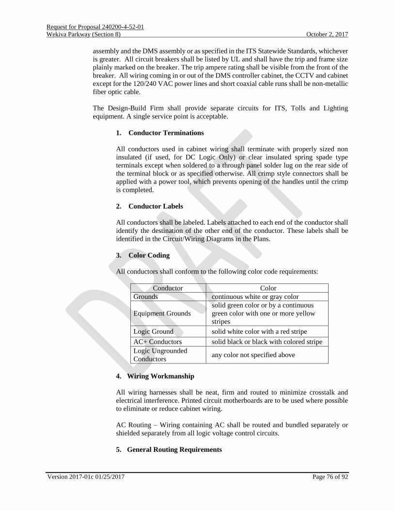
Request for Proposal 240200-4-52-01
Wekiva Parkway (Section 8) October 2, 2017
Version 2017-01c 01/25/2017 Page 76 of 92
assembly and the DMS assembly or as specified in the ITS Statewide Standards, whichever
is greater. All circuit breakers shall be listed by UL and shall have the trip and frame size
plainly marked on the breaker. The trip ampere rating shall be visible from the front of the
breaker. All wiring coming in or out of the DMS controller cabinet, the CCTV and cabinet
except for the 120/240 VAC power lines and short coaxial cable runs shall be non-metallic
fiber optic cable.
The Design-Build Firm shall provide separate circuits for ITS, Tolls and Lighting
equipment. A single service point is acceptable.
1. Conductor Terminations
All conductors used in cabinet wiring shall terminate with properly sized non
insulated (if used, for DC Logic Only) or clear insulated spring spade type
terminals except when soldered to a through panel solder lug on the rear side of
the terminal block or as specified otherwise. All crimp style connectors shall be
applied with a power tool, which prevents opening of the handles until the crimp
is completed.
2. Conductor Labels
All conductors shall be labeled. Labels attached to each end of the conductor shall
identify the destination of the other end of the conductor. These labels shall be
identified in the Circuit/Wiring Diagrams in the Plans.
3. Color Coding
All conductors shall conform to the following color code requirements:
Conductor Color
Grounds continuous white or gray color
Equipment Grounds
solid green color or by a continuous
green color with one or more yellow
stripes
Logic Ground solid white color with a red stripe
AC+ Conductors solid black or black with colored stripe
Logic Ungrounded
Conductors any color not specified above
4. Wiring Workmanship
All wiring harnesses shall be neat, firm and routed to minimize crosstalk and
electrical interference. Printed circuit motherboards are to be used where possible
to eliminate or reduce cabinet wiring.
AC Routing – Wiring containing AC shall be routed and bundled separately or
shielded separately from all logic voltage control circuits.
5. General Routing Requirements

Request for Proposal 240200-4-52-01
Wekiva Parkway (Section 8) October 2, 2017
Version 2017-01c 01/25/2017 Page 77 of 92
Cabling shall be routed to prevent conductors from being in contact with metal
edges. Cabling shall be arranged so that any removable assembly may be removed
without disturbing conductors not associated with that assembly. Within the
cabinet, the DC logic ground and equipment ground shall be electrically isolated
from the AC grounded conductor and each other by 500 mega-ohms when tested
at 250 VDC, with the power line surge protector disconnected. AC Terminal Bus
The AC- copper terminal bus shall not be grounded to the cabinet or connected to
logic ground. Nylon screw with a minimum diameter of 0.25 inch shall be used for
securing the bus to the service panel. Cabinet Power Supply The cabinet power
supply DC Ground shall be connected to the DC logic ground bus using a No. 14
or larger stranded copper wire.
Each detector lead in pair, from the field terminals in the cabinet to the sensor unit
rack connector, shall be a cable of UL Type 2092 or better. The stranded tinned
copper drain wire shall be connected to a terminal on the input file terminal block.
This input terminal shall be connected to the equipment grounding bus through a
single conductor. Each detector lead in cable shall be labeled for the corresponding
lane that it is connected to.
6. Barrier Type Terminal Blocks
The terminal blocks shall be barrier type rated at 20 amperes, 600 volts RMS
minimum. The terminal screws shall be 0.3125 inch minimum length nickel plated
brass binder head type with screw inserts of same material. Screw size is called out
under associated cabinet assembly, file or side panel.
7. AC Terminals
The terminals of the power line service terminal block shall be labeled "L1" and
"AC ", and shall be covered with a clear insulating material to prevent inadvertent
contact. Terminating lugs large enough to accommodate No. 2 conductors shall be
furnished for the service terminal block. The terminal block shall be rated for 50
amperes at 600 volts peak, minimum. The block shall be either a double row, 3
position screw/insert with shorting bar (screws, inserts and shorting bars shall be
nickel plated brass) or a Marathon #1423552 (or approved equal). If the Marathon
block is used, the surge protectors shall be terminated under a screw head (not
common with AC+, AC or Equipment Ground). The AC+, AC and Equipment
Ground conductors connecting to the service terminals and appropriate busses
shall not be spade lugged.
i. Camera (CCTV)
CCTV cameras shall be HD (1080p). CCTV cameras shall have an embedded encoder. CCTV
cameras shall support 3 different feeds simultaneously: two multicast stream initiated by RSTP and
one unicast stream. The two multicast stream shall supply different frame rates as resolutions as
configured by the Department. CCTV cameras shall PTZ unless otherwise stated.
CCTV on SR 417 from Seminole Towne Center Blvd to project end shall be Axis CCTV in
accordance with the Proprietary Product Certification, Appendix Q of this RFP.

Request for Proposal 240200-4-52-01
Wekiva Parkway (Section 8) October 2, 2017
Version 2017-01c 01/25/2017 Page 78 of 92
i. Verification CCTV
Verification CCTV Cameras may be static.
ii. Digital Video Encoders
No external digital video encoders are permitted for newly installed CCTV.
j. Microwave Vehicle Detection System (MVDS)
MVDS including concrete poles and mountings shall be installed to detect all general purpose,
express lanes and all entrance and exit ramps along the project corridor. MVDS shall not be placed
within 1000 feet of a toll plaza building or toll gantry structure. All MVDS shall be communicate
via Ethernet switch and no master/slave communication design will be allowed unless coincident
along the centerline of the project. MVDS shall be Wavetronix HD in accordance with the
Proprietary Product Certification, Appendix Q.
k. Dynamic Message Sign (DMS)
i. LCDMS
LCS shall be subject to the DMS Specifications in addition to the requirements provided
herein and in the Conceptual Plans. Each LCS shall be a minimum 4 feet square front-
access assembly.
The LCS displays shall be full color, full matrix with evenly spaced pixels, both vertically
and horizontally nominally providing a maximum 20mm pixel pitch. t Each LCS shall be
capable of displaying lane control designations, including green down arrow, red “X”, and
yellow arrow angled downward spanning the full height of the LCDMS.
The cabling shall have a minimum six (6) feet of slack and mounting hardware shall be
adjustable, such that moving the unit along the structure for future lane shifts is possible.
Each LCS shall have an individual controller and circuit breaker that shall be installed on
the ground in the equipment cabinet and not overhead within the LCS assembly. The LCS
controller software shall be compatible with FDOT’s SunGuide software.
ii. LSDMS
LSDMS shall be subject to the DMS Specifications in addition to the requirements
provided herein and in the Conceptual Plans. Each LSDMS shall be a one line DMS and
shall be the same width as the static sign it is below.
The LSDMS displays shall be full color, full matrix with evenly spaced pixels, both
vertically and horizontally nominally providing a maximum 20 mm pixel pitch for width
of eighteen characters.
The cabling shall have a minimum six (6) feet of slack and mounting hardware shall be
adjustable, such that moving the unit along the structure for future lane shifts is possible.
All slack cabling shall be dressed appropriately to insure it is not damaged during future
moves and other adjustments.
Each LSDMS shall have an individual controller and circuit breaker that shall be installed

Request for Proposal 240200-4-52-01
Wekiva Parkway (Section 8) October 2, 2017
Version 2017-01c 01/25/2017 Page 79 of 92
on the ground in the equipment cabinet and not overhead within the LSDMS assembly.
The LSDMS controller software shall be compatible with FDOT’s SunGuide software.
iii. EDMS
Each EDMS shall be subject to the DMS Specifications in addition to the requirements
provided herein and in the Conceptual Plans. The Static Signs and support structures shall
be designed to accommodate three (3) EDMS per static sign.
The EDMS displays shall be full color, full matrix with evenly spaced pixels, both
vertically and horizontally nominally providing a maximum 20mm pixel pitch for width
of seven characters
The cabling shall have a minimum six (6) feet of slack and mounting hardware shall be
adjustable, such that moving the unit along the structure for future lane shifts is possible.
Each EDMS shall have an individual controller and circuit breaker that shall be installed
on the ground in the equipment cabinet and not overhead within the EDMS assembly. The
EDMS controller software shall be compatible with FDOT’s SunGuide software.
iv. DMS
The sign shall be a full matrix, 20mm pixel density, full color, walk-in type display
enclosure. Each DMS shall have an individual controller and circuit breaker that shall be
installed on the ground in the equipment cabinet and not overhead within the DMS
assembly. The DMS controller software shall be compatible with FDOT’s SunGuide
software. The signs shall be placed in accordance with the Conceptual Plans.
l. Automated Vehicle Identification – Bluetooth (AVI)
BlueTOAD Bluetooth devices in accordance with the Proprietary Product Certification, Appendix
Q of this RFP, shall be placed on the Northbound and Southbound approaches east of Seminole
Towne Center Blvd and shall be connected to the adjacent local hub cabinet. All AVI shall be
communicate via Ethernet switch and no master/slave communication design will be allowed.
m. Existing ITS Shelter
There is an existing ITS shelter southeast of Seminole Towne Center Blvd and SR 417. This
structure is not to be relocated or impacted. A minimum of 48” of access shall be provided
around the facility as measured from the drip line at all times.
4. Integration:
a. Devices Integrated into D5 ITS
The Design-Build Firm shall perform ITS device integrations and testing based on the
construction project milestones in accordance with the Contract Documents. All test equipment
used will have valid calibration certifications in accordance with the manufacturer’s
recommendations, notwithstanding modification required for integration. The Department’s
active and tested ITS device configuration settings, firmware versions, and SunGuide
configurations are provided on: www.cflsmartroads.com. The Design-Build Firm shall provide to
the Department all devices requiring integration 60 days prior to field implementation for the

Request for Proposal 240200-4-52-01
Wekiva Parkway (Section 8) October 2, 2017
Version 2017-01c 01/25/2017 Page 80 of 92
Department to review compatibility with SunGuide. If the device has posted configuration
settings, firmware versions, and SunGuide configurations on www.cflsmartroads.com and the
device is to be integrated with this firmware then the 60 day requirement will be waived.
The Design-Build Firm shall provide a Physical and Logical Topology to the Department for
concurrence in accordance with Section VI.R.2.a. Both integration topologies are to include all
LHES and Master hub switches within the project limits. The Design-Build Firm shall then setup
an Integration Meeting with the District 5 ITS network department, allowing a minimum of 2
weeks’ notice and review time of the physical and logical topologies. The Design-Build Firm is
responsible to provide all required information at the meeting. In the event the information is
incomplete or inaccurate the meeting will be rescheduled with corrected information. Integration
cannot proceed until a minimum of 14 calendar has elapsed following the complete and accurate
submittal of required documents at a pre-integration meeting. At the Integration Meeting the
Department will provide a basic network design for the network implementation and any
deviation from that plan requires Department review and approval prior to its execution. The
basic network plan includes IP Scheme, Standard Port Utilization for all LHES Devices
(including which ports are to be disabled), VLAN Tagging Scheme (if applicable), Universal
Naming Convention (UNC) to be configured on the devices, cabinet labeling standard, and
information on all Layer II and higher protocols to be run on the switches.
It is the Design-Build Firms’ responsibility to configure all devices in compliance with the
network plan and to verify device communication, network stability and redundancy prior to
connecting to the department network. Once the project network has been tested and approved
the project network may be connected to the Departments’ network, but only under direct
Department supervision. Once completed the Design-Build Firm shall then contact the
Department for configuring the management software (currently SunGuide) to control the
devices. The Design-Build Firm shall supply the Department with digital copies of the completed
traceability matrices and all other information required to configure the central control software.
The Design-Build Firm shall allow 2-4 weeks for the Department to enter the information into the
management software. The Design-Build Firm shall troubleshoot with the Department’s
assistance any issues that arise from configuring the network and the central control software.
Once the local devices have been configured in SunGuide, then remote testing may commence to
confirm remote connectivity to the RTMC. The Design-Build Firm shall provide any assistance
necessary to provide the Department with IP addresses, port status (tag, if any device is plugged
into a port, if so what device), and auto negotiation speeds for all switches that cannot be acquired
from the remote location.
Inability of the Department to access the information from the RTMC will constitute failing the
test. If the inspection is failed the Design-Build Firm shall reconfigure the necessary devices and
again work with the Department to get the devices into the central management software. After
this is complete the configurations shall again be tested. Failure will result in a repeating the
earlier step until the integration inspection is successfully completed.
Once the test is completed the Design-Build Firm shall start placing all Layer 3 configurations on
the switch, but only while under the supervision of District 5 ITS. Under no circumstance shall
the Design-Build Firm place anything greater than a Layer 2 configuration on the switch without
District 5 ITS supervision. Once all configurations are in place the Design-Build Firm shall
verify their functionality under District 5 ITS guidelines.

Request for Proposal 240200-4-52-01
Wekiva Parkway (Section 8) October 2, 2017
Version 2017-01c 01/25/2017 Page 81 of 92
b. Devices Integrated into FTE ITS
c. General Testing
Testing documents may be found in Appendix T of this RFP.
d. Device Sub-System Acceptance Testing (S-SAT)
All ITS devices shall be subject to a Sub-Systems Acceptance Test (S-SAT) to demonstrate and
document device operability from the nearest Department Master Hub via an Ethernet connection
to the full Layer 3 network switch. Perform all S-SAT tests and record all S-SAT results using the
Department approved testing procedures Exhibit B. S-SAT tests are to be scheduled and
performed for each ITS device sub-system (CCTV, VDS, etc.) after successful completion of the
Field Acceptance Test (FAT) for that sub-system, and after successful integration to the network.
At a minimum S-SAT test shall be performed for the following ITS device sub-systems: Local
Hub, Ethernet Switch (LHES), Uninterruptable Power Supply, Device Server, Closed Circuit
Television (CCTV), Automated Vehicle Identification (AVI), and Vehicle Detection System
(VDS).
e. ITS Device System Acceptance Testing (SAT)
Subject all ITS devices to a Systems Acceptance Test (SAT) to demonstrate and document device
operability from the SunGuide® Software and/or Regional Traffic Management Center (RTMC)
workstation. Perform all SAT tests and record all SAT results using the Department approved
testing procedures included in Exhibit C. SAT tests are to be scheduled and performed for each
ITS device sub-system (CCTV, VDS, etc.) after successful completion of the FAT and S-SAT for
that sub system. At a minimum SAT test shall be performed for the following ITS device sub-
systems: Local Hub Ethernet Switch (LHES), Uninterruptable Power Supply, Device Server,
Closed Circuit Television (CCTV), and Vehicle Detection System (VDS). The SAT shall exhibit
full functionality of the ITS deployment in the SunGuide® software.
f. 30-Day Operational Test Period [Burn-In]
After successful completion of all required FAT, S-SAT, and SAT tests for all sub-systems, all
ITS Devices shall be subject to a 30-Calendar Day Operational Test Period (OTP), during which
time the Contractor shall perform any and all maintenance required to maintain a fully functional
ITS system. The D/B Firm shall notify the Department in writing of the scheduled start date of
the OTP 14 calendar days prior to the commencement of the OTP. The OTP shall not be
performed without prior written approval from the Department. The 30-Day OTP shall consist of
the monitoring of all ITS devices and ancillary components to ensure continuous operation
without failure of any sub-system, ITS device, or ancillary component.
In the event of a sub-system, ITS device, or ancillary component failure causing a System
Shutdown, the OTP Test shall be terminated for purposes of testing and correcting identified
deficiencies causing the System Shutdown. System Shutdown is defined as any condition which,
due to work performed by the Contractor and/or its designee, results in the ITS device or ancillary
component thereof to cease operation.
For each period of System Shutdown, and after the identified deficiency has been corrected and

Request for Proposal 240200-4-52-01
Wekiva Parkway (Section 8) October 2, 2017
Version 2017-01c 01/25/2017 Page 82 of 92
met all applicable tests, the OTP shall be restarted for a new 30 consecutive calendar days starting
upon confirmation the deficiency is resolved. If the total number of System Shutdowns exceeds
three due to the same sub-system, ITS device, or ancillary component, the Contractor shall
remove and replace the sub-system, ITS device or ancillary component with a new and unused
unit subjecting it to all required tests including the FAT, S-SAT, and SAT. Upon written approval
from the department, the restart the 30-day OTP will begin.
The OTP steps described herein shall be repeated as many times as deemed necessary by the
Department to satisfy the requirements of these Technical Special Provisions. The Contractor
shall not be granted time extensions to perform the OTP due to any failures as described herein.
Correct any and all failures required to resume the OTP at no additional cost to the Department.
In the event a problem is discovered for which it is uncertain whether the cause is hardware or
software related, the 30 calendar-day OTP shall restart and repeat, unless otherwise directed by
the Department. However, the OTP shall not be deemed to have been successfully completed
until the problem has been corrected.
All software required for diagnosing malfunctions of hardware and software/firmware shall be
supplied by the Contractor and approved by the Department prior to use. A copy of all diagnostic
software shall be submitted to the Department with full documentation within 14 days of
deficiency resolution. Submit Failure Report Logs in demonstration that error rates are within
requirements set herein
5. Existing Conditions
Existing ITS records are included as Reference 31 of this RFP.
6. Maintenance
If the Design-Build Firm causes damage to the Department infrastructure they shall report the damage
immediately to the Department. The Department also may become aware of an issue via a number of
sources including but not limited to operator observation, Design-Build Firm personnel, FDOT
maintenance personnel, Florida Highway Patrol, citizen reports, etc. The Design-Build Firm shall assist as
necessary in the diagnosis of the cause of an issue.
The work shall not include repairs or replacements made necessary by defects resulting from a third party;
vandalism, traffic accidents, or acts of God. In the event, that such repair or replacement is necessary, the
FDOT's Project Representative reserves the right to negotiate with the Design-Build Firm for such repair
or replacement or reserves the right to use the current FDOT maintenance contractor to rectify the third
party damage.
Failure of existing and/or proposed system or subsystem components/software to perform:
Components/software that fails to operate in the manner described in the Plans, this RFP and the ITS
Statewide Specifications, shall be replaced by the Design-Build Firm at Design-Build Firm’s expense
with components/software that meet the requirements of the Plans, this RFP, and the Technical ITS
Statewide Specifications. The FDOT's Project Representative shall make the sole determination of
whether or not a given system/subsystem has failed to perform.
The Design-Build Firm shall maintain a log of all response maintenance and repair activities performed
during the Burn-in period by the Design-Build Firm. The log shall be kept in a database management

Request for Proposal 240200-4-52-01
Wekiva Parkway (Section 8) October 2, 2017
Version 2017-01c 01/25/2017 Page 83 of 92
system utilizing FDOT-approved database software, and include, as a minimum, the following
information:
• Date and time defect reported
• Entity reporting the defect
• Description of the reported defect
• Arrival time at the site of the reported defect
• Technician performing defect repair or replacement
• Corrective actions taken
• Model and serial number of any component repaired or replaced
• Date and time defect rectified.
If the Design-Build Firm fails to perform any maintenance within the time frame for component-related
defects or central system defects, the FDOT shall either perform the corrective work itself or contract
with a third party to perform the necessary corrective work. Corrective work necessary due to non-
performance by the Design-Build Firm shall be deducted from any payments due the Design-Build Firm.
Consistent non-performance on the part of the Design-Build Firm shall result in attachment of the
supplemental performance bond.
FDOT or FDOT representative’s performance of corrective work under this provision shall have no effect
on the Design-Build Firm’s warranty obligations.
7. Inventory Database/Facilities Management System
The Department is using the ITS Facility Management (ITSFM) system to enable the long-term ITS asset
and configuration management needs of the ITS Program statewide. The ITSFM compiles System asset
information in a single, web-accessible repository, allowing the Department to collectively manage the
entire system in a coordinated manner. The ITSFM is provided by the Central Office to the Districts and
other regional partners.
The Department has developed ITSFM data collection forms, custom GPS mapping configuration, data
dictionary and export routines, and feature import template tools designed to both standardize and
simplify the data collection process. These tools are available to contractors and consultants for use in
preparing as-built deliverables. These tools are synchronized with the ITSFM database and can be found
on the Department’s web site: http://fdot.gov/traffic/itsfm/
The Contractor is responsible for the completeness, accuracy and quality of the as-built deliverables. The
Contractor shall maintain records of the ITS installation in accordance with CPAM, the project’s Quality
Assurance (QA) Program, Standard Specifications Section 611, “Acceptance Procedures for Traffic
Control Signals and Devices,” and the Department’s website.
As-built deliverables shall be tested to verify that they meet the positional accuracy and minimum content
completeness defined in the latest version of the “ITSFM Functional Requirements” adopted by the
Department. A copy of this document is contained in Appendix P of this RFP.
The Intelligent Transportation System Facility Management (ITSFM) system shall be created as part of
the project as-built deliverables package. The Design-Build firm shall include the costs associated with
the collection of all the required ITSFM data. The Department will enter the data into the ITSFM central
database.

Request for Proposal 240200-4-52-01
Wekiva Parkway (Section 8) October 2, 2017
Version 2017-01c 01/25/2017 Page 84 of 92
The Department maintains an online Web page for the ITSFM system. The Design-Build firm shall find
and download the necessary ITSFM attribute forms, including samples. The ITSFM website URL is:
http://fdot.gov/traffic/itsfm/
The Design-Build Firm shall use two ITSFM data collection methods that complement each other in
producing the final complete database inventorying of the new ITS system. These data collection methods
are the electronic collection of data with a handheld GPS unit and the data to be entered in the ITS
attribute forms available in the Department ITSFM web site listed above.
The Department will only provide the following items associated with the completion of the ITSFM
project deliverable. These are computer based ITSFM training and data entry of the ITSFM data collected
by the Design-Build Firm into the ITSFM central database.
a. ITSFM Attribute forms:
The Design-Build Firm shall download the necessary ITSFM attribute forms that are
applicable to the ITS subsystems provided under this project. The internet address or
URL for these forms is http://fdot.gov/traffic/itsfm/. The Design-Build Firm shall
complete these forms in addition to the data collected electronically in the field with the
handheld GPS unit, or units. These forms complement the electronic data collected in the
handheld GPS units. The Design-Build Firm shall submit to the Department a list, for
review and approval, containing the ITSFM Attribute Forms that shall be used for the
completion of this As-Built deliverable.
b. ITSFM Required Fields
The Design-Build firm shall refer to Appendix P of this RFP for the requirements and
attribute forms required for the completion of the ITS inventory.
8. Training
No training is required as part of this project.
9. Spare Parts
Spare parts required as part of this project include the following
One (1) Lane Control Sign Assembly
10. Traffic Monitoring Site (TTMS)
The Design-Build Firm shall provide a Traffic Monitoring Site (TTMS) between begin project limits and
Station 1116+00 (covering each direction of Wekiva Parkway (SR 429)) according to Department
Standard Indices and Specifications provided in Appendix C of this RFP. The location chosen by the
Design-Build Firm shall ensure no conflict of the TTMS site loops and the adjacent Tolling Site loops.
The cabinet shall be located on the NB/SB roadside as depicted in the Standard Index.
S. Landscape Opportunity Plans:
It is the intent of this work item to preserve the opportunity to provide for significant landscape planting
areas within the Project limits that meet the intent of FDOT Highway Beautification Policy. The landscape

Request for Proposal 240200-4-52-01
Wekiva Parkway (Section 8) October 2, 2017
Version 2017-01c 01/25/2017 Page 85 of 92
opportunity design shall adhere to the FDOT Highway Beautification Policy with the intent of creating a
unified landscape theme for the project.
The Design-Build Firm shall provide the necessary site inventory and site analysis and shall prepare a
“Landscape Opportunity Plan” (Opportunity Plan) as part of the roadway plan set. The Landscape
Opportunity Plan shall consider the Design-Build Firm’s proposed roadway improvements, utilities,
setbacks and clear zone dimensions, community commitments and other Project needs in identifying future
landscape planting areas. Landscape opportunity areas should be preserved in accordance with the
Departments “Bold” initiative.
The Opportunity Plans shall include the following:
1. Proposed improvements and existing elements to remain as associated with the Project.
2. Vegetation disposition depicting existing plant material to be removed, relocated or to
remain.
3. Wetland jurisdictional lines.
4. Proposed drainage retention areas and easements.
5. Proposed utilities and existing utilities to remain.
6. Graphically depicted on-site and off-site desired or objectionable views.
7. Locations of landscape opportunity planting areas in a bubble format which identifies
various vegetation groupings in a hatched or colorized manner. Examples are:
“trees/palms/shrubs”, “shrubs only”, “buffer plantings”, etc.
8. Provided and labeled applicable clear zone, horizontal clearance, setback dimensions on
the plans and in chart form which reflect AASHTO, FDOT and Department guidelines for
landscape installation and maintenance operations, including those that have been
coordinated with other disciplines
9. Identified outdoor advertising locations, owners and contacts and shown 1000 ft. view
zone.
10. Indicated potential area(s) for wildflower plantings.
The Opportunity Plan shall match the scale and format used for the proposed roadway sheets. Should this
format not convey design intent that is clearly legible, an alternate format may be considered.
Landscape construction documents and landscape installation are not included in this contract and shall be
provided by others.
Disciplines that will have greatest impact to preserving landscape opportunities include environmental,
drainage, utilities, signing, lighting and ITS. The DBLA shall identify potential conflicts relating to
preserving opportunity landscape areas and provide suggested resolutions to preserve them. If conflicts
cannot be resolved by the Design-Build Firm and the DBLA, they shall be discussed with the Department’s
Project Manager and District Landscape Architect for coordination and resolution.
The DBLA shall research and confirm any legally permitted outdoor advertising billboard (ODA) within
1,000-feet of the Project limits. The ODA sign(s) and 1,000-feet maximum vegetation protection zone limit
shall be indicated on the plans. The Design-Build Firm’s Landscape Architect shall provide a copy of all
correspondence and attachments to the Department’s District Landscape Architect.
The DBLA shall conduct a visual survey of existing vegetation within and adjacent to the Right of Way of
the project. General locations of existing vegetation that will remain after roadway and associated

Request for Proposal 240200-4-52-01
Wekiva Parkway (Section 8) October 2, 2017
Version 2017-01c 01/25/2017 Page 86 of 92
improvements are completed shall be shown with notations of general plant species in each location on the
Opportunity Plan. The DBLA shall identify proposed buffer areas as needed.
The DBLA shall meet with the District Landscape Architect prior to the beginning of work for the purposes
of coordination and to discuss adherence to the Highway Beautification Policy. No proposed planting areas
indicated on the Opportunity Plan can occur in: federal and/or state jurisdictional wetlands or other surface
waters; within open water bodies; in the bottom of stormwater management facilities; or use obligate
wetlands or facultative wetland species within 25 feet of the seasonal high water of wetlands or other surface
waters. Limited plantings may occur on the slopes and bottom of stormwater management facilities once
coordinated with the District EMO office, District Drainage Engineer and the District Landscape Architect.
Trees may not be planted within 5 feet of storm sewer pipes and utilities.
T. Tolling Requirements:
The Design-Build Firm shall furnish and install tolling infrastructure per the FTE GTR.
The table below is a complement to the FTE GTR and contains infrastructure types and quantities that shall
be furnished and installed by the Design-Build Firm.
Infrastructure Type & Quantity Tolling Point
Gantry Type Non-Accessible
Gantry Quantity 1
Pavement Type Asphalt
Building Type New
Building Quantity 1
E6 Reader Location On Gantry
Building Communication Type Fiber and Leased Circuit Digital Communication Lines
End to End Testing No
H-20 loading pull boxes are required as outlined in the FTE’s TPPPH manual.
The Design-Build Firm shall refer to the FTE GTR for design criteria and construction requirements for
complete and fully operational tolling point. Included with this requirement is providing full utility
connections to the toll site.
The tolling site location (Station 1119+00) is shown in Reference Document 2 - Concept Plans. The tolling
site location shall not change unless an ATC is submitted and approved by the Department.
The Design-Build Firm shall provide a building design meeting current building code requirements at the
time of permit application.
The Design-Build Firm shall obtain required building permits. Refer to the FTE GTR for building
permitting and fire marshal requirements.
The Design Build Firm shall have a single professional engineer, registered in the State of Florida, in
responsible charge of developing the plans and specifications for toll site electrical, building electrical and
gantry electrical.

Request for Proposal 240200-4-52-01
Wekiva Parkway (Section 8) October 2, 2017
Version 2017-01c 01/25/2017 Page 87 of 92
VII. Technical Proposal Requirements:
A. General:
Each Design-Build Firm being considered for this Project is required to submit a Technical Proposal. The
proposal shall include sufficient information to enable the Department to evaluate the capability of the
Design-Build Firm to provide the desired services. The data shall be significant to the Project and shall be
innovative, when appropriate, and practical.
B. Submittal Requirements:
The Technical Proposal shall be bound with the information, paper size and page limitation requirements
as listed herein.
A copy of the written Technical Proposal must also be submitted in PDF format including bookmarks for
each section on a CD, DVD, or Flash Drive. Bookmarks which provide links to content within the
Technical Proposal are allowed. Bookmarks which provide links to information not included within the
content of the Technical Proposal shall not be utilized. No macros will be allowed. Minimum font size of
ten (10) shall be used. Times New Roman shall be the required font type.
Only upon request by the Department, provide calculations, studies and/or research to support features
identified in the Technical Proposal. This only applies during the Technical Proposal Evaluation phase.
Submit 1 Original, four (4) CD’s, DVD’s or Flash Drives containing the Technical Proposal in PDF
format and seven (7) collated, complete sets of hard copies of the Technical Proposal to:
Ms. Michelle Sloan, Professional Services Administrator
Florida Department of Transportation
719 South Woodland Boulevard
De Land, FL 32720
The minimum information to be included:
Section 1: Project Approach
Paper size: 8½" x 11". The maximum number of pages shall be twelve (12),
single-sided, typed pages including text, graphics, tables, charts, and
photographs. Double-sided 8½" x 11" sheets will be counted as 2 pages.
11”x17” sheets are prohibited.
Describe how the proposed design solutions and construction means and
methods meet the project needs described in this Request for Proposal.
Provide sufficient information to convey a thorough knowledge and
understanding of the project and to provide confidence the design and
construction can be completed as proposed.
Provide the term, measurable standards, and remedial work plan for any
proposed Value Added features that are not Value Added features included in
this RFP, or for extending the Value Added period of a feature that is included
in this RFP. Describe any material requirements that are exceeded.
Provide a Written Schedule Narrative that describes the Design and
Construction phases and illustrates how each phase will be scheduled to meet

Request for Proposal 240200-4-52-01
Wekiva Parkway (Section 8) October 2, 2017
Version 2017-01c 01/25/2017 Page 88 of 92
the Project needs required of this Request for Proposal. Bar or Gantt charts
are prohibited.
Section 2: Plans and Technical Special Provisions
Plan and Profile views of the proposed improvements shall be submitted
in roll-plot format. The maximum width of the roll-plots shall be 36”.
The maximum length of the roll-plot shall be 8’. Inclusion of additional
information on the roll-plot, other than depictions of the Plan and Profile
views, is allowed provided it clarifies the plan and profile views.
However, the Department may determine that such additional
information is excessive and may require the Design-Build Firm to
revise and resubmit the roll-plots. If this occurs, the Design-Build Firm
will have 2 business days to revise and resubmit the roll-plots upon
notification by the Department. All other information not included on
the roll plots, such as typical sections, special emphasis details, structure
plans, etc., shall be provided on 11”x17” sheets.
Provide Landscape Opportunity Plan sheets that depict a Bold Landscape
design for the entire project limits. The Landscape Plan shall include graphic
plant symbols that show the plant location, plant type, plant quantity, plant
botanical and common name and installed plant size. Paper size shall be
11”x17”.
Right of Way Maps and Legal Descriptions (including area in square feet) of
any proposed additional Right of Way parcels if applicable and approved
through the ATC process. Provide Technical Proposal Plans in accordance
with the requirements of the Plans Preparation Manual, except as modified
herein.
Demonstrate how the SR 429 mainline and I-4 mainline bridges will
accommodate the ultimate configuration.
Technical proposals shall comply with GTR for Toll Facility requirements.
The Plans shall complement the Project Approach.
C. Evaluation Criteria:
The Department shall evaluate the written Technical Proposal by each Design-Build Firm. The Design-
Build Firm should not discuss or reveal elements of the price proposal in the written proposals. A technical
score for each Design-Build Firm will be based on the following criteria:
Item
Value
1.
2.
3.
4.
Design
Construction
Innovation
Value Added
40
30
5
5
Maximum Score
80
The following is a description of each of the above referenced items:

Request for Proposal 240200-4-52-01
Wekiva Parkway (Section 8) October 2, 2017
Version 2017-01c 01/25/2017 Page 89 of 92
1. Design (40 points)
Credit will be given for the quality and suitability of the following elements:
Structures design
Roadway design / and safety
Drainage design
Environmental Design
Design coordination plan minimizing design changes
Geotechnical investigation plan
Geotechnical load test program
Minimizing impacts through design to:
o Environment
o Public
o Adjacent Properties
o Structures
Traffic Control Plan design
Incident Management Plan
Aesthetics
Utility Coordination and Design
Design considerations which improve recycling and reuse opportunities
Credit will be given for aesthetics features of the design including but not limited to the following:
considerations in the geometry, suitability and consistency of structure type, structure finishes, shapes,
proportions and form throughout the limits of the project.
Architectural treatments such as tiles, colors, emblems, etc. will not be considered as primary aesthetic
treatments.
Credit will be given for design and utility coordination efforts that minimize the potential for adverse
impacts and project delays due to utility involvement.
Credit will be given for development of design approaches which minimize periodic and routine
maintenance. The following elements should be considered: access to provide adequate inspections and
maintenance, access to structure’s lighting system, and impacts to long term maintenance costs.
2. Construction (30 points)
Credit will be given for the quality and suitability of the following elements:
Safety
Structures construction
Roadway construction
Drainage construction
Construction coordination plan minimizing construction changes
Minimizing impacts through construction to:
o Environment
o Public
o Adjacent Properties
o Structures

Request for Proposal 240200-4-52-01
Wekiva Parkway (Section 8) October 2, 2017
Version 2017-01c 01/25/2017 Page 90 of 92
Implementation of the Environmental design and Erosion/Sediment Control
Plan
Implementation of the Maintenance of Traffic Plan
Implementation of the Incident Management Plan
Utility Coordination and Construction
Credit will be given for developing and deploying construction techniques that enhance project durability,
reduce long term and routine maintenance, and those techniques which enhance public and worker safety.
This shall include, but not be limited to, minimization of lane and driveway closures, lane widths, visual
obstructions, construction sequencing, and drastic reductions in speed limits.
Credit will be given for insuring all environmental commitments are honored.
Credit will be given for construction and utility coordination efforts that minimize the potential for adverse
impacts and project delays due to utility conflicts.
3. Innovation (5 points)
Credit will be given for introducing and implementing innovative design approaches and construction
techniques which address the following elements:
Minimize or eliminate Utility relocations
Materials
Workmanship
Enhance Design and Construction aspects related to future expansion of the
transportation facility
I-4 bridge over Ramp EE4
4. Value Added (5 points)
Credit will be given for the following Value Added features:
Broadening the extent of the Value Added features of this RFP while
maintaining existing threshold requirements
Exceeding minimum material requirements to enhance durability of project
components
Providing additional Value Added project features proposed by the Design-
Build Firm
The following Value Added features have been identified by the Department as being applicable to this
project. The Design-Build Firm may propose to broaden the extent of these Value Added features.
Value Added Feature Minimum Value Added Period
Value Added Asphalt 3 years
Value Added Concrete Pavement 5 years
Value Added Bridge Components 5 years

Request for Proposal 240200-4-52-01
Wekiva Parkway (Section 8) October 2, 2017
Version 2017-01c 01/25/2017 Page 91 of 92
D. Final Selection Formula:
The Department shall publicly open the sealed bid proposals and calculate an adjusted score using the
following formula:
TS
BPP = Adjusted Score
BPP = Bid Price Proposal
TS = Technical Score (Combined Scores from LOI and Technical Proposal)
The Design-Build Firm selected will be the Design-Build Firm whose adjusted score is lowest.
The Department reserves the right to consider any proposal as non-responsive if any part of the Technical
Proposal does not meet established codes and criteria. If the Proposed Contract Time is greater than the
Maximum Contract Time of 1,400 calendar days, the Bid Price Proposal will be considered non-responsive.
E. Final Selection Process:
After the sealed bids are received, the Department will have a public meeting for the announcement of the
Technical Scores and opening of sealed Bid Price Proposals. This meeting will be recorded. At this meeting,
the Department will announce the score for each member of the Technical Review Committee, by category,
for each Proposer and each Proposer’s Technical Score. Following announcement of the Technical Scores,
the sealed Bid Price Proposals will be opened and the adjusted scores calculated. The Selection Committee
should meet a minimum of two (2) calendar days (excluding weekends and Department observed holidays)
after the public opening of the Technical Scores and Bid Price Proposals. The Department’s Selection
Committee will review the evaluation of the Technical Review Committee and the Bid Price Proposal of
each Proposer as to the apparent lowest adjusted score and make a final determination of the lowest adjusted
score. The Selection Committee has the right to correct any errors in the evaluation and selection process
that may have been made. The Department is not obligated to award the contract and the Selection
Committee may decide to reject all proposals. If the Selection Committee decides not to reject all proposals,
the contract will be awarded to the Proposer determined by the Selection Committee to have the lowest
adjusted score.
F. Stipend Awards:
The Department has elected to pay a stipend to a limited number of non-selected Short-Listed Design-Build
Firms to offset some of the costs of preparing the Proposals. The non-selected Short-Listed Design-Build
Firms meeting the stipend eligibility requirements of the Project Advertisement and complying with the
requirements contained in this section will ultimately be compensated. The stipend will only be payable
under the terms and conditions of the Design-Build Stipend Agreement and Project Advertisement, copies
of which are included with this Request for Proposal. This Request for Proposal does not commit the
Department or any other public agency to pay any costs incurred by an individual firm, partnership, or
corporation in the submission of Proposals except as set forth in the Design-Build Stipend Agreement. The
amount of the stipend will be $595,575.94 per non-selected Short-Listed Design-Build Firm that meets the
stipend eligibility requirements contained in the Project Advertisement. The stipend is not intended to
compensate any non-selected Short-Listed Design-Build Firm for the total cost of preparing the Technical
Request for Proposal 240200-4-52-01
Wekiva Parkway (Section 8) October 2, 2017
Version 2017-01c 01/25/2017 Page 92 of 92
and Price Proposals. The Department reserves the right, upon payment of stipend, to use any of the concepts
or ideas within the Technical Proposals, as the Department deems appropriate.
In order for a Short-Listed Design-Build Firm to remain eligible for a stipend, the Short-Listed Design-
Build Firm must fully execute with original signatures and have delivered to the Department within one
(1) week after the Short-List protest period, four (4) originals of the Design-Build Stipend Agreement, Form
No. 700-011-14. The Short-Listed Design-Build Firm shall reproduce the necessary copies. Terms of said
agreement are non-negotiable. A fully executed copy of the Design-Build Stipend Agreement will be
returned to the Short-Listed Design-Build Firm.
A non-selected Short-Listed Design-Build Firm eligible for stipend compensation must submit an invoice
for a lump sum payment of services after the selection/award process is complete. The invoice should
include a statement similar to the following: "All work necessary to prepare Technical Proposal and Price
Proposals in response to the Department's RFP for the subject Project".
VIII. Bid Proposal Requirements.
A. Bid Price Proposal:
Bid Price Proposals shall be submitted on the Bid Blank form attached hereto and shall include one lump
sum price for the Project and the number of calendar days within which the Proposer will complete the
Project. The lump sum price shall include all costs for all design, geotechnical surveys, architectural
services, engineering services, Design-Build Firms quality plan, construction of the Project, and all other
work necessary to fully and timely complete that portion of the Project in accordance with the Contract
Documents, as well as all job site and home office overhead, and profit, it being understood that payment
of that amount for that portion of the Project will be full, complete, and final compensation for the work
required to complete that portion of the Project. One (1) hard copy Bid Price Proposal shall be hand
delivered in a separate sealed package to the following:
Ms. Michelle Sloan, Professional Services Administrator
Florida Department of Transportation
719 South Woodland Boulevard
De Land, FL 32720
The package shall indicate clearly that it is the Bid Price Proposal and shall identify clearly the Proposer’s
name, contract number, project number, and Project description. The Bid Price Proposal shall be secured
and unopened until the date specified for opening of Bid Price Proposals.