republic of lebanon - procurement notices
TRANSCRIPT

Technical Specifications
July 2017
Design for Irrigation Channels in Mohammara
REPUBLIC OF LEBANON United Nations Development Programme

Design for Irrigation Networks in Mohammara Concrete Work - General
P-1712A
July 2017 Page 1 of 45
CONCRETE WORKS – General
TABLE OF CONTENTS
301 GENERAL ...................................................................................................................... 4 302 CONCRETE ................................................................................................................... 4
302.1 Requirements ........................................................................................................... 4 302.2 Strength .................................................................................................................... 6 302.3 Consistency and Slump ........................................................................................... 6 302.4 Mixes ....................................................................................................................... 6 302.5 Quality Control ........................................................................................................ 7 302.6 Production ................................................................................................................ 8 302.7 Ready Mixed Concrete ............................................................................................ 8 302.8 Cement ..................................................................................................................... 9 302.9 Aggregates ............................................................................................................... 9 302.10 Water .................................................................................................................. 10 302.11 Admixtures ......................................................................................................... 11
303 REINFORCEMENT ..................................................................................................... 11 303.1 Steel ....................................................................................................................... 11 303.2 Storage ................................................................................................................... 11 303.3 Bending and Fixing ............................................................................................... 11 303.4 Couplers ................................................................................................................. 12
304 FORMWORK ............................................................................................................... 13 304.1 Requirements ......................................................................................................... 13 304.2 Sawn Formwork .................................................................................................... 14 304.3 Wrought Formwork ............................................................................................... 14 304.4 Special Wrought Formwork .................................................................................. 14 304.5 Tolerances .............................................................................................................. 15 304.6 Striking and Removal ............................................................................................ 15
305 CONCRETING ............................................................................................................. 16 305.1 Requirements ......................................................................................................... 16 305.2 Transporting........................................................................................................... 16 305.3 Placing and Compaction ........................................................................................ 17 305.4 Concreting in Deep Lifts ....................................................................................... 17 305.5 Hot Weather Concreting (for Temperatures above 20ºC) ..................................... 17 305.6 Wet Weather Concreting ....................................................................................... 18 305.7 Holes, Cavities and Fixings ................................................................................... 18 305.8 Protection ............................................................................................................... 19
306 JOINTS ......................................................................................................................... 22 306.1 Construction Joints ................................................................................................ 22 306.2 The ‘’Wash-off Method’’ of Preparing Construction Joints ................................. 23 306.3 Contraction and Expansion Joints ......................................................................... 23 306.4 Water Stop ............................................................................................................. 23 306.5 Joint Filler .............................................................................................................. 24 306.6 Joint Sealants ......................................................................................................... 24

Design for Irrigation Networks in Mohammara Concrete Work - General
P-1712A
July 2017 Page 2 of 45
306.7 Slip Membrane ...................................................................................................... 25 306.8 Dowel Bars ............................................................................................................ 25 306.9 Bond Breaking Compound for Dowel Bars .......................................................... 26
307 FINISHES ..................................................................................................................... 26 307.1 Finishes – General ................................................................................................. 26 307.2 Surface Finishes ..................................................................................................... 26 307.3 Making Good ......................................................................................................... 27
308 DEFECTS ..................................................................................................................... 27 308.1 Removal and Replacement of Unsatisfactory Concrete ........................................ 27 308.2 Loading Tests ........................................................................................................ 27
309 TESTING ...................................................................................................................... 28 309.1 Sampling and Testing ............................................................................................ 28
310 SPECIAL CONCRETE ................................................................................................ 29 310.1 No-Fines Concrete ................................................................................................. 29 310.2 Air-Entrained Concrete.......................................................................................... 29 310.3 Concrete in Benching ............................................................................................ 29 310.4 Pneumatically Applied Mortar (Gunite) ................................................................ 29 310.5 Pumped Concrete ................................................................................................... 31
311 CONCRETE UNITS ..................................................................................................... 31 311.1 Requirements ......................................................................................................... 31 311.2 Concrete Manholes ................................................................................................ 31 311.2.1 Cast-In Situ Reinforced Concrete Manholes ..................................................... 32 311.2.2 Precast Concrete Manholes ................................................................................ 32 311.2.3 Manhole Benching, Plastering and Coating....................................................... 32 311.2.4 Drop Manhole .................................................................................................... 33 311.2.5 Manhole Cover and Grating ............................................................................... 33 311.2.6 Inlet and Outlet Joints ........................................................................................ 34 311.2.7 Manholes Inspection .......................................................................................... 34 311.3 Kerbs ...................................................................................................................... 35 311.3.1 Manufacturing & Construction .......................................................................... 35 311.3.2 Concrete Kerbs Painting .................................................................................... 36 311.4 Paving Slabs .......................................................................................................... 38 311.5 Other Blocks .......................................................................................................... 38
312 SITE BOOKS AND STANDARDS ............................................................................. 38 312.1 Instruction to be Recorded ..................................................................................... 38 312.2 Site Diary ............................................................................................................... 38
313 SLUICE GATES:.............................................................................................................. 41 313.1 Governing Standards .................................................................................................. 41 313.2 Manufacturer's Qualifications .................................................................................... 41 313.3 Materials .................................................................................................................... 41 313.4 Submittals .................................................................................................................. 42 313.5 Performance ............................................................................................................... 42 313.6 Sluice Gates ............................................................................................................... 42 313.7 Disc or Slide ............................................................................................................... 42 313.8 Frame ......................................................................................................................... 43 313.9 Wedges ....................................................................................................................... 43 313.10 Seat Facings ............................................................................................................. 43

Design for Irrigation Networks in Mohammara Concrete Work - General
P-1712A
July 2017 Page 3 of 45
313.11 Flush bottom Seal .................................................................................................... 43 313.12 Wall Thimble ........................................................................................................... 44 313.13 Stem ......................................................................................................................... 44 313.14 Stem Guides ............................................................................................................. 44 313.15 Self-Contained Sluice Gates .................................................................................... 44 313.16 Additional Optional Seals (Unseating Side Only) ................................................... 45 313.17 Manual Gates ........................................................................................................... 45 313.18 Painting .................................................................................................................... 45 313.19 Shop Testing ............................................................................................................ 45 313.20 Installation................................................................................................................ 45 313.21 Start-Up and Test ..................................................................................................... 45

Design for Irrigation Networks in Mohammara Concrete Work - General
P-1712A
July 2017 Page 4 of 45
CONCRETE WORKS – General 301 GENERAL
No material shall be used in the Works until prior approval for its use has been given by the Engineer, neither shall any change in the nature, quality, kind, type and source of supply of manufacture be made without the Engineer’s approval. Names of manufacturers and test certificates for materials not supplied by the Employer shall be supplied as soon as possible to the Engineer. The cost of providing samples and the cost of carrying out tests required by this specification (except as otherwise provided in the Conditions of Contract) together with the cost of supplying equipment for sampling and site testing shall be borne by the Contractor. During the progress of the Works, consignment notes for materials not supplied by the Employer shall be supplied to the Engineer giving details of each consignment.
302 CONCRETE 302.1 Requirements
The mix proportions shall be selected to ensure that the workability of the fresh concrete is suitable for the conditions of handling and placing, having regard to the structural element being constructed, the disposition of reinforcement, and taking full account of the environment to which it will be subjected. The minimum cement contents and maximum water/cement ratios of designed mixes shall be as given in Table 3.1. In the event of sulphate exposure precautions requiring lower cement content than those required for normal conditions the latter requirement shall prevail. The maximum cement content in any mix shall not exceed 500 kg/m3 for normal structures and 425 kg/m3 for liquid retaining structures. In all cases of mix proportioning, the added water shall be included with due allowance for the moisture contained in the aggregate and shall be the minimum consistent with the workability requirements.

Design for Irrigation Networks in Mohammara Concrete Work - General
P-1712A
July 2017 Page 5 of 45
Table 3.1:.Minimum Cement Contents Normal Conditions
Type of Structural
Element
Exposure Conditions
(BS EN 1992-1-1:2004)
Minimum Cement Content
(kg/m3)
Maximum
Water/ Cement
Ratio
Maximum Aggregate Size
40 mm 20 mm 10 mm Liquid Retaining
Structures, Shafts and Tunnel Linings
Severe 295 325 356 0.55
All Foundations and Buried Structures
Moderate 270 300 340 0.60
Building Super-Structure
Moderate 270 300 340 0.60
Additional Requirements When Exposed To Sulphate Conditions (All Structural Concrete):
Concentration of Sulphates
Type of Cement
Minimum Cement Content (kg/m3)
Maximum Aggregate Size
Maximum
Water/ Cement
Ratio In Soil (Total SO3)
In Ground Water Parts Per 100,000
40 mm 20 mm 10 mm
< 0.2 < 30 OPC NORMAL CONDITIONS 0.2 – 0.5 30 – 120 OPC
SRPC 300 250
330 280
370 320
0.50 0.55
0.5 – 1.0 120 – 250
OPC SRPC
Not Permitted 300
330
370
0.50
1.0 – 2.0 250 - 500 OPC SRPC
Not Permitted 340
370
410
0.45
> 2.0 >500 SRPC Ditto but with protective coating
0.45

Design for Irrigation Networks in Mohammara Concrete Work - General
P-1712A
July 2017 Page 6 of 45
302.2 Strength
The characteristic strength of concrete means that value of the 28 day cube (150mmx150mmx150mm) strength below which 5% of all possible test results would be expected to fall. Concrete is classified on the basis of its characteristic strength in compression at 28 days as shown in Table 3.2.
Table 3.2: Concrete Classification
Class of concrete
C10 C15 C20 C25 C30 C35 C40 Fine concrete
C25 Concrete
characteristic strength (MPa)
10
15
20
25
30
35
40
25
Maximum size of coarse
aggregate
20
20
20
20
20
20
20
10
302.3 Consistency and Slump
Concrete shall be of consistency and workability suitable for the conditions on the job. For most concrete a “plastic” mix is required, vibrated, without segregation.
Slump tests shall be performed to determine the consistency of concrete, and it shall be used and made in accordance with BS EN 12350-8:2010. The Contractor shall provide the equipment necessary to determine the slump of freshly-mixed concrete at each place where concrete is being placed and shall determine the slump of the concrete on each occasion that a set of test cubes is made and not less than once a day or as the Engineer may direct. Samples shall be taken before concrete placement and after emptying 50% -80% of the truck load. Concrete delivered for placing, except as otherwise instructed by the Engineer, shall have a working slump limit ranging from 75 to 125 mm. Whenever, the working slump limit is out of the range mentioned above, the concrete shall be rejected and disposed of at the Contractor’s expense. The Engineer may choose to adopt lesser slumps whenever concrete of such lesser slump can be poured and consolidated readily in place by means of vibrators.
302.4 Mixes Designed mixes
Proportions shall be determined in accordance with the ‘’Design of Normal Concrete Mixes’’ Published by the United Kingdom Department of The Environment and obtainable from:

Design for Irrigation Networks in Mohammara Concrete Work - General
P-1712A
July 2017 Page 7 of 45
- Building Research Establishment and Bookshop. - Garston. - Watford. - WD2 7JR. - ENGLAND.
Or other approved methods, which comply with the requirements set out in this Specification. For the purpose of determining the design mean strength of the concrete a margin shall be added to the characteristic strength for the particular grade of concrete. This design margin shall be assessed on the degree of control reasonably to be expected in the manufacture of the concrete and shall not be less than 7.5N/mm2 nor less than 1.64 times the standard deviation. Until such time as the standard deviation has been assessed the margin shall be not less than 15N/mm2. Details of the designed mixes shall be forwarded immediately to the Engineer for his approval. After completing the tests, the Contractor shall submit to the Engineer for approval the proportioning of mixtures to be adopted for the various structures. The Contractor shall be completely responsible for producing and maintaining quality of concrete with compressive strength not inferior to the specified one unless otherwise instructed by the Engineer. Chloride content The total chloride content of the concrete mix shall comply with the requirements of BS 1881 DD216:1993.
302.5 Quality Control
Compliance with the specified characteristic strength shall be based on tests on cubes at an age of 28 days. Sampling and testing of concrete shall comply with BS 1881-124:1988. For major structures the frequency of sampling shall be initially three samples taken each day for five days of concreting and thereafter at a frequency of one sample per 10m3 of concrete but not less than one sample for each day concreting. For mirror structures the frequency of sampling shall be one sample per 20m3 but not less than one sample for each day concreting. For mass concrete works and concrete works at pipeline appurtenances sampling shall be at an average of one sample per 50m3. A minimum of 3 test cubes shall be made from each sample. Where materials are of an unfamiliar grading or type, or where directed by the Engineer compression tests shall be carried out at 7 days and adjustment made in advance of the main control methods outlined above.
Design for Irrigation Networks in Mohammara Concrete Work - General
P-1712A
July 2017 Page 8 of 45
Cube test results will be examined individually in 10 consecutive sets of four and the standard deviation and mean strength of each set calculated. The concrete mix proportions will only be acceptable if all of the following requirements are complied with:
Not more than two results in 40 are less than the characteristic crushing strength.
No value of the average for any set of four results is less than the characteristic strength plus one-half of the design margins. When 40 results have been obtained and the mean strength and standard deviation are calculated, the mean strength minus 1.64 times the standard deviation shall be greater than the characteristic strength.
Where the results do not conform to the above requirements the following action shall be taken: - Adjustments to the mix shall be made to obtain the strength required. - In the case where any result is less than 80% of the characteristic strength the
structural implications shall be considered and action taken as ordered by the Engineer.
302.6 Production
Aggregates and cement shall be proportioned by weight-batching. Subject to the prior approval of the Engineer volume-batching may be used for small section of work, but volume batching of cement will in no case be accepted. The Contractor may, however, so proportion the mix that each batch shall use a whole bag or bags of cement, the weight of which is known precisely. All gauge boxes shall be accurate and due allowance shall be made for bulking of the aggregates in assessing the correct volume to be used. The aggregates and the cement shall be thoroughly mixed in a clean mechanical mixer for a period of time agreed with the Engineer and the water added on the basis of the approved design. The amount of water added shall conform to the requirements of Clause 302.1 Batch mixing machines shall comply with the requirement of BS 1305:1974. They shall be provided in such numbers and of such capacity as to ensure a continuous supply of freshly mixed concrete at all times during construction. Continuous mixing machines shall be used only upon the written permission of the Engineer.
302.7 Ready Mixed Concrete
Unless otherwise stated the relevant clauses of BS 8000-2.1:1990 shall apply. Ready mixed concrete shall only be used after the prior approval of the Engineer. The contractor shall not be relieved of his obligation to provide concrete to the

Design for Irrigation Networks in Mohammara Concrete Work - General
P-1712A
July 2017 Page 9 of 45
standard laid down in this Specification by virtue of any approval given for the use of concrete supplied by others, and the Engineer reserves the right to withdraw his approval at any time consequent on any deterioration in the quality of the concrete, or unsatisfactory delivery or any other reason he considered detrimental to the Works, Ready mixed concrete manufactured off the site shall be transported in a revolving drum and shall be continuously agitated until it is used in the work unless otherwise approved. The time interval between adding water to the drum and placing shall not exceed 90 minutes.
302.8 Cement
Cement shall comply with one of the following Sub-Clause (i) to (iv) below: (i) BS EN 197-1:2011 (Ordinary and rapid-hardening Portland cement), type CEM
I 42.5R (ii) BS EN 197-1:2011(Portland-blastfurnace cement) (iii) BS 4027 : 1996 (R07) (Sulphate resisting Portland cement), type P-Al 42.5 or
P=PMS 42.5 (iv) BS EN 197-1:2011 (Portland pulverized-fuel ash cement) provided that Sub-
Clause (vii) below is complied with.
Cement used for structures in contact with wastewater shall be sulphate resisting Portland Cement in accordance with BS 4027: 1996. Cement shall be fresh when delivered to Site and the consignments shall be used in the order of their delivery. The Contractor shall mark the date of delivery on each consignment and each consignment shall be stored separately and in such manner as to be easily accessible and identifiable. Cement in bags or other containers shall be intact at the time of mixing. Cement bags shall be stored in a waterproof building and be placed on dry boards above the floor to prevent deterioration or contamination from any cause. Bulk cement may be used provided it is stored in an approved container. Cement of different types shall be kept separate in storage and shall not be mixed together.
302.9 Aggregates
Fine and coarse aggregates shall be as defined by and be of the quality and nature required by BS EN 12620: 2002+A1:2008. In addition they shall be chemically inert to alkali reaction.

Design for Irrigation Networks in Mohammara Concrete Work - General
P-1712A
July 2017 Page 10 of 45
Prior to acceptance of an aggregate as inert to alkali reaction the report of a qualified geologist, appointed by the Contractor, on the suitability or otherwise of the aggregate shall be obtained. The Engineer may require that samples be taken from boreholes. Aggregates shall conform to the requirements of the ‘’Acceptance Standards’’ of table 3.6. The flakiness index of coarse aggregate in accordance with BS EN 933-3:2012 shall not exceed 35%. The Contractor shall ensure that the nature and grading of aggregates remain reasonably consistent, and half, if necessary, stockpile include different grading to ensure that the overall grading remains constant for each section of the work. Dust of flour resulting from crushing the aggregate shall not be allowed to contaminate the stockpiles. When, in the opinion of the Engineer such contamination has taken place it shall be removed by an approved means or the aggregate shall be rejected. The aggregates of various sizes shall be kept separate and away from all possible contamination, and shall be stored on a hard-standing area or in bins and provided with proper drainage at the base of the stockpiles. Except where aggregates have been otherwise specified on the Drawings the grading of aggregate shall be as follows: (i) Coarse Aggregate:
(a) 10mm max. size, graded, for all ‘’fine’’ concrete.
(b) 20mm max. size, graded, for all reinforced concrete, such as in beams and for walls and slabs.
(ii) Fine Aggregate:
(a) Where aggregates conforming to Zones 2 or 3 of BS EN,
12620:2002+A1:2008 are available they shall be used. 302.10 Water Water for use in concrete and in concreting operations shall be of potable quality:
Where required by the Engineer it shall be tested in accordance with BS EN 1008:2002 and if necessary shall be treated to assure compliance therewith. Water for washing and curing shall be such that it will impair neither the strength of the finished concrete nor its appearance.

Design for Irrigation Networks in Mohammara Concrete Work - General
P-1712A
July 2017 Page 11 of 45
302.11 Admixtures
Before approval for the use of a proprietary admixture is given the Contractor will be required to satisfy the Engineer as to its suitability for the work and its compatibility with the cement it is intended to complement and for the intended use of structure. Admixtures that contain chlorine shall not be used for potable water retaining structures.
303 REINFORCEMENT 303.1 Steel
Reinforcement shall be: a) Deformed high Yield steel bars conforming to BS 4449:2005+A2:2009.
Minimum yield point 420 MPa. b) Cold worked steel bars conforming to BS EN 4461:2007 or c) Fabric reinforcement made of cold drawn high tensile bars conforming to BS
4483:2005.
The Contractor shall obtain from his suppliers certificates of the mechanical and physical properties of the reinforcement and shall submit them to the Engineer for approval, except where reinforcement has been supplied by the Employer. The frequency of sampling and the method of quality control shall be in accordance with Table 4 and Clause 20 respectively of these British Standards. All high yield and cold worked bars (except in welded fabric reinforcement) shall be deformed bars complying for bond strength with BS 4449:2005+A2:2009.
303.2 Storage
Reinforcement shall be stored on site under cover and supported clear of the ground and in such manner as to make identification easy. Supports shall be such that distortion of the steel is avoided and contamination and corrosion prevented.
303.3 Bending and Fixing
The contractor shall prepare detailed reinforcement Drawings and bending schedules which shall comply with the typical details and outline Drawings and schedules provided by the Engineer. The Contractor shall provide on site facilities for cutting and bending reinforcement whether he is ordering his reinforcement bent or not and shall ensure that a token amount of straight bar is available on Site for bending as and when directed by the Engineer. Prior to cutting and bending reinforcement the Contractor shall check the drawing and schedules.

Design for Irrigation Networks in Mohammara Concrete Work - General
P-1712A
July 2017 Page 12 of 45
Any discrepancy or inaccuracy found in the Drawings shall be notified to the Engineer immediately. Reinforcement shall be wire brushed and cleaned, before and/or after it is placed in position. The bars shall be cold bent in strict accordance with the Drawings and the Contractor shall be responsible for the accuracy of the bending. Bending dimensions shall be worked to the tolerances indicated in BS EN ISO 3766:2003, BS 8666:2005 and BS EN 1992-1-1:2004 table 3.26. Bars which are outside the limits of the foregoing tolerances shall be replaced by new bars, or, may be straightened and rebent cold subject to the Engineer’s prior approval. After bending, reinforcement shall be securely bundled and labelled with weather-proof tags or shall be marked with other approved signs by which it can readily be identified. The reinforcement shall be fixed in accordance with the Drawings to give the required cover, spacing and position. Suitable precautions shall be taken by the Contractor to prevent any displacement of reinforcement during the placing and compaction of concrete. The Contractor shall provide adequate templates, stools or other supports. Precast concrete support blocks for reinforcement shall be manufactured from Class C30 concrete to ensure the correct cover thickness. They shall be well cured before use and carefully stored on Site to avoid contamination. Plastic and metal supports and chairs, may be used, subject to the Engineer’s prior approval. Where the lap length is not detailed on the Drawings, a lap of not less than 40 diameters of the smaller bar shall be provided for Mild Steel bars and not less then 50 diameters for High Yield bars. All intersections of bars in walls and slabs and all connections between binders or links and main bars in columns or beams shall be tied with soft iron wire ties or with fixing clips, wire ties or with fixing clips, wire ties or fixing clips shall not project into the specified cover. Welding of reinforcement at intersections or for the joining of bars is prohibited. Where galvanized reinforcement is used any damage suffered by galvanizing shall be made good by the application of an approved galvanizing formulation, before concrete placing is commenced.
303.4 Couplers
Couplers for reinforcement shall be approved type. Where bars of different diameters are to be joined a reducer sleeve or similar shall be used. Couplers shall be suitable for the type and size of reinforcing bars and shall be capable of developing 115% of the characteristics strength of the smaller of the reinforcing bars being joined in both tension and compression. Couplers shall be installed in accordance with the manufacturer’s recommendations. Square twisted reinforcing bars shall not be used with couplers.

Design for Irrigation Networks in Mohammara Concrete Work - General
P-1712A
July 2017 Page 13 of 45
304 FORMWORK 304.1 Requirements
The term ‘’formwork’’ shall be taken to include centring, formwork, shuttering, bracing and all necessary supports. When instructed by the Engineer the Contractor shall submit formworks Drawings and calculations to the Engineer in advance of the concreting. Formwork shall be of such accuracy, strength and rigidity as to carry the weight and pressure from the concrete to be placed on against it, together with all constructional, wind or other loads likely to be imparted to it, without producing deformation of the finished concrete in excess of the specified tolerances. Formwork shall be sufficiently tight, without plugging, to prevent loss of grout during the vibration of the concrete. When required by the Engineer joints between formwork facing boards shall be sealed with foam rubber, sealing strips or other approved material. Faces of formwork shall be clean, free from projecting nails, adhering grout and other imperfections or defects. Formwork shall be treated with approved mould oil before positioning. The Contractor shall prevent reinforcement or steel work from being contaminated by the oil. Formwork, which as a result of prolonged use or general deterioration or is otherwise in the opinion of the Engineer unsuitable, shall not be used. Through-bolts or ties will not be permitted in liquid-retaining structures. The Contractor shall use only such bolts or ties as are capable of being removed in whole or in part so that no part remaining embedded in the concrete shall be nearer the surface on the concrete planned to the specified thickness of cover to the reinforcement. Beam soffits shall be erected with an upward camber of 5mm for each 3 meters of span. Top formwork shall be counterweighted or otherwise anchored against flotation. Boxes for forming holes shall be constructed so as to be easily removable without damaging the concrete during removal. They shall be properly vented to permit the escape of entrapped air, and shall be capable of being sealed, subsequently to prevent the loss of grout. On all external arises of the concrete 25mm chamfers shall be formed. Any opening provided in formwork for inspection and for cleaning-out shall be formed so that they can conveniently closed before the placing of concrete. All props shall be supported on adequate sole plates and shall not bear directly on or against concrete. They shall be capable of being released gently and without shock

Design for Irrigation Networks in Mohammara Concrete Work - General
P-1712A
July 2017 Page 14 of 45
to the formwork. No appliance for supporting the formwork shall be built into the permanent structure without the Engineer’s prior approval. Props for upper level support shall be placed directly over those at lower levels. Props shall only bear upon work sufficiently mature to carry the load. Formwork shall be such as to allow for its removal without damaging the concrete, and in the case of suspended floors, for the removal of the beam sides and slab soffits without disturbing the beam-bottom boards and their props. Before concreting, the areas which are intended to receive the concrete shall be cleaned by jetting with compressed air, and all water and extraneous material removed. Where timber is used for formwork it shall be properly cured, free from warp straight, clean and free from loose knots. Where metal forms are used for formwork they shall be of the type strengthened by intermediate ribs or cross bracing. Moving formwork may be used where in the opinion of the Engineer it is appropriate.
304.2 Sawn Formwork
Sawn formwork shall be properly designed and constructed of closely-jointed sawn boards sheet metal of other approved material. It shall produce a standard of finish free from substantial voids, honeycombing or other large blemishes. There shall be no loss of grout.
304.3 Wrought Formwork
All exposed concrete shall be formed by wrought formwork, Wrought formwork shall produce a high standard of finish with a hard smooth surface with true clean arises. Only minor surface blemishes shall be permitted. The face in contact with the concrete shall consist, framed plywood or metal panels or other approved material. Joints between boards and/or panels shall be arranged in a uniform pattern.
304.4 Special Wrought Formwork
Special wrought formwork shall provide the highest standard of finish where the face of the finished concrete is to form a particular feature. The face in contact with the concrete shall consist of large smooth sheets, unless otherwise specified, arranged in an approved uniform pattern, with joints coinciding with possible architectural features, sills, window heads, or changes in direction or surface. Accurate alignment of all joints shall be maintained. Wrought boarding and standard steel panels shall not be used unless specially faced.

Design for Irrigation Networks in Mohammara Concrete Work - General
P-1712A
July 2017 Page 15 of 45
304.5 Tolerances
Unless otherwise indicated on the Drawings, the tolerances of the finished concrete with respect to the dimensions shown on the Drawings shall not exceed the limits set out in Table 3.3. Table 3.3: Tolerances Of Dimensions For Finished Concrete
Items Tolerances (mm) Overall dimensions and ± 5 levels ± 5 Column sizes Beam sizes ± 5 Wall sizes Vertical lines out of plumb ± 5 mm in every 15 m height
The dimensions of the finished concrete shall be not less than those shown on the Drawings.
304.6 Striking and Removal
The following recommendations are given as a minimum requirement for striking formwork as shown in Table 3.4.
Table 3.4: Striking Of Formwork
Item Sulphate Resisting and
Ordinary Portland CementNormal Weather (160 C and above) Days
Rapid Hardening Cement
Normal Weather (160 C and above) Days
Beam Sides, Walls, Columns
1 1
Slabs (props left under)
4 3
Beam soffits (props left under)
7 5
Removal of props to slabs
8 5
Removal of props to beams
16 8
Shafts and tunnels 1 1
The above striking times are for normal condition; the period shall be extended if:- a) The span of the structural member under consideration exceeds 6 metres for
beams and 3 metres for slabs an additional period of one day for each 500mm of additional span shall be allowed;

Design for Irrigation Networks in Mohammara Concrete Work - General
P-1712A
July 2017 Page 16 of 45
b) The dead load of the structural member under consideration forms a large proportion of the total design load;
c) Constructional loads coming on to the structural member under consideration are
being placed soon after the concreting operations and these loads form a large proportion of the total design load;
d) The setting of the concrete has been retarded for any reasons;
e) The temperature falls below 8°C an additional period of half a day shall be added
for each day on which the temperature falls below 8°C and on additional one day for each day on which the temperature falls below 3°C;
f) Any combination of the above or other consideration which would call for the
striking times to be extended.
Design information relevant to the above shall be obtained by the Contractor from the Engineer.
305 CONCRETING 305.1 Requirements
The finished concrete shall be dense, durable, and impervious to the ingress of water, free from cracks and honeycombing, and resistant to wear and mild chemical attack.
305.2 Transporting
Concrete shall be transported to the place of final deposit by approved means: Barrows, spades and other equipment used in the process of transporting concrete shall be thoroughly cleaned before each day’s work or after a long interruption and they shall be free from hardened concrete. Concrete shall be transported as soon as possible after mixing, by methods which will prevent the segregation, loss or contamination of the ingredients. Bridging for traffic over reinforcement shall be provided so that the reinforcement is not distorted, damaged or displaced. Where approval is obtained for concrete to be conveyed by chutes, they shall have a slope (not exceeding 1 vertical to 2 horizontal) such as to ensure a continuous flow of concrete. Additional water shall not be introduced to assist the flow. If deposition is to be intermittent the chute shall be arranged to discharge into a storage hopper. In no case will a clear fall of more than 1 m be permitted at the discharge end of the chute. Where approval is obtained for pumping the concrete, the pump manufacturer’s recommendations as approved by the Engineer shall be followed. The pumps used shall be of adequate capacity and power to ensure delivery of a continuous supply.

Design for Irrigation Networks in Mohammara Concrete Work - General
P-1712A
July 2017 Page 17 of 45
Wherever transport of concrete is interrupted for any period of over half an hour the chutes, pumps, and any other means of distribution shall be thoroughly flushed out and cleaned. These shall also be flushed out immediately prior to resumption of concreting and shall be kept free from hardened concrete. All wash water used shall be discharged outside the formwork and clear of any freshly placed concrete.
305.3 Placing and Compaction
No concrete shall be placed until the Contractor has obtained approval from the Engineer. When the Contractor intends to place concrete he shall inform the Engineer in sufficient time to enable his inspection. The Contractor shall provide all facilities for such inspection. Concrete shall be placed within 30 minutes to mixing, to uniform level, in layers not exceeding 500mm deep in such manner as to avoid segregation. Each layer shall be compacted by means of approved vibrators to form a dense material free from honeycombing and other blemishes. If internal vibrators are used, they shall be withdrawn immediately water or a thin film of mortar begins to appear on the surface of the concrete. Withdrawal shall be carried out slowly to avoid the formation of voids. If external vibrators are used, the formwork shall be designed for external vibration and shall be strong enough to withstand the forces of vibration. Temporary or permanent stoppages of work shall be made only against stop ends. Unless otherwise specified, before placing new concrete against concrete which has already hardened, the face of the older concrete shall be prepared by the removal of any laitance and loose aggregate, and shall be cleaned by a jet of compressed air.
305.4 Concreting in Deep Lifts
Where concrete is to be placed in lifts greater then 2.5 m high it shall be placed by suitable tremie pipes.
305.5 Hot Weather Concreting (for Temperatures above 20ºC)
Concreting shall not be permitted if its temperature at placing is in excess of 38 ºC. In order to maintain the temperature of the concrete below this value the following precautions shall be taken wholly or in part as instructed by the Engineer:-
(i) All aggregate stockpiles, water lines and tanks as well as the mixer shall be
protected from the direct rays of the sun; (ii) Coarse aggregate shall be cooled by constant watering where possible; (iii) Mixing water shall be cooled by the addition of ice to the storage tanks where
necessary (iv) Rapid-hardening cement shall not be used;

Design for Irrigation Networks in Mohammara Concrete Work - General
P-1712A
July 2017 Page 18 of 45
(v) Where the above precautions are inadequate concreting shall be carried out
during the cooler parts of the day or during the night as may be directed by the Engineer.
When the air temperature is above 20ºC loss of mixing water by evaporation shall be considered in arriving at the amount of water to be added to the mix. To maintain the water/cement ratio within permissible limits an approved water-reducing agent shall be included in the mix. The maximum water/cement ratios may be increased with the Engineer’s permission by 0.05 (or 2.5 litres/50 kg of cement) during mixing but on no account shall water be added to concrete once it has left the mixer. In order to reduce premature of the concrete during transporting and placing, all chutes, formwork and reinforcement shall be wetted by watering when possible, or shall otherwise be protected from the direct rays of the sun. Any water so used shall be removed by jetting with compressed air before placing the concrete. As soon as possible after concreting the formwork shall stripped and the surface of the concrete shall be treated. Where drying winds are encountered, wind shields shall be positioned as necessary to protect exposed surfaces of the curing concrete.
305.6 Wet Weather Concreting
Concreting during periods of constant rain shall not be permitted unless aggregate stockpiles, mixers and transporting equipment, and the areas to be concreted are adequately covered. During showery weather, the Contractor shall ensure that work can be concluded at short notice by the provision of stop ends. On no account shall work be terminated before each section, between one stop end and another, is complete. Adequate covering shall be provided to protect newly placed concrete from the rain.
305.7 Holes, Cavities and Fixings
Holes shall be accurately marked and boxed-out for before concreting operations commence, no holes, shall be formed after the concrete has set. Where bars, if placed to specified spacing would foul holes of size less than 250mm x 250mm the full length of the bar shall be moved to one side unless otherwise indicated on the Drawings for holes exceeding 250mm x 250mm the bars shall be cut on site and lapped with additional equivalent bars. Wherever possible, the Contractor shall build in all pipework, ironwork, and steelwork which passes through walls and floors. The pipework, ironwork, and steelwork shall first be thoroughly cleaned and freed from any deleterious matter. Every care shall be taken to ensure that it is thoroughly encased in concrete.

Design for Irrigation Networks in Mohammara Concrete Work - General
P-1712A
July 2017 Page 19 of 45
Bolts, hooks and other fixings shall be embedded in concrete, or holes shall be drilled and fitted with threaded expanding anchors to receive the bolts. The Contractor shall ensure that bolts, hooks, and fixings are accurately, positioned. Holding down bolts for machinery shall be set to template. Where brick or stonework is to form a facing to the concrete or where the end of a brick or stone wall butts against a concrete face, galvanized metal ties of approved manufacture to BS EN 845-1:2003+A1:2008 shall be incorporated.
305.8 Protection
Newly placed concrete shall be protected by approved means from rain, drying winds, sun. No traffic or constructional loads shall be permitted on newly placed concrete until it has hardened sufficiently to take such traffic or load. In any case, loading and backfilling shall not be allowed before 7 days from placing the last batch of the concrete and after confirmation that the specified 7 days cube strengths have been met. The full design load shall not be applied until a period of 28 days has elapsed after casting. The Contractor shall not permit backfilling around any structure incorporating a ground or floor slab before that slab has been cast and properly cured for a period of 28 days. Curing methods shall ensure that cracking, distortion and efflorescence are minimized. Concrete shall be cured using methods approved by the Engineer. The method of curing shall prevent loss of moisture from the concrete. Immediately after compaction and 7 days thereafter concrete shall be protected against harmful effects of weather, including rain, rapid temperature changes and from drying out. The curing time shall be the number of days in Table 3.5 unless the average temperature of the concrete during the required number of days falls below 10ºC in which case the period of curing shall be extended until the maturity of the concrete reaches the value given in Table 3.5. Curing shall be carried out using either of the following basic methods, or any other method agreed with the Engineer. Methods involving the use of dampened Hessian coverings shall not be used. The method adopted for any particular situation shall be agreed with the Engineer. Membrane Applied by Spray Liquid membrane compounds shall be applied to moist concrete surfaces as follows: (i) Unformed surfaces The compound shall be applied immediately after the free water has left the
surface.

Design for Irrigation Networks in Mohammara Concrete Work - General
P-1712A
July 2017 Page 20 of 45
(ii) Formed surfaces The compound shall be applied immediately after removing the forms. If there is
appreciable drying, the surface shall be mist sprayed with water to produce a uniformly damp appearance before the compound is applied.
The method and rate of application shall be in accordance with the compound manufacturer’s instructions as approved by the Engineer. If rains falls on the newly coated surface before the film has dried sufficiently to resist damage, or if the film is damaged in any other manner, a new coat of compound shall be applied to the affected area. The membrane shall be applied to the affected area. The membrane shall be maintained effective for the specified curing time. Compound applied to construction joint surfaces, or to other surfaces to which concrete is to be bonded, shall be removed prior to placing the fresh concrete. Polythene Sheeting The concrete surfaces shall be covered with white polythene sheeting as follows: (i) Unformed surfaces The sheeting shall be laid over the surface as soon as possible without marking
the surface, and not until initial stiffening has taken place. (ii) Formed surfaces The surfaces shall be covered immediately after the removal of the forms.
The sheeting may be in contact with the concrete or made into portable shelters on light weight frames. In both cases, the sheeting shall be jointed and sealed against to concrete surfaces to prevent wind blowing between the sheeting and the concrete.
Other curing methods Other methods of curing may be agreed with the Engineer

Design for Irrigation Networks in Mohammara Concrete Work - General
P-1712A
July 2017 Page 21 of 45
Table 3.5: Normal Curing Methods (Minimum period of protection for different types of cement)
Conditions under which Concrete is maturing
Number of Days Equivalent (Where the average temperatures of the concrete exceeds 10o C during the whol of the period)
(oC hours – calculated as the Age of the concrete in hours multiplied by the number of oC by which the average temperature of the concrete exceeds – 10oC)
Type IV
Type 1 or Type V
Type III
Type IV
Type I Or Type V
Type III
Hot weather or drying winds
7 4 2 3500 2000 1000
Conditions not covered above
4 2 1 2000 1000 500
Where: Type IV - Low Heat Portland Cement Type I - Ordinary Portland Cement Type V - Sulphate-Resisting Portland Cement Type III - Rapid hardening Portland Cement Hot Weather – Temperature over 16oC
Where the thickness of concrete placed exceeds 1.5 m, the Contractor shall submit for the Engineer’s approval proposals to ensure that, during the curing period:
(a) The rate of rise of temperature in the concrete does not exceed 15°C per hour
for the first 3 hours; (b) Thereafter the rate of rise and fall of temperature in the concrete does not
exceed 35°C per hour; (c) The maximum temperature in the concrete does not exceed 70°C; and (d) The maximum difference in temperature between the core and the surface of
the concrete does not exceed 20°C. The proposals shall include consideration of:- (a) Concrete mix design; (b) Temperature of mix at time of placing; (c) Method of curing.
Where required by the Engineer, the Contractor shall carry out temperature measurements in the concrete. The method and procedure of temperature measurement shall be agreed with the Engineer.
Design for Irrigation Networks in Mohammara Concrete Work - General
P-1712A
July 2017 Page 22 of 45
306 JOINTS 306.1 Construction Joints
The position of construction joints, when not shown on the Drawings or otherwise required by this Specification, shall be decided on site having regard to the plant and labour made available by the Contractor for the manufacture, placing and compaction of the concrete as well as its curing, the climatic conditions prevailing at the time of concreting, the nature and size of the formwork and the conditions of operation of the work. The contractor shall submit his proposal to the Engineer for his approval before commencing the work. Where possible Construction joint shall be prepared by the ‘’wash-off’’ method as specified below. When expanded metal lathing is used for the formation of construction joints a rebate will not be required to be formed. The expanded metal lathing shall be left in the work and shall not extend closer to the finished surface of the concrete than 25mm. It shall be securely fixed to the reinforcement. The following specific requirements shall also be observed: Slabs supported on the ground To ensure control in the placing of concrete the contractor shall provide control boards to form panels not larger than 15m2 in area. These shall be lifted as the concreting proceeds except where they are of expanded metal in which case they may be left in position as part of the permanent works, provided that they shall not extend closer to the finished surface of the concrete than 25mm. The joint so formed shall then be treated as a construction joint. Where Ready-mixed concrete is permitted the control boards shall be positioned so as to enclose a volume of concrete equal to that delivered by each truck. Construction joints and control joints shall be formed normal to the surface of the concrete. Suspended beams and slabs T-beams shall be formed to their full depth integrally with the adjacent slab and without horizontal joints. Walls Horizontal construction joints in walls shall be formed along straight lines, powers shall be made to the full height of the formwork. Vertical joints in walls shall be executed at distances not exceeding 25m, details shall be as shown on the Drawings.

Design for Irrigation Networks in Mohammara Concrete Work - General
P-1712A
July 2017 Page 23 of 45
Unless otherwise shown on the Drawings or permitted by the Engineer concreting of circular tanks shall be carried out continuously for the full circumference without vertical joints. In rectangle tanks, vertical joints shall not be positioned closer to any corner than one metre. Unreinforced concrete manholes shall be constructed without vertical joints.
306.2 The ‘’Wash-off Method’’ of Preparing Construction Joints
As soon as possible after concreting, and while the surface is still fresh the surface of the concrete forming the joint shall be freed of loose aggregate and sprayed with a fine spray of water to prevent the formation of laitance. All excess water shall be removed by a jet of compressed air and the surface left clean to receive further concrete.
306.3 Contraction and Expansion Joints
Contraction and expansion joints shall be as shown on the Drawings. A period of at least five days shall elapse between the concreting of the section on each side of the joint. Where the Drawings indicate a contraction gap shall be formed in any panel (the gap shall not exceed one metre), concreting on either side of the gap shall be carried out so as to form partial contraction joints at each side of the gap. Prior to the concreting of the gap section, the joint surfaces shall be cleaned but otherwise left untreated. The concreting of the gap section shall not be carried out until a period of at least five days has elapsed after completion of the adjacent sections. Alternate panel construction (other than contraction gap construction outlined above) will be permitted only in water retaining structures or as otherwise approved by the Engineer where the panels are separated by expansion or contraction joints.
306.4 Water Stop
Water stop shall be manufactured of rubber or PVC (polyvinylchloride) as shown on the Drawings, and shall be of the type and size shown on the Drawing. Site joints shall be made in accordance with the manufacturer’s instructions as approved by the Engineer. All intersections and junctions shall be obtained prefabricated from the approved manufacturer. For water retaining structures the Contractor shall submit water stop fabrication Drawings to the Engineer prior to fabrication. Plasticized PVC water stops shall comply with the relevant provisions of IGN -No. 4-31-02 (Information and Guidance, Notes: WAA sewers and Water Mains Committee: Materials and Standards, UK). Rubber water stops shall have the following properties when tested in accordance with the relevant Part of BS 903-5:2004:

Design for Irrigation Networks in Mohammara Concrete Work - General
P-1712A
July 2017 Page 24 of 45
Part of BS 903-5:2004
Property Requirements
A1 Density 1100 kg/m3 (±5%) A26 Hardness 60-70 IRHDA2 Tensile strength No less than 17.5 N/mm2 A2 Elongation at break point No less than 450%
A16 Water absorption (48 hours immersion)
Not exceeding 5%
Rubber water stops shall be suitable for storage, handling, installation and service within a temperature range of 0°C to +40°C All water stop and jointing materials which are not required for immediate use shall be stored at all times in a cool damp place. Water stops shall be located and maintained accurately in position. Details of the proposed method of fixing shall be submitted to the Engineer for approval. On no account shall water stop be secured by nails or by any other means involving puncture of or damage to the water stop material unless purpose made nailing flanges are incorporated in the design of the water stop.
306.5 Joint Filler
Joint filler for joints in structures to retain aqueous liquids shall be self expanding cork, natural bonded cork, resin bonded cork, or other material as detailed on the Drawings or itemized in the Bill of Quantities. Joint filler shall be cut and trimmed accurately to suit the joint profile and shall be maintained accurately in position by means of an approved adhesive. Self expanding cork filler shall consist of cork granules bound together with an insoluble synthetic resin. Cork filler shall have maximum water absorption of 0.3% by volume when tested in accordance with ASTM D 3595-2:2007. The load required to compress the filler to 50% of its original thickness shall not exceed 1.5 N/mm2 for self expanding cork (moist), 0.6 N/mm for resin bonded cork and 0.90 N/mm2 for natural bonded cork. Recovery after compression test shall exceed 90%. Joint filler in non water retaining concrete structures shall be non-extruded bitumen impregnated fibreboard.
306.6 Joint Sealants
Joint sealing compounds shall be impermeable ductile materials of a type suitable for the conditions of exposure in which they are to be placed, and capable of providing a durable, flexible and water tight seal by adhesion to the concrete throughout the range of joint movement. Hot poured joint sealants shall comply with BS EN 14188-1:2004, according to the following table.

Design for Irrigation Networks in Mohammara Concrete Work - General
P-1712A
July 2017 Page 25 of 45
Types of hot applied joint sealants Material
Type
Elastic – high extension N1
N1
Normal – low extension N2
N2
High extension fuel-resistant F1
F1
Low extension fuel-resistant F2
F2
Cold poured polymer-based joint sealants shall comply with BS 5212-1:1990; part 1, Normal Type N sealant. Two part polysulphide-based sealants shall comply with the relevant provisions of BS EN ISO 11600:2003+A1:2011 . Pouring Grade shall be applied to horizontal upward-facing joints and Gun Grade to joints of any other aspect or inclination. Other two-part polymer-based sealants of Gun or Trowel Grade shall comply with the physical and test requirements of BS EN ISO 11600:2003+A1:2011. Silicone based building sealants shall comply with the relevant provisions of BS EN ISO 11600:2003+A1:2011. Primers for use with joint sealants shall be compatible with, and obtained from the same manufacturers as, the adjacent sealant. Primers shall have no harmful effects on concrete. Sealants and primers which will be in contact with water to be used for potable supply shall not impart to water taste, colour, or any effect known to be harmful to health, and shall be resistant to bacterial growth. Sealants and primers which will be in contact with sewage or sewage sludge shall be resistant to biodegradation.
306.7 Slip Membrane
The slip membrane shall be ‘’slipstrip’’. The slip membrane shall be not less then 1.5mm thick and shall be a plastic performed strip with low coefficient or friction specially manufactured for use as a separating membrane in sliding joints between concrete surfaces. Each joint shall comprise two layers of the membrane unless otherwise shown on the Drawings. The concrete surface to which the slip membrane is to be fixed shall be finished with a steel float to provide a smooth true surface free from dust and loose particles.
306.8 Dowel Bars
Dowel bars for expansion joints in concrete shall consist of mild steel complying with the provisions of BS 4449:2005+A2:2009, Grade 250.

Design for Irrigation Networks in Mohammara Concrete Work - General
P-1712A
July 2017 Page 26 of 45
Dowel bars shall be straight, free from burrs or other irregularities and shall have their sliding ends sawn. The sliding half of each dowel bar shall be painted with a thin coat of bond breaking compound, and the end of this half shall be provided with a close fitting plastic or waterproof cardboard cap at least 100 mm long, the end 20 mm of which shall be fitted with a disc of joint filler or a pad of cotton waste.
306.9 Bond Breaking Compound for Dowel Bars
Bond breaking compound for dowel bars shall consist of a bitumen paint containing 66% of 200 pen bitumen, blended hot with 14% light creosote oil with the addition, when cold, of 20% solvent naptha. It shall in no way retard or otherwise affect the setting of concrete.
307 FINISHES 307.1 Finishes – General
All exposed faces of concrete unless otherwise specified shall be hard, smooth and free from honeycombing, air and water holes and other blemishes. All projecting imperfections shall be rubbed down with carborundum stone or by other approved means and grit and dust therefrom shall be thoroughly washed off with clean water.
307.2 Surface Finishes
(a) Wood float finishes shall be formed by smooth floating the accurately levelled and screeded surface. Care shall be taken to ensure that the concrete is worked no more than is necessary to produce a uniform surface free from screed marks.
(b) Mechanical and Manual Steel trowel finishes shall be formed while the concrete
is still wet by means of a steel trowel applied to an accurately levelled and screeded surface.
(c) Screeded finishes shall be formed by levelling and screeding the concrete to
produce a uniform, plain or ridged surface as specified. (d) Bush-hammered or pattern-worked finishes. When exposed aggregate is to be the surface texture, the Contractor shall
ensure that a uniform distribution of the coarse aggregate takes place at the face. The formwork shall be removed as soon as possible from the face to be treated; the surface shall be thoroughly wetted and wire brushed, and hammered or pattern-worked as and when instructed. Surface retarders shall be used only when permitted by the Engineer.
Bush-hammering or pattern-working shall not be relied upon to obscure any
defects in the concrete face which arise from formwork imperfections.

Design for Irrigation Networks in Mohammara Concrete Work - General
P-1712A
July 2017 Page 27 of 45
307.3 Making Good
Honeycombed or damaged surfaces of concrete, which in the opinion of the Engineer, are not such as to warrant the cutting out and replacement of the concrete, shall be made good as soon as possible after removal of the formwork as follows: 1:1.5 Portland Cement and sand mixture shall be worked into the pores over the whole surface with a fine carborundum float in such a manner that no more material is left on the concrete face than is necessary completely to fill the pores so that a uniformly smooth and dense surface of uniform colour is finally presented.
308 DEFECTS 308.1 Removal and Replacement of Unsatisfactory Concrete
The Contractor shall on the Engineer’s instructions to do so cut out and replace any concrete in any part of the structure if in the Engineer’s opinion: (a) The concrete does not conform to the Specification, or (b) Deleterious materials or materials which are likely to produce harmful effects
have been included in the concrete, or (c) The honeycombed or damaged surfaces are too extensive, or (d) The finished concrete sizes are not in accordance with the Drawings withing
permissible tolerances, or (e) The setting-out is incorrect, or (f) The steel cover has not been maintained, or (g) The protection, including curing, of the concrete during the construction was
inadequate, resulting in damage, or (h) The work of making good or other remedial measures the Engineer may
indicate are not carried out to his satisfaction, or (i) Undue deformation of or damage to the works has taken place due to
inadequate formwork, or to premature traffic or to excessive loading, or (j) Any combination of the above points has taken place resulting in unsatisfactory
work. 308.2 Loading Tests
The Engineer may permit that a loading test be made on the Works or any part thereof for one or more of the following reasons:- (a) Failure of ‘’Site Cubes’’ to attain the strength requirements;
Design for Irrigation Networks in Mohammara Concrete Work - General
P-1712A
July 2017 Page 28 of 45
(b) Premature removal of formwork; (c) Overloading of structure during construction; (d) Improper compaction and/or curing of concrete; (e) Any other circumstances attributable to alleged negligence on the part of the
Contractor, which, in the opinion of the Engineer, may result in a structure being of less than the required strength;
Loading test shall be carried out in accordance with the requirements of BS EN 1992-1-1:2004. If the results of the test are not satisfactory, the Engineer will direct that the part of the work concerned be taken on or removed and reconstructed to comply with the Specification, or that such other remedial measures as he may think fit be taken to make the work acceptable. The Engineer may instruct the Contractor to take out cylindrical core specimens from the structures concerned and have them tested. The cutting equipment and the method of doing the work shall be to the Engineer’s approval. The specimens shall be dealt with in accordance with BS 1881-122:2011. Prior to testing, the specimens shall be available for examination by the Engineer.
309 TESTING 309.1 Sampling and Testing
The Contractor shall provide on the Site equipment, staff and labour for carrying out the sampling and testing, and he shall carry out any or all of these tests at such times and with such frequency as may be requested by the Engineer. All equipment shall be calibrated and checked from time to time as the Engineer may require. The Contractor shall provide all samples required by the Engineer. Those samples to be tested in an off site laboratory shall be carefully forwarded by the Contractor to an approved laboratory. Results of laboratory and site tests shall be kept on site and copies of all test reports shall be forwarded in duplicate to the engineer. Frequency of tests and the number of samples required will be governed by the results of the previous tests, the quality of the materials revealed during the tests, and the uniformity of that quality. Should it become evident that the quality of concrete is deteriorating the Engineer may require additional samples to be taken and test cubes to be made and tested to determine the cause. Table 3.6 below shows (Sampling, Testing and Acceptance Standards)

Design for Irrigation Networks in Mohammara Concrete Work - General
P-1712A
July 2017 Page 29 of 45
310 SPECIAL CONCRETE 310.1 No-Fines Concrete
No-fines concrete for use in subsoil drainage shall consist of a 1:8 cement/aggregate mix by volume. Aggregate shall be 20mm to 10mm graded with no more than 5% passing the 10mm sieve. Only sufficient water shall be added to ensure complete coating of the aggregate. One half of this water shall be placed into the mixer first, after which the aggregate and cement shall be admitted. After partial mixing the balance of the water shall be added until a consistency of mix is achieved. Preliminary tests shall be carried out on the site to prove the suitability of the finished concrete, and adjustments made to the proportions and or grading as may be required by the Engineer.
310.2 Air-Entrained Concrete
Concrete for roads and those structures where specified, shall include an approved air-entraining agent capable of producing a 5% air-entrainment with a tolerance of 0.5%. The mix shall be purposely designed, having regard for the nature of grading of the aggregates and air-entraining agent being used. Preference shall be given to the use of air-entraining agents which can be administrated in fixed calibrated amounts through a dependable mechanical dispenser or sachet, and which are added to the mixing water. Frequent air meter tests shall be carried out and the consistency of the air-entraining maintained to the above tolerances by adjustments in the mix, as may be necessary.
310.3 Concrete in Benching
Concreting for benching in manholes, pumping stations and works structures shall consist of Class C30 concrete unless otherwise specified. It shall be placed with low workability to the approximate shape required and, while still fresh, shall be finished with not less than 50mm of Class C30 concrete to a steel trowelled finish and to the contours indicated on the Drawings.
310.4 Pneumatically Applied Mortar (Gunite)
Requirements The pneumatic application of mortar shall be carried out only by Contractors experienced in this type of work and who are in possession of proper plant and equipment. Nozzlemen employed on the works shall be skilled operators. The finished product shall be dense, of even texture and colour, and to the requirements of strength, tolerance and finish set out in this Specification.

Design for Irrigation Networks in Mohammara Concrete Work - General
P-1712A
July 2017 Page 30 of 45
Strength After curing, the mortar shall be capable of producing cored samples with a 28-day characteristic strength of not less then 27.5N/mm2. Materials Sand, cement and water shall comply with the requirements of this Specification except that the sand shall conform to the grading of Zone of BS EN, 12620:2002+A1:2008. Proportions The mix shall be not weaker than one part of cement to four parts sand by volume, having regard to the adjustments for bulking of the sand. Operation Air and vent pressures shall be such as to permit the proper application of the mortar, and shall be determined with reference to hose lengths and nozzle diameter. Rebound, recovered, cleaned and uncontaminated with extraneous matter, may be re-used but not for water-retaining structures. It shall be regarded as an equivalent volume of sand which shall not exceed 20 per cent of the total sand requirement. Rebound which has lodged in the formwork or between reinforcement shall be removed by compressed air. Reinforcement shall be completely embedded in the mortar by the proper direction of the nozzle and the mortar shall be applied as a steady and uninterrupted flow from the nozzle. Mortar application shall be discontinued at any section of the work where sagging of the mortar is in evidence. Joints Joints shall be formed by sloping the surface to a thing edge. Before applying new mortar, the surface shall be thoroughly wetted. Laitance shall be removed by the initial discharge of fresh mortar. Tolerances The thickness of applied mortar shall be not less than the dimensions specified nor greater than 10mm over those dimensions, unless otherwise permitted. Protection and curing Shall be carried out in accordance with the requirements of the Specification.

Design for Irrigation Networks in Mohammara Concrete Work - General
P-1712A
July 2017 Page 31 of 45
Finishes Unless otherwise specified all surfaces shall be brought to a granular textured finish by means of a wooden float. Cold weather work No application of mortar shall be made against frozen surfaces nor when the air temperature is below 5°C. Making good Any defective work shall be cut out immediately and made good with fresh mortar pneumatically applied.
310.5 Pumped Concrete
Where pumping of concrete is permitted to be used no relaxation of the requirements of this Specification will be permitted. Particular attention shall be paid to the proper grading of aggregates to prevent bleeding and/or segregation during the pumping operations. The inclusion of water-reducing additives or other materials, including fly ash, to improve the flow characteristics of the concrete will only be permitted where it can be shown that they do not adversely affect the concrete either in the plastic phase or in the finished work.
311 CONCRETE UNITS 311.1 Requirements
Precast concrete units, unless otherwise stated, shall be manufactured true to dimension and shape, with true arises and with perfectly smooth exposed faces free from surface blemishes, air holes, crazing and other defects, whether developed before or after building-in. They shall comply with the appropriate British Standard. The requirements of Table 3.1 shall be adhered to on all occasion units are supplied by others, the Contractor shall ensure the Supplier satisfied the requirements of the specification.
Any precast concrete elements damaged during casting or fixing or from any other cause will be rejected by the Engineer, and the Contractor shall forthwith remove such rejected elements from the Site and shall provide new elements to replace those rejected, all at the Contractor's expense.
311.2 Concrete Manholes
Concrete manholes shall be constructed/installed at the locations shown on the Drawings, and elsewhere as directed by the Engineer. Their shape and dimensions shall conform to those shown on the typical Drawings. Inner dimensions indicated those after plastering or finished surfaces unless otherwise specified.
Pipe stubs for future connections shall be installed where shown on the Drawings or otherwise required. The stubs shall extend at least 50 cm beyond the outside of the

Design for Irrigation Networks in Mohammara Concrete Work - General
P-1712A
July 2017 Page 32 of 45
walls of the manhole and shall be plugged watertight to the required elevation and alignment. Appropriate channels for the future connections shall also be prepared in the benching.
311.2.1 Cast-In Situ Reinforced Concrete Manholes
This type consists of a reinforced concrete Class C30 base slab cast on firm ground foundations, reinforced concrete Class C30 walls cast on the base at least 24 hours after casting the base with the required openings for installation of pipes, and reinforced concrete roof slab with the appropriate cover. Reinforcement and dimensions shall be as shown on the Drawings. The forms used shall be tight, proper and smooth. Water stop, shall be placed when the concrete is cast on stages.
311.2.2 Precast Concrete Manholes
This type consists of a cast-in situ or precast reinforced concrete Class C30 base with the required openings for installation of pipes installed on a firm ground foundations, precast concrete Class C30 rings of 1 m height or as specified on the Drawings of tongue and groove type for the walls fixed on the base, and precast reinforced concrete roof slab with the appropriate cover. Reinforcement and dimensions shall be as shown on the Drawings. The forms used shall be tight, proper and smooth.
Joints (rubber frame) between the slabs, rings and bases of manholes shall have natural or synthetic rubber ring maintained in place in such manner as to ensure watertight joints during the specified tests and the subsequent life of the installed manholes. The rubber ring/frame shall be highly resistant to deterioration in contact with sewage and shall be seamless.
Flexible joints shall be fixed for connections between UPVC pipes and concrete walls at the inlets and outlets of the manhole.
311.2.3 Manhole Benching, Plastering and Coating
Benching Smoothly constructed U-shaped channels of Class C30 concrete, to carry and direct the sewage flows, shall be formed integrally with the concrete base, or may be constructed separately by benching. The lateral height of the channel shall be as shown on the Drawings with the surface of benching sloping 4:1 towards the U-shaped channels.
Plastering Where shown on the Drawings or otherwise required, internal surfaces (e.g., cast-in situ manholes) shall be lined or plastered with 1 cm thick cement sand mortar in cement:sand proportions 1:1½ , by volume, and steel trowel finished.

Design for Irrigation Networks in Mohammara Concrete Work - General
P-1712A
July 2017 Page 33 of 45
Coating (insulation material) Coating material of 100% Solid Coal Tar Epoxy, Fibre Reinforced Epoxy or equivalent shall be applied to the internal surface of wall and roof of sewerage manholes with diameters of 80cm and above.
311.2.4 Drop Manhole (A) External drop manhole
External drop manholes shall be built where shown on the Drawings or as may be directed by the Engineer. The drop shall be made by means of a pipe and related fittings such as an elbow and tee, of the same diameter of the pipe, all shall be located outside the manhole. The incoming sewer will have an emergency straight connection to the manhole. The outside drop shall be entirely encased in a concrete block, as shown on the Drawings. Where the walls are of precast rings, great care shall be taken to assure proper bonding between the walls and the above mentioned blocks. Appropriate openings for the drop pipe and emergency inlets shall be made in the precast rings at the factory or cast-in situ as shown on the Drawings or as may be directed by the Engineer.
(B) Internal drop manhole
Unless otherwise shown on the Drawings or instructed by the Engineer all drop manholes shall be internal drop manhole. The drop shall be made by means of a pipe and related fittings such as an elbow and cross tee, of the same diameter of the pipe, all shall be located inside the manhole. Appropriate openings for the pipe shall be made in the precast rings at the factory or cast-in situ as shown on the Drawings or as may be directed by the Engineer.
311.2.5 Manhole Cover and Grating
Unless otherwise indicated or directed by the Engineer, concrete roofs and cast iron covers and frames shall have the following bearing capacity: a- Heavy duty covers and frames shall withstand a load of not less than 25 metric
tonnes. b- Medium duty covers and frames shall withstand a load of not less than 8 metric
tonnes. c- Light duty covers and frames shall withstand a load of not less than 5 metric
tonnes. Manhole covers shall be circular, made of cast iron or of concrete with cast iron frames, the dimensions and type conforming to BS EN 124:1994, as shown on the Drawings or requested by the Engineer. Manhole frames shall be set firmly in cement mortar so that the covers are 1cm below the final surface. All manhole covers shall be non-ventilated and non rocking. All sewerage manhole covers shall have the words (SEWERAGE) and ( ) cast on their surface.

Design for Irrigation Networks in Mohammara Concrete Work - General
P-1712A
July 2017 Page 34 of 45
After completion of the Work, cast iron parts of the covers and the frames shall be painted with bitumen paint. Grease shall be placed between the frame and the cover. Frames for manhole covers shall be of square type. All drainage manholes covers shall have the words (STORMWATER) and (امطار) cast on their surfaces, 25 tonne bearing capacity, cast iron square frame and cast iron lockable cover with an opening of 60cm diameters. Cast iron grating with frame shall be supplied and or manufactured in accordance with details shown on the Drawings and in accordance with the instructions of the Engineer. Frame shall be embedded in the concrete of the roof of stormwater inlet and depressed 1cm below the final surface. After completion of the works, cast iron parts of the gratings and frames shall be painted with bitumen paint. All water manhole covers shall have the word (WATER) and ( مياه ) cast on their surfaces. A supply of keys for use with every type of manhole cover shall be handed over by the Contractor at the completion of the Contract on the basis of one set of keys for each 50 covers or part thereof. Concrete encasement for manhole cover shall be constructed according to the Drawings with Class C30 reinforced concrete and as directed by the Engineer. Encasement shall be applied wherever a manhole is laid in natural ground surface or in a paved area with a gradient of 10% or more.
311.2.6 Inlet and Outlet Joints
For UPVC pipes of solid or spiral walls, male or female coupling shall be used to connect the pipeline with manhole as shown on the Drawings to ensure tight sealing. For concrete pipes, flexible rubber joint shall be placed between the manhole and the concrete pipe as shown on the Drawings.
311.2.7 Manholes Inspection a) Water absorption test
In accordance with the B.S 5911-1:2002+A2:2010 and BS 1881-122:2011, the increase in the dry mass of a single test piece by absorption of water shall not exceed:
I. 3.6% after 30 minuets. II. 6.5% after 24 hours.

Design for Irrigation Networks in Mohammara Concrete Work - General
P-1712A
July 2017 Page 35 of 45
b) Service load test
The service load of the manhole rings tested by the three edge bearing method, shall not be less than the following:
Manhole internal diameter, mm 600 800 1000 1200 1500 Service Load , kN/m 37.5 47.5 56 64 77
c) Watertightness test
The hydrostatic pressure to ensure watertightness of the manholes rings, shall not be less than the following:
Manhole internal diameter, mm 600 800 1000 1200 1500 Hydrostatic pressure, bar 0.1 0.2 0.7 0.7 0.7
311.3 Kerbs
Upstand precast Kerbs shall be formed by homogeneous elements 100cm or 80cm long where required to be laid in straight lines. For curve lines homogeneous elements 20 cm long shall be used. In no circumstances will straight elements or portions of straight elements be permitted for curve lines. The finished product shall be of solid appearance with clean faces, be free of segregation, honeycombing no evidence of internal rendering and free from defects. Bulletnoses and curved faces shall be of constant radius with a smooth change from radius to plain face. Tolerances of manufacture shall be three (3) millimetres in any one dimension and end faces shall be truly perpendicular to the base. Precast concrete Kerb shall conform to BS EN 1339:2003: Part 1: 1990 and BS EN 1340:2003 except that coarse aggregate shall conform to BS EN 12620:2002+A1:2008. Fine aggregate shall consist of sand resulting from the natural disintegration of rock. Approved air-entraining agents may be permitted to be used providing that approved adjustments are made to the mix with regard to water and fine aggregate proportions. Kerbs shall be prepared with a concrete mixture Class C30 for precast and reinforced cast-in-situ. The Contractor shall submit samples of the various types of concrete Kerbs for approval by the Engineer before commencing this work. Elements shall be manufactured to the dimensions shown on the Drawings.
311.3.1 Manufacturing & Construction
Upstand Kerb elements can be precast by the hydraulic press method from concrete produced in a fully automatic batching plant, while flush Kerb, Noses, Kerb Ramp for cross walk and driveway will be always cast in place.
Design for Irrigation Networks in Mohammara Concrete Work - General
P-1712A
July 2017 Page 36 of 45
Elements shall be set on to the lines and grades shown on the Drawings. Under no circumstances will it be permitted for levels to be set by direct measurement from pavement layer. Elements shall be laid directly onto a wet concrete base of Class C20 strength using cement mortar with sand: cement: lime ratio of 1:2:1/5, or laid onto a dry concrete base of Class C20 strength. The dimension of the base shall be as shown on the Drawings. After Kerbs have been laid contiguous backing of wet concrete of Class C20 strength shall be poured for the elements using forms. No pavement layers shall be laid against Kerbs until such time as the backing and backfilling is completed. Joints between Kerbs, shall have a width of four (4) millimetres and be filled with a sand/cement (1:2) mortar and sufficient water to make the mixture plastic and easily smoothed. Grooving tools shall be used to produce a smooth, circular section groove not more than three (3) millimetres deep in all joints. At each 30 metres the joint between Kerbs shall be filled with an approved joint filler 20 mm thick to form an expansion joint. The filler shall extend through the Kerb, bed, backing and channel, and shall be trimmed to the finished shape of the Kerb and channel. All Kerbs shall be thoroughly cleaned of all extraneous material prior to approval. Kerbs shall be laid within a tolerance of plus or minus three (3) millimetres, at each end of an element, to the lines and grades given on the Drawings. Concrete base and backing and the grouted joints shall be cured with water by an approved method to the satisfaction of the Engineer.
311.3.2 Concrete Kerbs Painting
a) General
1) Samples of all materials used for painting work shall be approved by the
Engineer. 2) (a) A painting schedule will be provided prior to the execution of the work,
specifying colour and surfaces to be coated. Successive coats of paints shall be different shades to facilitate identification.
(b) Provision must be made for the execution of patterns or trial areas on the site
if requested by the Engineer. 3) (a) All materials shall be applied strictly in accordance with the manufacture’s
instruction. Any addition of thinner must be made under the supervision of the Engineer and only as allowed by the manufacture’s instructions.
(b) All paints shall be brought to the site in the manufacturer’s sealed containers;
each container shall be labelled by the manufacturer with labels stating: (i) The manufacturer’s name, date of manufacture. (ii) The type of paints.

Design for Irrigation Networks in Mohammara Concrete Work - General
P-1712A
July 2017 Page 37 of 45
(iii) The colour. (iv) Instructions for thinning and mixing. (c) Paints shall be stored in sealed containers and shall not be subject to
extremes of temperature. (d) Paints shall be used within their stated ‘shelf life’ or within 18 months of
manufacture whichever period is lesser.
4) Paints shall not be applied in a relative humidity of 80% or over or externally in wet weather or damp conditions.
5) Surfaces for painting must be dry and free from dust, dirt, efflorescence or
condensation.
6) Execution and completion all the painting work shall be with the coordination of the Municipality, all in accordance with this Specification and to the satisfaction of the Engineer.
b) Materials
1) Filler, primer, thinner and the principal paint shall be specified for the use of the Kerbs and approved by the Engineer from a recognized manufacturer recommended to have the ISO certificate.
2) Concrete primer shall be a coat of white colour paint. 3) The finishing coats of paint shall be of white, black and red colours. c) Workmanship
(1) Brushes and the like used in carrying out the work shall be kept clean and free from foreign matter. They shall be cleaned before being used for different types or classes of materials.
(2) Concrete surfaces to be painted shall be prepared with approved filler and
rubbed down to a smooth even surface. (3) Primed concrete Kerbs shall not be left in an exposed or unsuitable situation for
an undue period before completing the painting. (4) Primers and undercoats shall be lightly rubbed down with fine sandpaper before
subsequent coats are applied.
(5) Prime concrete Kerbs surface with white colour paint.
(6) Apply at least two finishing coats of the required paint as specified, and to the satisfaction of the Engineer.

Design for Irrigation Networks in Mohammara Concrete Work - General
P-1712A
July 2017 Page 38 of 45
311.4 Paving Slabs
Paving slabs shall conform to BS EN 1341:2001and shall be 100mm thick unless otherwise specified on other Contract Documents.
311.5 Other Blocks
Blocks used for building work shall conform to BS 6073-2:2008: Part 2: 1981 312 SITE BOOKS AND STANDARDS 312.1 Instruction to be Recorded
The Contractor shall provide and keep permanently on the Site a numbered triplicate book wherein the Contractor shall record all instructions relating to concrete work issued by the Engineer. One copy of every entry therein shall be sent to the Engineer on the same day as the entry is made.
312.2 Site Diary
The Contractor shall provide and keep permanently on the Site a continuous entry diary wherein the Contractor shall record details of formwork, construction, placing of reinforcement, concreting and curing operations, striking of formwork, making good and daily temperature and weather conditions. This diary shall always be available for inspection by the Engineer.

Design for Irrigation Networks in Mohammara Concrete Work - General
P-1712A
July 2017 Page 39 of 45
Table 3.6: Sampling, Testing and Acceptance Standards
Materials Test Site Sampling
Testing Accepted Standards
Remarks
1 2 3 4 5 6 Cement Ordinary
Portland Rapid Hardening Sulphate Resisting
BS 4550-0: 1978
BS EN 197-1:2011 BS 4027: 1996
Manufacturer's Test Certificates
AGREGATES Description and Classification
BS 812 Section 2
BS EN, 12620:2002+A1:2008
Which ever is applicable
Particle size
BS EN 932-1 BS EN 933-1 BS EN, 12620:2002+A1:2008
Particle Shape
BS EN 932-1 Visual & BS 812-105.2:1990
Mix Design
Sp. Gravity BS EN 932-1 Requirements Density BS EN 932-1 BS 812-
2:1995
Voids BS EN 932-1 BS 812-124:2009 Sec. 4
Absorption BS EN 932-1 BS EN 772-11:2011
BS EN 772-11:2011
See Freeze-thaw Test in this Table
Organic Impurities
BS EN 932-1
Moisture Content
BS EN 932-1 BS 812-109:1990
For adjustment of added Water for concrete making
Mechanical BS EN 932-1 BS 812-10,11,12,13,14
Ten per cent fines value
Properties WATER Suitability BS EN
1008:2002 BS EN 1008:2002
BS 2138 Not required for potable water
CONCRETE Compacting Factor
BS 1881-125:2011
BS EN 12350-4:2009
Workability Test Slump BS 1881-
128:2011
BS EN 12350-2:2009

Design for Irrigation Networks in Mohammara Concrete Work - General
P-1712A
July 2017 Page 40 of 45
Crushing BS 1881-124:2011
BS EN 206-1:2000.
Cube test
BS EN 1992-1-1:2004
Water Absorption
BS 1881-122:2011
BS 340 Precast concrete Cl. 3.8
Pt 122 Para 19(b) Freeze-
thaw BS 1881-122:2011
Durability test for aggregate not Complying with moisture Absorption requirements of BS 5337 Cl,21.2
Electrolytic As required for salt containing
Efflorescene
Aggregate or saline water
Cores BS 1881-122:2011 Pt 6
BS EN 12504-1
Ref to concrete strengths this
specification ADMIXES With cement
Compatibility by Laboratory
As required Tests to be carried out by Independent Laboratory as Required.

Design for Irrigation Networks in Mohammara Concrete Work - General
P-1712A
July 2017 Page 41 of 45
313 SLUICE GATES: Cast iron sluice gates where shown in the plans and specifications and listed in the sluice
gate schedule shall be as manufactured by Coldwell-Wilcox Technologies, LLC of Cincinnati,
Ohio. Gates shall be cast iron, ductile iron, 2% nickel or NiResist, self-contained or
conventional rising or non-rising stem type with surface mounted guide frames as called out
by the specifications and site drawings. Cast iron is most common material of choice.
Equipment provided shall be cast, fabricated, machined, assembled and placed in proper
operating condition per the drawings, specifications, engineering data, instructions and
recommendations of the gate manufacturer unless otherwise noted by the engineer. Gates
and operators shall be supplied with all parts and accessories as specified within the site
specifications, drawings and as required for a complete installation.
313.1 Governing Standards
Except as modified or supplemented herein, all gates and operators shall conform to the
applicable AWWA standards.
313.2 Manufacturer's Qualifications
Sluice gates shall be the latest standard product in regular production by a manufacturer
whose products have proven reliable in similar service. A single manufacturer shall supply
sluice gates.
313.3 Materials
All materials will comply with applicable provisions and recommendations of the following,
except as otherwise shown or specified:
Frame, Leaf (Disc), Side Guides, Wall Thimbles,
ASTM A126 Class B Cast Iron, Ductile Cast Iron, ASTMA536, Class B, Cast Iron ASTM A126 Class B with 2% Nickel, NiResist ASTM A436 Type 1 (15% Nickel) or NiResist ASTM A436Type 2 (22% Nickel)
Stem ASTM A276 Type 304(L) or 316(L) Stainless Steel
Wedges ASTMB584 CA873 Bronze
Seat ASTM B98 CA 655 Bronze
Flushbottom Seal ASTM D2000 50-60 Durometer Neoprene
Flushbottom Retainer ASTM A276 Type 304(L) or 316(L) Stainless Steel
Thrust Nut ASTM B584 CA954 Bronze
Stop Collars ASTM B584 CA954 Bronze or ASTM A276 Type 304 or 316 Stainless Steel

Design for Irrigation Networks in Mohammara Concrete Work - General
P-1712A
July 2017 Page 42 of 45
Stem Coupling ASTM B584 CA954 Bronze or ASTM A276 Type 304 or 316 Stainless Steel
Fasteners ASTM A276 Type 304 or 316 Stainless Steel
Stem Guide Bearing ASTM B584 CA932/CA864 Bronze or UHMW
Stem Guide Bracket Ductile Iron, 304(L) or 316(L) Stainless Steel or A36 Steel
Floorstands Wall Brackets
ASTM A126 Class B Cast Iron or A36 Steel
Stem Cover Butyrate, Clear
Handwheel ASTM A-126, Class B Cast Iron
Handcrank A36 Steel
Yoke A36 Steel
313.4 Submittals
Manufacturer's data and drawings shall be submitted for approval in accordance with site
specifications and engineering drawings. Manufacturer's submittal shall include but not
limited to gate material specification sheet, gate data summary sheet, calculation sheets, site
plan drawings and paint/coating data sheets. Calculation sheets shall contain operator
forces, tensile and buckling strength of stem, structural strength calculations and other
calculations to verify that the design meets the specification requirements.
313.5 Performance
Gates shall be designed and shop tested to the applicable AWWA governing standard.
Design and operating heads shall be per the site schedule and/or specifications.
313.6 Sluice Gates
Sluice gates shall be cast iron, fully bronze mounted and will have side wedges, top wedges
and flushbottom seal or bottom wedges. Sluice Gates less than 24" wide shall have side
wedges only. Flushbottom type seal shall have a neoprene seal flush across the invert and
standard bottom shall have bronze seat face and wedges. CWT standard is flushbottom seal
type with bronze seat and wedges optional.. All gate components will be designed to safely
withstand the heads listed in the sluice gate schedule.
313.7 Disc or Slide
Disc shall be cast iron, one-piece construction, with integrally cast vertical and horizontal
ribs. The disc will have machined dovetailed grooves on the seating face into which bronze
facings shall be driven and machined to a 63 micro-inch finish. A tongue on each side

Design for Irrigation Networks in Mohammara Concrete Work - General
P-1712A
July 2017 Page 43 of 45
extending the full length of the disc shall be machined on all sides with a 1/16 inch clearance
maintained between the disc tongue and the gate guide groove. Wedge pads for side, top
and bottom wedges, when required, will be cast integrally on the disc and machined to
receive the adjustable bronze wedges. A heavily reinforced nut pocket shall be cast
integrally on the vertical centerline and above the horizontal center and be such shape as to
receive the square or rectangular bronze thrust nut with stem attached.
313.8 Frame
Gate frame and guides shall be cast in one piece and shall be flat back (flange back) as
designated in the gate schedule. The back of the frame shall be machined to a plane.
Guides shall be cast as an integral part of the frame or bolted and pined to the frame and
shall be sufficiently long to retain at least one-half of the vertical height of the disc when in
the fully opened position. Guides shall be capable of safely withstanding the full thrust due to
water pressure and wedging action. Guide grooves shall be accurately machined to provide
free movement of the disc tongues and to insure proper engagement of the wedging
devices.
313.9 Wedges
Wedges shall be solid cast bronze and keyed to the cast iron pads to maintain adjustment by
preventing undesirable rotation or lateral motion. They will be attached to the disc with 304
or 316 stainless steel studs, nuts, washers and adjusting screws with locking nuts. Silicon
bronze studs, nuts and adjusting screws with locking nuts shall be used when specified.
313.10 Seat Facings
All seat facings shall be malleable extruded bronze of a composition, which will resist
dezincification and will increase in wearing ability with cold working. The extruded seat
facings will be a special shape to fill and permanently lock in the machined dovetail grooves
when impacted into place. Attaching pins and screws shall not be allowed. The installed seat
facings shall be machined to a 63 micro-inch finish or better.
313.11 Flush bottom Seal
Gates so designated in the gate schedule shall be provided with a flush bottom seal. All gate
parts shall be identical to those defined in other paragraphs of this specification except for
the bottom of the slide and the seal assembly along the invert of the waterway opening. The
flush bottom closure creates a smooth invert which does not impede flow. A heavy resilient
neoprene strip flush across the invert width is epoxyed in a stainless steel retainer. The 3/4"
minimum bottom thickness of the gate leaf (disc) effectively seals the invert when
compressed against the 50-60 durometer neoprene flush bottom seal. The neoprene
flushbottom seal replaces the standard bottom seat facings and wedging devices.

Design for Irrigation Networks in Mohammara Concrete Work - General
P-1712A
July 2017 Page 44 of 45
Top surface of the seal shall be flush with the invert of the gate opening. Full length of disc
bottom edge shall be accurately machined to make contact with the seal when the disc is
closed. The seal shall be replaceable without removal of gate disc.
313.12 Wall Thimble
Wall thimbles will be furnished as required by specification. Wall thimbles shall be of section
"F", "E" or "MJ" (mechanical joint) and depth as indicated on the plans and listed in the gate
schedule. They will be cast iron, ductile, 2% nickel or NiResist one-piece construction, of
adequate section to withstand all operational and reasonable installation stresses. Wall
thimbles will be internally braced during concrete placement. A center ring or water stop will
be cast around the periphery of the thimble. The front flange will be machined and have
tapped holes for the sluice gate attaching studs and metal stamped vertical centerlines with
the word "TOP" for correct alignment.
Large wall thimbles will be provided with holes in the invert to allow satisfactory concrete
placement beneath the thimble.
313.13 Stem
Operating stem shall be of Type 304(L) or 316(L) stainless steel minimum 1-1/4 inches
diameter and attached to the disc by bronze thrust nut and cast in place disc pocket. Stem
shall be designed to transmit in compression at least 2-1/2 times the rated output of the
operating mechanism with a 40-pound maximum effort on the crank or hand wheel.
Stems shall have a slenderness ration (L/R) of 200 or less. The threaded portion of the stem
shall have machine cut 1/4" pitch by 1/4" lead left hand threads of the Acme type unless
otherwise specified. Stainless steel or manganese bronze couplings threaded and keyed, or
bored and pinned to the stems shall join stems of more than one section. All threaded and
keyed couplings of the same size shall be interchangeable. Stems shall be provided with
adjustable stop collars to prevent over travel on manually operated gates.
313.14 Stem Guides
Stem guides shall be bronze or UHMW bushed Ductile iron, 304/316 stainless steel or A36
steel. They shall be adjustable in two directions and will be spaced at sufficient intervals to
adequately support the stem. Stem guide spacing shall not exceed 10 feet.
313.15 Self-Contained Sluice Gates
Self-contained sluice gate shall have the standard extended side guides to allow the gate to
fully open. A heavily designed "U" shape structural steel yoke shall be attached to the
machined pads a top the side guides. A mounting plate shall be bolted to the yoke horizontal
cross supports for manual or electric actuator mounting.

Design for Irrigation Networks in Mohammara Concrete Work - General
P-1712A
July 2017 Page 45 of 45
313.16 Additional Optional Seals (Unseating Side Only)
Neoprene "J" or "P" seal can be bolted to the cast frame for additional sealing capabilities on
the unseating side. Hardware shall be Type 304 or 316 stainless steel. Bronze hardware is
optional.
313.17 Manual Gates
HANDWHEEL (HORIZONTAL MOUNTED) TYPE: A hand wheel operator shall be provided
with a 1:1 ratio. An acme threaded manganese bronze lift nut shall be provided to engage
the operating stem. Anti-friction bearings shall be provided to properly support both opening
and closing thrusts. The hand wheel shall operate the gate under the specified operating
heads with not greater than a 40 pound rim pull approximately 36 inches above the
operating floor. All components shall be totally enclosed in a cast iron weatherproof housing.
Hand wheel operator shall be bench stand (yoke) mounted or floor stand mounted with or
without a cast iron or fabricated A36 steel wall bracket.
313.18 Painting
Steel components such as the cast frame, disc, hand wheel and operator bearing housing
shall receive manufacturer's standard TNEMEC epoxy series N140-1255 pota-pox beige
and TNEMEC series 69 pond 28BL finish prior to shipment. Total system shall be 12-16 mils
DFT.
Tnemec coal tar epoxy series 46H-413 or Tnemec potable epoxy series N140 pota pox are
available, as specifications require. Coal tar epoxy total system shall be 20-26 mils DFT.
Tnemec potable epoxy total system shall be 12-16 mils DFT.
313.19 Shop Testing
Each gate shall be fully assembled and shop-inspected in the vertical position for proper
seating. The disc shall be fully opened and closed in its guide system to ensure that it
operates freely and seals per the AWWA standard.
313.20 Installation
Installation shall be in complete accordance with manufacturer's instructions and
recommendations. Anchor bolts will be set in accordance with approved manufacturer's
drawings.
313.21 Start-Up and Test
Contractor shall make adjustments required to place system in proper operating condition.
Contractor shall conduct functional field test of each slide gate in the presence of the
Owner's Project Representative to demonstrate that each part and all components together
function correctly.

Technical Specifications 01101 - Page 1
DIVISION 1 – GENERAL REQUIREMENTS SECTION 01101
INTRODUCTORY ITEMS
Table of Contents Table of Contents ............................................................................................................................... 1
1. CONTRACT CONSIDERATIONS .......................................................................................... 6
1.1 INTERPRETATION OF DOCUMENTS .................................................................................. 6
1.2 ABBREVIATIONS .................................................................................................................. 6
1.3 STANDARDS .................................................................................................................... 7
1.4 SUBCONTRACTOR USE OF SITE ................................................................................... 8
1.5 WORK SEQUENCE........................................................................................................... 8
1.6 DAMAGE TO PROPERTY ................................................................................................ 8
1.7 DEFECT ASSESSMENT.................................................................................................... 8
1.8 WITHHELD PAYMENTS.................................................................................................. 8
2. HEALTH SAFETY AND ENVIRONMENT (HSE) ............................................................... 9
2.1. SCOPE ............................................................................................................................... 9
2.2. REFERENCES ................................................................................................................... 9
2.3 “ASK YOURSELF” GUIDANCE NOTES .......................................................................... 9
2.4 RESPONSIBILITIES.......................................................................................................... 9
2.4.1 SAFETY SUPERVISION ........................................................................................... 9
2.5 NON-COMPLIANCE OF HSE RELATED ITEMS .......................................................... 10
2.6 PENALTIES FOR NON COMPLIANCE OF SAFETY RELATED ITEMS...................... 10
2.7 SITE SAFETY NOTICE BOARDS .................................................................................. 10
2.8 IMPACT ON ENVIRONMENT AND SERVICES ........................................................... 10
SITE PROXIMITY................................................................................................................... 11
EXISTING GROUND CONDITIONS...................................................................................... 11
RESTRICTIONS ...................................................................................................................... 11
OVERHEAD SERVICES ......................................................................................................... 12
2.9 SETTING UP SITE........................................................................................................... 12
2.9.1 SITE SECURITY ...................................................................................................... 12
2.9.2 ELECTRICAL INSTALLATION.............................................................................. 12
2.9.3 FIRE SAFETY .......................................................................................................... 12
2.9.4 EMERGENCY RESPONSE AND FIRST AID ......................................................... 12
2.9.5 ACCOMMODATION FOR REST BREAKS ............................................................ 13
2.10 WORKING IN EXTREME WEATHER CONDITIONS ................................................... 13

Technical Specifications 01101 - Page 2
Water Supply Networks Projects
2.11 BARRIERS....................................................................................................................... 14
2.12 NOISE CONTROL. .......................................................................................................... 14
2.13 TRAFFIC MANAGEMENT ............................................................................................. 14
2.14 PERSONAL PROTECTIVE EQUIPMENT ...................................................................... 15
2.15 MANUAL HANDLING ................................................................................................... 15
2.16 MECHANICAL PLANT AND EQUIPMENT .................................................................. 15
2.17 TOWER AND MOBILE CRANES ................................................................................... 15
2.18 LIFTING EQUIPMENT ................................................................................................... 15
2.19 WORKING AT HEIGHT.................................................................................................. 15
2.20 MOBILE SCAFFOLD TOWERS...................................................................................... 16
2.21 LADDERS........................................................................................................................ 16
2,21,1 SAFE WORKING IN EXCAVATION.......................................................................... 16
2.22 WELDING AND USE OF GAS........................................................................................ 16
2.23 FIXED AND TEMPORARY ELECTRICAL DISTRIBUTION SYSTEMS ...................... 17
2.24 GUARDING OF MACHINERY ....................................................................................... 17
2.25 POWER OPERATED TOOLS .......................................................................................... 17
2.26 PORTABLE HAND/COMPRESSED AIR TOOLS........................................................... 17
2.27 HAZARDOUS SUBSTANCES ........................................................................................ 17
2.28 ENTERING AND WORKING IN CONFINED SPACES ................................................. 18
2.29 REQUIREMENTS AT CONSTRUCTION ....................................................................... 18
2.29.1 CONSTRUCTION HSE PLAN ................................................................................. 18
2.29.2 HSE MEETINGS ...................................................................................................... 18
2.29.3 SAFETY OFFICER................................................................................................... 19
2.29.4 FIRST AIDERS ........................................................................................................ 19
3. PROJECT IDENTIFICATION, INFORMATION AND SAFETY SIGNS ................................ 19
4. SITE ACCOMMODATION AND EQUIPMENT ..................................................................... 19
4.1. GENERAL ....................................................................................................................... 19
4.2 SITE OFFICES ................................................................................................................. 20
4.3 STORAGE SHEDS........................................................................................................... 20
4.4 MAINTENANCE AND CLEANING................................................................................ 21
4.5 REMOVAL OF SITE ACCOMMODATION .................................................................... 21
4.6 SITE LABORATORY AND TEST EQUIPMENT ............................................................ 21
4.7 SURVEYING EQUIPMENT ............................................................................................ 22
4.8 SUBCONTRACTOR’S SAFETY EQUIPMENT .............................................................. 23

Technical Specifications 01101 - Page 3
Water Supply Networks Projects
5. TEMPORARY CONSTRUCTION CONTROLS AND FACILITIES ....................................... 23
5.1. EXISTING UTILITIES AND WORK PERMITS .............................................................. 23
5.2 TEMPORARY ELECTRICITY AND LIGHTING ............................................................ 23
5.3 TEMPORARY VENTILATION ....................................................................................... 24
5.4 TEMPORARY WATER SERVICE .................................................................................. 24
5.5 TEMPORARY SANITARY FACILITIES ........................................................................ 24
5.6 TEMPORARY DRAINAGE ............................................................................................. 25
5.7 TEMPORARY FIRE FIGHTING SERVICES................................................................... 25
5.8 TEMPORARY ACCESS TO THE SITE OF THE WORKS .............................................. 25
5.9 ACCESS ROADS ............................................................................................................. 26
5.10 ROADS/PAVED AREAS AND PARKING AREAS ........................................................ 26
5.11 REMOVAL AND REPAIR............................................................................................... 26
6. TRAFFIC REGULATIONS ..................................................................................................... 26
6.1. GENERAL REQUIREMENTS ......................................................................................... 26
6.2 FLAG PERSONS.............................................................................................................. 27
6.3 DRAWINGS ..................................................................................................................... 27
6.4 TRAFFIC CONTROL DEVICES AND LIGHTING ......................................................... 27
6.5 INSTALLATION OF TRAFFIC CONTROL DEVICES AND LIGHTING ...................... 27
6.6 REMOVAL OF TRAFFIC DEVICES AND DETOURS ................................................... 28
6.7 IMPEDING TRAFFIC FLOW .......................................................................................... 28
7. SUBMITTALS ......................................................................................................................... 28
7.1. SUBMITTAL PROCEDURES.......................................................................................... 28
7.2 CORRESPONDENCE ...................................................................................................... 29
7.3 STAFF ORGANIZATION CHART .................................................................................. 29
7.4 DESIGN DATA................................................................................................................ 29
7.5 WORKING DRAWINGS ................................................................................................. 29
7.6 SHOP DRAWINGS .......................................................................................................... 30
7.7 ERECTION DRAWINGS ................................................................................................. 30
7.8 PRODUCTS DATA.......................................................................................................... 30
7.9 SAMPLES ........................................................................................................................ 30
7.10 TEST REPORTS .............................................................................................................. 30
7.11 CERTIFICATES............................................................................................................... 30
7.12 MANUFACTURER'S INSTRUCTIONS .......................................................................... 30
7.13 MANUFACTURER'S FIELD REPORTS ......................................................................... 31

Technical Specifications 01101 - Page 4
Water Supply Networks Projects
7.14 MISCELLANEOUS SUBMITTALS................................................................................. 31
7.15 RECEPTION / INSPECTION REPORT ........................................................................... 31
7.16 MATERIAL RECONCILIATION..................................................................................... 31
8 Quality Assurance and Quality Control Requirements ............................................................... 31
8.1 Quality Management System............................................................................................. 32
8.2 Quality Documents to Be Submitted With Tender ............................................................. 33
8.3 Quality Documents to Be Submitted After Tender Award.................................................. 33
8.3.1 Quality Organization Chart ........................................................................................ 33
8.3.2 Project Quality Plan................................................................................................... 33
8.3.3 Quality Control Procedures........................................................................................ 34
8.3.4 Documents Control Procedures .................................................................................. 35
8.4 Method Statements ............................................................................................................ 35
8.5 Inspection and Tests .......................................................................................................... 36
8.6 Independent Inspection Services........................................................................................ 37
8.7 Independent Testing Services ............................................................................................ 37
8.8 Control of Non-Conforming Product ................................................................................. 38
8.9 Corrective Actions ............................................................................................................ 38
8.10 Preventive Actions ............................................................................................................ 38
8.11 Quality Internal Auditing .................................................................................................. 38
8.12 Purchasing ........................................................................................................................ 39
8.13 Inspection, Measuring and Testing Equipment................................................................... 39
8.14 Third Party Certification.................................................................................................... 40
8.15 Measurement, Analysis and Improvement ......................................................................... 40
8.16 Quality Records ................................................................................................................ 40
9. MATERIALS AND EQUIPMENT ........................................................................................... 41
9.1 Products ............................................................................................................................ 41
9.2 Policy for Material Approval ............................................................................................. 41
9.3 Transportation and Handling ............................................................................................. 41
9.4 Storage and Protection....................................................................................................... 41
9.5 Substitutions ..................................................................................................................... 42
9.6 Product Acceptance........................................................................................................... 42
10. FIELD ENGINEERING AND SURVEYING ....................................................................... 43
10.1 Requirements ........................................................................................................................ 43
10.2 Survey Control Points ....................................................................................................... 43

Technical Specifications 01101 - Page 5
Water Supply Networks Projects
10.3 Survey Work ..................................................................................................................... 43
10.4 Non Compliance ............................................................................................................... 43
11 MEETINGS.......................................................................................................................... 44
11.1 Site Handover Meeting...................................................................................................... 44
11.2 Pre-Construction Meeting (Kick-Off Meeting) .................................................................. 44
11.3 Progress Meetings ............................................................................................................. 45
11.4 Pre-Activity Meeting......................................................................................................... 45
11.5 Minutes of Meeting ........................................................................................................... 45
12. CONSTRUCTION PROGRESS SCHEDULES .................................................................... 45
12.1 General Requirements ....................................................................................................... 45
12.2 Construction Schedules ..................................................................................................... 46
12.2.1 General Requirements ............................................................................................... 46
12.2.2 Format....................................................................................................................... 46
12.2.3 Details ....................................................................................................................... 46
12.2.4 Mathematical Analysis .............................................................................................. 46
12.2.5 Analysis Program ...................................................................................................... 47
12.2.6 Required Sorts................................................................................................................ 47
List activities in sorts or groups as follows: ............................................................................... 47
12.3 Schedule of Off-Site Activities .......................................................................................... 47
12.4 Updates and Revisions ...................................................................................................... 47
12.4.1 Progress Schedule...................................................................................................... 47
12.4.2 PROGRESS REPORTS............................................................................................. 47
12.5 Payment Applications ....................................................................................................... 48
12.6 Requested Time Adjustment Schedule............................................................................... 48
13 CONSTRUCTION PHOTOGRAPHS ................................................................................... 48
13.1 General Requirements ....................................................................................................... 48
13.2 Photographic Requirements ............................................................................................... 49
13.3 Photographic Technique and Views ................................................................................... 49

Technical Specifications 01101 - Page 6
Water Supply Networks Projects
1. CONTRACT CONSIDERATIONS
The following General Specification Requirements are part of the Subcontract and Technical Specifications for the Consultancy Services for the Provision of Detailed Design for the Water Connection in Akkar. ACTED program is to provide the “Support to the North Lebanon Water Establishment in improving water supply in target municipalities of Akkar district” project, funded by Europe Aid over a period of 24 months.
1.1 INTERPRETATION OF DOCUMENTS
The documents listed below, together with any modifications issued under this Agreement, constitute the Subcontract Documents of this agreement. For the purposes of establishing obligations and the resolution of ambiguities in the Subcontract Documents, the following order of precedence shall prevail:
1) Subcontract Agreement 2) Conditions of Contract 3) Appendix A, Special Provisions 4) Appendix B, General Provisions 5) Appendix C, Scope of Work 6) Appendix D, Technical Specifications: 7) Appendix E, Construction Drawings: 8) Priced BOQ after arithmetic corrections (if applicable) 9) Appendix F, Schedule of Deliverables 10) Appendix G, Payment Schedule 11) The subcontractor’s bid insofar as it is not covered by any of the foregoing
1.2 ABBREVIATIONS
The following abbreviations are used in this section:
AASHTO American association of state highway and transportation officials.
ASTM American society for testing and materials.
BS British standard.
EN European standard
CIRIA Construction industry research and information association.
CSM Construction safety manual.
DIN Deutsche institute for normung, Germany.
IEE Institution of electrical engineers, UK.
ISO International organization for standardization, Switzerland.
WIS Water industry specification.
oC Degree centigrade.
CAD Computer aided design.
CBR California bearing ratio.
CE European Community
DI Ductile iron.
Dia. Diameter.
EMMP Environmental Mitigation and Monitoring Plan
g Gram.
GRP Glass reinforced plastic.
hr. Hour.
ha Hectare.
HDPE High density polyethylene.

Technical Specifications 01101 - Page 7
Water Supply Networks Projects
HSE Health Safety and Environment.
kg Kilogram.
km/hr Kilometer per hour
kN Kilo Newton kPa Kilo Pascal.
kW Kilowatt.
l Liter.
m Meter.
m2 Square meter.
m3 Cubic meter.
Max Maximum.
MDD Maximum dry density.
mg Milligram.
Min Minimum.
mm Millimeter.
MPa Megapascal.
N Newton.
No Number
OMC Optimum moisture content.
PPE Personal protective equipment.
PVC-u Unplasticized polyvinyl chloride.
QA Quality assurance.
QC Quality control.
RC Reinforced concrete.
Sec Second.
Subcontractor: Implementing Construction Subcontractor SWL Safe working load.
t Ton.
WE Water Establishment
μ Micron.
1.3 STANDARDS
a) Subcontractor shall comply with all codes, regulations and standards referred to in this general requirements specification.
b) All references to codes, regulations and standards in this specification shall, unless otherwise stated, mean the latest edition, amendment or revision of such reference in effect as of the date of the specification.
c) Subcontractor shall obtain an original copy of the latest edition of all codes, regulations, standards and technical literature referred to in the specification and keep the same on the project site, and make available to ACTED at all times. Upon completion of the works the said codes, standards, etc., shall be returned to the Subcontractor.
d) Manufacturer of products shall provide certification that the product complies with the applicable section of the specification. ACTED may request supporting test data.
e) Where a standard referred to in the specification is in the form of a recommendation or suggestion, such recommendation or suggestion shall be deemed to be mandatory unless conflicting with any particular specification.

Technical Specifications 01101 - Page 8
Water Supply Networks Projects
f) Neither the contractual relationship, duties nor responsibilities of the parties to the subcontract shall be altered by mention or inference otherwise in the specification.
1.4 SUBCONTRACTOR USE OF SITE
a. Access to the site shall be maintained by the subcontractor at all times and he shall take all necessary steps to ensure the safety of all persons on the site.
b. All construction operations and site facilities shall be confined to within the site boundaries unless otherwise approved by ACTED, the WE and the relevant authorities. Following such approvals, all such areas shall also be designated and treated as included within the site boundary.
c. The Subcontractor shall be responsible for safeguarding all structures and the like in the vicinity of the site. He shall confirm with the public utility authorities locations of all existing underground services and he shall maintain and protect or divert them as required.
d. The Subcontractor shall use the site only for the construction of the works.
e. Other contractors and/or local businesses may be operating in the vicinity of the project, and the Subcontractor shall ensure that none of his activities cause hindrance to others. The Subcontractor is expected to program his works in close co-ordination with other work activities ongoing in the vicinity of the construction project.
1.5 WORK SEQUENCE
a. The work sequence shall be in accordance with the Critical Path Schedule approved by ACTED and the Water Establishment and the sequence of work shall minimize disruption with Water Establishment operations.
b. The Subcontractor shall execute his work in phases to accommodate requirements of the WE, and/or the ACTED. The Subcontractor shall comply when requested by the WE to put in service completed sections of the Network and arrange to make all arrangements, including testing, disinfection and commissioning as soon as possible.
1.6 DAMAGE TO PROPERTY
a. The Subcontractor shall reinstate all public and private property affected by the works, temporary works, construction plant, labor, materials, transport or other activities to a condition equal to or better than that which existed before start of the works.
b. If the Subcontractor fails to reinstate damaged property adequately and promptly, the ACTED reserves the right to arrange for repairs by others, or make payments to the owners and occupiers. All such costs incurred shall be deducted from payments due to the Subcontractor.
1.7 DEFECT ASSESSMENT
a. Work not conforming to the specified requirements shall be replaced at no cost to ACTED.
b. If, in the opinion of ACTED, it is not practical to remove and replace the work, ACTED will select one of the following remedies:
- The defective work may remain, but the unit sum/price will be adjusted to a new sum/price at the discretion of ACTED.
- The defective work will be partially repaired to the instructions of ACTED, and the unit sum/price will be adjusted to a new sum/price at the discretion of ACTED.
c. The authority of ACTED representative to assess the defect and identify payment adjustment is final.
1.8 WITHHELD PAYMENTS
Payment will not be made for any of the following conditions:
- Products determined as unacceptable before or after placement.
- Work determined to be unacceptable
- Products not completely unloaded from the transporting vehicle.

Technical Specifications 01101 - Page 9
Water Supply Networks Projects
- Products placed beyond the boundaries of the required work.
- Excess products remaining on hand after completion of the work.
- Loading, hauling, and disposing of rejected products.
2. HEALTH SAFETY AND ENVIRONMENT (HSE)
2.1. SCOPE
This section defines the minimum health, safety and environmental standards to maintain a safe place of work and safe systems of work ensuring that work is carried out without risk to Subcontractor’s staff or others throughout the contract duration.
Additional Environmental requirements are included in the Project Environmental Mitigation and Monitoring Plan (EMMP) and guidance for a Health and Safety Management System is included as in the RFP. The Subcontractor shall fully comply with these requirements.
2.2. REFERENCES
Decree No. 11802, dated 30th January 2004, regarding Occupational Health and Safety in Lebanese facilities subject to labor law provisions.
Decree No. 68, dated 9 September 1983, regarding excavation for utilities within roads public right of way.
CDR Safety, Health and Environmental Regulations.
Project Environmental Mitigation and Monitoring Plan (EMMP), issued to the Subcontractor by ACTED.
2.3 ‘ASK YOURSELF’ GUIDANCE NOTES
a. Definition of a hazard – Anything that could harm the employees, local inhabitants or passing traffic.
b. How likely it is that anyone could come into contact with that hazard and what’s the worst thing that could happen to them? How serious is the risk?
c. Can the hazard be:
- Removed?
- Substituted?
- Enclosed? Or
- Can I move my employees or re-divert traffic (pedestrian and vehicular)?
- Reduce exposure? or as a last resort
- Use personal protective equipment.
2.4 RESPONSIBILITIES a. The Subcontractor shall be solely responsible for the health and safety of all staff involved and the
environmental impact of the works. The works can include public and private roads, alleyways, lands, Subcontractor’s associated off-site labor camps and off-site storage warehousing/workshops and shall mean the maximum extent of each such public and private land as in the opinion of the ACTED’ representatives is necessary or practicable for the construction of the works. The Subcontractor shall at all times comply with and ensure that its employees, sub-Subcontractors and vendors comply with all health, safety and environmental rules and regulations applicable to Lebanon, the project’s Environmental Manual, the specification and his company’s HS&E policy.
b. The Subcontractor shall take, or cause to be taken, any additional measures, which the ACTED, WE or other authority may direct to protect against injury or death of any person or damage to or loss of any property or to the environment during the Subcontractor’s performance of the works.
2.4.1 SAFETY SUPERVISION
The Subcontractor shall appoint a qualified safety Engineer / Officer to advise on safety requirements and to supervise the safe conduct of the work. The responsibilities of the safety officer include:

Technical Specifications 01101 - Page 10
Water Supply Networks Projects
a) Proper instruction of all site personnel in the safety rules of the site and in the principles of accident prevention.
b) Ensuring the safe operation of vehicles, hoisting equipment and general plant on and around the site, and regularly inspect this equipment.
c) Ensuring that each person on site is supplied with the correct safety equipment and that this equipment is properly maintained.
d) Carrying out regular inspection of the site to ensure that safe methods of working are being used and that all safety regulations are being observed.
e) Ensuring that supervisors and other personnel take the required action to maintain safe working conditions.
f) Safety must be an item on the agenda at each site progress meeting. The Subcontractor shall submit at the monthly site meetings there will be a report on the current status of the site and to advise upon and implement any changes required, and to advise the Employer of any accidents or dangerous occurrences that have been investigated.
2.5 NON-COMPLIANCE OF HSE RELATED ITEMS
If ACTED observes a violation of the safety rules the ACTED’ representative shall bring these to the attention of the Subcontractor’s safety engineer/officer.
2.6 PENALTIES FOR NON COMPLIANCE OF SAFETY RELATED ITEMS
a. If violation of project safety rules persist which, in the opinion of the ACTED representative, represents a potential safety hazard to project personnel, the ACTED’ representative, in consultation with project safety and management personnel, shall have the right to suspend work being performed and order a suspension of the execution of any new work in that part, or parts of the works affected by the Subcontractor’s health and safety violation or perceived negligence.
b. Suspension of the work will be measured from date of issue of a “Health and Safety Instruction” indicating that ACTED’ representative shall not inspect and approve that particular part of the work until the safety violations are rectified or unacceptable effects in the work are repaired. In any instance where an order is given for suspension of work affected by the Subcontractor’s health and safety violations or negligence, the Subcontractor shall have no right to claim any extension of the completion date or to claim for compensation for the suspension of the work or for the waiving of liquidated damages.
c. I f the Subcontractor does not fulfill his obligations under the subcontract for the performance of proper safe working practices, a deduction shall be made to the monies due to the Subcontractor
2.7 SITE SAFETY NOTICE BOARDS
The Subcontractor shall set up, maintain and remove, when directed by ACTED, during the entire contract period, safety notice boards in prominent places on the site for his labor force. These notice boards shall be located in positions approved by ACTED such that they are clearly visible to the Subcontractor’s employees. The Subcontractor shall select safety signs appropriate to the hazards and relevant emergency contact information and these shall be to the approval of the ACTED before manufacture. The Subcontractor shall ensure that appropriate safety signs are maintained as required relevant to the hazards. The Subcontractor’s staff and labor force shall be made fully aware of the safety signs and emergency contact information prior to commencing duties on site.
2.8 IMPACT ON ENVIRONMENT AND SERVICES
a. The Subcontractor shall take account of the impact of his activities on the environment and existing services in the vicinity of the works as given below. This information shall be supplemented by the EMMP, included in the Contract. Therefore the Subcontractor shall examine the contract documents / specification, contract drawings and program of works to identify all the effects of his activities. The Subcontractor shall comply with the local law and regulations on environmental protection. The Subcontractor shall identify wherever any activities, which take place as part of the project, may have an impact on the environment, which shall comprise, but not necessarily be limited to:
- The disposal of wastewater to streams, water drains, sewers or land.

Technical Specifications 01101 - Page 11
Water Supply Networks Projects
- The disposal of solid and liquid wastes arising from construction activities, e.g. oil, chemicals,
concrete, timber, packaging.
- The production of noise, dusts or fumes arising from construction activities.
- The dewatering of ground water and its disposal.
- The damage to existing wildlife habitats due to construction activities.
- The contamination of surface waters and aquifers.
b. The Subcontractor shall consider the aspects applicable below on the existing environment and propose control measures for:
SITE PROXIMITY
a) Settlement and potential damage of buildings and/or roads caused by the works.
b) Occupants of buildings/surrounding area – e.g. consider risks to children and public near schools and in residential areas regarding security, noise and air quality requirements.
EXISTING GROUND CONDITIONS
Describe existing ground conditions to the extent they are known and identify areas of risk of, contaminated land, instability or subsidence and landfills.
RESTRICTIONS
a) The Subcontractor shall identify all potential restrictions involving the works and abide by all requirements of the authorities concerning restricted areas when working within their vicinity considering:
- Access/egress routes to be kept clear for emergency access, pedestrians or vehicles.
- Works crossing existing utilities.
- Road works.
- Noise.
- Air quality, dust, fumes etc.
- Government department restrictions e.g. by military and/or traffic police.
- Oversailing rights, i.e. crane jib perimeter.
b) Buried services crossing the site including existing water, sewage, storm water, electricity and telecommunications. Prior to digging, the Subcontractor shall:
- Contact utilities to obtain drawings and check both on site and on the drawings to locate utilities.
- Check with all public utilities and owners of adjacent properties for possible underground services in the work area.
- After obtaining necessary approvals carefully dig trial pits (not by machinery) to locate services and obstructions.
- Submit to ACTED detailed drawings showing the service and/or obstructions in relation to the permanent and temporary work.
- Notify ACTED and the appropriate authority / Municipality when an existing sewer or other service is encountered.
- Properly support all exposed services. Foundations of structures should not be undermined.
- For electrical services check area with a cable locator and position markers to indicate both the line and position of any detected cables. If any services are detected, dig by hand until exposed.

Technical Specifications 01101 - Page 12
Water Supply Networks Projects
OVERHEAD SERVICES
Where a roadway or passage is required under an overhead high voltage line, the crossing should be at right angles to the line and be restricted to the smallest possible working width. Crossings should be minimized.
2.9 SETTING UP SITE.
Setting up site shall be undertaken in accordance with the following particular requirements.
2.9.1 SITE SECURITY Where feasible, erect a fence to enclose all construction activities. The fence should not be less than 2m high and either close boarded or made of wire mesh not exceeding 30mm. Supports must be securely anchored. Use gate at the site access which should be manned at all time. Affix suitable warning notices to the fence.
2.9.2 ELECTRICAL INSTALLATION
Prior to connecting power the Subcontractor shall verify that all electrical works are executed by qualified technicians, under the supervision of a qualified Engineer. Provide periodic inspections / audits to mains and sub mains distribution boards to ensure safety of the system and operating devices.
2.9.3 FIRE SAFETY
The Subcontractor shall on completion of construction of the temporary buildings, obtain a fire inspection certificate from either Civil Defense of a local security consultant and submit this to the ACTED before occupying the premises.
For each stage of the work, the Subcontractor is required to prepare a traffic and circulation plan for the site (where applicable) in accordance with the traffic requirements. The Subcontractor shall mark work the with fire truck access. Progress of the work shall under no condition prevent or block access of fire trucks to buildings, warehouses, orchards, forests and any other facility.
When planning his own facilities the Subcontractor shall include a minimum of a 6m fire break/space between buildings for fire engine egress and maneuvering.
Portable fire extinguishers shall be provided in line with the requirements of civil defense or fire codes. Include one fire safety kit for each building on site or building apartment used. Kit contents shall include a fire blanket.
Provide in all offices directional signage indicating fire escape routes and escape doors. Signage shall be on uninterruptable power source, such as battery, etc.
Post “Action in case of fire” procedures with the fire emergency number at the entrance to each building, office or Subcontractor temporary facility.
The Subcontractor shall provide appropriate training to all office staff in the evacuation procedure and action to be taken in case of fire.
Subcontractor HS&E plan shall contain, in addition to requirements in other parts of the tender, provisions for the use of space heating equipment, electrical safe loads, storage of flammable materials and fuel, and all other procedures in accordance with the requirements of CDR, ACTED and all authorities.
All fires, irrespective of size will be reported to the safety engineer/officer and ACTED representative, along with details of the remedial action taken.
2.9.4 EMERGENCY RESPONSE AND FIRST AID
The Subcontractor shall appoint a suitably qualified and experienced first aid responder. Subcontractor must produce first-aid training certificates for the person proposed as first aid responder.
The Subcontractor shall provide approved first aid boxes, suitable for the number of workers employed on site, and shall regularly maintain and replenish them as required.
The Subcontractor shall prominently display in offices and on the site “Accident response” procedure to be taken in the event of an accident with the ambulance emergency number, name and telephone number of first aid responder and location of first aid boxes.

Technical Specifications 01101 - Page 13
Water Supply Networks Projects
2.9.5 ACCOMMODATION FOR REST BREAKS
The Subcontractor shall provide, erect, maintain and finally remove and make good the site thereof, rest accommodations and/or shelters to accommodate all site staff and workmen. Site labor and work force shall not be permitted to use public space for resting during work / mid-day breaks; transport from site shall be provided for such cases.
The Subcontractor shall provide, erect, maintain and finally remove and make good the site thereof sufficient sanitary accommodation for the use of his staff and workmen and shall keep the same in a proper and sanitary condition during the period of use, consisting of washbasins, soap, towels and/or drying tissues, hot and cold water and toilets and urinals.
The Subcontractor shall provide on the site at all times an adequate supply of potable water to drinking water standards for the use of his staff and workmen. Potable water including water for bathing shall be chlorinated. The Subcontractor shall adopt a procedure for ensuring filtered drinking water is available by maintaining water supply lines with filters, ensuring that filters are replaced and records are kept. Where water cannot be made available direct to the site through mains, the Subcontractor shall arrange for the conveyance of bulk water to the site and shall ensure that a sufficient supply of water is available at all times.
The Subcontractor shall identify, provide and maintain all artificial lighting as required to ensure the continuation of the works.
2.10 WORKING IN EXTREME WEATHER CONDITIONS
a) The Subcontractor shall take in consideration the effects of working in extreme weather and shall carry out the following control measures:
- The Subcontractor should be aware of heat exhaustion and heat stroke and know that the treatment of the two conditions differs.
- Assess all workers health and abilities and locate workers accordingly during summer months.
- Move workers to activities in shaded areas to prevent buildup of body heat.
- Adjust the working hours during summer season to avoid working in the heat of the day. All physically intensive work is required to start early in the day with a break for no less than 1 hour during the hottest part of the day.
- Provide shade over the task area if practicable and ensure shade is set up at work locations.
- In extreme temperatures, each worker may need 5-10 liters of water per day.
- Provide proper cooled resting facilities during afternoon breaks.
- Provide laborers in the field with light, loose coveralls.
b) Similarly the Subcontractor shall take in consideration the effects of working in cold weather and shall carry out the following control measures:
- Assess all workers health and abilities and locate workers accordingly during winter.
- Ensure all workers have adequate clothing to prevent loss of body heat.
- Define in HSE plan all conditions that will require work stoppage on site during winter, including temperature lows, freezing conditions, snow, rain, day-light etc.
- Provide cover over the task area to the extent practicable. Provide proper sheltered resting facilities during mid-day breaks. Use of private or public property for shelter from rain will not be tolerated.
- Ensure visibility of laborers and construction equipment under foggy conditions
- Provide laborers in the field when required to work under rain with waterproof foot covers and overalls.
- Take all necessary precautions when electrical or fuel heating equipment is used in closed space to prevent related accidents.

Technical Specifications 01101 - Page 14
Water Supply Networks Projects
2.11 BARRIERS
a) Barriers shall be provided in traffic areas to isolate workers and other pedestrians in traffic areas.
b) Security fencing, concrete barriers, metal guardrails, plastic mesh, plastic rope with warning tape tied and screens must be selected for and applicable to the risk and maintained/adapted d aily as work proceeds. .
c) The Subcontractor shall protect public from dust and/or noise, and assess all public areas to identify where screens are required (refer to EMMP).
d) The Subcontractor shall protect traffic adjacent to trenches with continuous concrete barriers and warning lights at junctions.
2.12 NOISE CONTROL.
a) Subcontractor shall assess all noise sources on site with a sound meter near to where staff are working and record anywhere there is noise in excess of 90dBA. As a rule of thumb, excessive noise can be found anywhere persons have to shout to be heard at a distance 2m away from the person they are talking to.
b) In all instances when the danger limits from noise are identified, Subcontractor shall, as far as is reasonably practicable reduce noise by siting or locating the noise source away from persons or providing acoustic hoods and cover for the abatement of noise at source.
c) If noise levels cannot be reduced, hearing protection must be provided and all steps taken to ensure that it is used.
d) Subcontractor shall be responsible for taking noise measurements at all locations indicated by the ACTED’ representative or in the EMMP. Measurements shall be taken at regular intervals, as prescribed in the EMMP and recorded for compliance and reporting purpose.
2.13 TRAFFIC MANAGEMENT
a) The Subcontractor shall comply with local traffic police regulations or safety measures as directed by the ACTED.
b) The Subcontractor shall at all times maintain pedestrian access along all public highways and to all houses and other public or private properties fronting onto highways where works are under construction. Where such properties have vehicular access, the Subcontractor shall at all times provide for the provision of such access unless the ACTED shall decide such provision is impracticable and will instruct the Subcontractor accordingly.
c) All traffic diversions shall be approved by ACTED and / or traffic police and the Municipality as applicable.
d) Signs in Arabic and English shall be positioned where they are clearly visible to approaching drivers by both day and night, and in all weather conditions.
e) “Road works ahead” signs shall be the first signs to be seen by the driver and shall be placed in advance of the works.
f) “Road narrows ahead” signs shall be placed midway between the works ahead signs and the beginning of the taper of traffic cones/barrier.
g) On roads where speed can exceed 60km/h, advance signs as described above should be placed at distances of 100m ahead of the works. If not possible, alternative signs giving the distance in meters to the works may be used.
h) A line of traffic cones shall be placed at a taper and guide traffic past the works in accordance with the CDR Manual.
i) The maximum spacing distance of cones in longitudinal lengths of coning shall be 9m, but no less than 2 cones shall be used in any length between tapers.
j) Keep right or left signs shall be placed at the beginning and end of the lead in taper of cones.
k) Road danger lamps shall be added at night, in poor daytime visibility and in bad weather and shall not be higher than 1.2m above the road.

Technical Specifications 01101 - Page 15
Water Supply Networks Projects
2.14 PERSONAL PROTECTIVE EQUIPMENT
a) The Subcontractor shall provide his employees with a minimum of a safety helmet (hard hat) and safety shoes, suitable safety gloves where required, safety goggles or anti-flash goggles where required, respirators or breathing equipment when necessary, ear protection, dust masks and other protective equipment when identified and shall ensure that both their own and other Subcontractors’ workforce fully comply with the requirement to wearing this equipment.
b) The Subcontractor shall class all construction sites as “Hard hat areas” and enforce the same to visitors.
c) The Subcontractor shall assess all work operations and identify PPE requirements only as a last resort where a risk cannot be controlled adequately by other means. PPE shall be selected for e.g. head, feet, body, eyes, ears, respiratory protection as necessary.
d. The Subcontractor shall provide appropriate safety equipment for visitors to the project site. e. All PPE chosen must carry a CE mark or other mark to an international standard.
2.15 MANUAL HANDLING
The Subcontractor shall assess his work methods and identify where manual handling is required and provide necessary control measures.
2.16 MECHANICAL PLANT AND EQUIPMENT
The Subcontractor shall assess his work methods and identify all mechanical plant and equipment required and provide necessary control measures.
2.17 TOWER AND MOBILE CRANES
a) All cranes and hoisting equipment must be tested and certified by an approved tester every 12 months.
b) Crane operators must be 18 or over, properly trained, certified and licensed.
c) Crane riggers must be properly trained and certified, easily identifiable with a different color hat and/or high visibility jacket with duties to properly sling the load, direct the crane driver and ensure a safe area under and in the surrounding area of the load.
d) All crane operations must be controlled only between the crane operator and rigger. When a direct line of sight between the slinger and the operator is not possible, the crane operator and rigger must communicate by means of cordless communication.
2.18 LIFTING EQUIPMENT
a) All lifting operations must be under the direct control of an experienced rigger.
b) All lifting equipment shall be tested and examined by a competent person and a certificate obtained.
c) All lifting gear to be clearly marked with their safe working load (SWL) and this should never be exceeded.
d) All lifting equipment to be of good construction, sound material, adequate strength, suitable quality and free from patent defects.
2.19 WORKING AT HEIGHT
The Subcontractor shall erect safe working platforms supported by scaffold for any work from 2m height by qualified and experienced scaffolders. Scaffolding design must ensure:
- A minimum platform width of 600mm.
- Scaffold is placed on firm level ground resting on spreader boards and base plates.
- Guard rails are at 1m height.
- Proper boarding covering the full width.
- Kick boards.
- Scaffold is adequately tied to the structure at regular intervals.

Technical Specifications 01101 - Page 16
Water Supply Networks Projects
- Proper and safe access is provided to every landing stage.
- When working at heights without scaffolding, workers must use properly guyed safety harnesses.
Personnel working above ground will be provided with suitable safety harnesses as applicable and other appropriate safety equipment.
2.20 MOBILE SCAFFOLD TOWERS
The following rules shall apply:
- Scaffold towers must only be used on firm level ground.
- Wheels of scaffold tower must be locked before accessed.
- Tower shall not to be moved if there are persons or materials on the working platform.
- Maximum height of free standing tower should not be more than 3½ times the width of the shortest base. If height to base ratio has to be exceeded, outriggers must be used.
- Adequate means of access to the working platform should be provided by means of internal ladders.
2.21 LADDERS
For ladders the following rules shall apply.
- Ladders shall be in good condition and free from obvious defects.
- Properly secured near the top, or if this is not practicable, secured near the bottom, weighted or footed.
- Set ladder at correct angle, 1m out for every 4m height
- Ensure that ladder rises at least 1.05m above the landing point.
- When handling and using ladders, make sure that no overhead power lines are in the vicinity.
2.21.1 SAFE WORKING IN EXCAVATION
Opening in floors and roofs will be protected by guardrails and secure damaged covers to prevent accident.
Shafts and pit excavations will be protected by using guardrails or hard barrier to prevent from falling into the excavation. Trench excavations will be marked with plastic warning tape and properly lit at night.
Protection of excavations may be moved from time to time to allow access or movement of plant.
The supervisory staff and the safety engineer/officer shall inspect excavations prior to starting work each day and maintain a record of these inspections.
2.22 WELDING AND USE OF GAS
a. The Subcontractor’s safety engineer/officer will verify that all welding operators are properly trained in the safe use and maintenance of welding equipment.
b. Regulators must always be fitted to cylinders to reduce the gas pressure to the blowpipe. Verify the use of the correct type of regulator and hose. Valves are to be kept closed when not in use.
c. Verify correct color coding of cylinders and always transport in an upright position. Cylinders shall be clearly marked with their contents and other required data.
d. Keep and use cylinders fixed upright, in trolleys made for that purpose.
e. The safety engineer/officer will verify that Welding Machines are properly set up and sufficiently grounded (earthed). All electric field welding machines will be operated from a transformer having isolated winding.

Technical Specifications 01101 - Page 17
Water Supply Networks Projects
2.22.1 EXPLOSIVES
EXPLOSIVES shall not be used without the written consent of ACTED and under the guidance of local police and security forces. The person handling explosives should also have some sort of license or certificate from a regulatory agency.
Explosives will only be handled by fully trained and competent personnel. During the use of explosives, the supervisory staff will be in attendance to ensure the safety measures have been taken by the Subcontractor
2.23 FIXED AND TEMPORARY ELECTRICAL DISTRIBUTION SYSTEMS
a. Ensure Verify system is designed with due consideration of its purpose, external influences, compatibility of equipment and maintainability of equipment used.
b. The Subcontractor shall appoint, a “Competent person” who shall be responsible for the installation, its use and modification during the construction phase of the contract. The name of the designated person shall be prominently displayed close to the main switch or circuit breaker controlling the installation.
c. The Subcontractor shall ensure appropriate “Electrical safety and first aid” signs are displayed.
2.24 GUARDING OF MACHINERY a. Every moving part of machinery such as V-belts, chains, drive shafts etc. must be effectively
guarded at all times.
b. Guards must be so designed so that they cannot easily be removed.
c. Power tools such as grinders, cutters etc. whether electrically or air operated, must have a guard fitted which as a minimum must protect half the diameter of the cutting or grinding wheel.
2.25 POWER OPERATED TOOLS
a. The Subcontractor shall ensure that all operators are properly trained in their safe use and maintenance.
b. All external switching devices, protection devices, plugs and sockets must be weather proof IP 55 minimum.
c. All individual circuits shall have their own residual current circuit breaker (RCCB’s) in accordance with International Standards.
2.26 PORTABLE HAND/COMPRESSED AIR TOOLS
The Subcontractor shall ensure that:
a. Manufacturer’s safe operating pressure for hoses and attachments shall not be exceeded.
b. All hoses exceeding 12mm inside diameter shall have a safety device at the source to reduce pressure in case of hose failure.
c. Air supply lines to be protected from damage by vehicles and materials by use of channels or ramps.
2.27 HAZARDOUS SUBSTANCES
Subcontractor shall submit to ACTED, details of the following:
a) Hazardous substances should be identified from material hazard data sheets e.g. harmful, flammable.
b) Provide a safe working procedure and provide the necessary information/training to relevant persons using the materials regarding:
- Transport.
- Handling and storage.
- Exposure controls/personal protection.

Technical Specifications 01101 - Page 18
Water Supply Networks Projects
- Use.
- Accidental release measures.
- Firefighting measures.
- First aid.
- Disposal considerations.
- Ensure all containers holding hazardous substances have the correct hazard warning labels and identification clearly printed on them.
2.28 ENTERING AND WORKING IN CONFINED SPACES
a) The Subcontractor shall identify all required confined space entries on the contract and assess the risks to provide work method statements for every entry.
b) Categorization of confined spaces by risk will be acceptable only if the category is clearly defined and the ACTED representative agrees the work method statement. As a minimum, the Subcontractor is required to provide details of:
- Supervision and number of entry persons.
- Gas monitoring multiple type.
- Forced ventilation blower and exhaust type with hose.
- Appropriate entry clothing and equipment.
- Emergency escape/rescue.
- Training
c) Appropriate assistance shall be given to ACTED representative and staff when making inspections into confined spaces.
d) Supply all necessary safety equipment for the ACTED representative and staff to carry out handover and maintenance inspections as required. All equipment supplied shall be in good working order and to the approval of ACTED.
e) If confined space entries for live sewers is required, the following requirements shall be taken into account:
- Light fittings and associated switching devices shall be classified to Ext Zone 0 or 1 to suit potentially explosive atmospheres.
- Provide adequate wash down facilities to the approval of ACTED for the personnel working in manholes, sewers and chambers.
2.29 REQUIREMENTS AT CONSTRUCTION
2.29.1 CONSTRUCTION HSE PLAN
The Subcontractor shall develop and submit a Construction HSE Plan in compliance with the provisions of these General Specification Requirements, to establish and detail how he intends to eliminate, control or contain all the hazards/risks identified above and any other hazards/risks they themselves may have identified.
2.29.2 HSE MEETINGS
The Subcontractor shall attend all HSE meetings as required by ACTED and in particular, shall attend a pre-construction meeting specific for HSE to address all items identified above and any other hazards/risks they themselves may have identified to ensure that:
- The construction HSE plan meets the minimum health and safety standards of the contract.
- Rules are established.
- The Subcontractor manages safety in an effective manner.
- Relevant training is conducted to implement the plan.
- An enforcement policy for any non-compliance.
- Appointment of suitable safety personnel.

Technical Specifications 01101 - Page 19
Water Supply Networks Projects
2.29.3 SAFETY OFFICER
a. The Subcontractor shall during the mobilization period and before the commencement of the works, appoint and approve one full time suitably qualified and experienced safety engineer/ officer. Experience shall be relevant to the size, complexity and particular risks for the contract.
b. The Subcontractor shall submit to ACTED the proposed candidate’s CV which should include details and certified proof of education, qualifications and training received.
c. If the proposed candidate meets the required standards he will be approved subject to a satisfactory assessment and a three-month probationary period after which, he will be classed as permanent.
d. In any instance where the safety engineer/ officer is not available, his tasks will have to be assigned to a satisfactory qualified replacement before departing the site.
2.29.4 FIRST AIDERS
a. The Subcontractor shall during the mobilization period and before commencement of the works appoint and approve one fully trained first aider, trained by a recognized organization in Lebanon (e.g., Red Cross).
b. Subcontractor shall submit to ACTED the proposed candidate’s qualification with any certification from a national / international organization before the works are commenced.
c. In any instance where the first aider is not available, his tasks will have to be assumed by a satisfactory qualified replacement before departing the site.
d. The Subcontractor will provide a first aid facility complying with applicable health regulations and provide medications and medical equipment to treat minor emergency cases such as sunstroke, burns, cuts and minor wounds.
3. PROJECT IDENTIFICATION, INFORMATION AND SAFETY SIGNS a) All project identification, informational and safety signs shall be as detailed on the drawings and be
constructed in suitable materials, all to the approval of ACTED. Sign surfaces shall be exterior grade plywood with medium density overlay, minimum 19mm thick, using standard large sizes to minimize joints. Paint shall be an exterior quality and shall be adequate to withstand weathering, fading, and chipping for the duration of the contract.
b) Erect safety signs in prominent places at each worksite. Relocate as work progresses.
c) All signs shall be erected during mobilization period at the locations approved by ACTED. The signs and their mounting structures shall be rigidly braced and framed to withstand wind speeds of 160 km/hr. and shall be mounted on a secure foundation.
d) Signs shall be painted by a professional sign painter with text in both Arabic and English and shall contain, as minimum the following:
- Names and logos of ACTED and Subcontractor, and Water Establishment.
- Project title and Contract number.
e) Samples of the proposed sign painters work shall be submitted for approval.
f) The Subcontractor shall maintain signs and supports clean and repair deterioration and damage to keep the signs legible for the entire duration of the Subcontract.
g) Remove signs, framing, supports, and foundations at completion of project and restore the area to its original condition.
4. SITE ACCOMMODATION AND EQUIPMENT
4.1. GENERAL
a) If working on a WE facility, the Subcontractor shall not place his own facilities whether for site offices or storage, without approval of the WE.
b) The information regarding site accommodation shall be submitted to ACTED for approval during the mobilization period. Any reasonable changes or modifications suggested by the ACTED’

Technical Specifications 01101 - Page 20
Water Supply Networks Projects
representative shall be incorporated at no extra cost to ACTED. Departures from the approved details shall not be permitted unless written consent is obtained.
c) Submit drawings showing all proposed locations and sizes of offices, shops, laboratories, storage areas, fencing, access roads, stationary equipment, and utility connections. Include the site office for the ACTED’ representative, maintenance yard and materials stockpiling, along with the principal routes for heavy plant equipment and trucks.
d) Place the office of the Subcontractor’s close to the ACTED’ representative office for ease of communication.
e) The Subcontractor shall provide and maintain all temporary and interim utility services necessary for execution of the work. All installations shall comply with applicable codes, safety standards and utility company requirements. Utilities shall not be connected without the approval of ACTED and utility company.
f) The Subcontractor’s use of permanent utilities or equipment during construction period shall not initiate the warranty or guarantee period.
4.2 SITE OFFICES
a. The Subcontractor shall provide temporary site office facilities on the construction site for ACTED along with his site supervision staff.
b. All offices shall be weatherproof, with adequate lighting at desk top height, adequate number of electrical outlets, air conditioning, potable water, sanitary facilities, ventilation equipment, and furniture.
c. Floors, walls and ceilings must be finished to average office standard in a color all to the approval of ACTED.
d. The temporary site office shall present a neat, business like appearance and shall be of substantial construction such as a partitioned prefabricated type office or a rental property. It shall include min. 20m2 ACTED’ office along with toilet facilities. Subcontractor must produce evidence of lease payment upon the request of ACTED. A meeting space shall be provided on the Subcontractor’s premises for use during construction.
e. Offices shall be provided from the commencement of the works until issue of the final acceptance certificate. ACTED shall apply adequate deduction for every day the facilities are unusable for any reason.
f. All costs associated with ACTED’ site offices including, but not limited to, the cost of air conditioning, lighting, utilities, land rental, site office furniture, equipment (computers, software, printer, office supplies, etc..), internet connection, maintenance, cleaning and parking for 1 ACTED vehicle shall be paid by the Subcontractor.
g. During the construction period the Subcontractor shall provide all the furniture, fittings, equipment and conveniences in the offices as listed below:
i. One desk.
ii. Two fire extinguishers, 1kg capacity each, powder type and one wall mounted first aid kit.
iii. One 1200mm x 2000mm bulletin board.
iv. Four adjustable band protective hard hats for visitors, one 250mm outdoor weather thermometer.
v. Electric water cooler with acceptable commercial water supply.
h. The above shall be maintained during the project maintenance period.
4.3 STORAGE SHEDS Subcontractor’s storage sheds shall be weatherproof, with adequate space for organized storage and access and sufficient lighting for inspection of stored materials. The Subcontractor shall submit drawings showing the proposed location and size of all sheds, storage areas, security fencing, stationary equipment, and similar facilities.

Technical Specifications 01101 - Page 21
Water Supply Networks Projects
4.4 MAINTENANCE AND CLEANING
a. Provide daily janitorial services for offices, periodic cleaning and maintenance for office and storage areas.
b. Maintain and clean approved toilet facilities, washrooms and kitchen facilities, including appliances.
c. Maintenance and cleaning shall be provided until the issue of the final acceptance certificate.
d. Maintain approach footpaths free of mud and water.
4.5 REMOVAL OF SITE ACCOMMODATION a. When applicable remove buildings, foundations, utility services, and debris at completion of work.
b. Restore areas to a condition at least equal to that in which it was handed over.
4.6 SITE LABORATORY AND TEST EQUIPMENT a. Suitable prefabricated construction may be acceptable. The laboratory shall have a n internal
minimum area of 36m2 and be air conditioned for 24 hours a day.
b. The laboratory shall be suitably equipped with running water, cube curing tank (outside), work benches, cabinets, and concrete plinths as required for the equipment.
c. The Subcontractor shall provide all measuring and test equipment deemed necessary by the ACTED to conduct all site testing required by the specification.
d. As a minimum, the site laboratory shall be equipped with the following equipment supplied to a recognized international standard:
- Electrically operated compression machine with safety guards, 2000kN minimum capacity acceptable to the ACTED.
- Electronic balance, preferably top loading, having a capacity of approximately 20kg and sensitive to 1g.
- Electronic balance, readable to 0.1g, approximate capacity 6kg.
- Drying oven capable of maintaining a temperature of 105° to 110°C, approximate capacity 100 liters.
- Scoop 250mm long x 125mm diameter, 5kg capacity.
- Sampling tray 1.2m x 1.2m x 50mm deep, 1.6mm thick.
- Container for receiving concrete from scoop such as wheel barrow.
- Digital thermometers sensitive to 0.5°C.
- Slump testing apparatus including cone, tamping rod and base plate for slump cone.
- 150mm cube or cylinder molds with attached base plate.
- Compacting bar.
- Enclosed insulated boxes for initial curing of cubes / cylinders samples on site.
- Curing tank with means of maintaining adequate curing temperature.
- Vernier caliper, 0-200mm range x 0.01mm minimum.
- Moisture container 500g capacity.
- Moisture container/tray 4kg capacity.
- Pouring cylinder 150mm.
- Calibrating container for 150mm cylinder.
- Compaction mold, CBR mold complete set with solid base plate.
- Metal tray base plate suitable for 150mm pouring cylinder.
- Replacement sand.
- Suitable containers to carry replacement sand and soil.

Technical Specifications 01101 - Page 22
Water Supply Networks Projects
- Scoop 100mm wide approximately.
- 1 liter compaction mold.
- Rammer 4.5 kg.
- Sample dividers slot width 60mm and 25mm approximately.
- Metal trays of suitable sizes.
- Speedy moisture tester.
- Balance 50kg, sensitive to 10g.
- Suitable container for unit weight.
- Strike-off plate.
- Set of suitable ASTM sieves including suitable lids and receivers.
- Rebound hammer with graph chart.
- Desiccators of suitable size.
- A cylindrical container with lid.
- Pipette suitable for drawing water.
- Graduated measuring cylinders, 1000ml, 500ml, 250ml, 100ml & 10ml.
- Metal beaker of 1000ml.
- Hot plate.
- Microwave oven of suitable size for moisture determination.
e. Equipment shall be new or in suitable condition subject to ACTED’ approval.
f. The Subcontractor shall maintain the accuracy of all measuring and test equipment.
- Mark each measuring or test equipment item with a unique permanently affixed identification number.
- Calibrate each item of measuring and test equipment as recommended/directed.
- Develop a log of all measuring and test equipment and record:
Equipment description.
Identification number.
Date of the last calibration.
Date that the next calibration is due.
4.7 SURVEYING EQUIPMENT a. At the time of site handover, the Subcontractor shall avail the following survey equipment in new
condition for the use of ACTED.
- One 3 second fully integrated total station with built in memory of minimum 2000 points or 4200 co-ordinate points. The total station equipment shall have the facility to transfer data direct to a computer and shall contain built in programs. One original copy of LISCAD software shall also be provided.
- One universal auto level, accuracy standard 0.7mm.
- Two sectional staffs, each 4m long complete with strong bag.
- Two steel measuring tapes, each 50m long.
- Two ranging rods, each 2.15m high, detachable at center, red and white day glow color.
- One parasol, 2m diameter.
- One set of accessories for the total station comprising, prisms and holders, one target plate, chargers and tripods.

Technical Specifications 01101 - Page 23
Water Supply Networks Projects
b. The Subcontractor shall provide every assistance necessary to allow ACTED and his staff to carry out their duties and shall provide pegs, poles, paint, lines, spirit levels and other materials and small tools for checking the setting out and for measurement of the work.
c. Survey equipment shall be new and approved by ACTED and maintained in good working order by the Subcontractor throughout the duration of the subcontract and shall be turned over to the Contractor at the end of the maintenance period.
4.8 SUBCONTRACTOR’S SAFETY EQUIPMENT
a. The Subcontractor shall provide and maintain in a readily accessible location, safety equipment to comply with the safety requirements described in Section 2. The following safety equipment shall be provided in new condition for use on the project.
- Two portable gas detectors, 4 in 1 to detect oxygen deficiency, LEL, H2S levels and carbon monoxide, complete with carrying case, rechargeable batteries, and battery charger, all subject to the ACTED approval.
- Two full safety harnesses with lifelines and shackles.
- One lifting frame complete with fall arrest device.
- Two constant flow escape breathing apparatus, complete with storage cases.
- One automatic positive pressure self-contained breathing apparatus complete with storage case.
b. The equipment shall be approved by ACTED and maintained in good working order by the Subcontractor throughout the duration of the contract.
5. TEMPORARY CONSTRUCTION CONTROLS AND FACILITIES
5.1. EXISTING UTILITIES AND WORK PERMITS a. The Subcontractor shall obtain information on location of existing underground utilities and confirm
that local authorities, including the Municipality, local police, have no objection to the carrying out of the work.
b. The Subcontractor shall obtain approval from the Ministry of Public Works for all works to be within the public right of way.
c. The Subcontractor shall obtain approval from the Ministry of Public Works and / or local Municipality for all road and footpath cutting.
d. The Subcontractor shall furnish ACTED with copies of all approvals prior to carrying out temporary or permanent work.
5.2 TEMPORARY ELECTRICITY AND LIGHTING a. Provide and pay for temporary electrical service required to the construction site. Provide and
maintain all necessary electrical and lighting equipment including a meter. The Subcontractor shall make all necessary arrangements to provide and maintain temporary electrical supply to complete the work.
b. Electrical service shall be of adequate capacity for all construction tools and equipment without overloading the temporary facilities and shall be made available for power, lighting and construction operations of all trades throughout the construction period, including night work and work done outside normal working hours if required.
c. Termination of power distribution shall be at locations approved by the ACTED. Termination shall be provided complete with circuit breakers, disconnect switches and other electrical devices as required to protect the power supply system.
d. Provide adequate distribution equipment, wiring, and outlets to provide single phase branch circuits for power and lighting.
e. Provide and maintain a temporary lighting system as required throughout the work and to satisfy the minimum requirements of visibility, safety, security and to the satisfaction of the ACTED, and

Technical Specifications 01101 - Page 24
Water Supply Networks Projects
adequate for watchmen and emergency personnel. Provide branch wiring from power source to distribution boxes with lighting conductors, pigtails, and lamps as required.
f. Permanent building lighting may be utilized during construction.
g. Temporary wiring shall be maintained in a safe manner and utilized so as not to constitute a hazard to persons or property.
h. At the completion of the work, or at such times as ACTED may direct, remove all temporary electrical installations and equipment and replace all worn or damaged parts of the permanent systems, leaving such systems in first class condition equal to new.
5.3 TEMPORARY VENTILATION a. Provide and maintain temporary ventilation devices as needed for construction operations.
b. Ventilate enclosed areas to assist cure of materials, to dissipate humidity, and to prevent accumulation of dust, fumes, vapors, or gases.
c. Extend and supplement equipment with portable fan units as required to maintain clean air for construction operations.
d. Provide temporary filters to adequately filter air being distributed through duct work to the supply outlets; disposable filters shall be placed in front of all exhaust registers to keep construction dirt out of exhaust duct work.
5.4 TEMPORARY WATER SERVICE a. Obtain approval of the WE to use public water supply.
b. Provide and maintain adequate supply of water for all construction operations, temporary building requirements and firefighting facilities, and pay all fees and expenses with respect thereof.
c. All water shall be clean, clear, drinkable and free of deleterious substances. Brackish water shall not be used for construction operations.
d. Water outlets shall be conveniently located about the site at ground level when feasible.
e. Provide adequate supplies of drinking water from approved sources of acceptable quality, satisfactorily cooled, for employees. Drinking water dispensers shall be conveniently located where work is in progress.
f. If permanent potable drinking water supply and distribution system is installed, it may be used as a source of water for construction purposes with written consent of the WE.
g. Make provisions for proper drainage of spilled water.
h. Temporary piping shall be maintained in a safe manner and utilized so as not to constitute a hazard to persons or property. Remove all temporary water installations after completion of the works.
5.5 TEMPORARY SANITARY FACILITIES a. If the Subcontractor is providing temporary housing for his staff on site, he shall provide temporary
sanitary facilities. He shall also provide self-contained movable units with disposable soil containers for the use of workers on construction sites.
b. The sanitary accommodations shall be comprised of temporary toilet buildings in approved locations. Provide one water closet cubicle for each twenty five employees, including those of other project- Subcontractors, each size 1m x 1.5m on plan, with an Asiatic or European water closet complete with high level cistern and a tap for washing purposes.
c. Provide continuous water supply and connect to a drain and run to a temporary interceptor septic tank or connected into the existing sewerage network. Temporary sewerage shall be approved by the Municipality and adequately maintained.
d. Labor, workmen or staff found to be using areas other than these accommodations shall be disch arged immediately.
e. Toilets must be kept clean and sanitary.

Technical Specifications 01101 - Page 25
Water Supply Networks Projects
f. At completion of the work, or at such times as ACTED may direct, remove all temporary drainage
installations and make good to ACTED' satisfaction and as required by the concerned authorities.
5.6 TEMPORARY DRAINAGE a. Upon taking possession of the site the Subcontractor shall assume full responsibility for draining
rainwater, groundwater and water arising from construction processes.
b. Provide and maintain such temporary drainage installations as may be necessary during the period of construction in a manner approved by ACTED and local authorities and so as not to adversely affect the permanent works or adjacent areas and properties.
c. Temporary drainage installations and foul water, may be connected to existing drains provided drains exist. Proper permitting shall be obtained from the WE or the Municipality.
d. At completion of the work, or at such times as ACTED may direct, remove all temporary drainage installations and make good to ACTED’ satisfaction and as required by the concerned authorities.
5.7 TEMPORARY FIRE FIGHTING SERVICES a. Take all reasonable precautions to avoid outbreaks of fire on the works, temporary works, offices,
stores etc.
b. Safely store petroleum products, paints and other combustible, dangerous or hazardous goods. Comply with all rules, regulations and orders.
c. Provide and maintain in good order and hold available at all times and in all places connected with the works an adequate number of efficient firefighting facilities and equipment together with personnel trained in their use. The type, location and adequacy of the firefighting facilities and equipment shall be to ACTED’ satisfaction.
d. Provide all firefighting facilities and equipment required whether or not specifically detailed herein.
e. The temporary firefighting equipment shall always be fully operational.
f. Take adequate safety precautions during metal welding and torch cutting operations.
g. Gasoline and other flammable liquids shall be stored in and dispensed from 'UL' listed safety containers and in conformance with the requirements of the fire department.
h. Make all arrangements for periodical inspection by civil defense, co-operate with such authorities and promptly carry out their recommendations.
i. Ensure that adequate, and to the extent possible, unimpeded means of egress from all parts of the works, is available at all times in case of fire.
j. At the completion of the work, or at such time as ACTED may direct, remove all temporary firefighting installations and equipment.
5.8 TEMPORARY ACCESS TO THE SITE OF THE WORKS a. Subcontractor is to make own arrangements for access to the various parts of the site where works are
to be constructed.
b. All such accesses shall be subject to the approval of ACTED and local authorities.
c. Where the proposed access to the site lies across the land of any third party, obtain and copy ACTED with the written consent of the owner and occupier of the land over which the access lies before making use of the property.
d. Record before use and to the approval of ACTED, conditions of the surfaces of any land and of any crops / trees on such land over which access lies.
e. Carry out all operations necessary for the execution of the works and the construction of any temporary works so as not to interfere unnecessarily or improperly with public convenience or the access to use and occupy public or private roads and footpaths or to, or of properties whether in the possession of WEs or of any other person.
f. Indemnify ACTED, the Water Establishment and all end users in respect of all claims, demands, proceedings damages, costs, charges and expenses whatsoever in accordance with the

Technical Specifications 01101 - Page 26
Water Supply Networks Projects
provisions in the subcontract. Provide and maintain at all times pedestrian access along all public highways and to all houses and other public or private properties fronting onto highways where works are under construction and where such properties normally have vehicular access.
g. Comply with the requirements of any traffic safety codes, traffic police regulations or safety measures as directed by ACTED.
5.9 ACCESS ROADS a. Construct temporary all weather access roads from nearest public thoroughfares to serve construction
area, of a width and load bearing capacity to provide unimpeded traffic for construction purposes.
b. Construct temporary bridges and culverts to span low areas and allow unimpeded drainage.
c. Extend and relocate as work progress requires and provide detours as necessary for unimpeded traffic flow. Location and route to be approved by ACTED.
d. Provide unimpeded access for emergency vehicles. Maintain 6m width driveways with turning space between and around combustible materials.
e. Provide and maintain access to existing utility equipment and keep free of obstructions.
f. On completion restore land to at least its original condition.
5.10 ROADS/PAVED AREAS AND PARKING AREAS Provide temporary parking areas to accommodate construction personnel vehicles. When site space is not adequate, provide additional and approved off-site parking.
Use of existing roads/paved areas by construction traffic is permitted. Tracked vehicles shall not be allowed on roads/paved areas.
Maintain roads/paved areas and parking areas in a sound condition free of excavated material, construction equipment, products, mud, dust, sand, gravel and concrete spillages. Promptly repair breaks, potholes, low areas, standing water, and other deficiencies, to maintain paving and drainage in original, or specified, condition.
Mud shall be removed from vehicle wheels before vehicles enter paved roads.
5.11 REMOVAL AND REPAIR At the completion of the work remove all temporary materials and works. Remove buried works and compacted materials to a depth of 600mm, fill and grade site to the approval of ACTED. Repair facilities damaged by use, to original or specified condition.
6. TRAFFIC REGULATIONS
6.1. GENERAL REQUIREMENTS a. Subcontractor shall maintain and protect vehicular and pedestrian traffic through areas of construction
and furnish, erect and maintain temporary traffic control devices including barriers, barricades, cones, drums, warning signs and lights.
b. During non-working hours and following completion of a particular construction operation, all warning signs, except those necessary for the safety of the public, shall be removed or entirely covered with either metal or, plywood sheet so that the entire sign panel will be invisible to traffic.
c. No work shall be performed during the hours of darkness unless authorized in writing by ACTED.
d. Subcontractor shall maintain adequate access at all times to properties and facilities affected by construction activities. ACTED shall agree to the layout and construction details of access roads, width shall be a minimum of 3m. .
e. Control construction vehicular parking to prevent interference with public traffic and parking, access by emergency vehicles, and Owner's operations. Provide competent traffic safety officer. He shall have received traffic safety training or shall have had previous experience in supervising maintenance and protection of traffic through highway construction work areas.

Technical Specifications 01101 - Page 27
Water Supply Networks Projects
f. Co-ordinate with and gain approval from all relevant authorities for the maintenance and protection of
traffic operations.
6.2 FLAG PERSONS Employ flagmen only when required and approved by ACTED and relevant authorities. Provide trained and equipped flag persons to regulate traffic when construction operations or construction traffic encroach on public traffic lanes. Each flagman on duty shall be identified with appropriate and distinctive clothing. Reflective clothing is required for flagging during darkness.
6.3 DRAWINGS
Submit drawings for all areas of traffic regulation for the approval of ACTED. Drawings shall include but not be limited to:
- Survey of existing conditions identifying levels, existing services and access to existing properties or facilities at an agreed scale. Areas where services are congested shall be detailed at 1:100.
- Details of vehicular and pedestrian segregation.
- Proposed detours showing locations of barriers, warning signs, traffic control devices, protection of existing utility services and construction of detour carriageway including earthworks.
6.4 TRAFFIC CONTROL DEVICES AND LIGHTING
a. Traffic control devices shall conform to the requirements of the traffic police and shall be approved by ACTED before installation.
b. All signs, barricades, cones and flagmen's paddles shall be reflectorized. Painting is not accepted as a substitute for reflectors. Barricades shall be made of concrete.
c. Cones shall be manufactured of a material capable of withstanding impact without damage to the cones or vehicles. All cones shall be red colored with a white reflectorized band. Cones shall be capable of remaining upright during normal traffic flow and wind conditions in the area where they are used.
d. Warning lights shall meet the minimum requirements of the traffic police. Use lights during hours of low visibility and foggy conditions to delineate traffic lanes and to guide traffic.
e. Temporary lighting shall be installed as approved by ACTED or as directed by him. The location and spacing of light standards shall be approved by ACTED.
6.5 INSTALLATION OF TRAFFIC CONTROL DEVICES AND LIGHTING
a. Traffic control devices shall be installed at approaches to site and on site, at crossroads, detours, parking areas and elsewhere as shown on approved drawings and as needed to direct construction and affected public traffic.
b. Reflective materials on signs, drums, barricades, and other devices shall be kept clean, free from dirt, mud and road grime. Scratches, rips, and tears in the sheeting shall be promptly repaired to ACTED’ satisfaction.
c. Where street lighting may be affected, make the necessary arrangements with the Municipality street lighting department for the connection of the lighting systems control cabinets to a suitable power supply network.
d. Lights shall be securely fixed to barricades and drums.
e. Maintain and replace promptly any broken lamps and replace and repair any damaged or malfunctioning equipment. ACTED shall be informed promptly of any traffic damaged installation and such installation shall be replaced or repaired as directed by ACTED.
f. Relocate traffic control devices and lighting as work progresses to maintain effective traffic control. However traffic control devices shall not be removed from the site without ACTED’ written agreement.

Technical Specifications 01101 - Page 28
Water Supply Networks Projects
6.6 REMOVAL OF TRAFFIC DEVICES AND DETOURS
At the completion of the works all traffic control devices shall be removed by the Subcontractor and all detour works removed and the area restored to its original condition all to the approval of ACTED and local authorities.
6.7 IMPEDING TRAFFIC FLOW
ACTED reserves the right to apply penalties, within 24 hours of giving written to the Subcontractor, if the latter fails to satisfactorily maintain and protect vehicular and pedestrian traffic through construction areas, or adequately maintain access to properties, or provide adequate maintenance to traffic control devices needed on site.
7. SUBMITTALS
7.1. SUBMITTAL PROCEDURES a. The Subcontractor shall submit within two weeks after contract award a list of all submittals with
their forecasted date for submission. The subcontractor shall allow-in addition for the time required for submittals approvals- time in his schedule for revisions in case resubmittals are required. Submittals directly from second tier subcontractors, suppliers or manufacturers are not acceptable.
b. No work represented by required submittals shall be purchased or commenced until the applicable submittal has been approved. All required submittals should be made ahead of time to meet the approved program schedule. Allow a minimum of two weeks for the review of submittals by ACTED.
c. Submittal copies shall be neatly bound and shall have an index listing the contents. Submittals shall be sequence numbered, dated and signed by the Subcontractor’s signatory. The cover letter (on letterhead) shall identify the status of the submittal (e.g., initial or resubmittal) and contents.
d. In addition to the cover letter, a submittal form shall be attached and shall include the following information:
- Subcontractor’s name
- Contract work title: Title of subcontract, subcontract number.
- Submitted by: Name and signature of the Subcontractor's employee responsible for review and co-ordination.
- Date, number, and revision number of Transmittal.
- Name of submitting organization (second tier subcontractor, vendor, or manufacturer).
- Drawing: ref. number of the relevant drawing.
- Title of the submission: where a group of related drawings is submitted as one unit, only one transmittal form is required with a general description of what is included. Drawings should then be numbered consecutively and have the same date. Submission No. A, B, C etc. depending on previous submission for same items.
- Specification The technical specification or general specification section number where item is described. Do not submit items from more than one technical specification general specification section on the same form. Include with submittal specific paragraph referring to item.
- Exceptions: Clearly note any exceptions or deviations from the specification and state reasons for them.
e. State the drawing numbers and specification sections, articles and paragraphs to which the submittal pertains; the manufacturer's name and address, trade or brand name, local supplier's name an d address, catalogue numbers and cuts, brochures, terms and conditions of manufacturer's guarantee and warranty and any other information to fully describe the item and supplementary information as may be required for approval. Where several types or models are contained within the submittal the Subcontractor shall delete non applicable portions or specifically indicate which portion s are intended and applicable.
f. Submit in duplicate: One copy will be returned marked with one of the categories below. Proceed with construction for categories “A” and “B” only.

Technical Specifications 01101 - Page 29
Water Supply Networks Projects
- “A” "Approved" subject to requirements.
- “B” "Approved as noted" do not resubmit.
- “C” "Disapproved" pending corrections, resubmit.
- “D” “Rejected” not to specification.
- “E” “Incomplete.”
g. Apply stamp, signature or initial certifying that review, approval, verification of products required, field dimensions, adjacent construction work and coordination of information is in accordance with the requirements of the work and the specification and drawings.
h. Identify variations from specification and drawings and product or system limitations which may be detrimental to successful performance of the completed work.
i. Provide space for ACTED’ review stamp.
j. Make all required corrections and resubmit the required number of corrected submittals until approved.
k. Check submittals returned for modifications or deviations that may affect the cost. If the Subcontractor determines that costs incurred as a result of the review process notify ACTED within five days if additional costs may be incurred. By failing to so notify ACTED or by starting any work covered by a submittal, all claims for extra costs resulting from required corrections are waived.
l. Whenever a variation causes a change to the information contained in previously approved submittals, submit information and data corresponding to the changed requirements for approval.
m. Revised submittals shall include all items listed for original submittal.
n. Include along with hard copy, one complete pdf set of all data submitted in one file.
7.2 CORRESPONDENCE All correspondence to ACTED shall be submitted in original with all attachments and enclosures in hard copy and electronic pdf copy. All correspondence shall clearly indicate Contract number, title of the project, Subcontractor's name and date and reference number of the correspondence.
7.3 STAFF ORGANIZATION CHART a. Submit for ACTED’ approval within 14 days from contract award the Subcontractor’s site staff
organization chart. Show the executive, administrative, construction supervision, quality control and safety staff. Include all personnel from project manager through to foreman/inspector level. Provide CVs and qualifications and experience of all personnel shown on the organization chart.
b. ACTED may interview any of the Subcontractor’s proposed key personnel prior to approval and reserves the right to remove personnel who, in his sole opinion exhibits inappropriate conduct, incompetency or negligence in the performance of their duties.
c. Update the organization chart in case of personnel reassignment.
7.4 DESIGN DATA When required, submit design calculations certified by a licensed engineer under the applicable sections of the specification for review and approval by ACTED.
7.5 WORKING DRAWINGS Prior to the execution of any works prepare detailed working drawings and submit along with full explanatory notes for ACTED’ approval. Working drawings shall be based on the contract design drawings.
Prepare Working drawings for all temporary works including, as applicable:
- Traffic diversions and dealing with existing services. - Dewatering systems and discharge locations. - Phasing of works, including pipeline testing sections and concreting sequence.

Technical Specifications 01101 - Page 30
Water Supply Networks Projects
- Formwork and precast yard organization.
7.6 SHOP DRAWINGS Shop drawings submittals shall include dimensions, design criteria, materials, connections, bases, foundations, anchors, and the like, and shall be accompanied by technical and performance data as necessary to fully illustrate the information in the shop drawings. Drawings to be submitted in paper and electronic format (AutoCAD).
Manufacture, ship and deliver to site only the items for which shop drawings have been approved.
7.7 ERECTION DRAWINGS Submit any construction erection drawings required to support construction installations and for assessing conformance with design concepts and specification requirements.
7.8 PRODUCTS DATA Within two weeks of award of contract submit list of major products proposed for use.
Prepare neatly bound itemized, indexed manuals containing details of all items proposed to be incorporated in the works. Each manual shall cover the items related to a particular aspect of the works or items which are related. For each item, include the manufacturer's name and address, trade or brand name, local supplier's name and address, catalogue numbers and cuts, brochures, terms and conditions of manufacturer's guarantee and warranty and any other information to fully describe the item and supplementary information as may be required for approval. Cuts, brochures, and data shall be marked to indicate the items proposed and their intended use.
7.9 SAMPLES a. Materials submittal shall include two sets of samples. ACTED shall return to the Subcontractor one
set of approved samples and all non-approved samples. Samples of value retained by ACTED will be returned after completion of the work if the first transmittal for the sample requests its return. Approved samples of manufactured items returned may be installed in the work if the location s are recorded and the samples bear temporary identification as such.
b. Submit samples to illustrate functional and aesthetic characteristics of the product, with integral parts and attachment devices. Co-ordinate sample submittals for interfacing work.
c. Include identification on each sample, with full project information.
d. Samples will not be used for testing purposes unless specifically stated in the technical specification section.
7.10 TEST REPORTS Submit test reports for the purpose of assessing conformance with technical specification requirements.
7.11 CERTIFICATES a. When specified, submit copies of manufacturer’s certificates to ACTED for review. The
manufacturer’s original certificates should be included with this submittal.
b. Indicate what materials have been used in the manufacture of a product and verify that materials conform or exceed the requirements of the specification. Submit supporting references, dates, affidavits and certificates as appropriate.
c. Certificates may be recent or previous test results on source material or products but must be acceptable to ACTED.
d. Provide updated test certificates of products / materials supplied to site for comparison with original submission.
e. Submit required insurance policies as evidence of insurance.
7.12 MANUFACTURER'S INSTRUCTIONS When specified in individual specification sections, submit printed instructions for delivery, storage, assembly, installation, start up, adjusting, and finishing, to ACTED.

Technical Specifications 01101 - Page 31
Water Supply Networks Projects
7.13 MANUFACTURER'S FIELD REPORTS Submit for the purpose of assessing conformance with design concept and technical specification requirements; submit report within four weeks of observation to ACTED for information.
7.14 MISCELLANEOUS SUBMITTALS Miscellaneous submittals from the subcontractor, as specified in other clauses of this section of the specification include the project specific Health and Safety plan, the Site layout plan, Project Quality Plan (PQP), Progress reports, Record/As-built drawings, etc.
7.15 RECEPTION / INSPECTION REPORT The Subcontractor shall submit Reception / inspection Report to cover each shipment received and checked on site. The shipment will be checked for the content and possible damage in transit. If damage occurs the Subcontractor shall immediately submit a damage report, countersigned by ACTED. First a report shall be sent to the vendor and possibly the shipper to give them an opportunity to make the requisite assessment and make repairs, corrections or replacements. The vendor contacts his insurance company if necessary. The insurer is the slowest path but should be contacted by the vendor.
A copy of the report shall be forwarded to ACTED.
ACTED shall reject the material for which no acceptance certificate can be provided.
7.16 MATERIAL RECONCILIATION The Subcontractor shall maintain detailed record of all materials received, installed, exhumed, refurbished, disposed of and issued to other parties such that at the completion of contract works the accurate statement of the materials remaining as surplus-to-requirement may be presented in the form of a Material Reconciliation Statement. The statement shall be verified by ACTED. Surplus material will be accepted into stores at WE’s discretion.
8 Quality Assurance and Quality Control Requirements
a. The Subcontractor and/or his Subcontractors or suppliers, shall be responsible to meet ACTED’ requirements for Quality Assurance and Quality Control stated in this document. They shall ensure strict adherence to the following requirements in the performance of the Works.
b. The Subcontractor shall remain ultimately responsible to maintain Quality Control of all plant, equipment and works performed under the Subcontract including that of his-Subcontractors and suppliers.
c. ACTED reserves the right to request and conduct additional inspections, tests and/or audits in addition to the requirements stipulated herewith to verify conformance with quality requirements.
d. ACTED may audit the Subcontractor and his Subcontractors to verify compliance with the technical specification. Audits may be performed on a systematic basis or as warranted by general quality trends. The Subcontractor shall provide all necessary assistance to ACTED during audits.
e. Non-conforming materials, or equipment whether in place or not, will be rejected by ACTED. The Subcontractor will be notified in writing to correct or remove the defective material or equipment from the works (See Section 8.8 and 8.9 below and RFP). If the Subcontractor fails to respond, ACTED may order correction, removal, and/or replacement of defective materials or equipment by others. The Subcontractor shall bear all costs for such work.
f. The Subcontractor shall repeat tests and inspections after correcting non-conforming work until all work complies with the requirements. All re-testing and re-inspections shall be performed at no additional cost to ACTED.
g. Materials accepted on the basis of a certificate of compliance may be sampled and inspected/tested by ACTED at any time. The fact that the materials were accepted on the basis of certificate shall not relieve the Subcontractor of his responsibility to use materials which comply with the specification.
h. If the Subcontractor fails to adequately perform any or all of the provisions of the specification, ACTED reserves the right to perform such activities and charge the Subcontractor for the actual cost of such work.

Technical Specifications 01101 - Page 32
Water Supply Networks Projects
i. The Subcontractor must arrange for factory inspections and tests when required by the technical specification unless otherwise instructed by ACTED.
j. The Subcontractor must provide equipment, instruments, qualified personnel and suitable transport acceptable to ACTED necessary to inspect the work and perform the tests required by the specification.
k. ACTED may elect to perform additional inspections and tests at the place of manufacture, the shipping point, or at the destination, to verify compliance with the technical specification.
- Inspections and tests performed by ACTED shall not relieve the Subcontractor of his responsibility to meet the specification.
- Inspections and tests by ACTED shall not be considered a guarantee that materials delivered at a later time will be acceptable.
All costs associated with the foregoing shall be borne by the Subcontractor.
l. The Subcontractor must notify the ACTED representative in sufficient time to enable him to inspect various areas or aspects of the work while still visible. Such notification shall be given by a written inspection request in a format acceptable to ACTED each and every time various areas of the work are to be covered up so as to prevent subsequent inspection. These activities shall be identified as hold points in the Subcontractor’s inspection and test plans.
m. If the Subcontractor does not notify ACTED in sufficient time to allow for inspection prior to covering up installations governed by a hold point, the Subcontractor shall remove all such materials/equipment as deemed necessary by ACTED to verify compliance of the work. Any delays, additional work or additional costs attributed to the above shall be at the Subcontractor’s expense.
n. The Subcontractor shall establish, equip and maintain a site laboratory capable of conducting various tests as specified herein, unless otherwise approved by ACTED. Other tests may be conducted at manufacturer’s laboratories, government laboratories, or independent commercial laboratories as required by the design documents and technical specifications; these tests should be witnessed by ACTED.
The laboratory shall be located near the site. As a minimum, the site laboratory shall be capable of conducting the following tests:
- Temperature of fresh concrete. - Slump of fresh concrete. - Casting of concrete cylinders (cubes) for compressive strength testing and Hardened density of
concrete cylinders (cubes). - Curing of concrete specimens. - Soil compaction tests. - In-situ density test for soils. - Moisture content of soils. - Sieve analysis.
The Subcontractor shall develop and submit for approval laboratory procedures for all testing to be conducted on site. The site laboratory shall not service other projects, unless agreed by ACTED.
If directed by ACTED and as required by the technical specifications, the Subcontractor is obliged to carry out any of the specified testing in a certified independent laboratory acceptable to ACTED. The Subcontractor shall bear all cost related to such tests.
ACTED’ representative shall supervise and control all the sampling, and testing operations to verify that all the requirements of these specifications are fulfilled.
The minimum frequencies for routine tests shall be as specified in the Subcontractor’s PQP.
8.1 Quality Management System The Subcontractor and/or his Subcontractors and suppliers shall preferably have Third Party Registration of their Quality System with accredited Certifying Bodies.

Technical Specifications 01101 - Page 33
Water Supply Networks Projects
If not, the Subcontractor shall demonstrate at the time of tender his ability to produce a Project Quality Plan fulfilling the quality requirements listed in this section.
8.2 Quality Documents to Be Submitted With Tender
The Subcontractor shall include with his Tender a valid copy of ISO 9001: 2008 Certificate, if available or, the Subcontractor shall submit evidence that he is using a Quality Management System compatible with an International Standard. This can be fulfilled by submitting either:
- Copies of System and Compliance Audit reports with satisfactory results prepared by a recognized third party.
- A copy of Baseline Systems Audit Report on the Subcontractor’s Quality System by an accredited Certifying Body based on an Audit against ISO 9001:2008.
If neither of the above is applicable, the Subcontractor shall include in his tender details of his approach to quality and satisfying the requirements of the project design and specifications.
8.3 Quality Documents to Be Submitted After Tender Award
8.3.1 Quality Organization Chart
a) The Subcontractor shall submit for approval within 10 days of contract award a quality organization chart. This chart shall be inserted in the PQP as indicated below.
b) The Subcontractor shall assign sufficient QA/QC inspection and verification personnel from various levels of the organization to ensure that the QA/QC are effectively established, implemented and maintained throughout the Contract duration.
c) The Subcontractor shall assign a dedicated QA/QC Engineer to the Project. He shall be supported by sufficient inspection personnel to cover all works.
d) The quality organization plan shall provide the name, qualifications, and experience of the Subcontractor’s quality manager (home office as applicable), and proposed project QA/QC engineer and key support staff. Key support staff shall include any employed within the organization, engaged in QA/QC activities, e.g., laboratory staff, which may provide support to the project activities.
e) All quality QA/QC key personnel assigned to the project shall be subject to ACTED’ approval and cannot be re-assigned without written consent.
f) The Subcontractor shall have, during all operations, adequate quality personnel on the site who shall have the authority to stop any portion of the work which does not comply with the specifications.
8.3.2 Project Quality Plan
The Subcontractor shall prepare and submit for approval, a Project Quality Plan (PQP). The PQP shall comply with the requirements detailed under this section (Section 8) of the General Specification Requirements and the Guidance provided in the Tender attached. Subcontractor shall ensure his Subcontractors and / or suppliers are included in the PQP as appropriate.
The PQP shall be the basis for the implementation of the Project Quality Assurance and Control requirements. It shall be applied for the whole duration of the Subcontract. As a minimum the PQP plan must include the following:
- The approved Quality Organization Plan. - List of relevant quality control procedures and a submittal schedule. - List of method statements to be utilized and a submittal schedule. - List of all inspection and test plans and a submittal schedule. - List of all inspection and test records to be utilized to document compliance with the
specification. - List of all tests to be conducted on site or in the site laboratory. - List of laboratory procedures and a schedule for their submission. - List of all inspection and tests to be conducted at various manufacturers’ facilities and
laboratories. - List of all tests to be conducted at government laboratories. - List of all tests to be conducted at independent laboratories. - List of all activities proposed for independent inspection agencies.

Technical Specifications 01101 - Page 34
Water Supply Networks Projects
- Audit schedule
The Subcontractor shall submit for approval all documents, procedures, method statements, inspection and test plans, quality control plans, etc. that are listed in the approved PQP. These documents are considered live documents and if required, shall be subject to changes, revisions, and amendments during the progress of works to reflect any changes in requirements.
The Subcontractor shall submit for approval all other documents, procedures, method statements, inspection and test plans, quality control plans, etc. that are not listed in the approved PQP but found to be required later on during the project as advised by ACTED.
The Subcontractor shall be responsible for any discrepancies, errors or omissions in the documents supplied by him, whether such documents have been approved or not.
8.3.3 Quality Control Procedures
a. The Subcontractor shall develop and implement quality control procedures, approved by ACTED, to prevent non-compliances from being incorporated into the works. Quality control procedures must also be developed to identify and document those non-compliances which may occur and track them until corrective action is taken and preventive action is implemented.
b. The Subcontractor shall implement written procedures for processing all documents and submittals for the work.
- The procedures shall cover receipt, filing, processing, transmitting and tracking.
- Include checklists to verify completeness of submittals.
- The Subcontractor’s quality control Engineer must review and sign all submittals.
- The Subcontractor shall file all quality related documents separately and such files shall be made available to ACTED.
- Subcontractor shall not change or alter approved submittals, procedures or any other documentation without ACTED’ authorization.
c. The Subcontractor shall submit for approval procedures to ensure all materials and equipment are inspected upon arrival for compliance with the specification and that all materials and equipment are properly handled and stored according to the specification and / or the manufacturer’s recommendations.
- The Subcontractor shall be responsible for handling, storing and preserving equipment and material from the time of receipt until the time of acceptance by ACTED.
- The Subcontractor’s storage and handling procedures shall be designed to prevent damage, deterioration, distortion of shape or dimension, loss, degradation, loss of identification, or substitution.
- The Subcontractor shall identify all materials and equipment so that they are traceable throughout all inspections, test activities and records. For stored items, the identification method shall be consistent with the expected duration and type of storage.
- The Subcontractor shall develop and maintain a receiving / inspection log containing the following:
Purchase order number. Item number if applicable. Supplier’s name. Quantity. Item description. Reference to applicable contract requirements. Date received. Heat number, serial number or other identification, as applicable. Verification of receipt of all required supporting documentation. Quality control acceptance sign off and date. Non-conformance number, if applicable.
d. The Subcontractor shall implement control procedures to identify, document and track non-conforming material and equipment. A non-conformance exists when either material and equipment,

Technical Specifications 01101 - Page 35
Water Supply Networks Projects
documentation, or installation do not comply with the specification. The monitoring system shall apply to material and equipment as well as documentation, installation and construction that fail to conform to the specification.
The Subcontractor shall clearly identify each non-conforming item with a status tag or other distinguishing mark. Procedures shall be established for installing, monitoring, and removing these status tags and shall include the designation of personnel authorized to remove status tags.
The corrective action for non-conforming items and materials shall be approved by ACTED. Non- conformances shall be documented as follows:
- Sequential reference number. - Date issued. - Originator. - Description of non-conformance. - Cause of non-conformance. - Recommended corrective action. - Date corrective action was completed. - Description of corrective action taken. - Recommendations for preventive action. - Date closed. - Quality control Engineer signature.
The Subcontractor shall maintain a non-conformance log as a means of tracking non-conformances containing the following:
- Sequential reference number. - Date issued. - Description of non-conformance. - Corrective action taken. - Date closed.
8.3.4 Documents Control Procedures
The Subcontractor shall prepare a written project specific Document Control Procedure, part of the PQP to cover the following:
- The issue, distribution, change, review, location, and/or withdrawal of all documentation, drawings, procedures, records, submittals, correspondences, etc., that are related to the project.
- The Document Control Procedure shall detail the preparation of as-built Documentation Dossier, including the function or personnel responsible for the preparation, the format of the Dossier, etc.
The Subcontractor shall maintain the latest revision of the relevant Contract Documents, Drawings, Technical Specifications, International Standards, Procedures and Work Instruction, on site.
8.4 Method Statements
a. The Subcontractor shall submit method statements for all major activities as designated in the various sections of the specification.
b. In addition to providing a step by step description of the work, method statements shall also clarify the following:
- Scope of work covered. - References. - Subcontractors utilized. - Products required. - Tools and equipment required.

Technical Specifications 01101 - Page 36
Water Supply Networks Projects
- Prior activities to be completed. - Personnel required and designated responsibilities. - Safety hazards and precautions to be taken. - Quality control measures - Procedure, step by step sequence of work.
8.5 Inspection and Tests
a) The Subcontractor shall develop and submit for approval, inspection and test plans for all major activities required to complete the works to ensure that all inspections and tests are conducted to confirm compliance with the specification.
b) The inspection and test plans shall be developed to monitor all activities on a step by step basis in sufficient detail to indicate the following:
- Type of inspection required, surveillance, witness, hold point, etc. - Type and frequency of test required. - Acceptance or rejection criteria. - Reference to records which document compliance. - Mechanism to identify which inspections/tests will be verified by ACTED or independent
inspection agency.
c) Information to be included on Inspection requests:
- Serial number. - Contract or project number. - Subcontractor’s name, - ACTED’ representative’s name. - Specialty (civil, structural, mechanical, other) - Inspection or test description. - Facility and location. - Scheduled time and date for inspection. - Signature of Subcontractor with submission time and date. - Evaluation block for ACTED’ representative with date and time inspected - results of inspection/test, pass, fail, not ready, - permission to proceed, yes or no and - ACTED’ signature block. - General comments.
d) The Subcontractor’s quality control engineer shall assure that all inspection requests are complete and sent to ACTED. Advance copy of the inspection request may be faxed to ACTED. Minimum inspection times shall be as follows:
- 24 hours on site.
- 48 hours elsewhere within Lebanon.
e) Inspection and test status.
- Subcontractor shall clearly document and identify the inspections and test status of materials and equipment throughout construction.
- Identification may be by means of stamps, tags, or other control devices attached to, or accompanying, the material or equipment.
- Report inspection/test failures to ACTED immediately upon receipt.
f) Inspection and test records.
- The Subcontractor shall develop and submit inspection and test records in a format acceptable to ACTED, to document all inspections and tests listed on the inspection and test plans.
- Inspection and test records shall, as a minimum, identify the following:
Name of items inspected/tested
Quantity of items.
Inspection/test procedure reference.

Technical Specifications 01101 - Page 37
Water Supply Networks Projects
Date.
Name of inspector/ tester.
Observations /comments.
Specified requirements.
Acceptability.
Deviations/non-conformances.
Corrective action.
Evaluation of results.
Signature of authorized evaluator.
8.6 Independent Inspection Services a) Submit to ACTED within 30 days from award of contract, a list of products / activities to be
inspected by independent agencies and a rationale as to why independent inspection is required.
b) If deemed appropriate and approved by ACTED, independent inspection agencies may be utilized by the Subcontractor to verify that products or installations comply with applicable manufacturing standards or tests.
c) Such agencies shall be authorized to operate within the country where the inspection is conducted.
d) The Subcontractor shall submit each inspection agency to be utilized for approval with the following information.
- Name of agency.
- Address, telephone and fax number and email address.
- Company profile.
- Certificates of accreditation.
- Materials, equipment, or installation to be inspected.
- Scope of inspections to be conducted.
- Credentials of personnel who will conduct the inspections.
- Applicable standards of manufacturer or testing to be verified.
- Tests to be witnessed.
- List of any inspection equipment to be utilized.
- Sample report.
- Schedule of anticipated inspections.
e) The inspection agency will not have the authority to approve or accept any portion of the work.
f) Employment of an inspection agency in no way relieves the Subcontractor of his obligations to perform the work in accordance with the specification.
g) ACTED reserves the right to employ an inspection agency on behalf of the Subcontractor if the latter fails to provide suitable independent inspection services to verify compliance with the specifications if deemed required by ACTED. All costs attributed to this additional inspection services shall be borne by the Subcontractor.
8.7 Independent Testing Services
a) Submit to ACTED within 30 days from award of contract, a list of tests to be conducted by independent laboratories.
b) If approved by ACTED, independent testing laboratories may be utilized by the Subcontractor to verify that products or installations comply with applicable manufacturing standards or tests.
c) Such laboratories shall be authorized to operate within the country where the testing is conducted.
d) The Subcontractor shall submit each testing laboratory to be utilized for approval with the following information.
- Name of laboratory.

Technical Specifications 01101 - Page 38
Water Supply Networks Projects
- Address, telephone and fax number and email address.
- Company profile.
- Certificates of accreditation.
- Materials, equipment, or installation to be tested.
- List of tests to be conducted and applicable test standards.
- Credentials of personnel who will conduct the tests.
- List of test equipment to be utilized.
- Sample report.
- Schedule of anticipated tests.
e) The testing laboratory will not have the authority to approve or accept any portion of the work.
f) Employment of an independent testing laboratory in no way relieves the Subcontractor of his obligations to perform the work in accordance with the specification.
g) The ACTED reserves the right to employ a testing laboratory on behalf of the Subcontractor if the latter fails to provide suitable laboratory services to verify compliance with the specifications. All costs attributed to this shall be borne by the Subcontractor.
8.8 Control of Non-Conforming Product
a) The Subcontractor shall establish a documented procedure to ensure that products (goods or services) that do not conform to contract requirements are identified and controlled to prevent their unintended use or delivery.
b) Non-conformances shall be recorded in a Non-conformance report (NCR) together with their disposition. A log of all NCR’s raised shall be maintained and included in the Regular Reports (see section 5.1).
c) Disposition of non-conformances reported shall be proposed by the Subcontractor, and shall be reviewed and approved by ACTED.
d) The documented procedure to control non-conforming product (goods or services) shall form part of the PQP.
e) Where non-conforming product or services are corrected, they shall be re-verified by the ACTED to determine conformity to contract requirements.
8.9 Corrective Actions
a) The Subcontractor shall establish a documented procedure to identify and plan actions that will correct and prevent non-conformances reported from recurring.
b) The procedure shall define the requirements for non-conformity review, determination of root causes, evaluation, determination and implementation of the needed actions to ensure those nonconformities do not recur, and records of action taken and review of the corrective action taken.
c) The defined corrective action shall be focused on eliminating causes of nonconformity recorded.
8.10 Preventive Actions a. The Subcontractor shall establish a documented procedure to identify and plan actions to eliminate the
causes of potential nonconformities and to prevent their occurrence.
b. The procedure shall define the requirements for determination of potential nonconformity and their causes, evaluation of the need for actions to prevent occurrence of nonconformities, determination and implementation of action needed, record of results of action taken and review of the preventive action taken.
8.11 Quality Internal Auditing
a. The Subcontractor shall plan and carry out Internal Audits of his Quality Management System and External Audits of Subcontractors on a regular basis throughout the Project period. Include Schedule of Audits in PQP.
b. Compliance audit shall be carried out at least once per month on all ongoing activities.

Technical Specifications 01101 - Page 39
Water Supply Networks Projects
c. The Audit shall be conducted in accordance with the Subcontractor’s written procedure, which shall be reviewed and approved by ACTED. The Audit Execution Plan or Procedure shall be written, executed and included in the PQP using the guidance of ISO 19011 series.
d. The Subcontractor shall include an Audit Schedule in the Project Quality Plan.
e. ACTED shall be copied on all Subcontractor’s Internal and External Audit Notifications and shall be invited to participate in audits. ACTED reserves the right to attend or not to attend the audit. If the ACTED decides to attend the audit, he/she also reserves the right to join as an observer or a member of the audit team.
f. Qualifications of Subcontractor’s External and Internal Auditors shall be established in the Audit Plan.
g. The Audit Procedure or Audit Execution plan shall specify the contents of an Audit Report which shall include as a minimum:
- Front Cover with details of the Audit.
- Narrative statements of findings and observations.
- List Corrective Action Request (CAR) if any, stating clearly details of nonconformance found, preventive actions to be taken to prevent recurrence and date of Completion of Corrective action.
- Audit checklist used during the audit conduct.
a. The Subcontractor shall maintain a summary log of all Corrective Action Request raised during Internal and external Audit. The log shall show:
- Title and reference number of the audit.
- Corrective action request number and brief description.
- Brief description of corrective action to be taken and date for completion.
- Follow up and close out status and dates.
8.12 Purchasing a) ACTED reserves the right to inspect product or services purchased by the Subcontractor from
Subcontractors or vendors. Such inspection may take place at the source, in Subcontractor’s premises, on site and/or at the Subcontractors/vendors premises. Verification Inspection by ACTED does not relieve the Subcontractor of contractual obligations. Hold, Review and Witness points shall be identified in the Quality Control Plans (QCP) or Inspection and Test Plans (ITP) for Subcontractor/Sub-Subcontractor/Vendor, Third Party Inspection/Authorized Inspector and ACTED.
b) Preparation and Submission of Quality Documentations shall be coordinated with Contract Schedule to ensure timely delivery of purchased items. Special attention shall be given to long lead items.
8.13 Inspection, Measuring and Testing Equipment
a. The Subcontractor shall supply all inspection, measuring and test equipment required for inspection and testing. All equipment shall be robust and suitable for the working environment. The equipment shall be calibrated at the start of the contract and re-calibrated as required by the Manufacturer, contract specification(s), international codes and standard or, job conditions.
b. All calibration shall be carried out against certified equipment having known valid relationship to internationally or nationally recognized standards. Records shall be available for review by ACTED and shall be kept and maintained by Subcontractor at construction site/work location. Instruction on the use and maintenance of the equipment shall be available at the Work Site.
c. Subcontractor shall ensure proper and adequate handling, preservation and storage condition such that the accuracy and fitness for use are maintained.
d. The Subcontractor shall establish and maintain documented procedures to control, calibrate and maintain inspection, measuring and test equipment in accordance with the relevant clause of ISO 9001:2008, as applicable.
Technical Specifications 01101 - Page 40
Water Supply Networks Projects
8.14 Third Party Certification
Where Third Party Certification is specified in the Contract, the Subcontractor shall use the services of an internationally recognized Third Party Certification Authority or Society. The approval or acceptance of this Third Party Certification Authority or Society shall be the sole discretion of ACTED.
8.15 Measurement, Analysis and Improvement
a) The Subcontractor’s management shall set up a system or procedure that will ensure effective and efficient measurement, collection and validation of data to ensure Subcontractor’s performance and ACTED’ interest. The system should include the review of the validity and purpose of measurements and the intended use of data to ensure added value to the Project.
b) Measurement and monitoring of the following aspects shall be inherent to the Measurement, Analysis and Improvement System:
- System Performance
- Processes
- Product
- Satisfaction of ACTED
c) The description of the system as set up by Subcontractor’s management shall be specified in the PQP and results of measurements shall be reported in accordance with Contract Co-ordination Procedure.
8.16 Quality Records
a. Records are “Documents stating results achieved or providing evidence of activities performed” as defined by ISO 9000:2000 (3.7.7), therefore they shall be properly controlled and maintained throughout the duration of the project. Records include written account of facts obtained from an observation or an event, a chart, a completed form or any document which furnishes objective evidence of activities performed or results achieved.
b. The Subcontractor shall establish a documented procedure to define the controls required for the identification, storage, protection, retrieval, retention time, and disposition of records.
All project records, particularly testing records, are to be turned over to ACTED at the completion of the project.
c. Subcontractor shall maintain a complete records index based on the requirements in the quality plan
and the specification.
- Indicate all quality records, documentation, submittals and data required.
- The records identified in the index shall provide objective evidence that all materials, equipment and activities conform to the specification.
d. Only complete and properly authenticated documents shall be maintained as records of material and equipment quality.
e. Quality records shall be indexed, filed and maintained in a manner that provides for timely retrieval; traceability, easy identification and the latest status of material and equipment.
f. Protect quality control records from damage.
g. As a minimum, records shall include:
- Name of equipment / material.
- Specification reference (section & paragraph).
- Quantity.
- Location and installation.
- Inspection/test procedure reference.
- Date.
- Signature of inspector.
- Observations/comments.

Technical Specifications 01101 - Page 41
Water Supply Networks Projects
9. MATERIALS AND EQUIPMENT
9.1 Products a) The term product shall mean any material including proprietary goods, equipment and manufactured
items that are to form part of the final works. It does not include machinery and equipment used for the preparation, fabrication, conveying and erection of the works.
b) Only new materials and equipment shall be used unless otherwise specified.
c) Products of a similar nature shall be standardized, interchangeable and supplied by the same manufacturer as far as is possible.
d) Products not detailed in the specification shall be to the highest quality and shall be to appropriate standards where applicable.
e) Do not use materials and equipment removed from existing premises, unless specified otherwise.
f) Provide interchangeable components of the same manufacture for components being replaced.
g) Products shall be delivered according to the construction schedule to avoid delays and undue storage requirements.
9.2 Policy for Material Approval a) All materials for inclusion in the permanent works must conform to the specification in all respects
and shall be duly approved for the specific application on prescribed forms. However materials having equal or higher performance properties may be considered for approval provided the proposed substitution can be certified by the Subcontractor, suppliers/manufacturers beyond doubt that the proposed materials are of same or superior quality. Guidance for product substitution is contained in Section 9.5 below.
b) Approval of material and equipment:
- The Subcontractor shall submit within two weeks after contract award a list of all materials which he plans to incorporate in the permanent works, along with a forecast date for each material submittal.
- No work represented by the required submittal shall be purchased or commenced until the submittal has been formally approved.
9.3 Transportation and Handling a) Materials, products and equipment shall be properly packed and protected to prevent damage during
transportation and handling.
b) Follow requirements of the specification for transportation and handling of specific items.
c) Transport and handle products in accordance with manufacturer's instructions.
d) Promptly inspect shipments to ensure that products comply with requirements, quantities are correct, and products are undamaged.
e) Provide equipment and personnel to handle products by methods to prevent damage.
9.4 Storage and Protection a) Store and protect products in accordance with manufacturers' instructions.
b) Store with seals and labels intact and legible.
c) Store sensitive products in weatherproof, climate controlled, enclosures in accordance with manufacturers' instructions.
d) For exterior storage of fabricated products, place on cribbing above ground.
e) Provide bonded off-site storage and protection when site does not permit on-site storage or protection.
f) Cover products subject to deterioration with impervious sheet covering. Provide ventilation to prevent condensation and degradation of products.

Technical Specifications 01101 - Page 42
Water Supply Networks Projects
g) Store loose granular materials on solid flat surfaces in a well-drained area. Prevent mixing with foreign matter.
h) Provide equipment and personnel to store products by methods to prevent soiling, disfigurement, or damage.
i) Arrange storage of products to permit access for inspection. Periodically inspect to verify products are undamaged and are maintained in acceptable condition.
9.5 Substitutions a) Substitutions may be requested and will be considered when a product becomes unavailable through
no fault of the Subcontractor.
b) Each request should be documented with complete data substantiating compliance of the proposed substitution with the specification.
c) A request constitutes a representation that the Subcontractor:
- Has investigated proposed product and determined that it meets or exceeds the quality level of the specified product.
- Will provide the same warranty for the substitution as the specified product.
- Will co-ordinate installation and make changes to other work which may be required for the work to be complete with no additional cost to ACTED.
- Waives claims for additional costs or time extension which may arise.
- Will reimburse ACTED for review or redesign services associated with re-approval.
d) Substitutions will not be considered when they are indicated or implied on shop drawing or product data submittals, without separate written request, or when acceptance will require revision to the specification.
e) Substitution submittal procedure
- Submit a request for substitution for each proposed substitution / product.
- Submit shop drawings, product data, and certified test results attesting to the proposed product equivalence. Burden of proof is on proposer.
- ACTED will notify Subcontractor in writing of decision.
- If substitution is not accepted the Subcontractor must provide the specified product.
9.6 Product Acceptance a) All products shall be tested as specified. Additional testing may be requested by ACTED at any
time and at no extra cost.
b) When specified or requested by ACTED, testing of products shall be undertaken by an independent organization.
c) The Subcontractor shall allow for all costs associated with the testing of products including labor, transportation and the cost of samples and the test itself.
d) Samples for testing shall be taken at the place of origin, place of fabrication or from the site as required by ACTED. Samples that are of value after testing shall remain the property of the Subcontractor. Samples used for testing may only be incorporated into the works with the written approval of the ACTED.
e) The Subcontractor shall provide all necessary facilities required for on-site testing of products.
f) The Subcontractor shall ensure that products are made available for testing sufficiently in advance of intended use so as to allow for testing. Delays resulting from the time taken to test a product shall not be acceptable as cause for a claim.

Technical Specifications 01101 - Page 43
Water Supply Networks Projects
10. FIELD ENGINEERING AND SURVEYING
10.1 Requirements a) The Subcontractor shall maintain in good working order at all times the instruments provided by him
for the setting out of the works, and shall make such instruments available to ACTED as required for checking out or taking measurements. All equipment must be calibrated by an independent agency.
b) The Subcontractor shall employ a surveyor acceptable to ACTED to perform survey work.
10.2 Survey Control Points
a) Site bench marks shall be accurately and safely established, maintained and cleared away upon completion of the works all to the satisfaction of ACTED. Such bench marks shall be related to the nearest permanent bench mark. Record locations, with horizontal and vertical data, on project record documents.
b) Prepare a plan detailing the location of the bench marks and maintain up to date throughout the period of the contract. Submit electronic copy to ACTED.
c) Protect survey control points prior to starting site work and preserve during construction. Promptly report to ACTED the loss or destruction of any control point or relocation required because of changes in grades or other reasons. Replace dislocated survey control points based on original survey control. Make no changes without prior written notice to ACTED.
10.3 Survey Work
a) Verify locations of survey control points prior to starting work and check periodically.
b) Before starting the works, the Subcontractor and ACTED’ representative shall conduct a baseline survey of the site to establish the location and elevation of all works, , including existing plant, buildings and services.
c) If the Subcontractor fails to arrange for baseline surveys, ACTED may conduct their own baseline surveys. Cost of such survey will be borne by the Subcontractor.
d) Promptly notify ACTED of any discrepancies discovered in control points, elevations and locations of the work.
e) Accurately set out the positions, levels and dimensions of all parts of the works in relation to reference data given on the drawings. Any delay or loss resulting from errors in the setting out of the works shall not be accepted.
f) Provide all assistance which ACTED may require for checking initial surveys and layouts and for taking measurements of the works, including labor and the services of a professional topographer at no extra cost to the contract, equipment and transportation.
g) Setting out of the work shall be reviewed by ACTED before commencing the works, but such review shall in no way relieve the Subcontractor of his responsibility for the correct execution of the work.
h) ACTED reserves the right to order surveys to be conducted at any time during supervision for confirmation of quantities and measurement of the works.
i) On request, the Subcontractor shall submit documentation verifying accuracy of survey work.
10.4 Non Compliance Work which fails to meet the specified levels of accuracy must not be rectified without approval.
Propose rectification measures for parts of the works which do not meet the specified levels of accuracy to ACTED for approval. Pay all costs and losses associated with rectification of sub-standard work.

Technical Specifications 01101 - Page 44
Water Supply Networks Projects
11 MEETINGS
11.1 Site Handover Meeting
ACTED will invite the Subcontractor to a site handover meeting at the site prior to Subcontractor’s mobilization. The agenda shall include the following:
- Inspection of site.
- Observe and record conditions, obstructions, special features.
- Take photographs of salient features
- Identify and record location and elevation of permanent benchmarks.
ACTED will record observations and distribute copies of the signed site handover certificate to all attendees within one week of the meeting.
11.2 Pre-Construction Meeting (Kick-Off Meeting)
A pre-construction meeting will be arranged by ACTED within 14 days from site handover. The meeting will be attended by ACTED, WE representative and the Subcontractor. The agenda shall be provided by ACTED a minimum of 3 working days before the meeting and shall include, but not necessarily be limited to the following:
- Subcontractor’s general obligations.
- Subcontractor’s organization plan including:
Names and titles of all persons authorized to represent and execute documents for the Subcontractor with samples signatures.
Names, address, and phone numbers of those authorized to act for the Subcontractor in emergencies.
- Communication channels and procedures.
- Progress meeting schedule.
- Construction schedule including the sequence of critical work.
- Contract documents (status / distribution).
- Submittals, including forms and procedures.
- Payment application forms, procedures and the revised progress reports to accompany the applications.
- Field order and variation order processing.
- Rules and regulations governing performance of the work including:
Construction permit requirements.
Procedures concerning the installation of work on public or private property
Access and rights of way.
Subcontractor’s provisions for barricades, traffic control, utilities, sanitary facilities and other temporary controls and facilities.
ACTED / Inspector and his duties.
Construction surveyor and initiation of surveying services.
Testing laboratory or agency and testing procedures.
- Project sign board.
- Safety and first aid.
- Site security.
- Subcontractor’s quality control plan (Based on Section 8 of these General Specification Requirements.
- Construction equipment and proposed construction methods.
- Miscellaneous project requirements such as housekeeping etc.
- Monitoring and reporting procedures for work progress, project costs, materials, labor and plant/equipment procurement, etc.
- Subcontractor mobilization and use of the project site.
- Other administrative and general matters as needed.

Technical Specifications 01101 - Page 45
Water Supply Networks Projects
11.3 Progress Meetings
a) To be held every two weeks or as requested by ACTED or Subcontractor to review work progress as well as the Subcontractor’s 90 day look ahead schedule. Progress and schedule reviews shall verify:
- Actual start and finish dates for activities completed during the update period.
- Remaining durations and percentage of completion for all activities not completed.
- Logic, activity duration and cost data for variation order work that will be incorporated into the construction schedule.
- Subcontractor’s proposed measures to recover lost time and place the project back on schedule by increasing manpower, materials, equipment resources and working extended hours, additional shifts etc.
b) Meetings shall be attended by ACTED, the Subcontractor and his Project Manager. Other Subcontractors may attend when involved in the matters to be discussed or resolved, when requested by ACTED or the Subcontractor. In addition to the attendees named above, the meeting shall be attended by the representatives of regulatory agencies having jurisdiction over the work, if required, and such other persons the WE may designate.
c) The time and location of the progress meetings shall be as directed by the ACTED’ representative. ACTED’ representative shall chair the meetings.
d) Submit the information itemized below to ACTED at least 3 working days prior to each progress meeting.
- A list of completed activities.
- A list of current activities with an estimate of time required for completion.
- A list of changes to planned starting dates and durations for all outstanding activities.
- Percentage of completion for each current activity.
- A list of activities planned to start in the next period.
- Other information required by the ACTED’ representative.
e) The Subcontractor shall meet with his Subcontractors and suppliers prior to each progress meeting. The agenda should be identical to that presented above for the Subcontractor’s progress meetings.
f) The Subcontractor may request additional meetings be held. A meeting request shall be submitted along with the proposed meeting agenda and the names of personnel requested to attend.
11.4 Pre-Activity Meeting
When required by the specification, the Subcontractor shall meet with his -Subcontractors, product manufacturers or suppliers and ACTED’ representative to review product installation requirements.
Staff from all activities affected by the work shall be required meet with the equipment manufacturer. Subject to discuss include site conditions, logistics, installation and testing procedures.
11.5 Minutes of Meeting
The ACTED’ representative will record minutes of each meeting and send to the Subcontractor within 5 working days. Subcontractor will submit written comments, if any, to the contents of the minutes within 3 days after receipt.
In the absence of any comments it shall be understood and agreed that the Subcontractor accepts the minutes as a true and complete record of the meeting.
12. CONSTRUCTION PROGRESS SCHEDULES
12.1 General Requirements
a) The Subcontractor shall provide a planning engineer familiar with critical path methods with suitable qualifications and experience. The planning engineer shall be acceptable to the ACTED.

Technical Specifications 01101 - Page 46
Water Supply Networks Projects
b) The construction schedules shall include proposed network diagrams, bar charts, resource histogram, progress S-curve, mathematical analysis etc. along with written certification that the relevant Subcontractors (as applicable) have reviewed and accepted the schedule.
c) Submit schedule in color print, pdf and electronic native format.
d) The approved construction schedule shall be the baseline schedule against which all progress is measured.
e) The approval of the schedule by ACTED or the introduction of changes to the schedule shall have no effect on the obligations of the Subcontractor to execute the works within the specified time or any of the Subcontractor’s Contractual obligations.
12.2 Construction Schedules
No later than 15 days after the notice to proceed, the subcontractor shall submit a construction schedule as per the below requirements, and in compliance with the “draft Work Plan” presented in the Subcontractor’s offer, for approval. Once approved, the schedule will be considered as Baseline schedule which shall be used for the monitoring of the project progress.
12.2.1 General Requirements
a) Prepare network analysis diagrams and supporting mathematical analyses using the critical path method.
b) Illustrate order and interdependence of activities and sequence of work; list all constraints used in scheduling.
c) Illustrate complete sequence of construction by activity, identifying work of separate stages. Provide dates for submittals and return of submittals; dates for procurement and delivery of critical products and dates for installation and provision for testing. Provide legend for symbols and abbreviations used.
d) Milestones if any in the contract should be identified and linked to the delay penalties.
e) Schedule update shall be every month.
12.2.2 Format a) The schedule shall be prepared in bar chart form and critical path diagram using agreed upon
computer software programs (preferably latest version of MS Project) and shall be submitted to ACTED in electronic format and in hard copy, using a paper size to be agreed with ACTED.
b) Activities shall be sorted according to the list below and shall include off-site activities.
c) The submittal shall include resources histogram showing manpower and equipment and the Construction progress S-curve.
12.2.3 Details
a) Provide sufficient details to enable ACTED to evaluate the Subcontractor’s planned schedule and monitor progress on a day to day basis.
b) Activities shall be selected such that the duration is generally less than 21 calendar days.
c) The schedule shall represent an accurate, efficient, reasonable and feasible plan for accomplishing the work.
12.2.4 Mathematical Analysis
Tabulate each activity of detailed network diagrams, using calendar dates, and identify for each activity:
- Activity number.
- Activity description.
- Duration of activity in work days.
- Earliest start date.
- Earliest finish date.
- Actual start date.
- Actual finish date.

Technical Specifications 01101 - Page 47
Water Supply Networks Projects
- Latest start date.
- Latest finish date.
- Total and free float.
- Monetary value of activity.
- Manpower and plant utilization for each activity.
- Percentage of activity completed.
- Responsibility.
- Work area code.
12.2.5 Analysis Program Shall be capable of compiling monetary value of completed and partially completed activities, of accepting revised completion dates, and recomputation of all dates and float.
12.2.6 Required Sorts.
List activities in sorts or groups as follows:
a) By preceding work item or event number from lowest to highest.
b) By amount of float, then in order of early start.
c) By responsibility in order of earliest possible start date.
d) In order of latest allowable start dates.
e) In order of latest allowable finish dates.
f) Listing of activities on the critical path.
12.3 Schedule of Off-Site Activities a) The Subcontractor shall include all procurement activities for long lead items in the schedule. Long
lead items are equipment or materials which require more than one month between the time an order is placed and the time the item is delivered. All restraints and dependent activities which may affect the construction schedule shall be shown.
b) The Subcontractor shall be solely responsible for expediting material and equipment deliveries to ensure adherence to the approved construction schedule. The Subcontractor shall notify ACTED in writing when it is anticipated that the delivery date of any material or equipment will delayed.
12.4 Updates and Revisions
Whenever an extension of time is determined, a revised Baseline program reflecting the agreed upon changes should be submitted by the Subcontractor, for approval, which will then be adopted as revised baseline.
In case of delays by the Subcontractor, and upon ACTED’ request, the Subcontractor shall revise the approved Baseline showing the remedial measures that are to be adopted to mitigate the delays.
12.4.1 Progress Schedule
a) The Subcontractor shall produce the monthly progress schedule by updating the construction schedule every month to reflect actual progress of the works measured against the baseline schedule.
b) Indicate the following in the mathematical analysis which accompanies the updated schedule:
- Activities in progress or to be performed in the future.
- Percent complete for each activity.
- The critical path for the project based on the latest update data.
- The earned value for each activity.
12.4.2 PROGRESS REPORTS a) The Subcontractor shall submit, in an agreed format, a report two days prior to each progress meeting
which summarizes work progress.
b) The report shall include:
Technical Specifications 01101 - Page 48
Water Supply Networks Projects
- Planned and actual “S” curves to monitor the progress of the work. Weight factors for these
curves should be approved by ACTED. Percentage of actual progress achieved against planned shall be submitted on a weekly basis.
- Work progress including off-site: description of work accomplished since submission of previous progress report.
- Status of all works at the time of report preparation including rate of progress, estimated time of completion, and cause of any delay, if any.
- Comparison of actual work status against the Subcontractor’s previous progress schedule.
- Status of equipment and material deliveries.
- Details of project work for the next week/month.
- Summary of all testing and results.
- Information regarding any design changes.
- Information regarding any variations.
- Summary details of inspections and approvals to proceed with work.
- Records of manpower, plant etc. compared to programmed requirements.
- Information required by the ACTED.
- Weather records.
- Records of delays and stoppages with reason therefore.
- Value of work done.
- Cash flow forecast.
- Progress photographs.
- Changes or additions to Subcontractor’s supervisory personnel since the previous report.
- Changes in logic, construction sequence and activity duration. Include an explanation of wh y the changes are necessary.
- Proposed actions by the Subcontractor to restore the schedule to the contractual time for completion.
- Identify anticipated problems or changes and present plan to deal with them so as to minimize or prevent delays.
c) Updates and revisions to required schedules and reports shall not modify or limit, in any way, the Subcontractor’s contractual obligations.
12.5 Payment Applications
a) The Subcontractor shall submit at the end of each calendar month or as otherwise agreed a valuation of the total work done with all items set out in full in accordance with of the Conditions of the Subcontract.
b) ACTED shall process application for payment when the Subcontractor has submitted a proper invoice, certification from ACTED representative of work completed and ready for payment, a monthly progress report submitted and all requirements for payment described in the Subcontract.
12.6 Requested Time Adjustment Schedule
a) The Subcontractor shall provide with each change, an activity diagram showing the revised activities and the changes affecting their interdependence.
b) Any request for contract extension shall be supported by all documentation deemed necessary by ACTED.
c) Activities which do not affect the contract completion date will not be considered for a time extension request; the schedule must clearly display that the activities have used all of the available float time in the request.
13 CONSTRUCTION PHOTOGRAPHS
13.1 General Requirements a) Photographs shall be taken by an experienced photographer.

Technical Specifications 01101 - Page 49
Water Supply Networks Projects
b) The first series of photographs shall be taken prior to commencement of work to fully record details of existing site conditions including interior photographs of all facilities to be modified. Supply photos on CD/SD card to ACTED review. After selection of photographs by ACTED, supply two sets of prints which shall be labeled and mounted in albums by the Subcontractor. These shall then be signed and dated by the Subcontractor and the ACTED representative.
c) Provide photographs at monthly intervals with the monthly progress report showing progress of the work and any discrepancies or non-conforming work items.
13.2 Photographic Requirements
a) Each month the Subcontractor shall submit up to fifty photographs on a CD / SD card and submit to ACTED as described in the general requirements above. The Subcontractor shall provide up to two hard copy prints of selected photographs; Photographs should be on heavy weight photographic paper (200mm x 250mm), smooth surface and matt finish, for a maximum of twenty four views as selected by ACTED or his representative.
b) Identify each print with the following information: the name of project and Contract number, date when photo was taken, and orientation and description of view.
c) Subcontractor shall collect and properly index all photos taken during the project period for submittal in a single compilation at the end of the project.
13.3 Photographic Technique and Views
a) Photos shall present factual information, and shall be correctly exposed and focused, of high resolution and sharpness and maximum depth of field. Views shall be as instructed by the ACTED representative at each specified time, until the date of final completion.
b) Photographs taken under the provision of this Clause shall not be used for commercial advertisement by the Subcontractor or for any materials or equipment used on the works, without the written approval of ACTED.
END OF SECTION

Design for Irrigation Networks in Mohammara Earthworks, Backfilling and Restoration
P-1712 A
July 2017 Page 1 of 17
EARTHWORKS, BACKFILLING AND RESTORATION
TABLE OF CONTENTS
200 EXCAVATION AND RESTORATION OF PUBLIC ROADS AND STREETS .................... 2 201 CONDITIONS OF SITE ............................................................................................................ 2 202 SITE CLEARANCE AND TOPSOIL REMOVAL .................................................................. 3 203 EROSION .................................................................................................................................. 3 204 GROUND LEVELS................................................................................................................... 4 205 TRIAL HOLES .......................................................................................................................... 4 206 EXCAVATION GENERALLY ................................................................................................ 4 207 EXCAVATION IN EXCESS .................................................................................................... 5 208 MECHANICAL EXCAVATION .............................................................................................. 5 209 EXCAVATION FOR PIPE LAYING ....................................................................................... 5
209.1 Cutting into Paved Roads and Sidewalks .......................................................................... 5 210 EXCAVATION FOR FOUNDATIONS OR STRUCTURES .................................................. 6 211 ROCK SURFACES UNDER CONCRETE STRUCTURES .................................................... 6
211.1 Concrete Placed Directly on Rock .................................................................................... 6 211.2 Concrete Placed on Capping Layer ................................................................................... 7
212 EXPLOSIVES ........................................................................................................................... 7 213 EXCAVATED MATERIALS SUITABLE FOR RE-USE ....................................................... 7 214 BACKFILLING OF EXCAVATIONS FOR PIPELINES AND BOX CULVERT .................. 8
214.1 General .............................................................................................................................. 8 214.2 Backfilling Under and Over Pipe ...................................................................................... 8 214.3 Backfilling to Surface (General) ..................................................................................... 10 214.4 Types of Pavement on Top of Trenches .......................................................................... 11
215 BACKFILL FOR AREAS AND UNDERNEATH AND AROUND STRUCTURES .......... 13 215.1 Backfill for Areas ............................................................................................................ 13 215.2 Backfill Underneath and Around Structures ................................................................... 13
216 MAKING GOOD SUBSIDENCES AFTER BACKFILLING................................................ 13 217 REMOVAL OF TIMBERING FROM EXCAVATIONS ....................................................... 14 218 REINSTATEMENT OF SURFACES ..................................................................................... 14 219 SAFETY OF EXCAVATIONS IN ROADS ........................................................................... 16 220 FORMING BANKS ................................................................................................................ 16 221 RESORATION OF BORROW AREAS, SPOIL TIPS AND QUARRIES ............................. 16 222 TOPSOILING AND GRASSING ........................................................................................... 16 223 FREE DRAINING FILL .......................................................................................................... 16 224 HARDCORE ........................................................................................................................... 17 225 STONE PITCHING ................................................................................................................. 17 226 GEOTEXTILE FILTER FABRIC ........................................................................................... 17
Design for Irrigation Networks in Mohammara Earthworks, Backfilling and Restoration
P-1712 A
July 2017 Page 2 of 17
EARTHWORKS, BACKFILLING AND RESTORATION 200 EXCAVATION AND RESTORATION OF PUBLIC ROADS AND STREETS
Excavation and restoration in public streets is subject to the following: - Decree-law No. 68 dated 9/9/1983 - Decree-law No. 98 dated 9/9/1989 - Circular issued by the Prime Minister’s Office No. 6/95 dated 13/3/1995
Accordingly, prior to any excavation in the streets, a license request together with all detailed Drawings showing the locations of the excavations and a written commitment to restore the street to its initial condition shall be submitted to the General Manager of the Department of Roads at the Ministry of Public Works.
The Contractor shall be responsible for the timely submission of work schedules and the necessary Drawings to the Engineer to enable the Employer to make applications to the Ministry. Excavation in streets, roads or highways shall not commence without written approval from the Engineer.
201 CONDITIONS OF SITE
Before carrying out work on any Site, the site shall be inspected by the Contractor in conjunction with the Engineer to establish its general condition which shall be agreed and recorded in writing, and where in the opinion of the Engineer it is deemed necessary, by means of photography. Details recorder shall include the location of all boundary and survey beacons, the conditions of buildings, surfaces, terracing (if any), ditches, watercourses, roads, tracks, fences and other information relating to the Site and elsewhere which may be affected by the Works. In the case of wayleaves for pipelines the boundaries of the wayleave will be defined by the Employer and the Contractor shall provide erect and maintain in position from component to final completion of the Works, in every section substantial timber stakes or similar approved markers not less than 1.5m high indicating the position of the boundary at 100m or other such intervals as the Engineer may direct. In the event of any boundary or survey mark established for the purpose of land title being disturbed or displaced the Contractor shall forthwith replace the beacon. Where necessary the Contractor shall employ the services of an approved licensed surveyor for the purpose of setting out boundaries.

Design for Irrigation Networks in Mohammara Earthworks, Backfilling and Restoration
P-1712 A
July 2017 Page 3 of 17
202 SITE CLEARANCE AND TOPSOIL REMOVAL
Site clearance shall be carried out over the areas to be occupied by the permanent Works before beginning excavation or filling or other work, and shall include the clearance of all trees, stumps, bushes and other vegetation and the removal of all boulders between 0.01 and 0.2m3 volumes. Boulders located within 1m of any pipe centreline shall be removed where directed by the Engineer. Before beginning clearance in any area the Contractor shall give seven days written notice of his intention to the Engineer who will determine the extent and limits of such clearance. Topsoil shall mean the surface layer of soil which by its humus content supports vegetation and is unsuitable, as a formation to roads and concrete structures or as a backfill or bedding material. The extent and depth of topsoil that needs removal shall be agreed with the Engineer. Topsoil shall be set aside for re-use or disposal as directed by the Engineer. Trees to be removed shall be uprooted or cut sown as near to the ground level as possible. Bushes, undergrowth, small trees, stumps and tree roots shall, where directed by the Engineer, be grubbed out. All holes left by the stumps or roots shall be backfilled with suitable material in a manner approved by the Engineer. Materials arising out of site clearance shall be disposed by the Contractor off the Site, or where approved by the Engineer on the Site in a manner and place approved by the Engineer. The Engineer may require that individual trees, shrubs and hedges are preserved and the Contractor shall take all necessary precautions to prevent their damage. In the case of wayleaves for pipelines and the like, the Contractor shall preserve as far as practicable all grass and other vegetation outside the limits of trenches and permanent Works and shall not unnecessarily destroy crops or any vegetation whose removal would not be essential to his operations.
203 EROSION The Contractor shall take care at all times to prevent erosion on every site and elsewhere on land which may be affected by his operations and the Engineer may impose such reasonable limitations and restrictions upon the method of clearance and upon the timing and season of the year when clearance is carried out as the circumstances warrant.

Design for Irrigation Networks in Mohammara Earthworks, Backfilling and Restoration
P-1712 A
July 2017 Page 4 of 17
204 GROUND LEVELS
Before the commencement of any earthworks or demolition the sites shall be surveyed, as necessary, in conjunction with the Engineer to establish existing ground levels. These agreed ground levels shall form the basis for the calculation of quantities of any subsequent excavation and filling.
205 TRIAL HOLES
The Contractor shall excavate refill and restore in advance of his programme such trial holes as he may require for determining the nature of the subsoil and the location of existing underground services and obstructions.
206 EXCAVATION GENERALLY
Excavation shall be made in open cutting unless tunneling or heading is specified or approved by the Engineer and shall be taken out as nearly as possible to exact dimensions and levels so that the minimum of infilling will afterwards be necessary. The Contractor shall ensure the stability and safety of excavations and shall take all measure necessary to ensure that no collapse or subsidence occurs. Except where described in the Contract or permitted under the Contract excavation shall not be battered. The sides of all excavations shall be kept true and shall where necessary be adequately supported by means of timber, steel or other type struts, walings, poling boards, sheeting, bracing and the like. Excavations shall be kept free from water and it shall be the Contractor’s responsibility to construct and maintain temporary diversion and drainage works and to carry out pumping and to take all measures necessary to comply with this requirement at his own expenses. In the event of soft or otherwise unsuitable ground being encountered at formation level or if the formation is damaged or allowed to deteriorate the Contractor shall forthwith inform the Engineer and shall excavate to such extra depth and refill with compacted granular or other approved fill of concrete Class C15 as the Engineer may require. With respect to the side face of any excavation against which concrete or other work will be in contact the Engineer may require that the net dimensions of the work be increased. The Contractor shall be responsible, at his expense, for the disposal of surplus excavated materials off site. No excavated material suitable for re-use shall be removed without the approval of the Engineer. The Contractor shall not deposit excavated materials on public or private land except where directed by the Engineer or with the consent in writing of the relevant authority or of the owner or responsible representative of the owner of such land and only then in those places and under such conditions as the relevant authority, owner or responsible representative may possible.

Design for Irrigation Networks in Mohammara Earthworks, Backfilling and Restoration
P-1712 A
July 2017 Page 5 of 17
207 EXCAVATION IN EXCESS
If any part of any excavation is in error excavated deeper and/or wider than is required the extra depth and/or width shall be filled with concrete Class C15 or compacted granular or other approved fill to the original formation level and/or dimensions as the Engineer directs. In pipe trenches where the pipe is not bedded on or surrounded with concrete, excess excavation shall be filled with compacted granular material. Excess excavation in rock trenches shall be filled with Grade 15MPa concrete up to 150mm below the pipe invert.
208 MECHANICAL EXCAVATION
Mechanical excavation shall be employed only if the subsoil is suitable and only in such manner which will allow adequate support of the excavations. The Contractor shall ensure that there are no pipes, cables, mains or other services or property which may be disturbed or damaged by its use.
209 EXCAVATION FOR PIPE LAYING The width of trench excavation shall be the minimum required for efficient working after allowance has been made for any timbering and strutting, and shall not exceed the widths described in the Contract. The maximum length of open excavation shall not, without prior approval of the Engineer, exceed 50 metres. Trenches in rock for pipes up to 100mm diameter shall be excavated to provide a minimum clearance of 100 mm around the outside of the pipe and joints. For pipes exceeding 100mm diameter the minimum clearance shall be increased to 150mm. The materials for re-use excavated from trenches shall be stockpiled at the sides of the trench except where this would obstruct any road or footpath and prevent the passage of traffic or pedestrians. In such cases the Contractor shall excavate the trench in such lengths and stockpile the excavated materials at such places as the Engineer may require. Where excavation for pipe laying is carried out behind thrust blocks on existing pipelines the Contractor shall provide adequate support arrangements to transfer thrusts to the surrounding ground.
209.1 Cutting into Paved Roads and Sidewalks
Where pipes and culverts have to be laid under existing paved roads or sidewalks, cutting into the pavement shall be done with appropriate tools (mechanical saw), to ensure straight and neat segments. The minimum length of each segment shall not be less than 50m.
The trench shall be vertical and its width at the top of the pipe shall not exceed the following values as shown in Table 2.1.

Design for Irrigation Networks in Mohammara Earthworks, Backfilling and Restoration
P-1712 A
July 2017 Page 6 of 17
Table 2.1: Maximum Width of Trench at the Top of the Pipe (m)
Pipe diameter mm
Depth of trench from road surface to pipe invert (m)
Up to 1.50
1.51-2.50
2.51-3.50
3.51-4.50
4.51-6.00
over 6.00
150-250 Max. Width Of Trench In m
0.85 1.10 1.40 1.70 2.10 2.50 300-400 1.00 1.25 1.55 1.85 2.25 2.65 450-600 1.20 1.45 1.75 2.05 2.45 2.85 650-750 1.45 1.75 2.05 2.35 2.65 2.95
800-1000 1.85 2.15 2.45 2.75 3.05 3.35 Culvert External Width
(W) (W) + 1.00 (W) + 2.60
The Contractor shall take all necessary measures, such as shoring, bracing, etc. to keep the width of the trenches within the limits given in table 2.1 above. In case where the maximum width of trench is exceeded the Contractor shall encase the whole line segment therein as shown on the Drawings at his own expense.
210 EXCAVATION FOR FOUNDATIONS OR STRUCTURES
The Contractor shall give sufficient notice to the Engineer to enable him to inspect and approve foundations in advance of placement of the permanent Works. The Engineer may withdraw his approval if Work is not commenced within 48 hours or the formation is subsequently allowed to deteriorate. If the Engineer directs, a bottom layer of excavation of not less than 75mm thickness shall be left undisturbed and subsequently taken out by hand immediately before concrete or other work is placed. Where concrete or other materials is to be placed in contact with the side face of an excavation the Contractor shall, where the Engineer directs, remove the last 75mm thickness of the face immediately before the concrete is placed. Formations which are to receive concrete blinding or a drainage layer shall be covered with such blinding or layer immediately after the excavation has been completed, inspected and approved by the Engineer. Surfaces against which permanent Works are to be placed shall be kept free of oil, water, mud or any material. No concrete or other materials shall be placed until formations have been approved. Adequate notice shall be given to the Engineer to enable him to examine the formation.
211 ROCK SURFACES UNDER CONCRETE STRUCTURES 211.1 Concrete Placed Directly on Rock
Rock under concrete structures shall be prepared by picking, barring and wedging or other methods which will leave the rock in as sound a condition as may reasonably be expected according to the rock quality.

Design for Irrigation Networks in Mohammara Earthworks, Backfilling and Restoration
P-1712 A
July 2017 Page 7 of 17
Rock surfaces shall be thoroughly cleaned by compressed air and water jet or such means as the Engineer may direct before concrete is placed.
211.2 Concrete Placed on Capping Layer
Where instructed the rock excavation shall be taken down to a depth of 1.0 m below the underside of the structure and the excavation backfilled with capping materials to the required formation level. Capping material shall be crushed aggregate base course as specified in Section 8. The materials shall be compacted in 150mm layers to achieve a density of not less than 95% of the maximum density obtained following ASTM D 1557. 212 EXPLOSIVES
The Contractor shall at all times take every possible precaution and comply with the Explosives Laws of Lebanon and regulations relating to the handling, transportation, storage and use of explosives and shall at all times when engaged in blasting operations post sufficient warning flagmen to the full satisfaction of the Engineer’s Representative. The Contractor shall also provide a special proper store for explosives in accordance with local regulations and shall provide experienced men with valid blasting licenses, for handling explosives to the satisfaction of the Engineer and the authorities concerned. The Contractor shall at all times make full liaison with and inform well in advance and obtain such supervision and permission as is required from the Police and all Government Authorities, public bodies and private parties whosoever concerned or affected by blasting operations. Blasting shall only be carried out on those sections of the Works for which permission in writing shall have been given by the Engineer and the relevant authorities and shall be restricted to such hours and conditions as may be prescribed. Blasting within 10 metres of existing water mains will not be permitted. Blasting shall be carried out so as not to weaken existing structures or the foundations or ground adjacent to the existing and proposed works. The Contractor shall take all necessary to prevent loss, injury or accident to persons or property and shall be entirely liable for any accident or damage that may result from the use of explosives. The Contractor shall submit to the Engineer for his approval a method statement including details of the intended drilling patterns, depths of holes, the amounts of explosives at each location and the method or sequence of setting off that he proposes to use.
213 EXCAVATED MATERIALS SUITABLE FOR RE-USE
In so far as they are suitable and comply with the Specification, materials arising from excavations shall be re-used in the Works.

Design for Irrigation Networks in Mohammara Earthworks, Backfilling and Restoration
P-1712 A
July 2017 Page 8 of 17
During excavation, the Contractor shall ensure that all material suitable for re-use are kept separate and set aside and protected as necessary to prevent loss or deterioration. The materials forming the surface and foundations of roads, road verges, tracks and footways shall when excavated, and if required for further use, be carefully separated. All hard materials shall be kept free from soil or other excavated materials. During excavation of pipe trenches the Contractor shall ensure that all granular or other approved materials suitable for filling around and over pipes shall be kept separate and re-used for this purpose. Paving slabs, bricks and similar surfaces shall be carefully removed and stacked. Prior to the commencement of excavation the number of badly broken and unsuitable paving slabs, bricks etc. on the line of the excavation shall be agreed with the Engineer. In verges and other grass surfaces the grass and top of soil shall be stripped and separately stacked.
214 BACKFILLING OF EXCAVATIONS FOR PIPELINES AND BOX CULVERT 214.1 General
Excavations shall be backfilled without unnecessary delay, but not until pipes and construction details have been inspected, tested and approved by the Engineer. All necessary precautions shall be taken during backfilling to ensure that pipes and construction details are not damaged. The Contractor shall provide necessary testing equipment for control of compaction. ‘’Granular material’’ as backfill is defined as unconsolidated quarry limestone, gravel, sand or similar in which the clay or silt content is not predominant.
214.2 Backfilling Under and Over Pipe
All trenches shall be backfilled by hand from 150mm under the bottom of the pipe to a level of 300mm above the top of the pipe with approved Granular material as indicated in the typical trench cross-section. The Granular material shall consist of aggregate to ASTM C 33 and shall conform to the grading shown in Table 2.2.

Design for Irrigation Networks in Mohammara Earthworks, Backfilling and Restoration
P-1712 A
July 2017 Page 9 of 17
Table 2.2: Types I and II of Granular Material
Sieve
designation
Passing Square-Mesh Sieves Percentages by Weight
Type "I" Type "II"
3/8" (9.50mm) 100 100 No. 4 (4.75mm) 95 – 100 85 – 100 No. 8 (2.36mm) - 10 - 40 No.16 (1.18mm) 45 - 80 0 - 10 No. 50 (0.30mm) 10 - 30 0 – 5 No.100 (0.15mm) 2-10 -
The material shall not contain deleterious substances in excess of the following percentages as shown in Table 2.3. Table 2.3: Deleterious Substances
Substance AASHTO
Test Method Percentage by Weight
Clay lumps T 112 1 Coal and Lignite T 113-06 1 Material passing sieve No. 200
T 11-05 3
Total deleterious substances including the above are shale, alkali, mica, coated grains, and soft and flaky particles shall not exceed 5 percent by weight.
The Contractor shall submit to the Engineer samples of proposed Granular material. The proposed material must receive the approval of the Engineer prior to use. The Contractor is allowed to use selected excavated material provided that the material conforms to the requirements of Tables 2.2 and 2.3.
In the event that excavated material is insufficient or unsuitable for the backfilling and filling operation on site, the Contractor shall obtain suitable fill material from approved borrow pits. Suitable fill material shall meet the requirements of Tables 2.2 and 2.3. Trench class shall be executed in accordance with Table 2.4.
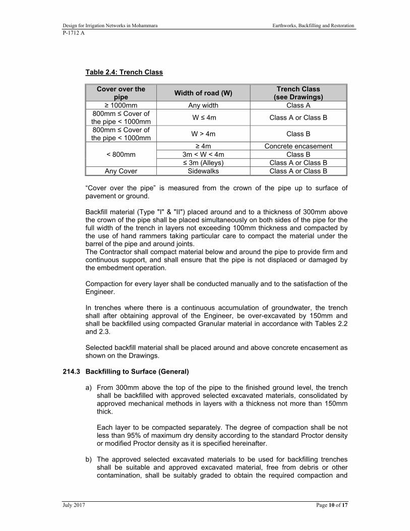
Design for Irrigation Networks in Mohammara Earthworks, Backfilling and Restoration
P-1712 A
July 2017 Page 10 of 17
Table 2.4: Trench Class
Cover over the pipe
Width of road (W) Trench Class
(see Drawings) ≥ 1000mm Any width Class A
800mm ≤ Cover of the pipe < 1000mm
W ≤ 4m Class A or Class B
800mm ≤ Cover of the pipe < 1000mm
W > 4m Class B
< 800mm ≥ 4m Concrete encasement
3m < W < 4m Class B ≤ 3m (Alleys) Class A or Class B
Any Cover Sidewalks Class A or Class B “Cover over the pipe” is measured from the crown of the pipe up to surface of pavement or ground. Backfill material (Type "I" & "II") placed around and to a thickness of 300mm above the crown of the pipe shall be placed simultaneously on both sides of the pipe for the full width of the trench in layers not exceeding 100mm thickness and compacted by the use of hand rammers taking particular care to compact the material under the barrel of the pipe and around joints. The Contractor shall compact material below and around the pipe to provide firm and continuous support, and shall ensure that the pipe is not displaced or damaged by the embedment operation. Compaction for every layer shall be conducted manually and to the satisfaction of the Engineer. In trenches where there is a continuous accumulation of groundwater, the trench shall after obtaining approval of the Engineer, be over-excavated by 150mm and shall be backfilled using compacted Granular material in accordance with Tables 2.2 and 2.3. Selected backfill material shall be placed around and above concrete encasement as shown on the Drawings.
214.3 Backfilling to Surface (General)
a) From 300mm above the top of the pipe to the finished ground level, the trench shall be backfilled with approved selected excavated materials, consolidated by approved mechanical methods in layers with a thickness not more than 150mm thick.
Each layer to be compacted separately. The degree of compaction shall be not less than 95% of maximum dry density according to the standard Proctor density or modified Proctor density as it is specified hereinafter.
b) The approved selected excavated materials to be used for backfilling trenches shall be suitable and approved excavated material, free from debris or other contamination, shall be suitably graded to obtain the required compaction and

Design for Irrigation Networks in Mohammara Earthworks, Backfilling and Restoration
P-1712 A
July 2017 Page 11 of 17
shall not contain stones, rock, or concrete fragments larger than 50mm in any dimension. Suitable fill material shall have plasticity index of less than 10, as determined in accordance with BS 1377-9: 1990 and shall have maximum dry density greater than 1.6 g/cm3 according to the standard Proctor density.
c) The backfilling material shall be deposited and compacted uniformly in layers of
150mm compacted thickness. The Contractor shall provide adequate number of power driver tampers and other compaction equipment and each compaction layer shall be compacted to not less than 95% of maximum dry density.
d) In the event that the filled material is too wet, either due to rain or to excessive
watering or any other reasons, no compaction shall be carried out until the previous and newly placed materials have dried out sufficiently to permit proper compaction. Other precaution shall be taken as may be necessary and directed to obtain the percentages of compaction specified.
e) In the event that excavated material is insufficient or unsuitable for the backfilling
and filling operation on site, the Contractor shall obtain suitable fill material from approved borrow pits. Suitable fill material shall meet the requirements of 214.3 (a –through-d).
f) If pipes are laid in agriculture land, then the top two layers of backfill shall be filled
with agriculture soil originally found at the top before excavation. A land is considered agriculture only if it is outside the residential area and the land use is specified on the zoning map and the line is not laid in place where a road, street, or highway will be constructed in future.
g) Materials used to backfill around manholes shall meet with the Specification set
for the materials used to backfill the trench. But in roads of width greater than 3m, the material around manholes shall be selected, and compacted to meet the requirements of base and sub-base.
214.4 Types of Pavement on Top of Trenches
a) Where the pipeline or box culvert runs transversely underneath asphalt paved roads the top of the trench backfill shall consist of three layers with total thickness of 36 cm. The first layer is of crushed aggregate base course layer 15 cm thick and the second layer of 15 cm thickness of crushed aggregate base course layer mixed with cement in the proportions of 10:1 by weight, with each layer wetted as necessary and compacted to a density at least 100% of modified Proctor. The third layer shall be asphalt layer of 6cm thick. MC70 and RC70 are used for priming the base course and between the asphalt layers at a rate of 1.50 Kg per m2 and 0.60 Kg per m2, respectively.
Edges of existing asphalt shall be sawed into straight lines with no curves or
abrupt edges; with berm width of 15cm on either side of the trench and to a depth of 6cm. All crossing shall be of one straight segment. The Contractor is responsible for cutting, removing and reinstating all pavements cracked or destroyed as a result of his work.
Design for Irrigation Networks in Mohammara Earthworks, Backfilling and Restoration
P-1712 A
July 2017 Page 12 of 17
b) Where the pipeline or box culvert runs longitudinally underneath asphalt paved roads the top of the trench backfill shall consist of three layers with total thickness of 36 cm. The first two layers shall be of crushed aggregate base course layers 15 cm thick, each wetted as necessary and compacted to a density at least 100% of modified Proctor. The third layer shall be asphalt layer of 6 cm thick. MC70 and RC70 are used for priming the base course and between the asphalt layers at a rate of 1.50 Kg per m2 and 0.60 Kg per m2, respectively.
Edges of existing asphalt shall be sawed into straight lines with no curves or abrupt edges; with berm width of 15cm on either side of the trench and to a depth of 6 cm. Each straight segment shall not be less than 50m. The Contractor is responsible of cutting, removing and reinstating all pavement cracked or destroyed as a result of his work.
c) Where the pipeline or box culvert runs underneath concrete pavement in roads,
the top of the trench backfill shall consist of two layers. The first layer shall be crushed aggregate base course 15 cm thick wetted as necessary and compacted to a density at least 100% of modified Proctor and the second layer of 12 cm thickness of reinforced concrete Class C25.
d) Where the pipeline or box culvert runs underneath concrete pavement in alleys,
the top of the trench backfill shall consist of 10 cm plain concrete Class C20. e) Where the pipeline or box culvert runs underneath tile paved roads, the top of the
trench backfill shall consist of three layers of total thickness 38 cm. The first layer shall be crushed aggregate base course 25 cm thick wetted as necessary and compacted to a density at least 100% of modified Proctor and the second layer of 5cm thickness of fine granular material (type A) and the third layer of 8cm thickness of concrete tiles.
f) Where the pipeline or box culvert crosses tile-paved sidewalk or island, the top of
the trench backfill shall consist of three layers with total thickness of 21 cm. The first layer shall be crushed aggregate base course 10 cm thick wetted as necessary and compacted to a density at least 100% of modified Proctor and the second layer shall be 5 cm thick of fine granular material. The third layer shall be concrete tiles 6 cm thick or similar to existing tiles.
g) Where the pipeline or box culvert crosses an asphalt paved sidewalk or island the
top of the trench backfill shall consist of two layers with total thickness of 15 cm. The first is of crushed aggregate base course layer 10 cm thick wetted as necessary and compacted to a density at least 100% of modified Proctor and the second layer shall be asphalt wearing layer of 5 cm thickness of (3/8") aggregate size. MC70 and RC70 are used for priming the base course and between the asphalt layers at a rate of 1.50 Kg per m2 and 0.60 Kg per m2, respectively. Edges of asphalt shall be sawed into straight lines with no curves or abrupt edges.
h) Where the pipeline or box culvert runs underneath a road’s unpaved shoulder,
the top of the trench backfill shall consist of crushed aggregate base course layer 15 cm thick, wetted as necessary and compacted to a density at least 100% of modified Proctor.

Design for Irrigation Networks in Mohammara Earthworks, Backfilling and Restoration
P-1712 A
July 2017 Page 13 of 17
i) Where the pipeline or box culvert runs underneath a road’s paved shoulder, the top of the trench backfill shall consist of two layers with total thickness of 20 cm. The first is of crushed aggregate base course layer 15 cm thick, wetted as necessary and compacted to a density at least 100% of modified Proctor and the second layer of 5cm thick of asphalt wearing. MC70 is used for priming the base course at rate of 1.50 Kg/m2. Edges of asphalt shall be sawed into straight segments with no curves or abrupt edges. Each straight segment shall not be less than 50m with berm width of 15cm on either side of the trench and to a depth of 5cm.
215 BACKFILL FOR AREAS AND UNDERNEATH AND AROUND STRUCTURES
The materials to be used for backfill for septic tanks, cesspits, areas, underneath and around structures (such as culverts, walls…), shall be Granular material obtained either from excavation for the structure and appurtenant works or from borrow pits cleaned and free of clay and stones according to Tables 2.2 and 2.3. The material used for backfill shall be carried out to the lines and grades shown on the Drawings. The backfill material shall completely and firmly fill the spaces between the excavation lines and the structure without leaving any voids. Each layer shall be wetted with clean water to reach the optimum water content. Vibrator compactor of 25 tonne shall be used in compacting each layer. For the backfill, where the 25 tonne vibrator compactor is not available, hand-operated and/or pneumatic tampers approved by the Engineer shall be used for each layer every specific case as suitable.
215.1 Backfill above and under Culvert
Crushed Aggregate Base Course, according to Clause 806, shall be placed underneath concrete culverts and compacted to a density at least 95% of modified Proctor. Thickness of this layer shall be in accordance with the Drawings. The remaining backfill for concrete culverts shall be in accordance with the Drawings
215.2 Backfill for Areas
The backfill for areas shall be carried out in layers not greater than 50cm thick after compaction. The compaction ratio at any depth of each layer when tested according to modified Proctor shall be at least 95% density.
215.3 Backfill underneath and around Structures
The backfill underneath structures shall be carried out in layers not greater than 25cm thick after compaction for a total depth of 1.0m below the foundation level. The compaction ratio at any depth of each layer when tested according to modified Proctor shall be at least 97% density.
216 MAKING GOOD SUBSIDENCES AFTER BACKFILLING

Design for Irrigation Networks in Mohammara Earthworks, Backfilling and Restoration
P-1712 A
July 2017 Page 14 of 17
Backfilling, whether in foundations or in pipe trenches, shall be thoroughly compacted by ramming and any subsidence due to consolidation shall be made up with extra compacted material.
Should subsidence occur after any surface reinstatement has been completed the surface reinstatement shall first be removed, the hollows made up, and then the surface reinstatement relaid.
Any subsidence that occurs adjacent to the Site of the Works which is attributable to the Contractor’s activities shall be reinstated to the full satisfaction of the Engineer.
217 REMOVAL OF TIMBERING FROM EXCAVATIONS
Timbering shall be removed from the excavations before or during the process of backfilling except in so far as this removal of timber would be likely to cause damage to adjacent property, structures or structure foundations in which event the Contractor shall leave in the excavation such timbering as he considers necessary or as may be ordered by the Engineer.
218 REINSTATEMENT OF SURFACES
All surfaces whether public or private which are affected by the Works shall be reinstated temporarily in the first instance and when the ground has consolidated fully the Contractor shall reinstate the surface permanently. Temporary reinstatement and permanent reinstatement of all surfaces, affected by the operations of the Contractor shall be carried out and maintained to the satisfaction of the Engineer and the responsible authority or owner. Temporary reinstatement shall be carried out immediately the trenches are backfilled. Permanent reinstatement shall not be carried out until the ground has considered completely. The Contractor shall inform the Engineer before carrying out this work. In the event of further settlement occurring after the completion of the permanent reinstatement the Contractor shall forthwith make good the reinstatement to the approval of the Engineer or responsible authority. Reinstatement of surfaces shall be executed as indicated on the Drawings. Reinstatement of surfaced roads shall be carried out to the approval of the relevant authority. The responsible authority shall have the right to carry out permanent reinstatement at the Contractors expense. Trenches in open ground shall be reinstated to the condition in which the ground was before excavation was commenced. The final surface of the trench shall be flush with the surrounding ground. In verges and other grass surface and after the backfilling has been thoroughly consolidated the topsoil shall be relaid rolled and planned with grass or other

Design for Irrigation Networks in Mohammara Earthworks, Backfilling and Restoration
P-1712 A
July 2017 Page 15 of 17
vegetation as directed by the Engineer as may be necessary and watered until the grass has become well established. Should planting fail it shall be replanted as required until a satisfactory growth is obtained. If at any time any reinstatement deteriorates the Contractor, shall restore it to a proper condition immediately. Should the Contractor not remedy the defect to the Engineer’s satisfaction forthwith any remedial work considered necessary may be undertaken by the Employer and/or the responsible authority at the Contractor’s expense. All trees, shrubs and plants shall be carefully transplanted and shall be returned to their original location after the refilling of the excavations. Return of old or mature trees may be waived in case where the age of the tree makes return impracticable. Topsoil shall be carefully set aside and replaced at the surface of the backfilling. The trenches shall be refilled and rammed solid as specified in the Contract and shall not be topped up above the original surface level to allow for settlement. If any trench becomes dangerous the Engineer may call upon the Contractor for its reinstatement at three hours’ notice and failing this to have the work done by others at the Contractor’s expense.
Design for Irrigation Networks in Mohammara Earthworks, Backfilling and Restoration
P-1712 A
July 2017 Page 16 of 17
219 SAFETY OF EXCAVATIONS IN ROADS
Where the surface of the road (other than that which lies immediately above the trench) is damaged either by the concentration of traffic caused by an open trench, by subsidence or other causes arising from the operations of the Contractor, he shall permanently reinstate the whole of the surface so damaged to its original condition. The Contractor shall ensure that trenches and reinstatement are maintained in a safe condition and shall take immediate action to remedy any deterioration which renders the works unsafe. If in the opinion of the Engineer any excavation or reinstatement is in a dangerous condition the Contractor shall immediately remedy the defect. Should the Contractor fail to carry the reinstatement promptly the work may be carried out by others at the Contractor’s expense.
220 FORMING BANKS
The filling to be used in the embankments shall be material selected from that arising from surplus excavation, the material being placed according to its nature as shall be directed by the Engineer. The fill shall be placed in layers not exceeding 150mm thick, each layer being thoroughly compacted by an approved roller to the satisfaction of the Engineer.
221 RESTORATION OF BORROW AREAS, SPOIL TIPS AND QUARRIES
Any spoil tips, quarries or other borrow areas developed by the Contractor for the purpose of the Works shall be finished to safe and fair slopes to the approval of the Engineer.
222 TOPSOILING AND GRASSING
Where required, surfaces shall be soiled with fine sifted soil or silt not less than 100 mm compacted thickness which shall be racked and brought to a fine tilth. Surfaces required to be grassed shall be planted with approved local grass at a spacing of 200 mm x 200 mm. The grassed areas shall be replanted if the first or subsequent operation is unfruitful or if for any reason the grass is destroyed. Grassed areas shall be watered and attended until the grass has become well established. The soiling and planting of the grass in slopes shall be carried out immediately the slope is formed and the grass shall be kept weeded and cut until the Works is accepted at the time of the Certificate of Completion.
223 FREE DRAINING FILL
Free draining fill for use as backing to walls shall consist of sound hard stone or broken rock or concrete derived from demolition of structures. The particles shall be roughly cubiform and shall be between 75 mm and 25 mm in size. All smaller particles, dust, rubbish and organic matter shall be excluded.
Design for Irrigation Networks in Mohammara Earthworks, Backfilling and Restoration
P-1712 A
July 2017 Page 17 of 17
224 HARDCORE
Hardcore shall consist of sound hard stone or broken or rock or concrete derived from excavation or demolition of structures and shall be graded from 150 mm to 50mm in size, except that sufficient but not excessive blinding materials of smaller sizes may be permitted at the discussion of the Engineer.
225 STONE PITCHING
Stone pitching (Rip Rap) shall consist of a free draining mixture of broken hard stone obtained from quarries approved by the Engineer which shall have a maximum size of 300 mm and a minimum size of 200 mm. Between these limits the material shall be reasonably well graded.
226 GEOTEXTILE FILTER FABRIC
Geotextiles shall be manufactured from synthetic fibres to form thin permeable membranes. Unless otherwise specified geotextile filter fabrics shall be non woven. The fabric shall allow water to flow though it at right to its principal plane at a rate not less than 10 litre/m2/sec under a constant head of water of 100 mm. Laps in the geotextile fabric shall be not less than 300 mm. The earth against which the geotextile is to be laid shall be free from protrusions or sharp projections which could damage the fabric. The geotextile shall be in continuous contact with the surface on which it is placed and shall not be stretched or bridged over hollows or humps. The geotextile fabric shall sustain a tensile load of 2.5 kN/m at 5% axial strain. The test piece shall be 200 mm wide and have a gauge length of 100 mm. The rate of strain shall be 10% +/-3% per minute. The size distribution of the spaces shall be such that the fabric is able to prevent the migration of fine silt (200 microns).

Design for Irrigation Networks in Mohammara Waterproofing For Structures
P-1712 A
July 2017 Page 1 of 7
THERMAL & MOISTURE PROTECTION
SECTION 400 WATERPROOFING FOR STRUCTURES
PART 1 GENERAL
1.1 SCOPE
This work shall consist of furnishing and placing approved waterproofing membrane and damp proofing course to external concrete surfaces in contact with earth and furnishing and placing non-toxic epoxy coating to internal surfaces of concrete walls, slabs, and beds and furnishing and installing waterstops to waterproof construction and expansion joints, all as shown on the Drawings or as directed by the Engineer.
PART 2 PRODUCTS
2.1 MATERIALS
A. Asphalt A.1 Waterproofing asphalt shall conform to the Specification for Asphalt for Dampproofing and Waterproofing, AASHTO M115 (ASTM D449). NOTE: Type I is for use below ground and Type II for use above ground. A.2 Primer for use with asphalt in waterproofing shall conform to the Specification for Primer for Use With Asphalt in Dampproofing and Waterproofing, AASHTO M116 (ASTM D41).
B. Bitumen B.1 Waterproofing bitumen shall conform to the Specification for Coal-Tar Bitumen for Roofing, Dampproofing, and Waterproofing, AASHTO M118 (ASTM D450). Type II shall be furnished unless otherwise specified. B.2 Primer for use with coal-tar bitumen in dampproofing and waterproofing shall conform to the Specification for Creosote for Priming Coat with Coal-Tar Pitch in Dampproofing and Waterproofing, AASHTO M121 (ASTM D43).
C. Fabric The fabric shall conform to the Specification for Woven Cotton Fabrics Saturated with Bituminous Substances for Use in Waterproofing, AASHTO M117 (ASTM D173). C.1 Self-Adhesive Polyethylene Sheet Flexible, preformed waterproof membrane comprising strong, high density polyethylene film with self-adhesive rubber/bitumen compound, and having the following minimum properties:
Design for Irrigation Networks in Mashta Hannoud and Mohammara Waterproofing For Structures
P-1712 A
July 2017 Page 2 of 7
total thickness : 1.5 mm weight : 1.6 kg/m2 tensile strength : 42 N/mm2 elongation : 210% long.; 160% trans. tear resistance : 340 N/mm long.; 310 N/mm trans. puncture resistance : 220 N 65 mm Man: Servicised Ltd. Ref: Bitu-thene 1000X HC or other equal and approved.
D. Tar for Absorptive Treatment Tar for absorptive treatment shall be a liquid water-gas tar that conforms to the following requirements: - Specific gravity, 25/25oC ............1.030 to 1.100 - Specific viscosity at 40oC (Engler), not more than ........................3.0 - Total distillate, percent by weight, to 300oC, not more than .........50.0 - Bitumen (soluble in carbon disulfide) not less than, percent ......98.0 - Water, not more than, percent.......................................................3.0
E. Tar Seal Coat Tar seal coat shall conform to the Specification for Tar for Use in Road Construction, AASHTO M52, Grade RTCB-5 (ASTM D490).
F. Joint Fillers Filler for use in horizontal and vertical joints in waterproofing work shall be a straight refined oil asphalt conforming to the following requirements: - Flash point: Not less than 232oC. - Softening point: 48.9oC to 54.4oC. - Penetration: At 0oC, 200 grams, 1 minute, not less than 15.At 25oC, 100 grams, 5 seconds, 50 to 60. At 46oC, 50 grams, 5 seconds, not more than 300. - Loss on heating: At 163oC, 50 grams, 5 hours, not more than 0.5 percent. - Ductility: At 25oC, 5 centimeters per minute, not less than 85. - Total bitumen (soluble in carbon disulfide): not less than 99.5 percent.
G. Waterstops G.1 PVC Water Bars: extruded PVC, heavy duty, of the types and sizes shown on the Drawings, and complete with junction pieces.

Design for Irrigation Networks in Mashta Hannoud and Mohammara Waterproofing For Structures
P-1712 A
July 2017 Page 3 of 7
Man: Expandite Ltd. Man: Greenstreak Plastic Products Man: Servicised Ltd or other equal and approved. G.2 Copper Water Stops: Copper water stops shall be copper sheets of the thickness shown on the Drawings and shall conform to the requirements of AASHTO M138 (ASTM B152). G.3 Rubber Water Stops: Plain rubber water stops shall be formed from a stock composed of a high grade compound made exclusively from new plantation rubber, reinforcing carbon black, zinc oxide, accelerators, anti-oxidants, and softeners. This compound shall contain not less than 72 percent by volume of new plantation rubber. The tensile strength shall be not less than 246kg per sq.cm, with an elongation at breaking of 550 percent when tested in accordance with ASTM D412. The unit stresses producing 300 percent and 500 percent elongation shall be not less than 77kg. and 198kg. per sq.cm, respectively. The Shore Durometer indication (hardness) shall be between 55 and 65 when tested in accordance with ASTM D676. After 7 days in air at 126 degrees (plus or minus 1 degree)C or after 48 hours in oxygen at 126 degrees (plus or minus 1 degree)C both at 21kg per sq.cm, the tensile strength and elongation shall not be less than 65 percent of the original when tested in accordance with ASTM D572. G.4 Synthetic Rubber Water Stops: Synthetic rubber water stops shall be formed from a compound made exclusively from neoprene, or SBR, reinforcing carbon black, zinc oxide, polymerization agents, and softeners. This compound shall contain not less than 70 percent by volume of neoprene or SBR. The tensile strength shall be not less than 175kg. per square centimeter with an elongation at breaking of 425 percent when tested in accordance with ASTM D412. The Shore Durometer indication (hardness) shall be between 50 and 70 when tested in accordance with ASTM D676. After 7 days in air at 126 degrees (plus or minus 1 degree)C or after 48 hours in oxygen at 126 degrees (plus or minus 1 degree)C, and 21kg per sq.cm. pressure, the tensile strength shall be not less than 65 percent of the original when tested in accordance with ASTM D572.
H. Proprietary Waterproofing Systems Proprietary waterproofing systems shall be bituminous membranes reinforced with layers of suitable reinforcement, bituminous coated polythene sheet, plasticized polyvinyl chloride sheet, other approved membranes or applications of resinous reinforced coatings. The type to be used shall be defined on the Drawings and shall be chosen according to its location and serviceability. The specific system shall be approved after site trials, should the Engineer decide these to be necessary.
I. Non-Toxic Epoxy Coating System An approved non-toxic epoxy coating system shall be furnished and applied for all internal concrete surfaces of tanks, culverts and open channels as shown on the Drawings or as directed by the Engineer. The thickness of the non-toxic epoxy coating shall be at least 400 (microns) in accordance with the manufacturer's recommendations.
PART 3 EXECUTION 3.1 SURFACE PREPARATION
A. Waterproofing

Design for Irrigation Networks in Mashta Hannoud and Mohammara Waterproofing For Structures
P-1712 A
July 2017 Page 4 of 7
A.1 All concrete surfaces which are to be waterproofed shall be reasonably smooth and free from projections or holes which might cause puncture of the membrane. The surface shall be dry, so as to prevent the formation of steam when the hot asphalt or tar is applied, and, immediately before the application of the waterproofing, the surface shall be thoroughly cleaned of dust projecting tying wire and loose material. A.2 No waterproofing shall be done in wet weather, nor when the temperature is below 4 degrees C, without special authorization from the Engineer. Should the surface of the concrete become temporarily damp, it shall be covered with a 2-inch (50mm) layer of hot sand, which shall be allowed to remain in place from 1 to 2 hours, or long enough to produce a warm and surface-dried condition, after which the sand shall be swept back, uncovering sufficient surface for beginning work, and the operation repeated as the work progresses.
B. Dampproofing The surface to which the dampproofing coating is to be applied shall be cleaned of all loose and foreign material and dirt and shall be dry. When necessary the Engineer may require the surface to be scrubbed with water and a stiff brush, after which the surface shall be allowed to dry before application of the primer. 3.2 INSPECTION, DELIVERY AND STORAGE
A. All waterproofing materials shall be tested before shipment. Unless otherwise ordered by the Engineer, they shall be tested at the place of manufacture, and, when so tested, a copy of the test results shall be sent to the Engineer by the chemist or inspection bureau which has been designated to make the tests, and each package shall have affixed to it a label, seal, or other mark of identification, showing that it has been tested and found acceptable, and identifying the package with the laboratory tests.
B. Factory inspection is preferred, but in lieu thereof, the Engineer may order that representative samples, properly identified, be sent to him for test prior to shipment of the materials. After delivery of the materials, representative check samples shall be taken which shall determine the acceptability of the materials.
C. All materials shall be delivered to the work in original containers, plainly marked with the manufacturer's brand or label.
D. Waterproofing and dampproofing material shall be stored in a dry, protected place. Rolls of waterproofing fabric and membranes shall not be stored on end.
3.3 CONSTRUCTION
A. Asphalt and Bitumen Waterproofing Membranes A.1 Asphalt shall be heated to a temperature between 148.7 degrees C and 176.5 degrees C and tar for hot application shall be heated to a temperature between 93.3 degrees C and 121 degrees C with frequent stirring to avoid local overheating. The heating kettles shall be equipped with thermometers. A.2 In all cases, the waterproofing shall begin at the low point of the surface to be waterproofed, so that water will run over and not against or along the laps.

Design for Irrigation Networks in Mashta Hannoud and Mohammara Waterproofing For Structures
P-1712 A
July 2017 Page 5 of 7
A.3 The first strip of fabric shall be of half-width; the second shall be full-width, lapped the full-width of the first sheet; and the third and each succeeding strip shall be full-width and lapped so that there will be two layers of fabric at all points with laps not less than 0.051m wide. All end laps shall be at least 0.305m. A.4 Beginning at the low point of the surface to be waterproofed, a coating of primer shall be applied and allowed to dry before the first coat of asphalt is applied. The waterproofing shall then be applied as follows. A.5 Beginning at the low point of the surface to be waterproofed, a section about 0.5m wide and the full length of the surface shall be mopped with the hot asphalt or tar, and there shall be rolled into it, immediately following the mopping, the first strip of fabric, or half-width, which shall be carefully pressed into place so as to eliminate all air bubbles and obtain close conformity with the surface. This strip and an adjacent section of the surface of a width equal to slightly more than half of the width of the fabric being used shall then be mopped with hot asphalt or tar, and a full width of the fabric shall be rolled into this, completely covering the first strip, and pressed into place as before. This second strip and an adjacent section of the concrete surface shall then be mopped with hot asphalt or tar and the third strip of fabric "shingled" on so as to lap the first strip not less than 0.051m. This process shall be continued until the entire surface is covered, each strip of fabric lapping at least 0.051m over the last strip. The entire surface shall then be given a final mopping of hot asphalt or tar. A.6 The completed waterproofing shall be a firmly bonded membrane composed of two layers of fabric and three moppings of asphalt or tar, together with a coating of primer. Under no circumstances shall one layer of fabric touch another layer at any point or touch the surface, as there must be at least three complete moppings of asphalt or tar. A.7 In all cases the mopping on concrete shall cover the surface so that no gray spots appear, and on cloth it shall be sufficiently heavy to completely conceal the weave. On horizontal surfaces not less than 48.9 ltr of asphalt or tar shall be used for each 10.0 sq.m. of finished work, and on vertical surfaces not less than 61.12 ltr shall be used. The work shall be so regulated that, at the close of a day's work, all cloth that is laid shall have received the final mopping of asphalt or tar. Special care shall be taken at all laps to see that they are thoroughly sealed down. A.8 At the edges of the membrane and at any points where it is punctured by such appurtenances as drains or pipes, suitable provisions shall be made to prevent water from getting between the waterproofing and the waterproofed surface. A.9 All flashing at curbs and against girders, spandrel walls, etc., shall be done with separate sheets lapping the main membrane not less than 0.305m. Flashing shall be closely sealed either with a metal counter-flashing or by embedding the upper edges of the flashing in a groove poured full of joint filler. A.10 Joints which are essentially open joints but which are not designed to provide for expansion shall first be caulked with oakum and lead wool and then filled with hot joint filler. A.11 Expansion joints, both horizontal and vertical, shall be provided with sheet copper or lead in "U" or "V" form in accordance with the details. After the membrane has been placed, the joint shall be filled with hot joint filler. The membrane shall be carried continuously across all expansion joints. A.12 At the ends of the structure the membrane shall be carried well down on the abutments and suitable provision made for all movement.
B. Proprietary Waterproofing Membranes

Design for Irrigation Networks in Mashta Hannoud and Mohammara Waterproofing For Structures
P-1712 A
July 2017 Page 6 of 7
Proprietary waterproofing membranes shall be installed strictly in accordance with the manufacturer's instructions and shall be laid so that no air is trapped between it and the concrete surface or between successive layers of sheeting. Unless otherwise specified joints between sheets shall be lapped with end laps of at least 150mm and side laps of at least 100mm. The joints shall be arranged so that at no points are there more than three thicknesses of sheeting and, as far as possible so that water will drain away from the exposed edge.
C. Damage Patching of Waterproofing Membranes C.1 Care shall be taken to prevent injury to the finished membrane by the passage over it of men or wheelbarrows, or by throwing any material on it. Any damage which may occur shall be repaired by patching. Patches shall extend at least 0.305m beyond the outermost damaged portion and the second ply shall extend at least 0.076m beyond the first. C.2 Proprietary waterproofing membranes shall be repaired according to the manufacturer's specifications and as directed by the Engineer.
D. Dampproofing D.1 Concrete, brick, or other surfaces that are to be protected by dampproofing shall be thoroughly clean before the primer is applied. They shall then be brush or spray painted with two or more coats (as indicated on the Drawings) of tar or asphalt for absorptive treatment. Below ground not less than two coats shall be applied, using 0.56 ltr per sq.m. of surface. On the well-primed surface one application of tar or asphalt seal coat shall be applied by brush, using 0.45 ltr per sq.m. D.2 Care shall be taken to confine all paints to the areas to be waterproofed and to prevent disfigurement of any other parts of the structure by dripping or spreading of the tar or asphalt.
E. Protection of Waterproofing and Dampproofing E.1 Over the waterproofing membrane and dampproofing course, there shall be constructed a protection course which, unless otherwise specified or shown on the Drawings, shall be a 0.05m course of mortar mixed in the proportion of one part Portland cement and two parts sand. This mortar course shall be reinforced midway between its top and bottom surfaces with wire netting of 0.15m mesh and No. 12 gauge, or its equivalent. The top surface shall be troweled to a smooth, hard finish and, where required, true to grade. E.2 The construction of the protection course shall follow the waterproofing so closely that the latter will not be exposed without protection for more than 24 hours. E.3 Unless otherwise shown on the Drawings or directed by the Engineer, vertical faces waterproofed or dampproofed shall be protected by a porous concrete block wall of not less than 225mm thickness. If approved by the Engineer, a proprietary synthetic sheeting may be used as the protective layer in lieu of the porous concrete block wall.

Design for Irrigation Networks in Mashta Hannoud and Mohammara Waterproofing For Structures
P-1712 A
July 2017 Page 7 of 7
F. Water Stops F.1 Copper Water Stops: Copper sheets for water stops shall be of the width and shall be bent to the shapes shown or ordered. The sheet copper in each joint shall be continuous, separate pieces being connected by thoroughly workmanlike soldered joints to form a complete watertight unit. The sheet copper shall be placed in such manner as to ensure its embedment in the concrete on each side of the joints in the positions shown on the Drawings. F.2 Rubber Water Stops: Rubber water stops shall be installed in accordance with the details shown on the Drawings. The water stops shall be formed with an integral cross section which shall be uniform within 3mm in width and the web thickness or bulb diameter, within plus 1.5mm and minus 0.75mm. No splices shall be permitted in straight strips. Strips and special connection pieces shall be well cured in a manner such that any cross section shall be dense, homogenous, and free from all porosity. All junctions in the special connection pieces shall be full molded. During the vulcanizing period the joints shall be securely held by suitable clamps. The material at the splices shall be dense and homogenous throughout the cross section. Field splices shall be either vulcanized, mechanical, using stainless steel parts, or made with a rubber splicing union of the same stock as the water stop, at the option of the Contractor. All finished splices shall demonstrate a tensile strength of not less than 50 percent of the unspliced material.
G. Testing Unless otherwise agreed by the Engineer in writing, at least one site trial application of the waterproofing system shall be carried out to determine the suitability of the surface preparation, method of application and effectiveness of the protective layer. The size of membrane laid shall be not less than 2.0 meters wide and 5.0 meters long.
END OF SECTION