slflll reproduction of all or part of this report is authorized. z this report was prepared by: t o...
TRANSCRIPT
7 AD-A173 8O42 SOLVING GLOBAL TWO DIMENSIONAL ROUTING PROBLEMS USING ~1InSNELL' S LAW AND A* SERRCH(U) NAVAL POSTGRADUATE SCHOOLMONTEREY CA R F RICHBOURG ET AL OCT 86 NP552-BG-02i
UNCLASSIFIED F/G 9/2 RL
Slflll....ff

g-I
NATIONAItPURFAU OF STANDARDS-)N93 -A
'I

NPS52-86-021
NAVAL POSTGRADUATE SCHOOLt
Monterey, California00
Tm.
D "TIC
SOLVING GLOBAL TWO DIMENSIONAL ROUTING PROBLEMS
USING SNELL'S LAW AND A* SEARCH
R. F. Richbourg
Neil C. Rowe
Michael J. Zyda
Robert B. McGhee
-- October 1986
be..ko - l mIId 6" 00
~6 1110 O~

NAVAL POSTGRADUATE SCHOOLMonterey, California
Rear Admiral R. C. Austin D. A. Schrady
Superintendent Provost
" This work was supported in part by the U.S. Army Combat Development Experimentation
Z Center (USACDEC) under MIPR ATEC 46-86 and in part by funds provided through theW Commodore Grace Murray Hopper Research Chair in Computer Science at the NavalLX Postgraduate School.
z Reproduction of all or part of this report is authorized.
Z This report was prepared by:
t
o .MICHAEL J. ZYDA
Assistant Professor
Department of Computer Science
0
W Reviewed by: Released by:
VINCENT Y. LU KNEALE T. MARSHALLChairman Dean of Information & Policy ScienceDepartment of Computer Science
%Il

UNCLASSIFIEDSECURITY CLASSIFICATION OF THIS PAGE (IRhen Deft Unrt0_________________
REPORT DOCUMENTATION PAGE BFRED COMPLETINORMIREPOR NUMGER "NO3. PIENTS CTLGHME
NPS52-86-021 GA W. _ 3 AAO4. TITLE (and Subtitle) S. TYPE Of REPORT I PERIOD COVEREDSOLVING GLOBAL TWO DIMENSIONAL ROUTING PROBLEMSUSING SNELL'S LAW AND A* SEARCH
a. PERFORMING ORG. REPORT NuM11ER
7. AUTI4Onee) I. CONrTACT ORf GRANT NUNIER(e)
R. F. Richbourg Michael J. ZydaNeil C. Rowe Robert B. McGhee
W 9. PERFORMING ORGANIZATION NAME AND ADDRESS 10. PROGRAM ELEMENT. PROJECT. TASKin AREA 4 WORK UNIT NUM§ERS
Z Naval Postgraduate SchoolSd Monterey, CA 93943-5100L.x
W 1. CONTROLLING OFFICE NAME AND ADDRESS 12. REPORT DATEI-z Chief of Naval Research October 1986
Arlington, VA 22217 I3. Um8ER Of PAGES
z __ ___ ____ ___ ____ ___ ____ ___ ____ ___ ___32
14. MONITORING AGENCY NAMIE 6 ADDRIESSI different from Controlling Office) IS. SECURITY CLASS. (of this report)
o Unclassified0 ISs. DECLASSIFICATION, DOWNGRADING0- SCHEDULE4 ____________________________ _______________
It. DISTRIUUTION STATEMENT (of this Report)
SdApproved for public release; distribution unlimited
I.
17. DISTRIBUTION STATEMENT (of the abstract entered In block 20. It diffeorent fromt Report)
III. SUPPLEMENTARY NOTES
19. KEY WORDS (Continue on reverse side it necessary and identify by block number)
20. AISTRACT (Continue on reverse aide it necessay and Identify by block nienber)
Long range route planning based on map data is an important component inthe intelligent control system of an autonomous agent. Most attempts to solvethis problem rely on applying simple search strategies to high resolution, nodeand link representations of the map. These techniques have several disadvan-tages including large time and space'"requirements. We present a solution
____ technique which utilizes a more intelligent representation of the problem en-vironment. Topographical features are represented as homogeneous cost regions,
-r'.' greatly reducing storaae reauirements. Given this representation, the A* sear
DD I JAN 73 1473 EDITION OFr I NOV 'i 5 S OSOLEWE UNCLASSIFIEDS 'N 0 102. LF- 014- 6601 SECURITY CLASSIFICATION OF1 THIS PAOE (W9he Data 11000-01

UNCLASSIFIED
SECURiTY CLASSIFICATION OF THIS PAGE (Wfhm Onte Snur
stragegy is applied to a dynamically created graph that is constructed accord-ing to Snell's law. Testing has shown that this strategy reduces time require-ments in many cases.
AOcession Tor
IMS GRA&IDTIC TABUnannounlcedJustification------
By-
Distribution/Availability Codel
Avail and/or
Dist special
4>
S, N 0102- LF- 014- 6601 UNCLASSIFIED
SEuITY CLASSIFICATION OF THIS PAG~fftn Dae Etered)
'l It r

SOLVING GLOBAL, TWO DIMENSIONAL ROUTING PROBLEMSUSING SNELL'S LAW AND A* SEARCH-,
R. F. Richbourg, Neil C. Rowe, Michael J. Zyda, Robert B. MeGhee
Department of Computer Science, Naval Postgraduate School, Monterey, California
Abstract
Long range route planning based on map data is an important component in the intelligent
control system of an autonomous agent. Most attempts to solve this problem rely on applying sim-
ple search strategies to high resolution, node and link representations of the map. These techniques
have several disadvantages including large time and space requirements. -We- present a solution
technique which utilizes a more intelligent representation of the problem environment. Topograph-
ical features are represented as homogeneous cost regions, greatly reducing storage requirements.
Given this representation, the A* search strategy is applied to a dynamically created graph that is
constructed according to Snell's law. Testing has shown that this strategy reduces time require-
ments in many cases.
1. Introduction
An important component of any intelligent control scheme for autonomous agents is a route
planning ability. The route planning problem has two basic forms. Planning for local motions is
the most well studied and most easily solved problem. Local motion planning is generally limited
to reasoning about movements within the area local to the autonomous agent, local in the sense
that the environment is within scanning range of the agent's sensor equipment. Because of the
localized environment, the problem typically assumes a binary nature: every point in the environ-
ment is classified as either impassable (part of an obstacle) or passable. To solve this problem, the
environment must be described as a set of polygons defining obstacle boundaries. Any point not
, p t This work was supported in part by the U.S. Army Combat Developments Experimentation Center
% (USACDEC) under MIPR ATEC 46-S6 and in part by funds provided through the Commodore Grace MurrayHopper Research Chair in Computer Science at the Naval Postgraduate School.

2 I
inside an obstacle polygon is traversable. Then. a graph, G= ( V.L), is created where V is a set of
points including all obstacle vertices as well as the start and goal location lRef. 1:. The set L con-
tains a link between any two members of V that can be connected by an unobstructed line seg-
ment. Given this representation, the problem is reduced to finding the shortest distance path in a
graph, a problem that can be solved by several standard techniques. There are several variations
on this general approach IRef. 2,3,4).
The second class of route planning problems is intended to provide routes over long ranges.
Here, some form of map is required since the range of movement is too great to be sensed by the
on-board equipment of the agent. A more important difference is that the binary nature of the
local route planning problem is invalidated. Because of the great diversity that occurs in the physi-
cal world, it is not reasonable to assume that all passable areas have the same traversal costs. As
an example, riding a bicycle through wet sand requires much more time and effort than riding on a
roadway. Thus, the best path for a bicycle rider between two points on a sandy beach could easily
be a longer distance roadway route when the alternative is the shortest distance route across the
sand.
2. Wavefront Propagation
The best understood and most often used method to solve the long range routing problem is
characterized as a wavefront propagation technique IRef 5,6;. To employ this technique. the map
provided to the agent must be a lattice. The ratio of the number of points in the lattice to the phy-
sical distance represented by the map determines the resolution of the problem. Each lattice point
has a link to each of its immediately adjacent neighbors (normally the eight neighboring points,
although the degree of connectivity can be any multiple of four). A cost is associated with each
link. This cost is meant to represent the cost for the agent to traverse the corresponding area in the
physical environment. (Links to points within obstacle areas have infinite cost.) A solution route
is generated by first "positioning" the agent at either the start or goal (or both if a bidirectional
strategy is employed). Then, the algorithm simulates the passage of time while the agent is
allowed to "move" in all directions. The effect is to generate a series of wavefronts, depicting

f possible locations for the agent at successive instances of time. When the wavefront reaches the
goal, a solution path is retrieved by referencing backpointers, solving wavefront gradients, or a
similar technique.
The wavefront technique can solve the long range routing problem. However, there are
several drawbacks to using the method [Ref. 71. First, an omnidirectional search of a high resolu-
tion lattice can be expensive computationally. The number of cells that must be examined is
roughly proportional to the number of cells in a circle with a radius equal to the number of cells
between the start and goal. There is also a digital bias inherent in the lattice representation that
results in "stair step" approximations to straight line segments [Ref. 61. Because of this, the
method may return a set of digitally equivalent approximations to the optimal path. Another
expensive procedure is required to deduce the true, non-digitally biased optimal solution from this
set. Finally, most of the search effort is wasted in unproductive portions of the lattice.
3. Snell's Law Based Route Planning
It has been shown that Snell's law, commonly used in optics, also characterizes minimal cost
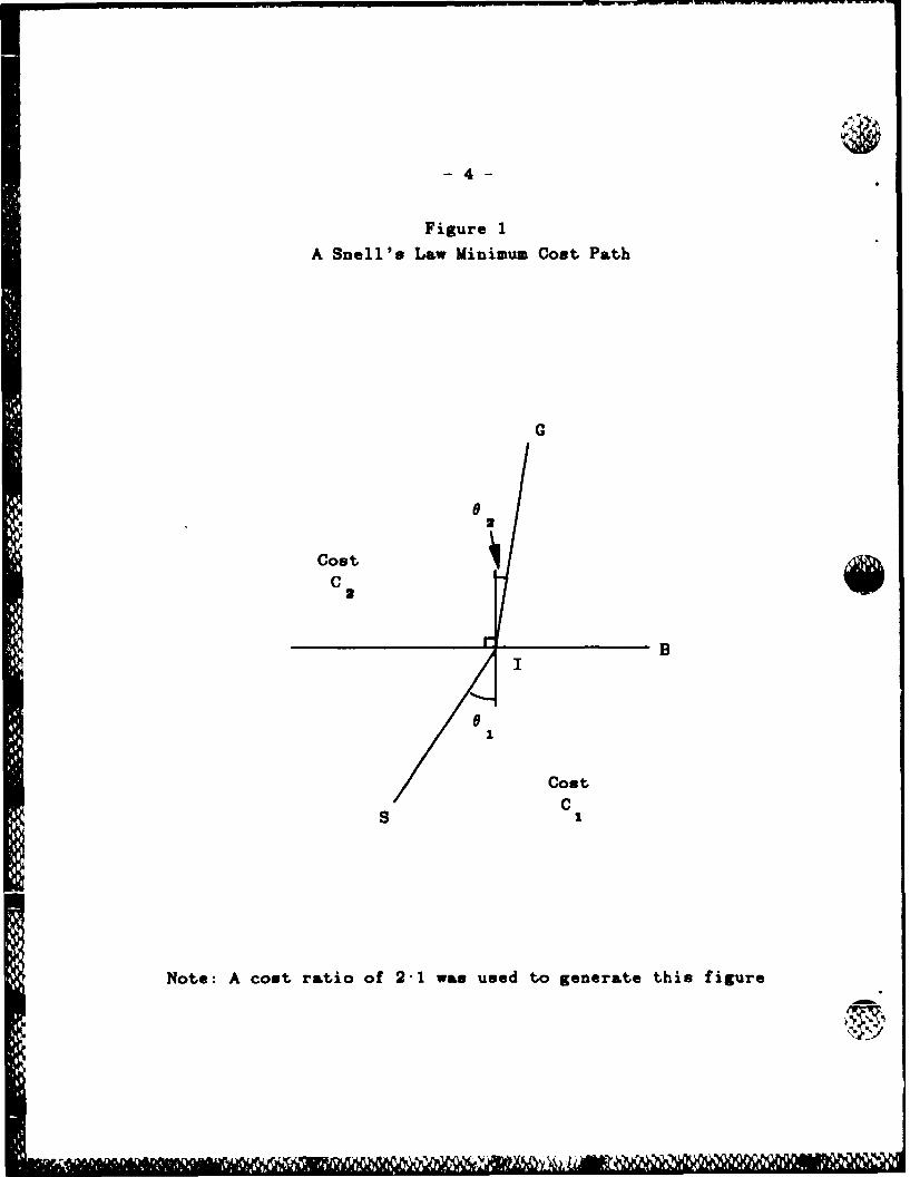
paths in the long range routing problem [Ref. 7,81. We illustrate the rule in Figure 1. Let B
denote a linear boundary so that the cost accrued per unit of distance traveled on one side of B is
C, and on the other side of B is C2. Then the (S,I,G) path is the minimal cost path between S
sin($,) sin(P.)and G if and only if - = . (Note that 01 is the angle between the (S,1) segment and a
C3 C2
normal to B while 02 is the angle between the (1,G) segment and a normal to B. Also, in Figure 1,
C., is more expensive than C,.) This rule is intuitively appealing. Snell's law forces a straight line
between S and G to be bent so that increased distance in the low cost region (C,) is traded for
decreased path distance in the high cost (C2 ) area.
Application of Snell's law relies on a homogeneous region cost map !Ref. 9j (as opposed to
the discrete node and link representation of a continuous environment used in the wavefront tech-
nique). Thus, there is no digital bias in the solution paths and the computational cost of the algo-
rithm is not tied to map resolution or the distance between start and goal. However, there are
-1 11 'l C 1 11
4-
Figure 1
A Snell's Law Minimum Cost Path
Cost
B
CostC
S
Note: A cost ratio of 2-1 was used to generate this figure

difficulties in applying Snell's law to the homogeneous cost region representation of the environ-
ment. First, there is no known closed form solution for a Snell's law problem; using the rule
requires iterative search. Secondly, the law allows "blind regions" to exist. Blind regions occur
when there are areas on the map that can not be reached by any path obeying Snell's law.
4. A Suitable Problem Representation
The Snell's law based solution method requires a map of the environment where homogene-
ous cost regions are presented. A homogeneous cost region IRef. 91 is an area defined by an arbi-
trary polygon such that all points inside the polygon have identical traversal costs. That is, when-
ever an agent is inside a homogeneous cost region, the cost for that agent to travel one unit of dis-
tance in any direction is constant.
For simplicity of discussion, we assume a ternary classification scheme for constructing the
homogeneous cost regions 'Ref. 71. Each point in the physical world is classified into one of three
disjoint sets, either obstacle, traversable at high cost, or traversable at low cost. Contiguous areas
that have the same traversal classification are grouped together into polygons describing the homo-
geneous cost regions. The low cost (optimal) regions need not be specifically represented. We
assume that these areas constitute the "background" for the map. Thus, obstacle and high cost
regions are overlaid onto the optimal cost background.
5. Search and Snell's Law
There is no known closed form solution for a Snell's law problem. Instead, some iterative
technique such as bisection or golden section search must be employed. The requirement for search
interacts with the fact that Snell's law allows blind regions to exist. Figure 2 exemplifies this
dilemma. Suppose that we desire the minimal cost path from S to G and that the high cost region
* represented by a triangle lies between them. P2 is a Snell's law path from S through vertex V that
is refracted by intersecting sides B2 and B. of the high cost region. P2 is a path that begins at S
and travels infinitesimally close to vertex V so that the high cost region is not intersected. Because
of the relative positions of P, and P., point G is in a blind region. Any Snell's law path that inter-
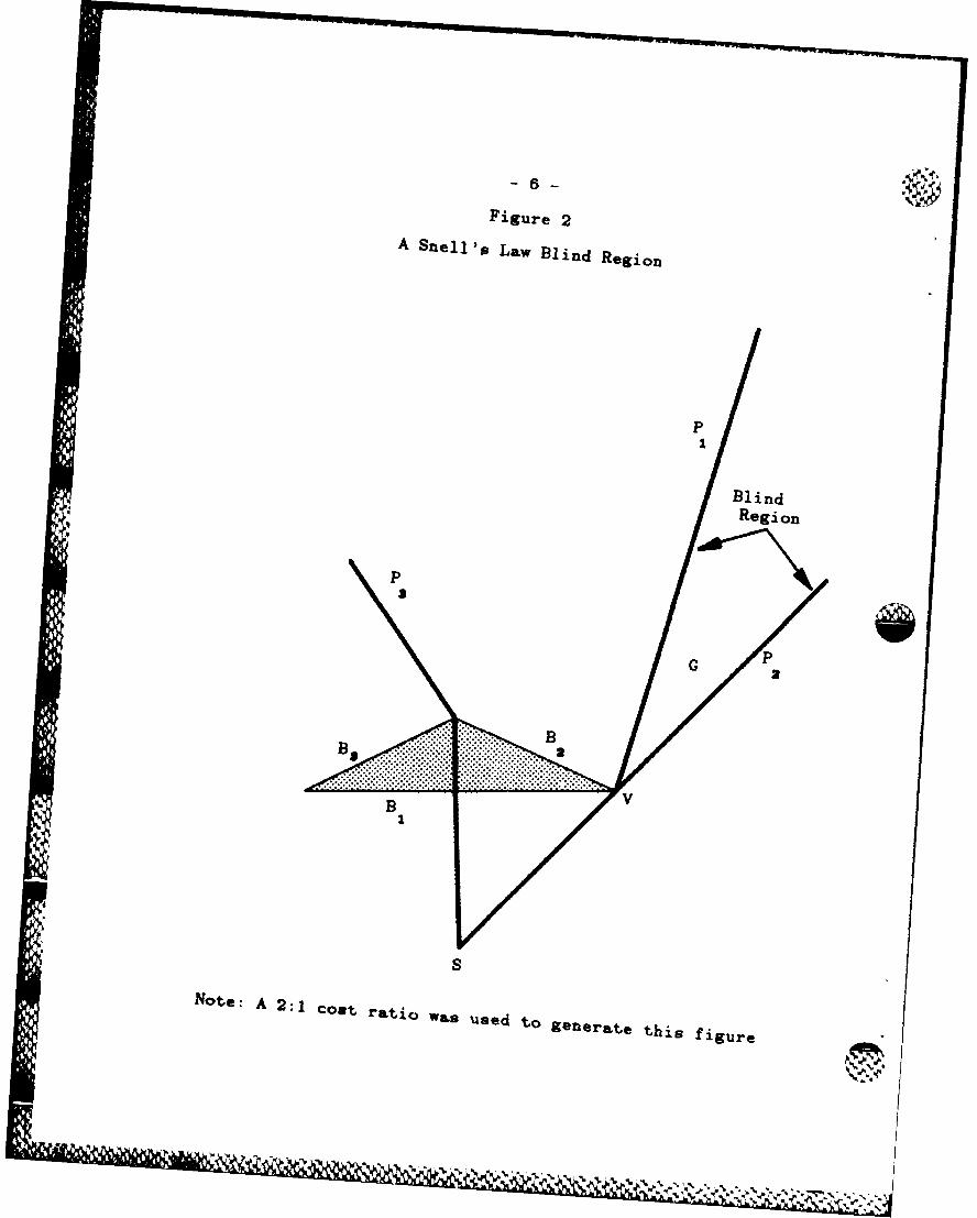
Figure 2
A Snell's Law Blind Region
BlindRegion
G S
B
S
Note: A 2:1 cost ratio was used to generate this figure

7 -
sects the high cost region to the left of V will be entirely to the left of Pi. An analogous situation
exists involving paths to the right of V and P2. Thus, no Snell's law path from S to C exists and
any iterative search based on the law will clearly fail. The only points that can be reached by a
Snell's law path involving sides B1 and B2 of the high cost region lie in the area between P. on the
left and P1 on the right.
Because of the existence of blind regions, we must insure the success of an iterative search
before the search process begins. Thus, we must insure that the see ch space under consideration
"contains" the point that is to be the object of the search. We insure this property by creating
"'wedges" F Ref. 81 within the search space. Wedges define the portions of the map that can be
reached by Snell's law paths from a specified point and involve a specific set of region boundaries.
In Figure 2. paths P. and P, form a wedge that begins at point S and involves sides B, and B2 of
the high cost region.
Creating the wedges serves another important purpose. Iterative search techniques use the
information gained from one iteration to guide successive attempts. Thus, consecutive attempts
.4 must provide consistent information. To guarantee consistency between successive Snell's law
paths. we must insure that the paths all intersect exactly the same sequence of region boundaries.
In Figure 3, path P1 intersects boundaries B, and B2 of the high cost region while path P2 inter-
sects B, and B3. In searching for an S to G path. Pi indicates that the next attempt should inter-
sect boundary B, between V', and 11, while P2 indicates that the interval between 12 and V' is the
most promising. Clearly, the information here is inconsistent and any iterative search technique
will be confounded
To correct the situation in Figure 3, the original wedge formed by P, and P2 should be
refined by creating new wedges associated with vertex V, of the high cost region. This implies a
general principle. Once a wedge has been formed, the information available within that wedge is
only guaranteed to be consistent up to the closest unsolved region vertex. A region vertex is
unsolved if a Snell's law path (within the wedge) to that vertex ha% not yet been found. As an
example, vertex V, in Figure 3 is an unsolved vertex.

Figure 3
Inconsistent Search Information
G+P2
P
1
BB
VV
~Notes: A 2:1 cost ratio was used to generate this figure.
Point S is "off center" so that the ray pattern is asymmetric.
V
.. .. .. .

-9-
Once a Snell's law path to a vertex within a wedge has been found, three new wedges can be
formed. In Figure 4, V3 is the closest unsolved vertex and the Snell's law path from S, across
boundary B1 to V3 has been found. Any Snell's law path that intersects B3 to the left of I will
intersect B 2 to the left of V3. Similarly, any Snell's law path intersecting B, to the right of I will
intersect B 3 to the right of V. Thus, to create new wedges guaranteeing the same sequence of
region boundaries will be intersected, we split the (SI, V13) path into two Snell's law paths at V3.
Figure 5 depicts the result of splitting the path at V3. Two new paths, PL (intersecting B, and B.)
and PR (intersecting B1 and B.,), have been created. They refine the original wedge formed by Pi
and P 2 into new wedges including one formed by P, and PL and another wedge defined by Pit and
P 2. There is also a third wedge, that formed by path PL and PR. In Figure 5, This last wedge con-
tains no points since PL and PR intersect each other immediately at vertex V . However, in Figure
2, P, and P2. define a similar wedge that is not empty. Here, the wedge is a blind region and is not
direc tly reachable by any Snell's law path. To reach points inside the blind region, such as G in
Figure 2. adherence to Snell's law must be temporarily abandoned at the point initiating the blind
region (vertex V in Figure 2). The law is then reapplied in the further search within the wedge (i.e.
beyond vertex V in Figure 2).
Thus, we have a general strategy to apply Snell's law in the search for optimal paths. Given
an initial wedge, find the closest unsolved vertex that it contains. Find the Snell's law path to the
unsolved vertex. Split the path into two paths at the vertex so that the original wedge is refined
into three new wedges. Each refinement extends the number of boundaries that are guaranteed to
be intersected by any Snell's law path within each new wedge.
6. The Initial Wedge
Given a homogeneous region cost map and a start and goal location, the shortest distance
start to goal path can be found by ignoring the high cost region polygons and applying binary case
methods to the remaining obstacle regions. Clearly, such a path may not have optimal cost, but it
IN -.4". must be a feasible solution. The cost of traversing this shortest distance path can be computed by
allowing the high cost region polygons back into the cost map. The resulting cost is an upper

-10-
Figure 4A Snell's Law Path to an Unreached Vertex
P2
P
V
S
Note: A 2:1 cost ratio wan used to generate this figure.
II *

Figure-Refinemlent of the Original Wedge
2
P1p
PpIL
vP
V3
Note: A 2:1 cost ratio was used to generate this figure.

12
bound on the cost of the optimal start to goal path. Given an upper bound, physical limits that
must contain the optimal path can be constructed. Suppose there is some path from start to goal
that stays entirely within the optimal cost regions. The maximum distance that can be traveled
along such a path while not accruing cost greater than that of the shortest distance path Can be
computed. Call this maximum distance the bounding distance. The set of all points such that the
distance from the start to that point added to the distance from that point to the goal is equal to
the bounding distance defines an ellipse that has the start and goal locations as foci. The optimal
path must lie entirely within the physical limits defined by the ellipse boundary. By definition, any
path that exits the ellipse must have cost greater than that of the shortest distance path. Note that
the ellipse defines the search space for the problem. Only those homogeneous regions that are at
least partially within the ellipse need be considered.
For computational simplicity, circumscribe the ellipse by a rectangle so that each side of the
rectangle is tangent to the ellipse. Call this rectangle the bounding box. To create the initial
wedges, project one Snell's law path towards a normal intersection with the counter-clockwise side
of the bounding box. Project a similar path towards the clockwise side of the bounding box. These
two Snell's law paths define two initial wedges. as depicted in Figure 6. It is apparent that the
lower wedge of Figure 6 is superfluous. This may not be true in all instances, since the optimal
path may occasionally travel away from the goal. As an example, it may be beneficial to take the
shortest way out of a high cost area, regardless of the direction to the goal.
7. Pruning Criteria
Given that we can create wedges over a finite space. we can simply continue to refine and
search all wedges, finding all feasible (i.e. locally optimal) start to goal paths within the search
space. Then, to find the optimal path, select the best feasible solution. However, such a brute force
search can be excessive, computation ally.- Also, it is possible to prune some wedges (and thus their
further refinements) from the search space.
First, consider those wedges that are associated with blind regions. Any start to goal path
within such a wedge must include the known path from the start to the region vertex at the base

-13-
Figure 6
Initialization
bounding box
G
clockwise
\:...../.
initial path to clockwise
side
Note: The ellipse and bounding box were not generated by
• actual data. They are for illustrative purposes only.

- 14-
of the blind region. The true cost of this path can be computed. A lower bound estimate on com-
pleting the path is available if we calculate the remaining distance from the region vertex to the
goal and assume that this distance could be traveled at the optimal cost. Summing the estimated
and the true costs results in a lower bound estimate for any start to goal path within the wedge. If
the estimate exceeds the current upper bound cost of the optimal solution, the wedge can be
pruned. Also, if there is some other path from the start to the vertex at the base of the blind
region, and the other path has a lower start to vertex true cost, the new, higher cost wedge can be
pruned since it must be true that the optimal start to goal path is also the optimal path to all
points on the path itself. Otherwise, the optimal start to goal path can be "shortcut". resulting in
a lower cost path.
Wedges not associated with blind regions can also be pruned. One purpose of building the
wedges is that of constantly increasing the known boundaries which must be crossed by Snell's law
paths within the wedge. There is a minimum cost path within the wedge that intersects all the
known boundaries. The minimum cost path here is readily available without search.
This minimum cost path can be obtained by examining the Snell's law paths defining the
wedge as they exit the last known boundary. If both of these paths are rotated in the same direc-
tion (either clockwise or counter-clockwise) as they are refracted exiting the last boundary. then
the minimum cost path through the wedge is one of these two paths Thus. comparing the costs of
the two paths defining the wedge and selecting the least cost path yields the minimum cost path
through the wedge. If the two wedge defining paths are rotated in opposite directions, then a
Snell's law path within the wedge that exits the last known boundary at normal (i.e. a zero degree
refraction) must exist. This path is the minimum cost path through the wedge and can be easily
retrieved. We are able to select the minimum cost paths because the function describing the cost of
any path through the wedge is monotonically decreasing as the minimum cost path is approached
and monotonically increasing thereafter. Proofs of these properties are beyond the scope of this
paper, however, see [Ref. 8, for proofs of very similar results. -
Finding the minimum cost path through the wedge provides a lower bound cost for a portion -

- 15-
of a possible start to goal path. We can also compute a lower bound estimate from the last known
boundary to the goal by assuming that the minimum distance between them can be travelled at
the optimal cost. Summing the two costs provides a lower bound on the total cost of any start to
goal path within the wedge. Again, if the lower bound exceeds the current upper bound on the
optimal path, the wedge can be pruned.
8. Searching Within Wedges
The pruning criteria presented above also provide methods to rate wedges. The wedge having
the lowest estimate of a complete start to goal path should be the first wedge to be refined.
Clearly, we have a method well suited to a strategy using a best first agenda and A* search. The
primary difference is that A* is not used to explore a static, extant graph of nodes and links.
Instead, we use the search technique to dynamically create a tree of degree three where each node
is a region vertex. The root of the tree is the start location. Leaves of the tree are created when a
wedge contains no points (and thus can not be refined further), when a wedge is pruned, or when a
start to goal path is located. Each non-leaf node of the tree has one exit arc corresponding to each
of the three wedges that can be created based on the Snell's law path to the node (i.e. region ver-
tex) and the wedge of its parent node.
We have now presented the basic concepts required of an algorithm to conduct a Snell's law
search over a homogeneous region cost map for the optimal path between two known points. The
first step involves finding a feasible solution and its cost. Let this cost be the bounding cost. From
the initial solution. create the bounding box and the two initial wedges. Rate the wedges and place
them in order of increasing cost estimates on a best first agenda. Exclude from the problem all
homogeneous regions that are not at least partially included in the bounding box. Form a set of
search points including each remaining region vertex and the goal. Until the agenda is empty or
the first wedge on the agenda has a cost estimate exceeding the current upper bound, repeat the
following steps.
I) Remove the first wedge from the agenda.
. ...

- 16 -
2) Locate the closest unsolved search point within the wedge.
3) Compute the Snell's law path. within the wedge, to the unsolved point.
4) If the unsolved point was the goal. update the bounding cost if appropriate.
Otherwise, create three new wedges. Rate each wedge by estimating the lower bound cost
of a start to goal path through the wedge. Based on the estimate, either prune the wedge
or insert it. in order of increasing estimated cost, into the best first agenda.
9. Implementation
Clearly, there are many details involved in implementing this algorithm that we have not
discussed. These include dealing with total internal reflectionst and obstacles, methods of finding
the closest unsolved point, and similar issues. These difficulties are solvable. However, presenting
their solution is beyond the scope of this paper.
A first version of the algorithm has been implemented in C-Prolog (interpretive). The algo-
rithm solves problems given a ternary representation of the homogeneous region cost map. The ter-
nary representation was chosen since it is the simplest scheme that supports the development of a
theory to solve n-ary map classifications. (We also note that a ternary representation is appropri-
ate for specific autonomous agents [Ref. 71.) Tests have shown that the algorithm performs well in
average cases. Results indicate however, that if the area cost map includes many distinct homo-
geneous regions within a small area. a wavefront propagation technique is likely to be more
appropriate.
Despite the worst case superiority of wavefront techniques, the Snell's law based method has
several advantages. First, the method is amenable to parallel execution. The search process within
a given wedge is independent from the search or any other wedge. The onl) communication
required is through the agenda. Thus, the algorithm is well suited to computer system architec-
tures that support blackboard strategies. The method is also able to provide feasible solutions
t Total internal reflections can occur when a path exits a high cost region into a lower cost region. The relationexpresed by Snell's law may require that the sine of the refraction angle (in the low cost region) be greater than1. This cause the path to relect 'back onto itseir, so that it can not leave the high cost region. Such paths areinappropriate as solutions to the routing problem.
p ~ . \ .

- 17 -
quickly as well as optimal solutions if more time is available. (Testing has shown that as the cost
ratio between low and high cost areas increases, an initial solution that treats all cost regions as
obstacles closely approximates the cost of the optimal solution.) The method eliminates the prob-
lems associated with digitally biased paths and, as a result, returns path descriptions that contain
the fewest turn points necessary to accurately describe the optimal path.
Creating and using wedges to segment the map into compartments can also be helpful during
execution of a route. If new information requiring changes to the cost map becomes available
while the agent is en route, only those wedges interacting with the newly added or deleted homo-
geneous regions need be recomputed. If the goal changes during execution, only those wedges con-
taining the new goal location need be considered. If the agent strays off course, only the wedges
containing the new agent location need be considered.
10. 'Example Solutions
Figures 7, 8, 9, and 10 depict solutions generated by the Snell's law based algorithm. Each
figure features a high cost region (the shaded polygon) overlaid on an optimal cost background. In
Figure 7, the high cost region includes both the start and goal locations. The cost ratio of high to
low cost is 3:1. Note that the optimal path initially moves away from the goal to quickly exit the
high cost region. The path then follows along the region border until a profitable cut-through lead-
ing to the goal is found. Figures 8, 9, and 10 all show solutions paths between the same two
points involving the same high cost region. In Figure 8, the cost ratio is 2:1 and a portion of the
high cost area is included in the optimal path. In Figure 9, the ratio has been changed to 6:1. Note
that the optimal solution still contains a portion of the high cost region. although less distance is
involved. In Figure 10. a cost ratio of 8:1 was used. At this ratio. the high cost region acts as an
obstacle and the shortest distance path around the region constitutes the optimal path.

-18 -
Figure 7 Figure 8 G
3:1 Cost Ratio 2:1 Cost Ratiol
Figue.9.igur.106:1 ost. atio8:1.ost.ati
.. . . . . . . . .
. . . . . . ... . . . ..
.. . . . . . . . . . . . . .
.. ... ..
* ~........-- .. . . . . .. .........- ** b W ' ~ ~ 5 *........................ ~% ............ *

° 19 -
11. Future Work
We have not yet established an order class for the algorithm. Testing indicates that the
worst case complexity may be exponential. However, we feel that a worst case would have to be a
contrived example. The algorithm performs well in the "average" cases that have been tested to
date. An interesting extension is the development of a theory allowing the selection of a particular
solution technique (or intermixing techniques), based on the problem at hand. That is, one could
allow the system to use wavefront methods when there are many distinct regions in a small area
and use the Snell's law method in other cases.
References
1. Lozano-Perez, T., "Spatial Planning: A Configuration Space Approach", IEEE Transactionson Computers . Vol. C-32, No. 2, Feb., 1983.
2. Brooks, R.A., "Solving the Find-Path Problem by Good Representation of Free Space",IEEE Trans. on Systems. Man, and Cybernetics , Vol. SMC-13, No. 3, March/April, 1983.
3. Lozano-Perez. T. and Wesley, M., "An Algorithm for Planning Collision Free Paths AmongPolyhedral Obstacles", CACM, Vol. 22, NO. 10, Oct., 1979.
4. Giralt. G.. Sobek, R. and Chatila, R., "A Multi-Level Planning and Navigation System for aMobile Robot: A First Approach to Hilare". Proceedings of IJCAI-6 , August, 1979.
5. Linden, T.A., Marsh, J.P. and Dove. D.L., "Architecture and Early Experience with Plan-ning for the ALV", Proceedings, 1986 IEEE International Conference on Robotics and Automa-tion, pp. 2035 - 2042, April. 1986.
6. Kiersey, D., Mitchell, J., Payton, D. and Preyss, E., "Path Planning for Autonomous Vehi-cles". SPIE, Vol. 485, Applications of Artificial Intelligence , 1984.
7. Richbourg, R.F., Rowe, N.C. and Zyda, M.J., "Exploiting Capability Constraints to Solve
Global. Two Dimensional Path Planning Problems", Proceedings, 1986 IEEE InternationalConference on Robotics and Automation , pp. 90 - 95, April, 1986.
8. Mitchell.J., "The Weighted Region Problem". Technical Report, Department of Operations
Research. Stanford University, October. 1985 (revised July, 1986).
9. Chavez, R. and Meystel, A., "A Structure of Intelligence for an Autonomous Vehicle", IEEE
International Conference on Robotics , 1984.
"%

Distribution List for Papers Written by Michael J. Zyda
Defense Technical Information Center,Cameron Station,Alexandria, VA 22314 ? copies
Library, Code 0142Naval Postgraduate School,Monterey, CA 93943 2 copies
Center for Naval Analyses,2000 N. Beauregard Street,Alexandria, VA 22311
Director of Research Administration,Code 012,Naval Postgraduate School,Monterey, CA 93943
Dr. Henry Fuchs.208 New West Hall (035A),University of North Carolina.Chapel Hill. NC 27514
Dr. Kent R. Wilson.University of California, San DiegoB-014,Dept. of Chemistry.
La Jolla. CA 92093
Dr. Guy L. Tribble. IIINext, Inc.3475 Deer Creek Road,Palo Alto, California 94304
Bill Atkinson,Apple Computer,20525 Mariani Ave,Cupertino, CA 95014
Dr. Victor Lesser.University of Massachusetts. AmherstDept. of Computer and Information Science,Amherst. MA 01003
Dr. R. Daniel Bergeron,Dept. of Computer Science,University of New Hampshire,Durham, NH 03824
1, -%dul

.2-
Dr. Ed Wegman,Division Head,Mathematical Sciences Division,Office of Naval Research,800 N. Quincy Street,Arlington, VA 22217-5000
Dr. Lynn Conway,University of Michigan,263 Chrysler Center,Ann Arbor. MI 48109
Dr. John Lowrance,SRI International,333 Ravenswood Ave,Menlo Park. CA 94025
Dr. Richard Lau,Office of Naval Research,Code 411,800 N. Quincy St.Arlington, VA 22217-5000
Dr. Y.S. \Vu.Naval Research Laboratory,Code 7007.Washington, D.C. 20375
Robert A. Ellis.Calma Company,R & D Engineering,525 Sycamore Dr., M/S C510Milpitas. CA 95035-7489
Dr. James H. Clark.Silicon Graphics, Inc.2011 Stierlin Road.Mountain View, CA 94043
Edward R. McCracken,Silicon Graphics, Inc.2011 Stierlin Road.Mountain View. CA 94043
Shinji Tomita.Dept. of Information Science,Kyoto University,Sakyo-ku. Kyoto, 606, Japan
Hiroshi Hagiwara,Dept. of Information Science,Kyoto University,Sakyo-ku, Kyoto, 606. Japan

-3-
Dr. Alain Fournier,Dept. of Computer Science,University of Toronto,Toronto. Ontario, CanadaM5S 1A4
Dr. Andries Van Dam,Dept. of Computer Science,Brown University,Providence, RI 02912
Dr. Brian A. Barsky,Berkeley Computer Graphics Laboratory,Computer Sciences Division.Dept. of Electrical Engineering and Computer Sciences,University of California,Berkeley, CA 94720
Dr. Turner Whitted,New West Hall (035A),University of North Carolina,Chapel Hill, NC 27514
Dr. Robert B. Grafton,Office of Naval Research,Code 433.Arlington., Virginia 22217-5000
Professor Eihachiro Nakamae,Electric Machinery Laboratory.Hiroshima University,Higashihiroshima 724, Japan
Carl Machover,Machover Associates,199 Main Street,White Plains, New York 10601
Earl Billingsley.43 Fort Hill Terrace,Northhampton, MA 01060
Dr. Jan Cuny.University of Massachusetts. AmherstDept.. of Computer and Information Science,Amherst, MA 01003
Jeff Hausch,Silicon Graphics, Inc.2011 Stierlin Road,Mountain View, CA 94043

4 -
Robert A. Walker,7657 Northern Oaks Court,Springfield, VA 22153
Dr. Barry L. Kalman,Washington University,Department of Computer Science,Box 1045,St. Louis, Missouri 63130
Dr. Win. Randolph Franklin,Electrical, Computer, and Systems Engineering Department,Rensselaer Polytechnic Institute,Troy, New York 12180-3590
Dr. Gershon Kedem,Microelectronics Center of North Carolina,PO Box 12889.3021 Cornwallis Road,Research Triangle Park,North Carolina 27709
Robert A. Schumacker,Evans and Sutherland.PO Box 8700.580 Arapeen Drive.Salt Lake City, Utah 84108
R. A. Dammkoehler.Washington University.Department of Computer Science,Box 1045,St. Louis. Missouri 63130
Dr. Lynn Ten Eyck.Interface Software.79521 Highway 99N.Cottage Grove, Oregon 97424
Kazy K. Yokota,Japan Tech Services Corporation,3F Ohkura Building.1-4-10 Shiba-Daimon,Minato-Ku. Tokyo 105, Japan
Toshiaki Yoshinaga,Hitachi Works, Hitachi Ltd.1-1, Saiwaicho 3 Chome,Hitachi-shi, Ibaraki-ken,317 Japan
-A u IA M d ftAA AL

--
Takatoshi Kodaira,Omika Works, Hitachi Ltd.2-1. Omika-cho 5-chome,Hitachi-shi. Ibaraki-ken,319-12 Japan
Atsushi Suzuki,Hitachi Engineering, Co. Ltd.Model Group,2-1, Saiwai-cho 3-Chome,Hitachi-shi. Ibaraki-ken.317 Japan
Toshiro Nishimura,Hitachi Engineering, Co. Ltd.Model Group,2-1, Saiwai-cho 3-Chome,Hitachi-shi. Ibaraki-ken,317 Japan
Dr. John Staudhammer.Dept. of Electrical Engineering,University of Florida,Gainesville. Florida 32611
Dr. Lewis E. Hitchner.Computer and Information Science Dept.237 Applied Science Building,University of California at Santa Cruz,Santa Cruz. California 95064
Dr. Jane Wilhelms.Computer and Information Science Dept.237 Applied Science Building,University of California at Santa Cruz,Santa Cruz. California 95064
Dr. Pat Mantey.Computer Engineering Department,University of California at Santa Cruz,Santa Cruz. California 95064
Dr. Walter A. Burkhardt.University of California, San DiegoDept. of Computer Science,La Jolla. California 92093
_ .P. K. Rustagi,Silicon Graphics, Inc.2011 Stierlin Road,Mountain View, CA 94043

Peter Broadwell,Silicon Graphics, Inc.2011 Stierlin Road,
Mountain View, CA 94043
Norm Miller,Silicon Graphics, Inc.2011 Stierlin Road,Mountain View, CA 94043
Dr. Tosiyasu L. Kunii,Department of Information Science,Faculty of Science,The University of Tokyo,7-3-1 Hongo, Bunkyo-ku, Tokyo 113,Japan
Dr. Kazuhiro Fuchi,Institute for New Generation Computer Technology,Mita-Kokusai Building 21FL,1-4-28 Mita. Minato-ku, Tokyo 108, Japan
Tony Loeb,Silicon Graphics. Inc.1901 Avenue of the Stars.Suite 1774,Los Angeles, CA 90067
Kevin Hammons.NASA AMES-Dryden Flight Research Facility,PO Box 273.Mail Stop OFI,Edwards. California 93523
Sherman Gee.Code 221,Office of Naval Technology,800 N. Quincy St.Arlington. VA 22217
Dr. J.A. Adams.Department of Mechanical Engineering.US Naval Academy.Annapolis, MD 21402
Dr. David F. Rogers,Dept. of Aerospace Engineering,US Naval Academy,Annapolis, MD 21402

°7-
Steven G. Satterfield,Computer Aided Design andInteractive Graphics Group,US Naval Academy,Annapolis, MD 21402
Dr. Robert F. Franklin,Environmental Research Institute of Michigan,PO Box 8618,Ann Arbor, MI 48107
LT Mark W. Hartong.900 Cambridge Dr 17,Benicia. CA 94510
Capt. Mike Gaddis,DCA/JDSSC/C720.,1860 Wiehle AveReston, VA 22090
Lt. Cdr. Patrick G. Hogan, USN102 Borden Avenue,Wilmington, North Carolina 28403
Dr. Edwin Catmull.Pixar.PO Box 13719,San Rafael, CA 94913-3719
Dr. John Beatty.Computer Science Department.University of Waterloo,Waterloo. Ontario,Canada N2L 3G1
Dr. James Foley.George Washington University,Dept. of Electrical Engineering and Computer Science,Washington, D.C. 20052
Dr. Donald Greenberg,Cornell University,Program of Computer Graphics,Ithaca, NY 14853
Dr. David Gries.Cornell University,Computer Science Department,405 Upson Hall,Ithaca, NY 14853

-8.
Dr. Leo J. Guibas,Systems Research Center,Digital Equipment Corporation,130 Lytton Avenue.Palo Alto. CA 94301
Dr. S. Ganapathy,Ultrasonic Imaging Laboratory,Dept. of Electrical and Computer Engineering,University of Michigan,Ann Arbor, MI 48109
Dr. Hank Christiansen,Brigham Young University,Dept. of Civil Engineering,368 Clyde Bldg.Provo, Utah 84602
Dr. Thomas A. DeFanti,Dept. of Electrical Engineering & Computer Science,University of Illinois at Chicago,Box 4348.Chicago, IL 60680
Dr. Lansing Hatfield,Lawrence Livermore National Laboratory,7000 East Avenue.PO Box 5504. L-156.Livermore, CA 94550
El Wells.Naval Ocean Systems Center,Code 443.San Diego. California 92152
Dr. David J. Roberts,Naval Ocean Systems Center,Code 854.San Diego. California 92152
Dr. Al Zied.Naval Ocean Systems Center,Code 443.San Diego, California 92152
Dr. Glen R. Allgaier.Naval Ocean Systems Center,Code 9302,San Diego, California 92152
Zsuzsa Molnar,Silicon Graphics. Inc.2011 Stierlin Road,Mountain View, CA 94043
.. .. 1 7 .... '*,'W , I ' : Y T , 'Liq
-9.
Robert Comperini,NASA ADFRF,PO Box 273,Datamax.Edwards, California 93523
Tomo Yamada,Digital Computer Limited,No. 25 Kowa Building 8-7,Sanbancho, Chiyoda-Ku,Tokyo 102, Japan
Tohru Gotoh,Digital Computer Limited,No. 25 Kowa Building 8-7,Sanbancho, Chiyoda-Ku,Tokyo 102, Japan
Eiji Kurihara,Digital Computer Limited,No. 25 Kowa Building 8-7,Sanbancho. Chiyoda-Ku.Tokyo 102, Japan
JN Kouichi Morimura,Mitsubishi Heavy Industries, Ltd.CAD/CAM Engineering Section.Systems Engineering Department,1-1. 1-chome, Wadasaki-cho.Hyogo-Ku. Kobe 652, Japan
Takayasu Obata.Mitsubishi Heavy Industries, Ltd.CAD/CAM Engineering Section,Systems Engineering Department,1-1. 1-chome, Wadasaki-cho.Hyogo-Ku. Kobe 652, Japan
Dr. Arthur I. Karshmer.Box 3CR L.Computing Research Laboratory,New Mexico State University,Las Cruces. New Mexico 88003
Kazuhiko Ohmachi.Systems Development Laboratory,Hitachi Ltd.,1099 Ohzenji Asao-ku,Kawasaki-shi, 215 Japan
WL
- 10-
John W. Denson,Computer Aided Engineering Program.Naval Weapons Center,Code 3603,China Lake, California 93555
Paul Mlyniec,Silicon Graphics, Inc.2011 Stierlin Road,Mountain View, CA 94043
Surasak Mungsing,13/2 Tanintorn Village,Wipawadeerangsit Rd.Bangkok 10210 Thailand
M. Creon Levit,NASA, Ames Research CenterMail Stop: 233-1Moffett Field, California 94035
Dr. Velvin R. Watson.NASA, Ames Research CenterMail Stop: 202A-14Moffett Field, California 94035
Phyllis F. Flynn,Trancept Systems, Inc.521F Uwharrie Ct.Raleigh, North Carolina 27606-1456
Mr. Zesheng Tang.Palo Alto Research Center.XEROX Corporation,3333 Coyote Hill Road.Palo Alto. California 94304
Dr. Robert Leighty.Research Institute (CUDE Bldg),U.S. Army Engineer Topographic Laboratory,Fort Belvoir. VA 22060-5546
Dr. Olin Mintzer.Research Institute (CUDE Bldg),U.S. Army Engineer Topographic Laboratory,Fort Belvoir, VA 22060-5546
Mr. Russell Davis,HQ, USACDEC,Attention: ATEC-IM,Fort Ord, California 93941
- 11°
Capt. Roger K. Diehl,1105 Richmond Drive,Stafford, VA 22554
LT Joann M. Ammann,Naval Security Group Activity,Skaggs Island,Sonoma, California 95476-5000
Dr. Edward Riseman,University of Massachusetts, AmherstDept. of Computer and Information Science,Amherst, MA 01003
Professor L.M. Patnaik,Dept. of Computer Science + Automation,Indian Institute of Science,Bangalore 560 012, INDIA
Dr. Joseph D. Becker,Xerox Office Systems Division,3450 Hillview Ave.,Palo Alto. California 94304
Dr. Ryouichi Matsuda,Yokosuka Electrical Communication Laboratory,PO Box 8,Yokosuka Post Office,Kanagawa-Ken, 238 JAPAN
Dr. Hiroshi Makino,Faculty of Engineering Science,Osaka University,1-1 Machinkaneyama-cho,Toyonaka, Osaka 560, JAPAN
Dr. Hisao Yamada.Department of Information Science,Faculty of Science.The University of Tokyo,7-3-1 Hongo. Bunkyo-ku, Tokyo 113,JAPAN
Dr. Nicholas A. Bond, Jr.Office of Naval Research/Air Force Office of Scientific Research,Liaison Office, Far EastAPO San Francisco, California 96503
LT James C. Artero, USNNaval Ship Weapon Systems Engineering Station,Port Hueneme, California 93043-5007

12-
LCDR Allan R. Jones, USN3912 Plum Lane,Chesapeake, Virginia 23321
Loren Carpenter,Pixar,PO Box 13719,San Rafael, CA 94913-3719
Dr. Egbert D. Maynard,OUSDR&E VHSIC Program Office,Room 3D-139, 400 A/N,The Pentagon,Washington, DC 20301-3060
Dr. Harwood G. Kolsky,Academic Information SystemsScientific Center,1530 Page Mill Road,PO Box 10500,Palo Alto, California 94303-0821
Joseph Zyda,ITT- Avionics Division,7821 Orion Avenue,Van Nuys, California 91409
Dr. Gio C.M. Wiederhold,Stanford University,Dept. of Computer Science,Margaret Jacks Hall, Room 438Stanford. California 94305
Dr. Alan Jay Smith,Computer Science Division,EECS Dept.,University of California, BerkeleyBerkeley. California 94720
Dr. David A. Patterson.Computer Science Division,EECS Dept.,University of California, BerkeleyBerkeley, California 94720
Dr. Carlo Sequin,Computer Science Division,EECS Dept.,University of California, BerkeleyBerkeley, California 94720

-. -
Dr. James R. Goodman,University of Wisconsin, MadisonComputer Science Dept.1210 W. Dayton St.,Madison, WI 53706
Dr. James T. Kajiya,California Institute of Technology,Pasadena, California 91125
Dr. Howard J. Siegel,PASM Parallel Processing Lab,School of Electrical Engineering,Purdue University,West Lafayette, IN 47907
Dr. J.C. Browne,Dept. of Computer Science,The University of Texas at Austin,Austin, Texas 78712
Dr. Daniel P. Siewiorek.Dept. of Computer Science,Carnegie-Mellon University,Pittsburg, PA 15213
Dr. Jean-Loup Baer.University of Washington.,Dept. of Computer Science, FR-35Seattle. WA 98195
Dr. Patrick Fitzhorn.Dept. of Mechanical Engineering,Colorado State University,Ft. Collins. Colorado 80523
. Id

-numbN~