reproducibilityof the or1ginal page is poor. · jupiter, saturn, uranus, and neptune to a pressure...
TRANSCRIPT

I
REPRODUCIBILITYOF THE OR1GINAL PAGE IS POOR.
https://ntrs.nasa.gov/search.jsp?R=19720026176 2020-07-05T02:57:56+00:00Z

JPL Contract 953311
Volume I Summary August 1972
OUTERPLANETENTRY PROBESYSTEMSTUDY
FINAL REPORT
R. S. WiltshireProgram Manager
-" il
MARTIN MARIETTA CORPORATIONP. O. Box 179Denver, Colorado 80201
f
.................. . ..... m ' 1...................................... _N |i
1972026176-002

REPRODUCIBILITY OF THE ORIGINAL PAGE IS POOR.
Survivable Saturn Atmosphere Probe
11
)
] 97202(3'176-003

FOREWORD
This final report has been prepared in accordance with require- i_ents of Contract JPL-953311 to present data and conclusions
from a six-month study for the Jet Propulsion Laboratory by
Martin Marietta Aerospace, Denver Division. The report _s di-
vided into the following volumes:b
Volume I - Sur_mary
Volume II - Supporting Technical Studies
Volume III - Appendixes4
t
iii
[r.......i...... I
1972026176-004

ACKNOWLEDGEMENTS
The following Martin Marietta Corporation, Denver Division, person-
nel participated in this study, and their efforts are greatly ap-
preciated:
Raymond S. Wiltshire Study Leader, Program ManagerAl±en R. Barger Science Integration
Eugene A. Berkery Telecommunications, Data Handling,Power, and ACS, Lead
Dennis V. Byrnes NavigationPhilip C. Carney Mission AnalysisPatrick C. Carroll Systems
Revis E. Compton, Jr. TelecommunicationsRobert G. Cook Mechanical Design
Douglas B. Cross Mission Analysis
Ralph F. Fearn PropulsionRobert B. Fischer Mission Analysis
Thomas C. Hendricks Mission Analysis
John W. Hungate Systems, LeadCarl L. Jensen Thermal Analysis
Melvin W. Kuethe/ Mechanical�Structural�Probe
Rufus O. Moses Integration, Lead
Kenneth W. Ledbetter Science_ Lead
Paula S. Lewis Mission AnalysisJohn R. Mellin Structures
Jack D. Pettus Data Link Analysis
Robert J. Richardson Receiver Systems
Arlen I. Reichert Propulsion •
E. Doyle Vogt Mission Analysis, LeadDonald E. Wainwright SystemsClifford M. Webb Thermal Analysis
Charles E. Wilkerson Data Handling
_" ivt
m I I
1972026176-005

!
CONTENTS
Page
I. INTRODUCTION .................... I-i
and1-2
II. SUMMARY ...................... II-I
A. Mission Design Considerations ............. 11-2
B. Science Prospectus ................... 11-9
C. Nominal Jupiter Probe System Definition Summary .... 11-19
D. Jupiter Probe-Dedicated Alternative Probe
System Definition Study ................ 11-49E. Jupiter Spacecraft-Radiation-Compatible
Alternative Probe System Definition Summary .... 11-65
F. Saturn Probe System Definition Summary ....... 11-77
G. Saturn Probe Applicability for Uranus Summary ..... 11-99
H. Parametric Analysis Results ............. ll-llCI. Program Evaluation ................. 11-157J. References ....................... 11-160
III. CONCLUSIONS AND RECOMMENDATIONS ............ IIl--iJ
F_isure
I-i Study Task Definition and Flow Diagram ......... 1-2
II-i Definition of Entry Conditions ............. 11-3
11-2 Comparison of Deflection Modes ............. 11-4 o,
11-3 Titan Ill/Centaur Performance Data .......... 11-711-4 Turbulence Accelerometer Measurements ......... 11-14
11-5 Viking Temperature Gage ............... 11-15
11-6 Mass Spectrometer Inlet System ............. 11-17
11-7 Nominal Jupiter Probe Mission Description ....... 11-20
11-8 Nominal Jupiter Probe Pressure Descent Profile ..... 11-24
11-9 Pictorial Sequence of Events for the Nominal JupiterProbe ........................ 11-26
II-I0 Functional Block Diagram for the Nominal
Jupiter Probe ..................... 11-27II-ii Data Profile for the Nominal Jupiter Probe ....... 11-28
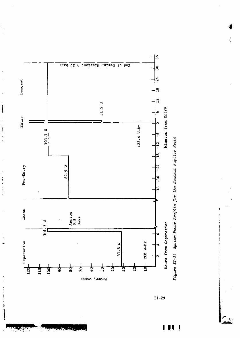
11-12 System Power Profile for the Nominal JupiterProbe ......................... 11-29
11-13 Con,mmications Functional Diagram ........... II-32
11-14 Data Handling Subsystem, Special Purpose Approach . . . II-34
II-15 Power and Pyrotechnic Subsystems ............ II-3511-16 ACS Block Diagram ................... 11-37
11-17 Jupiter Survivable Probe - Task I
Configuration II .................... 11-39
V
J
- |._ _il j_ -_ ,........... _F__.
1972026176-006

IIo_8 Deflection Propulsion Motor .............. 11-42
11-19 Jupiter Probe Attitude Control System ......... 11-44
11-20 Launch to Descent Thermal History ofthe Nominal Jupiter Probe ............... 11-46
11-21 MOPS Spacecraft/Jupiter Probe Integration ....... 11-48
11-22 Probe-Dedicated Alternati_,e Mission Descrlptlon .... 11-50
11-23 Alternative Jupiter Probe Pressure DescentProfile ........................ TI-55
i 11-24 Data Profile for the Probe-Dedlcated JupiterMission ........................ II-56
11-25 Power Profile for Probe-D_dicated JupiterMission ........................ 11-57
11-26 Alternative Jupiter Probe D_dicated Missinn
C_nfigu_atlon ..................... II-61
II-27 Radiation-Compatible Alternati-e MissionDefinition ...................... II-66
II-28 Probe Definition of Spacecraft-Radlation-Compatible Jupiter Mission .............. II-73
II-29 Saturn Mission Description ............... II-79II-30 Saturn Probe Pressure Descent Profile ......... II-82
II-31 Saturn Probe Configuration ............... II-87
II-32 Alternative Saturn Probe Configuration ......... II-89
II-33 Heat Shield Fraction vs Entry Angle forPlanet Saturn .......... II-91
II-34 Mariner Jupiter Saturn Spacecraft ........... II-95
II-35 Spacecraft Probe Integration Configuration ....... II-9711-36 Uranus Mission Description ............... II-i00
II-37 Uranus Probe Pressure Descent Profile ......... II-104
II-38 Optimization of Trip Time for 1979 Launch toJupiter II-iiiIoeoeleoae61 oJoeeoolel,
11-39 Comparison of Launch Opportunities ........... II-iii •
11-40 Rotation Rate Matching at Planets ........... 11-112
11-41 Comparison of Deflection &V Requirements ........ 11-114
11-42 Maximum Deceleration Comparisons for Jupiter
Saturn, Uranus and Neptune ............... II-i17 iII-43 Descent Times to Various Pressures in Both
Jupiter Model Atmosphere ................ 11-124II-44 Probe Major Assemblies ................. II-130
II-45 Comparison of Thermal Descent Severity forPlanetary Missions Investigated ............ 11-134
11-46 Instantaneous Probe Heat Leak ............. II-135
II-47 Radiation Sensitivity to Latltude ........... II-13711-48 Descent Time for Saturn and Uranus vs
Ballistic Coefficient ................. II-141
11-49 Neptune Mlsslon (JUN 79) ................ II-154
11-50 Neptune Pressure Descent Profile ............ II-156
vl
L...........InlllIIII..............ll
n i u
1972026176-007
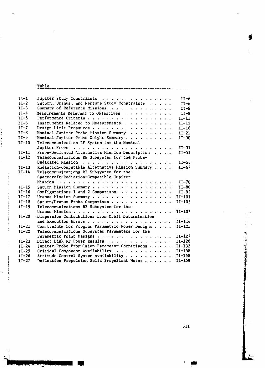
Table
II-i Jupiter Study Constraints ............... 11-611-2 Saturn, Uranus, and Neptune Study Constraints ..... 11-611-3 Summary of Reference Missions ............. 11-8
11-4 Measurements Relevant to Objectives .......... 11-911-5 Performance Criteria .................. II-ii
11-6 Instruments Related to Measurements .......... 11-12
11-7 Design Limit Pressures ................. 11-18
11-8 Nominal Jupiter Probe Mission Summary ......... 11-2111-9 Nominal Jupiter Probe Weight Summary .......... 11-30
; II-i0 Telecommunication RF System for the NominalJupiter Probe ................... 11-31
II-ii Probe-Dedlcated Alternative Mission Description .... 11-51
11-12 Telecommunications RF Subsystem for the Probe-Dedicated Mission ................... 11-58
11-13 Radiation-Compatible Alternative Mission Summary . . . 11-6711-14 Telecommunications RF Subsystem for the
Spacecraft-Radiatlon-Compatible JupiterMission ........................ 11-70
11-15 Saturn Mission Summary ................. 11-80
11-16 Configurations i and 2 Comparison ........... 11-9211-17 Uranus Mission Summary ................. II-i01
11-18 Saturn/Uranus Probe Comparison ............ 11-105
_ ii-19 Telecommunications RF Subsystem for theUranus Mission II 107
ooeoooooo,toooI.,oeoo --
11-20 Dispersion Contributions from Orbit Determinationand Execution Errors ................. 11-116
11-21 Constraints for Program Parametric Power Designs .... 11-125
11-22 Telecommunications Subsystem Parameters for the ,,,_,Parametric Point Designs ................ 11-127 _
11-23 Direct Link RF Power Results .............. 11-128
11-24 Jupiter Probe Propulsion Parameter Comparisons . . . 11-13211-25 Critical Component Availability ........... II-158
11-26 Attitude Control System Availability .......... 11-15811-27 Deflection Propulsion Solid Propellant Motor ...... II-!59
I
vii
r
i m
1972026176-008

I. INTRODUCTION mE
The material in this report summarizes the results of a six-
month study of scientific probes to explore the atmospheres of
Jupiter, Saturn, Uranus, and Neptune to a pressure depth of be-
tween 2 and 30 bars. Included are study constraints, science
and mission objectives, parametric analyses to define require-ments, and definitions of four different probe systems.
The study consisted of five major tasks, shown in Figure I-I
with their relationship to each other. These tasks are (I)define a nominal Jupiter probe system using nominal constraints
of a 1979 Type I mission, -20° entry angle, 5° latitude, 2 Rj
flyby periapsis, etc; (2) evaluate the subsystems defined byreviewing NASA and Air Force programs for component availability,
cost impact, and sensitivity to the environment; (3) use thenominal Jupiter probe as a "reference" for a program parametric
analysis in which the constraints are varied incrementally as
shown by 3a in the figure to define a reasonable set of alter-native Jupiter probe constraints. Use these new constraints to
define two alternative Jupiter probe systems as shown by 3b in
the figure; (4) use data from the Jupiter probe definition to
conduct parametric activity to determine requirements for Saturn,Uranus, and Neptune atmospheric entry as shown by 4a, 4b, and 4cin the figure; and (5) define a Saturn probe with inputs from
Tasks I and 3 and assess the changes necessary to use it at
Uranus as shown by 5a and 5b in the figure.2
To ensure that study results would be as objective as possible,many outside contacts were made with interested scientists.
Martin Marietta has retained a group of consultant scientistsfor assistance in the planetary program studies, and they pro-
vided many helpful suggestions and advice for this study. Theseconsultants include Dr. Richard Goody, Dr. Donald Hunten, Dz.
Michael McElroy, Dr. Robert Vogt, Mr. Harvey Allen Dr. GeorgeWetherill and Dr. Alan Barrett. In addition, outside englneerlng
consultation was obtained in the areas of propulslonj thermal con-
trol, telecomunlcatlons, and power subsystems to determine com-
ponent availability and state-of-the-art technology.
I-I
kl
1972026176-009

REPRODUCIBILITY OF THE ORIGINAL PAGE IS POOR.i
2 { Evaluate
_l Subsystemim__orAv.ll- 1
I "o_o I k_ L ':......'"'"I L_ I'_''_'°_"I I I
_°-,A°...I--'""II I_ I -.)',-,,_I ll-,Lattztud_' • }U° & I'ol.lr
_"...... I v''''_','' _[ I ,,,,T,,_,,_l_ALmoqpherL N, i t_')l/)t'll"lL' _ ,_ , , _t_k_ ,
"_.......... I "o," I [-[_ 1 ',.......:_'_' J I I_l'uriap_l_ T Z kJ -- I 6 RJ
....... [ " " [ J .... ' [ _i P '_I _ ...... _[ b 1 [ ;,::,:,,,,,I_, [--I I Pi....... _ "°P_"r-1
I _ I L /', ..... o,-', I I
[,....._.,,.._J
[: .....'..... ilrL1 _',_', I1[
%.lt_lr q Pr_,ht h_b
1-v,l [u,lt_ i _Ii_,l_ l,,r
hi l'.l flU%
t_lr At m,_s (JL'- / _)III Intrv -
t .......... 1 _' ...... i '"/• J_ 77 **It', /U
AS -_1 I .JhI' ,'7 1[_, _U
Sa+_,nv _*x_t'pt
I} _ Isl' 18 _l \ 4|-_I2
k.valu,lt_' L SL% 8.'-Bl _L'N 84
knt ry -.Neptun= _*
Y;u_:'_ ,'-I ,'t_d4_ _",_o; _J'_._t_ _, _nd y_.vt: LY._U,_'_
~
L
1972026176-010

LvJ
II
II. SUMMARY
the study showed that a Type I Jupiter dedicated mission in 1979 I
with a nominal set of _ission constraints such as a -20 ° entry
angle, 5° latitude and periapsis radius of 2Rj implies a probe
with an ejected weight of approximately 156 kg (344 Ib), an entryballistic coefficient of 102 kg/m 2 and a two-step descent ballis-
tic coefficient of 18 9 kg/m 2 and 213.6 kg/m2 to meet the science
measurement =riterla. In addition, a Jupiter probe-dedicated mis-sion in which the spacecraft performs the deflection maneuver for
: a -15 ° entry ang)e, 30° latitude, and a flyby per_apsis radius of
2Rj, implies a less complex probe than the one above and has an _
ejected weight of approximately 127 kg (2.80 ib) and satisfies the
science measurement requirements with only 13 bars depth of pen-
etration into a cool/dense atmosphere. Compared with this probe-
dedicated configuration, the study also showed that a Jupiter
spacecraft-rsdiation-compatible mission in which the probe per-forms the deflection maneuver, a -15 ° entzy angle, 5° latitude,
and a flyby periapsls radius of 6Rj implies a probe of approxi-
mately 166 kg (365 ib) to meet the science measurement require-ments.
The study also showed that a Saturn probe for a high inclination
JS 77 mission for Titan encounter with -25 ° eutry angle and a fly-
by periapsis radius of 2.33 RS implies a probe with an ejected
weight of approximately i15 k_ (253 Ib) and satisfies the sciencemeasurement requirements at a maximum depth of 7 bars with a de-scent ballistic coefficient of I00 ks/m 2. In addition, a com_,.r_ _ J"
, probe for use at Saturn or Uranus was feasible with a weight pen-
alty of approximately 2 kg to the Saturn probe.
The study is summarized in this chapter which is organized to pre- ..sent first the general mission considerations and science prospec-
tus, which are of a general nature that applies to several or all
planetary appllcationa. These two major topics are followed bythe five probe system definitions: (i) nominal Jupiter probe sys-
tem, (2) Jupiter probe-dedicated alternative probe system, (3)
Jupiter spacecraft radlatlon-compatlble al=ernative _Lobe system,
(4) Saturn probe system, and (5) Saturn probe applicability forUranus. These definitions are followed by the parametric analysissummary for mission analysis of a general nature, then coverspecific parametric analysis for Jupiter, Sdturn, Uranus and Nep-tune. Finally, _hls summary discusses the program from the hard-ware availabillty viewpoint and then fron tho ssvect of commonality.
11-1
iitI
..... ' ..... I I=-
1972026176-011

A. MISSION DESIGN CONSIDERATIONS
The purpose of this section is to describe the implementation of
the science goals and requirements through the design of the mis-
sion from launch to probe entry and descent. It consists of two
main trpics: (i) the general profile of a typical probe mission
to demonstrate the relationships between the various phases of the
mission; (2) an overview of the different missions and constraints
considered in the study.
i. Mission Irofile
a. Launch - The probe mission begins with a launch from the East-
ern Test Range at Cape Kennedy. The prime launch vehicle is the
Titan IIIE/5-Segment Centaur with Burner II. Spacecraft include
the pioneer spacecraft or a Mariner class spacecraft. The Pioneer
is spln-stabillzed and weighs 248 kg. The Mariner vehicle is
three-axis stabilized and weighs 500 kg. The spacecraft is launch-
ed into a 185 km parking orbit and after a short coast is injected
on the interplanetary trajectory.
b. D_netul_y Approach - After the interplanetary cruise, which
may include a swingby of an intermediate planet or a phase under
solar electric power, the spacecraft approaches the target planet.
Befcre the end of this cruise phase, tracking is initiated for a
final midcourse maneuver that refines the approach trajectory to-ward its desired value. The midcourse maneuver is assumed to oc-
cur 13 days before the deflection maneuver. It Js assumed thatthe execution errors of this mldcourse are smsll and therefore are "
dominated by tracking uncertainties at the tim_ of the maneuver.
The control errors of the spacecraft following the mldcourse are
therefore modeled as resulting solely from those tracking uncer-
tainties. Tracking uncertainties at the various planets have been
investigated for combined Doppler/range tracking, QVLBI (Quasi-
Very Long Baseline interferometry) and optical tracking.
11-2
!
! I i '
1972026176-012

c. Deflection - The deflection maneuver is performed at a rangeof from about 5 to 50 million km from arrival at the target planet.
The deflection maneuver consiqts of three critical tasks: (i) The
probe is separated from the spacecraft and placed oi_a trajectoryintersecting the target entry site; (2) the probe must be oriented
for zero relative angle of attack at entry, (3) the relative geo-metry between the probe and spacecraft must be established for an
effective communication link. These entry conditions are illus-trated in Figure ii-i below.
/ \ • 1/ Pre_eDescent- ,,,_Z(_. OrientedProbe // _O I _ for a = 0
Oriented! 3_I / \
Radius
VREL
of Probe
Entry Attitude (_ = 0) b. Optimal Relay Link Geometry
a. Zero Relative Angle of Attack ',
Ficure II-I Definition of Entry Conditions
As indicated, the optimal relay link geometry has the spacecraft ....
directly above the probe during the probe descent (on the para-chute),
11-3
L•_..-_._-,_ ,--..-r_-- ,.r_.,_................._ I I
1972026176-013

Three distinct modes or operational sequences identified to per-
form this deflection maneuver are shown in Figure II-2 and sum-
marized in the following paragraphs [
Mode 1 Mode 2 Mode 3
Probe Deflection Shared Deflection Spacecraft Deflection
Deflect Probe Deflect Spacecraft Release Spacecraft
Probe Probe Probe
Fi___ II-2 Compam_8on of Def_eot_on Mode8
i) Mode i (Probe Deflection) - The spacecraft releases the probe
in the attitude required for deflection AV. After applying the AV
the probe reorients itself to the attitude required for zero angle
of attack at entry.
2) Mode 2 (Sha£ed Deflection) - The spacecraft releases the probe
in the proper attitude for zero angle of attack at entry. The
probe fires a &V in that direction so it is deflected to the
entry site. The spacecraft then accelerates to achieve re-
quired communications geometry at entry.
3) Mode 3 (Spacecraft Oeflection) - The spacecraft trajectory is
targeted to impact the entry site. The spacecraft releases
the probe in the proper attitude for zero angle of attack.
The spacecraft then orients itself and fires a AV to establish
desired flyby trajectory and communications geometry,
Thus, the first mode requires the most complicated probe. It must
be capable of providing the deflection AV as well as the preces-
sion and ACS maneuvers. The requirements for probe precession andACS maneuvers are removed in the second mode, The third mode re-
sults in the simplest probe because nominally all three require-
ments are removed and the full capability of the spacecraft is
exploited. However, some attitude refinement may be required in
tha second and third modes because of tlp-off and spln-up errors.
l
11-4
!
1972026176-014

d. E_'y a_ Descent - After deflection the probe remains dor-
mant for a coast period of 5 to 50 days; then about an hour from
entry, a timer is set off in the probe. The entry batteries are
activated, science instrument warmup is initiated, and spacecraft
acquisition is achieved. Engineering data on the status of the
probe and instruments is then transmitted, Shortly thereafter the
probe enters the planetary atmosphere. The nominal Jupiter probe
pre-entry transmission is terminated at the sensing of 0.i g. The
peak deceleration and maximum dynamic pressure is reached in less
than half a minute after entry. Staging of the aeroshell at Mach
number 0.7 occurs less than a minute and a half after entry.
Following a timed interval from 0.i g, the descent antenna is
activated. As the probe descends through the atmosphere, mea-
surements are taken and transmitted to the spacecraft for relay
to the Earth. The mission ends at pressures of about 10 to 30bars and descent times of about half an hour.
Mission Constraints
The general mission constraints_ mentioned earlier, are summarizedin Tables II-i and II-2. Both tables show the launch w_hicle to
be the Titan IIIE with Centaur and Burner II upper stages. Although
the 5-segment Titan IIIE is emphasized throughout the study due to
the fact that it is being developed For Viking, the 7-segment ve_
hicle has been considered for comparison purposes, The payload
capability for these vehicles is shown ip Figure II-3,
/
Many missions have been analyzed during the course of this study.
Table II-3 lists the missions most often referred to in subsequent
discussions. Missions A, B, C, I and J are the system design mis-
sions described fully in Chapter II, Sections C through G. Missions
D, E, and F are Jupiter probe-dedicated missions, similar to Mis-
sion A, but launched in different years, studied to determine the
impact of launch year. Mission G is an "optimal" Jupiter orbiter
mission, analyzed for the problems introduced by including a probe
on an orbiter mission. Mission H is a low inclination approach
trajectory consistent with a JS 77 mission, All of the data listed
in Table II-3 refers to the nominal design of the specific mission,
In many cases, parametric studies were made about this nominal de-
sign; thus, in certain sections, mission parameters will differ
from those given in the table.
A detailed discussion of general mission considerations is found
in Volume II, Chapter IV and includes mission profiles, launch an_
interplanetary trajectories, approach orbit determination, planetary
encounter, dispersion analysis, planetary entry, and missions to
other planets.
£1-5
1972026176-015

Table Ii-1 Jupiter Swdy Constraints
Constraint Nominal AiLernative
Mission Type I, 1979 Type I, 78, 80-81. 81.-82
Periapsis Radius 2 Rj 6 to 7 Rj
Deflection Mode Probe Bus for Pioneer and MOPS; shared for Pio-neer only
Communciation Mode Relay Direct
Entry Flight Path Angle -20 ° -i0°; -30 °
Entry Latitude 5° 30°; Polar
Atmosphere Cool/Dense _Cool/Dense entry and nominal descent; nom-inal entry and nominal descent
Deceleration Criteria to M < i ibove i00 mb
Descent Depth _ to 30 bars I 2 to 30 bars
Spacecraft MOPS Pioneer; Mariner Family
CARRIER operational Mode Flyby Orbiter
Launch Vehicle Titan IIIE with Centaur and Burner IIi
Table II-2 Sat_zrn, Uranus, and Neptune Study Constraints
Constraint Saturn I Uranus Neptune
Mission Type I, JS 77, I Type I, JUN 79 Type I, JUN 79JST 77, JSP 78, JU 79, SUN 80 SUN 80
SUN 81-82, SUN Sb"N81-82 SUN 81-8282-83, SUN 84 SUN 82-83 SUN 82-83
SUN 84 SUN 84
Deflection Mode Probe Probe Probe
-. Communication Mode Relay Relay RelayEntry Flight Path Angle -I0" to -30 ° <-45" -i0" to -30 °Atmosphere Nominal Nominal Nominal
Deceleration Criteria To Mach <__1 abovs lO0 mbDepth of Descent 2 to 30 bars 2 to 30 bars 2 to 30 bars
Spacecraft Mariner Mariner MarinerCarrier Operational Mode Flyby Flyby FlybyLaunch Vehicle Titan IIIE with Centaur and Burner II
i &
II-6
, J,
1972026176-016

'_ ,,-,4
oON
"' 'J A,-4 •
!:'_ 'll !
! _!]] !r_.M
. _ _
'i/)'I/Ir',_ _ !
If7 i "% o
L, ,-.I
lJi I = ° _'°°/ i' °- °_...... u-- _
4/,I " -;-_'_ ---_-- _-- H
't'.. _
// ..,.4 _D
0 0 O' _ 0 0 0 I
[ I I I I I I i
° ° !i ° ° °_ 0 0 0 0
._ _ _ o ,o _ <_°PVOI._ed
l
II-7
1972026176-017


B. SCIENCE PROSPECTUS
The basic science questions that the nominal probe missio: will
attempt to answer were taken from the previous study (Ref 2) which
referenced a JPL document (Ref 3), and are_
i) What are the relative abundances of hydrogen, deuterium, helium,
neon, and other elements, and what are their isotopic compo-sitions?
2) What are the present-day atmospheric composition and altitude
profiles of pressure_ temperaturep and density, and what effectdo they have on the radiation balance?
3) What are the chemical composition and vertical distribution ofthe clouds?
4) What is the level of turbulence in the atmosphere?
From these questions, measurements to provide answers can be de-fined, and are given in Table 11-4.
Table II-4 Measurements Relevant to Objectives
i. Determine the relative abundances of H and He in the lower ,
atmosphere (below the turbopause)
2. Determine the isotopic ratios H/D, He3/He _, Ne20/Ne 22, C12/
C13, A36/A 40 and others in the lower atmosphere.
3. Determine the concentration profiles of the minor atmospheric
constituentsp particularly Ne, A, CH3, CH4_ NH 3, and H20 ,down to the design limit.
4. Determine the temperature versus pressure and time profilesfrom above the cloud tops down to the design limit with
precision sufficient to ascertain whether the lapse rate isadiabatic.
5. Determine the atmospheric mean molecular weight and identifythe major contributing gasses.
6. Obtain an indication of the vertical distribution and structure
of the cloud layers with respect to pressure and temperature,
and the chemical composition of each layer.
7. Obtain an indication of the magnitude and frequency of any
atmospheric turbulence from above the cloud tops down to the
design limit.
II-9
1972026176-019

In general, there _s no exact one-to-one correspondence between
the questions and observable measurements. Some questions re-
quire many kinds of measurements, while a single measurement maycontribute to several questions. The questions themselves are
strongly interrelated and an answer to one requires at least a par-tial answer to others. The first four measurements listed in the
table are those that determine the bulk composition and general at_
mospherlc properties. Each of these can be measured by one of the
SAG Exploratory instruments without additional data reduction, and
thus are the primary measurements. The fifth measurement, that ofdetermining the mean molecular weight of the bulk atmosphere, can
be accomplished primarily from mass spectrometer data with assist-
ance from the other instruments, and is also a primary measurement.
The last two measurements cannot be directly made by any of the
Exploratory pay-load instruments, but indications can be obtained
by all the instruments; thus these are considered secondary.
The science instrument payload was specified at the beginning of
the study to be the SAG Exploratory payload consisting of four
instrument types; a neutral mass spectrometer, temperature gage,
pressure gage, and accelerometer triad (Ref i). The primary sci-ence activities during the course of the study were (1) to estab-
lish measurements and performance criteria consistent with this
payload, based upon data from the previous study (Ref 2) and dis-cussions with consulting scientists; (2) to provide specific in-
strument characteristics to subsystem areas and to establish the 'word content of each instrument measurement and interface with
the data handling system; (3) to determine the descent profilesand instrument sequencing and evaluate the measurement performancewith respect to the criteria.
For the relevant measurements to be useful for mission design and
evaluation, criteria must be established with which the instrument
performance can be compared to assure that the particular designwill satisfy the objectives. Both depth of penetration (pressure)
and number of measurements are important. Table II-5 presentsthe established criteria for each measurement. These criteria
were influenced by the previous study (Ref 2), the JPL Assessment !- _ Report (Ref 4), and discussions with a panel of science consultants
which included Dr. Richard Goody_ Dr. Donald Hunten, Dr. Michael
McElroy, Dr. Robert Vogt, Mr, Harvey Allen, Dr. 6eorge Wetherill i
i and Dr. Alan Barrett.i
II-lO
1972026176-020

Table II-5 Performance Criteria
i
Minimum
Measurement Pressure Depth Sampling Required
H/He Ratio 1 bar Minimum 4 Measurements at Dif-ferent Pressures
Isotopic Ratios 1 bar Minimum 4 Measurements at Dif-ferent Pressures
_linor Constituents To Design Limit 2 per Scale Height be-, low Cloud Tops
Temperature To Design Limit i per °K
Pressure To Design Limit 2 per Kilometer below
Cloud T6ps
Mean Molecular Weight 5 bars Minimum 4 Measurements at Dif-ferent Pressures
Cloud Layering To Design Limit 2 Measurements InsideEach Cloud
Turbulence To DeEign Limit 1 per Kilometer below
Cloud Tops
The entry site on the planet should be selected so that it is bothrelevant to the desired objectives and typical of the planet as
a whole, in order to permit extrapolation of the results to otherlocations. The lack of optical or ionospheric instruments sim- spllfies the landing site selection considerations for all of the
outer planets, making lightside or darkside entries essentially
equivalent, with the exception of Uranus, which has its pole point-
ing toward the Sun so that all solar energy is input into onehemisphere. It is desirable to enter at least 20° into the Sun
side of the planet from the terminator. It would also be unac-
ceptable, for any planet, to enter close to the terminator because
the processes occuring here may cause atmospheric variations that
the instruments could not separate from normal conditions. Thus,a corridor 6° wide centered on the terminator should be avoided.
Note that this restriction is overruled for Uranus by the 20" mask
angle, because there is a large differential in atmospheric con-ditions between the light and dark side which is not curtailed by
planetary rotation. Also, for Jupiter, it would be desirable _o
avoid shear layers and very high velocity turbulence by enteringat a quiescent site.
Table II-6 shows the relationship of the SAC Exploratory instru-ments to the measurements they are required to make, indicatingwhether the measurement is indirect or direct.
II-ll
1972026176-021

qJ
_o__ w
q t
0
, , , |
II-12
J
-%
, , , III
m
1972026176-022

The accelerometers function both during entry and descant, That
used on both Viking and PArT is the Bell Aerospace Model IX Sys-
tem which consists of one longitudinal and two cross-axis pendu-
lous, force rebalance acceleration transducers accompanied by an
analog--to-dlgltal converter. To obtain a range of 10-2 g to 1600
g requires only a small modification in the flexure of the pendulousproof mass and with new use,J of hybrid microelectronics, the pack-
age will be no larger than that being used for Viking. The algltal
accelerometer system used in this study consists of four partsl
the analog accelerometer_ pulse rate converter, onboard processor,
and an entry g sensor, all packaged in two separate components.
During the entr- phase of the mission, the accelerometers must
measure the entry g-load with sufficient accuracy to enable re-
construction of the g-load versus time curve especially at the
peak g point. From this, the atmospheric structure can be de-termined. The axial accelerometer is sampling at a rate of be-
tween 5 and I0 samples/sec while the lateral accelerometers are
sampling at a raze exactly half of each of these.
i After the parachute is deployed, a signal is sent to the acceler-ometer processor to instruct it to switch the measurement mode
to descent_ simultaneously with the deployment of the temperature
gage. During the descent phasep the objective of the accelerometer ',
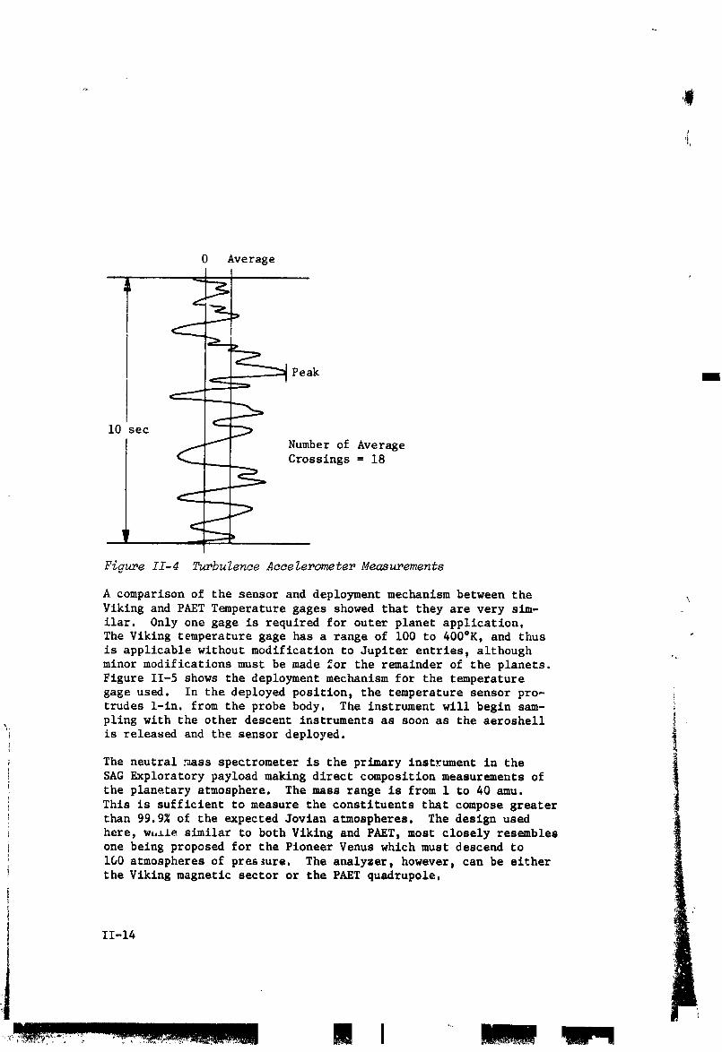
is to determine the magnitude and frequency of the prob responseto turbulence variations. This is done by making an analog sweep •
of 8 to 15 sac duration and using onboard processing to determine
the average value of turbulence, the peak value of t_rbulence, and
the number of average crossings. This is schematically picturedin Figure II-4. This technique is used for the axial accel=rometerand a combination of the two lateral accelerometers so that the re-
sult is a separate measurement of vertical and horizontal turbul-ence.
Both the Viking pressure gage and the PAET pressure rage were con-
sidered for use as a source that could be modified for the entry
probe. The PAET instrument is sllghtly lighter in welgh& but sig-nificantly _naller in volume, which translates into a savings in
supporting system wei_ht. Two PAET-type vibrating diaphragm in-struments are required to cover the pressure range under considsr-ation; one has a range from a few millibars to about 1 bar and thesecond covers the range from this point down to the design pres-sure limit. The inlets are short and exit the probe body parpan- _"dicular to the body and approximately perpendicular to the flow I
streamline, i. _
11-13 __
1972026176-023
0 Average
!
Peak B
i0 sec
Number of Average
Crossings = 18
Figure II-4 Turbulence Accelerometer Measurements
A comparison of the sensor and deployment mechanism between theYiking and PAET Temperature gages showed that they are very sim-
ilar. 0nly one gage is required for outer planet application,The Viking temperature gage has a range of i00 to 400°K, and thus
is applicable without modification to Jupiter entriesp although _minor modifications must be made for the remainder of the planets.
Figure 11-5 shows the deployment mechanism for the temperature
gage used. In the deployed position, the temperature sensor pro-trudes 1-in. from the probe body. The instrument will begin sam-pling with the other descent instruments as soon as the aeroshell
is released and the sensor deployed.
The neutral mass spectrometer is the primary instrument in the
SAG Exploratory payload making direct composition measurements ofthe planetary atmosphere. The mass ran@e is from 1 to 40 amu.
This is sufficient to measure the constituents that compose greaterthan 99.9% of the expected Jovian atmospheres. The design used
here, wt,lle similar to both Viking and PAET, most closely resembles
one being proposed for the Pioneer Venus which must descend to
i00 atmospheres of pres3ure. The analyzer, however, can be eitheri the Viking magnetic sector or the PAET quadrupole,
11-14
1972026176-024

,f
-- Pyrotechnic Device
--_, / ,
Electronlcs and/---Micro Switch
i *
Spring• & Housing
_-Thermocouple Leads"--'l
_Y///////////A_/////////_._,
Piston ---------I 1 L _ I
D>3
Plug Deployed,
_gure II-5 Viking Temperature Gage
Q
II-15
..,. . ....... I I I III II_Imll
1972026176-025

m
The inlet system is of the remote sampling design, which uses
three porous sintered leaks and an evacuated ballast volume (Fig,
11-6) to control the pressure of the sample volume and consequently,the flow into the analyzer. The magnetic sector instrument is a
double focusing type with an electrostatic analyzer that providesboth energy filtering and spatial focusing. The mass separation
is brought about by the magnetic field as in a conventional mass
spectrometer. The quadrupole analyzer consists of four parallel
cylindrically hyperbolic electrodes upon which adc voltage andRF field are superimposed. Mass scanning is accomplished by vary-
ing the field applied to the rods The analyzer section of either
mass spectrometer is state of the art and available, The inlet
system requires further test and evaluation to verify the design,
The response time between gas entering the first leak from the
ambient atmosphere and the analyzer is about 30 sec, with goodpossibility of obtaining < i0, sec. by reducing the sample volume
to the order of 0.1 cm3. Howeverp a problem exists because of the
masses of the primary constituents existing in two different groups,specifically 1-4 amu and 15-18 amu. The leak rates through the
sintered plug could be appreciably different, distorting the mea-surements.
A laboratory model of this proposed inlet system has been built
and tested at Martin Marietta in Earth atmosphere under pressure,
and will soon undergo tests in a simulated Venus atmosphere, Sev_ L
eral laboratory experiments have been identified by this studywhich need to be performed to aid in understanding the application
of this system to the Jovian atmospheres. In particular_ they aret(i) determination of the extent of mass discrimination by the mol-
ecular inlet leak through the analysis of known amounts of two
gases with widely separated masses, (e.g. H2 and N2) with consid-eration of the effect of variations in inlet system temperature;
(2) understanding of the condensation problem in the inlet system
by analysis of a gas with high concentrations of ammonia and/or
water at different temperatures; (3) investigation of the pumpingproblems associated with the high concentration of inert helium in
the Jovian atmospheres; (4) complete analysis of a simulated Jovian
atmosphere containing H2, He, NH3, CH4, and H20. !
The sequence of science events for all of the entry probe missions 1is approximately the same, with the times and pressures for oc-curences varying. The instruments are turned on at least 5 min
before entry for warmup, with time increments due to trajectoryuncertainties added to this. The accelerometers immediately be-
gin sampling data but will not begin storing the 4eceleration data
from all three ages until a g sensor associated with the acceler-ometer processor senses the beginning of entry.
11-i6
1972026176-026

On the missions investigated, entry varies from 19 to 79 seconds,
te_inating when the probe reaches Mach 0.7. This occurs at a
pressure level of from 33 to 92 millibars in the design missions.
At this poin_ the main parac_te is deployed to slow the vehicle
to terminal velocity. After a 12-sec delay during which the aero-
shell is released, the descent measur_ents begin as the pyro-
technics deploy the t_perature gage, first ejecting the plug, un-
covering the mass spectrometer inlet aperture releasing the vacuum.The accelerometers are switched from the entry to the turbulence
measur_ent mode and the full set of descent measur_ents begins,$
at a pressure range from about 40 to 120 millibars. These events
, are preprogr_ed and science data is stored because the space-craft has not yet acquired the probe.
i
Atmos _here
_Porous Leak - PlacesInlet 2
I Variable Leak
Sample i _ '
Fi_e II-6 _ss _ec_eter _let _st_
i
II-17
I il
1972026176-027

For descents into Saturn, Uranus, and Neptune, _uch higher bal-
listic coefficients are required than for Jupiter, For these mis-sions, after a delay of about an additional 3 sec, the main para-
chute is released and a secondary parachute is deployed. Allfour instruments for all missions collect data in the descent mode
and store it with the entry accelerometer data. After approximately
90 sec, the spacecraft acquires the probe and data transmission
begins, sending all the data subsequently collected back in real
time and interleaving the stored data.
The descent parametrics for each planet, including selection of
' ballistic coefficients and instruments sampling times are detailedin subsequent chapters. To meet the instrument performance cri-
teria , three distinct points in the descent are critical.
i) Descent where the temperature begins to increase, generally
2 to 4 mln after chute deployment;
2) the first encounter of cloudsp which varies from 2 to 8 minafter deployment;
3) _ediately after drogue chute deployment, when this occurs.
The design limit pressure is that point in a descent profile where
all of the requirements, within an overall set of constraints,
have been met by the actual performance. In this study, this over- ,,all constraint was to descend to 2 to 30 bars depending upon the
"risk and cost effect" of the higher press_.res. Actual end ofmission varies from 7 to 30 bars.
The measurement that controls the depth is that of determining
the composition of the lovest (above 30 bars) cloud in the given
atmosphere with the mass spectrometer. The specific requirementis to obtain two full mass spectrometer sweeps inside the cloud.
The design limit pressures that were determined in this study areshown in Table II-7°
Table II-? DesiEn Limit Pressures
; Atmgsphe r Cloud Pressure J bars i
Jupiter, C/D H20 13 i
Jupiter, Nom H20 7.5 iSaturn, Nom H20 7
Uranus, Nom NH3 7Nepture, Nom NH3 20
i 'If-18
1972026176-028

C. NOMINAL JUPITER PROBE SYSTEM DEFINITION SUM>_RY
The constraints for this configuration follow.
Mission Type I, in 1979
Entry Angle -20 °
Entry Latitude 5 °
Depth of Descent and 30 bars in a cool/dense atmosphere
Atmosphere
Science SAG Exploratory playload (Viking)
Spacecraft TOPS
Carrier Mode Flyby
Periapsis Radius 2 Rj
Communication Mode Relay
Deflection Mode Probe
Ejection Radius 10xl06 km
Entry Ballistic Coefficient 0.65 slug/ft2(102 kg/m 2)
Descent Ballistic Coefficient 0.12 slug/ft2(19 kg/m 2)
and 1.5 slug/ft2(236 kg/m 2)
i. Mission Definition
The Nominal Jupiter Probe Mission is described in Figure II-7 and
detailed in Table II-8. Important mission design results are sum-marized in this section.
a. Interplanet_ry Trajectory Selection - The interplanetary tra-
Jectory is pictured in Figure ll-7(a) with lO0-day intezvals noted.
The launch date of November 7, 1979 and arrival date of September
17, 1981 (trip time of 680 days) result in a maximization of the
payload weight as discussed in Volume II, Chapter IV, Section A.
As indicated in the figure, the spacecraft arrives at Jupiter
shortly before the view to Jupiter is obstructed by the Sun.
II-19
! I
]972026]76-029

11-20
II I!II
'1072020'170-030

Table II-8 Nominal Jupiter Probe Mission Sw.mary
a. Conic Trajectory Data
Int=rplanetary Trajectory Launch Trajectory Arrival Trajectory
Launch Date: 11/7/79 Nominal C3: 93.6 km2/sec 2 VHP: 8.474 km/secArrival Date: 9/17/81 Nominal DLA: 30.5° RA: 161.3 °
Flight Time: 680 days Launch Window: 1 17 hr DEC: 6.81 oCentral Angle: 155 ° Parking Orbit Coast: 36 min ZAE: 145.2 o
C 3 (iO day): 97.5 km2/se¢ 2 ZAP: 14! A°
C 3 (20 day): 105 k/n2/sec2 RP: 2 RjAzimuth Range: 101.7 o - 115 °
INC: i0°
b. Deflection Maneuver and Probe Conic
: Deflection Maneuver Probe Conic Definition
Deflection Mode: Probe Entry Angle: -20 °
Deflection Radius: "i0 x 106 km Entry Latitude: 5.0Coast Time: 9.75 days Entry Longitude: 88.9AV: 221 m/set Lead Time: 45.8 min
Application Angle: 116° Lead Angle: -12.05 °
Out-of-Plane Angle: 0° Probe-Spacecraft Range (Entry): 96,742 kmRotation for Probe Release: 810 Probe Aspect Angle (Entry): 43.9 °Probe Reorlentation Angle: -53 _ Probe Aspect Angle (Descent): 21.0 °
Spacecraft AV from Earth: NA Probe Aspect Angle (EOM): 4.7 °
c. Dispersion Analysis Summary
Naviation Uncertainties Execution Error_ (3:) ! Dispersions (3=)
Type: Range-Doppler 167-day arc .'.VProportionality: 1% Entry Angle: i.i °SMAA: 1482 [an iV Pointing: _o Angle of Attack: 2.5 °
SMIA: 139 km Probe Orientatiol, Pointing: 2° Down Range: 2.02° 2_: 88° Cross Range: 0.80 °TOF: 54 sec Lead Angle: 4.4 °
Lead Time: 7.4 minEntry Time: 8.0 min
d. Entry and Descent Trajectory Summary
% Critical Events
Altitudes
Entry Parameters Descent Parameters Time from Entry above 1 arm
Entry Velocity, kmlsec: 60 Descent Atmosphere: g = 0.I, sec: 6.0 km: 182Entry Altltude, km: 304.6 Cool/Dense Max g, sec: 12 km: 65
Entry B, slug/ftl: 0.65 EOM Pressure, bar: 30 H - 0.7, sec: 34 km: 32
kg/m2: 102.1 Descent B, slug/it2: Descent rime, mln:Entry Atmosphere: slug/frY: 0.12 33.3
Cool/Dense kg/m2: 18.84 EOM, min: 33.8 km: -85
Max Deceleration, g: 1500
Max Dynamic Pressure,Ib/ft2: 2.1 x I0 _
kg/m2: 1.0 x I06 ..j
II-21
/
I [I !m! 111 I
1972026176-0:31

b. Launch Analysis - The launch analysis is provided in Figure
II-7(c). Available payload is plotted against launch period for
three sets of launch vehicle performance data: standard data for
the Titan 5-Segment vehicle with and without Burner II plus up-
dated data for the Burner II. For reference, the payload weight
(probe, spacecraft, spacecraft modifications, and spacecraft-
launch vehicle adaptor) is about 454 kg (I000 ib) for a Pioneermission and 680 kg (1500 ib) for a MOPS mission. Thus, the Burner
II option is necessary for a MOPS-type mission to obtain a 20-day
, launch period. The nominal launch trajectory summarized in Table
ll-8(a) indicates that the daily launch window and parking orbit
: coast time are satisfactory.
c. Approach Trajectory - The approach trajectory is pictured in
Figure ll-7(d) and summarized in Table ll-8(a). The spacecraft
trajectory was selected with a periapsis radius of 2 Rj to obtain
a good communication geometry between the probe and spacecraftduring the probe descent phase. The inclination of I0°, with
respect to the orbital plane of Jupiter, was chosen so that the
probe entry site defined by a latitude of 5° and an entry angleof -20° could be achieved with an in-plane deflection. The com-
munication geometry chosen has a lead angle of -12.05 °, probe
lea4ing spacecraft at entry, so that the probe aspect angle at
the start of descent is 21°, passes through zero during descent,and is 5° at the end of the mission (EOM).
d. Deflection Maneuver - The probe deflection mode was used forthe deflection maneuver for this mission. The deflection maneuver
is illustrated in Figure II-7(c) and summarized in Table ll-8(b).The deflection radius of i0 million km resulted in a AV of 221
m/set and a coast time (time from deflection to probe entry) of
9.8 days. The AV is applied at an angle of i16° to the approach
asymptote and is in the plane of the spacecraft trajectory. The
spacecraft must rotate 81° from its Earth-lock attitude to release
the probe. After firing the AV, the probe must precess 53° toobtain the attitude required for zero relative angle of attack.
e. Dispersion Analysis - The .lavigation and dispersion analysisresults are summarized in _able II-8(c). The navigation uncer-
tainties have little impact on dispersions at entry, even assum-
ing only a standard range and Doppler tracking arc. All the
entry parameter dispersions are within satisfactory tolerances.
The communication parameter dispersions are discussed in the tele-communication subsection.
t
i II-22
1972026176-032

#I
,Jlr
f. Entry and Descent Trajectories - Table ll-8(d) summarizes
the entry and descent phases of the mission. The cool/dense
atmosphere model is used for both phases of this mission. The
entry phase starts at 304.6 km above the 1 arm pressure level
(0 km alt - 71,726 kin) and ends at the staging of the aeroshell
34 sec later. During thi,._phase, the peak decelcr.ation of 1500
g is attained. The descent phase starts after staging and lasts
until the end of the mission at 30 bars. The total mission time
(entry and descent) is 33.8 rain.
2. Science":
Many of the mission characteristics of the nominal Jupiter probe
were specified by the statement of work. The science instruments
were specified to be Vlking-derived wherever possible. The tem-
perature gage is the Viking parachute phase instrument; its range
of operation is sufficient for the Jupiter probe. Two pressure
transducers are necessary to cover the pressure range required.
One can have a range similar to that of the Viking instrument
(0-300 mb) and the other must have a larger range. The accelerom-
eter triad is the Bell Model IX 3-axis system with pulse rate
convertor, with a modification to scale up the flexure for 1500 g
peak load. The proposed neutral mass spectrometer deviates from
Viking, but is considered to be a magnetic sector analyzed with
a porous leak remote inlet system. The characteristics are com-
patible with Viking derivations. "
The nominal Jupiter probe analysis considered only the cool/dense
atmosphere and the descent profile (Fig. II-8) was chosen with
this assumption. Also, this initial task was to determine what
was necessary for descent to 30 bars. The resulting parameters
that were chosen to be consistent with the criteria are:
Design pressure limit - 30 bars
Main parachute ballistic coefficient - 0.12 slug/it 2 (18.84 kg/m 2)
Drogue parachute ballistic coefficient - 1.50 slug/ft 2 (235.5 kg/m 2)
Separation Pressure - I0 bars
Parachute deployment pressure - 92 millibars
Pressure at first measurement = iii millibars +
Entry Time - 34 sec
II-23
+ L.,_ I' I !llll m
1972026176-033

0.05
ParachuteDeployment
0.1 !
Coel/Dense Atmosphere
"_ 0.5
1.0B- 18.84 kg/m2 (0.12 slug/ft2)
m
Parachute10
30 bars _. (1_ .50
slus/ft2)
50
I0 5 10 15 20 25 30 35 40
Time from Entry, mln
II-24
C.-_.<. -7-- ....."___-"_" "ll I I I
1972026176-034

Descent Time - 33 mln, 6 sec
Instrm_ent Samplin E Times :
T_mperature and Pressure - 5 sec j
Neutral Mass Spectrometer - 50 sec
Entry Accelerometers - 0.1/0.2 sec
Descent Accelerometers - i0 sec
Total bit rate - 28.0 bps
All performance criteria were satisfied.
3. System Integration
Figure 11-9 shows a typical sequence of events pictorlally andshows the relationship between the spacecraft and probe. A de-
tailed sequence was generated for this and all other configura-
tions for the purpose of determining time for acquisition, timesfor various power loads, etc. These _equences are discussed inVolume If.
A typlcal functlon21 block diagram is shown in Figure If-10 for
thls configuration and all others, except for the probe-dedicated
alternative Jupiter mission. For that exception, the p_opulslonsubsystem is deleted and the ACS propulsion is very simple. This
figure shows the relatlonshlp of each subsystem as well as theelectrical interface with the spacecraft before and after the
probe separation.
A data profile and power profile were generated for this and all
other configurations. These are shown in Figures II-ii and 11-12,
respectively. These are similar for all configurations exceptthe probe-dedicated alternative Jupiter probe, which has a very
short separation phase during the time engineering data is notrecorded; therefore, the pewer demand occurs at pre-enery.
A weight summary was generated for this confisurat4on as presentedin Table 11-9.
!
i
II-25 _'
i-4
• I
1972026176-035

i II-26
LI III
1972026176-036

,W
.- _L I I ....I __ 0
_-" _ _ I _ _" _=°_" _ _ I _ _ "_ '
° Im ii|lll|llll IIIIIIIIl_ m _,J
m _
1_o • ii|
r F _
.....................S ............. _ ' __I
"" '='i "== i
8 _< .... , g--_ _i _'_
8_ _ _= ,-_ .--_ _ _ _,_.,-,
, o g
ll|IIllllllIllIllIllllllIlllllIIIIIllllllIl|llI IIIIIIlllIllllIllllllllI|lllllI llIl IllIlllIllllllllllllllliOllIllIllllll|llllll||l_II
I !_ '--': [_ II
| •
, I _ ,
I1-27
L
"197202_'17_-037

L_
_.-_T,_:,I ..........._,._.,.__..,,,:._.... I | !INI II,NI!lll I
1972026176-038
1972026176-039

F
Table II-9 Nominal Jupiter Probe Weight Summary
Probe Breakdown Weight, kg
Science 8.66
Power and Power Conditioning 5.91
Cabling 5.44
Data Handling 2.13
Attitude Control, dry 11.76
Communications 3.61
Pyrotechnics 6.31
Structures and Heat Shield 61.92
Mechanisms 7.71
Thermal 7.44
Propulsion, dry 3.85
Propellant 12.16
Engineering Instrumentation 0.0
15% Margin 20.54
Ejected Weight, kg 157.46
Entry Weight, kg 106.34
Descent Weight, kg 41.93
4. Telecommunications Subsystem - Definition of the telecommunications
subsystem for the nominal Jupiter probe system was linked heavilywith design of the probe trajectory. The mission optimized com-
munication parameters in order to minimize the RF power required.Many changes were made in periapsis radius, lead time, and bal-
listic coefficient in order to arrive at a trajectory that placesthe spacecraft overhead at the end of the mission and minimize
several RF power sensitive parameters. The objective was to have
minimum communications range and probe aspect angle at missioncompletion.
The subsystem characteristics are summarized in Table II-i0 and a
functional block diagram is shown in Figure 11-13.
11-30
1972026176-040

i
Table II-10 Telecommunications RF Subsystem for the Nominal Jupiter Probe
CONDITIONS: Planet:Jupiter S/C: TOPS FREQUENCY: 1GHz BIT RATE: 28 bps
COMPONENT CHARACTERISTIC UNIT VALUE
Transmitter RF Power Out W 25
Overall Efficiency % 45DC Power in at 28 V dc W 55
Total Weight Kg 2.7ib 6.0
RF Switch Type MechanicalInsertion Loss dB 0.3
i Weight kg 0.23: l ib 0.5
Entry Antenna Type Spiral on ConeMain _eam Angle deg 55
Beamwidth dee 35
I Maximum Gain dB 6.2Size (i x diameter) cm 27 x 22.5
in. 10.6 x 8.8
Weight kg 0.45ib 1.0
Descent Antenna I Type Turnstile in CupI Main Beam Angle deg 0
Beamwidth deg 110i Maximum Gain dB 5.2
Size (diameter x h) cm 18.8 x 7.6in. 7.4x3.0
i Weight kg 0.23Ib o.50 ,,
Spacecraft Antenna i Type Helix
Beamwidth deg 45Maximum Gain dB 12.3 •Size (I x di meter) cm 51 x 9.5
in. 20 x 3.75
Weight k8 2.27ib 5
Despln NoPosition Search sec 1
Frequency Acquisition deg 35Clock Angle, O deg -94
Cone Angle, _ deg I00
Spacecraft Receiver Noise Temperature °K 300
Noise Figure dB 3.1DC Power in at 28 V dc W 3.0Weight kg 0.9
Ib 2.0
II-31
...... ..... I I !lm I!
1972026176-041

t
Jl,
I I I I III!
1972026176-042

5. Data Handling Subsystem
The selected configuration (Fig. I!-14) is a special purpose DHS
that contains those functions which are necessarily centralizedand must be retained in the common subsystem. These functions
consist of synchronization, sequencing, and formatting. In addi-
tion to the low capacity buffer memories required for formatting,
a science data storage memory is included primarily for entrydeceleration data. The design size and weight are based on bi-
polar IC electronics, hybrids, and standar_ piece parts. A dis-cussion of the design configuration details is contained in
Volume II, Chapter V, Section B.5; and integrated discussion of
data handling alternatives is contained in Vol III, Appendix H.
The physical characteristics were based on estimates of the num-
ber of devices required for each function. These estimates re-
sulted in the following physical characteristics: volume 142 in.3;
weight 4.7 ib; and power 6.9 watts. The weight of the memory wasbased on an estimate from Electronic Memories (Division of Elec-
tronic Memories and Magnetics Corporation). The estimate for a
7 kb bipolar IC memory (8 kb card) is volume 6.5x4.5x0.25 in.,weight 0.5 ib, power 6 watts. This has been used as a basic build-
ing block for the cost of memory capacity. The resultant total
weight for the nominal Jupiter probe DHS and memory is: voEume158 in.3; weight 5.7 lb; and power 18.9 watts.
6. Power and Pyrotechnic Subsystem
The subsystem (Fig. 11-15) is div[ded to two sections: (i) the
post-separation subsystem which consists of a central power con-
ditloning unit that provides power to attitude precession logic,
thrust control electronics, pyrotechnic data handling and RF sub-
system; and (2) the entry and descent power subsystem which con-sists of power distribution (relays) and Jqolation power filters.
Required power conditioning is implemented in the user subsystem
electronics. Primary power is provided by separate remotely ac-tivated Ag-Zn batteries for post-separatlon and entry/descent
periods. A mercury-zinc battery provides power (40 V) for
capacitor bank charging for the first pyrotechnic battery event.A self-contained Hg-Zn cell provides power for the Accutron coast
timer. Pyrotechnic circuitry is similar to Viking designs and !
estimates are derived from that program. A discussion of the
power and pyrotechnic configuration may be found in Vol II, Chap-
ter V, Section B.6 and Vol III, Appendix G. The physlcal char-
acteristics of the electronics, conversion equipment and filters
are based on similar subsystems and engineering estimate.
II-33
., !nunnl u n!mmnun
1972026176-043

p_
,.,,..... ..... ..... I IIl!!.m " fin
1972026176-044

,,|
Ii-35
I
1972026176-045

Id
The remotel) activated batteries were estimated from the weight
chart in Appendix G with an assumed 13.7 in.3/ib volume. C_pac-itor banks, pyrotechnic relay control and power distribution
(relay) characteristics were based on part count and known volumeand weight of the elements. The physical characteristics of these
subsystems are tabulated. A more complete description of th,se
subsystems may be found in Volume III, Appendix G.
Power Subsystem Size_ in. 3 Weight, ib
Post-Separation Battery 94 6.9
Entry Battery 56 4.1
Hg-Zn Battery 4x2 in. diameter 0.9
Pc_er Conditioning 40 2.0
Power Dis tribution i0 i.0
Pow..r Filters 20 2.0
Pyrotechnic Subsystem
Elec tronics 75 2.0
Relays 91.8 6.6
Capacitor Banks I00 1.85
7. Attitude Control Subsystem
The attitude control subsystem (Fig. II-16) consists of sensors
(solar aspect angle and planet sensor) sector and data processinglogic, cold gas precession and spinup subsystem, and a nutatlon
damper, Solar aspect angle and the angle be_.Teen the Sun and the
planet referred to the probe spin axis are measured. The measure-
ments are processed to develop a precession program which is then
implemented by sector logic control. A period of six hours is
allowed for the maneuver to enable the nutation damper to removeexcessive nutatlo,n during this period. A discussion of the con-
figuration of the ACS is contained in Vol II, Chapter V, Section
B.7, and Vol III, Appendix F.
11-36
r
.....................• |..............................----, .... lie I amiD1! I I
1972026176-046

II-37
1972026176-047

The estimated physical characteristics of the attitude control
subsystem are:
Size, cm3 (in.3) Weisht, ks (ib) Power, watts
Sun Sensor 228 (14) 1.59 (3.5) 2.0
Jupiter Sensor 130 (8_ 0.91 (2.0) 1.0
Electronics 1630 (i00) 1.36 (3.0) 2.0
8. Structures and Mechanical Subsystems
The nominal Jupiter probe consists of a descent probe, an entry
module, a service module, and a deflection maneuver motor. The
descent probe accommodates the scientific instrument complement
and the supporting electrical and electronic components to fulfillthe desired mission. These components are housed within the
descent probe and supported off an equipment support deck which
in turn is thermally isolated from the outer shell. The de_cent
probe is completely encaps1_latec"for planetary entry within a
forward aeroshell/heat sh._id structure and an aft heat shield
cover, providing pro=ection of the descent probe against the
entry heating an_ a_c_dy,Lamic pressures. A service module con-
taining the attitude control system is attached to the af. end of
the entry module to provide attitude stabilization and attitudecontrol of the probe from spacecraft separation until just before
planeLary entry. This unit is expended and ejected from the entry
probe jus_ before planetary entry. A solid propellant rocket
motor attached to the aft _nd of the se_:ice module to provide the
deflection man, _er delta velocity, completes the configuration of
the Jupite- pro . The nominal Jupiter _-obe ia its various mis-
sion pha_..onfigurations is shown in Figu=e II-17. The probe is
0.94 n ( _ im.) in diameter, 0.92 m (36.3 in.) long, weighs
157.5 kg (347.3 ibm) at spacecra£t separation. The length is re-
duced to 0.535 m (21.1 in.) and weight is reduced to 106 kg (234ibm) before entry. The descent probe is 0.483 m (19.0 in.) in
diameter, 0.457 m (18.0 in.) long, and weighs 41.9 kg (92.6 ibm).
The structural design of the nominal Jupiter probe uses all high
3trength aluminum alloy construction. This is possible because ofthe thernal protection provided at e_ry by the surrounding heat
shield both on the nose and on the aft end of t_.eentry probe.
(The aeroshell is assumed to be below 300°F at peak loading.) Theprobe is designed _o withstand the entry deceleration of 1500 g
encountered at e_itryinto the Jovian atmosphere. The aeroshell
of th_ nose cone is designed to w±thstand the peak dynamic pres-sure of approximately i.]3 x ]06 N/m 2 (23500 psf), and is sized to
provide a ballistlc coefflci_nt of 102 kg/m2 (0.65 slug/ft2).
II liFT i ra Ill i "1!11
1972026176-048

t|i-+,tO] DJliql itIII hllO] a Iml_O]t4 t_ I_.,-+_I _'--x_I _liI_O] [II
,i
EOLI:_UT FRAME I -'- I
........'++,,,,+_mm,.'++++_++.+_;34:,,.,.+.,,++.+,+_,;_,.... • .7+.+_,, _ _, ,,>,_,*+._+._,--+•• , ,_ ...., _<,,,,+"',-"¢++,,+_*+,+,> •_',_:,+_,......
1972026176-049

Nql;¢O]e2gLglllqI hnLO]:mI mI_O]_( L_llr-'ll_'.._ I klkO, O];i
FOLDOUT.ERA,ME --,
......... ;_'G'. _ _,,;_)7,..._w_ _ ...... _.:__=._;.._.; _,__ .....
1972026176-050

Nq_le_,O]nblll._11;flnUlllmmO]tll,,,l_Ol_4 Le]l,-_.,_11_.,_.¢"]a kqlie,,O,O):U
I_ ; JFOLDOUT FRAME FOLDC
_u
1972026176-0_

:(I il,¢0]DlwJ.qa;]INII bN,O]_ h Ilnm.O__k .-,_.l b_OiO] _~.
Eig_re II-._? Jupiter Survivable Pro
J FOLDOUTFRAME_/
1972026176-052

Figure II-l? Jupiter Survivable Probe - Task I Configrration II
; II-Z9 and II-40
FOLDOUTFRAMET" ] FOLDOUT FRAMECI
- l!l_,_:,.
1972026176-053

t
This coefficient provides a deceleration of the probe at entry to
a velocity of Mach 0.7 at a pressure altitude of approximately 100millibars, meeting scientific requirements for staging of the
descent probe and the beginning of the descent mission.
The descent probe uses two parachute stages for descent. The
first parachute, deployed at i00 millibars pressure_ is 2.46 m
(7.5 ft) in diameter and provides a descent probe ballistic co-
efficient of 18.9 kg/m2 (0.12 slug/ft2). This ballistic coef-
ficient satisfactorily provides adequate separation force to
pull the descent probe from the aeroshell at staging and the de-
sired initial rate of descent for the descent probe. It is mortar-
deployed using a pyrotechnic energy source, and upon being jet-
tisoned after initial descent, pulls out the secondary parachute
for more rapid descent toward the end of the mission. The second-
ary parachute is quite small, 0.45 m (i.0 ft) in diameter, and
provides a ballistic coefficient for final descent of 236 kg/m2
(1.5 slug/ft2). The entry heat shield uses a high density ATJgraphite ablator on the nose with a carbonaceous backface insulator.
It has a mass fraction of 0.317 (heat shield weight/entry weight).The base cover heat shield uses an ESA 55000M3 ablator to protect
the base of the probe.
9. Propulsion Subsystem
The propulsion subsystem for the nominal Jupiter probe consists ,of a spherical, solid-propellant, rocket motor to provide the re-
quired deflection maneuver delta velocity of 221 m/sec (725 fps).It also consists of a cold gas (nitrogen) attitude control system
providing a spin-despin-precess maneuver. For the attitude con-
trol of the probe after spacecraft separation, this system pro-
vides s spinup of the probe to 10.5 rad/sec (i00 rpm) and then a
precession maneuver through an angle of 0.87 tad (51°). The probe
is despun to 0.52 rad/sec (5 rpm) before entry to provide reduced
attitude stability for planetary entry.
The rocket motor to provide the deflection maneuver is a spherical
solid propellant rocket motor weighing 14.5 kg (32.0 ibm) and con-taining 10.6 kg (23.5 ibm) of propellant. It uses two exhaust
nozzles mounted at 0.78 rad (45°) with respect to each other, pro-
viding protection against impinging the carrier spacecraft with
solid propellant waste products from the motor at probe separation
from the spacecraft. The motor is 0.246 m (9.7 in.) in diameter.
The motor is shown in Figure 11-18.
11-41
,,,,
- m l
1972026176-054

II-42
.! i , i
1g72026176-055

The cold gas attitude control system consists of pairs of 4.4 N
(i.0 ibf) nozzles mounted around the periphery of the entry probe
to provide the required torques for the spin and despin maneuvers.
A single nozzle mounted parallel to the spin axis along the probe
circumference provides for the precession maneuver. _is nozzle
is pulsed for 0.78 rad (45 °) of probe spin, once each revolution,
until the precession is complete. The cold gas propellant re-
quired for the attitude control system is 1.48 kg (3.27 ibm) to
perform the spin-despin-precess maneuver, and finally eject theservice module. The total system weight is 6.67 kg (14.72 ibm).
The schematic of the system is shown in Figure 11-19.
! i0. Thermal Control Subsystems
Thermal control is required to maintain the probe equipment within
acceptable temperature limits throughout all phases of the outer
planet mission. For the nominal Jupiter probe, the thermal de-
sign concept consists of multilayer insulation, thermal coatings
and radioisotope heaters for the spacecraft cruise and probe
coast phases. For the entry and descent portions of the mission,
the probe relies on sufficient thermal inertia and low density
foam insulation protection internal to the probe shell.
The pivotal temperature from a standpoint of thermal design is _he
probe temperature at the end of the mission coast phase. For the
nominal Jupiter probe (cool/dense atmosphere), the primary thermal
problem is one of losing too much thermal energy to the atmospheric '
environment during descent. The probe entry temperature, there-
fore, must be adequate to allow sufficient leeway for probe cool-
ing. Likewise, however, the probe equilibrium temperature during
the long duration spacecraft cruise must be safely below the upper
allowable battery storage limits (Chapter V, Section _.lO.d in
Vol II).
II-43
i
i
1972026176-056

1972026176-057

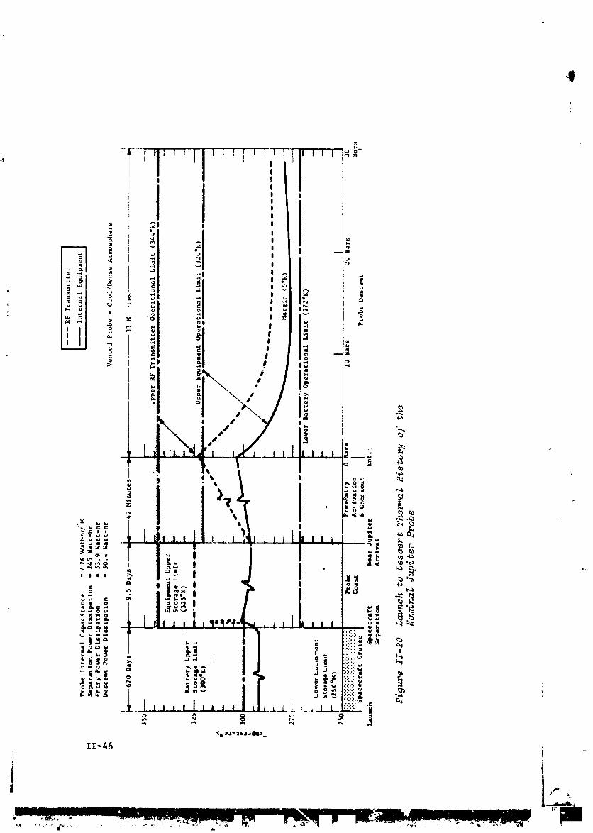
A probe thermal analysis was performed for the defined nominal
Jupit&r probe miJsion. On the basis of these thermal analyses,
a complete thermal history of the nominal Jupiter mission wasconstructed and is presented in Figure II-20. The space,raft
cruise and coast temperatures are determined based on the r_dio-
isotope heater power present and the degree of solar energy ab-
3orption during the coast phase. The probe temperatures r,_-re-
sent the aggregate internal equipment, which includes the sficvice
module during cruise and coast. The RF transmitter is shown sepa-
rately from the probe aggrpgate equipment when activated becauseof its high electrical dissipation and relatl-ely small mass.
The results presented show that the passive thermal design selectedis ad=quate to maintain the probe temperatures within limits. Tra-
Jectory uncertainties for entry are only 7 min for the nominalJupiter mission and contribute to only slight initial descent
probe temperature uncertainty. The biggest uncertainty in the
thermal design is the performance of the multilayer insulation
used to maintain the probe temperature during cruise and coast.Since the radioisotope heater output is constant, and cannot be
changed during the mission, the multilayer insulation performanceand repeatabilit:t will have to be accurately determined by full
scale thermal tests before final design. For descent, the worst-case model atmosphere encountered was considered, and conservative
foam insulation properties were assumed together with optimum
heat transfer free convection inside the probe.\
The Drob_ temrerature margins, predicted on the basis of probe
_hermal analysis for the nominal Jupiter mission are:
SPACEC_%FT PROBE ENTRY-CRUISE COAST DESCENT
TEMPEPA_OREMARGIN PHASE_ °K PHASE_ oK PHA_£_ °K
Above Equipment LowerLimit 42 22 5
Below Equipment UpperLimit 8 23 17
Below Transmitter
Upper Limit NA 28 22
11-45
......:.......... m ................................
-'.,...... ,_- . _- ......... _,_,.,=_,,,_,.,,_._w,_.,,. _._.,_,,.,,_,,,,..., t ..........._ _
1972026176-058
,i

ii. £rcbe to Spacecraft Inte_ratlon i
The integratien of the planetary probe with a carrier spacecraft
was performed using a Martin Marietta modified outer planet space-
J craft (MOPS) as the carrier. _e configuration of the _pacecraft
with the nominal Jupiter probe attached is shown in Figure II-21.
The probe is mounted on the aft end (for launch) of the space-
craft, with the probe heat shield pointed away from the space-
craft, providing the proper probe orientation with respect tothe spacecraft for later separation. The probe interfaces with
the spacecraft in the following categories before separation from
the spacecraft: structures and mechcnical, power, thermal con-trol, instrumentation.
r The probe is attached to the spacecraft through a mechanical
release joint incorporating a matched set of separation springs.! The probe is held ir place by means of attachments incorporating_ explosive nuts, which provide for release.
I The interfaces of the probe with th_ spacecraft are discussed in
i _hapter V, Section B.II of Vol II.
i ,,P
II-47
1972026176-060

Probe Weight| 344 ib Spacecraft Mod (MMC MOPS): 54 ib
Cruise:
Environmental CoverT/C Power - 5 W
Monitor (on Demand)0.5 watts and 80 bits
Preseparation Checkout¢
Power - 8 W Ave; 30 W £eakCheckout SignalsData Monitor - 1400 bits
Separation:
Probe Pointing - 2°
Battery Activation Signal
Separation Signal \
Probe _
Post-Separation:Track Probe
Receive Data - 30 bps;60 to 80Kbits _'_'
Figure Ii-21 MOPS Spacecraft/Jupiter Probe Integration
II-48
1972026176-061

Ii
D. JUPITER PROBE-DEDICATED ALTERNATIVE PROBE SYSTEM DEFINITION
SUMMARY
The constraints for this alternative Jupiter probe were the result
of the Jupiter parametrics discussed in Chapter IZ, Section C.I. In
general, this confisuratioL was intended to optimize the probe byreducing its complexity and the radiation field that it would en-
counter. The Eeneral constraints are:
! Mission Type I in 1979
: Entry Ansle -15" (structure_ desiEned to -20 °)
Entry Latitude 30°
Depth of Descent and 13 bars in cool/dense atmosphereAtmosphere and 7.5 bars in nominal atmosphere
Science SAG exploratory payload (PART)
Spacecraft Mariner Family
Carrier Mode Flyby
Periapsis Radius 2 Rj \
Communication Mode RelayJ
Deflection Mode Spacecraft _,
Ejection Radius 30 x 106 km
Entry Ballistic Coefficient 0.65 slus/ft 2 (102 kE/m2)
Descent Ballistic Coefficient 0.09 sluE/ft 2 (14.1 ks/m 2)
I. Mission Defini_:ion
The probe-dedicated alternative mission is described in FiEure
II-22 and detailed in Table II-ii. Important mission design re-suits are summarized in this section.
II-49
IIIHlililil I 1
lgT2028178-O82

Eli
II-50
|
1972026176-063

Table II-11 Probe-Oedicated Alternative Mission Description
a. Conic Trajectory Data
{
Interplanetary TraJectory Launch Trajectory Arrival Trajectory
Launch Date: 11/7/79 Nominal C3: 93.6 km2/sec 2 VHP: 8.474 km/secArrivtJl Date: 9/17/81 Nominal DLA: 30.5" RAm 161.3"
Flight Time: 680 days Launch Window: 1.17 hr DEC: 6.81 °
Central Angle: 155 ° Parking Orbit Coast: 36 rain ZAE: 145.2 °
C 3 (i0 day): 97.5 km2/sec 2 ZAP: 141.4 °
C 3 (20 day): 105 lun2/sec2 RP: 2 Rj
! Azimuth Range: I01.7" - 115 ° INC: 55"
i b. Deflection Maneuver and Probe Conic
; Deflection Maneuver Probe Conic Definition
! Deflection Mode: Spacecraft Entry Angle: -15"
Deflection Radius: "30 x 106 km Entry Latitude: 30.6°
Coast Time: 34.5 days Entry Longitude: 109.9"? AV: 71 m/set Lead Time: 35.2 men
Application Angle: 108.6 ° Lead Angle: -12.0"
i Out-of-Plane Angle: 5.0 ° Probe-Spacecraft Range (Entry): 88,287 kmRotation for Probe Release: +47.6 ° Probe Aspect Angle (Entry): 50.6"
Probe Reorientation Angle: NA Probe Aspect Angle (Descent): 22"Spacecraft AV from Earth: +93.5" Probe Aspect Angle (EOM): 28.1"
c. Dispersion Analysis Summary
Navlatlon Uncertainties Execution Errors (3o) Dispersions (3o)
Type: R,R/67 day-arc AV Proportionality: IX Entry _ngle: 0.3"SMAA: 1576 km AV Pointing: 2° Angle of Attack: 2.5 °
SMIA: 224 km Probe Orientation Pointing: 2 ° Down Range: 0.6 °S: 86° Cross Range: 0.2 °
TOF: 122 sac Lead Angle: 4.4"Lead Time: i0 mln
Entry Time: 2.8 mln
d. Entry and Descent Trajectory Summary
\Critical Events
Altitud©s
Entry Parameters Descent Parameters Time from Entry above I atm
Entry Velocity, km/ssc: 60 Descent Atmosphere: g = O.l, sac: 8.5 km: 189Entry Altitude, km: 304.6 Cool/Dense Max g, sec: 18 km: 66.8Entry B, slug/ft2: 0.65 EOM Pressure, bar: 30 M = 0.7, sac: 44 km: 33.4
k6/m2: 102.1 Descent BA slu$/ft2: Descent Time, men:Entry Atmosphere: slug/ft': 0.12 33.3
Cool/Dense ks/m2: 18.84 EOM, mln: 33.8 km: -85Max Deceleration. g: 1650Max Dynamic Pressure,
! lb/ft2: 2.1 x 10⁴kS/m2: 1.0 x 10⁶
II-5!
]972026]76-064

a. Cnterplanetary Trajectory Selection - The interplanetary tra-
Jectory is pictured in Figure II-22(a) with ]C0-day intervalsnoted. The launch date of November 7, 1979 and arrival date of
September 17, 1981 (trip time of 680 days) result in a maxlmlza-
t_on of the payload weight as discussed in Volume If, Chapter IV,Section A. As indicated in the figure, the spacecraft arrives at
.iupiter shortly before the view to Jupiter is obstructed by theSun.
b. Lunch Analysis - The launch analysls is provided in FigureII-22(b). Available payload is plotted against launch period for
three sets of launch vehicle performance data: standard data for
the Titan 5-Segment vehicle with and without Burner II plus up-
dated data for the Burner II. For reference, the payload weight
(probe, spacecraft, spacecraft modifications, and spacecraft-launch vehlcle adaptor) is about 454 kg (1000 lb) for a Pioneer
mission and 680 kg (1500 ib) for a Mariner mission. Thus, the
Burner II option is necessary for a Marlner-type mission to ob-
tain a 20-day launch period. The nomlnal launch window and park-
ing orbit coast time are satisfactory.
c. Approach Tr_ectories - The probe trajectory for this mission
was constrained to enter at an entry angle of -15 ° and an entrylatitude of 30°. To satisfy this requirement, the probe trajec-
tory must be inclined 50° to Jupiter's orbital plane. To establish
an effective communication llnk, the spacecraft was deflected for
a 55 ° inclination. The probe was released on the lower Inclina-
tlon trajectory so that during descent it would rotate through the
trace of the spacecraft trajectory. The resulting trajectories
are pictured in Figure II-22(d) and summarized in Tables II-ll(a) _.and (b)
d. Deflection Maneuver - A spacecraft deflectlo_ maneuver wasperformed at 30 milllon km and 34.5 days from the planet. The _Vrequired was 71 m/set. The implementation sequence is illustratedin Figure II-22(c). The spacecraft rotates 48 ° off Earth lock torelease the probe. It then rotates 45" further and fires a &V of71 m/set to achieve its desired flyby radius and connunicatlon
geometry, t
e. DiepersionAnal_eie - The navigation unc_rtainties are slightlylarger in this mission than the previous mission because the de-flection radius is slightly increased. Navigation uncertaintiesstill have only a minor contribution to the final dispersions com-
pared to the execution errors. The entry parameter dispersionsare provided in Table II-11(b). These dispersions are based onthe spacecraft deflection mode. For comparison, a probe deflec-
tion mode dispers_on analysis was made for the identical conditions
11-52
I
1972026176-065

_ and resulted in dispersions (3o) of entry angle 1.9 °, angle ofattack 2.8 ° , downrange 4.0 ° , crossrange 0 7 ° lead angle 7.0 °• , %
lead time 10.0 min, and entry time 11.9 min. The conuuunicationparameter dispersions are given in the telecommunications subsec-tion.
f. Entry and Descent - The entry latitude for the probe-dedicatedmission is 30G, whereas the nominal mission has an equatorial
• _ entry. The effect of entering at a 30° latitude is to increase
the g-load as well as the dynamic pressure by approxlm_tely10%.
5 _Ii other critical parameters remain unchanged from the nominal(
i _ mission. The nominal entry angle (chosen from science consldera-> tlons) is -15°; however, to acconnnodate dispersions (3_ _ 5°), a
value of -20 ° is used to determine structural loads. The descent
parameters are chosen from a combination of the coo_./dense andl
_ nominal environments. The worst-cas_ design r_sults when the bal-
listic coefficient is based upon the nominal atmosphere and the
resulting times and pressures de_ermined from the cool/dense model.
_ A summary of the entry and descent parameters is given in Table,_ II-Ii (d)
_ 2. Science
The instruments for the Jupiter alternative probe missions wereto be selected from a consideration of the PAET vehicle, Viking,and discussions in the previous study. The temperature gage and
accelerometer triad system is basically the same between vikingand PAET, thus no change is shown here from the nominal design.
However, the pressure tlansducers on PAET were chosen because theyare significantly smaller in size and slightly lighter in weight. .
The mass spectrometer on PAET used • quadrupole snalyzer, whichfor a limited range of 1-40 amu, appears to allow packaging intoa smaller volume and has a lighter weight than the magnetic sectorinstrument. The porous leak inlet system is the same as _or thenominal mission. However, since the design pressure level is only
13 bars, a ballast volume of only 0.5 liter is required.
The alternative Jupiter probe analysis considerea both the cool/dense and the nominal model atmospheres. The probe is therefore
designed for worst-came atmosphere conditions. The worst-casedesign is the nominal parameters are:
Design pressure limit = 13 bare (C/D atmosphere)
Main Parachute Ballistic Coefficient = 0.09 slug/ft 2 (14.13 kg/m 2)
|
11-53
l ' I I1
1972026176-066

Parachute deployment pressure = 92 milllbars (C/D)or - 86 millibars (nominal)
Pressure at first measurement - 111 millibars (C/D)
or - 96 millibars (nomlnal)
No secondary parachute necessary
Entry time = 44 sec
Descent time = 35 mln, 30 sec
Instrument smupling time [intervals]:
i Temperature and pressure = 3.5 sec4 Neutral mass spectrometer = 40 see
Descent accelerometers - i0 secEntry accelerometers - 0.1/0.2 sec
Total blt rate - 30.4 bps
All performance criteria were satisfied. Figure II-23 shows the
selected pressure descent profile for both atmospheres.
3. System Integration
The functional sequence for this probe is more abbreviated then
for the other probes defined in the study. The separation phase
lasts approximately 4 minutes to spin up to 5 rpm; then the probeis powered down until pre-entry. The detailed sequence is in-
cluded in Volume II, Chapter V, Section C.3. The data profile and
power profile are shown in Figures II-24 and II-25. From thesefigures it is noted that the power is nominal and the data col-lected is less than for the other confisuratlons. This probe does
not have a delta-veloclty requirement and the ACS is a very simple _.definition. This "simple" probe, therefore, has a lighter weiKht
than all the others: 127 kg (280 ib) ejected weight.
4. Telecom_unications Subsystem
The Jupiter probe-dedicated-mission at 2 Rj is very similar to the
nominal mission as far as the trajectory and communications geom.-"- etry are concerned. The probe aspect angle is 60* at acquisition
and was optimised to be a minimum during descent. The uncertaintyellipses representing probe dispersions are the most tilted, butvariations in cone angle ere about the same as for other missions.A 55" beamwidth spacecraft helical antenna provides sufficientgain at the points of maximum dispersion and a position search isnot required. The telecommnications definition is included inTable 11-12.
F
II-54 t
1972026176-067

:i #
• i II-55
I _ I
q972026176-068

__ .z_q CT 'UOTSST_ _o pu_ _ /_o
,.,., -'_b,._ _.._ _ _' _ _ I'd I I
c m _ _ o ",_ 1 Ie__ _ _ _ _ I I
_ _ .._. _" / I._ _ _.,.._'T / Jo_
T
! io 0
I m 0 co
_ _ .
IIII
• I | I I I I i i I n s l s i i i * I | _ _
O00l x 8:ITq 'W:lt_
II-56
i
1972026176-069

a
0 u_i-4
,. o_
I_ e_l I
i '!
IP "
_ _ L'° _ _
v) I I I I I I I I I I i.7,
o o _I1_1:llt_ '.ID_O,I
1
Z_--57
"" " n i' "
1972026176-070
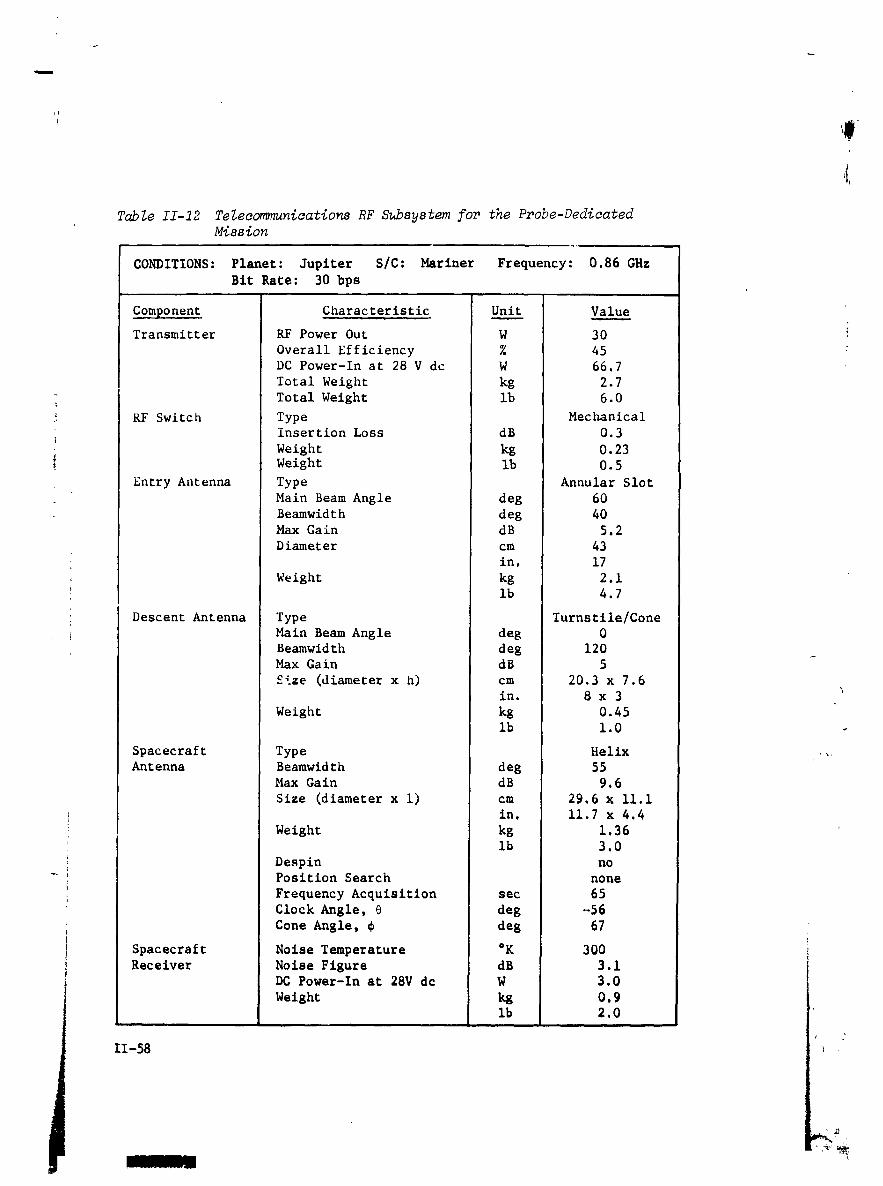
/
Table II-12 Telecommunications RF Subsystem for the Probe-DedicatedMission
CONDITIONS: Planet: Jupiter S/C: Mariner Frequency: 0.86 GHz
Bit Rate: 30 bps
Component Characteristic Unit Value
Transmitter RF Power Out W 30
Overall Efficiency % 45DC Power-In at 28 V dc W 66.7
Total Weight kg 2.7
Total Weight lh 6.0
RF Switch Type Mechanical
insertion Loss dB 0.3Weight kg 0.23Weight Ib 0.5
Entry Antenna Type Annular Slot
Main Beam Angle deg 60
Beamwidth deg 40Max Gain dB 5.2
Diameter cm 43
in, 17
Weight kg 2.1ib 4.7
Descent Antenna Type Turnstile/Cone
Main Beam Angle deg 0
Beamwidth deg 120Max Gain dB 5
Size (diameter x h) cm 20.3 x 7.6in. 8 x 3
Weight kg 0.45ib 1.0
Spacecraft Type Helix ' %,
Antenna Beamwidth deg 55Max Gain dB 9.6
Size (diameter x i) cm 29.6 x ii.iin. ii.7 x 4,4
Weight kg 1.36ib 3.0
Despin no_ Position Search none
Frequency Acquisition sec 65
Clock Angle, O deg -56
Cone Angle, _ deg 67
Spacecraft Noise Temperature °K 300 IReceiver Noise Figure dB 3.1
DC Power-In at 28V dc W 3.0
Weight kg 0.9lb 2.0
II-58
1972026176-071

An analysis was performed to determine the effects of increased
system noise temperature resulting from the flyby trajectory of
the spacecraft intersecting the Jovian magnetosphere. The increase iin antenna noise temperature during pre-entry maneuvers was only59°K, and therefore was negligible.
5. Data Handling Subsystem
_ The configuration and functions of the data handling subsystem_ are essentially unchanged from the nominal Jupiter probe. Refer
_ to Volume II Chapter V, Sections A.5., B.5. and Volume III, Appen-
!, dix H. The physical and electrical characteristics are:
Size: 2580 cm3 (158 in.3); Weight: 2.6 kg (5.7 ib);Power: 18.9 W.
6. Power and Pyrotechnics Subsyste_
The post-separation power subsystem is reduced to a short active
llfe battery bus distribution for this mission. The entry/descent
configuration and functions are essentially unchanged from thenominal Jupiter probe. Refer to Volume II, Chapter V, Sections
A.6., G.6., and Volume III, Appendix G. The physi_cal character-istics are:
i
_ Size 2620 cm 3 (160 in.3); Weight: 6.i kg (13.4 ib). i '
_ 7. Attitude Control Subsystem
The attitude control subsystem is reduced to an ope_-loop splnup(0.5 rad/sec) for this mission. A discussion of the analysis is
contained in Volume II, Chapter V, Section C.7. and Volume III,Appendix F.
i
8 Structural and Mechanical
_ The probe-dedlcated alternative Jupiter probe is a substantiallysimpler probe than the nominal Jupiter probe. For this mission,
the spacecraft provides the deflection delta velocity maneuver.
It leaves the probe in the proper attitude and with the proper
trajectory for planetary entry at the time of separation. Thus,
the probe does not need a deflection delta velocity motor nor
does it need to be spun up to a spin rate of 10.5 red/set (I00 rpm) _to stabilize the probe for firing of the deflection motor and for
precession. Instead, the probe needs only to be spun up to 0.52
i red/set (5 rpm) to stabilize its attitude at separation and ellmi-
hate drift before planetary entry. The probe has no service module.
II-59
I I I IIIIII .........................
|
1972026176-072

The configuration of the probe is shown in Figure 11-26. The _
ejected probe is 1.005 m (39.6 in.) in diameter, 0.604 m (23.8 in.)
long, and weights 126.99 kg (279.96 ibm). Since there is no ser-vice module_ the ejected probe and entry probe are basically the i
same. The descent probe is 0.439 m (17.3 in.) in diameter, 0.492
m (19.4 in.) long, and weighs 42.36 kg (93.41 ibm).
A single stage of parachute descent is satisfactory for this probe,
which is re0"_ired to descend only to 13 bars to satisfy mission
requirements. The selected descent ballistic coefficient of 14.1
! kg/m 2 (0.09 slug/ft 2) for a descent probe weighing 42.36 kg (93.41
ibm) results in a parachute size of 2.59 m (8.5 ft) diameter.
This probe enters the planet at a latitude of 30° as compared with
essentlally equatorial latitude for the nominal probe. This changein entry latitude, plus the relocation of probe components from
the service module (which is deleted) to the entry probe results
in a fairly large heat shield and aeroshell. The heat shield mass
fraction for this configuration is 0.350, resulting in a heat shield
weight of 38.7 kg (85.4 ibm).
The probe basic structure is identical with the nominal Jupiter
probe, The probe is designed by the structural loadings encoun-tered during eDtry at an entry angle of 20°, at a latitude of 30 °,
with an entry ba11istic coefficient of 102 kg/m 2 (0.65 slug/ft2).
These loadlngs are 1650 g peak and a maximum dynamic pressure ofi.i x 106 N/m2 (23,000 ibf/ft2).
9. Propulsion Subsystem
This probe has no deflection delta velocity motor, but does have
a mlnimal attitude stabilizatlon system, weighing 1,5 kg (3.31 lbm).
The proper entry trajectory and pointing attitude is provided bythe spacecraft before probe separation for this configuration.
Thus, the ACS system need only provide a probe splnup to 5 rpm tostabilize the pointing orientation during the pre-entry coast
phase of flight.
11-60
1 1,t
..... ...................................n II 'n |
1972026176-073

+_ REPRIODUCIBILITYOF THE ORIGINAL P,z',r+',_rIS POOR _]
++
i
m
E_OUT FRAME I ) "
1972026176-0_

*,'J
_" REPRODUCIBILITY OF THE ORIGINAL PAGE IS POOR. ]

, .+ ,,,
+ +- :+_ REPRODUCIBILITY OF THE ORIGINAL PAGE IS POOR.
• /
/ /
I I tm
F.OLDOUTFRAME-_ _ "r'' I FI

-- _ REPRODUCIBILITY OF THE ORIGINAL PAGE IS POOR .]%
_I_ _1_v_ _-_U _ •
_;gu_ XX-2e AZ_e_n,ative #u_i_er P_.obe Deeiaa_ed l_ission con_i_ux.ae_on&
--. _ I II-_Z _d II-88
_ I _o_ou_F_ _,I I ................................................1
1972026176-077

I#
i0. Thermal Control Subsystem
Thermal control for the probe-dedicated mission probe is required
to maintain the probe equipment within acceptable temperature llm-its. The thermal design concept is basically the same as the nom-
inal Jupiter probe mission. Multilayer insulation, thermal coat-
ings, and radioisotope heaters are used during spacecraft cruise
and probe coast, and probe thermal inertia coupled with low den-
sity foam insulation is used for entry and descent. For the probe-
dedicated alternative mission, the minimum temperature predictedduring descent was marginal (3°K margin) and two improved probe
thermal designs were therefore investigated. On the basis of those
! investigations, the addition of nitrogen gas environmental control
was included for descent thermal control. For this design, theprobe would be purged and sealed with one bar dry nitrogen gas at
launch and equipped with a nitrogen gas supply bottle capable of
charging the probe volume an additional 2.5 bars during descent.
The delta weight and volume added by the N2 gas supply is approxi-mately 0.41 kg (1.1 lb) and 0.35 1liars based on a storage pres-sure 250 bars.
As before, the pivotal temperature for thermal design was the probe• temperature at the end of the mission coast phase, which determines
the probe entry temperature for descent. Although the probe-i dedicated mission considered either a cool/dense or nominal atmos-
i phere encounter and descent, the primary thermal problem remainsone of losing too much thermal energy to the atmosphere environ-
ment during the cool/dense descent. The probe coast and entrytemperatures, therefore, were increased for thls mission by uslnK
a higher ale thermal coating on the probe and absorbing a higherpercentage of the solar energy during coast. Since the coast tlme
! is longer for this mission (34.5 days), the transient temperature
effects following spacecraft separation were of no consequence. _
! Analytical results show that improved thermal design is obtained! by using the N2 gas environmental thermal control concept. Thei probe temperature margins predicted on the basis of thermal anal-
ysts for the probe-dedicated Jupttez mission are tabulated.
-- Spacecraft Entry-Descent Phase
Cruise Phase, Probe Coast Nominal Improved N2Temperature Martin °K Phase_ °K DosiEn, °K Design, °K
Above Equipment Lower
Limit 37 23 3 19
Below Equipment Upper
Limit 13 19 15 12
i Below Transmitter UpperLimit NA NA 29 28
II-6 _
1972026176-078

Typical probe thermal history and temperature limits are shown in
the discussion for the nominal Jupiter probe.
11. Probe to Spa£ecraft Int_sration i
The probe-dedlcated alternative Jupiter probe integration with the
spacecraft is essentially the same as that described for the nom-inal Jupiter probe.
!4}!
i
11-64
1972026176-079

Bi
E. JUPITER SPACECRAFT-RADIATION-C0MPATIBLE ALTERNATIVE PROBE SYSTEMDEFINITION SUMMARY
As was done for the other alternative Jupiter probe discussed inJ
Chapter II Section C.3, the constraints for this probe were theresults of the Jupiter parametrlcs discussed in Chapter II, Sec-
tion C.I. Compared to the other alternative Jupiter Probe, this
probe provides the deflection, the encounter is essentially equa-torlal and the perlapsls radius minimizes the radiation environ-
_ ment for the spacecraft. These constraints are:
_! Mission Type I in 1979
itEntry Angle -15o (structures design to -20 °)
: Entry Latitude 5"
Perlapsis Radius 6 Rj
Deflection Mode Probe
• _ All other constraints are the same as for the other alternative
Jupiter probe.
Mission Definition
The radlatlon-compatible probe mission is described in Figure II-27
and detailed in Table 11-13. Important mission design results\
are summarized in this section.
a. Interp_unetur_ Tr_so_ So_so_on - The interplanetary tra-
i Jectory is pictured in Figure II-27(a) with 100-day interval noted. _ "+The launch date of November 7, 1979 and arrival date of Septemberti 17, 1981 (trip time of 680 days) result in a maximization of the! payload weight as discussed in Volume II, Chapter IV, Section A.
l As indicated in the figure, the spacecraft arrives at Jupiter
shortly before the view to Jupiter is obstructed by the Sun.
I AnaZye_s - analysis is provided in Figureb. Lawloh The launch
--I II-27(b). Available payload is plotted against lauuch period forthree sets of launch vehicle performance data: standard data forthe Titan 5-S_ent vehicle_rlth and without Burner II, plus up-dated data for the Burner II combination. For reference, thepayload weight (probe, spacecraft, spacecraft modifications, andspacecraft launch vehicle adaptor) is about 454 k_ (1000 lb) fora Pioneer mission and 680 k_ (1500 lb) for a Marinar mission.Thus_ the Burner II option is necessary for Mariner-type missionto obtain a 20-day launch period. The nominal launch trajectorysummarized in Table II-13(a) indicates that the daily launch window
and parking orbit coast t_ are satisfactory.
II-65
i q
• ill II I
1972026176-080

i
II-68
"ol
. ,_" "1, _ipJ,'lllml_F-.i,,_,_,,,,_,"......
1972026176-081

Table II-I$ Radiation-Compatible Alternative Mission $ummarH
a. Conic Trajectory Data
[nterplanetary Trajectory Launch Trajectory Arrival Trajectory
Launch Date: II/7/?9 Nominal C3: 93.6 k=2/sec z VHP: 8.474 km/secArrival Date: 9/17/81 Nominal DLA: 30.5" RA: 161.3"
Flight Time: 680 days Launch Window: !.17 hr D_C: 6.8"Central Angle: 155 _ Parking Orbit Coast: 36 min ZAE: 145.2"
C 3 (I0 day): 97.5 kmR/sec 2 ZAP: 141.4 °C 3 (20 day): 105 k_2/sec 2 RP: RAzimuth Range: 101.7" - 115"
INC: _"
d
b. Deflection Maneuver and Probe Conic
Deflecnlon Maneuver Probe Conic Definition
Deflection Mode: Probe Entry Angle: -15"Deflection Radius: 30 x I0_ km Entry Latitude: 5.10
Coast Time: 35.1 days Entry Longitude: 98.8• AV: 257 _/sec Lead TI--: 3.55 min
Appllcatlol: _ngle: 119" Lead Angle: 6.11"
Out-of-Plane Angle: O" Probe-Spacecraft Range (EnL_¢): 357,422 ka
Rotation for Probe Pelease: 85" Probe Aspect Angle (Entry): 78.4"Probe Reorlentatlon Angle: -53 ° Probe Aspect Angle (Descent): 7.3"Spacecraft _V from Karrh: _A P_obe Aspect Angle (EOM): 4.7"
c. Dispersion Analysis Summary
Naviatlon Uncertslntzea gxecuticn Error_ (3_) Dispersions (3_)
Type: Range-Doppler 167-day arc _V Proportionallty: IX Entry Angle: 6.02"SHAA: 1576 ks _V Pointing: 2" Angle of Attack: 5.60"SMIA: 224 km Probe Orientation Pointing: 2" Down Range: 11.46" __: 86" Cross Range: 2.00"
TOF: 122 sac Lead Atlgle: 6.91" _ .Lead Tl_e_ 37.4 minEntry Tlm_: 38.4 min
d. Entry and Descant TraJector7 Sum_mry
Critical Evant_
Altitudes
Entry Parameters Deacon" Parameters Time from Entry above I aim
Entry Velocity, im/sec: 60 Descent Atmosphere: g = O.l, sac: 8.5 ks: 189Entry Altitude, Im: 304.6 Cool/Dense Max g_ _ec: 18 ks: 66.8Entry i. slug/fr2: 0.65 EOM Pressure. bar: 13 H = 0.7. sac: 4_ Im: 33.4
k8/m2: 102.1 Descent Bx Dmscent Time. min:Entry Atmosphere: s_ug/ft': 0.0_ 3.5.6
Cool/Dense ks/m2: 1_.13 EOH, min: 36.1 ks: -57.5Hax Deceleration, g: 1500Max Dynamic Pressure,
lb/f_2: 2.1 x 10;k4/m2: 1.0 x 10⁶
II,._/
]972026]76-082

c. Approach fr_ecto_ - The approach trajectory is pictured in
Figure II-27(d) and summarized in Table ll-13(b). The spacecraft
flyby radius was selected to be 6 R. to limit radiation damage tod
the spacecraft. Since a low inclination probe trajectory was se- !
lected (entry latitude of 5=) an in-plane deflection maneuver was
used. The spacecraft initially leads the probe, but because of
Jupiter's rapid rotation rate the probe quickly overtakes the space-
craft. The probe aspect angle at the start of descent is 7.3 ° ,
passes nearly through zero, and ends at i0 ° at the enl of themission.
d. Deflectio_ Maneuver - A probe deflection maneuver is used in
this mission at a deflection radius of 30 million km or 35.1 days
from Jupiter. The deflection sequence is illustrated in Figure
II-27(c_. For comparison, a deflection maneuver was targeted at
50 million km. This resulted in a coast time of 61.4 days and
a AV of 152 m/sec to establish the same conditions aL entry.
e. iJaw_gation and Dispersions - The navigatiou and dispersion
results are pictured in Table II-13(c). Standard Doppler and
range tracking is all that is assumed since navigation dispersions
are not significant at Jupiter. The entry dispersions are large
relative to the other missions with 3o dispersions in entry angle
of 6.0 =, angle of attack 5.6 = , and entry time 38.4 min. For com-
parison, the deflection at 50 million km resulte_ in dispersions
of 5.8 °, 5.5 °, and 40.8 min, respectively.
f. Entry and Descent Trajectories - Table li-13(d) summarizes
the entry and descent phases of the mlcsion. The cool/dense at-
mosphere model is used for both phases for this mission. The
entry phase starts at 304.6 km above the i atm pressure leve] and '
ends at the staging of the aeroshell 34 sec later. During this
phase, the peak deceleration of 1500 g is attained. The descent
phase starts after staging and lasts until =he end of mission at
13 bars. The total mission time (entry and descent) is 36.1 min.
2. Science
-. The major differences between the two alternative probes involves
spacecraft/probe functional trades and the entry and descent pro-
file and measurement performance is identical. Thus, the descrlp-
tion given for the other alternative Jupiter probe describes the
functions for this alternative Jupiter probe design.
11-68
i ,Ir
1972026176-083

I
3. System Integration
The functional sequence is similar to that for the nominal Jupiter
probe. The main difference involves the ejection of the service
module. The pre-entry antenna, for this configuration, is ejected
along with Lhe service module. At this time, the transmitter is
turned off and engineering data is stored until after entry. A
detailed sequence is _ncluded in Volume II, Chapter V, Section D.3.
i The power profile and data profile are similar to those for thenominal Jupiter probe.except in the areas just mentioned above for
i the service module ejection. The entry uncertainty of approxi-
i mately 38 min causes the p_e-entry activities to occur earlierthan for the Llominal Jupiter probe. Weights for this configuration
are: ejected weight 166 kg; entry weight ii0 kg; descent weight
47 kg.L
4. Telecommunications Subsystem
The point design for a 6 Rj mission performed during the parametric
studies of Chapter II, Section H.2 was used as a basis for the
, _ radiation-compatible mission. The trajectory is identical in%,
i and latitude to point design 8 described in Section H.2.d.%j,YE'i The descent depth has been raised to 13 bars in lieu of the 30 bars
previously used, and the bit rate is increased to 30 bps. Probe
_ dispersions were similar to the dispersions for that point design. _ ,,
i As a result, a two-position sector search technique was also usedfor this configuration to keep the RF power requirements withinI reasonable limits. The characteristics for the telecommunications •
subsystem are presented in Table 11-14.
5. Data Handlin_ Subsystem
: The configuration and functions of the DHS are unchanged from the
i nominal Jupiter probe. Refer to Section C.5 of this chapter.I
' 6. Power and Pyrotechnic Subsystem
The configuration and functions of the power and pyrotechnic sub-
system are unchanged from the nominal Jupiter probe. Refer to
Section C.6 of this chapter.
7. Attitude Control Subsystem
The configuration and functions of the attitude control subsystem
are unchanged from the nominal Jupiter probe. Refer to Section
C.7 of this chapter.
i II-69
1972026176-084

......... r,
°REPRODUCIBILITY OF THE ORIGINAL PAGE IS POOR. "_
fable II-14 Telecommunications RF Subsystem for the Spacecraft-
Radiation-Compatible Jupiter Mission
CONDITIONS: Planet: Jupiter S/C: Mariner Frequency: 0.86 G_iz Bit Rate: 30 bps
!COMPGNENT CI_XCIERISTIC UNIT VALUE
Transmitter RF Power Out W 55
Overall Efficiency % 45DC Power-ln at 28 V dc W 122
Tota] Weight kg 2.72ib ib 6.0
RF Switch Typ _ Mechanica]Insertion Loss dB 0.3
Weight kg 0.45ib 1.0
Entry Antenna Type Annular Slot
Main Beam Angle deg 85Beamwidth deg 40Maximum Gain dB 5.2
Diameter cm 43in. 17
Weight kg 2.1ib 4.7
Descent Antenna Type Turnstile/ConeMain Beam Angle deg 0
Beamwidth deg 120Maximum Gain dB 5.0
Size (diameter x h) cm 20.3 x 7.3in. 8x 3
Weight kg 0.45ib 1.0
Spacecraft Antenna Type Parabolic Dish .Beamwidth deg 20Maximum Gain dB 18,3 _.Size cm 128
in. 50.5
Weight kg 4.54Ib i0.0
Despin NoPosition Search 2
Frequency Acquisition sec 50Clock Angle, * deg -101
Cone Angle, _ deg 59 and 79
Spacecraft Receiver Noise Temperature °K 300Noise Figure dB 3.1DC Power-In at 28 V dc W 3.0
Weight kg 0.9ib 2.0
I
I1-70
_-_ -_;;_-_r___ I _ i
1972026176-085

8. Structures and Mechanical Subsystem
The spacecraft-radiation-compatible Jupiter probe is very similar
in appearance and arrangement to that of the nominal Jupiter probe, i
The entry ballistic coefficient, which sizes the aeroshell/heat
shield assembly, is 102 kg/m 2 (0.65 slug/ft2). This coefficient
: was chosen to provide a deceleration to Mach 0.7 at a pressure
altitude of approximately i00 millibars, to meet the descent-probe
scientific requirements. Only a single parachute is used for des-
cent into the Jovian atmosphere. The descent ballistic coeffi-_ cient, which sizes the descent probe parachute size, is 14.1 kg/m 2_ (0.09 slug/ft2). This ballistic coefficient combined with a probe
i _ descent weight of 47.0 kg (103.6 ibm) results in a parachute size
: _ roughly the same as that for the probe-dedicated mission [roughly
2.74 m (9.0 ft)]. It is deployed by a pyrotechnic mortar after
_ planetary entry is completed, at a pressure altitude of i00 milli-bars.
The configuration of the probe for the spacecraft-radlation-com-
I patible Jupiter mission is shown in Figure II-28. The ejectedconfiguration has a conical nose cone of 60 ° half angle with maxi-
mum diameter of 0.954 m (37.6 in.) and weighs 165.6 kg (365.0 ibm).The descent probe is 0.47 m (18.5 in.) in diameter and 0.463 m
(18.2 in.) long. It weighs 47.0 kg (103.6 ibm).
The scientific instrument complement of the descent probe is iden-
_nal to that of the probe-dedicated mission; however, mission _ \
requirements result in a different support electrical weight, i
The planetary entry capsule basically consists of the descent _ .
probe surrounded by the fore and aft heat shield. The forward
heat shield assembly, in turn, consists of a titanium structural _
aeroshell capped with a graphite heat shield, and containing ad-
ditional hardware needed for entry. The aft heat shield consists
merely of an aft structural shell coated externally with ESA
5500M3 ablator, and a pyrotechnic system for its ejection.
The structure of the probe is governed by the entry angle of 20°
at a !_titude of 5", resulting in an entry deceleration of 1500 g.
The peak entry dynamic pressure is approximately 1.13 x 10⁶ N/m 2
(23,500 psf), and this value converts to a local pressure normal
to the nose cone of approximately 1.56 x 10⁶ N/m 2 (225 psi). The
descent probe and aeroshell base cover structural weight is
governed by the 1500 g deceleration, while the aeroshe11 itself
is designed by normal pressure on the nose cone. The descent probe
and aeroshell base cover are designed to high strength 7075-T6
aluminum, while the aeroshell is designed of 6A£-4V titanium alloy.
II-71
1972026176-086

e
Ii
The nose heat shield for this probe, like the other Jupiter probe,
is designed of ATJ graphite to the criteria developed by M. Tauberand M. Wakefield of NASA/Ames Research Center. This is discussed
in Chapter V, Section A.8 of Volume II. The mass fraction of
the heat shield including a 2 cm (0.79 in.) carbonaceous backface
insulator is shown to be 0.317. This value takes into account a
correction factor of 0.88, for the probe diameter of 0.94 m (37
in.), and a planetary entry latitude correction factor of 1.01.
Thus, for a probe weight of 110.5 kg (243.8 ibm) at entry, the
resulting heat shield weight is 29.6 kg (67.2 ibm). The beating
for the base cover is estimated based on a heating pulse of 2%
of the nose cone heating. For a 20° entry angle, the total heat-
ing pulse is of the order of 1620 _tu/ft 2, and a heating pulse
time is approximately 8 sec. This heating pulse requires 3.2
kg/m 2 (0.65 Ibm/ft 2) of ESA 5500M3 ablator to protect the basecover.
It is interesting to qote that for this mission, the probe at
separation and again at planetary descent is heavier than for
the probe-dedicated mission. However, for planetary entry con-
figuration, the situation is reversed; this probe is heavier,
because of two factors. For this mission, the heat shield mass
fraction is 0.317 compared to 0.350 for the probe-dedicated mis-
sion _t 30° latitude entry. Also, the probe-dedicated mission
has no service module, and carries through entry components that
are jettisoned in the case of the spacecraft-radiation-compatible
mission probe.
9. Propulsion SubsystemI
The propulsion subsystem for the probe is the same as that for the _
nominal Jupiter probe except for the deflection maneuver delta
velocity requirement, which requires a somewhat different size
motor. This mission has a deflection maneuver of 256.5 m/set
(842 fps) as compared with 221 m/set (725 fps) for the nominal
Jupiter probe.
A spherical solid propellant rocket motor provided for he probe
uses an aluminized solid propellant (described as the baseline
prope±lant in Appendix M of Volume Ill) and has a dual nozzle
configuration to avoid the problem of exhaust impingement on the
carrier spacecraft at spacecraft separation. Using a theoretical
specific impulse, I = 287 sec, the necessary weight of propel--sp
lant to provide the delta velocity is 12.4 kg (27.4 ibm) for a
probe weighing 148 kg (327 l_m), not including the weight of the
motor. This propellant welgh_ must be increased to account for
11-72
| I
1972026176-087

)_ REPRODUCIBILITYOF THE ORIGINAL PAGE IS POOR. i
, LIII_•
Df.ll¢l[_l
llO_l't_14 VIEW
............. i
i I I
FOLDOUTFRAME;/ "'t/a I
I
1972026176-088
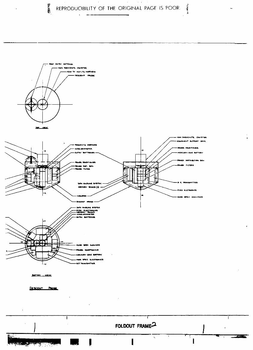
- _ REPRODUCIBILITY OF THE ORIGINAL PAGE IS POOR. _ -4
l.a_w,I II_AKCI_ _.lri,lillITIA
DIIIbClI._,I"I"
mO'_ _EW
i
I I I
! I I
1972026176-089

:- REPRODUCIBILITY OF THE ORIGINAL PAGE IS POOR +_
i
I I I
) , "_'_" FOLDOUT FRAME3 } FOL-_[
' M!DI+, ,+,..- , +, ,,+ .+' _ _J +,
1972026176-090

-4 REPRODUCIBILITYOF THE ORIGINAL PAGE IS POOR. _ --
I ! I
I !
I
1972026176-091

_*, REPRODUCIBILITYOF THE ORIGINAL PAGE IS POOR. 4
1972026176-092
the vectorial loss (i - cos 22.5°) for the dual canted nozzles.
For a propellant mass of 13.4 kg (29.7 ibm), the loaded motorpropellant mass fractlon is 0.80, resulting in total loaded motorweig_ of 17.5 kg (38._ ibm). This weight also includes a weight i
, penalty, above and beyond the mass fraction, of 0.68 kg (1.5 ibm)to account for the extra nozzle. The configuration is the same,
_ except for size, as that for the nominal Jupiter probe.
_; The probe has a service module propulsion system for the spin-
" _ despin-precess maneuver, providing a .:oldgas propellant supply; adequate to spin to 10.45 red/set (I00 rpm), precess through a
" 0.94 tad (53.5°) angle, and despin to 0.52 _ad/sec (5 rpm), as
°i _ well as deflect the service module at Jettisoning. The service
module is Jettisoned just shortly before planetary entry. The
moment of inertia for the radiation-compatlble-mission probe is
close enough to that of the nominal Jupiter probe that it is
assumed to be the same. Thus, the ACS propellant aupply and the
ACS system is the same as that shown in Figure II-19 for the
nominal Jupiter probe.
i0. Thermal Control Subsystem
The thermal control required for the spacecraft radiation-compat- mible probe is the same as the nominal Jupiter mission and the P
thermal analysis shows that this design is adequate to obtain de-
sired probe performance. The probe design requirements are noc
as critical since weight and transmitter power are higher because
of the 6Rj communication distance and the relatively long pre-
entry standby power requirement.
As for all missions, the pivotal design temperature is the probe
temperature established at the beginning of entry. Analysis showsthat with an entry temperature of 300OK, a 15OK margin on required
limits can be created for both the minimum equipment temperature
experienced during a cool/dense atmosphere descent encounter end
the maximum equipment temperature experienced during a nominalatmosphere encounter. Trajectory uncertainties for the spacecraftradiation-compatible probe ate high (± 38 min) and would have
- caused considerable thermal control proble_ if the transmitterhad not been turned off following service module ejection. Sincethe transmitter is deactivated, probe entry temperature uncer-'talnties are only ±3°K.
11-75
I ! I
1972026176-093

i
The thermal coatings used for the spacecraft-radiation-compatible
probe are the same as the probe-dedicated mission. Since the
probe t_mperatures during coast w111 have sufficient time to reach
equilibrium, better thermal design is afforded by establishing a
lower spacecraft cruise probe equilibrium temperature of 286°K.
Results for the spacecraft-radiatlon-compatible Jupiter mission
indicated that the following probe temperature margins will be
expected. Note that the entry-descent upper end lower _quipmenttemperature margins are balanced (15°K).
Spacecraft Probe Coast Entry-Descent
°K Phase_ °K °KTemperature Mar__n Cruise Phase_ Phase_
Above Equipment
Lower Limit 36 26 15
Below Equipment
Upper Limit 14 25 15
Below Transmitter
Upper Limit NA 36 24
Typical probe thermal history and limitstemperature are presented
' in the discussion for the nominal Jupiter probe.
Ii. Probe to Spacecraft Integration
The spacecraft-radiation-compatible mission probe integrationwith the spacecraft is essentially the same as that described for
the nominal Jupiter probe.
II-.76
" I " ' i'
1972026176-094

F. SATURN PROBE SYSTEM DEFINITION SUMMARY
This probe system used the alternative Jupiter probe approach, de-fined in Sections D and E, but adjusted for a Saturn entry and be-
suits of the Saturn parametric .analysis discussed in SectionII.H.3. The general constraints are:
JPL's JS 77 High Inclination for• Mission a Titan Encounter
_ Entry Angle -25 ° (structures designed to -30 °)
f Depth of Descent 7 bars
_ Atmosphere Nominal
Science SAG Exploratory payload (PAET)
r Spacecraft Mariner family
Carrier Mode Flyby
! Periapsis Radius 2.33 RS
Communication Mode Relay
i Deflection Mode Probe
Entry Ballistic Coefficient 0.65 slug/ft 2 (102 kg/m2) • •
Ballistic Coefficient for Heat
Shield Removal 0.].2 slug/ft 2 (19 kg/m 2) I
Descent Ballistic Coefficient 0.7 slug/ft 2 (ii0 kg/m2) !
&
_ The Saturn mission upon which the syr=em design is based is_ described in Figure 11-29 and summarized in Table 11-15. Im-
portant mission design results are disclssed in this section.
II-77
Li---- / I
1972026176-095

a. Interplanetary Trajectory Selection - The interplanetary tra-jectory for this mission is based on the JST mission, a JS 77 mis-
sion including an encounter with Titan. The trajectory is pictured
in Figure II-29(a) and detailed in Table ll-15(a). The trajectoryarrives at Jupiter 1.6 years after launch and passes by at a peri-
apsis radius of 5.8 Rj. The flight time to Saturn is 3.4 year.
and the flyby radius at Saturn is 2.3 RS. Titan is encountered
18 hours before arrival at Saturn.
i
, b. Launch Analysis - The results of the launch analysis are given
in Figure II-29(b) and Table ll-15(a). The available payload
: weight (probe, spacecraft, spacecraft-to-launch vehicle adaptor)
is plotted against launch period for three sets of performance
data. The slight decrease in available payload relative to the
previous Jupiter missions is due to the fact that the inter-
planetary trajectory was selected to satisfy the requirements
of the entire JST mission and not to optimize payload weight.
c. Approach Trajectories - The approach trajectories are illus-trated in Figures II-29(d) and (e) and summarized in Table ll-15(a)
and (b). The spacecraft flyby radius of 2.3 RS was selected to
permit the encounter with Titan but is compatible with an effec-
tive communication link. Thus, the nominal values of the probe
aspect angle begin at 12.42 °, reach a minimum value of 1.86 °,and end at 4.05 ° as the faster moving spacecraft overtakes the
probe. This is most clear in Figure II-29(d) where the view is
from a point nearly normal to the spacecraft orbit plane. Thelocation of Saturn's rings relative to the probe and spacecraft
trajectories is indicated in Figure II-29(e). : '
d. Deflection Maneuver - A probe deflection maneuver was usedfor this mission. The deflection radius of lO.15xlO 6 kmwas se-
lected to give a AV of 170 m/see to obtain an identical deflectionmotor for the Saturn and Uranus missions. The deflection sequence
is illustrated in Figure II-29(c) and detailed in Table ll-15(b).
_" e. Navigation and Dispersions - The navigation and dispersion
summary is provided in Table II-15(c). The spacecraft uncer-
tainties are based on using range/Doppler measurements over an
80-day tracking arc. The SMAAwould be reduced by half by using
QVLBI measurements. The navigation uncertainties have an approx-
imately equal contribution to dispersions as execution errors.The entry dispersions are rather large but are tolerable.
i 11-78
' L
1972026176-096

II-79
III !!!i ':' II
1972026176-097

a. Conic Trajectory Data
Interplanetary Trajectory Launch Trajectory I Arrival Trajectory
Launch Date: 9/4/77 Nominal C3: 99 km2/see 2 VHP: 13.66 km/drvArrival Date: 2/16/81 Nominal DLA: 27.6 ° RA: 195.28 °
Flight Time: 1261 days Launch Window: DEC: 2.54°Central Angle: 207.3 Parking Orbit Coast: ZAE: 173.6 °
C 3 (i0 day): 102 km2/sec 2 ZAP: 169.7 °
C 3 (20 day): 107 km2/sec 2 RP: 2.31 RSAzimuth Ra,ge: INC: 52.44 °
b. Deflection Maneuver and Probe Conic!
i Deflection Maneuver Probe Conic Definition
Deflection Mode: Probe Entry Angle: -25 °D fiection Radius: 10.15 x 10⁶ km Entry Latitude: -50.3 °
Coast Time: 8.02 days Entry Longitude: 102.2 °AV: 170 m/set Lead Time: 55.8 min
Application Angle: 105 ° Lead Angle: -7.63
Out-of-Plane Angle: 2° Probe-Spacecraft Range (Entry): 96,305 km
Rotation for Probe Release: 107 ° Probe Aspect Angle (Entry): 48.2 °Probe Reorientation Angle: -66 ° Probe Aspect Angle (Descent): 12.42 °Spacecraft &V from Earth: NA Probe Aspect Angle (EOM): 4.05 =
c. Dispersion Analysis Summary
Naviation Uncertainties Execution Error_ (3,_) Dispersions (30)
Type: Range-Doppler 80-day arc AV Proportionality: 1% Entry Angle: 5.04°
SMAA: 2178 km _V Pointing: 2= Angle of Attack: 4.00 °SMIA: 760 km Probe Orientation Pointing: 2= Down Range: 12.70 °
_: 89 ° Cross Range: 1.57° ,
TOF: 40 sec Lead Angle: 5.43 °Lead Time: 5.18° _
Entry Time: 7.59 min
d. Entry and Descent Trajectory Summary
Critical Events
Altitudes
Entry Parameters Descent Parameters Time from Entry above i atm
Entry Velocity, km/sec: 37.1 Descent Atmosphere: g - 0.i, sec: 3.0 km: 444
Entry Altitude, km: 491.4 Nominal Max g, sec: 22.5 km: 158Entry B, slug/ft2: 0.65 EOM Pressure, bar: 7.0 M - 0.7, sec: 78.5 Pan: i00.
Descent B, Descent Time, min:Entry Atmosphere: slug/ft2: 0.7
Nominal kg/m2: EOM, mln: 41.7Max Deceleration, g: 350
Max Dynamic Pressure,lb/ft2: 7.0 x lO 3
kg/m2: 3.3 x 10⁵
11-80
!
1972026176-098

f. Entry and Descent Trajectories - Table ll-15(d) summarizes
the entry and descent phases on the mission. Both phases of the
mission were simulated using the nominal atmosphere. The entry
phase starts 491 km above the i atm pressure level (0 km alt =
59,800 km) and ends with the staging of the aeroshell 78.5 sec
later. During this phase, a peak deceleration of 350 g is at-
tained 19.0 sec after entry. The descent phase starts after
staging of the aeroshe!l and continueu through the end of the
mission at 7.0 bars. The total descent time is 40.4 min.
2. Science
The instruments for the Saturn probe are identical to those for
the Jupiter alternative probe. The only difference would be a
modification of the range of the temperature gage and possibly
entry accelerometers for the colder atmosphere and lower g-load.
The results of the descent profile parametrics are:
Design Limit Pressure = 7 bars
Parachute Ballistic Coefficient = 0.70 slug.ft 2 (109.9 kg/m 2)
Parachute Deployment Pressure = 48 millibars
Pressure at First Measurement = 57 millibars.\
Entry Time = 78.5 sec
! pDescent Time = 40 min 25 sec
Instrument Sampling Times:
Temperature and Pressure _ 4.0 sec
Neutral Mass Spectrometer = 60 sec
Entry Aecelerometers = 0.2/0.4 sec
Descent Accelerometers = 8.0 sec
Total bit rate - 26.3 bps
All performance criteria was satisfied. Figure II-30 shows the
selected pressure descent profile for Saturn.
7
1972026176-099

0.02
Parachute
0.05 | Deployment . •
iSaturn Nominal Atmosphere
0.2
-_ 0.I ,.
B = 109.9 kg/m 2
_ (0.7 slug/ft 2)_0.5
- j= NH 3
_i.0
2 _
m
5 _ H20
i0 I I
201 _ J0 i0 20 30 40 50 60 70
Time form Entry, min
Figure II-30 Saturn Probe Pressure Descent Profile
s
II-82
1972026176-100

3. System Integration
The sequence of events is similar to that for the nominal Jupiter
probe in Section C.3 of this chapter except that two parachutes
are used: one (primary chute) to remove the descent probe fromthe heat shield and the other to establish the descent rate. The
_: primary chute is ejected after approximately I meter separation
: _ of the two assemblies. The data profile is similar to that for
the nominal Jupiter probe except that the descent data rate is
_ 26 bps instead of 28 bps. The po,<er profile is similar to £hat
! _ for the nominal Jupiter probe ex: _pt that the transmitter is: ! turned "off" when the service _ocule is ejected. The probe weight
_ at ejection is 107.9 kg (237.9 _-)
4. Telecommunications Subsystem
RF power of 6.5 W is required at 0.86 GHz _..h a bit rate of 26
bps using binary FSK with a tracking tone, A solid-state switchmay be used at this power level. The entry antenna is an annular
! slot which is mounted on the service module under the deflection
motor. The descent antenna is a turnstile over a cone design
which is mounted on the aft bulkhead of the descent probe. The
spacecraft antenna is a helix with right hand circular (RHC) polar-ization and a 35 ° heamwidth. The descent antenna is also RHC
polarized, but the entry slot antenna has linear polarization. ,,
Cross polarization losses occur during entry,but the llnk margin
is high enough to overcome the loss. The spacecraft receiver
is conventional solid-state design with a noise figure of 3.1 dB.
5. Data Handlln_ Subsystem
The configuration and functions of the data handling subsystem
are unchanged from the design of the nominal Jupiter probe with
the exception of minor modifications of sequence and format.
(See Vol II, Chapter V, Sections &.5 and B.5, and Vol III, Appen-
dix H.)
6. Po.wer and Pyrotechnic Subsystem
The configuration of the power and pyrotechnic subsystem is un-
changed from the nominal Jupiter probe with the exception of bat-
tery size and weight. (See Vol II, Chapter V, Sections A.6 and
B.6, and Vol III, Appendix G.) The physical characteristics are:
L
II-83
1972026176-101

Ag-Zn Post-Separation Battery 94 in. 3 6.9 ib
Ag-Zn Entry Battery 39.4 in. 3 2.6 ib
Hg-Zn (Pyrotechnic) Battery ex0.5x3 in. 0.9 lb
The remotely activated Ag-Zn batteries are based on power con-
sumption for this mission.i
i 7. Attitude Control Subsystem - Electronics!
_I The electronics configuration and functions for this subsystemare unchanged for the nominal Jupiter probe design. (See Vol II,
Chapter V, Sections A.7 and B.7, and Vol III, Appendix _.)
8. Structural and Mechanical
The Saturn probe is the smallest of the configurations evaluated.
This is due to the less hostile (from a structural standpoint)
entry environment. The planetary entry decelerations are lower,resulting in lower structural weights. The heat shield mass
fraction is also less, and this, combined with the reduced struc-
tural weight, produces a probe design weighing substantially less
than the Jupiter conflgurationes.
The probe is required to provide a deflection maneuver delta
velocity, and to provide attitude stabilization, and attitudereorientation between the trajectory deflection maneuver and
entry. Thus_ the probe configuration propulsion system includes
a delta velocity motor and an attitude control system.
Two configurations of the Saturn probe were evaluated. Con-
figuration 1 uses the blunt entry nose sha__perecommended by theheat shield analysis results Configuration 2 uses the sameo
1.04 tad (60°) half angle nose cone as that used for the Jupiter
entry probes. Each configuration used the respective heat shieldmass fraction recommended by M. Tauber of NASA/ARC. The heatshield diameters are shown to be almost identical for the two
• configurations. This is due to the drag coefficients being veryclose for the two nose shapes. The hypersonic drag coefficient
M. E. Tauber: Heat Proteotio_ for A_mospheric Entry in#o SaturnjUranus, and Neptune. Preprlnt No. AAS 71-145, 17th Annual Meet-
ing, American Astronautical Society, June 28_ 30, 1971.
Iil84
!
1972026176-102

for the blunt nose is CD = 1.57 while the comparable coefficient
for the conical nose cone is CD = 1.51.
The Configuration 1 Saturn probe is shown in Figure II-31. Gen-
erally speaking, this configuration is much like the other Jupiterprobes, except for the changes necessary to accept the blunt
shape cf the aeroshell/heat shield _ssembly. This blunt nose
: _ shape of the aeroshell forces Lhe descent probe nose to be blunt-
i _ ed also, resulting in a slight rearrangement of internal equipment.' The scientific instrument component complement is the same as
_ that for the probe-dedicated Jupiter mission and for the space-craft-radiation-compatlble mission probes.
_ The second Saturn probe configuration investigated used a 1.04tad (600) half angle conical aero_hell/heat shield structure.
Although the heat shield mass fraction is slightly larger than¥ that for the blunt nose shape of Configuration i, the conical
aeroshell offers packaging advantages for the descent probe, andwas thus investigated. The general arrangement of Configuration2 is shown in Figure 11-32. For this configuration, the aero-
shell structural arrangement is similar to that of the Jupiter
probes. The nose of the descent probe is allowed to project
forward into the areoshe11 at approximately a 1.04 rad (60°) half
angle cone, permitting the equipment arrangement to be less cramped
mld similar to that of the Jupiter probes. This packaging arrange-
ment is a little cleaner than Configuration i. _
The Saturn probe is designed for entry at either the planet Saturn _ .
or Uranus. The entry conditions are close enough for the two i
planets that no appreciable structural weight penalty is involved _ "
in designing for the worst case. An entry deceleration of 380 g iis encountered at Uranus as compared with 350 g at Saturn.
Likewise, the planetary entry peak dynamic pressure occurs at
Uranus. The peak dynamic pressure at Uranus of 35.4 x 10⁴ N/m 2(7400 Ibf/ft 2) compares with 33.5 x 10⁴ N/m 2 (7000 Ibf/ft?) for
Saturn for the respective missions. Thus the entry probe, with
the exception of the aeroshell, is designed to 380 g deceleration
loads. The aeroshell is designed by the normal pressure on thenose cone, which is a function of nose cone shape, and the peakdynaenic pressure at planetary entry. The dynamic pressure atUranus, which is slightly higher than at Saturn, is used fordesign. Configurations I and 2 are .4dentical to the spacecraft-
radiation-compatlble Jupiter probe in structural configurationwith the exception of the aeroshe11 of Confignratlon I. This is
a thin integral rib waffle structure to minimize aeroahell thick-ness •
11-85
J
I Hi Ill I [ ! i
1972026176-103

From Figure II-33 it is seen that the heat shi _,Imass fraction
for the blunt body nose shape for a Saturn entry angle of 0.52 rad
(30°) is 0.145. The mass fraction for the 1.04 rad (60°) conical i
nose and a Saturn entry angle of 0.52 rad (30°) is higher, approxi-
mately 0.215. The former (blunt body) results in a heat shield
weight of approximately 8.9 kg (19.7 ibm) for Configuration i.
Configuration 2 conical nose has a heat shield weight of approxi-
mately 14.2 kg (31.4 Ibm). Therefore, the delta heat shield weightbetween the two configurations is 5.3 kg (11.7 ibm).
The base cover heat shield protection selected is that for the
_i planet Saturn, which is the more severe of the two planets. Theablator material selected is ESA 3560, which is a filled silicone
material reinforced with fiberglass honeycomb.
A two-stage parachute deceleration is supplied for The Saturn-descent probe. This arrangement is necessary because of the
high ballistic coefficient provided foe descent into the atmos-
phere of Saturn. The selected ballistic coefficient for descent
is ii0 kg/m 2 (0.7 slug/ft2). The spent aeroshell/heat shield
assembly has a ballistic coefficient of 43.5 kg/m2 (0.25 slug/ft 2)
after separation, and it is readily apparent that the descent
parachute will not pull the descent probe away from the aeroshell.However, once the descent probe is on the descent parachute, it
will descend faster than the aeroshell assembly. The same para-
chute configurations are satisfactory for use on either of the
two Saturn probe designs investigated.
The ba11istlc coefficient for the separation parachute has been
arbitrarily selected as half that of the spent aeroshell, or
B = 21 kg/m 2 (0.12 slug/ft2). This value provides reasonablerelative deceleration of the descent probe to that of the aero-shell. For a value of dynamic pressure of 1700 N/m 2 (36 lbf/ft2),the relative deceleration is approximately 5 g--ample to provide
separation.
The separation parachute is selected using the above ballistic_. coefficient and a descent probe mass of 37.2 kg (2.55 slugs).
This results in a parachute size of 2.] m (6.8 ft) in dlameter.The descent oarachute has a ballistic coefficient of II0 kg/m 2
(0.7 slug/ft2). A descent probe weight of 37.2 kg (2.55 slugs)
results in a parachute diameter of 0.67 m (2.2 ft).
II-86
i I i
1972026176-104

I I I ',
FOLDOUTFRAME I /......... II 1 , _ I
;_........*:-:_-_-_-....:.........._,,...:_..._,_ I _ IIf!
1972026176-105
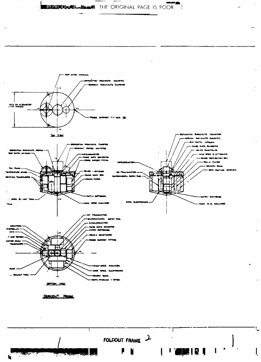
[m14.."nJl_.u_n,, .
[q_Dlv,Lql|,,,_llnmO] THE' ORIGINAL PAGE IS POOR _
I I Fr
/ ,o_T,_E )" )P Ii I mr. DjI!itll n ' ' I,
1972026176-106

1__O];_mLgll_.'llllksOl|lnllsOllt[e_A L PAGE IS POOR. ,_
U
m
)
I I
) ,oLooo+F.,_,_ ) ,c:+++,+ ' !lUi , l_ .......P !
1972026176-107

- F.,
REPRODUCIBILITYOFtHE__q__ Is POOR.;
I I
) ,oL°ooTF.A.E¢ iI I '
1972026176-108

i .............. ,........ ,.I_II;iI(elDUCIBILITY OF THE ORIGINAL PAGE IS POOR. ,7
li_IOi ll_V_JL _M_ "2.
Figure II-31 Saturn Probe Configurationm i
I III-8? and II-88
1972026176-] 09

t+
++_iItlllIlt4,111lltlll'+lllkI,OlIll "IIIO]t4LIII'- "'_Im t+'-"III _I It°_°] t +_+:,., -++
+- I ' t _ I
................ i a

-- *_._ REPRODUCIBILITY OF THE ORIGINAL PAGE IS POOR _
I - 1 I
i m t _ ,,. I
1972026176-111
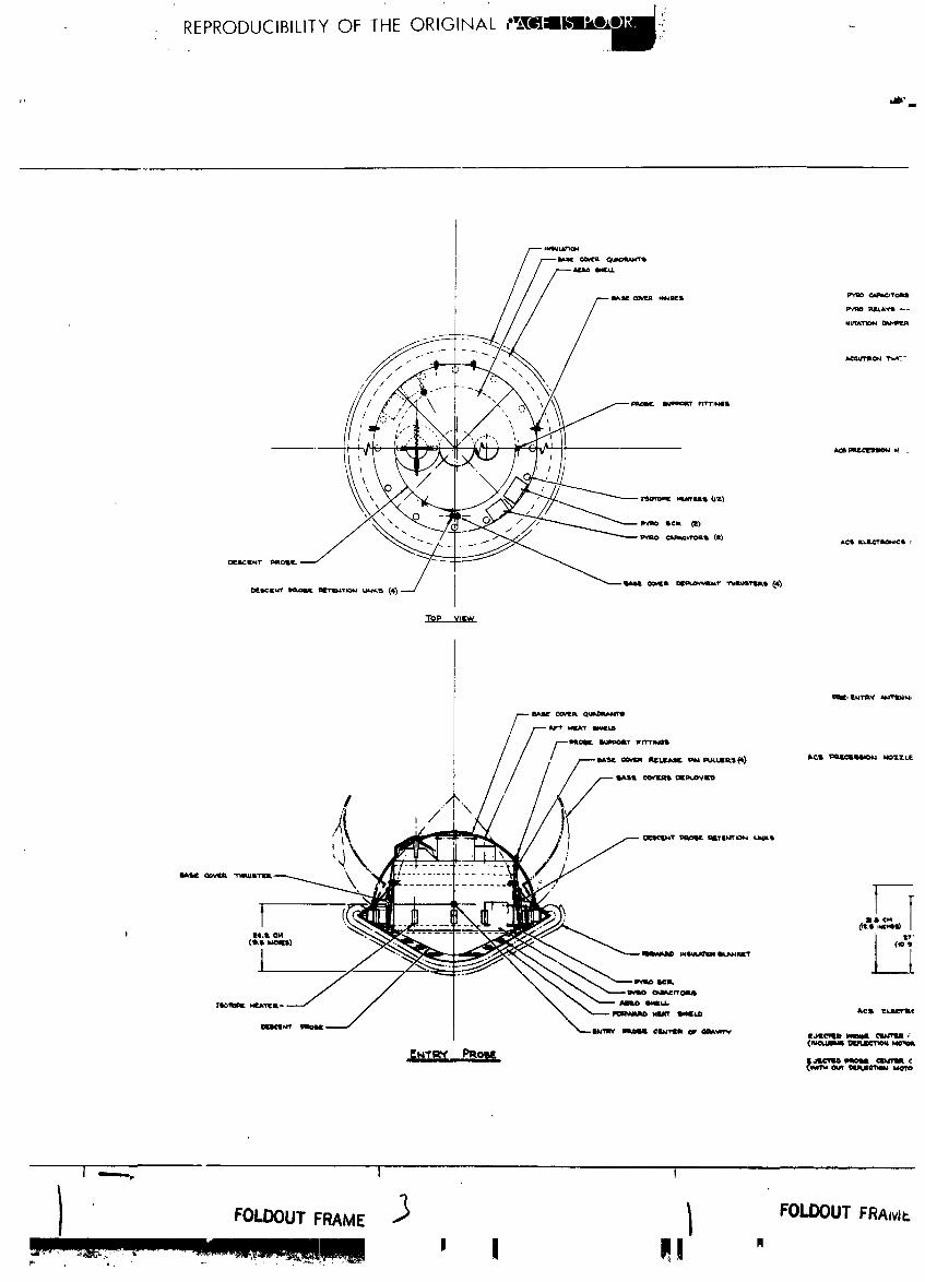
NL*I"ATN_N
TOP WL'W
1972026176-112

__, REPRODUCIBILITY OF THE ORIGINAL PAGE IS POOR.
t l-I_r7 ¢M
NIIAq" ll*_t.D
_'_g_z'_ II-_ A,
,m...--
1972026176-113

REPRODUCIBILITY OF THE ORIGINAL PAGE 'IS POOR ....

O.30 Legend : [
Saturn
85 - 15 arm / m_mE = I00 kg
-- Blunt Body
Cone/ ,
-: o.20 _'
: / /U
_ g_ -_ ........ ,
/ ,=
: 0.10 / _ "i
_ / / i.' ii
2
- f
/
0 -30 -60 -90
YIE' deg
Figu_ .ri-38 Heat ShieZd Mass 1_aot,¢_n _ Entry .4_ forPZ_t 5a_
| II-91
1972026176-115

The two probes are compared in Table II-16. As seen in the table,Configuration i is the lightest.
Ta_e II-16 Configurations I and 2 Comparison i
CONFIGURATION i CONFIGURATION 2
SEPARATION ENTRY DESCENT SEPARATION ENTRY DESCENT
: Weight:
! kg 109 70.6 36.7 116 77.9 37.2,!
ibm 241 156 81.1 257 172 82
Diameter:
cm 78.6 78.6 44.5 78.6 78.6 43.5
in. 31.0 31.0 17.5 31.0 31.0 17.1
Length:
cm 80.3 48.2 42.9 82.5 50.8 44.5
in. 31.6 19.0 16.9 32.5 20 17.5
9. _Pr°puls_-°nSubs_ stern
The _ropulsion subsystem for the Saturn probe is identical to
_hat for the spacecraft-radiatlon-compatlble mission Jupiterprobe except for reduced requirements. This probe is smaller m_d
lighter than the Jupiter probe, and the re£uired deflection maneuver
is smaller, only 170 m/see (557 fps).
The deflection motor for the Saturn probe is the smallest of
those investigated for the various planetary probes. This
motoc is 20.3 cm (8.0 in.) in diameter and weighs 8.9 kg (19.6Ibm). It is a spherical solid propellant motor using (llke the
other motors designed) a du_l nozzle to avoid partlculate impinge-
ment on the carrier spacecraft during motor operation. The deltavelocity of 170 m/sec is applicable to either the plane= Saturn
or Uranus, since these _lanets can use a common deflection del_aveloclty. The probe weight is also co,non for either planet,
thus permlttln_ the moto_ design to be compatible for entry ineither planet.
The attitude contcol system for Saturn and Uranus is smaller
than the other _robes investigaued, because of the reduced probemoment of inertla of approxlmately 6.6 kg/m 2 (5.0 slus/ft 2) . Thusfor a given splnup rate, less total Impulse is required. However,the spin-desp_.n-preces8 nozzles have a grislier moment arm caused
II-92
1972026176-116

by the probe smaller size. This parameter partially offsets the
gain of reduced moment of inertia. The net result is a small
reduction in gas weight and gas container weight for the ACS
system. The total propellant gas requirement for the probe ACSmaneuvers is 1.05 kg (2.33 lbm) and the gas container weight is
1.37 kg (3.02 lbm) for a total system weight of 5.7 kg (12.6 lbm).i
10. Therma] Control Subsystem
A probe thermal analysis was performed for the *_minal Saturn
probe mission defined. These results show that passive thermal"_ design selected is adequate to maintain the probe temperatures
!_ within limits _or cruise and coast, but semi-active thermal con-
__" trol will be required for the more severe atmospheric descent en-!{ counter. Trajectory ua_rtainties for this mission were 8 min-]C utes which is small from s thermal control standpoint. In ad-
"_ dition, the RF transmitter power required for Saturn is small
* (6.5 watts RF) and consequently no transmitter thermal problems
would be expected. For the descent to 7 bars, the N2 gas envi-
ronment control purge system to 2.5 bars pressure was selected
for optimum design.
The probe temperature margins predicted for the Saturn probe_ mission are'
/_ Spacecraft Probe Entry &_ o K_ Temperature Margin Cruise e OK Coasts °K Descent_
_. Above EquipmentLower Limit 42 18 9
_ Below EquipmentUpper Limit 8 25 27
Below Transmitter
Upper Limit NA 3_ 47
ii. Spacecraft Integration
The Saturn probe has been atudied for _ntegration with the JPLMariner Jupiter Satarn Spacecraft, Configuration 2 (JPL Drm_-ing No. 10054478). This spacecraft configuration is shown inFigure II-34.
The integration of the Satcrn probe and the Mariner spacecraftmust have minimal impact on the mission and operation of the
spacecraft. The probe is positioned on the spacecraft to pro-vide for proper ejection, miniupmeffact on the spacecraft sub-
systems, and the least amount of modification of the originalspacecraft concept.
11-93
1_.__, I ! !
1972026176-117

The probe is mounted on the aft end of the _pacocraft wi_ _ it_
centerline angled 31° to the spacecraft centerline, away from
the trajectory ccrrection motor. The probe is supported by tubu- ifar trusseo from the center .avlty of the equipment bay module
with the deflectiop motor nesting into he cav_.ty.
The probe integration with this gpacecraft is sho_m ".iFigure
11-35. The probe shown in the figure is actually the alternative
Saturn probe using a 1.04 tad (60°) half angle nose cune, ratherthan the blunt nose primary conflguration. The installationT
, would be essentially the same for either probe Lonfiguration,
i since there are only minor differences in the probes.
The probe is mounted so that it partially intrudes into _,e volumeof the polygon basic body of the spacecraft. Th_s is done to min-
Imlze the center of gravity shift of the spacecraft-plus-probe
configuration as compared with that of the spacecraft-only cow-
figuration. It is mounted on the end of the spacecraft opposlce
the spacecraft _ :_unicat:_n antenna, so that the probe is pointed
away from the Sun during most of the cruise portion of flight.This permits better the_,ml covtrol _f probe durlng the cruiseportion of flight.
Changes necessary for the Mariner spac,:craft to locate the p.obeas shown in Figure 11-23 are discussed in t_ap_el vl, Section B.IIof Volume II.
i!i i
11-94
tF
1972026176-118

Iit +
- ;;, REPRODUCIBILITY OF THE ORIGINAL PAGE IS POOR. __=::*: 4
' 1 , + 6
+Y
W¢loli4IMill. llllllii Ih
I
1072026176-110

i_ _"- _,,, REPRODUCIBILITY OF THE ORIGINAL PAGE IS POOR. _,_
L
ty
-a:_:_-_U-Z_a( 3-. I! . !....... i ..... I1.. I I
]972026]76-]20

_:'- REPRODUCIBILITY OF THE ORIGINAL PAGE IS POOR. ,_
-IIV llllL_ 4NGI,I[
ULflM ¥10UI LyIIMI* _x
_ TIIY/IIQLAIIiiIlrY
iI_IIM[_ I ULTI_ VIOl,IT SqCIlOSt,,_
N t_
'1I
T
I , , _--- X 41_Y[IPJ[IIIIII_IIT
, ,- - 'l'/ "_i
, , ' , OPTICIU,IO[¢iOfR / / IT
,\_L..-*'C"_'.I .-_ l/_Vi ,_ )' I t\\
i, _" i t i ---r I 1 ' _ - _ . [I f 'l {,.,,,_..... _..---- . ., i(,..l..i;iitt,,...,.__._.
",,.i,'..... .., / ___P ..4-;_J _ . .,,, " . / "W,_/"_" "..:
., -*t, .I, .ii---_!,\: t ./ \_I_;#
\\ ! , _. --I .--f'--......--__/ _i_i*_li._\ _'
O*IIU_
!
11 I ' I I: lil I ' ' _ '
' " ".,,," " " ,.- ,l
< ___..X c:: ..../ -Y ,, i. _ "_+
" I : ,- i _'¢_.,ZX
} EOLDOUTFRAME _ /
1972026176-121

,_ , ,, --r
_, REPRODUCIBILITY OF THE ORIGINAL PAGE IS POOR. _

, ,, ',,
_!i REPRODUCIBILITY OF THE ORIGINAL PAGE IS POOR.
_-- MAI_I_V.I- _ slcr_ _¢4U.WT
I i I
FOLDOUT FRAME / ]m_.h
1972026176-123

- '_II REPRODUCIBILITY OF THE ORIGINAL PAGE IS POOR. _
wv_wol.m
Figza,_II-_5 _aoeo_ _be ln_eH_ion Oonfi_tion•"-"-; "lq
II-8?_d IZ-88
FOLDOUT FRAME 7.._
....................... _. Iml
] 972026] 76-]24

G. SATURN PROBE APPLICABILITY FOR URANUS SUMMARY
The object of this section is to.use the Saturn probe as definedin Section II.F for atmospheric entry into Uranus and based on
the parametric analysis of Section II.E.I, to identify changesonly where the Saturn probe fails to meet the requirements. In
such areas where the Saturn probe more than meets the require-
ments at Uranus, optimization is not considered. The general
constraints resulted from the Uranus parametric analysis and arethe following for the Uranus application:
i " Mission JU-79
Entry Angle -60 ° (structures designed to -65 °)4,
:. Atmosphere Nominal
Science SAG Exploratory Payload (PAET)
Spacecraft Mariner Family
Carrier Mode Flyby
i Periapsis Radius 2.42
Communication Mode Relay
Deflection Mode Probe
Entry Ballistic Coefficient 0.65 slug/ft 2 (102 kg/m 2)
Ballistic Coefficient for "_"
Heat Shield Removal 0.12 slug/ft 2 (19 kg/m2)
Descent Ballistic Coefficient 0.7 slug/ft 2 (ii0 kg/m2)
i. Mission Definition
The Uranus mission upon which the systems design is based is Il-
lustrated in Figure II-36 and summarized in Table 11-17. Importantcharacteristics of the mission design are described in this section.
u. In#er_Zur_ T_aj'eof, o_ - The interplanetary trajectory forthis mission is based on the _JN 79 trajectory. Thd flight time
to Jupiter is 1.6 years with a flyby radius at Jupiter of 9.9 Rj.
The total flight time to Uranus is 6.5 years. The flyby radius
at Uranus was selected to be 2.42 _ to be consistent with the _N
79 mission. Thus, if the spacecraft continues pest Uranus. it willencounter Neptune after a total flight time of 10.3 years.
II-99
4 •
m
1972026176-125

1972026176-126

i B
Table II-l; Uranus Mission S_e_mary
a. Conic Trajectory Data
Interplanetary Trajectory Launch Trajectory Arrival TraJectocy
Launch Data: 11/6/79 Nominal C3: 102 km2/sec 2 VHP: 13.62 lon/secArrival Date: 5/19/86 Nominal LLA: 27.0" RA: 255.1"
Flight Time: 2386 days Launch Window: 4 hr DEC: -29.9"Central Angle: 212.2 Parking Orbit Coast: 40 man ZAE: 174.14"
C 3 (i0 day): 107 km2/sec 2 ZAP: 175.32"C 3 (20 day): 113 km2/sec 2 RP: 2.42"
Azl_uth Range: EL - i0" - ii0 ° INC: 98.02 e
b. Deflection Maneuver and Probe Conic
i _ Deflection Maneuver Probe Conic Deflnltlon
_: Deflection Mode: Probe Entry Angle: -60"
_. Deflection Radius: 9.75 x 10⁶ km Entry Latitude: 53.98"Coast Time: 8.06 days Entry Longitude: 284.17"AV: 170 m/sec Lead Time: 168.3 mln
Application Angle: 33" Lead Angle: -12.07"Out-of-Plane An$1e: 9.1" Probe-Spacecraft Range (Entry): 146,843 km
Rotation for Probe Release: 27.3" Probe Aspect Angle (Entry): 18.03"
_:_ Probe Reorlentatlon Angle: -24.3" Probe Aspect Angle (Descent): 13.91"_ Spacecraft &V from Earth: NA Probe Aspect Angle (EOM): 7.61"
c. Dispersion Analysis Summary
Naviatton Uncertainties Execution Errors (30) Dispersions (3o)
Type: Optical/30. day Tracking arc &V Proportionality: IX Entry Angle: 6°08"SHAA: 1277 km _V Pointing: 2° Angle of Attack: 3.37"SMIA: 424 km Probe Orientation Pointing: 2" Down Rinse: 8.46"B: Cross P_nBe: 8.04"TOF: 440 sac Lead Angle: 6.60"
Lead Time: 1.69 mln
Entry Time: 22.89 _Ln i
d. Entry and Descent Trajectory Summary
Critical Events
Altltudee
Entry P_rametera Descent Psrametera Tlme from Entry above 1 atm
Entry Velocity, kn/sec: 25 Descent Atnosphere: g - 0.1, sac: &.O kin: 444
Entry Altitude, kin: 531 Noutnal Max g, eec: 17.0 knz 138Entry g, elus/ft2: 0.65 EOM Pressure, bar: 7.0 M = 0.7, sec: 54.5 k_: 78.6
ka/m2: Descent B_ Descent Time, mln:Entry Atuosphere: slug/ft': 0.7 43.1
Nominal ks/m2: 109.9 F.OH, mln: 44.0Deceleration, $: 357
Max Dynamic Preeeure,lb/fC2: 7.4 x 10'
ks/m2: 3.5 x 10 s|
11-101
1972026176-127

b. Launch Analysis - Available payload weight is plotted against
launch period for three sets of launch performance data in Figure
II-36(b). It should be noted that the Burner II stage is requiredif the Titan III/5-Segment vehicle is to be used for the launch ivehicle.
c. Approach Trajactories - A front and top view of the Uranus
encounter is provided iu Figures II-36(d) and (e). The spacecraft
trajectory was selected to be consistent with the JUN 79 mission,as explained above. The probe entry angle of -60 ° was selected
to obtain an entry site well on the Sun-lit side of the planet
, The probe was deflected so that at about the middle of descent,! the spacecraft was nearly overhead the probe. This results in a
link geometry quite different from the other missions.
d. De_ection Maneuver - A probe deflection maneuver was used to
establish the above defined llnk geometry and acquire the entryside. A deflectlon radius of 9.75 x 10⁶ km was used in order to
obtain the same AV requirements (170 m/sac) as the Saturn mission.
The implementation sequence is pictured in Figure II-36(c). The
rotation angles are all quite small.
e. Navigation and Dispersions - This design mission is requiredto assume optical tracking because standard Earth-based tracking
results in extreme dispersions. This is caused by the fact thatUranus' ephemeris uncertainties are about t_n times more severe
than those at Saturn. The navigation results provided in TableII-17(c) are consistent with including optical tracking along with
standard Earth-based tracking. Even with the optical tracking,the navigation uncertainties dominate the execution errors in de-
termining dispersions. The dispersions are now quite reasonablebut the subsystems can still be designed to accommodate them.
f. E_t_ and Deso_t T_eotories - Table ll-17(d) summarizes
the entry and descent phases of the mission. Both phases weresimulated using the nominal atmospheric model. The entry phasestarts at 531 km above the 1 arm pressure level (0 k4nalt =26,468 km) and ends with the staging of the aeroehell 54.5 saclater. During this phase, a peak deceleration of 357 g is at-tained 19.0 sac after entry. The descant phase starts after eras-ing of the aeroehell and continues through the end of mission at7.0 bars. The total descent time is 43.1 min.
11-102
] '-
L2 ._ ...... I I I I
1972026176-128

3. Science
The instruments for the Uranus probe are Identical to those forthe 2upiter alternatlve probes. The only difference would be a Jmodilication of the range of the temperature gage, and possiblyentry accelerometers for the colder environment and lower g-lead,respectively.
The results of the descent profile par_unetrics are:
Design Limit Pressure = 7 bars
Parachute Ballistic Coefficient = 0.70 slug/ft 2 (109.9 kg/m2)
Parachute Deployment Pressure = 33 millibars
Pressure at First Measurement = 39 millibars
Entry Time = 43 mln, 4 sec
Instrument Sampling Times:
Temperature and Pressure = 4.0 sec
Neutral Mass Spectrometer = 60 secDescent Accelerometers = 8.0 scc
Entry Accelerometers = 0.2/0.4 _ec
Total Bit Rate = 25.3 bps
All of the requirements have been satisfied, exceeding the criteriain order to keep the £nstruaent smnpl£n 8 times the sane _e Lhoseused for Saturn. Figure 11-37 shows the selected pressure descent
profile for Uranus. i
3. Systm I_teRration i
The functional sequence for Uranus Is very 8£n£lar to thst of, _aturn except for a 23-uin uncertainty at arrive. The data pro-
file is 8inilar to Saturn except for a 25 bp8 data rate durin8descent. The power profile approx/nates that :'dr Saturn exceptfor the effect of the entry uncertainty and for the fact that anedditioual descent battery is required for thsrual control. Com-parisons between Saturn and Uranus pr.bas are shouu in Table 11-18.
I1-103
1972026176-129
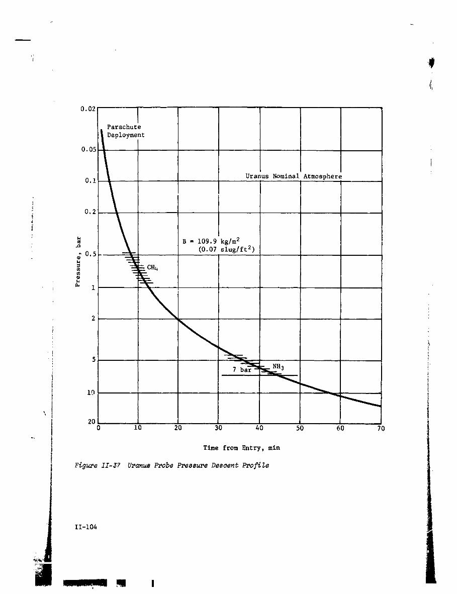
0.02
Parachute
I Deployment0.05
0.i Uranus Nominal Atmosphere
0.2
B = 109.9 kg/m 2
(0.07 slug/ft 2)-0.5-
° 3_ -
!
2
.,... ,5 _
7 _
, !20
0 i0 20 30 40 50 60 70
Time from Entry, min
Figure II-3? Uranus Probe Pressure Descent Profile
q I
1972026176-130

Table II-18 Saturn Probe Comparisons
_ Parameter Saturn Uranus
Probe, AV, m/sec 170 170
_j, x 106 km 10.15 9.75
Entry Ballistic Coefficient, kg/m 2 102 102
_ Descent Ballistic Coefficient, kg/m 2 ii0 ii0
Max Deceleration, g 350 for -30 ° TE 380 for -65 ° 7E
Descent Depth, bars 7 7
_. End of Mission, Entry + 41 m, 43.5 sec 43 m, 58.5 sec
_: Heat Shield Design Mass Fraction 0.215 0.126
Data Storage, bits 12,400 12,400
Descent Data Rate, bps 26.3 25.3RF Power at 0.86 GHz for same Space-draft Antenna, W 6.5 6.4
Descent Battery, W-hr 68 93 + 12 for Thermal :
Pre-Entry Antenna Planar Turnstile/Flared Cone
Thermal Control Partlally Sealed Partially Sealed with
an Added Descent Bat-
tery !
Ejected Weight, kg (Ib) 108 (238) Uranus ejected weight _ "
is approximately 2 kg ._,Entry Weight, kg (Ib) 68 (149) heavier than the Saturn -
Descent Weight, kg (lb) 37 (82) probe.
Heatshleld Diameter, m (in.) (31)
Descent Probe Diameter, m (in.) (17.5)
If-105
_ c
1972026176-131

ii
4. Telecommunications Subsystem
Table II-19 depicts design details of the RF components which com-
prise the telecommunications subsystem for the Uranus mission.
Complete details of the components are given in Volume II, ChapterV, Section A.4. 6.5 watts of RF power is required at 0.86 GHz with
a bit rate of 26 bps using binary FSK w_th a tracking tone. The
subsystem hardware design is identical to the Saturn mission ex-
cept for the preentry antenna which must be changed to a 90° axial
beam. Identical antennas may be employed for both preentry anddescent for this mission.
5. Data Handlin_ Subsystem
The DHS for Saturn and Uranus are essentially identical in con-
figuration and function. The dissimilarities are slight differ-ences in timing, sequence, and format during the entry and descent
phase of the mission. These dissimilarities could be eliminated
by the use of a programmable memory (core, plated wire) or by in-
cluding dual banks of sequence and format control logic. The de-sired mission could then be selected by ground controlled pro-
gramming power switching.
6. Power and Pyrotechnic Subsystem
The power and pyrotechnic subsystem for Saturn and Uranus are es-
sentially identical in configuration. The only significant dis-
similarity consists of the entry/descent (Ag-Zn) battery size andthe Hg-Zn (pyrotechnics) battery size. These dissimilarities could
be eliminated by using the Uranus design batteries, with negligiblecost in weight. _
7. Attitude Control Subsystem
The ACS subsystem for Saturn and Uranus are similar in configura-
tion. The principal differences are (1) sensor design for low
solar intensity at Uranus, and (2) ACS logic. The dissimilarity
of (1) could be eliminated by the use of two Sun sensors, appro-priately mounted for the two missions, and the use of a Uranus
planet sensor that would perform equally well for Satu=n. The
changes in the logic (2) would be implemented by DHS control or
the use of two sets of logic. The additional electronics would
represent a minor increase in weight. The logic and sensor not
in use on the selected mission would be removed from the power
i bus by a latching relay during preseparation checkout and wouldnot require additional power.
II-i06
1972026176-132

Table II-19 Telecon_nunications RF Subsystem for the Oranus Mission
Conditlons_ Planet - Uranus; Spacecraft - Mariner; Frequency _ 0,86 GHz;Bit Rate - 26 bps
Component Characteristic Unit Value i
• Transmitter RF Power Out W 6.5Overall Efficiency % 45DC Power in at 28 V dc W 14.5
Total Weight kg 2.72ib 6.0
4_ RF Switch Type Solid State_ Insertion Loss dB 0.3!
i_ Weight kg O.i_ ib 0.2
_ Entry Antenna Type Turnstile/ConeMain Beam Angle deg 0Beamwidth deg 90Max _ain dB 6
_ Size (dia x h) cm 20.3 x 7.6
_ in. 8 x 3Weight kg 0.45
Ib 1,0
_ Descent Antenna Type Turnstile/Cone
i 'Main Beam Angle deg 0Beamwidth deg 90
• Max Gain dB 6Size (dia x h) cm 20.3 x 7.6
in. 8x 3 i
_i Weight kg0.45
ib 1,0 _ "
Spacecraft i ,_,Antenna Type HelixBeamwidth deg 35Max Gain dB 13,5
Size (I x dis) cm 73.2 x Ii.iin. 28.8 x 4.4
Weight kg 2,72lb 6,0
Despin noPosition Search 1
Frequency Acquisition sec 25Clock Angle, O _eg -I01
Cone Angle, _ deg deg 154.3
i Spacecraft° Receiver Noise Temperature °K 300
Noise Figure dB 3.1DC Power in at'28 V dc W 3,0
Weight ks 0.9lb 2.0
II-107
I I I
1972026176-133

Ii
8. Structures and Mechanics
The entry conditions selected for the planet Uranus results in adeceleration load of 380 g, as compared with 350 g for entry into
the atmosphere of Saturn. This small difference is reflected ina delta weight in the equipment support deck of the probe of ap-
proximately 0.Ii kg (0.25 ibm). Likewise, the delta weight for
the descent probe outer structure is approximately 0.ii kg (0.25
Ibm). The delta weight for the aeroshell base cover is insigni-ficant.
The aeroshell weight is designed by the peak dynamic pressure at
entry. Entr_ at Uranus results in a dynamic pressure of 36 x 104/m 2(7400 ibf/ftz). The delta weight for the aeroshell is approxl-
mately 0.09 kg (0.20 lbm) to accommodate the difference in pres-• sure acting on the nose cone. Thus, it is apparent that the total
structural weight is affected by less than 0.45 kg (1.0 lbm) for
entering one planet versus the other. This value is insignificant;
the probe design for the Joint planet entry is based on the higherloads encountered at Uranus.
Unlike the design of the structure, the severest heat shield re-
quirements are for the planet Saturn. The 65" entry angle at
Uranus requires a heat shield mass fraction of only 0.126 and
would result in a heat shield weight of 7.74 kg (17.1 ibm). For F
the entry angle at Saturn, the heat shield mass fractions is
0.145. The heat shield weight for Saturn is therefore 8.9 kg
(19.7 ibm). The penalty paid for using the Saturn heat shield toenter Uranus is therefore 1.2 kg (2.6 ibm).
9. Propulsion
The delta velocity required for the deflectlonmaneuver is essen-
tially identical for either Saturn or Uranus. The same motor
configuration is thus used for either planet. This motor is dis-
cussed in Volume II Chapter VI, Section B.9.
The precesslonmaneuver for the probe to enter Uranus is only 24°.
The ACS propellant to perform this precesslonmaneuver is 0.141
kg (0.311 Ibm) as compared to 0.388 kg (0.856 ibm) for the pre-cesslov angle for Saturn. Thus, 0.247 kg (0.545 ibm) of ACS cold i
gas propellant could be saved; thus a total system weight (propel-
1ant plus tank) of 0.57 kg (1.25 lbm) could be saved for a Uranus-only probe design.
I
II-108
"1972026"176-'134

i
i0. Thermal Control Subsystem
A probe thermal analysis was performed for the nominal Uranus probe iimission defined. These results show that the thermal design is
critical for this mission because of the low probe entry tempera- _\ ture obtainable (284°K) and the very cold planetary atmosp_ere
_ anticipated. To provide adequate thermal protection for this mis-
slon, both N2 gas environmental control and thermostatically con-
_ trolled electric heaters are recommended (Chapter Vllp SectionA.IO.C in Vol II). The N2 gas provides adequate probe temperature
, _ control until approximately 3 bars pressure (approximately 25 minafter entry) after which time battery heating is required. The
heater power requirement to maintain the battery at 5°k above its
allowable lower operating limit would be approximately 12 W-hr of
_ energy with 50-W peak power required at the end of the design_: mission.
_. The probe temperature margins predicted for the Uranus probe mls-
._ sion are:Spacecraft Probe Entry
Temperature MarBin Cruise, °K Coast_ °K Descent,_ °K
Above EquipmentLower Limit 42 12 5
\
Below Equipment
Upper Limit 8 25 30J
Below Transmitter
Upper Limit -- 38 52
Ii. Probe to Spacecraft Integratlon
Integration of the Uranus probe with the Mariner Jupiter Saturn
Spacecraft is discussed in Volume II, Chapter VI, Section B.II for
Saturn. The only unique requirement for the Uranus probe is that
optical tracking of the planet is required by the spacecraft toreduce the navigation uncertainties as discussed in Section G.I.
II-I09
1972026176-135

H. PARAMETRIC ANALYSES RESULTS
Analyses were conducted in such areas as missions, science and
subsystems as a means of determining constaints for probe defini-
tions. This chapter covers general mission parametric analyses,
followed by those analyses peculiar to Jupiter, Saturn, Uranus,and Neptune.
i. Mission Analysis Parametrics
A summary of the most important mission design considerations is
provided in this subsection where side-by-side comparisons of the
different planets may be made. In earlier chapters of this volume,
individual discussions of each planet were given with references
to the figures included.
a. Launch Opportunity Compaz_9on8 - Available payload (probe,
spacecraft, spacecraft modifications, and spacecraft/launch vehi-
cle adapter) is plotted versus trip time in Figure 11-38 for the
1979 launch opportunity. The result is that for a 20-day launch
period satisfying the range safety constaint, the optimal trip
time is slightly less than 700 days. This corresponds to missions
arriving at Jdpiter just before Jupiter is occulted by the Sun.Th_ payload is based on the standard performance data for the
five-segment Titan with the Burner II stage.
Figure II-39 provides a comparison of the four launch opportunities
between 1978 and 1982. The payloads are based on 20-day launch
periods for the reference missions noted for each opportunity in
Figure IV-16 of Volume II assuming the standard performance data
for the Titan lllE/Burner II vehicle. The progressive improvement _
with each year is clear. Several reference weights are also indi-
cated on the figure to aid interpretation of the results.
b. Rotut_on Rute Mutuhing - In order to approximate the optimal
relay link geometr 7 described in Mission Design Considerations,
Section A, it is necessary that the spacecraft angular rate be as
close to the planet rotation rate as possible. Figure II-40 il-
lustrates the results of a rotation rata matching study for each
of the candidate planets. As indicated, the periapsls radii that
result in effective rate matchlng for mission of about 30-min des-
cent times are approximately 2.7 Rj, 2.5 RS, 3.5 _, and 5.0
for Jupiter, Saturn, Uranus, and Neptune, respectively. Actually
the optimal perlapsis radius is very mlsslon-dependent and must
be computed for the specific entry angle, descent time, and ap-
proach velocity magnitude of the mission under consideration.
II-110
!
1972026176-136

#J
'if
', , , SEV < 15 i i Ii I -[ I I i [ Standard 5-Segment_
1800----+---_--- I 1_ ., _ '.
1600 ----I---' i0 Day7Perlod _ "=_ X [ _ '' L-- I L \
,i/7 "'''°" \// " X N _ _'DLA ` 36°_
1ooo,_ I //
_. I J -
ConetraintI [500 600 700 800 900 1000 ii00 1200
Trip Time, day1
Figur,_. II-_8 Optimization of Trip Time for 1979 Launch to Jupiter ! -
2ooo___. I I .. _ _. IS/C-Probe Deflecter 1500-1b _ "_ Leunch
18001 j M 1350-Ib S/C-Probe Deflect Ir--'r'- -_ 1-- -_ " --_._
i
l_rtln HOPS- SIC l_flect I I I I I_
Martin HOPS - Probe Deflect i _-.._..J / [ I _r_
_ .oo=:'_"-,r--r-T-I t I-T_-_2--t-,-r--
1200 ' '
,%Pioneer-Shared Deflect
. _.--_. _---._ooo----"eT-_..-_'-_r_T'._T.;T--" _
1 ,$ 10 15 20
Launch Period. day
Figure II-39 Comparison of _amoh O_portunities ,,
II-lll
I I
_972026_76-_37

,e
: VHp = 9 km/sec t ' : : T ' _ Vl{P = J 3 km/s_c i i
, , VHp- I1 knl/sec '_ ' - *- _ t
_: 80_ - + ' i /_ VHI = 7 km/sec -_ 80! " ! '1.5 ,L, : ' t- , . __ _ .t_,,-_--+--d---f--_
r [...j11 , ! _ ,= -_-_ + _--,?--- _ 6oi ...._ ..... _--_--+--_--+---_
_ 6o---_-_', r" +iff/_r, k, ', .....' ' _ . --.'---+' i. 12__Rsl2Rti-_--_ ..i'_____ 'l-Jupiter t t;_-! , , _ ' Satorrl / _ _I I J ,
,o[-_'¢r. H-I'', : : _ : ,o .,.er: _i :\\ -
L/i.i . :-. - ..... , • 1o o. _. ._ ......___L__I-3 -2 -I 0 I 2 -3 -2 -I 0 I 2 3
Time from Periapsis, hr Time from Perfaps/s, hr
Neptun_ I '
120 ..... 120r = 13 kmlsec - ' - T .....
i R_. , , VHP i + _-- -Uranus . 1.5 _ ' " _ - - -
VHp = 13 km/sec U I
Ar,_ '."_ : ,oot . ....+. II "'_.-VHp = 9 km/sec--
! , I _"8or t t---f "- --
: - J _li _ , } : i r-6Q ---
uranus . . _
" deglhr
I0 .... _ ___-t
-3 -2 -I 0 1 -3 -2 -I 0 I 2 3
Time from Perlaplis) hr Tim_ [tOm Peli,pSil. hi
Figure T_T_-_O Rata#ion Rate _tohit_ at PZanet8
II-i12
) .
- !_'_*I_': 4_"_,,'_ .........--w.-"..........
1972026176-138

c. Deflection AV Requirements - Deflection AV requirements are
given for a wide range of parameCrics in Figure 11-41. The im-portant trends are summarized here.
Deflection Radi_ - The &V requirements are reduced drasticallyas deflection radius is increased. This is apparent from the
significant downward slopes of all the curves even when plottedon a logar_thmic scale as in Figure II-41.
i Spacecraft Periap_ic - The &V requirements are about linearly
J proportional to the spacecraft periapsis; doubling the periapslsradius doubles the AV requirements for a fixed deflection radius.
Entry A_le - The &V requirements Increase with entry angle as
indicated for Uranus in Figure 11-41. For the Jupiter nominal
mission (2 Rj perlapsis, i0 x 106 km deflection radius), the AV
requirements increased from 205 to 221 to 249 m/sec, respectively,as the entry angle increased from -i0° to -20° to -30 °.
Approach Velocity - The AV requirements increase only slightly
_ with approach velocity VHp. For the Jupiter nominal mission
(2 Rj periapsisp i0 x 106 km deflection radius, -20 ° entry angle),
i the AV increased from 214 to 221 to 225 m/sec as the wasVHp
increased from 5 to 8.47 to ii m/see.
Deflection Mode - A comparison of the dV requirements for the
three deflection modes is provided in Figure II-41. The _V re-
quirements for the probe in probe deflection and the spacecraft iin spacecraft deflection are identical Generally for shareddeflection, the probe AV is slightly higher than this value and !the spacecraft &V is slightly lower.
P_unetu2,,y Comparisons - The AV requirements are approximatelyproportional to the mass of the planet as indicated. Thus, rea-sonable deflection radius ranses appear to be 10-50 million kmfor Jupiter, 10-30 million lm for Saturn_ and 5-15 million kmfor Uranus and Neptune.
[
11-113
im,, l
1972026176-139

,_V-Probe or S/C Deflection biode
q-----.. Probe ,'IV - Shared Deflection
_-o--- S/C &V - Shared Deflection
30C - , 300_-
L- 201 - _ 6Rj
2Rj 2RS
Jupiter Saturn
Vxp = 8.474 km/sec VHp = 14.87 km/secy = -20" y = -20"
i0 50 10 20
Defiectlun Radius, 106 km Deflection Radius, 106 km
100C
70( - -
50C
oo \• 6%(y- -2o') _ _ 6_
4C " 16" 4C
3C-
Uranus 2( -- . NeptuneRp 2.42 _ ¥ . -20 e
VHp - 13.617 knlsec VHp - 15.k6.I I I I i i3 I0 13 $ 10 15
Deflection Radiu_, 106 ks Deflection Rld.4ue, 106 kn
,, Fi_ II-41 Compa_,aon of DofZao_i_ AV Raquiromanta
j v ""
I _-11_ ". i_ -! !
1972026176-140

d. D_spersion Pc_c_etrics - The entry dispersions are produced
by both errors in the spacecraft state at deflection caused bynavigation uncertainties and errors in the delivered deflection
AV caused by implementation errors. Table II-20 compares therelative contributions by these two error s_urcez for missions
at Jupiter, Uranus, and Saturn. The execution errors (3_) in all2°cases are 1% proportionality, pointing, and 2° orien_&tJon.
The navigation uncertainties for Jupiter and Saturn assumed Dop-
! pler/range _racking only; the 0ranus mission assumed opticaltracking. For each mission, dispersions are given for navigationerrors only, and for the combined effect3 of both navigation and
execution errors. It is seen that at Jupiter the dispersions are
totally dominated by execution errors. At Saturn, navigation
and execution errors have about an equal effect. At Uranue naviga-
tion errors begin to dominate; the fact, with Earth-based tracking,
i% of the probes would miss Uranus. Even using optical tracking,the lavigation errors have a significant contribution ro the net
dispersions. Planet independent trends in dispersions ,_uch asi deflection radius effects or entry angle effects are discussed
in the individual planet parametrics of this volume or in the de-
tailed dispersion analyses contained in Chapter IV.F. of VolumeII.
e. Ent_j Pc_ametrics - To provide a quantitative comparison ofthe entry environments of the different planets, Figure II-42 isincluded. Here, the peak deceleration experienced by the probefor a variety of entry angles is given for each of the planets. ',For Jupiter, both the cool/dense and nominal -_dels of the atmo-
sphere are compared. The relative severity _f the Jupiter atmo-sphere should be noted,
t
II-115
__ =, .............................. I_
1972026176-141


Saturn EntryNominal Atmosphere
350
3ooc- _ aoo _/_B = 1.4 to 0.4 _ B = 1o _/B =0.5
•_ _ 250 #f
Cool/Dense
2000- Atmosphere B 14 _ 200 jf
Y_ B = 0.4 _ _ 15C
_ lOOO- ,: I00
i_ Jupiter 50_ Nominal Atmosphere
I., I [ I-i0 -20 -30 -40 -i0 -20 -30
- Inertial Entry Flight Path Inertial Entry Flight PathAngle, deg Angle, deg
40( Uranus Fntry
/Nominal Atmosphere
35( I t
301 300 _Nominal Atmosphere--
_ VIE = 26 km/sec _• _ 25( 250
200 f o 200 /S = 0.5
u 150 /
OJ
° / '_ t
,_ I00 e _o 100a
50
O |
I 0 -20 -40 -60 0 -I( -20 -30 j]Inertial Flight Path Inertial Flight PathAngle, deg Angle, deg
I FigureII-48 MaximumDecelerationComparisonsfor Jupiter, lSaturn,Uranusand Neptune
II-ii7
I
1972026176-143

'if
2. Jupiter Parametric Analyses Summary
The Jupiter studies, as was previously shown in Figure I-i, con-
sisted of defining a nominal Jupiter probe (Section C) using a
set of nominal constraints that were determined from the previous
study results and from other studies conducted by JPL. This nomi-
nal probe definition was used as a reference from which alterna-
tive constraints were varied individually to assess the sensitiv-
ity of the constraint. From this data, two sets of alternativefJupiter probe constraints were determined and two different alter-
_ native Jupiter _robes defined (Sections D and E). The Jupiter •
parametric analyses included in this section are divided into such
disciplines as mission analysis, science, followed by the subsys-
tems analysis.
a. M_88_on AnaZys_s - The detailed mission analysis and design
studies are provided in Vol II, Chapter IV where comparisons of
missions to the different planets may be made conveniently. A
qualitative summary of the important results as they apply to
Jupiter missions is given in this section.
The most critical consideration in selecting the interplanetary
trajectory (or equivalently the launch and arrival dates) for
Jupiter probe missions is payload capability. For a typical launch
opportunity (1979), a flight time of slightly less than 700 days
maximizes the payload capability for a fixed launch energy and
period. This result is based on two constraints: the declination
of the launch asymptote must be less than 36 = and the Sun-Earth-
vehicle angle at arrival must be greater than 15 °. This results
in optimal missions arriving at Jupiter before the Earth passing
behind the Sun relative to Jupiter.
The payload capability improves each year in the period 1979-1982.
This results not only from a progressive increase in the width of
the launch energy contours each year, but also a continual reduc-
tion in the area eliminated by the DLA constraint.l
For the 1979 mission opportunity, the Burner II stage is required
in addition to the Titan 5-Segment launch vehicle to have a 20-
;' day period for a Mariner class spacecraft. The Burner II stage
is not required for a Pioneer class spacecraft.
For the approach selection, the relative geometry between the probe
and spacecreft trajectories optimally would have the spacecraft
directly overhead as the probe descends through the atmosphere.
This would first require that tne probe and spacecraft trajectory
11-118
L! i
1972026176-144

inclinations be chosen in concert. Generally, the probe trajec-_ tory should be a posigrade, low inclination L_ajectory to minimize
- the probe's relative velocity at entry, and thereby reduce entryeffects. Then, the spacecraft should also have a posigrade, lowinclination trajectory.
A second consideration involves the selection of the spacecraft
periapsis radius. While in terminal descent, the probe rotates
with the atmosphere at Jupiter's rotation rate of 36.6°/hr (equa-_ torial). For the spacecraft to match this angular rate, it should
_ have a periapsis radius of about 2.0 to 2.5 Rj for mission dura-
tion times of about half an hour.
In the navigation and guidance consideration, the uncertainty inthe state of the spacecraft at deflection is essentially causedby the navigation uncertainties at the time of the last midcourse
maneuver. A detailed analysis of the navigation results is given
in Vol II, Chapter IV. The navigation uncertainty for the 1979_ mission, using Doppler only, is characterized by a one-sigma semi-
major axis (SMAA) uncertainty in the impact plane of 1600 km
(30 x 106 km deflection radius). Adding ranging measurements andthen QVLBI measurements reduces this to 1500 km and 1400 km, re- •
spectively. Deflecting at radii further from the planet requires
tracking further from the planet which results in less effective
tracking. In going from i0 to 50 million km the uncertainties
are approximately doubled. Finally, the navigation characteristicsvary from year to year as the geocentric declinations of Jupiter
at arrival vary. The SMAAs go from 950 to 1500 to 700 to 450 as
the launches proceed from 1978 through 1981/1982 with correspond-
ing geocentric declinations at arrival of i0°, 0° -15° -23 °respectively.
The deflection maneuver parametrics considers the purpose of thedeflection maneuver as follows:
1) to place the probe on a trajectory intersecting the selected
entry site;
2) to orient the probe for zero relative angle of attack at entry;
3) to establish an effective communication link between the probe
and spacecraft during the critical descent phase of the mission.
The standard means of accomplishing these objectives is probe de-flection wherein the probe is separated from the spacecraft, fires
a AV which accomplishes (I) and (3) above, and then reorients it-
self to the attitude required in (2) by a precession maneuver.
II-119
! II lW'
1972026176-145

The AV requirements are such that the deflection radius (the dis-
tance from the planet when the maneuver is performed) is generallybetween i0 and 50 million km. For a spacecraft periapsis radius
of 2 Rj and an entry angle of -20 °, the AV requirement varies I
from 221 to 73 to 44 m/sec as the deflection radius increases from
i0 to 30 to 50 million km, respectively. The AV increase by a
factor of 3.5 if the spacecraft periapsis is raised to 6 Rj.
Increasing the deflection radius also increases the coast time,which results in a longer length of time during which the probe
is away from the protective environment of the spacecraft, and
during which dispersions may grow. The coast time is approximate-
ly a linear function of deflection radius varying from 9.5 to 34.6to 61.4 days as the deflection radius is increased from i0 to 30to 50 million km.
The uncertainty in the spacecraft state at deflection caused by
errors and the error ia the delivered AV caused by execution er-rors, result in dispersions that must be accounted for in the
design of the probe mission. Dispersions in entry site and entryflight path angle affect science return and interpretation. Dis-
persions in angle of attack at entry affect science as well as
structural, thermal, and aerodynamic design. Dispersions in en-
try time affect mission sequencing. Dispersions in the relative
geometry of the probe and spacecraft determines requirements onthe communication link.
For Jupiter missions dispersions are aominated by execution errors
and the navigation uncertainties ha_e little impact. Approximate-
ly 95% of the total dispersions associated with any of the param-eters discussed above are contributed by execution errors. "
The dispersions are, of course, a function of the level of exe-
cution errors. The proportionality error of 1% (3o) is dominatedby the less well-defined pointing error in the delivered _V, which
is assumed to be about 2° (3o). Using entry angle as a typical
example, 3o dispersions of 0.2= , 0.9 °, I.i =, and 1.3 = result from
assuming AV pointing errors (3o) of 0=, 1.5°, 2.0°, and 3.0 °, re-spect4vely, while holding the navigation uncertainties and propor-
tionality errors (1%) constant (for the nominal mission).
The dispersions are also proportional to the length of the coastarc between deflection and entry, and to the magnitude of the de-
flection AV. Therefore, there is a complicated trade in increas-
ing the deflection radius which lowers the deflection AV and in-creases the coast time.
11-120
1972026176146

Two alternative deflection modes have been identified in addition
to the probe deflection mode discussed above. These are--
I) Shared Deflection (Planar) - The probe is released in the at- i
titude required for zero relative angle of attack. The AV magni-tude is then chosen so that when fired in the axial direction,
the probe impacts the entry site. The spacecraft is then correc-ted to establish the desired co==nunication geometry.
2) Spacecraft Deflection - The initial spacecraft trajectory isr targeted to impact the desired entry site. The probe is released
in the attitude required for zero relative angle of attack. The
spacecraft then rotates to a new dircction and fires a _V whichdeflects it for the desired flyby radius and communication geom-
etry.
The deflection &V requirements for the probe and spacecraft de-
flection modes are essentially identical as they are mirror images
of each other. The two &V required by the shared deflection are
approximately of the same magnitude as the probe or spacecraft
deflection mode AV. Thus, for the nominal mission, the dV re-; quired for the probe (in probe deflection) or spacecraft (in space-
craft deflection) is 221 m/sec, while the probe AV is 246 m/sec1
and the spacecrafL &V is 236 m/see in the shared deflection mode.
According to dispersion comparisons of the three modes, the space-! craft deflection is best and shared deflection is worst. Entry
dispersions (entry angle, entry site, etc) are smallest for the :
spacecraft deflection as no deflection AV execution errors areadded to the probe trajectory. The communication parameter dis-
persions for shared deflection are largest because execution ..
errors have been added to both the probe and spacecraft in that i
mode. Any time a AV maneuver is performed, resulting dispersions
are approximately proportional to the size of the maneuver, i
The critical entry parametric studies deal with the selection of
the entry ballistic coefficient which permits deceleration to lessthan Mach 0.7 above 100 mb for the staging of the aeroshell and
the study of the behavior of the peak decelerations and maximum
dynamic pressures with a variety of entry conditions.
A ballistic coefficient of 102.1 kg/m 2 (0.65 slug/ft 2) results inveloclties below Mach 0.7 at 100 mb in the cool/dense model and
90 mb in the nominal atmosphere for an entry angle of -20 °. To
meet the staging requirements at an entry angle of -30 ° for the
cool/dense atmosphere requires a ballistic coefficient of 78.5 kg/m 2.
II-121
I m
,, I II
1972026176-147

Tile peak g experienced at entry angles of -i0 °, -20 ° , and -30 °
are 675, 1500, and 2250 g, respectively, in t1_ .:ool/dense atmos-
phere, and 450, 920, and 1450 g, respectively, in the nominal
atmosphere (equatorial entry). Thus, the cool/dense model has g i
levels roughly 50% higher than the nominal atmosphere. Entering
at higher latitudes increases the peak g as the relative velocity
is increased. Thus, entering at latitudes of 0° 30 ° and 90 °
latitude results in peak g of 1500, 1650, and 1800 g, respectively,
for an entry angle of -20 ° in the cool/dense atmosphere. The
• peak g level is essentially independent of the ballistic coeffi-
cient. However, increasing the ballistic coefficient delays thetime at which the peak g is achieved.
: The maximum dynamic pressures are functions of b_ilistic coeffi-
cient. Entering with a ballistic coefficient of 157 kg/m 2 at
entry angles of -i0 °, -20 °, and -30 ° results in max q of i0, 22,
and 40 x 103 psf, respectively, in the cool/dense atmosphere and
6.6, 14.7, and 26.6 x 10³ psf, respectively, in the nominal atmos-
phere. The dynamic pressure increases linearly with ballisticcoefficient.
b. Su_enc_ - The major parametrics performed in the science area
were to establish a descent profile that would satisfy the objec-
tives of the mission by making the necessary measurements within
the criteria. The para_.eters involved are: (i) the main para-
chute ballistic coefficient, (2) the drogue or secondary parachute
ballistic coefficient, if one is necessary, (3) the pressure at
parachute staging, if required, (4) the design limit pressure,
and (5) the sampling times for each instrument. The total descent
time is also considered because of the limited time the flyby
spacecraft is available to establish relay communications llnk. .
Also, for Jupiter, the model atmosphere for descent is bounded by
two distinct models: the nominal and cool/dense, and these param-
eters are considered separately in each.
The cool/dense model atmosphere was investigated first. The range
of the ballistic coefficlen_s considered were from 7.B5 kg/m 2
(0.05 slug/ft 2) to 39.25 kg/m 2 (0.25 slug/ft 2) for the main _ara-chute (B1) and from 157.0 kg/m 2 (i.0 slug/ft 2) to 378.8 kg/m z (2.4
slug/ft 2) for the secondary parachute (B2) with staging pressures
from 3 to 15 bars. The size and weight of the main parachute sys-
tem establishes the lower limit for B1 while the descent time and
velocity and resultant measurement performance constrln the largervalues.
L
11-12.9
l
i I
"1g72026"176-'148

!
The results of this parametric analysis are summarized herein.
To descend to 30 bars of pressure, a double _.arachute system is
required. The first parachute must allow the descent probe tofall at a slow enough velocity to enable the measurements to meet
the criteria at cloud tops. The second (smaller) parachute is
necessary to allow the probe co descend faster at higher densities
, so that it reaches 30 bars in a reasonable time, compatible withcon_nunications. The value of the second parachute ballistic coef-
l
_: ficient, within the range studied, had very little effect on _he_ descent profile. However, the pressure at staging must be 8 bars
_ _ or greater, depending upon the exact selected value of BI, inJ order for the instrument measurement performance to meet the cri-b: terla immediately after staging.
The gradient of pressure with respect to distance in the nominal
atmosphere is smaller, thus the clouds exist higher in altitude
and lower in pressure, and the pressure gradient across them isless. This has two distinct effects. One is that since the clouds
are higher, the probe will not have to penetrate as deeply to sat-
i isfy the mission objectives. In fact, descent to i0 bars in thenominal is roughly equivalent in relation to objectives as descent
_ to 30 bars in the cool/dense. This eliminates the necessity fora dual parachute descent, as for all ballistic coefficients stud-
ied, =he times to i0 bars are less than 54 minutes. Secondly,
the pressure gradient being less means that to obtain equivalentmeasurement performance in the nominal as in the cool/dense, the
velocity with respect to pressure must be less. Therefore, the
time to descend to a given pressure level is longer, for a given
ballistic coefficient. This is summarized by Figure II-43.i
The range of main parachute ballistic coefficients studied for the ._
nominal atmosphere was the same as for the cool/dense. Results
show that for optimum performance, the value of B for the nominalshoul 4 De smaller than that for the cool/dense, and it can be
noted that for a given value of B, the instrument sampling elmesmust be shorter to satisfy performance requirements. Furthermore,
since the nominal atmosphere is the worst-case for measurement
performance, a probe designed to meet the criteria in the nominal
will also satisfy it in the cool/dense, and any combination inbetween.
The model atmosphere also has an effect on data rate, For the
same ballistic coefficient and terminal descent pressure t the scl-
ence data rate can be approximately the same regardless of thedescent time_ but if both entry phases are in the same atmosphere,
the descent in the cool/dense model will require a higher bit rate.
II-123
a i i 1
1972026176-149

1 I I I II III I I I II Ill0.01 0.I 1.0
Ballistic Coefficient, slugs/ft 2
Figure II-43 Descent Times to Varioua Pressures in Both J,_piterModel Atmospheres
II-124 1 '
k
]972026]76-]50

The entry flight path angle affects the entry phase directly bychanging the time to reach Mach 0.7 and the descent phase indi-
rectly by changing the altitude at which Mach 0.7 is reached, thusvarying the starting point in the atmosphere for descent. The i
combined effect can cause the total mission time to vary up to
about 2 min. However, variation in entry time has a strong effect
on total bit rate since entry accelerometers are measuring up to200 bps.
• c. System Integration - Guidelines for the program parametric
_ analyses point designs are shown in Table 11-21. The reference
configuration is the nominal Jupiter probe.
Table I7-21 Constraint8 for Program Parametric Point Designs
Configuration
Constraint Ref 1 2 3 4 5 6 7 8 9 i0 ii
Rp (Rj) 2 2 2 2 2 2 2 2 6 2 2 2
REj (x lO t km) i0 i0 i0 i0 I0 i0 I0 i0 30 i0 i0 i0
YE (- deg) 20 i0 30 42.6 20 20 20 20 20 20 20 2_
Latitude (deg) 5 5 5 90 5 5 5 5 5 5 5 5
i E CD CD CD CD CD NOM CD CD CD CD CD CDArm D CD CD CD CD NOM NOH CD CD CD CD CD CD
Deflection Mode P P P P P P p p p S/C S/C S
S/C !MOPS MOPS MOPS MOPS MOPS MOPS PION MOPS MOPS PION MOPS PION
Descent (bar) 30 30 30 30 i0 I0 30 30 30 30 30 30i
Legend: CD-Cool/Dense; NOH-Nomlnal; P-Probe; E-Entry; D-Descent. _
d. Teleco_n_ieation Sul_system - The parametric analyses were in-
tended to determine the effects of variations in trajectory param-
eters on the design of the probe. Major trajectory parameters,
such as periapsis radius and entry angle, affect RF power require-ments significantly.
Considerable effort was expended in determining if an optimum op-
sratlng frequency exists since several losses ere directly propor-tional to frequency and others are inversely proportional to fre-
quency. The analysis is discussed in detail in Volume III, Appen-
dix B. Results of the frequency selection indicate that an optimum
frequency does not exist, but, in general, the lower frequenciesare affected less by the RF llnk variables. For this reason, tha
original operating frequency at S-band (2.3 GHz) was abandoned infavor of a frequency near 1 GHz.
|
II-125
1972026176-151

Signal attenuation in the cool/dense atmosphere for 1 GHz variesfrom 2.2 dB at 30 bars to 0.2 dB at i0 bars, and for 0.86 GHz,
it varies from 1.5 dB at 30 bars to approxlmate_y 0 at i0 bars.
The nominal atmosphere has significantly less loss. A furtherdiscussion of the losses is included in Vol II, Chapter V, Section
A.4 and Vol IIl, Appendix A.
Several types of antennas are required for the various missions
depending on beamwidth and frequency. Antenna designs are dis-
cussed in detail in Vol III, Appendix D. The spacecraft antenna: for narrow beamwidths (<20°) uses a parabolic dish antenna of con-
, ventional design. For missions tbat require high gain, a dish
"! antenna provides a compact design. Circular polarization is re-
quired since the probe is spin stabilized. Missions that requirea spacecraft antenna with a wide beamwidth and low gain use a
helical antenna. Probe pre-entry antennas must have a butterfly
pattern because of a large probe aspect angle before entry. For
the parametric designs at 1 GHz, a spiral design on a cone was
selected. The probe descent antenna uses a turnstile design over, a flared cone to provide circular polarization, a large axial pat-
tern, and a compact design.
: The probe transmitter uses solld-state design with an overall ef-! ficiency of 45Z. The transmitter is switched from the entry an-
! tenna to the descent antenna during planet entry. An RF coaxiali switch reliably performs this function. For power levels up to
20 W, a solld-state switch may be used. Above 20 W, a mechanic_l '
switch is required. This is a routine performance for space vehi-' cles; RF switches are the most reliable way to transfer power
from one antenna to another.
Requirements for the spacecraft receiver are not critical and asolid-state design, using transistors or tunnel diodes, may be
used. Average noise figures for the rece:_ver front end are 3 dBat 1 GHz.
Several point designs were investigated to determine the designof the telecommunications subsystem. Results are shown in Table11-22. Point design number 8 was the most difficult because ofthe relatively large cone angle and space loss. The resultingdefinition used a two-position acquisition search in order to keepthe RF power within reasonable limits.
11-126
............ M l I II
1972026176-152

Table Ii-22 Teleco.m_nicationSubsystem Parameters for the Parametric PointDesigns
POINT DESIGN CONFIGURATION
PARAMETER UNIT NOMINAL 1 2 3 5 8m ,_
7eriapsls Radius, Rp Rj 2 2 2 2 2 6
Ejection Radius, Rpj 107km 1 1 I 1 1 1 3 mL_
Entry Path Angle, 7E -deS 20 I0 30 42.6 20 20
Atmosphere C/D C/D C/D C/D NOM C/D
- Descent Depth bar 30 30 30 30 i0 30
: Entry Antenna B/W dee 35 40 20 20 35 30
Entry Antenna Gain dB 13.5 12.3 16.4 I_,4 13.5 14.8
Descent Antenna B/W deg 120 120 125 120 120 120
Descent Antenna Gain dB 5 5 4.7 5 5 c
Spacecraft Antenna B/W de8 45 70 _0 30 _5 20/15
Spacecraft Antenna Gain _B 11.3 7.0 12.3 15 11.3 1 ,3/21
i Total RF Power W 22.8 37.9 17.6 29 12.4 81/36INVARIENT PARAMETERS: LEGEND FOR JUPITER ATMOSPHERES:
i Frequency = 1 GHz C/D = Cool/DenseBit Rate = 28 bps NOM = Nominal
Syetem Temperature = 1280 °K B/W - Beamwldch
Eb/N o " 8.9 dBS/N Ratio = I0 dB i
Tone Bandwidth - 15 Hz
II-127
m
............. ' I I "r.....,_'....,,,
1972026176--153

A direct link analysis was made to compare with the 6 Rj periapsis
point design (No. 8). For this analysis, the p_obe was assumedto have optimum pointing to the deep space network. Results areshown in Table 11-23.
Table II-23 Direct Link RF Power Results
RF Power, W at Depth
Frequency,
t GHz lO bar 30 bar
=
2.3 37.5 400
1.0 19.5 31
e. Data Handling Subsystem - A study was performed to evaluate
the applicability of a centralized computer controlled DHS as op-
posed to a decentralized approach in which the majority of dataprocessing functions are located in the various subsystem elec-tronics. Factors that were considered in this evaluation were
(a) flexibility of design, (b) potential change of r,.quirements,
(c) common failure modes, (d) design/build cycle economy, (e) adap-tive requirements, and (f) data processing complexity required bythe mission. These considerations resulted in a selection of a
special purpose DHS design approach. Data processing will be per-formed primarily in the instrument electronics. In general, modi-
fications required of the data processing requirements will not
affect the DHS/instrument interface. Furthermore, it should bepossible to update the data processing circuitry in the instrument
electronics more rapidly than the causal instrument modifications.
The DHS will provide the relatively simple functions required forprobe data management and the design/build schedule will not be
Subject to expensive delays caused by changes in instrument re-
quirements. A more deLailed description of these tradeoffs may
be found in Vol II, Chapter V, Section A.5, and an integrated
discussion of the DHS is contained in Vol III, Appendix H.
f. Power and Pyroteehnic8 - Preliminary studies of power sources
considered solar cells, RTGs, and batteries for probe bus powerand coast timer power. The choice of probe bus power source rap-
idly evolved to batteries. An evalue_ion of primary and secondary
batteries for a nominal Jupiter prob_ resulted in a selection of
remotely activated Ag-Zn batteries. Solar cells appear to be apossibility to supply power for the coast timer and the initial
pyrotechnic pre-entry event; however, a Hg-Zn battery was selected
on the basis of size, weight, and subsystem consistency. The
1.Ii_i_8 i
I n m|
1972026176-154

entry and descent power system distribute raw battery power through
isolation power tilters. Subsystems provide individual power con-
ditioning where required. This _educes the probability of common imode failures in the high radiation Jupiter environment. The pyro-
technic subsystem uses capacitor bank discharge circuitry similar
to Viking and Mariner approaches. A discussion of the alternative
approaches for the power and pyrotechnic subsystem may be found
in Vol II, Chapter V, Section A.6 and Vol III, Appendix G.
_: g. Attitude Control Subsystem - Attitude ccntrol configurationsthat were considered used stored programs, stored momentum, offset
_ thrusters, single and three-axis control, and open and closed loop.
; } A three-axis closed-loop maneuver control of a spin-stabilizedvehicle was selected. A detailed design study may indicate that
an open-loop single-axis maneuver using Sun-stimulated vector logiccontrol would be adequate. However, uncertainty in the expected
entry angle of attack resulted in an allowable design error of 3°
• which necessitated _ closed-loop system. The configuration uses
a solar aspect sensor, planet sensor, cold gas precession, andspinup jets. A discussion of the configuration selection may befound in Vol II, Chapter V, Section A.7 and a more complete anal-
ysis in Vol III, Appendix F.
Lh. Struct___e8 Subsystem - The structure of the Jupiter probes _was evaluated parametrically to determine the factors affecting
the design and weight of the probe. The basic components of the _
probe are affected by the environment they encounter during the
spaceflight and planetary entry mission. For reference discussion, J
the components of interest of the probe are as shown in Figure
11-44. These components consist of the entry probe body assembly _,(including heat shield and aeroshell), base cover (not shown),
descent probe, service module, and deflection propulsion motor.All of the above components are exposed to the mechanical loading
of spacecraft launch phase. The loads encountered during the
phase consist of relatively steady-state accelerations combined
with vibration and acoustic inputs. The peak acceleration value
has arbitrarily been chosen as I0 g for the launch phase. The
scope of the program did not permit evaluating the effects of vi-bration and acoustic inputs at launch; however, these environments
generally affect only the design of details such as attachment
bracketry, etc. For the Jupiter mission, the planetary entryloads are so high that it was felt realistic to ignore the vibra-
tion and acoustic inputs.
II-129
! | !I I I
1972026176-155

Integrates Science Entry Heating Thermal Velocity ChangeInstruments Protection
Spln/DespinProvides Proper Aero Stability Design LoadThermal Enviro_ent Attitude Ptopusion
Factor 10g
Aero Stability with Open to Release Sun & PlanetDual Ballistic Descent Probe Sensors
Coefficient Power i
Design Load Factor* Design Load Factor* Design Load Factor10g
*See Figure V-22
I
' ',
Entry Probe Descent Probe Entry Probe Service Module Deflection
Body Assembly Propulsion
k Module )Y
Ejected Probe
FiguPe II-44 PPob¢ M_OP A88¢_Z_e8
All of the planetary probes experience the high loadings of plane-
tary entry except for the deflection motor and the service module
containing the attitude control system. The deflection motor is
expended and jettisoned shortly after separation of the probe
from the spacecraft. The service module is jettisoned beforeplanetary entry. Thus, these two components are designed for
their self-generated loads plus launch pad liftoff acceleration.
The remainder of the probe is designed by entry deceleration loads
and entry dynamic pressure. The aeroshell itself is -ssentiailyl
a pressure vessel exposed to high external aerodynamic pressure
on the forward face. It is this pressure load that governs the
design and conflguration. The aft base cover and the descent
probe are designed totally by inertia loads of planetary deceler-ation. Parametric curves showing structural weight of the aero-
shell versus diameter and pressure load have been generated for
construction materials of aluminum and titanium. Likewise, para-metric data has been generated for the structural components of
the descent probe. These data are presented in Chapter V, SectionA.8 of Vol II, and Appendix 0 of Vol III.
I II-130
i
1972026176-156

Entry into the Jovian .mosphere produces very high heating on the
nose of the Jupiter probe. The heating pulse of 25 kw/cm 2 resulted
from entry angles from this study. The heat shield protection
provided for the nose of Jupiter probes is based on work performedby M. Tauber and R. Wakefield of NASA-Ames Research Center. This
data was prepared in parametric form for point design probes of
different sizes, entry ballistic coefficients, and planetary entryangles. These data are presented in Chapter V, Section A.8 of Vol
,i ii. For practical entry probes, the heat shield mass fraction(heat shield weight/entry weight) for the probe nose is of the
, _ order of 0.31 to 0.35. The heat shield material is ATJ graphite.
-I
_ Base heating on the probe is of the order of 2% of that on the
• nose. Parametric data for the base cover heat shield versus entry: conditions has been generated versus entry angle. This data is
presented in Vol II. The heat shield ablator weight for ESA 5500M3ablator is of the order of 2.5 kg/m 2 (0.5 ibm/ft2).
Conventional F_rachute decelerators are used to separate the de-
scent probe from the aeroshell/heat shield assembly after entry,and to provide the required descent bal]istlc coefficient meetingscience requirements of the mission. A dlsc-gap-band configuration
parachute is used for separation of the descent probe and for slow
i descent in the upper atmosphere of Jupiter. A circular disc para-
chute is used for a secondary descent parachute configuration wherehigher descent rates are desired in the lower atmosphere. The main
parachute is typically of a diameter of 2 to 2.5 m (7 to 8 ft) in
diameter, while the secondary parachute is typically 0.3 to 0.5 m _.
(i to 1.5 ft). Parametric data on parachute size and weight for
both main and secondary parachutes has been generated for varying
I descent probe weights and balli_tlc coefficients. These data are ._presented in Vol II. !
i. Propulsion Subsystem - The propulsion subsystem for the Jupiter i
probe must provide the deflection maneuver delta velocity and must _
provide attitude stabilization and control of the probe after sepa-ration of the probe from the carrier spacecraft. The attitude con-
trol system must spin the probe to the p,oper angular velocity to
stabilize the probe during firing of the delta velocity motor. Itmust further precess the longitudinal a_:isof the probe from the
direction required for application of the delta velocity to that
required for planetary entry. The system must finally despin the
probe to a lesser spin rate for planetary entry. For purposes of
design, the spin velocity was selected to be 10.4 rad/sec (i00 rpm).The residual spin after despin is 0.52 rad/sec (5 rpm).
11-131
L
1972026176-157

Comparisons were made of candidate propulsion systems accomplish-
ing the delta velocity and attitude control proFulsion functions.
These candidates included a cold gas system, solid propellant,
monopropellant, and bipropellant. The selected system (and light-
est weight system) proved to be a spherical solid propellant delta
velocity motor combined with a cold gas attitude control system.
The comparison of this selection with a monopropellant system per-forming both delta velocity and attitude control is shown in Table11-24.
Table I7-24 Jupiter Probe Propulsion System Paro_eter Comparisons
i Trajectory Correction and Attitude ControlParameter
Solid Cold Gas Monohydrazine
Specific Impulse, sec 287 72 230
Mass Fraction 0.76 0.18 0.55
Propellant Weight, ibm 27.0 2.5 34
System Weight, ibm 35.5 14 62
O-g Effects None None PMD Required
Reliability 0.997 0.997 0.995
Total Impulse Control Fixed Variable Variable
\
This effort also included developing parametric design data for
spherical solid propellant rocket motors. All of the above selec-
tion and design data is presented in Chapter V, Section A.9 of
Vol II, and Appendix M, Vol III.
j. Thermal Control Subsystems - Thermal control for outer planet
probes must be provided to ensure that all probe systems will be
maintained within acceptable temperature limits throughout all
phases of the mission. £or the purposes of analyzing the thermal
control subsystem, the entry probe study missions were divided
into three phases: spacecraft cruise, probe coast, and entry anddescent.
The cruise phase is that long-term phase of spaceflight from llft-
off and Earth orbit departure until within approximately i0 to 30
million km of the planet to be entered. During thls phase, the
probe is attached to the spacecraft and housed under an environ-
mental cover, shadowed from direct solar impingement except for
brief midcourse maneuvers, and in a power-off storage mode. The
11-132 _'
1972026176-158

J
probe coast commences with separation of the probe from the space-craft and ends just before planetary entry. During this time,
the probe is in a brief power-up mode for separation and checkout,
and then deactivated for the duration of the coast phase. The
probe is directly exposed to solar radiation during this phase, i
The entry phase begins about one hour before actually entering
the planet atmosphere with the activation of the probe and power-
ing up for probe checkout. The probe systems then become opera-_ional at entry and function throughout the science-return descent
!4 portion of the mission.
, To analyze the probe thermal performance requirements, the criti-
cality of the probe components to temperature variations for long-=erm storage and for operation was established. The temperature
limits then established the thermal control requirements for the
long-term cruise and coast phases and the short-term operationa 1
phase of entry and descent. It was found from the thermal analy-
sis that the most critical probe temperatures from a thermal de- •sign standpoint are the temperatures at the end of probe coast,
the maximum internal equipment temperature experienced at the end
of descent in a Jupiter nominal atmosphere, and the minimum inter-
nal equipment temperature experienced during descent in a Jupitercool/dense atmospheric encounter.
Tradeoff studies were performed to determine the type and quantity
of insulation required for the descent probe to provide the best
thermal-control versus insulation-welght parameter. It was con-cluded that a low density foam insulation of 1.9 cm (0.75 in.)
thickness provided the best descent probe insulation configuration.
In the course of the thermal control evaluation for Jupiter, the
various planetary atmospheres were compared for temperature trendsof the atmospheres as they affect the descent probe. These tem-perature comparisons are shown in Figure II-45. It can be seen
that the variations in temperature encountered by the probe are mylarge and could result in different control requirements for dif-ferent planets.
An evaluation of instantaneous heat leak from the descent probe
while descending through the Jupiter atmosphere, was also performed
to determine the severity of the thermal control problems. This
data, shown in Figure II-46, depicts the heat outflow rate from ithe probe versus descent pressure altitude. It is important to
note the high initial heat outflow from the probe and the generalshape of the curve. These data were used to develop thermal con-
trol concepts for protection of individual entry probe designs.
II-133
im I i
1972026176-159

,i,400
I_ I i I I I
0 10 20 30 40 50
Time from Parachute Deployment, min
Figure II-45 Co_urison of Thermal Descent Severity for
i Planetary Y_ssions Investigated ,
II-134
I I I ' '
1972026176-160

Jupiter Probe7OO| Cool/DenseAtmosphere
600
iooClosed Probe
fo I I J0 5 10 15
Descent Pressure, bar
Figuz,eII-46 Instccntco_eo_s_obe HeatLeak
I
II-135
._, l, ! ,
1972026176-161

Studies were also performed on the required thermal protection
during the cruise and coast phases to establish values of outer
probe insulation, outer surface absorbance and emittance values,
and internal heat needed to keep the long-term storage temperatures iof probe components within acceptable limits. These studies are
reported in =he thermal design sections of Vol II for parametricand point probe designs.
k. Subsystem Sensitivity to Radiation - The trapped radiation
environment as _ function of latitude is shown in Figure 11-47based upon the workshop model and the post-workshop model. Solid-
state devices are more susceptible to damage than are most other
materials. Component and material selection along with circuit
designs will aid in hardening against the environment. As data
is obtained from the Pioneer flight to update the models, thefinal design must be tested to those expected levels.
Z. Probe _o S/C Integration - Two candidate spacecraft were
used during the parametric analysis as shown previously in Figure
I-i and Table II-21. The point design combinations includingthe spacecraft, probe, and spacecraft modifications have launch
weights that range from 430.46 kg for the Pioneer spacecraft and
a spacecraft deflection mode to 854.57 kg for the MOPS and probe
deflection mode. The Pioneer is spin-stabilized compared to theMOPS, which is three-axis-stabilized. Detailed comparisons are
included in Vol II, Chapter V, Section A.12.
m. Summary of J_piter Parametric Analyses - A summary of the
Jupiter parametric analyses results is:
Mission Time to Jupiter 680 days
Optimal Flyby Radius at Jupiter 2.7 Rj
Three-Sigma Dispersions (max)
Entry Time 7.98 min
Entry Angle 1.08 °
Angle of Attack 3.08°
Lead Time 4.40 °
Entry Ballistic Coefficient <156 kg/m2
Depth of Descent for Science
Objectives 13 bars in a Cool/Dense Atmosphere
Descent Ballistic Coefficient
for Science Objectives 14.1 kg/m 2
Descent Time Approximately 36 mln
11-136
, I ' ! ' "
1972026176-162

,B
I Radiation Models
l0ts Post-Workshop; -- Workshop
Electron (3 MeV Equlv); Proton (20 MeV Equiv) i10 Ill- Entry Angle = -20" except Polar = -42.6"
1013 --Upper Limit Electron Fluences
I
' _ lO12t
g, _
Upper Limit Proton Fluencesm
c i01 .Nominal Electrono Fluences
Nominal Proton
108 Fluences
107
lOS I I I ,,. I I I0 l0 20 30 40 50 60 70 80 90
Latitude, dee ! "
Figure II-4? Radiation Sensitivity to Latitude
II-137
1972026176-163

3. Saturn Parametric Anal_sls
At the beginning of the contract, the multiple planet studies in- }volved Saturn, Uranusp and Neptune. Five dlfferenu missions for
each planet were evaluated to identify the encounter parameters
and two representative missions were selecteJ for further appli-
cations. The initial five Saturn missions were_ JSP 78 t SUN 81-82,
*SUN 82-83, SUN 84, and *JS 77, The two selected for in-depth an-
alysis are identified by an asterick, The initial objectives were
to identify the changes to the Jupiter probe functional require-T ments for Saturn atmospheric entry. Similar effor_ was _ncluded
for the planets Uranus and Neptune. Jupiter probe chan,,es foc• these three planet applications were then to be used to define a
Joint usage Uranus�Neptune probe. At the mldterm oral presentation,
the emphasis was revised to define a Saturn probe and to assessits applicability for Uranus atmospheric entry. Some of the para-
metric effort was begun for the five missions and results are re-
ported in this chapter.
The revised combined objectives of the Saturn studies and those
for Uranus then are to define a Saturn probe and identify changes
required for Uranus application, The Saturn parametric and gen-
eral analysis also ccnsldered the major impact for use at Uranus.
The analysis for this faction is centered primarily in the mis-
sion and science areas, and consider the five missions denoted
above with emphasis on SUN 82-83 and JS 77 as well as the highinclination JS 77 mission for a Titan encounter.
6. Mission An_Z_si8 - The detailed mission analysis parametricdata is provided in Vol II, Chapter IV. This section summarizesthe important design considerations for probe missions to Saturn.
The interplanetary trajectories considered for Saturn missionswere either Jupiter flybys (JS 77, JSP 78) or solar electric pro-pulsion trajectories (SUN 81, 82, 83). The interplanetary trsJec-
torles for these candidate missions are given in Vol If, Chapter
IV, Section F. The trip times from Earth to Saturn are marginally
-. possible at beet for payload weights discussed in this study forthe I_78-82 time period.
As at Jupiter, the optimal _robe-spacecraft seomatry would havethe probe enterlng ov the equator with the spacecraft flyby in the
same plane. The optimal flyby radius at Saturn is about 2.5 RS
II-138
1972026176-164

i, _
(Fig. II-40). With this flyby, it is possible to keep th_ space-
craft approximately over the probe during the probe descent. Forthe JS 77 mission, involving a Titan encounter, the flyby radius
is 2.33 Rj with a highly inclined orbit.
The approach orbit determination at Saturn is less effective than
at Jupiter because the Saturn ephemeris uncertainties are approx-
Imately twice those of Jupiter. The navigation is further de-graded at Saturn on the JS 77 mission because the geocentric dec-
lination of Saturn during the encounter period is very near zero.
Thus, with Doppler and range measurements, the uncertainty ellipse r
" (Io) is characterized by a semi-major axis (SMAA) of 2200 b_; a
adding QVLBI measurements reduces the SMAA to ii00 km; sddiDg cp- m_ tical tracking reduces the value to 500 km.
The deflection maneuver trends indicated for Jupiter alsc appl 7at Saturn. Reasonable def]ectlon radii at Saturn are from I0 to
30 million km. Thus, for a spacecraft perla_ai_ radius of 2 PS
the _V requlremen_ decrease from 140 to FC _o 47 m/sec as _he
deflection radius is increased from I0 to 20 ro 30 million km,
respectively. For a spacecraft flyby radzus of 6 RS, the _orre-
sponding AV become 620 to 300 to 900_ respectively.
For Saturn miss±ons, the vavlgatlon uncertainties become signifi-cant relative to the deflection maneuver execution srrors in terms '
of dispersions. Thls is in contrast to the 81tu_tton at Jupiter
where execution errors dominated the dispersions. Thus, at _aturn,
the three sigma uncertainties in entry time, entry angle, angle of
attacz, and lead an_le are 4.50/6.58 mln, 2.79"/3.41 °, 1.65"/3.75",
and 2.50"/3.25", respectively, where t_ numerator i8 the uncer-tainty contributed by nav_.gation uncertainties (d0 dsv8 tracking orDoppler-range) alone, and the denominator is the total uncertaintyresultin 8 fro_ both navigation uncertainties and deflection ex-ecution errors.
The selection of an entry ballistic coefficient that results in
8_tisfactory _tagins conditiona (deceleration to M = 0.7 above100 ab) for entry angles of from -10 ° to -30 ° was investigated.Any ballistic coefficient less than 156.0 k_/m2 (I.0 81ug/ft 2)
was lden_tfied as adequate.
The peak g experienced at entry an_lea of -I00, -20 °. and -30 °are 10_, 240, and 355, respectively, in the nominal atmosphere.Enter£,8 at higher latitudes increases the peak g-loading as the
II-I_
!&
1972026176-165

|
i
relative velocity is increased. A polar entry increases the g-
loading by approximately 30%. Parametric analysis has shown that
the g-loading is essentially independent of ballistic coefficient.
The maximum aerodynamic g_loading is a function of ballistic coef-
ficient of 1.0 slug/f_ 2 at entry angles of -10 °, -20 °, and -30 °
results in max g of 2000, 7000, and ii000 psf_ respectively, inthe nominal atmosphece. The dynamic pressure increases linearly
with ballistic coefficient.
b. Sc_enc_ - The parametrics for Saturn and Uranus are both given
in this section because of the commonality of much of the data.
i The analyses performed for these two planets benefited greatlyfrom those performed for Jupiter, and thus are more limited in
scope. The major parametrics performed for both Saturn and Uranus
were to establish descent profiles in both atmospheres, using as
many common parameters as possible, which would satisfy the ob-jectives of the mission by making the necessary measurements with-
in the criteria, The parameters involved are the parachute bal-listic coefficient the sampling times for each of the instruments,
and the tota descent time. The design limit pressure, initially
a variable, was selected to be 7 bars by the analysis. The descenttin e c_c_mes a constraining factor for Uranus because the probe,
upon entering_ rotates upward with the plane_, away from the space-craft, and the time available for good communications is shortened.
The statement of work specified consideration of the nominal model
atmospheres of both planets. The first descent comp, ter run made
was at 15.7 _g/m 2 (0.i0 _lug/ft 2) which was near the optimal value
! f Jupiter descent. However, the descent time to I0 bars in
S _rn's atmosphere was 134 _inutes, which presents intolerable
communications and thermal control problems. Also, the amoun_ ofdata collected was several times that which was necessary fo_ sat-
isfactory m_ss.on performance, The range of ballistic coefficients
that resulted in satisfactory descent times was that from 78.5 kg/m2
(0.50 slug/ft 2) to 157 kg/m 2 (i.0 slug/ft2), The rang_ of valuesfor reasonable descent times at Uranus was about the same as that
for Saturn. A summary of descent times versus ballistic coefficient
_, is given in Figure 11-48.
Selection of a particul=r descent profile involves investigation
of the variation of the m_asure_,enL performance of a given in-strument with both ballistic coefficient and instrument sampling
11-140
• I I, I !
1972026176-166

,i,
kg/m 2 slug/ft 2
i.i
160 i.0
= 0.9140
.,.4
_ 0.8o oo120
v
U•_ O.7
o_i00_ 0.6
' 80 0.5
7
6.0 O.4
0.3 I I • I I "30 35 40 45 50
Descent Time, min
to 7 bars
Figure II-48 Descent Time for Saturn _d Uranus vs BallisticCoefficient
II-141
..,_.____,:_:.___._ [ q I
1972026176-167

times. It was thus discovered that although the ballistic coef-
ficient for Saturn had to be increased by a factor of at least 6
over that for Jupiter to give similar descent times, the instrument i
sampling times did not vary greatly to satisfy performance, How-
ever, for Uranus, the measurement data is greatly increased, but
the sampling times were left the same as for Saturn for common-
ality and the perfo_nance requirements are satisfied.
c. System Integration - The constraints that control the Saturn_ parametric effort for the revised multiple planet objectives are_
! i) Mission - Define a Saturn mission using JPL's high inclination
trajectory for a Titan encounter so that the spacecraft and
probe do not penetrate Saturn's rings.
3) Deflection Mode _ probe
4) Atmosphere _ nominal Saturn
5) Science Payload _ SAG Exploratory payload (PAET)
d. Telecommunication8 Subsystem _ General results of the parametricstudy performed for Jupiter were used to define the telecommuni-
cations subsystem for Saturn. The operating frequency was estab-
lished for Jupiter at 0.86 GHz and applies to the Saturn mission.Binary FSK modulation is used with the same characteristics as
for the Jupiter missions.p
Microwave attenuation of the nominal Saturn atmosphere at 7 bars
and i GHz is 0.5 dB and is very close to the loss at the same con- ,
ditions in the Jovian cool/dense atmosphere. Saturn atmospheric
loss is slightly lower than the loss for Jupiter as the pressureis increased. Therefore, atmospheric loss for Saturn to depths
up to I0 bars are v_ry close to the atmospheric loss encountered
in the Jovian cool/dense atmosphere.
The system noise temperature was determined for Saturn based on
information provided with the study by JPL. The upper-llmlt ther-" mal disk brightness temperature was used in determining the antenna
noise temperature. The increase in brightness temperature with
increasing wavelength is entirely due to thermal r_diation from
the atmosphere of Saturn.
I Radioastronomy measurements have not verified Lhe existence of a
i magnetosphere around Saturn. An atmospheric thermal source can
i be responsible for all of the characteristics of the UHF radiation,
iII-142
1972026176-168

with the exception of linear polarization reported by Rose et aZ.
in 1963, which has not been confirmed by subsequent observations.
Comparative discussions with respect to Jupiter indicate the pos-sibility that Saturn could possess a trapped radiation belt that
should be considered by probe mission designs. The belt would
be similar to Jupiter's but weaker in strength. The rings of
Saturn interfere with the formation of a belt interior to 2.3 RS
(the radius of the outer ring). Haffner discusses the magneto-
sphere of Saturn and assumes a Van Allen belt with typical dipolecharacteristics. The size of the belt is not known but should be
between 3 and 4 RS when compared with Earth and Jupiter. The high
inclination traJertory at 2.3 RS will miss the rings but would be
within the magnetosphere. The synchrotron brightness temperatureof Saturn, as provided in the JPL monograph is independent of path
length since a magnetosphere model is not defined as in the case
of Jupiter. It is only a function of frequency. The spacecraft
antenna noise temperature is the sum of disk and synchrotron tem-
peratures. The noise temperature of the receiving system is the
sum of the antenna temperature and the receiver front-end noise
temperature. The system noise temperature rises sharply below iGHz because of synchrotron and thermal disk noise. It is fairly
_ constant at approximately 750°K between 1.6 and 3 GHz, rising
slightly near 3 GHz from increased noise figure of the receiver.
Variations in the system noise temperature are similar to the
i Jupiter dedicated probe mission and will be 0.2 dB or less from_ acquisition to mission completion. The planet disk is in the
_ background of the spacecraft antenna at acquisition and distance .
in the magnetosphere is 1.75 RS. The path length decreases to
1.2 RS at mission completion,
Adjustments in spacecraft lead time were made in order to optimize
probe-to-spacecraft range and probe aspect angle, Maximum range
occurs at untry and decreases by 0.3 RS at mission completion,
Periapsis occurs after the mission is over (7-bar level reached)at one hour after entry. Definition of the subsystem is presented
__ in Section F.4 and Table II_18 with design given in Section H.2.d.
e. Duma Hu_dling Subsystem - The data handling subsystem is es-sentially identical to that for the nominal Jupiter probe subsystem,
Minor modifications of the time sequence and data format will occur m.
but do not influence the parametric or analytic approach. For dis-cussion of these alternatives, see Vol II, Chapter V! A,5 and Vol
lllp Appendix H.
L
11-143
I I I5
]972026]76-]69

f. Fower and Pyroteohnic Subsystem - The power and pyrotechnic
subsystem analysis is essentially identical to that for the nom-
inal Jupiter probe subsystem. Minor modifications of battery
weight and size will occur. For discussion of the parametric and
analytic considerations, see Vol II, Chapter V, Section A.6 and
Vol III, Appendix G.
g. Attitude Control Subsystem - The attitude control subsystem; analysis is essentially identical to that for the nominal Jupiter
probe subsystem. The most significant parameter that is modified
is the Sun/probe/Saturn range which affects the sensor capability.
i Review of state of art sensor capability indicates that presentsolar aspect sensors have sufficient sensitive range to providei
7
; adequate performance at Saturn distance solar density (MSC-04568
Eualuation Test Report for Preoision Digital Solar Aspect Sensor,June 1971). The planet sensor may require additional optics. For
a discussion of the attitude control subsystem parametrics and
analysis, refer to Vol II, Chapter V, Section A.7 and Vol III,Appendix F.
h. Structures and Meohanioal - The parametric structural studies
performed for the Jupiter probe, and reported in Section F.8, are
applicable to the Saturn probe provided that the proper parameters
are observed. The aeroshell weights data, however apply only toa conical nose shape, and not to the blunt nose configuration.
\
The aft cover of the entry probe was evaluated parametrically for
weight of ablator heat shield required versus planet entry angle.This data is reported in Section F.8.
Two configurations of the Saturn entry probe were evaluated forcomparison of effects of heat shield shape. This data also is
reported in Vol II, Chapter VI, Section B.8.
j. Thermal Control Subsystem8 - For Saturn, thermal control must
be provided. Like Jupiter, the primary thermal problem is _ne of
losing too much thermal energy during the atmospheric descent phaseof the mission and exceeding the allowable primary battery lower
limit described for the nominal Jupiter probe. The selection of
1972026176-170

,. and approach to the thermal control subsystem is the same as the
-_- Jupiter probes design and consists of:
Cruise/Coast Phase Thermal Control
i) Radioisotope Heaters
E) Multilayer Insulation
_ 3) Environmental Cover"p
4) Thermal Coatings
5) Deflection Motor Blanket and Heater
Entry/Descent Phase Thermal Control
i) Graphite Ablator and Aeroshell Insulator
i
[ 2) Low Density Internal Foam Insulation
3) Nitrogeu Gas Environmental Control
The pivotal temperature is the probe temperature at the end of the
mission coast phase. This temperature must be high so that the
probe will have sufficient thermal inertia to survive the crxtl-
cal heat losses during descent. For the Jupiter probe, radioiso-tope heaters maintain the probe temperature during cruise and
thermal coatings were selected for solar heating of the probe byapproximately 15°K following spacecraft separation. With the
Saturn probe, however, the solar flux has reduced to 15 w/m 2 andthermal coatings are now Just sufficient to maintain the probe at
the cruise equilibrium temperature. Better thermal protection,therefore, must be provided during descent since the obtainable
entry temperature will be lower than previous Jupiter analysis.
k. Su_nary of Saturn Parametric 4nalyeis - A summary of the Sat-urn parametric analysis results in_
Mission Times to Saturn 3% years
Optimal Flyby Radius at Saturn 2.5 RS
Flyby Radius for JST 2.33 RS
II-145
I i '
]972026]76-]7]

Ii
One Sigma Navigation Uncertainty x/QVLBI ii00 km
Three Sigma Dispersions (max)|
Entry Time 6.58 min
Entry Angle 3.41 °
Angle of Attack 3,75 °t
Lead Angle 3,25 °4
Entry Ballistic Coefficient < 156 kg/m2
Depth of Descent for Science Objectives 7 bar
Descent Ballistic Coefficient for
Science Objectives 19 kg/m2
Descent Time Approximately40 rain
L
11-146
1972026176-172

4. Uranus Parametric Analyses
The Uranus parametric analysis is centered around the mission and
science areas. The five missions that were considered at the be-
ginning of the contract (JUN 79, JUN 80, SUN 81-82, SUN 82-83,and SUN 84) are discussed in this section as well as the JU 79
mission that influenced the Saturn probe definition in Section F.
_ a. _ssion Analysis - The detailed mission analysis parametricdata is provided in Volume II, Chapter IV where side-by-sidecomparisons of mission design studies for the different planets
_i . may be made. This _ction summarizes the important results for_ Uranus probe missions.
LThe interplanetary trajectories to be considered for Uranus were
specified as either Jupiter swingbys (JUN 79, 80) or Saturn swing-bys using solar electric propulsion (SUN 81, 82, 83). The inter-
_ planetary trajectories for these missions are summarized in
Chapter IV, Section G. The trip times to Uranus are about 6.5
_ years for the JUN 79, 6.9 years for the JUN 80, 7.2 years for theSUN 81 and 82, and 7.5 years for the SUN 83.
The selection of the approach trajectories at Uranus is compli-
cated by the fact that the approach velocity is generally about
normal to the planet equator, thereby making equatorial flybysimpossible (see Volume II, Figure IV-32). Therefore, if the
spacecraft flyby is in the ecliptic plane, the probe should be
deflected below the spacecraft trace so that the probe rotates
with the planet it will pass through the spacecraft trace. Gen-
erally, an effective relay link geometry then h_= the spacecraft '
on the same radius ray as the probe halfway through the probedescent.
r
The ephemeri_ uncertainties at Uranus _re characterized by valuesabout ten times worse than those at Saturn. This results in
severe navigational problems during the approach orbit determina-
tion. The impact plane uncertainty ellipse (i_) has a semi-major
axis (S_AA) of 9400 km using range/Doppler measurements. This
led to impractical entry dispersions. Therefore, optical naviga- ition was included during the approach orbit determination, re-
suiting in a SMAA of 1300 >m.
II-147 ]L
I
1972026176-173

The general deflection trends indicated for Jupiter also apply to
Uranus. Because of the relatively small mass of Uranus, the de-
flection may be made closer to Uranus than at Jupiter or Saturn.Thus, deflection AV magnitudes of 180, 90, and 60 m/sec are re-
quired for deflection radii of 5, i0, and 15 million km for a
3 RN flyby radius. These numbers are increased to 410, 205, and
145 m/sec, respectively, for a 6 _ periapsis radius.
The navigation uncertainties are so large at Uranus that theyt
dominate the entry dispersions instead of the execution errors.}
Thus, at Uranus, the three-slgma dispersions is entry time,
! entry angle, angle of attack, and lead angle are 22.54/22.89 min,
4.44o/6.08 °, 1.75°/3.37 ° and 3.79o/6.60 °, respectively, where the
numerator is the uncertainty contributed by navigation uncertain-
ties alone (assuming optical navigation), and the denominator is
the net uncertainty contributed by both navigation uncertaintiesand deflection maneuver execution errors. If Earth-based tracking
only is used, one probe out of i00 will miss the planet (-60°
nominal entry angle), pointing up the necessity for using optical
tracking. Because of the large dispersions at Uranus, it is
important to enter at steeper entry angles than at Jupiter orSaturn. If the nominal entry angle were -15 ° and Earth-based
tracking were used, 41 probes out of i00 cases would miss the
planet.
The selection of an entry ballistic coefficient which results in
satisfactory staging conditions (deceleration to M = 0.7 above
i00 mb) for entry angles of from -i0° to -60 ° was investigated.
Any ballistic coefficient less than 156.0 kg/m 2 (i.0 slug/ft 2)was identified as adequate. •
The peak g experienced at entry angles of -20 °, -40 °,ana -60° are
i00, 250, and 370, respectively, in the nominal atmosphere. The |encounter at Uranus is such that entry with rotation is not pos- !sible.
The maximum aerodynamic g-loadlng is a function of the ballistic
coefficients, Entering with a ballistic coefficient of 1.0 slug/
-" ft2 at entry angles of -20", -40°, and -60" results in max q of3500, 8000, and 11,500 psf, respectively, in the nominal atmos-
phere. The dynamic pressure increases linearly with ballisticcoefficlen_.
II-148
1972026176-174

b. Science - The science parametrlcs for Uranus are given along
with those for Saturn in previous Subsection 3.b. These include
descent profile parametrlcs and entry accelerometer performance
analysis.
c. System Integration - The JU 79 trajectory and the nominal
Uranus atmosphere are the controlling constraints for these
parametrlcs. All other constraints are the same as for the Saturnstudies.
• d. Telecot_unication8 Subsystem - The telecommunications subsystem
design for the Saturn mission was used for the Uranus mission to
determine feasibility and any required changes. The design goal
was to have a subsystem design that can be used for a mission to
Saturn or Uranus with a minimum of hardware changes.
Microwave attenuation of the nominal Uranus atmosphere is greater
for Uranus than Saturn for depths greater than 10 bars_ Atmosphere
loss is approximately equal for 10 bars and, for the design end-
of-mlssion depth of 7 bars, Saturn has a slightly greater loss.
The atmosphere losses are very similar at 0.86 GHz to the design
depth of 7 bars.
Maximum communicationa range occurs at entry and decreases by 0.5
i Rj at mission completion. Perlapsls occurs 168 min after entry,which is long after the mission is completed. Major differencesin the llnk parameters from the Saturn mission are space loss,
system noise temperature, and the fact that worst-case RF power
requirements occur at entry for Uranus instead of typically at
the end of mission. End-of-mlsslon power requirements are onlyI
3.5 watts. Using the Saturn probe and spacecraft antennas with
lower gains did not create severe power requirements, and the only
hardware change necessary is the entry antenna for Uranus that
must be changed to an axial beam antenna with a beamwldth of 90".
i This results in both entry and descent antennas having the same ,
gain and beamwidth requirements; two identical antennas may be
employed.
- Definition of the telecotsnunications subsystem i._ provided in Sec-
tion G._ with comparisone to the Saturn probe given in Tab_ 11-18.
e. Data H_ndling Subsystem - The analysis o_ the data handlingsubsystem is essentially unchanged from the nominal Jupiter probe.
Functional remain the with the ofrequirements same exception
minor modi_ications to sequence and format to conform with the
mission profile. For a discussion of DHS selection and configura-tion, refer to Volume II, Chapter V, Sections A.5 and B.b, and
Vol III, Appendix H.
II-149
!I'
1972026176-175
r Power and Pyrotechnic Subsystem - The power and pyrotechnic
subsystem configuration remains unchanged fr_:_ _he nomina] Jupiterprobe (Volume II, Chapter V, Sections A.5 and A.7, and Vo] III,
Appendix G) with the exception of the battery size and weight.
g. Attitude Control S_syatem - The configuration of the attitudecontrol subsystem is unchanged from the nominal Jupiter probedefinition. Two detail modifications will be required_ (i) the
sensors will require additional optics due to the extreme solar
range; (2) the geometry for this mission places t :e Sun 4° off
: the spin axl_ of the probe in the entry orientation. The seq.senceof attitude maneuver will consl_t of (i) preprogrammed series of
_ pulses to place the spin axis near the Sun llne; (2) closed loop
: precession to complete alignment of the spin axis with the Sun-probe vector; (3) open loop preprogrammed precession to obtainthe 4° offset from the Sun-probe ,'ector. The final maneuver will
use the planet sensor to control the sector logic and will containerrors due to nutation effects and total impulse prediction.
However, percentage errors would be allowable for the small angular
precession required. The attitude control subsystem is discussedin more detail in Volume II, Chapter V, Sections A.7 and B.7, and
Vol Ill, Appendix F.
i h. St_cture8 cnd Mechanical - The parametric data reported forSaturn probes as reported for Saturn are applicable to the Uranus
| probe.
i. Propul8ion - The propulsion parametric data reported for the
i Jupiter probes and for Saturn are applicable to Uranus.
j. Ther_nal ControZ Subsystem8 - The Uranus probe is basicallyidentical to the Saturn probe definition. For Uranus, thermalcontrol must be provided and for this planet, the heat losses ex-perienced during atmospheric descent become very critical. Theplanetary model atmospheres presented previously in Figure 11-45show that the atmosphere temperatures expected will be signifi-cantly below those studied for Jupiter and Saturn. _,e thermal
control subsystem for Uranus includes the following: _,
-- Cruise/Coast Phase Thermal Control J
1) Radioisotope Heaters
2) Multilayer Insulation
3) Environmental Cover
4) Thermal Coatings
5) Deflection Motor Blanket and Heatpr
II-150
t ," _
1972026176-176

Entry/Descent Phase Thermal Control
i) Graphite Ablator and Aeroshell Insulator
2) Low Density Internal Foam Insulation
3) Nitrogen Gas Environment Contr_l
4) Battery Thermal Control Heaters\i
For cruise and coast, the thermal design is the _ame as Saturn+ with 18 watts of radioisotope heaters being required. After
spacecraft separation, however, the solar energy is _ignificant!yless than Saturn, and the probe coast temperature will decrease
? 8°K. The solar flux at Uranus was assumed to be 3.7 w/m 2.
For the thermal design, the 2.5-bar nitrogen ga_ system was
analyzed versus a completely vented probe. For bcth designs, the
: probe temperature exceeded the lower allowable limit for battery --operation and for the completely vented pro_, the probe uempera-
_ Cure also exceeded the lower limit desired for electronic equip-men_ operat._n.
For the Uranus probe, therefore, semi-active descent thermal con--
trol including both nitrogen gas e_vironmen_al coutrol and battery
thermal control by thermostatlcally contrr'ied electrical heatinghave been recommended.
k. Uz,cznuuPar_netrio Anu_ysi8 Swnmar_ - _e Uranus parc_+.rlcans'7_is 8uwaary was presented along vlth the Saturn analysis of
Volume II, Chapter VI, Section A, especlally in the _cience area.Analyses results unique to Uranus are:
Mission 6.5 years for JUN 79 to7.5 yecr8 for SUN 83
i
Approach Ecliptic with probe de- i
flected belnw thespacecraft
One St_ma Navigation UndercaintywiChOptical Tracking 1300 km
II-151
+" ' II + !!
1972026176-177
_r
Three Sigma Dispersions (Max):
Entry Time 22.89 min
_ Entry Angle 6.08 °
Angle of Attack 3.37 °
Lead Angle 6.60 °
Entry Ballistic Coefficient <]56 kg/m 2
Depth of Descent for Science
Objectives 7 bar
Descent Ballistic Coefficient
for Science Objectives 1.9 kg/m 2
Descent Time Approximately 40 min
J
II-152
q Lm J nm
1972026176-179

_ 5. Neptune Parametric Analyses Results
As was previously stated, the initial Neptune study objectives
were revised. The present objectives de-emphasize the Neptune
studies; however, parametric analyses using the five initial mis-_ sions were initiated especially in the mission and science areas.
The missions discussed in this chapter are JUN 79, JUN 80, SUN
i 81-82, SUN 82-83, and S5_ 84.
; a. Mission Analysis Pomametric8 - The detailed mission analysis
parametrics are given in Volume II, Chapter IV where parallel dis-cussions of the different planets are provided. This section
briefly summarizes the results at Neptune. The mission analysiseffort at Neptune was limited to a study of the deterministic
characteristics of Neptune missions. A typical Neptune mission
is illustrated in Figure II-49. The interplanetary trajectories
to Neptune considered in this study included the JUN 79 and 80
< swingbys and the SUN 81, 82 and 83 solar electric propulsion/swingby missions. The total flight ti_es to Neptune are 10.3 and
11.4 years for the JUNmissions and 11.1, 11.6, and 12.6 for the
SUN missions respectively. The interplanetary trajectories arepictured in Volume If, Chapter IV, Section G.
The launch analysis is identical to that given in Section G.I for
the Uranus phase of the same interplanetary trajectory. The optimalrelay link geometry at Neptune would have a probe entry site on the
equator and a low inclination spacecraft flyby trajectory. The
spacecraft periapsis radius should be about 5 _ for effectiverotation rate matching.
Reasonable deflection radii appear to be in the range 5 to 15 mil-lion km from the planet. For an entry angle of -20", the AV re-
quirements go from 190 to 90 to 60 m/sec as the deflection radius
increases from 5 to i0 to 15 million km for a spacecraft periapsis
radius of 3 R_. The AV requirements become 410, 210 and 150 m/
\ sec, respectively, as the periapsis is increased to 6 _.
No specific navigation studies were made at Neptune; however it
is possible to make general observations from extrapolations of
existing data. The ephemeris uncertainties at Neptune are char-
acterized by a position uncertainty of about 3000 km. This is tobe compared with values at Saturn of 1000 km and 10,000 km at
Uranus. Therefore, it is to be expected that navigation uncer-tainties would play a major role in generating dispersions. Steep
entry angles and posslbly optical tracklngwould, therefore, beadvisable for Neptune missions.
If-t53
1972026176-180

i
'If
l [] .j'
"1972028"178-'I8"1

Generally the entry trajectories at Neptune are similar to those
at Saturn or Uranus. The selection of an entry ballistic coef-
ficient lessfthan 156.0 kg/m2 (1.0 slug/ft 2) results in satisfac-
tory staging conditions (deceleration to M = 0.7 above i00 mb) i
for entry angles from -i0 ° to -40 °. Volume II, Figure IV-18 il-lustrates the relevant trades.
The peak decelerations for _eptune missions are about 200 g for
y = -20 ° and 300 g for y = -30 ° (see Vol II, Fig. IV-24). Themaximum dynamic pressure varies from 3000 to 10,000 psf as the
entry increases from -i0 ° to -30 ° for a ballistic coefficient of
156.0 kg/m 2 (i.0 slug/ft2).
b. Science - For Neptune, the instruments can be identical with
those for the other planets with a possible modification in the
ranges of the temperature gage and entry accelerometers. Para-
metrics were not generated for Neptune descent either in ballistic
coefficient or instrument sampling times. However, with the goal !of using the same probe for Saturn, Uranus. and Neptune entries,
Figure II-50 shows a pressure descent profile for a ballisticcoefficient of 109.9 kg/m2 (0.7 slug/ft2). The parachute is de-
ployed at 20 millibars and the design limit pressure is 20 bars.The descent time from parachute deployment to end of mission is
only 48.4 min despite having started higher in pressure and hav-ing to go to gre_ter depths of penetration than for the other
planets. This approximate agreement with the descent times of
the other planets allows for greater commonality of design. Using
the same instrument sampling times as for Saturn and Uranus, the
descent measurement performance for this descent profile satisfiesthe criteria.
¢
i
_I-155
I
1972026176-182

0.01
Parachute Deployment Neptune Nominal Atmosphere
0.02q 91 sec at 20 mbI
0.03-- /
O.04
0"05_-Z
O.1 I
4._ 0.2 i
" O.
O°d
0..50.6
o:i
: I \!-- _ B - 0.7 slug/ft2 (109.9 kg/m2)
- _
;
4
0 5 10 15 20 25 30 .35 40 45 50 55 60 65 70
Time From Encry, rain
Figure II-50 Neptune Pressure Descent Profile
III-156
1972026176-183

I
I. PROGRAM EVALUATION
This section discusses the feasibility of a probe system in terms
of hardware availability and also identifies the commonality of
constraints and hardware for Jupiter, Saturn and Uranus missions,
and for Neptune missions to a limited extent.
_ i. Feasibility Summary
,' After defining the nominal Jupiter probe (see Section C.2), various
_ Air Force, NASA and other programs were researched to determine
components that were available for probe implementation. Resultsof this effort are contained herein.
A component search for developed hardware suitable for use in the
outer planet probes reveals ready availability of certain compo-
nents directly applicable to the probes. In other instances, the
technology exists but components developed to that technology do
not quite fit the requirements of the probe. Commercial compo-
nents exist that could probably accomplish the program require-
_ ments with some added development and or qualification. Listed
in Section IX A of Volume II are the results of a review provid-
_ ing examples of feasible hardware for the first two categories. .-A
: In the electrical and electronic areas, hardware is either avail-
able or is being designed for applications in the near futurefor all components used, except for the demodulation and data
acquisition area. Tables 11-25 and 11-26 are typical examples of "
data collected.
In the mechanical engineering area, certain subsystems were not
included in the industry search because they are unique and must
be designed and developed for the program. Examples are the struc-
ture, parachute subsystems, insulation blankets, certain mechan-
ical components and propulsion subsystem plumbing. Table II-27
shows typical mechanical data obtained.
Science sensors, available from the Viking and PAET programs,
can be modlfied for probe applications.
ty
J
II-157
1972026176-184

I#
Table II-25 Critical Component Availability
Transmitter 0.26 GHz 170 W SMS WDL Philco/Ford(Solid State)
0.46 GHz 40 W SMS
0.86 GHz 80 W ATS F/G
1.55 GHz 40 W ATS F/G
2.55 GHz 18 W ATS F/G
Attitude Sensors Digital Adcole
Avalog Honeywell
Battery Ag-Zn Primary Yardney
Remote Actuator (Silo Applications) Eagle Picher
Electronics DigitalI General Piece Part
(Pyrotechnics Capacitor Bank Discharge Availability
(Mariner/Viking)
Table II-26 Attitude Control System Availability
COMPONENT SOURCE* APPLICATIONS*
Sensors Adcole Tiros, Itos, _Honeywell OAO
Sector Logic Ball Brothers ATS-3, OSO-H, ._ .CDC IMP-F, ATS F/G
Electronics (Many) Space QualifiedParts
Nutatlon Damper RCA Tiros,TRW Vela, LES
Pneumatics GE Mariner '71,
MMC Viking Orbiter '75
*Not limited to these sources or applications.
11-158
umUl I
1972026176-185

Table II-27 Deflection Propulsion Solid Propellant Motor
FUNCTIONALREQUIREMENTS POTENTIALSUPPLIERS CANDIDATE(S)
Total Impulse, 7,750 lbf sec ±0.7% Hercules New design required, but stateof the art exists to provide aThrust, 500 Ibf Thlokolmotor with an I of 287 and a
spTwo Canted Nozzles AeroJet mass fraction = 0.76. A motor
Minimum Weight Atlantic Research is required intermediate betweea
_ Space Storage for 800 days UTC the Thlokol TE-M-541,I = 3,075 ibf see
t_ t
-4 Isp 287 Ibf set/ibm
:.r Mass Fraction = 0.81
'_ and the Thlokol TE-M-516,
It = 21,000 ibf secI = 288 Ibf set/Ibmsp
Mass Fraction = 0.86
"_' 2. Commonality Summa, 7f
There is maximt_ amount of commonality between the Saturn and
Uranus probes as discussed in Section G. The following presents
additional commonality among the Jupiter, Saturn, and Uranus
i probes: J
Entry Ballistic Coefficient 102 kg/m 2 (0.65 slug/it 2) ,,.
Initial Descent Coefficient 14 to 19 kg/m 2
Data Rate 30 bps max
Data Storage (except for probe-
dedicated mission) 12.4 K bitsFrequency 0.86 GHz
DHS Identical with a programmable
sequence
Thermal Conerol Subeystam Isotope heaters, insulation,
and thermal coatings
L
II-159
I
1972026176-186

ACS Propulsion (except for
probe-dedicated mission) Identical except for quantity of
gas I
ACS Electronics Similar
Descent Tlme 36 to 48 rain
|_ J. REFERENCES
i. Preliminary S4G Payload and Mission Recommendations for Jupi.ter
Entry Probes. JPL Section Document 131-15, 20 September 1971.
2. S.J. Ducsal, Program Manager: Jupiter Atmospheric Entry Mission
j Study. Flnal Report, Vol II, III, MMC Report No. 71-1, JPL Con-
i tract 952811, April 1971.| 3. Science Criteria for Jupiter Entry Missions. JPL Section Report
131-07, December 31, 1969.
4. A 1971 Assessment of the Feasibility of a Jupiter AtmosphericEntry Mission. _L Advanced Technical Studies Office, Septem-ber 1971.
5. Murry Meldrum, Bell Aerospace Company, Telecon.J
6. Bel_ Aerospuce Iner_aZ Ins#ruin,s. Bell Aerospace Comply, :Buffalo, N.Y.
7. _bsolute Pressure Transducer. Viking Specification DocumentPD7400069, November 1969.
8. Temperatu_ T_Isd_oers. Viking Specification Docun_nt, PD7400086,September 1971.
f'
11-160
m
1972026176-187

l Ill. CONCLUSIONS AND RECOMMENDATIONS
_ The study showed that scientific probes, along with their ca_i-date carrier spacecraft and launch vehicles, are technically feasi-
ble for missions in the 1978-79 time frame and later. In addition,
the study identified areas that require some further development
activities in areas such _s heat shield, radiation damage to hard-
; _ ware, and demodulation and data acquisition techniques.! "
_ NASA-ARC has done extensive development in the heat shield areain the past and has established a good reference for further de-velopment and testing.
! Various companies throughout industry have researched the radia-ltion effects on components. This data, along with a better defi-nition of the Jupiter radiation environment expected from thePioneer G flight, should provide an excellent reference for futuredevelopment.
Demodulation and data acquisition techniques require further studyto establish firm criteria on which to base receiver data signal-to-noise ratios.
Additional test and evaluations are required for lonE-life compo-
nents. Especially for Saturn end Uranus, applications where themission times ranks from 1260 days to 3180 days, component per-formance is expected to deteriorate.
i
The inlet system for the mass spectrometer requires further eval- ,uation8 to ensure compatiblity _rlth the masses of the primaryconstituents that exist in two different sroup8: 1-4 amu and 15-18 amu. The leak rates throush the sintered plus misht be appreci-ably dlfferent for each group and cause distortion in the measure-ments. Also there could be an auunonia/water condensation problemin the leak pores causing blockage.
It is recommended that additional development and test be done inthe areas denoted nbove. In ad4ition, it is recommended thatemphasis be placed upon Saturn, and Uranus probe missions becausethe Jupiter entry enviromnent requires significant heat 8hiel_ andradiation development.
III-1
!
1972026176-188