reproduced with permission courtesy agilent … · hp 3326a operating manual hp part no....
TRANSCRIPT

Reproduced With Permission Courtesy Agilent Technologies, Inc.
Also included are appendices on programming codes, error codes, and the status byte of the 3326A.
EQUIPMENT SETUP
Begin by removing power from the 3326A and 9836A
REFERENCE INFORMATION
For further information on the HP Interface Bus:
Tutorial Description of the HP-IB HP Lit. No. 5952-0156
Condensed Description of the HP-IB HP Part No. 59401-90030
For further information on the HP 3326A:
HP 3326A Operating Manual HP Part No. 03326-90000
Product Note 3326A-1 Quick Reference Gu~de to the H P 3326A
HP Lit. No. 5953-5134
For further information on the HP 9836A:
Operating Manual HP Part No. 09836-90000
BASlC Language Reference HP Part No. 09826-90056
BASlC 2.0 Condensed Reference HP Part No. 09826-90051
BASlC Programming Techniques HP Part No. 09826-90011
BASlC Interfacing Techniques HP Part No. 09826-90025
EQUIPMENT REQUIRED
To perform the examples described in this programming note, you will need the following equipment and accessories:
HP 3326A Two Channel Synthesizer HP 9836A Desktop Computer with BASlC Program- ming Language (option 011 or 711) HP 10833A HP-IB Cable (or equivalent)
NOTE
The following equipment is not required for the programs to function but rather for a visual dis- play of the 3326A output
HP 1740A or equivalent two-channel oscilloscope Two BNC cables (HP 11170C or equivalent)
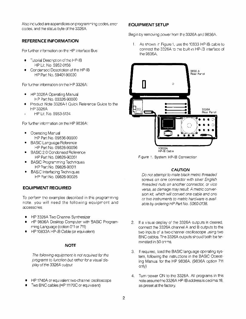
1. As shown in Figure 1, use the 10833 HP-IB cable to connect the 3326A to the built-~n HP-IB interface of the 9836A.
9836 A Rear Panel
Rear Panel
10833A HP-I6 Cable
Figure 1. System HP-IB Connection
CAUTION Do not attempt to mate black metric threaded screws on one connector with silver English threaded nuts on another connector, or vice versa, as damage may result. A metric conver- sion kit, which will convert one cable and one or two instruments to metric hardware is avail- able by ordering HP Part No. 5060-0138.
2. If a visual display of the 3326A outputs is desired, connect the 3326A channel A and B outputs to the two inputs of a two-channel oscilloscope using two BNC cables. The 3326A outputs should both be ter- minated in 50 ohms.
3. If required, load the BASlC language operating sys- tem, following the instructions in the BASlC Operat- ing Manual for the HP 9836A. (9836A option 711 only)
4. Turn power ON to the 3326A. All programs in this note assume the 3326A HP-IB address is decimal 18, as preset at the factory.

To display the current HP-IB address of the 3326A, press the front-panel SHIFT key, followed by the LOCAL key. The address will appear In the 3326A display as:
A d d r . = XX where XX is a number from 00 to 30. inclusive.
If the address is not correct, enter the correct address (18) with the numeric key pad. The address is set and displayed when the second digit is entered.
The nonvolatile memory of the 3326A will retain the address while the instrument is on or off, until another address is entered.
CHECKOUT
If the BASIC operating system has been properly loaded, "BASIC READY" should appear in the 9836A display (option 711 only). If this does not occur, reload BASIC.
The following steps verify that the HP-IB connections and interface are functional:
Press the CLR I10 key of the 9836A to eliminate any possibility of a bus hangup.
Press both the SHIFT and PAUSE keys of the 9836A at the same time to reset the computer.
Type in "SCRATCH" on the 9836A keyboard and press the EXECUTE key. This clears any previous programs from memory.
Type in "REMOTE 7" on the 9836A keyboard and press the EXECUTE key. On the 3326A, both the green REMOTE and yellow LISTEN indicators should be lit.
If these two annunciators are not lit, perform the EQUIPMENT SETUP procedure once again and repeat this CHECKOUT procedure.
If the CHECKOUT procedure fails a second time, look for instrument or controller errors and consult the appropriate manual as listed in the REFERENCE INFORMATION sec- tion of this document.
6. When this checkout procedure passes successfully, type in "LOCAL 7" on the 9836A keyboard, followed by the EXECUTE key. The HP-IB connections and interface are now functional and the programming examples can be performed.
PROGRAMMING EXAMPLES
The following example programs cover a number of basic and advanced topics important in programming the HP 3326A.
Each programming example uses the following format:
A general description of the program and its purpose A program listing Instructions for running the program and an explana- tion of the various sections of the program
EXAMPLE PROGRAM NO. 1 REMOTE, LOCAL, and LOCAL LOCKOUT operation
When operated from its front panel, the 3326A is in the LOCAL mode of operation. All front panel controls are active.
When the 3326A is under program control on the HP-I9 (IEEE-488) bus, LOCAL control is disabled and the front panel is inactive. This is the REMOTE mode of operation. In this mode, the instrument can be restored to front panel con- trol by pressing the LOCAL key or sending a LOCAL com- mand on the HP-IB.
Issuing the LOCAL LOCKOUT command prevents all LOCAL operation and disables the action of the LOCAL key, along with the rest of the 3326A front panel controls. Front ' panel control can only be restored to the instrument by a LOCAL command from the controller.
The following program demonstrates these modes of opera- tion and shows how a variable can be used in a program to define the address of a particular instrument.
RESET the 9836A Type in SCRATCH and press the EXECUTE key to clear any previous programs. Press the EDIT key, then the EXECUTE key, and type in the following program:
1 0 ! REMOTE, LOCAL, LOCAL LOCKOUT DEMO 2 0 ! 3 0 S o u r c e - 7 1 8 4 0 I
5 0 REMOTE S ~ u r c e 6 0 ! 7 0 D 1 5 P " 3 3 2 6 A 1 5 I N REMOTE MOUE" 8 0 ! 9 0 PAUSE 1 0 0 REMOTE S o u r c e 1 1 0 LOCAL LOCKOUT 7 1 2 0 D I S P " 3 3 2 6 A FRONT PANEL LOCKED OUT" 1 3 0 1
1 4 0 PAUSE 1 5 0 LOCAL S o u r c e 1 6 0 D l S P " 3 3 2 6 A FRONT PANEL A C T I V E " 1 7 0 1 8 0 PAUSE 1 9 0 OUTPUT S o u r c e ; "RST" 2 0 0 LOCAL S o u r c e 2 1 0 E N n

PROGRAM 1 -EXPLANATION AND OPERATION
After the program has been entered, RESET the 9836A and press the RUN key to begin execution of the program. No oscilloscope is necessary.
Instead of using the actual instrument address (718), line 30 asslgns the address to a variable that can then be used as a device "name". This makes the program easier to under- stand and if the instrument address changes, only one line of the program need be changed.
Line 50 places the 3326A in the REMOTE mode, and line 70 displays a message to the user on the 9836A CRT. Line 90 pauses execution of the program.
At this point, both the green REMOTE and yellow LISTEN indicators on the 3326A should be lit. Attempt to modify an instrument parameter such as FREQUENCY or AMPLI- TUDE. Verify that all keys except LOCAL are disabled and that an error message is displayed. Press the LOCAL key. The REMOTE annunciator will go out and the 3326A can be operated normally from the front panel.
Press CONTINUE on the 9836A to resume execution of the program. Line 110 places all instruments on the bus in the LOCAL LOCKOUT mode and program execution is paused.
Now verify that the 3326A is again in the REMOTE mode. This time, however, the LOCAL key will not return the instru- ment to front panel control and will generate an error mes- sage. The LOCAL LOCKOUT mode is very useful for pre- venting unwanted changes in parameters or states.
Press CONTINUE on the 9836A to resume execution of the program. Line 150 returns all instruments on the bus to front panel control and program execution is halted. Verify that the 3326A front panel controls are active and that the REMOTE annunciator is extinguished.
CONTINUE the program. In Line 190 an OUTPUT state- ment is used to command the 3326A to perform an INSTRUMENT PRESET (RST). The OUTPUT statement is a very common one in most programs and serves two func- tions-it first places the instrument in the REMOTE mode and then passes information or commands. In line 200 the 3326A is returned to LOCAL control.
EXAMPLE PROGRAM NO. 2 BASIC PARAMETER ENTRY
The majority of programming for the 3326A usually mvolves setting the basic operational parameters such as mode, channel, frequency, amplitude, etc. This program demon-
strates several ways of setting up these parameters with data from the program itself and data entered by the user. This program also covers other topicssuch as autocalibra- tion and the best order for parameter entry.
RESET the 9836A, SCRATCH the memory, and press EDIT and EXECUTE to enter the following program:
I BASIC PARAMETER ENTRY
OUTPUT S o u r c e : "RST , CAL' 1
!CHANNEL A PARAMETER ENTRY: OUTPUT S o u r c e ; "CHA" OUTPUT Source ; "FCNA SQR, FR 1 . 2 3 4 5 KHz" OUTPUT 5 o u r c c ; " A M 2 UO, OF t 1 . 0 5 UO" I
'CHANNEL B PARAMETER ENTRY: OUTPUT Source ; "CHB" OUTPUT Source ; "FCNB S I N ; FR 9876 HZ" OUTPUT S o u r c e j U A M 1 . 0 5 URNS; OF - 0 . 8 UO" LOCAL S o u r c e PAUSE
lSET UP FOR INTERNAL MODULATION OUTPUT Source ; "RST" OUTPUT Source ; "CHA, FR 100 KHz, AN 10 DBM" OUTPUT Source ; "CHB, FR 4 . 0 KHz" OUTPUT S o u r c e ; " A I A ON, CAL" OUTPUT S o u r c e ; " M L 0 PC"
IINTERROGQTE USER FOR INDEX PRINT C H R $ ( 1 2 ) INPUT "ENTER MODULATION INDEX I N PERCENTV, lnde IMAGE "MODULATION LEUEL I S ",ODD.OD," PERCENT" PRINT USING 2 9 0 ; I n d e x IMQGE "ML " ,DOD. DD," PC" OUTPUT S o u r c e USING 3 1 U ; I n d e x GOT0 280 END
PROGRAM 2 -EXPLANATION AND OPERATION
After the program has been entered, RESET the 9836A and press the RUN key to begin execution of the program.
Set up the oscilloscope with channel 1 and 2 sensitivity of 1 Voltidiv. and 0.2 msldiv.
Lines 50 initializes the 3326A. The RST command performs an Instrument preset, leaving the 3326A in a known state. This insures that no previously used parameters or states will be incompatible w~th what is about to be programmed. A calibration is then performed.
In the preset mode that results from the RST command, autocalibration is disabled. If the 3326A is in the AUTOCAL ON mode, the periodic calibrations that are automatically performed may interrupt program execution. By turning these calibrations off and performing them only when nec- essary, such interruptions are prevented.
Lines 80-100 set up channel A. As parameters are entered from the front panel or under program control, the intermedi- ate states that result must not create errors. These errors will cause the improper parameters to be rejected. To guard

against errors, the 3326A is f~rst preset (RST) and param- eters are entered in the following order:
Instrument Mode Channel Output Function Frequency Amplitude Misc. Parameters:
DC Offset Phase Sweep FrequenciesITimes Modulation
Lines 130-150 set up channel B in the same manner as channel A. Several parameters may be sent with a single output statement; simply separate them with a sem~colon, comma, or space.
Line 160 returns the 3326A to LOCAL control so the lnstru- ment state can be examined from the front panel. This is a chance to select a channel and press one of the ENTRY block keys to verify that the 3326A is set up according to lines 90,100,140, and 150 of the program.
Press CONTINUE on the 9836A to resume program execu- tion. Lines 210-220 set the 3326A up for internal modulation with a carrier frequency of 100 kHz and modulation fre- quency of 4 kHz. Line 230 turns internal modulation on and performs a calibration. Modulation level is preset at OO/o in line 240.
Line 270 clears the 9836A display by printing a form feed. Line 280 requests that the user input the modulation index in percent and pauses for the data to be entered.
Enter a modulation index from 0.00 percent to 100.00 per- cent and press CONTINUE.
Lines 290-300 print the desired modulation index on the CRT. The IMAGE statement is used to format the output and round it to two digits to the right of the decimal point.
Lines 310-320 use a similar IMAGE statement to OUTPUT the desired modulation index to the 3326A. The GOT0 statement in line 330 repeats the section of the program that enables the user to enter a new modulation index.
EXAMPLE PROGRAM NO. 3 SWEEP PROGRAMMING
The 3326A can perform a variety of frequency sweeps, with one or both channels. These sweeps are programmed in much the same way as they would be set up from the front panel.
This program demonstrates sweeps in the Two Channel and Two-Phase modes, w ~ t h two different types of sweep triggering.
RESET the 9836A, SCRATCH the memory, and press EDIT and EXECUTE to enter the following program:
! SWEEP PROGRAMMING I
S o u r c e - 7 1 8
OUTPUT S o u r c e ; "RST, CAL'
! SET UP FOR TWO-CHANNEL SWEEP OUTPUT Source ; "CHA; AM 3 . 5 UO" OUTPUT S o u r c e ; " S T 7 5 0 HZ; SP 1 2 . 5 KHz; STIW 1 . 2 5 SEC"
OUTPUT S o u r c e ; "CHBU OUTPUT S o u r c e ; " F C N B SQR; AM 3 UO" OUTPUT S o u r c e ; " S T 1 2 . 5 KHz; SP 7 5 0 HZ" OUTPUT S o u r c e ; "SCU D l S P "CONTINUOUS, TWO-CHANNEL SWEEP" PAUSE
! SET UP FOR TWO-PHASE SWEEP S t o p - f r e q - 1 0 0 0 OUTPUT S o u r c e ; "RST" OUTPUT Source;"MODE TWOP" OUTPUT Source ; "CHA, An 0 OBU" OUTPUT Source ; "CHB, AM 0 OBU, PH - 9 0 DEG" I
OUTPUT S o u r c e j M S M TRGL, S T I M 1 . 5 SEC" OUTPUT S o u r c e ; " S T 5 0 0 H Z , S P U , S t o p - f r e q , " H Z " OUTPUT S o u r c e ; " S T S U D I S P ".TRIGGER SINGLE TWO-PHASE SWEEP" FOR 1 - 1 TO 5
TRIGGER S o u r c e WAIT 1 . 5 TRIGGER S o u r c e WAIT 1 . 5 S t o p - f r e q = S t o p _ C r e q * 2 OUTPUT S o u r c e ; " S P " , S t o p - f r e q , ' H Z b ' NEXT 1
LOCAL S o u r c e END
PROGRAM 3 -EXPLANATION AND OPERATION
After the program has been entered, RESET the 9836A and press the RUN key to begin execution of the program.
Set up the oscilloscope with channel 1 and 2 sensitivity of 1 Voltldiv. and 0.2 msldiv. Experiment with different types of triggering.
Line 90 sets up the 3326A for a sine wave sweep on chan- nel A from 750 Hz to 12.5 kHz with a sweep time of 1.25 sec- onds. The default "ramp" sweep is used, where the instru- ment sweeps from start to stop frequency in the spec~fied time and resets as quickly as possible for the next sweep. Lines 120-130 conf~gure channel B for a square wave sweep over the same limits as channel A. Sweep limits are reversed, however, to yield a downward sweep instead of an upward one.
Line 140 initiates a continuous sweep on both channels and program execution is paused. It is best to view this sweep in the oscilloscope's ALT channel mode with independent trig- gers for each channel. As an alternative, the channels can be viewed separately.

CONTINUE the program to set up the next sweep. Setup for the Two-Phase sweep begins on line 190 where an initial value is established for the stop frequency. In lines 210-230, the 3326A is placed in the Two-Phase mode with equal amplitudes on both channels and a - 90 degree phase off- set for the channel B output. In line 250 the sweep time is set at 1.5 seconds and the sweep mode is "triangle", where sweeps are from the start frequency to the stop frequency and back at equal rates.
Line 260 sets the start frequency at 500 Hz and the stop fre- quency at 1000 Hz, the current value of the variable Stop- freq. This value will be modified by the program later for suc- cessive sweeps. In line 270 the trigger mode of the 3326A is established as "Start Single", where both hardware and software trigger commands will result in single sweeps. In this case, triggers are provided by the selective device trig- ger command "TRIGGER Source" on lines 300 and 320. An alternative is the group execute trigger command "TRIGGER 7". The group execute trigger command will send a simultaneous trigger to all devices on the bus and may be used to start several events at once.
Lines 290-360 form a loop that will repeatedly trigger sweeps in both drections and modify the stop frequency when each sweep is completed. The first trigger command causes the source to sweep upward to the stop frequency and stop, The program pauses for an apporpriate interval to allow the sweep to be completed and sends a second trig- ger command, to cause the 3326A to sweep back to the start frequency.
When each sweep is concluded, lines 340-350 cause the sweep stop frequency to be doubled and a new sweep is initiated. This process is repeated 5 times, once for each execution of the loop. Line 370 returns the 3326A (and any other ~nstruments on the bus) to LOCAL control.
EXAMPLE PROGRAM NO. 4 MODIFYING ENTRY PARAMETERS
Once the operating state of the 3326A has been set up, it is often necessary to modify one or more of the entry param- eters (frequency, amplitude, phase, etc.). This can be done by sending successive new values for these parameters or by using the Entry Increment function.
The Entry Increment function (EINC) sends the 3326A a specific value which will then be used to increment or decre- ment the currently displayed entry parameter. Once the entry increment value has been sent, it is only necessary to send an up (UP) or down (DN) command to change the dis- played parameter.
This technique has two major advantages: First, it is a very convenient way to make repetitive, changes of equal size. Second, it is considerably faster to send a succession of UP or DN commands than to reprogram specific values.
This program demonstrates the EINC function with fre- quency, amplitude, and phase changes.
RESET the 9836A, SCRATCH the memory, and press EDIT and EXECUTE to enter the following program:
1 0 1 MODIFYING ENTRY PARAMETERS I
S o u r c e - 7 1 8 I
OUTPUT S o u r c e j M R S T , CALM
OUTPUT Source ; "CHA AM 4 UO. FR, E INC 250 HZ"
! PERFORM STEPPED FREQ SWEEP FOR 1 - 1 TO 99
OUTPUT S o u r c e j U U P " WAIT .1
NEXT 1 PAUSE I
OUTPUT S o u r c e j f l C H A FR 15 KHz, AM 1 . 5 UO, E I N C 0.1 UO"
! PERFORM STEPPED AMPL SWEEP FOR 1 - 0 TO 3
FOR J-0 TO 25 OUTPUT S o u r c e ; "UP" WAIT .1
NEXT J FOR J-0 TO 25
OUTPUT S o u r c e ;"ON" WAIT .1
NEXT J NEXT I PAUSE
I SET UP FOR TWO-PHASE OPERATION OUTPUT Source ; "RST, MODE TWOP" OUTPUT Source;"CHA FR 2.5 KHz, AM 4 UO" OUTPUT Source ; "CHB AM 4 UO"
360 1 SET ENTRY INCREMENT FOR PHASE 370 OUTPUT Source;"CHB, PH, E INC 30 DEG" 380 ! 390 1 PERFORM PHASE INCREMENT 400 FOR 1-1 TO 100 410 OUTPUT Source ; "ON" 420 WAIT . 2 430 NEXT I 440 EN0
PROGRAM 4-EXPLANATION AND OPERATION
After the program has been entered, RESET the 9836A and press the RUN key to begin execution of the program.
Set up the oscilloscope with channel 1 and 2 sensitivity of 1 Voltldiv. and 0.2 msldiv.
Line 70 sets channel A amplitude and sends a frequency entry increment of 250 Hz. When an entry increment is sent, it must be consistent with the current entry mode of the instrument.
To perform the frequency increment or step, only an UP or DN command is required. Lines 100-130 set up a loop to send the UP command 99 times, with a delay of 0.1 second between commands. The delay slows program execution

enough to allow the 3326A to display the updated fre- quency each time a command is received. The PAUSE instruction then halts program execution.
Note that the use of ElNC allows any frequency increment to be performed rapidly with only a two-letter command.
CONTINUE program execution. Line 160 sets up the 3326A for a 15 kHz, 1.5 Volt sine wave output and an ampli- tude entry increment of 100 mV. Lines 190-280 create two loops nested within a third. The inner loops step the ampli- tude up and then down in 25 steps, thus performing an amplitude sweep. The outer loop causes this sweep to be performed 4 times. The program is once again PAUSED.
Press CONTINUE to resume program execution. Lines 320-340 set the instrument to the TWO PHASE mode with a frequency of 2.5 kHz and an amplitude of 4 Volts on each channel. Line 370 sets a channel B phase entry increment of 30 degrees.
Lines 400-430 decrement channel B phase in 100 steps with a delay of 0.15 seconds between steps.
EXAMPLE PROGRAM NO. 5 DISCRETE SWEEP ENTRY
In the DISCRETE SWEEP mode the 3326A will step through a sequence of user-entered frequencies on both channels. The sequence can contain up to 63 frequency pairs and an associated dwell time for each pair. Dwell times range from 5 milliseconds to 1000 seconds. Sweeps can be either contin- uous or single, and reset at the end of the sweep in either case. The discrete sweep elements can be entered from the front panel or through HP-IB under program control. This program demonstrates the use of an array as one of the most convienent ways of entering these elements with a computer.
In this program the array is structured in a way that makes the function of each array element easy to interpret.
RESET the 9836A, SCRATCH the memory, and press EDIT and EXECUTE to enter the following program:
1 0 G I S C R E T E SWEEP EbiTRY 2 0 O P T I O N BASE 1 3 0 D I N D l s c r i 5 , 3 1 4 0 I
" 0 S o u r c e = 7 1 8 613 1
'0 OUTPUT S o u r c e : " R S T . D C L R , C A L " El0 ! 9 0 1 D I S C R E T E DATH 1 0 0 DATA 5 1 1 0 DATA 1 0 0 0 , 2 0 0 0 , O . ~ 1 2 0 DATA 3 6 0 0 , 1 2 0 0 , 0 . ? " 1 3 0 DATA 2 0 0 0 , 4 0 0 0 , 0 . 3 1 4 0 DATA 6 0 0 0 , 2 0 0 0 ,U .qG
RESTORE 1 0 0 READ Nuni-e I FOR 1 - 1 TO N u m - e l
READ D ~ s c r ( I , l ) , D ~ s c r ( I , 2 ) , D ~ s c r ( I , 3 1 NEXT I
I P R I N T THE ARRAY P R I N T C H R S ( 1 2 ) P R I N T "CH H FREO. CH B FREW. DWELL T I M E ' IMAGE 9 D , 5 X , 9 D . 5 > ' , 5 D . 3 D FOR I = 1 TO Num-e 1
P R I N T U S I N G 2 6 0 : D 1 s c r t l , l l , D i s c r ~ l , 2 ) , D i s c r ~ 1 , 3 1 NEXT I
! SEND ARRHY TO ? 3 2 6 A HS D I S C R E T E PARAMETERS IMAGE ' DSALl " ,ZZ FOR I = l TO Num-e I
OUTPUT S a u r c e ; " C H k , FR " , D i s c r 1 , 1 J , H Z " OUTPUT S o u r c e : " C H B , F R " . G l s c r ( 1 , 2 , ' HZ" OUTPUT 5 0 u r c e ; " S T I M " , O > s c r r I , ? , , ' SEC" OUTPUT S o u r c e U S I N G 3 2 O ; i - 1
NEXT I
, ' SET UP 3 3 2 6 H TO PEPFURM D I S C R E T E W E E P OUTPUT S o u r c e ; " C H A , FCNA SQR. A i l 0 DEU" OUTPUT 5 o u r c e ; " C H B . FCNB S I N , kP1 3 C I B V OUTPUT 5 o u r c e ; " S P l DSCR" I
! I N 1 T I ATE CONTINOUS D I S C R E T E W E E P OUTPUT S o ~ ~ r c e : " S C " END
PROGRAM 5 -EXPLANATION A N D OPERATION
After the program has been entered, RESET the 9836A and press the RUN key to begin execution of the program.
Set up the oscilloscope with channel 1 and 2 sensitivity of 1 Voltidiv. and 0.2 msldiv.
Line 20 specifies the default lower bound of any arrays to follow. Line 30 reserves space in memory for the array of dis- crete sweep parameters to follow. Line 70 presets the 3326A, clears any previous discrete sweep parameters, and calibrates for optimum accuracy.
Lines 100-150 construct a data stream in memory that will be used to fill the array of discrete sweep parameters. The array has 5 rows and three columns. Each row contains two frequencies for channels A'and B, respectively, and an asso- c~ated dwell t~me in seconds. The first data statement (line 100) contains the number of rows in the array.
Line 170 causes the succeeding read statements to begin reading data at line 100. This is a precaution, in case there are any other data statements in the program.
Line 180 reads the first item from the data stream, a count of the rows in the array. This count is used to construct a loop In lines 190-2l0. Each time this loop is executed, it fills a new row in the array, containing channel A and B frequencies and a dwell time.
Line 240 clears the 9836A display and line 250 prints a header for the discrete sweep data to follow. The loop begin- ning in line 270 is executed once to print each row of the array using the image (format) statement in line 260.
1 5 0 DATA 5 0 U 0 , 1 U 0 0 0 , 0 . C l a o I

Lines 340-390 create a loop that assigns elements in the array to appropriate variables and sends them to the 3326A as discrete sweep parameters.
Line 440 sets the 3326A to the DISCRETE SWEEP mode and line 470 initiates a continuous discrete sweep.
EXAMPLE PROGRAM NO. 6 INTERROGATING ENTRY PARAMETERS
Virtually all of the current operating parameters of the 3326A can be interrogated by a computer over HP-IB. Any func- tion that has a numeric value associated with it can be inter- rogated, even if the function is not currently active.
The following program demonstrates the capability of this interrogate function. User-entered frequency, amplitude, and offset parameters are transferred from the 3326A to the computer and displayed.
RESET the 9836A, SCRATCH the memory, and press EDIT and EXECUTE to enter the following program:
! INTERROGATING ENTRY PARAMETERS
LOCAL S o u r c e PRINT C H R I ( 1 2 ) PRlNT "THE 3 3 2 6 6 I S UNDER FRONT PANEL CONTROLL' PRlNT "SET UP R FRONT PANEL STATE (FREQUENCY," PRINT "AMPLITUDE, OFFEST) FOR BOTH CHANNELS" PR lNT "AND PRESS CONTINUE" PAUSE I
! INTERROGATE CHANNEL A PARANETE?S OUTPUT Source;"CHA FR?" ENTER S o u r c s j C h a - f r $ OUTPUT S o u r c e ;"CHA AM?" ENTER Source ;Cha-am$ OUTPUT S o u r c e ;"CHA OF?" ENTER S o u r c s j C h a - o f $ I
I INTERROGATE CHANNEL 8 PfiRWlETERS OUTPUT S o u r c e j " C H 8 FR?" ENTER S o u r c e j C h b - f r $ OUTPUT Source;"CHB AM?" ENTER S o u r c a j C h b - a m $ OUTPUT Source ; "CHB OF?" ENTER S o u r c e j C h b - o f $
! PRINT PARAMETERS PRlNT C H R I ( 1 2 1 PRINT " CHANNEL A CHANNEL 8': PR 1 NT IMAGE K,4X,K PRlNT USING 3 3 0 ; C h a - f r $ , C h b - f r $ PRINT USING 330;Cha_am$,Chb_am$ PRINT USING 3 3 O ; C h a _ o f $ , C h b _ o f $ LOCAL S o u r c e END
PROGRAM 6-EXPLANATION AND OPERATION
After the program has been entered, RESET the 9836A and press the RUN key to begin execution of the program.
Line 50 insures that the3326A is in the LOCAL mode so that the user can set up an instrument state from the front panel. Lines 70-100 print a message to the user. Program execu- tion is halted so that 3326A parameters may be entered.
As suggested by the instructions, enter a frequency, ampli- tude, and offset for each channel from the front panel of the 3326A.
Lines 140-270 interrogate the 3326A for three major param- eters from each channel-frequency, amplitude, and offset. The 3326A is directed to output an entry parameter by selecting a channel and supplying an appropriate prefix fol- lowed by a question mark.
An ENTER command is used to receive the data and assign it to a string variable. String variables preserve any prefixes or suffixes that the 3326A may send with the requested parameter value. An ENTER command must immediately follow each interrogate command to receive the instru- ment's output.
The 3326A always responds with Hertz for frequency val- ues, Volts peak-to-peak for amplitude values, seconds for time values, Volts DC for offset values, degrees for phase and percent for duty cycle. Response for internal modula- tion level is percent or degrees for AM and PM, respectively. In this example, the prefixes, suffixes, and leading and trail- ing zeroes output by the 3326A are all printed. If string vari- ables were not used to enter the data, other print formats could be used to print only the numeric data.
Lines 310-360 print the requested information on the 9836A CRT. The "K,4X,KN format in line 330 prints each complete parameter string without leading or trailing blanks and prints four spaces between the two strings on each line.
EXAMPLE PROGRAM NO. 7 SAVING AND RESTORING A 3326A SETUP
It is often helpful to be able to save a specific instrument setup state or states that will be used later in a test pro- cedure. A state can be saved in one of the 3326A's nine internal registers or it can be transferred to the memory of the 9836A for long term storage.
There are two ways to use the computer to store instrument state data. The individual parameters can be interrogated, (as in the prevlous example program) or the 3326A's LEARN mode may be used to represent the complete instrument state as a compacted string of binary bytes.
Though individual instrument parameters cannot be decoded from the LEARN string, it is afaster and morecom- pact way to represent entire instrument states.
Upon receipt of the LRN command, the 3326A outputs a string of 172 bytes which define an entire setup state. This string can be stored in a computer and later output to the 3326A to restore a setup state.

Th~s program demonstrates the use of the LRN and PRG commands to save and restore a 3326A setup state.
RESET the 9836A, SCRATCH the memory, and press EDIT and EXECUTE to enter the following program:
! SAUING OR RESTORING A 3326A SETUP I
D IM S t a t e $ [ l 7 2 1 S o u r c e - 7 1 8 I
LOCAL S o u r c e PRINT CHR$ ( 12 1 PRINT "THE 3326A I S UNDER FRONT PANEL CONTROL PRINT "SET UP A FRONT PANEL STATE'' PRINT "AND PRESS CONTINUE" PAUSE I RETRIEUE CURRENT INTRUMENT STATE OUTPUT Source ; "SAU 9" OUTPUT S o u r c e ; " L R N 9 " ENTER S o u r c e USING " t , 1 7 2 A " ; S t a t e $ LOCAL S o u r c e PRINT C H R I ( 1 2 ) OISP "CHANGE THE FRONT PANEL STATE"
190 PAUSE 2 0 0 ! RESTORE THE CURRENT INSTRUMENT SATE 210 OUTPUT Source ; "PRG 9 " & S t a t e $ 220 OUTPUT S o u r c e ; " R C L 9 " 230 LOCAL S o u r c e 2 4 0 OISP "INSTRUMENT STATE RESTORED" 250 END
PROGRAM 7 -EXPLANATION AND OPERATION
After the program has been entered, RESET the 9836A and press the RUN key to beg~n execution of the program.
Line 30 reserves space for the string State$. This string holds the binary characters representing the setup state.
Lines 60-100 place the3326A in the LOCAL mode and print a message to set up the 3326A. This state will be stored in the string "State$". Program execution is then paused.
Follow the instructions and set up a distinctive front panel state.
Press CONTINUE. Line 130 causes the setup state to be stored in the 3326A1s internal register 9. The LRN and PRG commands actually operate with the 3326A's internal stor- age registers rather than the current setup state. Once the state is copied in register 9, lines 140-150 send the LRN command to retrieve register 9 and read in the data. The for- mat USING "#,172A" causes the 9836A to read 172 charac- ters for the string and suppresses the requirement for termi- nating conditions (such as the EOI bus management line).
Once the setup state has been stored, Lines 160-180 restore the 3326A to front panel control and instruct the user to change the setup state. At this point the 3326A can also be preset, turned off, or completely cleared.
Press CONTINUE to resume program execution. Line 210 sends the 3326A a command to place the contents of the string "State$" in register 9. Then line 220 recalls register 9 to restore the previous front panel state. Finally, the instru-
ment is restored to LOCAL control and an appropriate mes- sage is displayed on the 9836A CRT. At this point the user can verify that the previous setup state has indeed been restored.
In this same fashion, multiple setup states could be stored in the 9836A and, if desired, saved on disk for later use.
EXAMPLE PROGRAM NO. 8 SERVICE REQUESTS AND ERRORS
Certain errors and operating conditions of the 3326A can be detected and monitored by the 9836A on an interrupt basis or periodically under program control, Included are both programming and hardware errors and instrument condi- tions such as the start or completion of a sweep.
When the desired error or condition exists, the user can con- figure the 3326A to request service from the computer by initiating a Service Request. (SRQ). The computer can detect whether an SRQ has taken place on the bus by ana- lyzing bit l (LSB is bit 0) of its interrupt status register (register 4 on the 9836A built in HP-IB interface).
Two methods can be used to analyze the interrupt status of the 9836A HP-IB interface: The program can periodically read the computer's interrupt status register, or it can enable bit 1 of :he interrupt enable mask (register 5) to interrupt pro- gram execution when an SRQ occurs and bit 1 is set.
In either case, if more than one instrument is on the bus, the computer must conduct a serial poll of all instruments to determine which device requested service. This is done using the SPOLL command and sequentially analyzing the status byte of each instrument that might have generated an SRQ. Under the IEEE-488 definition, the instrument that requires service must have bit 6 of its status byte set.
Once it is determined the 3326A has requested service, the computer can decode the contents of the status byte or, if appropriate, interrogate the error register. A complete description of the status byte and of the error codes are appendices C and B, respectively, of this note. More simply, however, the computer can configure the 3326A to issue an SRQ only when a specific set of errors or operat~ng condi- tions exist. This set of conditions is determined by a numeric value generated by summing the decimal values of each bit to be checked in the status byte. This value is then sent to the 3326A using the MASK command.
The following program demonstrates the use of the SRQ interrupt in the 9836A and the interrupt mask in the 3326A. In addition, the program interrogates the 3326A for the number of an error generated and prints an appropriate message to the user on the 9836A CRT.

RESET the 9836A, SCRATCH the memory, and press EDIT and EXECUTE to enter the following program:
10 1 SERVICE REQUESTS AND ERRORS 20 1
3 0 S o u r c e - 7 1 8 40 ! 5 0 ABORT 7 6 0 CLEAR S o u r c e 7 0 OUTPUT Source ; "MASK 32 PC" 8 0 ENABLE INTR 7;2 9 0 ON INTR 7 GOSUB S r q 100 ' 110 INPUT "ENTER CHANNEL A UOLTAGE I N UOLTS" ,Leve l 120 OUTPUT Source ; "CHA, AM " ; L e u e l ; ' UO" 130 WAIT .1 140 GOT0 110 150 ! 160 S r q : BEEP 170 S t a t u s = S P O L L ( S o u r c e ) 180 PRINT C H R I ( 1 2 ) 190 PRINT " E R R O R D E T E C T E D" 200 OUTPUT S o u r c e ; " E R R ? " 210 ENTER S o u r c e ; U s e r - e r r o r 220 PRINT 230 PRINT "ERROR NUMBER" , U s e r - e r r o r 240 I F B I T ( S t a t u s , O ) THEN PRINT "PROGRAMHING ERROR" 2 5 0 I F B I T ( S t a t u s , l ) THEN PRINT "END OF SWEEP" 260 I F B I T ( S t a t u s , Z ) THEN PRINT "SWEEP I N PROGRESS" 270 I F B I T ( S t a t u s , 3 ) THEN PRINT "HARDWARE ERROR" 290 I F B I T ( S t a t u s , 4 ) THEN PRINT "READY FOR DATA" 290 I F B I T ( S t a t u a , 7 ) THEN PRINT "POWER FAILURE/ON8' 3 0 0 ENABLE INTR 7;2 3 1 0 WAIT 3 320 PRINT C H R I ( 1 2 ) 3 3 0 RETURN 3 4 0 ! 3 5 0 END
PROGRAM 8-EXPLANATION AND OPERATION
After the program has been entered, RESET the 9836A and press the RUN key to begin execution of the program. No oscilloscope is necessary.
Line 50 aborts any current activity on the bus and Line 60 is a selective DEVICE CLEAR command used here to clear the status byte of the 3326A in the event there is an existing SRQ.
Line 70 sends a Service Request MASK to the 3326A ena- bling an SRQ only when bit 5 of the 3326A status byte is set. Bit 5 (decimal value 32) is set when an error condition exists in the 3326A. Line 80 enables program interruption on bit 1 (decimal value 2) of the 9836A status register 5.
Line 90 directs program execution to the subroutine "SRQ" when an SRQ interrupt is generated.
Line 130 delays program execution long enough to allow the 3326A to generate an error (in the event the entered voltage exceeds limits). Without this delay, the program will be directed to line 110 before an SRQ can occur. Line 110 halts program execution to wait for user input and will therefore inhibit interrupt response.
Following the instructions in line 110, enter a channel A amplitude in volts and press CONTINUE. Verify that this level is present in the 3326A display. The program will continue to request voltage inputs until an invalid voltage is entered.
When the program transmits an invalid parameter to the 3326A, an SRQ is generated and line 90 directs program execution to the subroutine "SRQ" beginning on line 160. An audible tone is then generated to alert the user.
Line 170 causes a Serial Poll to be performed and assigns the result to the variable "Status". In the event several instru- ments are present on the bus and an error can be generated by two or more of them, each instrument must be polled individually. The instrment requesting service will have bit 6 of its status byte set and its status byte can be analyzed to determine the cause of the SRQ.
In this case, it is assumed the SRQ is from the 3326A and the MASK statement In line 70 insures that the cause IS a pro- gram or hardware error. The computer, therefore, reads and displays the error in lines 200-230.
Lines 240-290 analyze successive bits of the status byte to determine the condition of the 3326A and print appropriate messages to the user. The interrupt is then re-enabled in line 300 and the user messages are displayed for three seconds. In line 320 the 9836A CRT is cleared and the program returns to ask the user for a new voltage level.
To generate messages such as "End Of Sweep" or "Sweep In Progress", simply enter an invalid Channel A voltage, press the LOCAL key on the 3326A, and initiate a single or continuous sweep before pressing the CONTINUE key.
Line 110 asks the user to enter a channel A output level. This level is sent to the 3326A as an HP-IB command in line 120.

APPENDIX A
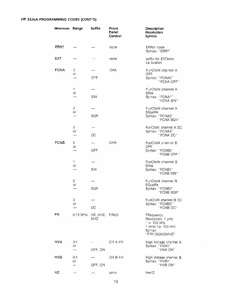
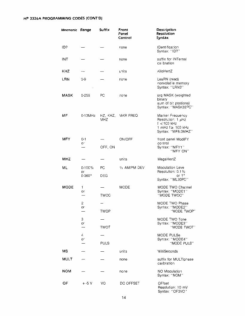
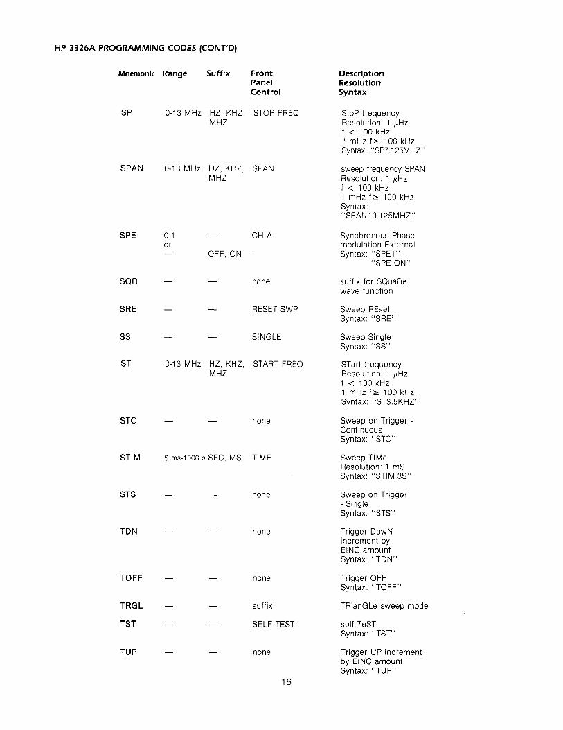
HP 3326A PROGRAMMING CODES
Mnemonic
ACAL
AEA
AEP
AIA
AI P
AM
B EA
BEP
BUSM
CA L
C F
CFM
CHA
CHB
CMB
Range
0-1 0 r -
0-1 or -
0-1 0 r -
0-1 or -
0-1 or -
0-10 v
0- 1 or -
0-1 or -
1-2
-
0-13 MHz
-
-
-
0- 1 0 r
Suffix Front Panel Control
- AUTO
OFF, ON
- CH A
OFF, ON
- CH A
OFF, ON
- CH A
OFF, ON
- CH A
OFF, ON
v o , AMPTD VRMS, DBM, D BV
- CH B
OFF, ON
- CH B
OFF, ON
- none
- MANUAL
HZ, KHz, CNTR FREQ MHz
- M KR- > CF
- CHAN
- CHAN
- COMBINED
- OFF, ON
Description Resolution Syntax
AutoCALibration Syntax: "ACALO"
"ACAL OFF"
Channel A External Am Syntax: "AEAI "
"AEA ON"
Channel A External Pm Syntax: "AEPI "
"AEP ON"
Channel A Internal Am Syntax: "AIA1"
"AIA ON"
Channel A Internal Pm Syntax: "AIPI "
"AIP ON"
AMplitude Resolution: 1 mVpp Syntax: "AM1.125VO"
Channel B External Am Syntax: "BEA1"
"BEA ON"
Channel B External Pm Syntax: "BEPI"
"BEP ON"
BUS Mode Syntax: "BUSM2"
CALibrate Syntax: "CAL"
Center Frequency Resolution: 1 pHz f < 100 kHz 1 mHz f r 100 kHz Syntax: "CF1 OKHZ"
Center Frequency equals Marker value Syntax: "CFM"
select CHannel A Syntax: "CHAM
select CHannel B Syntax: "CHB"
CoMBiner Syntax: "CMBI"
"CMB ON"

HP 3326A PROGRAMMING CODES (CONT'D)
Mnemonic
CMD
COF
DBM
D BV
DC
DCLR
DEG
DN
DRCL
DS AV
DSCR
DISP
DUTY
ElNC
Range
1 or
2 or -
3 or -
-
-
-
-
-
-
-
00-62
00-62
-
0- 1 or -
1-99%
Front Panel Control
SELECT
CLR C#J OFS
units
units
none
RST DISCRETE
units
none
RCL DISCRETE
DISCRETE ST0
none
OFF, ON
PC DUTY CYCLE
see description none
Description Resolutlon Syntax
Calibration MoDe - INTernal Syntax: "CMD1"
"CMD INT"
Calibration MoDe - EXTernal Syntax: "CMD1"
"CMD EXT"
Calibration MoDe - MU LTiphase Syntax: "CMD3"
"CMD MULT"
Clear phase OFfset Syntax: "COF"
DBM
suffix DC function output
Discrete sweep CLeaR Syntax: "DCLR"
DEGrees
DOWN increment by ElNC value Syntax: "DN"
Discrete ReCaLl Syntax: "DRCL02"
Discrete SAVe Syntax: "DSAV02"
Suffix - DiSCRete Sweep Mode
DlSPlay control Syntax: "DISP1"
"DISP ON"
DUTY cycle Resolution: 0.01 % Syntax: "DUTY25.05PCn
Entry INCrement for UP, DN, TUP, and TDN commands Use increment resolution and suffix appropriate for entry value modified Syntax: "EINCI HZ" "EINC.1VRMS"
HP 3326A PROGRAMMING CODES (CONT'DJ
Mnernonlc Range
ERR? -
EXT -
FCNA 0 0 r -
3 or -
FCNB 0 0 r -
Suffix
-
-
-
OFF
-
SIN
-
SQR
-
DC
-
OFF
-
SIN
-
SQR
-
DC
Front Panel Control
none
none
CH A
CH B
F R 0-13 MHz HZ, KHz, FREQ M HZ
H VA 0-1 - CH A HV or - OFF, ON
HVB 0-1 - CH B HV 0 r - OFF, ON
Description Resolution Syntax
ERRor code Syntax: "ERR?"
suffix for EXTernal calibration
FunCtioN channel A OFF Syntax: "FCNAO"
"FCNA OFF"
FunCtioN channel A SlNe Syntax: "FCNAI "
"FCNA SIN"
FunCtioN channel A SQuaRe Syntax: "FCNA2"
"FCNA SQR"
FunCtioN channel A DC Syntax: "FCNA3"
"FCNA DC"
FunCtioN channel B OFF Syntax: "FCNBO"
"FCNB OFF"
FunCtioN channel B SlNe Syntax: "FCNBI "
"FCNB SIN"
FunCtioN channel B SQuaRe Syntax: "FCNB2"
"FCNB SQR"
FunCtioN channel B DC Syntax: "FCNB3"
"FCNB DC"
FRequency Resolution: 1 pHz f < 100 kHz 1 mHz f r 100 kHz Syntax: "FR7.500003MHZ"
High Voltage channel A Syntax: "HVAI "
"HVA ON"
High Voltage channel B Syntax: "HVB1"
"HVB ON"
HZ - - units
HP 3326A PROGRAMMING CODES (CONT'D)
Description Resolution Syntax
Mnemonic Range Suffix Front Panel Control
ID? - - none IDentification Syntax: "ID?"
INT - - none suffix for INTernal calibration
K H z - - units
LRN 0-9 - none LeaRN (read) nonvolatile memory Syntax: "LRN3"
MASK 0-255 PC none srq MASK (weighted binary sum of bit postions) Syntax: "MASK32PCU
0-13MHz HZ, KHz, MKR FREQ MHz
Marker Frequency Resolution: 1 pHz f < I 0 0 kHz 1 mHz f r 100 kHz Syntax: "MF8.0MHZ"
0-1 - ONIOFF or - OFF, ON
front panel ModiFY control Syntax: "MFY1"
"MFY ON"
- - units MegaHertZ
0-1 00% PC '/a AMIPM DEV 0 r 0-360" DEG
Modulation Level Resolution: 0.1 %
or 1" Syntax: "MLSOPC"
MODE 1 - MODE 0 r - TWOC
MODE TWO Channel Syntax: "MODE1" "MODE TWOC"
2 - 0 r - TWOP
MODE TWO Phase Syntax: "MODE2"
"MODE TWOP"
3 - 0 r - TWOT
MODE TWO Tone Syntax: "MODE3"
"MODE TWOT"
MODE PULSe Syntax: "MODE4"
"MODE PULS"
MS
MULT
- - units Milliseconds
suffix for MULTiphase calibration
- - none
NOM NO Modulation Syntax: "NOM"
- - none
+-5 V VO DC OFFSET OFfset Resolution: 10 mV Syntax: "OF3VO"

HP 3326A PROGRAMMING CODES (CONT'D)
Description Resolution Syntax
Mnemonic Range Suffix Front Panel Control
OFF - - none suffix to disable function
ON - - none suffix to enable function
PC - - units
P H +-720" DEG PHASE
Percent
PHase Resolution: 0.01 " Syntax: "PHI 80DEG"
PRG 0-9 - none PRoGrarn (restore) nonvolatile memory Syntax: "PRG3"
PU LS
RAMP
RCL
none
none
RECALL
suffix for PULSe mode
suffix for RAMP sweep
ReCaLl Syntax: "RCL3"
RDY? ReaDY Syntax: "RDY?"
none
REV? REVision Syntax: "REV?"
none
RST INSTR PRESET ReSeT Syntax: "RST"
STORE SAVe Syntax: "SAV3"
CONT Sweep, Continuous Syntax: "SC"
SEC
SER?
units
none
SEConds
SERial number Syntax: "SER?"
SIN suffix for SlNe wave function
TRIANGLE Sweep Mode - linear RAMP Syntax: "SMl " "SM RAMP" RAMP
TRIANGLE Sweep Mode - linear TRianGLe Syntax: "SM2"
"SM TRGL" TRGL
DISCRETE Sweep Mode - DisCRete Syntax: "SM3"
"SM DSCR"
-
DSCR
HP 3326A PROGRAMMING CODES (CONT'D)
Mnemonic Range Suffix Front Panel Control
SP 0-13 MHz HZ, KHz, STOP FREQ MHz
SPAN 0-13 MHz HZ, KHz, SPAN M HZ
SPE 0-1 - CH A or - OFF, ON
SQR - - none
SRE - - RESET SWP
SS - - SINGLE
ST 0-13 MHz HZ, KHz, START FREQ M HZ
STC - - none
STlM 5 rns-1000 s SEC, MS TIME
STS - - none
TDN - - none
TOFF - - none
TRGL - - suffix
TST - - SELF TEST
TU P - - none
Descrlption Resolution Syntax
Stop frequency Resolution: 1 pHz f < 100kHz 1 mHz f r 100 kHz Syntax: "SP7.125MHZN
sweep frequency SPAN Resolution: 1 pHz f < 100 kHz 1 mHz f r 100 kHz Syntax: "SPAN1 0.1 25MHZ"
Synchronous Phase modulation External Syntax: "SPE1"
"SPE ON"
suffix for SQuaRe wave function
Sweep REset Syntax: "SRE"
Sweep Single Syntax: "SS"
STart frequency Resolution: 1 pHz f < 100kHz 1 mHz f r 100 kHz Syntax: "ST3.5KHZU
Sweep on Trigger - Continuous Syntax: "STC"
Sweep TlMe Resolution: 1 mS Syntax: "STIM.3S"
Sweep on Trigger - Single Syntax: "STS"
Trigger DOWN increment by ElNC amount Syntax: "TDN"
Trigger OFF Syntax: "TOFF"
TRianGLe sweep mode
self TeST Syntax: "TST"
Trigger UP increment by ElNC amount Syntax: "TUP"

HP 3326A PROGRAMMING CODES (CONT'D)
Mnemonlc Range Suffix
TWOC - -
TWOP - -
TWOT - -
UP - -
VRMS - -
WAIT - -
ZPH - -
Front Panel Control
none
none
none
none
units
units
none
ASGN ZERO 4
APPENDIX B
HP 3326A HP-IB ERROR CODES
Descriptlon Resolution Syntax
suffix for TWO Channel mode
suffix for TWO Phase mode
suffix for TWO Tone mode
UP increment by ElNC value Syntax: "UP"
VOlts peak-to-peak for amplitude. VOlts dc for dc offset.
Volts RMS for amplitude
no operation Syntax: "WAIT"
Zero PHase Syntax: "ZPH"
DESCRIPTION
HP-IB command has syntax error or contains illegal characters Front panel key pressed while HP 3326A in remote Front panel key pressed while HP 3326A in local lockout Value entered for selected parameter exceeds valid limits In 2 TONE mode, channel B offset frequency greater than 100 kHz Amplitude and dc offset values incompatible Discrete frequency sweep element save nonsequential with existing elements, or instrument state save breaks continuity of discrete frequency elements Marker frequency entered is outside sweep span Frequency value greater than 1 MHz entered w~th high voltage option active

APPENDIX 6. H P 3326A HP-16 ERROR CODES (CONT.)
CODE
26
29
30
40 46 47 50 60 65 70 80 86 8 7
88
89 90 94 95 96 100 110 114 115 116
117 120 130 136 138 140 150 160
170 171 172 173 180 190 191 192 193 194
DESCRIPTION
Frequency value greater than 5 kHz entered with internal PM active, or greater than 100 kHz with internal AM active Combiner is enabled, and nonzero dc offset entered with function other than DC only, or amplitude value greater than half the normal limits In 2 TONE mode with channel B high voltage option enabled, channel B frequency cannot track change to channel A frequency Value that cannot be displayed has been interrogated over the HP-IB Internal modulation enabled and Channel B amplitude or offset selected as display value Channel B phase selected as display value when PULSE mode enabled Units conversion results in zero display value Units key selected improper for parameter selected High voltage opt~on enabled and dBm selected as units Increment value or units incompatible with displayed value Combiner selected but not enabled because current amplitude value is too large Combiner selected but not enabled because Internal AM or PM is enabled 1) In PULSE mode-sine wave output selected, combiner selected, orzero phase assigned tochannel B 2) In 2 CHANNEL, 2 TONE, or PULSE mode-channel B phase offset cleared 3) In 2 TONE, 2 PHASE, or PULSE mode-internal AM or PM selected 4) In 2 CHANNEL mode-synchronous PM selected Internal PM selected with channel B frequency greater than 5 kHz, or internal AM selected with channel B frequency greater than 100 kHz Combiner selected but not enabled because AM or PM enabled Frequency sweep start and stop frequencies are equal for both channels Pulse duty cycle too narrow for sweep range High voltage option enabled and sweep frequency is greater than 1 MHz Channel B frequency exceeds 5 kHz internal PM limit or 100 kHz internal AM limit during sweep Sweep rate less than 5 mHz per second or greater than 0.5 MHz per second No discrete frequency sweep elements exist for discrete frequency sweep Frequency too high for duty cycle requested during discrete frequency sweep High voltage option enabled and discrete frequency sweep element frequency exceeds 1 MHz Channel B frequency exceeds the 5 kHz internal PM limit or 100 kHz internal AM limit during discrete frequency sweep Discrete frequency elements in memory incompatible with selected mode Cannot clear channel A phase offset High voltage option selected and not installed Channel B high voltage option selected with internal modulation High voltage option selected when frequency is greater than 1 MHz A checksum error for recall, learn, or program operation Current instrument configuration incompatible with recalled or programmed state An error is detected in an instrument state recalled from memory and instrument state is replaced with preset state Channel A output is overloaded Channel B output is overloaded SYNC output is overloaded Channel A voltage controlled oscillator IS unlocked HP 3326A cannot lock to external reference signal that is present Unsuccessful internal AM or PM calibration Unsuccessful phase calibration Unsuccessful amplitude calibration Unsuccessful dc offset calibration Unsuccessful residual dc offset calibration
APPENDIX C
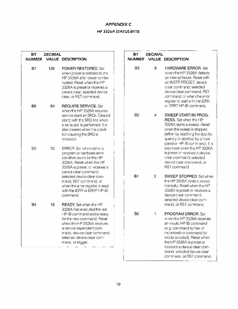
HP 3326A STATUS BYTE
BIT DECIMAL NUMBER VALUE DESCRIPTION
87 128 POWER RESTORED. Set when power IS restored to the HP 3326A after power is inter- rupted. Reset when the HP 3326A is preset or receives a device clear, selected device clear, or RST command.
B6 64 REQUIRE SERVICE. Set when the HP 3326A requires service (sent an SRQ). Cleared along with the SRQ line when a serial poll is performed. It is also cleared when the condi- tion causing the SRQ is removed.
85 32 ERROR. Set when either a program or hardware error condition exists for the HP 3326A. Reset when the HP 3326A is preset, or receives a device clear command, selected device clear com- mand, RST command, or when the error register is read with the IERR or ERR? HP-IB command.
84 16 READY. Set when the HP 3326A has executed the last HP-IB command and is ready for the next command. Reset when the HP 3326A receives a device dependent com- mand, device clear command, selected device clear com- mand, or trigger.
-
BIT DECIMAL NUMBER VALUE DESCRIPTION
B3 8 HARDWARE ERROR. Set when the HP 3326A detects an internal failure. Reset with an INSTR PRESET, device clear command, selected device clear command, RST command, or when the error register is read with the IERR or ERR? HP-IB command.
B2 4 SWEEP STARTIIN PROG- RESS. Set when the HP 3326A starts a sweep. Reset when the sweep is stopped (either by reaching the stop fre- quency or aborted by a front panel or HP-IB command). It is also reset when the HP 3326A is preset or receives a device clear command, selected device clear command, or RST command.
B1 2 SWEEP STOPPED. Set when the HP 3326A ends a sweep normally. Reset when the HP 3326A is preset or receives a device clear command, selected device clear com- mand, or RST command.
1 PROGRAM ERROR. Set when the HP 3326A receives an invalid HP-IB command (e.g. command syntax or incompatible command for mode selected). Reset when the HP 3326A is preset or receives a device clear com- mand, selected device clear command, or RST command

HEWLETT PACKARD
FOR MORE INFORMATION. CALL YOUR LOCAL HP SALES OR SERVICE OFFICE or East (201 I 265-5000 Midwest (31 2) 255-9800 South (404) 955-1 500 West (21 3) 970-7500 or (41 51 968-9200 OR WRITE. Hewlett-Packard, 1820 Embarcadero, Palo Alto, California 94303. I N EUROPE. CALL YOUR LOCAL HP SALES or SERVICE OFFICE OR WRITE, Hewlett-Packard S.A., 7, rue du Bois-du-Lan Case Postale 365 CH 121 7 Meyrin 1 - Geneva, Switzerland. I N JAPAN. Yokogawa-Hewlett-Packard Ltd., 1-27-1 5, Yabe Sagamihara City, Kanagawa Prefecture, Japan 229.
5953-51 35 Printed in U.S.A.