reprinted from: robotics - edcheung.com · yale umrersay. dept. ... such a situation takes place,...
TRANSCRIPT

REPRINTED FROM:
robotics
Volume 10, No. I, 1992
A sensitive skin system for motion control of robot arm manipulators
Edward Che ung * and Vladimir Lumelsky * * Yale Umrersay. Dept. of Electrical E11gmeeri11g. Nell' Hare11. CT 06520, USA
pp. 9-32
north-holland • amsterdam

.;
Robotics a nd Autonomous Systems 10 ( 1992) 9-32 Elsevier
A sensitive skin system for motion control of robot arm manipulators
Edward Cheung * and Vladimir Lumelsky * * Yale Unicersiry, Dept. of Electrical Engineering, New Hacen, CT 06520, USA
Communicated by T.M. Knasel
Abstract
Cheung. E. a nd Lumelsky, Y .. A sensitive skin system for motion control of robot arm manipulators. Robotic~ and Autonomous Systems, 10 (1992) 9- 32.
This work addresses the implementation issues of sensor-based motion planning system for a robot arm manipulator ope ra ting among unknown obstacles of arbit rary shape. In order to realize on-line planning algorithms while protecting the whole arm body from potential collisions with obstacles, the system includes infrared based proximity sensitive skin covering the arm body, compute r hardware for signal processing and motion pla nning, and a n interface between th e planning and arm control systems. These components are described in detail, and their characteristics a re discussed.
Keywords: Sensor-based motion planning; Obstacle avoidance; Sensitive skin; In fra red sensor a rray: Distributed sensing; Motion in unstructured environment; Robot control.
I. Introduction
Current research tn robotic motion planning encompasses two major trends. In one approach complete information about the robot and its environment is assumed. A priori knowledge about the obstacles in the environment is represented by an algebraic description, such as a polyhedral representation.
Another approach, conside red in this paper, assumes incomplete information about the environment. Such a situation takes place, for example, when the robot has no a priori knowledge about the environment, and is equipped with sensors that notify it of impending coll ision, or proximity to an obstacle. Realization of this approach in a robot system requires integration of four basic components: (1) physical sensing ability
* E. Cheung is now at J ackson & Tull, Suite 200, Seabrook, MD 20706. USA.
** Y. Lumelsky is now at the University of Wisconsin, Dept. of Mechanical Engineering, 1513 University Avenue, Madison, WI 53706. USA.
for detecting the presence of obstacles in the environment combined with adequate real-time signal processing and incorporated into an adequa te system architecture, (2) local algorithms for guiding the robot in the vicinity of an obstacle, (3) global algorithms for controlling the general motion so as to avoid infinite cycles and guarantee convergence. This paper addresses the implementation issues that appear in realizing the first component. Issues related to the components (2) and (3) have been discussed elsewhere [1,2] and are outside of our current topic.
Specifically, this paper presents the system architecture and design of a prototype system for sensor-based motion planning of a three-dimensional (3d) robot arm manipulator operating in workspace wi th unknown obstacles. Uses for robot arms equipped with such capabilities include applications for space exploration, work in hazardous, hostile or unhealthy environments, and unstructured factory work cells.
Assuming that, in general, every point of the arm body is subject to potential collisions, one approach to the sensing problem is to cover the
092J -8890j 92j $05.00 © 1992- Elsevier Science Publishers B.Y. All rights reserved

10 E. Cheung, V. Lwnelsk)'
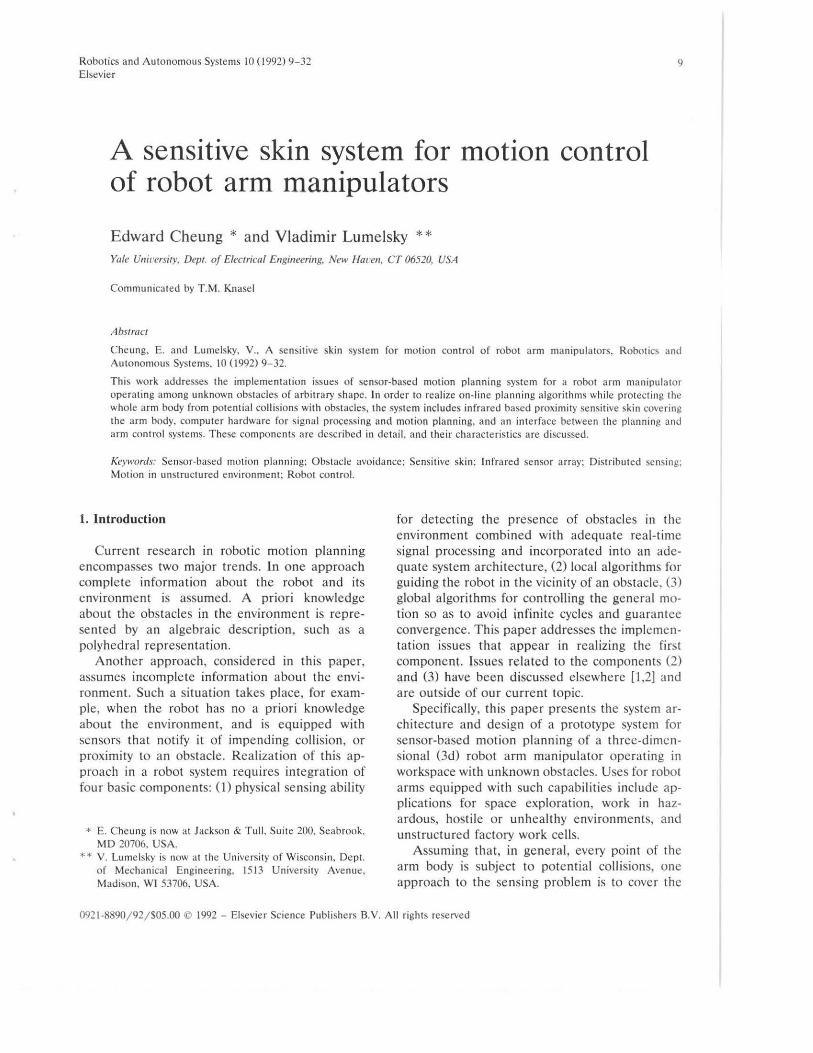
surface of the whole arm with an array of proximity sensors. Obstacles appearing from any direction can then be detected, a nd appropriate actio n take n to avoid them. Such a sensor system based on the infrared light sensi tive skin, together with sensor data interpretation algorithms, has bee n developed at the Yale Univers ity Robotics Laboratory [ 1]. The prototype system is based on an articulated industria l arm manipulator General Electric Model P5 (Fig. 1). Only the arm major linkage that includes the first three links and joints is covered by the motion planning system. In addition to the sensor hardware; software, the assembled system includes several microprocessors in a distributed processor arrangement, an
Edward Cheung received the B.S. degree with high honors from Worcester Po lytechnic Institute in 1985. the M.S. degree and Ph.D. degree from Ya le University in 1985. and 1991. respect ively. Currently, he is a researcher at the NASA Goddard Space Flight Center in Greenbel t. Maryland. H is technical interests include sensorbased robotics. robotic space craft servicing. a nd electronic design.
Vladimir Lumelsky (M '80-SM '83} is c urrently Consolidated Papers Professor of Engineering in the De partment of Mechanical Engineering and Departme nt of Electrical and Computer Engineering, Un iversity of WisconsinMadison. He received his B.S. and M.S. degrees in e lectrical and computer engineering in Le ningrad in 1962. and his Ph.D. degree in applied mathematics from the Institute of Control Sciences (ICS}, U.S.S.R. National Academy of Sciences, Moscow.
in 1970. From 1967 to 1975 be held academic positions in ICS conducting research in pattern recognition. cluster analysis, factor analysis. and control systems, a nd served concu rrently as Adjunct Professor at Moscow Instit ute of Radioelectronics and Automation. From 1976 to 1980 he was on the research staff at Ford Motor Company Scientific Laboratories, Dearborn. Michigan. and from 1980 to I 985 on the research staff at General Electric Corporate Research Center. Schenectady, New York. From 1985 to 1990 he was on the faculty of the Department o f Electrical Engineering at Yale U niversity.
Dr. Lume lsky served as Guest Editor for two special issues o f the IEEE Transactions on Robotics and Automation, on ·Robot Motion Plan ning· and on ·Sensor-Based Intelligent Systems', in J une 1987 and December 1989 respectively, was Program Chairman of the 1989 Inte rnational Worksho p on Intelligent Robots and Systems (l ROS '89} in Tokyo. Japan, and served as a member of the o rga nizing committees of a number of international conferences. He is currently a member o f the Edito ria l Board of the IEEE Transactions on Robotics and AutomMion, a member of the Board of Governors of the IEEE Robotics and Automation Socie ty, and Chairman of the Technical Committee on Robot Motion Planning of the IEEE Robotics and Automatiqn Society. His research interests are in robotics. image processing. pattern recognition. control theory. and industria l automation.
Fig. l. Sketch of the robot arm; j 1, j 2 • j ·' are arm join ts; 12, 13 -
arm links; link 11 is of zero length.
IBM-AT computer as the user inte rface, a nd a Micro Vax workstat ion as the graphica l display device and data logger. Various data handling subroutines imple mented in a parallel processing language operate asynchronously from each other to process the data from the sensors. The overall system block diagram is shown in Fig. 2.
Ideally, the sensitive skin should include the ability to accurate ly detect the distance to any obstacle, regardless of surface texture, color and materia l. I t should have a high noise immuni ty in order to prevent fa lse alarms, and a fast response time to a llow the fastest possible motion of the arm or objects in its e nvironme nt. The entire a rm should be covered so that obstacles approaching from all directions can be detected. The density of sensors along the arm should be sufficiently high to provide unambiguous data about the location of obstacles in the a rm's path. To be resistant against wear and tear, wires that run across the joints of the arm should tole rate constant fl exi ng. Although it is d ifficult to build a sensitive skin having a ll these properties, one can come close e nough by careful design of the system.
The sensitive skin described in detail below uses amplitude modulated infra red light as the sensing medium. The amount of reflected light is used for the proximity ind ication. More complicated methods such as time-of-flight and triangulation we re considered too complex for integration into the sensit ive skin. A more complete comparison of the various choices of sensor types can be found in [2]. In the current prototype system, a n array of about 500 proxi mity sensors is integrated onto a fl exible circuit board which forms the skin surface and is wrapped a round the body of the arm.

Sensor-based motion plannin{! system II
To eliminate the possibility for interference between links, the frequ encies of the light tra nsmitted by the sensors on link I 3 a nd link 12 arc kept at a constant 2: I ratio. Using the demodulation system in the sensor processor circuit, the light t ransmitted by one link's sensors is rejected by the receivers of the o ther link, allowing paralle l sensor operation. In the curre nt impleme ntation, the sensor polling rate is such that the entire skin is polled once every one sixteenth of a second.
The overa ll system shown in Fig. 2 can roughly be divided into three major sections: compute r hardware, robot a rm control syste m, a nd the sensor system. Below, the computer hardware is discussed in Section 2, the robo t arm contro l system in Section 3, and the sensor syste m in Section 4.
2. Computer hardware
The main source of on-line computational power comes from three tra nsputer boards, labeled XPDCS I, XPDCS 2, and 8004 in Fig. 2. In addition, an IBM-AT computer is used as the user interface, and a Micro Yax workstation is used for real-time monito ring, docume nting, a nd the g raphical display.
The transputer board labe led ' 8004' is a product of the I NMOS Corporat ion, manufacture r of the tra nsputer chips. It conta ins 2 megabytes of compute r memory and a T400 transputer rated at about 100 kiloflops. T he development environment runs on this transputer board a nd comm unica tes with the IBM-AT and the Micro Vax. The o the r two transpute r boards are a product of a Yale Robotics Labora tory affili ate [3]. They each conta in 128 kbytes of compute r memory and a T 818 tra nsputer, rated at about 1.2 megaflops. Each transputer can communicate with four high-speed direct me mory access (DMA) serial links that a llow the interconnection of transputers in diffe rent configurations. The high speed links arc also connected to ' link adaptors·, a lso manufactured by !NMOS, which convert the serial links into e ight bit data buses. Data to and from the sensor and robo t control systems are ha ndl ed by these link adaptors.
The board XPDCS 2 pe rforms the low level sensor and robo t inte rface. T hree main subroutines run asynchronously on this board. They ha ndl e the sensor polling, robo t command refreshing, and information excha nge to XPDCS I respectively. This latter board asynchronously runs the subroutines that filter the raw sensor data a nd the sensor inte rpretation (step planning)
Kobot Arm &
Conrro llc r
--------, : Sensor Skin
Fig. 2. Overall system block diagram.
12 E. CheL111g, V Lwne/sky
algori thm. The B004 does the high level motion planning, in addition to interface to the development system (IBM-AT) and graphical display station (Micro Vax).
T he development environment, called Transputer Development System (TDS), is also by INMOS. It includes a text ed itor, compiler, debugger, as well as other utilit ies related to managing a network of parall el processors [4]. Programs that run on the transputers are written in OCCAM, a parallel processing la nguage [5].
T he Micro Vax is connected via a serial connection to the B004 board, and charts the progress of experime nts on its d isplay console. A standalone software package written in C language takes data from the serial port of the Micro Yax and displays the current position of the robot, as well as the history of the experiment. This path and its various projections can be viewed from any direct ion using the uti lities ava ilable in the software package. The display program a lso allows hard copy documentation of the experiments.
3. Robot interface
3.1. Interface architecture
The origi nal robot controller in the GE P5 robot has no provisions fo r host computer interface , and programming the arm for a task can
Commanded position
P--+l c
only be accomplished by point to point ' teaching' of the manipulator using the teach pendant. To implement the sensor-based motion system, an interface between the host computer that houses the planning software and the robot controller has been bu ilt.
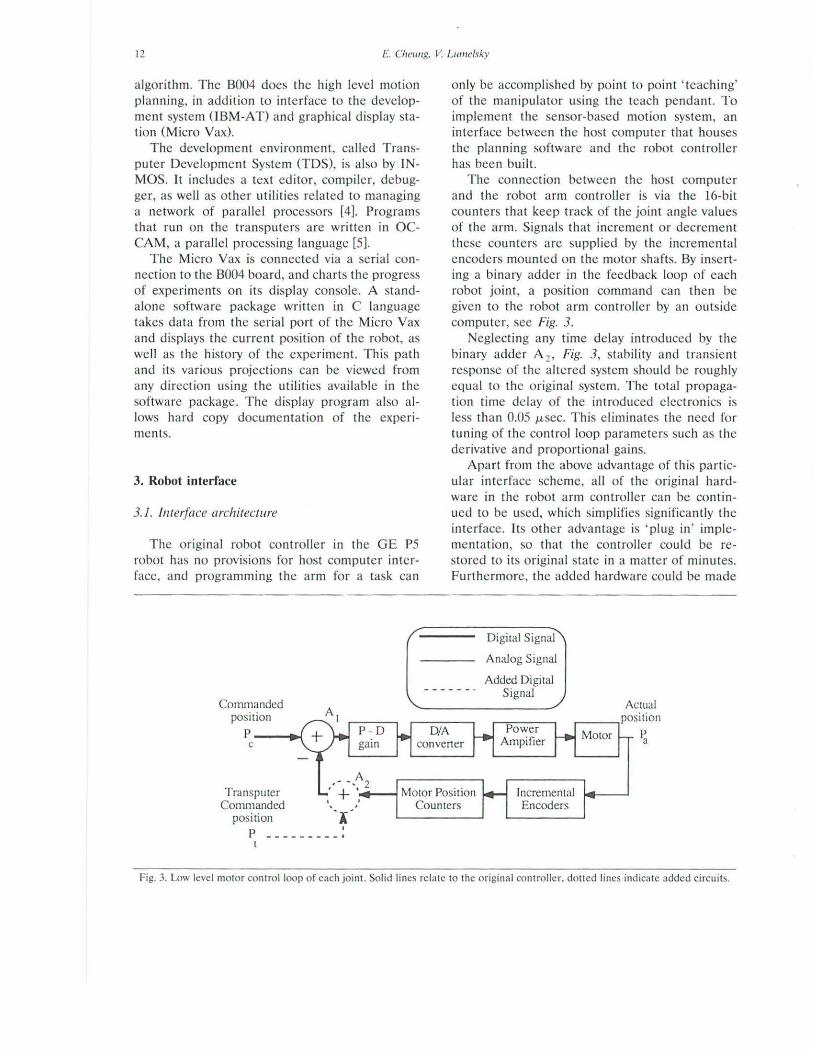
The connection between the host computer and the robot a rm contro ller is via the 16-bit counte rs that keep t rack of the joint angle values of the arm. Signals that increment or decrement these counters are supplied by the incremental encoders mounted on the motor shafts. By inserting a binary adder in the feedback loop of each robot joint, a position command can then be given to the robot arm controller by an outs ide computer, see Fig. 3.
Neglecting any time delay introduced by the binary adder A 2 , Fig. 3, stability and transient response of the altered system should be roughly equal to the original system. The total propagation t ime de lay of the introduced electronics is less than 0.05 J.LSec. This eliminates the need for tuning of the control loop parameters such as the deriva tive and proportional gains.
Apart from the above advantage of this particular interface scheme, all of the original hardware in the robot arm controlle r can be continued to be used, which simplifies significantly the interface. Its other advantage is ' plug in' implementation, so that the controller could be restored to its original state in a matter of minutes. Furthe rmore, the added hardware could be made
Digital Signal
Analog Signal
Added Digital Signal
Transputer Commanded . .
Motor Position Counters
Incremental Encoders
position I p -- - -- -- -- ·
Fig. 3. Low level motor control loop of each joint. Solid lines relate to the original controller. dolled lines indicate added circuits.

Senwr-baJed motion planning l)'stem 13
imperceptible using one toggle switch, a llowing the controlle r to be used as if the new electronics were not install ed . These features arc especially useful at the development stage, e.g. for isolating the sources of malfunctions.
Since only the first three joints (0 1, 0 2, 0 3)
are controlled by the motion planning algorithm, only these contro l loops are affected by the adder interface. The other arm joints can be controlled by the regular means, such as the teach pendant interface. Note that as far as the transputers are concerned the position comma nds are given in an open loop fashion. No feedback of an actual robot position is returned to the transputer. It is assumed that the original robot control loop will position the joint to the commanded position after some settling time, and tha t motion velocities, d0,/dt are relatively low. The adder interface thus effectively transforms the robot into an ope n loop positioning device. Joint velocities can then be commanded by writing a suitable software driver, which, as our pre liminary experiments showed [2], arc sufficie nt for our tasks.
To usc the interface. the robot is first placed by th e robot controlle r in some known position Pc, see Fig. 3. When a command P, is given via
the interface, it will cause the CPU to servo the arm to stabilize the control loop, causing the arm to move to the position P.,, where P,. = Pc- P,. If PC is kept fixed at the origin, 0 I = 0 2 = 0 3 = 0, the arm can be given posit ion commands so that pa = - P,.
3.2. !nteJface hardware
The purpose of the robot interface is to convert signals from the transputer XPDCS 2 into comm ands for the Robot Adder Circuit. The overa ll interface block diagram is shown in Fig. 4. Commands from the transputers are communicated over twisted wire pairs connected to two link adaptors; these are eight bit bidirectional interface chips by !NMOS Corp. One byte (eight bits) rece ived from the transputer is interpreted as the data byte, and the other as the command byte. A sixteen bit Data Bus is generated by demultiplexing the data byte from the link adaptor. Each bit of the control byte, when asserted, triggers an appropria te action in the interface. The functions of each bit arc listed in Table I , and a bit by bit description of the functions of the command byte is given below.
Link Adaptor t-t----~ 8 Bit Latch - - - - 1 "Control"
From RS-4 22 Driver
& T ransputers
L_ Link Adaptor
"Data"
____ ._ T~ist~
wtre patr
---1..,.~ Single signal l ine
---4.,..,. 8 Bit bus
--·--~ 16 Bi t bus
Control Bus
~- - --------- - - -- - - ---------- · Robot Adder Circuit To P-5
(one axis) Computer Bus 1
I
I
16 Bit Latch I
16 Bit Adder
16 Bit Latch II
From Incremental 1 Counter L----- ----- ----------- --- ---Data
Bus
lo
I
To two other axis
Fig. 4. Overall robot inter face block diagram.

14 E. Cheung, V. Lume/sky
When asserted, bit 0 of the command byte causes the link adaptors to send the sixHHm bits present at their collective input lines ' lin' to the transputer, see Fig. 5. This is done by asserting the IValid input on IC3 and IC4. Although these lines are not used in the system, the input data bus was originally wired to implement sending data from the interface to the transputers.
The next bit, bit 1, of the command byte is used to demult iplex the data byte into the sixteen bit Position Data Bus of the robot interface. When this bit is a ' 1', the data byte from the link adaptor is loaded into the octal flip-flop IC7 [7]. The output of the octal flip-flop forms the most significant byte of the Position Data Bus. The least significant byte of the Position Data Bus is
Qval id Qaclc
All JCs connected to +5V and Ground
+5V
RC
Cext
IC4 Control
Qvalid
Dl
+5V
Pos it ion DaUl Bus
Robot Adder Circuit
M-r--------1 Robot E-stop
S 1 - Link adaptor reset
Circuit
Robot Controlle
S2 - Emergency Stop ovcride
IC I - AM26LS32PC, IC2 - AM26LS31 PC, IC3&
Quad Line receiver Quad Line driver
__ .. .,~ Single signal line IC4 - IMSCOI\P-20,
ICS - ECS - 100 AC, JC6 - 74LS122N, IC7 - 74LS273N, IC8 - 74LS244AN,
Link adaptors 5MHz Oscillator Timer CUal flip-flop Octal buffers
Fig. 5. Robot interface circuit d iagram.
I r ... n bit bus
n

Sensor-based m otion planning system 15
formed by the data byte itself. Data from the Position Data Bus can be loaded into the teach pendant interface by asserting bit 2 of the inter-
face. This mode of operation is used to control the remaining arm joints if needed.
Robot Interface
Position Control Data
Bus Bus
Bits 3 through 5 cause the data on the Position
~-----------------------------------------,
I
1 One axis I I I I
fY Carry in L . 0
IC7 Clk f---
Q oc r-1--.'~-'"
1
-l D ICl Q ~..._--! IJw :
A IC3 & IC5 ~
8 bits : Clk Clr Carry out B
- 1-16
high
8 bjts
I
f---.--' 1'- bit X
I I I I I 1.--
I I I
Clk I I I
D I IC2 I I I I I
Clr
Q ~
Carry in B IC4&
A IC6
Carry out L D
not !sed
Robot ~ Controller
XI
li
Q oc r--
IC8 Clk t-----
(note I) 1
lr4 IC9 y I I I
I_ ---------- ------------------------- ---
..--- Note 1: +5V
,. ~ r w
Two other axes
(see note I)
+5Y 4 \OkD
s) Sl - Freeze S2- Clear
~ \0~ I /'
~2 Octal flip-flop 4 bit adder Octal flip-flop
Joint Control bit el bit 5 e2 bit 4 e3 bit 3
Single line
8 bit bus
16bitbus
ICl & IC2- 74LS273, IC3 thru IC6- 74LS283 , IC7 & IC8- 74LS374, IC9 -74LS11, Three input AND gate
XI - 74LS374 Sockets on Counter Board in Robot Controller
IC3 & IC5, IC4 & IC6 cascaded to form an 8 bit adder
Fig. 6. Adder circuit diagram.

16 E. Cheung, V. Lume/sky
Table I Bit funct ions in the command byte (bit 0 is the lea~t significant bit)
Bit Command
0 Link adaptor send I Load high byte of Position Da ta Bus 2 Write teach pendant interface 3 e, position command 4 e2 position command 5 eJ position command 6 Emergency stop override 7 Not used (spare)
Data Bus to be loaded into the adde rs pertaining tO jointS 6 I through 6 3 respectively, and CaUSeS the writ ing of a position command. The decimal number represented by the data on the Position Data Bus is the two's complement re presentation of an integer value proportional to the commanded joint angle in degrees. The proportionality constant depends on the e ncoder pulses per motor revolution and the gearing between the motor shaft and the jo int.
The next bit, bit 6, bypasses the a utomatic emergency stop circuit. Whe n this bit is a ' 1' , the so-called ' watch dog circuit' is disabled. Th is system will be explained in more de tai l below.
T he circuit that performs the robot interface is shown in Fig. 5. The circuit is connected to the transputers by a twisted wire pair to increase the no ise immunity. The main chips in the interface circuit, link adaptors IC3 a nd IC4, are connected to ICl and IC2, which convert the signals from RS422 protocol to single e nded TTL level signals. T he output of IC3, which forms the data byte, is buffered by IC8, and forms the least significant byte of the Position Data Bus. It is also connected to the input of IC7, which latches the most significant byte of the Position Data Bus when bit 1 of the command byte is asserted. The output of IC4 forms the 8 bit command bus of the interface. Each bit of the command byte controls a particular function as explained above.
Every 15 msec, the transputer XPDCS 2 writes a position comma nd to the interface; thus all three joints receive a new position command at that interval. At the arrival o f a new byte, the link adaptors assert their respective 'QYalid' signal. Using a suitably designed circuit, this s ignal can be utilized for the purpose of mon itoring the
status of the transpute r. Th is ' watch dog' circuit is formed by IC6, a retriggerable multivibra to r. Its 'Q ' output stays high if pulses a rrive at its ' BJ' input that arc spaced sufficiently close in time. T his minim um spacing is set by the variable resistor connected to its ' RC' input. If the 'Q ' output of IC6 cha nges sta te to a low vol tage level, relay R I will interrupt curre nt flow in the robot controller's emergency stop circuit, which causes the servos to switch off, and the brakes of the robot arm to be e nergized. The a rm will stay in this disabled state until the emergency stop circuit is again closed, and a front pa nel reset switch is pushed. This feat ure can be bypassed in software by asserting bit 6 of the command byte. In this case, the relay will remain energized even if the transputer connected to the robot interface crashes. In series with R I and S2 is the so-called 'chicken switch' (not shown in the circuit d iagram), wh ich can be operated manually. Actuating this switch interrupts current flow in the emergency stop circuit, and can be used for an emergency stop in the case of a malfunction during testing.
Fig. 6 shows the circuit diagram of the binary adder part of the robot interface. It converts commands from the Robot Interface Circuit to data which it inserts in to the low level robot feedback loops. ' Breaking into' the robot controller began by removing the chips that contain the registers which keeps track of the joint values of the arm. The chips arc on the circuit board inside the motor controlle r called the Counter Board. Cables were installed in place of the chips, which jumpered all the necessary signals from the Counter Board to the Adder Inte rface Circuit board. The o riginal registers that we re removed from the Counter Boa rd were then placed on the Adder Interface board, with the binary adders inserted in series with the da ta path. The binary adders used were 4 bit full adders, thus four were used per jo int (IC3 through IC6 on Fig. 6). The registers that were removed from the Counter Board are IC7 through IC8 for the joint shown.
Table 2 illust rates how data are loaded into the binary adders, and thus given to the robot controlle r. The sequence shows the data (in Hex) on the data and command bus of the robot interface during a load of the number 325(Hex) into the adder for joint 6 1• This corresponds to a value of about 5° for 6 1.