representing and rendering distant objects for … · representing and rendering distant objects...
TRANSCRIPT

Dissertation
Representing and Rendering Distant Objectsfor Real-Time Visualization
ausgefuhrtzum Zwecke der Erlangung des akademischen Grades
eines Doktors der technischen Wissenschaften
unter der Leitung vonAo.Univ.Prof. Dipl.-Ing. Dr.techn. Michael Gervautz,Institut 186 fur Computergraphik und Algorithmen,
und unter Mitwirkung vonUniv.-Ass. Dipl.-Ing. Dr.techn. Dieter Schmalstieg
eingereichtan der Technischen Universitat Wien,
Fakultat fur Technische Naturwissenschaften und Informatik,
vonDipl.-Ing. Michael Wimmer,Matrikelnummer 9225135,
Veronikagasse 42/14,A-1170 Wien, Osterreich,
geboren am 23. Dezember 1973 in Wien.
Wien, im Juni 2001.
Michael Wimmer (PhD Thesis)
Representing and Rendering Distant Objectsfor Real-Time Visualization
http://www.cg.tuwien.ac.at/research/vr/urbanviz/mailto:[email protected]
reviewer:Michael GervautzFrancois X. SillionDieter Schmalstieg
Abstract
Computer graphics is the art of creating believable images. The difficulty in manyapplications lies in doing so quickly. Architectural walkthroughs, urban simula-tion, computer games and many others require high-quality representation of verylarge models at interactive update rates. This usually means creating a new imageat least 60 times a second. This is what real-time visualization is about.
This thesis presents two methods to accelerate the rendering of very large vir-tual environments. Both algorithms exploit a common property of many suchenvironments: distant objects usually take up a significant amount of computationtime during rendering, but contribute only little to the final image. This thesisshows how to represent and render distant objects with a complexity proportionalto the image area they cover, and not to their actual complexity. The algorithmsare destined for different scenarios: the first is an online algorithm that carries outall computation during runtime and does not require precomputation. The secondalgorithm makes use of preprocessing to speed up online rendering and to improverendering quality.
The first part of the thesis shows an output-sensitive rendering algorithm foraccelerating walkthroughs of large, densely occluded virtual environments usinga multi-stage image-based rendering pipeline. In the first stage of the pipeline,objects within a certain distance (the near field) are rendered using the traditionalgraphics pipeline. In the following stages, the remainder of the scene (the farfield), which consists of all pixels not yet covered by near-field geometry, is ren-dered by a pixel-based approach using a panoramic image cache, horizon estima-tion to avoid calculating sky pixels, and finally, ray casting. The time complexityof the approach does not depend on the total number of primitives in the scene. Wehave measured speedups of up to one order of magnitude compared to standardrendering with view-frustum culling.
In the second part of the thesis, a new data structure for encoding the appear-ance of a geometric model as seen from a viewing region (view cell) is presented.This representation can be used in interactive or real-time visualization applica-tions to replace complex models—especially distant geometry—by an impostor,maintaining high-quality rendering while cutting down on rendering time. The ap-proach relies on an object-space sampled representation similar to a point cloud ora layered depth image, but introduces two fundamental additions to previous tech-niques. First, the sampling rate is controlled to provide sufficient density acrossall possible viewing conditions from the specified view cell. Second, a correct, an-tialiased representation of the plenoptic function is computed using Monte Carlointegration. The system therefore achieves high-quality rendering using a simplerepresentation with bounded complexity.
i

This thesis also contains a comprehensive overview of related work in thefield of real-time visualization, and an in-depth discussion of the advantages anddisadvantages of image-based and point-based representations for distant objects.
ii
Kurzfassung
Computergraphik ist die Wissenschaft, die sich mit der Generierung glaubwurdi-ger Bilder beschaftigt. Eine der großten Herausforderungen dabei ist, diese Bilderin ausreichender Geschwindigkeit zu erzeugen. Speziell bei der Simulation vonFahrzeugen in Stadtgebieten, bei der virtuellen Erforschung von Gebauden (obnoch nicht gebaute, existierende oder schon lange zerstorte), bei Computerspielenund vielen anderen Anwendungen ist es wichtig, daß die Bilder in flussiger Abfol-ge erscheinen. Ublicherweise versteht man darunter eine Bildrate von mindestens60 Bildern pro Sekunde. Das ist das Thema der Echtzeitvisualisierung.
In dieser Dissertation werden zwei Algorithmen zur beschleunigten Darstel-lung von großen virtuellen Szenen vorgestellt. Dabei wird bei beiden Algorith-men eine interessante Eigenschaft von vielen solchen Szenen ausgenutzt: Objekte,die sich weiter weg vom Betrachter befinden, machen nur einen kleinen Teil desendgultigen Bildes aus, benotigen aber relativ viel Rechenzeit. In dieser Disserta-tion wird gezeigt, wie man entfernte Objekte mit einer Komplexitat, die der uber-deckten Bildflache – und nicht ihrer eigentlichen geometrischen Komplexitat –entspricht, reprasentieren und darstellen kann. Die beiden Algorithmen sind furunterschiedliche Szenarien gedacht. Die erste Methode funktioniert zur Laufzeit,braucht also keine Vorberechnung. Die zweite Methode hingegen hat einen wich-tigen Vorberechnungsschritt, der bei der Darstellung sowohl die Geschwindigkeitals auch die Qualitat signifikant erhoht.
Der erste Teil der Dissertation beschaftigt sich mit einem Algorithmus zurDarstellung von Szenen mit starker gegenseitiger Verdeckung von Objekten. Da-bei kommen in mehreren Schritten bildbasierte Renderingmethoden zum Einsatz.Objekte bis zu einer bestimmten Entfernung vom Betrachter werden mit gewohn-lichen polygonbasierten Methoden gezeichnet. In einem weiteren pixelbasiertenSchritt werden dann alle noch nicht bedeckten Pixel des Bildes identifiziert undin einem zylindrischen Zwischenspeicher fur Farbwerte nachgesehen. Sollte dortkein sinnvoller Wert vorhanden sein, wird die Farbe des Pixels mittels eines Blick-strahls ermittelt, sofern sich das Pixel nicht uber dem Horizont befindet. Die Me-thode funktioniert praktisch unabhangig von der Anzahl der verwendeten Objektein der Szene und erreicht eine bis zu zehnfache Beschleunigung im Vergleich zuublichen Darstellungsmethoden.
Im zweiten Teil der Dissertation wird eine Datenstruktur zur getrennten Spei-cherung von Geometrie- und Farbinformationen fur ein Objekt prasentiert, geeig-net fur die Betrachtung aus einem bestimmten raumlich abgegrenzten Bereich.Damit sollen komplexe Objekte in virtuellen Szenen – insbesonders weit entfern-te Objekte – ersetzt werden, um eine schnellere und qualitativ bessere Darstellungdieser Objekte zu erreichen. Dabei wird das Objekt quasi mit einer Punktwolke
iii

dargestellt, deren Dichte sich nach den moglichen Betrachterpositionen richtet.Das Aussehen der Punktwolke wird mittels eines Monte Carlo Verfahrens be-stimmt, das eine artefaktfreie Darstellung von allen erlaubten Blickpunkten ausgestattet.
Außerdem gibt diese Dissertation einen ausfuhrlichen Uberblick uber schonpublizierte Methoden im Bereich der Echtzeitvisualisierung, und enthalt eine Ana-lyse uber Vor- und Nachteile von bild- und punktbasierten Renderingmethoden furdie Darstellung von entfernten Objekten.
iv
Acknowledgements
This thesis would not have been possible without the help of many people: I wouldlike to thank my advisor, Michael Gervautz, for bringing me into the wonderfulresearch group at Vienna. I owe thanks to Dieter Schmalstieg, who introduced meduring many discussions to the peculiarities of scientific research, and who super-vised the first part of this thesis. The second part of the thesis was supervised byFrancois Sillion, who never failed to bring the work on track in critical situations.
Many of the ideas leading to the first part of the thesis are directly attributableto Markus Giegl, who also kindly let me use his ArsCreat programming frame-work to implement the method. I equally want to thank his wife, Gabi, for design-ing a test model for this part of the work.
The second part of this thesis is the direct result of endless discussions, throw-ing around ideas, filling one drawing board after the other, and generally workingtogether, with my colleague Peter Wonka. He also provided the test model forthe walkthroughs shown in the second part of the thesis. This model also prof-ited greatly from the dedicated work of our students: thanks to Gregor Lehningerand Christian Petzer for tree models, Paul Schroffenegger for an automatic roofgenerator, and Gerald Hummel for providing a street generation tool.
Finally, I wish to thank all people of the research group in iMAGIS, Grenoble,where I spent six months working on the thesis, and the research group in Vienna,where I spent the rest of my time.
Part of this research was supported by the Austrian Science Fund (FWF) con-tract no. P13867-INF and P11392-MAT, and by the EU Training and Mobilityof Researchers network (TMR FMRX-CT96-0036) “Platform for Animation andVirtual Reality”.
v
Contents
Abstract i
Kurzfassung iii
Acknowledgements v
1 Introduction 11.1 The evolution of real-time rendering . . . . . . . . . . . . . . . . 11.2 Problem statement . . . . . . . . . . . . . . . . . . . . . . . . . 21.3 Thesis statement . . . . . . . . . . . . . . . . . . . . . . . . . . . 31.4 Proposed solutions and chapter layout . . . . . . . . . . . . . . . 31.5 Contributions . . . . . . . . . . . . . . . . . . . . . . . . . . . . 41.6 Motivations . . . . . . . . . . . . . . . . . . . . . . . . . . . . . 51.7 Individual publications about this work . . . . . . . . . . . . . . . 5
2 Related Work 72.1 Definition and goals of real-time rendering . . . . . . . . . . . . . 72.2 The traditional pipeline, standard acceleration techniques . . . . . 9
2.2.1 Visibility Culling . . . . . . . . . . . . . . . . . . . . . . 112.2.2 Levels of Detail . . . . . . . . . . . . . . . . . . . . . . . 15
2.3 Image-based rendering . . . . . . . . . . . . . . . . . . . . . . . 192.3.1 The Plenoptic function . . . . . . . . . . . . . . . . . . . 202.3.2 Light fields . . . . . . . . . . . . . . . . . . . . . . . . . 212.3.3 Quicktime VR and View Interpolation . . . . . . . . . . . 222.3.4 Images as approximation, impostors . . . . . . . . . . . . 232.3.5 Images as caches . . . . . . . . . . . . . . . . . . . . . . 242.3.6 Enhancing images with depth . . . . . . . . . . . . . . . 252.3.7 Impostor meshes . . . . . . . . . . . . . . . . . . . . . . 26
2.4 Point-based rendering . . . . . . . . . . . . . . . . . . . . . . . . 282.5 Ray tracing . . . . . . . . . . . . . . . . . . . . . . . . . . . . . 30
2.5.1 Ray casting . . . . . . . . . . . . . . . . . . . . . . . . . 31
vi
2.5.2 Complexity bounds . . . . . . . . . . . . . . . . . . . . . 322.6 Mathematical tools . . . . . . . . . . . . . . . . . . . . . . . . . 33
2.6.1 Bases and their duals . . . . . . . . . . . . . . . . . . . . 332.6.2 Monte Carlo integration . . . . . . . . . . . . . . . . . . 352.6.3 Sampling theory and antialiasing . . . . . . . . . . . . . . 36
2.7 Discussion . . . . . . . . . . . . . . . . . . . . . . . . . . . . . . 37
3 Motivation—General Terms 393.1 Near field and far field . . . . . . . . . . . . . . . . . . . . . . . 393.2 Online and offline calculation . . . . . . . . . . . . . . . . . . . . 403.3 Notation of vectors in this thesis . . . . . . . . . . . . . . . . . . 41
4 Ray Casting with Image Caching and Horizon Tracing 434.1 Introduction . . . . . . . . . . . . . . . . . . . . . . . . . . . . . 434.2 System overview . . . . . . . . . . . . . . . . . . . . . . . . . . 454.3 Ray casting . . . . . . . . . . . . . . . . . . . . . . . . . . . . . 46
4.3.1 Near field / far field . . . . . . . . . . . . . . . . . . . . . 464.3.2 Ray casting . . . . . . . . . . . . . . . . . . . . . . . . . 48
4.4 Image caching . . . . . . . . . . . . . . . . . . . . . . . . . . . . 494.4.1 Panoramic image cache . . . . . . . . . . . . . . . . . . . 494.4.2 Cache update strategy . . . . . . . . . . . . . . . . . . . 51
4.5 Horizon tracing . . . . . . . . . . . . . . . . . . . . . . . . . . . 534.6 Results . . . . . . . . . . . . . . . . . . . . . . . . . . . . . . . . 554.7 Discussion—advantages and shortcomings . . . . . . . . . . . . . 58
4.7.1 Scalability . . . . . . . . . . . . . . . . . . . . . . . . . 584.7.2 Aliasing . . . . . . . . . . . . . . . . . . . . . . . . . . . 59
4.8 Applications . . . . . . . . . . . . . . . . . . . . . . . . . . . . . 594.8.1 Walkthroughs . . . . . . . . . . . . . . . . . . . . . . . . 594.8.2 Computer Games . . . . . . . . . . . . . . . . . . . . . . 604.8.3 Portal Tracing . . . . . . . . . . . . . . . . . . . . . . . . 604.8.4 Effects . . . . . . . . . . . . . . . . . . . . . . . . . . . 61
5 Point-Based Impostors 635.1 Introduction . . . . . . . . . . . . . . . . . . . . . . . . . . . . . 635.2 Overview of the algorithm . . . . . . . . . . . . . . . . . . . . . 655.3 Point-Based Impostors . . . . . . . . . . . . . . . . . . . . . . . 66
5.3.1 Complexity of appearance . . . . . . . . . . . . . . . . . 665.3.2 Geometric sampling . . . . . . . . . . . . . . . . . . . . 685.3.3 Appearance: the plenoptic image function . . . . . . . . . 69
5.4 Implementation . . . . . . . . . . . . . . . . . . . . . . . . . . . 725.4.1 Obtaining geometric samples . . . . . . . . . . . . . . . . 72
vii
5.4.2 Monte Carlo integration of radiance fields . . . . . . . . . 755.4.3 Compression and Rendering . . . . . . . . . . . . . . . . 76
5.5 Results . . . . . . . . . . . . . . . . . . . . . . . . . . . . . . . . 765.6 Discussion . . . . . . . . . . . . . . . . . . . . . . . . . . . . . . 79
6 Conclusions and Future Work 836.1 Synopsis . . . . . . . . . . . . . . . . . . . . . . . . . . . . . . . 846.2 Advantages . . . . . . . . . . . . . . . . . . . . . . . . . . . . . 84
6.2.1 Specific advantages of point-based impostors . . . . . . . 856.3 Disadvantages and limitations . . . . . . . . . . . . . . . . . . . 866.4 Future work . . . . . . . . . . . . . . . . . . . . . . . . . . . . . 88
6.4.1 Triangle-based impostors . . . . . . . . . . . . . . . . . . 886.4.2 View cell partitioning . . . . . . . . . . . . . . . . . . . . 896.4.3 Near-field and far-field distance . . . . . . . . . . . . . . 89
6.5 Conclusion . . . . . . . . . . . . . . . . . . . . . . . . . . . . . 90
Bibliography 91
Curriculum vitae 109
viii
List of Figures
4.1 Ray casting screenshot . . . . . . . . . . . . . . . . . . . . . . . 444.2 Diagram of traditional rendering pipeline . . . . . . . . . . . . . 454.3 Diagram of extended image-based pipeline . . . . . . . . . . . . 464.4 Image cache diagram . . . . . . . . . . . . . . . . . . . . . . . . 464.5 Indexing into the panoramic image cache . . . . . . . . . . . . . 504.6 Image cache data structure . . . . . . . . . . . . . . . . . . . . . 524.7 Horizon tracing . . . . . . . . . . . . . . . . . . . . . . . . . . . 544.8 Results for hardware rendering and ray casting . . . . . . . . . . 554.9 Results for different near-field distances . . . . . . . . . . . . . . 574.10 Ray casting results for 320x240 . . . . . . . . . . . . . . . . . . 584.11 Overview of test model for ray casting . . . . . . . . . . . . . . . 614.12 Screen shot of test model for ray casting . . . . . . . . . . . . . . 62
5.1 Urban walkthrough shot with point-based impostor . . . . . . . . 635.2 Placement of perspective LDI cameras . . . . . . . . . . . . . . . 665.3 Ray casting from the sampling plane . . . . . . . . . . . . . . . . 675.4 Microgeometry . . . . . . . . . . . . . . . . . . . . . . . . . . . 675.5 Parameters of the plenoptic image function . . . . . . . . . . . . 695.6 Arrangement of impostor, view cell, cameras, sampling plane . . . 735.7 2D sampling analogon . . . . . . . . . . . . . . . . . . . . . . . 735.8 Resampling factor for rotations . . . . . . . . . . . . . . . . . . . 745.9 Point removal . . . . . . . . . . . . . . . . . . . . . . . . . . . . 755.10 Finding the texture matrix for hardware rendering . . . . . . . . . 775.11 Example of a packed impostor texture . . . . . . . . . . . . . . . 785.12 Impostor and view cell placement example in a city . . . . . . . . 805.13 Impostor example: building front with trees . . . . . . . . . . . . 815.14 Impostor example: city shot . . . . . . . . . . . . . . . . . . . . 825.15 Impostor in urban walkthrough . . . . . . . . . . . . . . . . . . . 82
ix

List of Tables
4.1 Pixel statistics for ray casting . . . . . . . . . . . . . . . . . . . . 57
5.1 Impostor statistics for 3 point-based impostors . . . . . . . . . . . 79
x
Chapter 1
Introduction
1.1 The evolution of real-time rendering
Computer graphics is an ever evolving field. Years ago, researchers concentratedon rendering appealing still images. Ray tracing and radiosity were developed tocreate images which mimick real photographs, giving rise to “photorealistic ren-dering”. Applications of photorealistic rendering are manifold, including lightingsimulation of planned buildings, creating artwork, and not the least of them isrendering effects and whole image sequences in the movie industry.
Yet, many users did not content themselves with single images which took inthe range of minutes or even hours to compute. Many application areas calledfor interactive image generation. Early systems were very plain, presenting theuser with wireframe views of a scene, barely sufficient to form a notion of thespatial relationship of objects. The potential of interactive techniques was soondiscovered, however, and a huge effort was dedicated to creating systems of bothhigher display speed and higher image quality. A new research direction wasborn: “real-time rendering”. Flight simulation, driving simulation, architecturalwalkthroughs, interactive modeling packages and virtual reality were among theapplications that benefited from or even were inspired by the advances made inreal-time rendering.
Yet as interactive graphics systems got faster and faster, the expectations andrequirements of such systems grew at an even faster pace. While early applicationsoffered manipulation of some simple objects, it was soon expected to see terrainflythroughs and car simulations with considerably increased complexity, whiletoday’s applications try to display full-fledged city models with realistic lightingand full real-time, interactive car simulations.
1
Chapter 1 Introduction
In recent years, the popularity of three-dimensional computer games has givenan unexpected boost to consumer graphics hardware, starting with the introductionof the 3DFX Voodoo graphics card in 1997 [Leht00]. Relatively cheap graphicboards are now threatening to overtake expensive workstation hardware in speedas well as in quality. Practically all newly sold personal computers come withconsiderable graphics capabilities.
While recently introduced graphics boards promise to achieve near photore-alistic image generation in real-time, the sheer complexity and size of today’smodels still tends to be overwhelming for contemporary hardware, and a lot ofresearch has been invested into finding ways to deal with that complexity on ahigher level, making use of a priori knowledge about the given models.
This thesis is about one such approach, which is apt to reduce the renderingtime for very complex models, while at the same time improving their visual qual-ity.
1.2 Problem statement
Interactive computer graphics applications are used in many fields, but most ofthem can be summarized in three categories:
• Indoor exploration: the user navigates inside a building or similar closedenvironment, like a cave system.
• Outdoor exploration: the user walks, drives or flies over an outdoor envi-ronment like a city or a terrain.
• Object manipulation: the user interactively manipulates a virtual object likea prototype of a car or a manufacturing part.
Of these three categories, the first two offer an interesting challenge: while therequirements on display speed and image quality are very stringent, indoor andoutdoor scenes feature practically unbound complexity, making it very difficultto meet such requirements. Even a very modest city model, for example, whereindividual buildings consist of not more than a few hundred triangles, total sev-eral million triangles. Walkthrough and simulation applications, however, usuallydemand frame rates high enough to match the display update rate (between 60and 85 Hz). Modern graphics accelerators may display several million trianglesper second, but this does not suffice to display large models at an update rate of
2
Chapter 1 Introduction
60 times per second, and models have not reached their peak of complexity forlong.
Besides performance, large environments pose another problem: distant ob-jects, although of the same complexity as foreground objects, are perceived ona much smaller area on the screen as foreground objects. Therefore, the screenresolution is not sufficient to display distant objects in their full detail. Currentrendering algorithms have to subsample distant objects, leading to spatial andtemporal aliasing. This creates a noticeable image quality problem.
Fortunately, models in one of the mentioned categories are structured andshare some interesting aspects: due to the nature of perspective (which makes nearobjects appear large and far objects appear small) and occlusion (which causesmany objects to be hidden by other objects in any given view) only a very smallnumber of objects account for covering most of the pixels on the screen.
The problem treated in this thesis is how to exploit this particular property ofvirtual environments to improve both frame rates and image quality.
1.3 Thesis statement
This research presents a set of algorithms to exploit the specific structure of manyvirtual environments in order to obtain higher frame rates and better image quality.
The central thesis of this research is that
It is worthwhile to treat distant objects using different representationsand rendering algorithms than foreground objects. In this way, dis-tant objects can be rendered faster and in higher quality than withtraditional rendering.
1.4 Proposed solutions and chapter layout
This dissertation presents two conceptually different approaches to the problem.The first approach makes direct use of the observation that near objects cover alarge part of the screen. It directly computes color values for screen pixels thathave not yet been covered by near objects. The second approach computes analternative representation for distant objects based on points, which allows forfast, high-quality rendering.
As a prerequisite for the work presented in this thesis, chapter 2 discussesthe state of the art in the field of real-time rendering. This chapter also contains
3
Chapter 1 Introduction
an overview of other related work in as much as it is used in the thesis, mainlysampling theory and ray tracing. Chapter 3 introduces some terms and notationused throughout the rest of the thesis. The first approach is treated in chapter 4,thoroughly describing the different algorithms used and showing results on a citywalkthrough. Chapter 5 is dedicated to the second approach, containing amongothers a mathematical treatment of points for common point rendering algorithms.Conclusions are drawn in chapter 6, along with a discussion of future work thatcould be spawned by this thesis.
1.5 Contributions
This dissertation contributes to the field of computer graphics a family of algo-rithms useful for rendering large virtual environments.
Most notably, chapter 4 is based upon
• an algorithm to partition a scene from a specific viewpoint into an area nearthe viewpoint and an area far from the viewpoint, and a method to assignindividual pixels to the one or the other area,
• a panoramic image cache to preserve pixel color values already calculatedin a previous frame,
• an algorithm to find the horizon of a scene from a specific viewpoint, sig-nificantly reducing the number of pixels which have to be calculated, and
• a working system which combines the three algorithms above with a fastray caster to quickly calculate contributions from pixels identified as beingin the area far from the viewpoint.
In chapter 5, the significant contributions include
• an object-space resampling method that distributes sampling of parts of ascene with respect to prospective viewing locations,
• a mathematical analysis of the meaning of a point in the light of currentpoint rendering algorithms,
• a fast rendering algorithm for points that takes into account the mathemati-cal properties of a point mentioned before, and which runs fully acceleratedon current graphics hardware, and
4
Chapter 1 Introduction
• a system which demonstrates the feasibility of the approach and a discussionof the practical implementation of such a system.
Furthermore, this work contains a comprehensive overview of research in real-time rendering and a discussion of the most important methods and how they relateto the algorithms described in this thesis.
Substantial evidence will be provided supporting that the techniques presentedin this thesis are feasible, offer significant performance gains and improvementsin image quality.
1.6 Motivations
While the development of graphics systems shows dramatic increases in perfor-mance and image quality over the last years, their power is still far from being ableto render large virtual environments without the help of specialized algorithms.
The idea for the method presented in chapter 4 arose from the need to renderlarge outdoor environments on low- and medium-end computer systems, as forexample available for computer games. One requirement was not having to relyon hardware features unavailable in mainstream systems, like reading back theframe buffer quickly. The method should be simple, and should not require longpreprocessing or large additional storage space. Ray casting fit very well into theserequirements, and the other algorithms used in addition were found to provide thenecessary operating speed.
The method in chapter 5 was inspired by the author’s previous work in visi-bility, where sets of objects potentially visible from specific regions of space wereprecalculated to reduce the number of objects to be rendered from that region. Inmany cases, the reduction obtained was not sufficient to allow for real-time ren-dering, leading to the necessity of representing distant objects visible from thisregion in a more efficient way. Investigations into the mathematical properties ofseveral different representations lead to the conviction that image quality was justas important as speed when designing such representations.
1.7 Individual publications about this work
Results of this work have been previously published by the author. The follow-ing papers describe the preliminary outcome of the work [Wimm99a, Wimm99b,Wimm01]:
5
Chapter 1 Introduction
• Michael Wimmer, Markus Giegl, and Dieter Schmalstieg. Fast Walkthr-oughs with Image Caches and Ray Casting. In Michael Gervautz, DieterSchmalstieg and Axel Hildebrand, editors, Virtual Environments’99. Pro-ceedings of the 5th EUROGRAPHICS Workshop on Virtual Environments,pages 73–84. Springer Verlag-Wien, June 1999.
• Republished as an extended version in Computers & Graphics, 23(6):831–838, December 1999. ISSN 0097-8493.
• Michael Wimmer, Peter Wonka, and Francois Sillion. Point-Based Impos-tors for Real-Time Visualization. In Karl Myszkowski and Steven J. Gortler,editors, Rendering Techniques 2001 (Proceedings of the EUROGRAPHICSWorkshop on Rendering 2001). Eurographics, Springer-Verlag Wien NewYork, June 2001.
The author has also participated in projects closely related to this thesis, andcontributed to the following publications [Wonk00, Wonk01]:
• Peter Wonka, Michael Wimmer, and Dieter Schmalstieg. Visibility Prepro-cessing with Occluder Fusion for Urban Walkthroughs. In Bernard Perocheand Holly Rushmeier, editors, Rendering Techniques 2000 (Proceedings ofthe EUROGRAPHICS Workshop on Rendering 2000), pages 71-82. Euro-graphics, Springer-Verlag Wien New York, June 2000. ISBN 3-211-83535-0.
• Peter Wonka, Michael Wimmer, and Francois Sillion. Instant Visibility.Computer Graphics Forum (Proc. EUROGRAPHICS 2001), 20(3), Septem-ber 2001.
6
Chapter 2
Related Work
This chapter contains a comprehensive overview of research related to this the-sis. The field of real-time rendering will be given special attention, includingtraditional acceleration techniques like state sorting, levels of detail and visibilityculling. As an alternative to traditional techniques, image-based rendering hasreceived a lot of attention in recent years, and will be discussed with a view tochapter 5. The same chapter will profit from an analysis of prior point-basedrendering algorithms, and a discussion of some mathematical tools needed lateron. Chapter 4 will make use of ray tracing, especially acceleration structures forfinding the first intersection.
2.1 Definition and goals of real-time rendering
Real-time rendering is concerned with the display of computer-generated imagesat rates which let a human observer believe that he is looking at a smooth ani-mation. Ideally, we would like to produce those images in a way that matches orexceeds the limits of the human visual system in all aspects. Unfortunately, limitsin the way current graphics generators are built, both with respect to their phys-ical characteristics as well as to their raw performance, make this goal unattain-able [Helm94].
Nevertheless, attempts to reduce the gap between the degree of realism that acomputer system can generate and that a human user can perceive have been man-ifold. Before elaborating on some of these attempts in more detail, it is importantto define the parameters of computer-generated scenery that determine the degreeof realism perceived by the user.
Image resolution (measured in the number of horizontal and vertical pixels) is
7
Chapter 2 Related Work
usually referred to as the main factor influencing the quality of an image displayedon a computer screen. At the lower end, we find arcade and console systems de-signed for standard TV screens, which offer output resolutions of 640x480 pixels(NTSC) or 720x576 pixels (PAL). Personal computers are usually equipped with17” screens, allowing up to 1280x1024 pixels (which is also the usual upper limitfor LCD displays), whereas professional users typically work on 21” screens setto 1600x1200 pixels. At the very high end, we can sporadically find displays ca-pable of showing 2048x1536 pixels, but neither displays nor graphics hardwareare usually capable of displaying this resolution with good quality.
Such displays have practically reached the limits of detail the human eye canresolve. For example, one pixel on the center of a 21” screen (which is 406 mmwide) driven at 1600x1200 pixels subtends an angle of only about 1.4 (horizontal)arc minutes at the eye when viewed from a distance of 60 cm. The visual acuity ofthe human eye, i.e., the degree to which visible features can be perceived (usuallymeasured as the angle subtended at the eye), is about 1 arc minute at the center ofthe fovea, and deteriorates rapidly towards the outer regions [Helm94].
A factor which is frequently overlooked but equally important is image qualityin a signal theoretic sense. Images displayed on a computer screen are signals thathave gone through a variety of signal transformation, most importantly samplingof a continuous signal to discrete pixel values and reconstruction of a continuoussignal from these pixel values. Signal theory states that signals have to be properlyband-limited (“smoothed”) before sampling or resampling so as to allow perfectreconstruction [Glas95]. Not properly band-limited signals manifest themselvesin artifacts known as spatial and temporal aliasing, for example the well-knownjaggies, staircase and moire effects. Spatial aliasing effects are often most notice-able during motion, leading to pixel blinking and flickering and a generally noisyappearance of the image as pixels erratically change their colors. Remedies forthis problem include mip-mapped texture filtering and super sampling, which willbe discussed along with a more mathematical treatment of aliasing effects lateron.
Temporal aspects are equally important for image quality. Latency, for in-stance, is the time measured from the setting of an input until the correspondingoutput is obtained. In real-time rendering, this is usually the time when the lastpixel of the frame containing the result of the user action is displayed (in this case,the term is visual latency). Latency is usually an issue when multiple processorsare used to achieve higher frame rates through concurrency [Jone94].
One of the most important figures to judge the quality of a real-time systemby is its frame rate. A sufficiently high frame rate is necessary to fool the humaneye into seeing a smooth and continuous motion. The frame rate is tightly coupled
8
Chapter 2 Related Work
to the update rate of the display device. TV screens run at either 50 Hz (PAL) or60 Hz (NTSC), and although the human eye can perceive flicker at this frequencyand will weary from prolonged watching, many applications are targeted towardssystems using TV screens (e.g., arcade and console games). Computer CRTs usu-ally run at a comfortable 85 Hz, which is well above the flicker limit of the humaneye. While on the one hand, these frequencies set an upper limit on the frame ratesa real-time rendering system has to achieve, and on the other hand, it is generallyagreed that little more than 20 frames per second (fps) are sufficient to gener-ate the illusion of motion (24 fps is used in motion theaters, for example), it hasbeen discovered that frame rates below the display update rate lead to significantartifacts. If the rendering system cannot provide a new image for every displayrefresh, the same image will be displayed several times before being changed.This results in unnatural choppy motion and confuses the human visual systeminto seeing distracting “ghost images”, especially noticeable at sharp edges in theimage (like, for example, a building border) [Helm94].
The goal of any real-time rendering system is therefore to maintain a framerate which matches the display update rate—a difficult task, given that the framerate is bound to the scene complexity in traditional rendering systems. After in-troducing the basic rendering pipeline which has been standard for years now, therest of this chapter will introduce techniques invented to achieve this goal.
2.2 The traditional rendering pipeline and standardacceleration techniques
Practically all current real-time rendering systems are based on a polygonal ren-dering pipeline. This pipeline consists of the following stages:
• Traversal: the application traverses its internal data structures and producesthe polygons to be sent to the next stage
• Geometry: Vertices of polygons are transformed into screen space and light-ing calculations are performed on the vertices. This stage also includes otherper-vertex operations such as the calculation of texture coordinates for en-vironment mapping.
• Rasterization and pixel processing: color values are generated for all pixelsinside a polygon and stored in the frame buffer. Pixel processing involvesoperations such as depth buffer testing, antialiasing, texturing, and alphablending. Most of these operations require access to memory (e.g. for look-ing up texture values), which can have great impact on the performance.
9
Chapter 2 Related Work
While traversal always happens on the host CPU, all other stages are carriedout by graphics hardware on current systems. Some recently released graphicscards offer fully programmable vertex and pixel processing units, paving the wayfor near-photorealistic rendering in real-time [Corp01]. The overall speed of thepipeline depends on its slowest stage (the bottleneck of the pipeline). Keeping allpipeline stages equally saturated is the key to a balanced rendering system.
To make optimal use of available resources, the peculiarities of the targetgraphics architecture have to be known. Most architectures are optimized to pro-cess triangle strips in order to minimize the number of vertices that have to betransformed. Recent cards keep a number of transformed and lit vertices in a ver-tex cache, making it important to order vertices so as to maximize the number ofcache hits.
Changing the rendering mode (for example, switching the texture) usually in-volves a performance penalty, so presorting primitives according to their type andrendering mode is crucial to avoid costly state changes in the graphics hardware.
Many scene attributes do not change over time, and calculating their effectsbeforehand avoids runtime calculations (for example, static lights on static geom-etry, or transformations that are important for modeling, but do not change lateron).
Other runtime optimizations include precompiling rendering commands intoso-called display lists, making good use of the cache hierarchy (for example bystoring static geometry on the graphics card memory) and optimizing texture lay-out. Applications with significant computation load beside database traversalprofit from concurrency between the graphics card and the host CPU, if properlyutilized.
The optimizations presented here need not always be implemented by hand.Many of them are readily available in commercial rendering toolkits, most no-tably the SGI OpenGL Performer and Optimizer programming libraries [Rohl94,Ecke00, Ecke98]. While Performer concentrates on high-speed rendering usingmultiprocessing and parallel culling strategies, Optimizer offers high-level opti-mization tools for surface simplification and occlusion culling (see the followingsections).
Note that although the above-mentioned optimizations result in good utiliza-tion of available resources and are an often-overlooked prerequisite for real-timerendering, they can guarantee sufficient frame rates only up to a certain degree ofscene complexity. More complex virtual environments require more sophisticatedtechniques, all of which aim to reduce the number of geometric primitives whichhave to be passed to the graphics subsystem in the first place. The most promi-nent techniques in this class are visibility culling (section 2.2.1) and level-of-detail
10
Chapter 2 Related Work
rendering (section 2.2.2).
2.2.1 Visibility Culling
An important challenge of early computer graphics was hidden surface removal,the elimination of all parts of surfaces not visible from a specific viewpoint. Sev-eral solutions have been proposed to this classical problem (later on referred toas the visibility problem), of which nowadays only the z-buffer [Catm75] is usedin real-time graphics because of its simple hardware implementation. In order torender scenes larger than the limits imposed by the number and size of geometricprimitives that a hardware z-buffer can handle in real-time, the focus of researchefforts has changed to resolving visibility on a coarser scale. The goal is to cullsurfaces, whole objects or even larger parts of the scene that are not visible fromthe current viewpoint, with backface culling being a trivial example. Most meth-ods are conservative, meaning that they only cull objects that are guaranteed to beinvisible. The result of a visibility culling algorithm is usually called the poten-tially visible set (PVS) [Aire90], because it is composed of a list of objects whichare potentially visible. This list is passed on to the graphics hardware, where finalhidden surface removal is done.
There is a natural distinction between algorithms that try to solve visibilityduring runtime and algorithms that do some preprocessing on the scene and de-termine visibility beforehand. Runtime algorithms almost invariably operate on aper-frame basis, i.e., each frame they calculate a PVS for the current viewpoint.
A very simple but effective example for online visibility culling is view-frus-tum culling, which discards all objects not contained in the current viewing frus-tum. This form of visibility culling, or its more advanced variant, hierarchicalview-frustum culling [Clar76], is implemented in practically all current real-timerendering systems. As is valid for all visibility culling algorithms, a thoughtfulspatial organization of the scene based on a grouping of nearby objects is benefi-cial to culling efficiency. Objects may be grouped in a spatial hierarchy such as anoctree [Same89] or a binary space partition (BSP) tree [Fuch80], or in a boundingvolume hierarchy determined in the modeling phase.
Certain densely occluded scenes can be structured into a set of cells connectedby portals. Such a subdivision comes most naturally for indoor scenes like build-ing interiors, where individual rooms and hallways constitute the cells and doorsand windows make up the portals. After calculating the cell adjacency graph,Teller and Sequin [Tell91] precompute cell to cell and cell to object visibility usingan analytic method and linear programming, which is quite time consuming. Lue-bke and Georges [Lueb95] proposed a method that works without preprocessing:
11
Chapter 2 Related Work
during the traversal of the cell adjacency graph, they accumulate the intersectionof projected screen-space bounding boxes of the portals until this intersection isempty. Objects in each cell are tested by intersecting their screen-space boundingbox with the aggregate intersection of the current portal sequence.
Most online occlusion culling algorithms build an occlusion data structure inobject space or image space, and test the scene hierarchically against this struc-ture. Building and testing can be interleaved, adding visible objects to the currentocclusion data structure after testing them, or separate, building the occlusionstructure first and testing all objects against the complete structure. The occlusiondata structure is often maintained in image space, which reduces the complexityof visibility computation by reducing the dimensionality of the problem. Anotherway to handle complexity is by discretization of the domain. This is straight-forward for image space methods where the projection plane is discretized intopixels, but can be applied likewise to object-space methods for example by dis-cretizing the scene into an octree.
The hierarchical z-buffer (HZB) [Gree93] is an extension to the classical z-buffer in which the z-buffer is maintained as a quadtree (it is therefore an imagespace method using discretization). The upper levels of the hierarchy store themaximum of the z-values of its children. The scene is also maintained hierarchi-cally in an octree. If an octree node is found visible during front to back traversal,its children are traversed, or, if it is a leaf node, its stored geometry is rendered intothe hierarchical z-buffer. In practice, hardware implementations are not availableand only low resolution variants of the z-buffer can be used because of the raster-ization overhead for higher resolutions. This drawback is partially overcome byhierarchical occlusion maps (HOMs) [Zhan97]: opacity values are used insteadof depth, so occlusion maps can be rendered with graphics hardware. However,creating the hierarchy and reading back the results from the frame buffer is stillcostly. In the absence of depth information, the method relies on a good selectionof occluders, which have to be guaranteed to lie in front of the objects to be testedfor visibility. Both algorithms work well for arbitrary environments, includingscenes which are not densely occluded.
Although projection into the current viewing frustum (as in the HZB and HOMtechniques) is very general, it raises problems because the size of the occlusionimage is not independent of screen resolution. In a large class of scenes, occlusionis mainly due to objects connected to the ground, as for example in an urban envi-ronment, where buildings are the most important occluders. Wonka and Schmal-stieg [Wonk99] have proposed to use an orthographic projection from above, i.e.,a birds-eye view, to record the shadows cast by such occluders. The projectionis organized in a rectangular array of height values, called cull map. Each oc-cluder, given as a function z = f (x, y), creates a shadow volume when seen from
12
Chapter 2 Related Work
a particular viewpoint. Only the upward-pointing faces of this shadow volumeare relevant for occlusion. They are rasterized into the cull map using z-bufferedgraphics hardware. After reading back the cull map from the frame buffer (whichcan be a bottleneck on contemporary graphics hardware), the cull map is traversedand objects lower than the depth value recorded in the cull map are discarded. Ad-vantages of the method include the ability to handle a large number of occluders,occlusion due to the interaction of several occluders (occluder fusion) and the factthat cull map resolution is independent of screen resolution, which allows tuningthe algorithm to the properties of the available graphics hardware.
Several authors have proposed object-space methods for online occlusion cul-ling which rely on geometric computations. As the computational complexityprecludes a large number of occluders, such methods typically rely on selectinga small number of large occluders according to a metric based on the projectedscreen area. Hudson et al. [Huds97] test a bounding volume hierarchy of the sceneagainst the individual shadow frusta of occluders. Coorg and Teller [Coor97,Coor99] traverse an octree, testing each node for occlusion using supporting andseparating planes. They also incorporate temporal coherence in their framework.Finally, Bittner [Bitt98] presented an algorithm based on a shadow volume BSPtree for occluders.
While many of the online occlusion culling algorithms presented here can sig-nificantly reduce the total frame rendering time, they all suffer from the problemthat the time required to calculate visibility reduces the time available to rendergeometry. If the result of visibility computations were available beforehand, itwould only have to be looked up somewhere at runtime and the entire frame timewould be available to render geometry. Naturally, it is impossible to precomputea PVS for every possible viewpoint (there are infinitely many). In recent times,researchers have therefore focused on visibility culling for a region of space, typ-ically called view cell. The idea is to calculate a PVS which contains all objectsthat are potentially visible from any viewpoint in the view cell. The scene is par-titioned into view cells so that all possible observer positions are contained in atleast one view cell. During runtime, it is only necessary to determine the viewcell of the observer, and display the appropriate PVS, which has been calculatedoffline.
Unfortunately, calculating visibility for a region of space is not straightfor-ward. There are striking similarities to shadow rendering, where it is significantlymore difficult to find the shadow due to an area or volumetric light source as op-posed to a point light source. Indeed, it turns out that finding the PVS with respectto a view cell is equivalent to finding all objects not totally contained in an umbraregion if the view cell is considered as a volumetric light source.
13
Chapter 2 Related Work
The complexity of the problem was first made apparent in the context of aspectgraph computation, a data structure which encodes all qualitatively different viewsof an object [Gigu91, Plan90]. Later, Teller [Tell92] formulated the problem inline space to compute potentially visible sets for scenes made up of cells and por-tals, and Durand et al. [Dura97] presented the visibility skeleton, a data structurewhich compactly encodes all visibility relationships in a scene. All authors em-phasize that region visibility computations are complex in part because the objectof primary interest, the umbra, is bounded by curved quadratic surfaces. Such sur-faces arise when edges of the view cell interact with edges of occluders. Anothernoteworthy complication is that there is no obvious way to consider occlusiondue to multiple occluders. The union of umbrae is often negligible, whereas theumbra of the union of the occluders would be very considerable. The challengein designing algorithms for region visibility is therefore to best approximate theumbra region due to the view cell and all occluders. While early attempts to cal-culate region visibility for real-time graphics applications ignored the problemaltogether (considering only strong occlusion, i.e., occlusion due to one convexoccluder [Cohe98b]), recent publications show several different ways to increasethe total umbra region considered.
Schaufler et al. [Scha00] create an octree discretization of the scene. Themodel is assumed to be watertight, which enables them to find the interior usinga floodfill-like algorithm. During umbra calculation, interior (opaque) nodes andnodes in umbra are considered equivalent. The unique feature of the algorithmis that before the umbra of an occluder (i.e., an opaque node) is calculated, theoccluder is extended into nearby opaque or umbra nodes in order to create a largerumbra region. This effectively allows occluder fusion by combining an occluderwith an existing umbra, thereby creating a larger joint umbra. The algorithm isrobust and runs on arbitrary scenes, provided they are watertight.
Durand et al. [Dura00] proposed extended projections as an extension of thehierarchical z-buffer for region visibility. The extended projection of an occluderis defined to be the intersection of all possible projections of the occluder onto anocclusion map when seen from a point within the view cell, while the extendedprojection of an occludee is the union. They show how to calculate the extendedprojection for some classes of objects and accelerate rendering the projections us-ing graphics hardware. Occluder fusion is achieved by reprojecting the occlusionmap several times farther away using image space convolution, rendering occlud-ers into a plane where its extended projection is maximal. Essentially, this allowscombining the umbrae of different occluders if the umbrae overlap in any of thereprojected image planes.
Finally, Wonka, Wimmer and Schmalstieg [Wonk00] have presented an algo-rithm based on the idea of occluder shrinking. They observe that the umbra of
14
Chapter 2 Related Work
an occluder with respect to a point conservatively represents its occlusion withrespect to an ε-neighborhood around that point as long as the occluder is shrunkby ε before calculating its umbra. An occlusion culling algorithm based on thisobservation covers the view cell with point samples such that each point on theboundary is contained within the ε-neighborhood of at least one point sample.The region visibility problem is now reduced to a point visibility problem: anobject is considered occluded if it is occluded with respect to all point samples,using shrunk occluders. The authors apply the method to the occluder shadow al-gorithm they presented earlier, and show how to efficiently combine the cull mapsfrom each point sample using graphics hardware. They stress that their method isthe only practical region visibility algorithm published so far that can deal with ar-bitrary occluder interactions. Their approach discretizes umbra boundaries, evenif they are made up of curved surfaces (as mentioned above), and arguably pro-vides the best approximation to the real umbra region.
Although region visibility algorithms provide better frame rates than onlinealgorithms because they incur no runtime overhead, this advantage comes with acost. The involved calculations are inherently complex and precomputation canrun several hours for larger scenes with a big number of view cells. The resultsof visibility computations have to be stored and can take up considerable storagespace. It is also not clear how to select a partition of the scene into view cells.Large view cells minimize storage space and allow the PVS to be transmitted overa network, for example, but smaller view cells provide for better occlusion, i.e.,smaller PVSs. A future avenue of research is to calculate region visibility on thefly and amortize the cost for visibility calculations over several frames. A firststep in this direction is the Instant Visibility system proposed by Wonka, Wimmerand Sillion [Wonk01], in which region visibility is calculated during runtime on adifferent computing resource, such as a computer connected through a local areanetwork. The system allows the display host to run at full frame rates, while stillproviding a tight PVS.
Note that a more comprehensive and more general overview of visibility al-gorithms can be found in Durand’s PhD Dissertation [Dura99]. A very criticalreview of many recent visibility culling techniques is contained in the referencemanual for the Umbra system [Aila01], a commercial online occlusion cullingsystem based loosely on the hierarchical z-buffer approach.
2.2.2 Levels of Detail
Visibility calculations reduce geometric complexity by eliminating objects notvisible on the screen. In large virtual environments, however, many visible ob-
15
Chapter 2 Related Work
jects are very small or distant. The size of the geometric features of such objectsoften falls below the perception threshold or the size of a pixel on screen. To bet-ter utilize the effort put into rendering small details and to improve frame rates,simpler versions—commonly called levels of detail (LOD)—of an object can beprepared. The technique has first been utilized by Clark in 1976 [Clar76], andhas been an important research topic ever since. Several questions have to beanswered in order to apply levels of detail in an application: How to select an ap-propriate level of detail? How to stage the transition between two levels of detail?And, most importantly, how to generate levels of detail for a given model?
To tackle the question of LOD selection, heuristics are used because humanperception and aesthetics are hard to catch in a single formula. Most commonly,the distance of the object from the observer or the size projected to the screenis used as a measure for the LOD. Unfortunately, these static heuristics do notadapt to variable load on the graphics pipeline. Reactive level-of-detail selectionadaptively selects levels of detail according to the rendering time required by re-cent frames. To guarantee bounded frame rates and accommodate sudden changesin the rendering load, Funkhouser and Sequin proposed a predictive selection al-gorithm [Funk93] formulated as a cost/benefit optimization problem. Levels ofdetail are selected to produce the best image while keeping the cost for renderingall selected objects below the maximum capacity of the rendering system at thedesired frame rate. The cost heuristic is based on the polygon and pixel capacityof the rendering system, and the benefit heuristic takes into account factors suchas the size, accuracy, and importance of the object. The optimization problem isa variant of the knapsack problem and can be solved approximately with tractablecomputation effort for every frame.
Staging the transition between two successive LOD representations can mosteasily be done by hard switching: At some point, the simpler model replaces themore complex model. To reduce the resulting visual popping, for a short transi-tion period the representations can be drawn blended together (which temporarilyincreases the rendering load). Best quality is achieved by geometrically morph-ing one object into another, but this requires levels of detail with well-definedgeometric correspondences.
The question which has attracted most interest, however, is how to automati-cally generate simplified versions of a model from a detailed model while trying topreserve appearance. Important aspects in the classification of algorithms includewhether they work on local features such as a vertex and its surrounding polygons,or on a global level, and what error bounds are used to control the quality of theresulting simplifications.
Vertex clustering algorithms ignore topology in input data and perform ro-
16
Chapter 2 Related Work
bustly even for degenerate data. The number of vertices in a polygonal modelis reduced by creating clusters of vertices close to each other and replacing clus-ter members by a representative vertex. In the course of that process, degeneratetriangles are replaced by lines or points respectively. Several selection criteriahave been presented to choose the vertices to be clustered. Rossignac and Bor-rel [Ross93] propose a simple, yet efficient uniform quantization in 3D. Schauflerand Sturzlinger [Scha95b] and Luebke and Erikson [Lueb97] independently de-veloped hierarchical clustering methods. Vertex clustering algorithms can achievearbitrarily high compression, but also exhibit severe artifacts for higher compres-sion rations, and local features are not preserved well.
Most mesh simplification algorithms perform local operations on the surface ofthe object, with an emphasis on the preservation of important visual features suchas shape and topology. They usually expect topologically sound, manifold inputmeshes. This criterion is often not met by models generated with CAD packages,and also limits the simplification ratio by the requirement of not reducing thegenus of the object.
The vertex decimation algorithm by Schroeder et al. [Schr92] analyzes thevertices of the original model for possible removal based upon a distance crite-rion. A local retriangulation scheme is then used to fill the hole resulting fromthe removed vertex. Turk’s retiling method [Turk92] optimizes a triangle meshby uniformly distributing new vertices on the surface of the original object. Theoriginal vertices are then iteratively removed, and the surface is locally retriangu-lated to best match the local connectivity of the surface. Hoppe et al. [Hopp93]introduced the concept of an energy function to model the opposing factors ofpolygon reduction and similarity to the original geometry. The energy function,used to provide a measure of the deviation between the original and the simplifiedmesh, is minimized to find an optimal distribution of vertices for any particularinstantiation of the energy function.
Progressive algorithms represent the original object by a series of approxima-tions that allow a near-continuous reconstruction and can be encoded incremen-tally in a very compact way. Lounsbery et al. [Loun97] use wavelets to representpolygonal objects by a multi-resolution data set of wavelet coefficients obtainedfrom a triangular mesh with subdivision connectivity. Levels of detail can easilybe constructed by omitting higher order detail coefficients in the reconstructionprocess. Eck et al. [Eck95] present a method to transform an arbitrary mesh intoan equivalent one with the required subdivision connectivity. This work is takenfurther by Certain et al. [Cert96] to include colored meshes and support progres-sive reconstruction of the model.
Several authors present methods based on the edge-collapse operation. The
17

Chapter 2 Related Work
representation is generated as a sequence of repeated edge collapses, and is sim-ply inverted in the progressive reconstruction process. The essential differencebetween these algorithms lies in how they choose an edge to collapse. The pro-gressive meshes introduced by Hoppe [Hopp96] adopt the energy function in-troduced earlier [Hopp93]. Ronford and Rossignac [Ronf96] track the planes ofthe polygons adjacent to a vertex throughout the decimation process, and basethe decision on a metric dependent on the distance to these planes. Garland andHeckbert [Garl97] generalize edge collapses for arbitrary models by allowing con-traction of vertices not common to an edge. Consequently, their algorithm allowstopological changes to the model and therefore achieves superior compressionrates. They also introduce a very efficient and high-quality method to choose ver-tex pairs for contraction based on a quadric error metric. Their method is one ofthe most widely used today, also because source code is available on the web.
View-dependent simplification methods exploit the fact that during runtime,edge collapses and its inverse operation, vertex splits, do not necessarily have tobe executed in the same order as used in their creation. Simplifications on dif-ferent parts of the model may be completely independent and can be executedin any desired order. Instead of storing the progressive mesh as a sequence ofvertex splits, Hoppe [Hopp97] orders the vertex splits in a tree based on the de-pendencies between the individual splits. Any front through this tree represents avalid simplification of the original model. View-dependent criteria such as silhou-ette preservation (based on the normal vector), back facing surfaces and surfacesoutside the viewing frustum are used to determine which parts of the model torefine and which parts to simplify. A similar idea was proposed by Xia and Varsh-ney [Xia96], and the whole process was formalized in a theoretical framework byDe Floriani et al. [De F97].
Most of the methods presented here work purely on the geometrical structureof the model. Some algorithms take precautions to preserve other attributes ofthe mesh such as discrete values like material identifiers, or scalar values like tex-ture coordinates and color values [Garl98, Hopp96]. This idea is taken further inthe appearance preserving simplification method [Cohe98a], where textures andbump maps are actually used to represent small object features in simplified mod-els. The method requires a parameterization of the model, which is not alwaysreadily available. Recently, Lindstrom and Turk showed a novel approach to sim-plification [Lind00]. They base the decision where to apply edge collapses on acomparison of images of the simplified and the original model. The simplifiedmodels are close to the original models according to image differences as well asgeometrically. Note that their article also contains a critical review of many recentlevel-of-detail approaches.
Many specific algorithms have been published about both visibility culling and
18
Chapter 2 Related Work
levels of detail. However, there is not a lot of experience in combining differentrendering techniques into a larger system. A commercial system that offers at leastgeometric simplification and occlusion culling at the same time is SGI OpenGLOptimizer. In an interesting research project, Aliaga et al. [Alia99a] have com-bined geometric simplification, hierarchical occlusion maps, image-based tech-niques (impostor meshes, see later) and others to accelerate the walkthrough ofa very complex power plant model. They observe that the best combination ofalgorithms to use is not trivial to find—when combined with other methods, aparticular algorithm might even slow down rendering in many situations.
2.3 Image-based rendering
The recent decade has seen a tremendous amount of research being invested intomodeling and rendering with images. Image-based rendering methods claim toprovide high-quality rendering of highly complex scenes at fast rendering rates.This promise sounds alluring; especially for researchers in traditional real-timegraphics, where the struggle for high frame rates is not yet won and photorealisticrendering is still far out of reach. Indeed, many image-based rendering methodswarrant a closer scrutiny. However, we observe a trend to use such methods inconjunction with and not as a replacement for traditional computer graphics ren-dering.
The advantage of using images for rendering rather than geometry-based ap-proaches is that they are easy to acquire, either by using digitized photography orrendered images, with an option to mix both. Furthermore, while the complexityof geometric models can be arbitrary, images per se are of bounded complexityand tend to express complexity only where it actually appears.
Images have been used for several purposes in computer graphics:
• as a simplification for and approximation to complex geometric structures(the most prominent example being texture mapping)
• as databases, storing images for all views allowed in the system
• as full-fledged modeling primitives in systems based solely on images, ac-companied with the ability to extract new views from existing ones
Before going into the details about different specific methods, it is instructiveto introduce a framework in which all image-based rendering methods can becompared.
19

Chapter 2 Related Work
2.3.1 The Plenoptic function
The fundamental computation of traditional computer graphics is the simulationof the interaction between light and the objects in a scene. The rendering processsimulates the notion of a camera with certain parameters capturing this light ontofilm. While this process is well described for geometry-based computer graphics,image-based rendering has only recently received a computational framework thatcan be used to express most of its techniques. Adelson and Bergen [Adel91] as-signed the name plenoptic function (from the Latin root plenus, meaning completeor full, and optic pertaining to vision) to the set of rays visible from any point inspace, at any time, and over any range of wavelengths. In traditional computer-graphics terms, the plenoptic function can be considered as the set of all possibleenvironment maps that can be defined for a given scene. Formally, the plenopticfunction can be described as a function
Plenoptic(x, θ, λ, t)
with values in any (photometric) unit useful to describe intensity values ofimages. Here, x denotes a three-dimensional vector describing an eye positionedanywhere in space, θ is a two-dimensional orientation (consisting of azimuth andelevation angle), λ is the considered wavelength, and, in the case of a dynamicscene, t gives the time at which to evaluate the function.
Although the complete plenoptic function will hardly ever be available forany scene, it serves well to relate different images of a scene to each other. Infact, an image is nothing else than a subset of the plenoptic function, describingvalues for a given observer position and time over an interval of orientations andwavelengths.
The plenoptic function is important for image-based rendering because it al-lows us to interpret the task of generating new views from existing ones as afunction reconstruction problem. The existing images provide samples for theplenoptic function, and synthesizing a new view means to locally reconstruct itand derive new samples from it.
Aliasing problems in image-based rendering were previously not fully under-stood. As the plenoptic function is a continuous function describing all possibleimages, signal theoretic concepts can now be applied to any method which can beexpressed in terms of the plenoptic function framework.
Miller and Bishop [McMi95b] were the first to realize the importance of theplenoptic function for computer graphics in general and image-based rendering inparticular. Their plenoptic modeling system emphasizes acquisition of a database
20
Chapter 2 Related Work
of cylindrical images and the different camera parameters that have to be takeninto account to synthesize new views from the database.
Having laid the grounds for a systematic study, this section will deal first withsolely image-based methods, presenting hybrid methods (where images are usedfor acceleration) later on.
2.3.2 Light fields
In 1996, Levoy and Hanrahan [Levo96] and Gortler et al. [Gort96] simultane-ously introduced a new image-based primitive that has sparked the interest ofresearchers ever since: the light field (Gortler called it the lumigraph). The lightfield is appealing because it represents the first attempt to systematically describea considerable subset of the plenoptic function. Leaving aside time and wave-length, they observe that 4 degrees of freedom (instead of 5) suffice to describethe plenoptic function if either its domain (for an outward looking light field) orthe inverse of its domain (for an inward looking light field) is restricted to a convexregion of space that contains no obstacles. Putting aside effects like participatingmedia, the intensity of a light ray does not change when it traverses empty space,so only one value is required to describe this subset of the plenoptic function.
Both articles parameterize rays by their relative coordinates on two planesplaced around the object (in the case of an inward looking light field). To captureall rays, three such plane slabs are needed. Conceptually, a light field is acquiredby placing a camera on all positions of a regular grid on the first plane (the entryplane) and pointing it at the second plane (the exit plane). Light fields involve hugestorage costs, and compression methods based on vector quantization combinedwith entropy coding have been proposed by Levoy and Hanrahan. Both articlesdeal with filtering issues. While Levoy and Hanrahan design an aperture filteraround a camera analogy, in Gortler et al.’s method the reconstruction filter isgiven automatically as an integral by the mathematical framework they use. Theyalso use available 3D geometry to improve reconstruction quality.
This is taken even further by Chai et al. [Chai00] in plenoptic sampling, bycomputing exactly the number of images (i.e., samples on the entry plane) neededfor antialiased reconstruction of a light field. The work is based on Fourier anal-ysis and assumes the minimum and maximum depth of the scene is known. It isalso based on the assumption of a diffuse scene, which is a major practical limi-tation. The number of images can be further reduced if more depth informationis available. The minimal rendering curve shows for each amount of depth infor-mation the corresponding number of images needed for antialiased rendering. Acloser scrutiny of the minimal rendering curve reveals that if exact depth informa-
21

Chapter 2 Related Work
tion is available, only one image is needed to represent any scene. This is causedby a further hidden assumption: no occlusion is allowed between the differentdepth layers. Although this observation limits the theoretical value of the article,in practice plenoptic sampling still provides valuable insights for the design oflight fields that include so many images that occlusion artifacts are negligible.
A different four-dimensional parameterization of the plenoptic function is thesurface light field [Mill98, Wood00]. A parameterization for the surface of anobject is assumed to be known and replaces the entry plane (in light field terms).The exit plane is replaced by a hemisphere over each point on the object surface.The surface light field can also be interpreted as encoding the exitant radiance inevery direction at every point of a surface. Although limited to certain types ofobjects, the quality of surface light fields is superior to normal light fields becausethe geometric structure is not implicitly encoded in the light field, but explicitlyby the surface of the object. So, while a surface light field is based on the geo-metric structure of an object and adds sophisticated lighting effects to it, a normallight field tries to capture lighting effects and geometric structure in the same datastructure, at the expense of quality.
Numerous other papers have been published on light fields, including theirapplication to store the appearance of complex light sources [Heid98], considera-tions on depth of field in light field rendering [Isak00], fast rendering methods forlumigraphs [Sloa97, Schi00], and several alternative sampling and compressionstrategies. However, the huge storage requirements for moderately small objectsstill limit their practical use.
2.3.3 Quicktime VR and View Interpolation
It is one of the most simple representations of the plenoptic functions that hasgained the most widespread use because of its efficiency and availability on a widerange of platforms. The Quicktime VR system [Chen95] basically consists of asequence of full panoramas. In terms of the plenoptic function, a full panorama isachieved by keeping the viewer position constant and considering all orientations(almost, as only a cylindrical parameterization is used in current Quicktime sys-tems). The user is allowed to rotate and zoom, but movement is discrete betweenviewpoints.
Chen and Williams [Chen93] present a view interpolation method for three-dimensional computer graphics. It uses linear interpolation between correspond-ing points to map reference images to a desired viewpoint. In general, this in-terpolation scheme gives a reasonable approximation to an exact reprojection aslong as the change in viewing position is slight. The method bears resemblances
22
Chapter 2 Related Work
to view morphing [Seit96], which also relies on linear interpolation, and is a spe-cial version of the more general image morphing [Wolb90], where correspondingpoints may be specified through various differing methods.
The earliest attempt to use images in a three-dimensional exploration settingis the movie map system [Lipp80], which does not allow synthesizing new viewsand basically constitutes an interactive slide show.
2.3.4 Images as approximation, impostors
Most of the methods discussed up to now were solely based on images, whichcan be provided by real photographs or any computer graphics renderer. Apartfrom the idea of using real photographs to display more convincing environments,one appeal of image-based rendering is the bounded complexity and near-constantrendering time of images. This has been explored separately by many researchers,and frequently, proposed methods work in conjunction with traditional real-timerendering to speed up frame rates.
The earliest and most prominent example in this category is of course tex-ture mapping [Heck89], which simulates detail by mapping images (often definedusing bitmaps) onto flat surfaces. Bilinear filtering, mip-mapping [Will83] and,more recently, anisotropic filtering is available in current rendering hardware toovercome the aliasing artifacts due to perspective warping when mapping the tex-ture to the screen. The flexibility of image textures as three-dimensional computergraphics primitives has since been extended to include small perturbations in sur-face orientation (bump maps) [Blin78] and approximations to global illumination(environment and shadow mapping) [Blin76, Gree86, Sega92]. All these methodsare implemented in hardware on current graphics accelerators.
The fast rendering speed of textures and their visual richness make them can-didates to replace complex geometry in virtual environments. Maciel and Shirley[Maci95] introduced the concept of an impostor: An image of an object is usedin place of the object itself by rendering it as a texture map onto a single polygonfacing the observer. Schaufler extended this concept to the dynamic generation ofimpostors at runtime using graphics hardware [Scha95a]. For rotationally sym-metric objects like trees, the impostor polygon can always be oriented towardsthe observer—in this case, the impostor is also called a billboard. Subsequently,Schaufler and Sturzlinger [Scha96] and Shade et al. [Shad96] concurrently devel-oped a hierarchical image cache based on impostors to accelerate the rendering ofvery large polygonal scenes. A hierarchical spatial data structure such as an octreeis traversed, and a cache of impostors for each node is created and updated as re-quired by an error metric that decides on the validity of the impostor. The method
23
Chapter 2 Related Work
requires a large amount of texture storage and graphics hardware that supports fastdirect rendering into a texture. It also depends strongly on temporal coherence:if there are substantial changes from one frame to the next, many impostors willhave to be rebuilt, slowing down rendering. Aliaga and Lastra [Alia97] combinedportal rendering (section 2.2.1) with impostors by replacing geometry behind aportal with one of several textures generated on the fly. Rafferty et al. [Raff97]later reduced the number of textures needed for each portal by warping two pre-computed depth images (instead of only one texture) into the new view.
The first attempt to implement impostors directly in hardware was the Talis-man architecture [Torb96]. The concept of a frame buffer is abandoned in favorof small reusable image layers (basically, impostors) that are composed on the flyat full rendering speed. During the composition process, a full affine transforma-tion is applied to the layers to allow translation, rotation and scaling to simulate3D motion and to approximate perspective distortion. Although a commercialimplementation of Talisman never saw the light of day, some of its ideas are im-plemented in low cost graphics accelerators like the PowerVR [Powe01].
2.3.5 Images as caches
Images can serve as caches for alternative rendering techniques. The method inchapter 4 will make use of a panoramic image cache to reduce ray casting costsfor distant objects. The render cache proposed by Walter et al. [Walt99] allowsnear-interactive rendering, while still using high-quality image generation meth-ods like ray tracing or path tracing. This is achieved by caching radiance val-ues from one view in an image and reprojecting them to the next view, therebyexploiting temporal coherence. Fast sequences where a lot of new informationcomes into view each frame are handled by progressive refinement, only tracinga subset of the necessary rays and reconstructing an image from available infor-mation. The Holodeck presented by Ward and Simmons [Ward99] differs fromthe render cache by the use of a four-dimensional data structure instead of an im-age as a ray cache. Simmons and Sequin showed how to use graphics hardwareto perform the reprojection of cached radiance values [Simm00]. The radiancevalues are stored in a triangulation of the unit sphere, but with associated depthvalues. The triangles can be rendered using graphics hardware, which means thatlinear interpolation between radiance values comes practically for free throughGouraud shading. However, moving the viewpoint (and consequently, the unitsphere that is always centered on the viewpoint) will lead to overlapping trian-gles on the unit sphere, making it necessary to update the triangulation betweenconsecutive frames.
24
Chapter 2 Related Work
Finally, dynamic impostors as in section 2.3.4 can be considered as a form ofimage cache as well.
2.3.6 Enhancing images with depth
All impostor methods described in section 2.3.4 have one point in common: theyrepresent a three-dimensional object by a planar polygon and discard all asso-ciated depth information. This can work for well-separated objects that do notshow strong parallax effects. However, scenes that are not so well behaved willbe problematical. Consequently, different methods have been proposed to remedythe situation. Most of these methods enhance the images used as impostors withper-pixel depth values, which allows a more realistic reprojection of impostors.
Schaufler addressed the problem of interpenetrating objects by introducing anew primitive called nailboard [Scha97]. Each pixel of an impostor texture is as-signed a depth value, and during rendering this depth value is transformed intothe eye coordinate system and used to modify the polygon depth value. Thus, theactual object depth values are used for visible surface determination. Nailboardscan be rendered completely in hardware on current consumer-class graphics ac-celerators [Corp01].
Another possible extension to impostors is to add depth information to eachpixel and then use the optical flow that would be induced by a camera shift towarp the object into an approximation of the new view [Chen93, McMi95b].Forward mapping an image pixel by pixel can provide proper parallax, but willresult in gaps in the image either due to visibility changes when some portionof the object becomes unoccluded, or when a surface is magnified in the newview. Several authors have proposed solutions to this problem, including gap-filling algorithms [Chan99], backward mapping [Lave94] (entailing an expensivesearch for each source pixel), or two-pass warping with so-called sprites withdepth [Shad98].
For complex geometries, however, occlusion artifacts make a single imagewith depth inadequate to provide enough information to render the object froma wide range of viewpoints. While a possible solution would be to use multi-ple images of the object created from different viewpoints, and fill in informationlacking in one image with pixels from the other images, such an approach re-quires storing several images for an object and possibly expensive pixel searchoperations [McMi97].
In contrast, a layered depth image (LDI), proposed by Shade et al. [Shad98](and earlier in part by Max [Max96]), stores only one image, but provides severaldepth layers per pixel. For rendering, the authors rely on MacMillan’s ordering
25
Chapter 2 Related Work
algorithm [McMi95a], which, given input and output camera information, estab-lishes a warping order such that pixels that map to the same location in the outputimage are guaranteed to arrive in back to front order. This allows for an efficientincremental forward warping algorithm, using variable splat sizes to prevent holesfrom appearing in the final image. LDIs can be acquired using a conventional raytracer or by registering multiple photographs of an object and warping them into acommon camera view. Like most other representations that add depth to images,LDIs cannot be implemented in current hardware and are therefore of limited usefor real-time visualization environments. Another issue with LDIs is that theirlevel of detail (i.e., their sampling rate) is adapted only for the reference cameraposition. This is remedied in a later paper by a structure called LDI-tree [Chan99],where LDIs are stored at multiple resolutions in an octree-like fashion, albeit at theexpense of considerable rendering times. Nevertheless, the LDI is a fundamentalobject representation, and its use is not limited to real-time rendering.
Oliveira and Bishop [Oliv00] propose a hardware extension to texture map-ping, relief texture mapping, destined to augment normal texture maps with depthinformation. Their method is based upon intelligently rearranging the equationfor warping an image with depth information into a new view: in a first step, theimage is warped using a highly efficient 1D forward transform, and the resultingtexture is mapped onto a polygon using standard texture mapping. The 1D warp-ing functions work in texture space to handle the parallax and visibility changesthat result from the 3D shape of the displacement surface.
An alternative to using per-pixel depth values is to add depth in layers. Schau-fler [Scha98] observed that current graphics hardware can be used to warp objectswith depth values grouped into discrete layers. A complex object is stored in sev-eral α-textures, containing the image of the object clipped to a small depth rangeassociated with the depth-layer of the texture. A similar approach was indepen-dently developed by Meyer and Neyret [Meye98]. Their interactive volumetrictextures equally slice complex objects into layers. The main focus lies on theapplication to repetitive objects like fur, landscapes or organic tissues.
2.3.7 Impostor meshes
Adding per-pixel depth values to an image and warping the resulting depth im-age directly does not map well to current graphics hardware. Although specialpurpose hardware, the warp engine [Pope00], has been created to this end as aproof of concept, it is unlikely that such technology will become mainstream inthe near future. Therefore, researchers have tried to exploit the capabilities cur-rent graphics hardware supports best, i.e., standard texture mapping and triangle
26
Chapter 2 Related Work
rendering.
Mark et al. [Mark97] propose a runtime system which converts a depth image(acquired on the fly from a standard renderer) to a fine-grained mesh connectingeach group of four pixels via two microtriangles. However, warping only oneimage will introduce so-called rubbersheet triangles between features that appearconnected only in the original image. They propose a heuristic to determine theconnectedness of pixels, and claim that composing two depth images along theuser’s path eliminates practically all occlusion artifacts. Still, custom hardware isrequired to implement the connectedness calculation and compositing operation.
To date, the only way to add depth information to images in a manner compat-ible with current graphics hardware is by precomputation. Darsa et al. [Dars97]present an interactive exploration system with limited user navigability. In a pre-computation step, the system requires depth images placed on cubes around keyobserver positions. Those depth images are then triangulated as in Mark’s method.Additionally, coherence in depth values is exploited by running a triangle simpli-fication algorithm on the resulting mesh for improved runtime performance andreduction in storage. The resulting view will be correct for the key positionsand only moderate errors occur if the observer doesn’t move too far away. Sincekey positions have to be placed near each other, only limited observer freedom ispossible. The advantage is that real images can be incorporated into the system,provided that depth data is available (e.g., using computer vision methods or rangescanners).
In contrast, Sillion et al. [Sill97] propose a framework that makes better use ofavailable triangle rendering capacities. The central concept is to dynamically seg-ment the scene into a local three-dimensional model and a set of impostors used torepresent distant scenery. Based on an assumed urban structure of the scene, thesegmentation proceeds along streets in a virtual street graph. The impostors placedat the entry and exit of individual streets combine three-dimensional geometry tocorrectly model large depth discontinuities and parallax, and textures to providevisual detail. Unlike Darsa’s method, the initial depth images used for the impos-tors are simplified using computer vision techniques to find depth discontinuities.The algorithm suffers from rubber-sheet triangles and distorted images, becausethe impostors have to be valid over a relatively large region of space (a street).Subsequently, Decoret et al. [Deco99] refined the method by making better use ofparallax information of individual objects with respect to the view cell. Insteadof generating one single impostor, the algorithm places objects into layers. Thecriterion used is the maximum parallax between two objects as perceived fromany point in the validity region of the impostor. The resulting rucksack problemis solved using a heuristic approach.
27
Chapter 2 Related Work
The impostors described by Sillion and Decoret point to a promising avenueof research. The valid viewing regions for the impostors are limited to edges ofthe street graph (i.e., the observer can only move on a line), and there are stillimage quality issues with the method used to triangulate the depth images. In itscurrent form, the system achieves respectable frame rates and allows interactivewalkthroughs of large urban models.
2.4 Point-based rendering
A hot discussion topic that has been widely debated in the scientific community iswhether triangles constitute the ultimate rendering primitive when it comes to dis-playing three-dimensional models. Of all the alternative primitives advocated inrecent years, points seem to have been the most persistent in sparking the interestof the real-time rendering community, as evidenced by several recent papers. Theappeal of points lies in their simplicity: very complex models can be representedwith little effort, because topology information (e.g., triangle connectivity) can becompletely ignored.
The clear advantage of triangles is that all current graphics accelerators do anexcellent job of rendering textured triangles—so much so that mere theoretical ad-vantages of another primitive in some scenes will not suffice to replace triangles.Nevertheless, the way future hardware developments go can never be predicted,and so it is definitely worthwhile to explore the capabilities of alternative primi-tives. Another interesting avenue lies in using alternative primitives for modelingor scene representation and converting it on the fly to triangles for the purpose ofrendering.
The use of points as rendering primitives has a long history in computer graph-ics. As far back as 1974, Catmull [Catm74] observed that geometric subdivisionmay ultimately lead to points. Particles were subsequently used for objects thatcould not be rendered with geometry, such as clouds, explosions and fire. Levoyand Whitted [Levo85] use points to model objects for the special case of con-tinuous, differentiable surfaces. They address the problem of texture filtering indetail.
More recently, Grossman and Dally [Gros98] describe a point-sampled repre-sentation for fast rendering of complex objects. Their approach consists of twomajor steps: sampling (i.e., converting an object to a point-sampled representa-tion), and rendering. A significant contribution of their work is that they describea minimal sampling criterion for point-sampled representations. A surface is saidto be adequately sampled (for a specific set of viewing parameters), iff at least one
28
Chapter 2 Related Work
point is projected into the support of each output pixel under any projection of thesurface. They prove the following sufficient condition: A surface is adequatelysampled if in every possible projection there exists a Delaunay triangulation witha minimal edgelength smaller than the pixel edgelength. Grossman and Dally pro-ceed to note that such a condition is difficult to guarantee in practice, and show asampling approach motivated by this condition (and fulfilling it under certain cir-cumstances), which consists of placing a certain number of cameras on a sphereenclosing the object and combining the samples so acquired. Rendering the pointsamples is achieved by an efficient incremental block-warping method, while vis-ibility computations rely on a hierarchical push-pull algorithm.
The approach presented by Grossman and Dally was significantly extendedby Pfister et al. [Pfis00], who introduced the concept of a surface element (surfel):a zero-dimensional n-tuple (i.e., a point) containing shape and shade informa-tion, and which locally approximates a surface. They sample geometric modelsfrom three sides of a cube into three orthogonal LDIs, called a layered depthcube (LDC [Lisc98]) using ray casting. Knowing that the maximum sidelengthof a Delaunay triangulation of the surfels is
√3 times the sample spacing of the
LDC, an adequate sampling resolution can be calculated at least for orthographicprojections. Samples with prefiltered texture information are actually stored in ahierarchy of LDCs, the LDC tree. The rendering algorithm, although based onthe efficient block-warping algorithm by Grossman and Dally, separates visibil-ity calculations from image reconstruction. Splatting is used only to establish thecorrect visibility order, whereas each surfel only contributes to one pixel. Anyremaining holes are filled by interpolating between available samples.
Surfels achieve remarkable rendering quality on quite complex models. Ren-dering performance, however, leaves much to be desired. For similar output qual-ity, the authors report rendering times in the range of an OpenGL software onlyimplementation, but using bilinear filtering, which is a notoriously slow renderingpath in any OpenGL software implementation. The problem lies with the numberof surfels needed to faithfully represent a geometric model. The authors reportat least twice as many surfels as triangles. For magnified viewing (higher resolu-tions), image reconstruction becomes a bottleneck. Another consideration is themotivation to use points in the first place. Points are used to easily represent andrender very complex geometries, usually with the argument that rendering trian-gles is not a good option if there are several triangles per pixel and not the otherway round. However, the surfel method implicitly assumes a surface structurethat can be locally approximated well by its gradient (where “locally” is the sameorder of magnitude as a pixel). It might be argued that in such a case, triangleswould again be a better solution because triangles are very good at approximatingsurfaces.
29

Chapter 2 Related Work
An alternative point rendering system, QSplat, was proposed by Rusinkiewiczand Levoy [Rusi00]. Conceived to display laser range scans of archeological ex-hibits to a broad audience, the QSplat system emphasizes practicability and ef-ficiency more than rendering quality and theoretical foundation. Starting from atriangular mesh of the point cloud, the algorithm builds a hierarchy of boundingspheres by recursively splitting the set of remaining vertices. Colors and normalvectors are propagated to interior nodes by averaging. For rendering, the hierar-chy is traversed until the sphere size approximately matches the output pixel size,in which case the sphere is splat to the screen using one of several different meth-ods: simple points provide best performance, while tangent disks textured witha Gaussian splat achieve best image quality. Although the authors provide littletheoretical discussion of point rendering, their system shows that point renderingcan be competitive to triangle rendering on current graphics system under cer-tain circumstances (the existence of many uniform geometric details at the pixelresolution is given as one example).
2.5 Ray tracing
Ray tracing is one of the best researched techniques in computer graphics, andit is renowned for producing high-quality images. It simulates geometric opticsby tracing rays of light from a virtual viewpoint into an object space. For oneray, the goal is to find the nearest intersection of the ray with an object along theray. Ray tracing was introduced by Appel [Appe68], however, it was the workof Whitted [Whit80] which made ray tracing popular in computer graphics. Theproblem is that in its naıve implementation, each ray must be intersected with eachprimitive in the scene. This approach is feasible only for scenes of modest size,and much research has focused on ways to make this technique more efficient forcomplex scenes.
Arvo and Kirk [Arvo89] give a very good survey of ray tracing accelerationtechniques. They classify acceleration techniques in three categories: faster in-tersections, fewer rays and generalized rays. Faster intersections are obtained byreducing the intersection costs between a primitive and a ray, or by reducing thenumber of ray-object intersection tests. This last category contains the most di-versity of proposed algorithms. It includes various space subdivision schemes,directional techniques and hierarchical bounding volumes.
30
Chapter 2 Related Work
2.5.1 Ray casting
The original ray tracing technique is concerned with creating photorealistic im-ages. When the intersection of a camera ray with the closest object is found, alocal illumination model is evaluated. The reflective, refractive and light sourceterms usually found in those models require a huge amount of recursive and lightrays to be shot. Fortunately, the full generality of ray tracing will not be neededin this thesis.
The goal will rather be to use rays to simulate other rendering algorithms on aper pixel basis, and only primary rays (from the eye to the first intersection with anobject) will be needed for that. Shooting only primary rays is generally referredto as ray casting. As a consequence, it is important to reduce the time to intersecta ray with the scene.
The cost of ray/primitive intersections is not a factor that can be tuned. Op-timized intersection routines exist for the main primitives of interest, namely tri-angles (for scene geometry), and spheres and bounding boxes (for bounding vol-umes). Moller [Moll97] proposes a ray/triangle intersection routine that is effi-cient, does not require storing the plane equation of the triangle, and providesthe ray-parameter as well as the barycentric coordinates of the intersection pointwithin the triangle, which is useful for texture mapping and illumination calcu-lations. The web page [Moll99a] for the book Real-Time Rendering [Moll99b]contains an up-to-date list of currently known intersection tests between severaldifferent primitives.
The main factor determining ray-casting performance is the efficiency withwhich the number of intersections necessary for a ray can be reduced througha spatial subdivision scheme. Such algorithms can be divided into two classes:uniform and non-uniform.
Uniform subdivision (i.e., regular grids) has the advantage of being easy to im-plement, and the cost of traversing each element of the regular grid is very small.Regular grids have been first used for ray tracing by Fujimoto et al. [Fuji86]. Analternative efficient grid traversal algorithm has been published by Amanatidesand Woo [Aman87]. Unfortunately, traversal performance degrades when thereare too many voxels because many empty voxels might be traversed and becauseof the cost of storage of the voxels. The performance degrades also when thereare too few voxels because of the possibility of having a large number of objectsto intersect within a single voxel. Moreover, there is not yet any good criterion todetermine the optimal grid subdivision for a given scene.
Non-uniform space subdivision can adapt its resolution to the complexity ofa scene and therefore it is less sensitive to the problems of uniform space subdi-
31
Chapter 2 Related Work
vision. Unfortunately, traversing a non-uniform structure is more expensive thantraversing a regular grid. Various non-uniform subdivisions have been used, in-cluding irregular grids [Giga90], octrees [Glas84], BSP trees [Kapl87] and kD-trees [Fuss88]. Comparisons between uniform and non-uniform techniques canbe found in various texts [Subr91, Sung91, Jeva89]. Snyder and Barr [Snyd87]propose to surround each ray with a bounding box, a technique which can be usedalong with most of these methods.
Directional techniques rely, as the name indicates, on the direction a ray takes.These directions are classified by direction cubes subdivided regularly or adap-tively. The cubes can be located at specific point locations as for the light buffer(for secondary rays only) [Hain86], onto surfaces as for ray coherence [Ohta87]or in volumes as for ray classification [Arvo87]. Shaft culling [Hain91] is oftenused to test a bundle of rays contained in a shaft against object bounding volumes.
Other algorithms use hierarchical bounding volumes to reduce the number ofray/object intersection tests. Rubin and Whitted [Rubi80] were the first to usehierarchies of bounding volumes in ray tracing. Weghorst et al. [Wegh84] andGoldsmith and Salmon [Gold87] study criteria for choosing efficient boundingvolumes for ray tracing. Kay and Kajiya [Kay86] use slabs as tighter boundingvolumes. However, each of these approaches relies on sorting the intersectionswith sub-bounding volumes or primitives each time a bounding volume is entered.Additionally, intersection tests with bounding volumes are not cheap, and theirnumber is highly dependent on the scene hierarchy. Often, a modeling hierarchyis used which is not optimal for ray tracing.
The most efficient algorithms proposed to date consist of combinations of uni-form and non-uniform subdivisions to alleviate the disadvantages of each structurewhile trying to benefit from their respective advantages. Adaptive grids [Klim97],hierarchical grids [Caza95] and recursive grids [Jeva89] all use regular grids atdifferent levels of a specific scene hierarchy, which can be made up of a standardspatial subdivision scheme or again of a grid.
One acceleration method proposed for ray casting is the item buffer [Wegh84]:a hardware z-buffer is used to determine the first intersections of primary rays.However, in this thesis we are concerned with speeding up exactly the hardwarerendering step, therefore the item buffer is not a viable acceleration technique forthe methods presented in this thesis.
2.5.2 Complexity bounds
Some researchers have tried to find a formal expression for the complexity of raytracing. The naıve ray tracing implementation has a complexity of O(np), where
32

Chapter 2 Related Work
n is the number of objects and p is the number of rays to be shot (equivalent tothe number of pixels in a ray caster). One notable result is that, given a fairlyuniform distribution of objects in the scene, ray casting can be shown to havecomplexity constant in the number of objects (O(cp), with c a constant) whenusing a regular grid as spatial subdivision scheme [Ohta87, Kapl87]. In practice,the constants involved are quite large, and a complexity of O(p log n) has provena more realistic estimate.
Cleary and Wyvill [Clea88] discuss the optimal number of grid cells for theregular grid. Again given a fairly uniform scene distribution, 3
√n can be shown to
be the optimal number of grid cells for a scene with n objects.
Finally, ray tracing is inherently amenable to parallelization. Each individ-ual ray can be calculated on a separate processor, no interaction is needed withother rays. Parker et al. [Park99] present an interactive ray tracing system thatachieves up to 20 frames per second on fairly complex scenes, and their systemdemonstrates almost linear speedup with the number of processors used.
2.6 Mathematical tools
This section is intended to briefly introduce mathematical notation and tools usedlater in this thesis. An excellent treatment of mathematical tools pertinent to com-puter graphics can be found in Glassner’s book [Glas95]. It deals with the methodsdiscussed in this section, and contains links to important mathematics textbooksfor further reading.
2.6.1 Bases and their duals
The reader is assumed to be familiar with the basics of vector spaces. Functionscan be added together and multiplied by scalars, thus functions form vector spaces.While the inner product of two vectors in R3 is
〈v, w〉 = vxwx + vywy + vzwz
the inner product of two functions is defined as
〈 f, g〉 =∫
f g
33
Chapter 2 Related Work
In what follows, if not otherwise noted, functions and vectors can be usedinterchangeably. So, the norm of a vector (or a function) is defined as
‖v‖ = sqrt〈v, v〉 (2.1)
Typical function spaces are made up of all functions over a certain domain forwhich expression 2.1 makes sense (i.e., is not infinite—such functions are said tohave finite energy). Two vectors are said to be orthogonal iff 〈v, w〉 = 0. A basisof a vector space is a set of vectors B1, . . . , Bn such that each vector v can beuniquely expressed as a linear combination of the basis vectors. In other words,there exists a unique set of scalars c1, . . . , cn , such that:
v =n∑
i=1
ci Bi (2.2)
Each vector space has a basis, and the number of elements of a basis definesthe dimension of the vector space. For function spaces, this number is frequentlyinfinite. A basis is said to be orthogonal if any two elements of the basis aremutually orthogonal. The dual basis is a set of vectors b1, . . . , bn that fulfills
〈bi B j 〉 = δi j
and forms itself a basis 1. Orthogonal bases are self-dual. Dual bases areimportant because they can be used to calculate the scalars in equation 2.2. Ascan easily be shown, the following equation always holds:
v =n∑
i=1
〈bi , v〉Bi
The duals have another property very important for function spaces. AssumeV is a finite dimensional subspace of a (not necessarily finite dimensional) vectorspace H (for the mathematically versed: H should be a Hilbert space). Then forany vector v in H there is exactly one best approximation v ′ in V , i.e., there existsexactly one vector v ′ ∈ V so that
‖v ′ − v‖ = minw∈V
‖w − v‖
This element v ′ can be calculated using the duals exactly as in 1:
1Note that δi j denotes the Kronecker delta, defined 1 if i = j , 0 otherwise.
34
Chapter 2 Related Work
v ′ =n∑
i=1
〈bi , v〉Bi
The vector v ′ is also called the projection of v onto V . The dual basis alwaysexists and can be calculated by a process called Gram-Schmidt orthogonalization.
2.6.2 Monte Carlo integration
Monte Carlo integration is a powerful tool for the integration of arbitrary functionsand has its roots in some interesting properties of the statistical expected value. LetX be a random variable and p be a function describing its statistical distribution.For a one-dimensional, real-valued random variable, for example, this means:
P(X < x) =∫ x
−∞p(u)du
(where P(X < x) denotes the probability that X is less than x). The expectedvalue E pg(X) of a function g on X is then given by
E pg(X) =∫
g(u)p(u)du
It is interesting that the expected value can be approximated by the mean ofrandom invocations of g. Assume X1, X2, . . . are all distributed according to p,then the mean µn is given by
µn = 1
n
n∑i=1
g(Xi )
and it always holds that
limn→∞ µn = E pg(X)
Arbitrary integrals can be evaluated by generating n uniformly distributed(over the domain of integration) values and taking the mean of the function val-ues. Better convergence and sample utilization can be achieved if the function tobe integrated is composed of a general part g and a part p which can be easilyintegrated: the random values should then be distributed according to p and notuniformly, and subsequently the mean is taken of the values of g only.
35

Chapter 2 Related Work
The convergence of the integral is usually estimated via the variance sn:
sn = 1
n − 1
n∑i=1
(Xi − µn)2 = 1
n − 1
n∑i=1
X2i − nµ2
The variance of the approximation µn is then given by sn√n
.
2.6.3 Sampling theory and antialiasing
Since the days of early raster graphics, aliasing has plagued computer graphicsprofessionals throughout. Jaggies, moire patterns, strobe effects and staircaselines are only some of the names by which aliasing artifacts are generally known.Signal theory and in particular Fourier analysis has helped tremendously to under-stand the phenomenon and find remedies for it. Only the most important conceptswill be mentioned here.
To analyze a signal, it is common to look at its spectrum. Each periodic signalcan be written as an infinite linear combination of sinusoids, each a multiple ofthe base (lowest) frequency. Aperiodic signals can contain any (spatial) frequency,thus they are written as an integral over all possible sinusoids. The function givingthe weight for each sinusoid is calculated by the Fourier transform, and is calledthe spectrum of the function.
Common image operations can be analyzed in terms of the spectrum: uni-formly sampling a function (i.e., taking the value of the function at regular in-tervals) causes the spectrum to be replicated at intervals equaling the samplingfrequency. A function is called band limited if there is a highest frequency in thespectrum. Obviously, if a function is not band limited, sampling it will cause thespectrum replica to overlap. This phenomenon is called aliasing, because highfrequencies of the signal will be visible as low frequencies. A band-limited sig-nal has to be sampled at twice its highest frequency to avoid such overlaps. Thisfrequency is called the Nyquist frequency.
Signals that are not band limited or that contain higher frequencies than theNyquist frequency have to be low-pass filtered by multiplying the spectrum witha box function (which lets only low frequencies pass). A result of Fourier analysisis that the same effect can be achieved by convolving the function with a sinc-function. The convolution of two functions is defined as
( f � g)(x) =∫
f (t)g(x − t)dt
36
Chapter 2 Related Work
and the sinc as
sinc(x) = sin(x)
x
The sinc function is the ideal low-pass filter, but usually has to be approxi-mated, for example by a Gaussian. Low-pass filtering a function is usually whatis meant by antialiasing.
To recover a continuous signal from a sampled one, the replica in the spectrumhave to be removed, which can again be achieved by multiplying the spectrumwith a box, or convolving the sampled signal with a sinc. This process is calledreconstruction of the signal, and again, instead of the ideal reconstruction filter—the sinc—some other filter is usually used as an approximation.
Image operations on digital images usually involve reconstructing a continu-ous image from the sampled one, transforming it, low-pass filtering the result forthe new resolution, and sampling it again. If the transformation is just a scale, thisis called resampling at a higher (magnification) or lower (minification) resolution.As magnification does not introduce higher frequencies into a signal, low-passfiltering is not necessary here.
For instance, bilinear filtering of texture maps is a reconstruction filter, where-as mip-mapping is an example for a low-pass filter. The last step in a computergraphics system is usually the display on a computer screen. The reconstructionfilter implied by the phosphors on a CRT resembles a Gaussian. On the otherhand, the first step in acquiring a digital image, for example using a digital camera,involves a low-pass filter, usually also something like a Gaussian.
Finally, an important similarity between linear algebra and signal theory shouldbe pointed out: low-pass filtering a function is similar to using dual basis func-tions to calculate the scalar coefficients in the representation of the function withina certain basis. The scalar coefficients can be seen as samples of the function, andreconstructing the function is similar to calculating the linear combination of thecoefficients with the basis functions. Actually, the sinusoids do form a functionbasis, and it is an orthogonal basis, therefore self-dual.
2.7 Discussion
This chapter has presented a terse overview of the research pertinent to this thesis.Sections 2.6 and 2.5 constitute preliminary work in the sense that the techniquesshown will be directly applied in the methods presented in later chapters. The
37
Chapter 2 Related Work
mathematical background will be necessary for point-based impostors, while raycasting is used in both methods. Section 2.2 presents important background mate-rial because it shows techniques that have to be used concurrently to our methods.Good knowledge of graphics hardware and the standard rendering pipeline is aprerequisite for any real-time rendering system, but is by itself sufficient only forscenes of modest complexity.
Visibility culling will be frequently used to reduce the geometric complexityof large models. However, the resulting potentially visible sets will typically stillbe too complex to render at monitor refresh rates, however. The situation can bealleviated by using levels of detail for certain well-defined types of objects. Pointrendering provides an alternative to levels of detail. The point rendering algo-rithms presented in this chapter bear resemblances to level-of-detail techniquesin that they are intended to efficiently render very complex, but well containedindividual objects.
Indeed, the point-based impostors shown in chapter 5 adapt the idea of pointrendering (section 2.4) to a more general setting. By refining the geometric sam-pling and appearance filtering aspects of point rendering, point-based impostorswill be able to represent a large number of disconnected objects, typical for distantviews.
Both methods presented in this thesis are in their nature image based. How-ever, few of the image-based techniques from section 2.3 have been used to sim-plify distant geometry while working in conjunction with the standard renderingpipeline. While impostors based on single texture maps are intended for that pur-pose, they cannot capture parallax effects within objects and provide low overallvisual quality. Similarly, visual quality is also a concern with precomputed im-postors meshes. Layered depth images do provide correct parallax, but no hard-ware implementation is available, preventing fast rendering and integration withthe standard rendering pipeline. We will use LDIs, however, to obtain geometricsamples for point-based impostors. Light fields, on the other hand, require geo-metric information for scenes of large depth variations, and prohibitive amountsof images would be needed to prevent depth-of-field effects. The point-based im-postor method can also be seen as an efficient way to add geometric informationto a light field.
38
Chapter 3
Motivation—General Terms
This chapter is intended to lay the ground for the following chapters. It introducessome terms that will be recurrent throughout the rest of the thesis, such as the nearfield and the far field. There will be some clarifications on mathematical notationsfor later chapters. Furthermore, the terms discussed here will motivate in the mostgeneral fashion the methods presented later on.
3.1 Near field and far field
Virtually all real-time rendering applications provide the user with a view on thescene that tries to closely mimic the characteristics of human eyesight. The mostdistinguishing feature of visual perception is its ability to recognize depth, partic-ularly through perspective. Unlike in orthogonal projections, the projected size ofobjects varies with their distance to the viewer in perspective projections, so thatobjects that are far away do not contribute as much to the image as nearby objects.Furthermore, the user’s attention is usually more focused on nearby objects, withwhich he will typically interact, and not on far away objects.
In contrast to that, traditional rendering pipelines usually spend a large amountof time on rendering objects that are far away, because the rendering time is pro-portional to their world-space complexity, not to their screen-space area. Thiswarrants a distinction of nearby and distant objects.
For the remainder of this thesis, we will use the following terms (this terminol-ogy was also used by Chamberlain et al. [Cham96], who described an algorithmto render the far field with a different rendering method):
• near field: designates all objects close to the viewer
39
Chapter 3 Motivation—General Terms
• far field: designates all objects farther away from the viewer (usually allobjects not in the near field)
Obviously, a more precise definition of near field and far field is needed in aparticular application.
One choice is to simply draw the border between near field and far field at apredefined distance d to the viewer. This distance could be the Euclidean distancefrom the viewpoint to the center of the bounding box of the object. The shape ofthe near field would then be a sphere with radius d , intersected with the viewingfrustum. Another possibility is to choose the distance along the viewplane normal.In this case, the near field would be a standard pyramidal viewing frustum withthe far plane placed at d . The far field would also be a standard viewing frustum,but with the near plane at d and the far plane at infinity.
Near and far field need not be defined through a fixed borderline distance.It could be defined on a frame-by-frame basis through the characteristics of thescene and the rendering algorithms used. For instance, objects could be sortedaccording to their distance, or alternatively to their projected screen area. The nearfield could then be defined to contain objects up to a certain polygon budget. Thisis especially interesting for frame-rate control: if the rendering speed of objectsis mainly determined by their polygon count, a maximum frame time could beguaranteed by drawing only the near field.
When a distinction of a scene into near field and far field has been made, thequestion remains how to make use of this distinction. A common approach usedin games is to fade out the near field with a fog function, and not to draw the farfield at all. Some games use environment maps to represent very distant objectssuch as mountain ranges or sky, but in general, this approach is limited in thequality that can be achieved. Important information can reside in the far field, andthe resulting popping artifacts from geometry crossing the line between far fieldand near field disturb the user. Other alternatives to draw the far field are impostormeshes, ray casting as proposed in the next chapter, or point-based impostors.
3.2 Online and offline calculation
Accelerating real-time rendering applications requires some a priori knowledgeabout the scene. This knowledge can be generated automatically in an offlinephase, or it is already available, in which case it usually needs to be convertedinto a form usable by the algorithm. Furthermore, some algorithms execute thebulk of their computation online, during the walkthrough, while other algorithms
40
Chapter 3 Motivation—General Terms
precompute most of the needed information beforehand, and only require a tablelookup in the online phase.
Both variations have advantages and disadvantages:
• An online algorithm can be applied immediately to any dataset. Manydatasets are volatile and change frequently, so any lengthy precomputationsas required in offline algorithms would hinder their usability. This may notalways be a concern: fixed datasets in commercial software are a good can-didate for precomputation, because the result of the precomputation will beused for a long time.
• Online algorithms can be applied to datasets that change during runtime. Inmany cases, this makes for a more flexible environment, and is a prerequi-site for modeling applications where the goal is to change the environment.Offline algorithms usually don’t allow the environment to change. Again,this may not always be a concern.
• However, online time is a scarce resource. In order to maintain a frame rateof 60 Hz, for example, only 16 ms are available in total per frame. An on-line algorithm that takes 20 ms to execute might achieve large speedups inrendering, but it will never allow the application to run at the desired framerate. Even if some concurrency with the graphics accelerator is possible,the bulk of the available frame time should be dedicated to rendering ge-ometry, not on deciding what geometry to render. This does not precludeonline algorithms—it only means that they should be fast enough. Offlinealgorithms have the advantage that they can spend large amounts of timeon optimization. Often, this results in better speedups for the final applica-tion. Yet even for offline algorithms, computation time is a concern: severalminutes of precomputation might be inconvenient, but acceptable, whereasseveral hours usually are a nuisance. Still, in many cases the result is worththe wait.
The final decision on online or offline algorithms depends on the application re-quirements, if there is a choice at all. This thesis presents examples of both vari-ants. Ray casting is a typical example of an online algorithm, while point-basedimpostors are calculated offline.
3.3 Notation of vectors in this thesis
To simplify notation, vector parameters will be frequently used for functionsthroughout this thesis. For example, the plenoptic function shown earlier will
41

Chapter 3 Motivation—General Terms
be written as P(s, ϕ), where s is a three-dimensional position vector and ϕ athree-dimensional orientation consisting of azimuth and elevation.
42
Chapter 4
Ray Casting with Image Cachingand Horizon Tracing
4.1 Introduction
An important application of real-time rendering is the so-called “walkthrough-scenario”. The user has control over camera position and camera orientation, andnavigates an interactively rendered virtual environment.
Of the methods discussed in chapter 2, many are applicable to the walkthroughscenario, depending on the type of virtual environment: Indoor scenes can be effi-ciently handled using portal rendering. For sparsely populated outdoor scenes, thelevel-of-detail approach is viable, providing a number of representations for thesame object with different rendering costs. Image-based rendering has been pro-posed for very general, complex scenes. More recently, occlusion culling methodshave been investigated to handle densely occluded, yet unrestricted scenes, for ex-ample urban environments.
In this chapter, we present a new approach to the problem of interactively ren-dering large virtual environments. We begin by noting several basic observations,valid especially in the case of densely occluded outdoor environments, such asurban environments:
• A large part of the screen is covered by a small set of polygons that are verynear to the observer (in the near field).
• Another large part of the screen is covered by sky.
• Pixels that do not fall into one of these two categories are usually coveredby very small polygons, or even by more than one polygon.
43
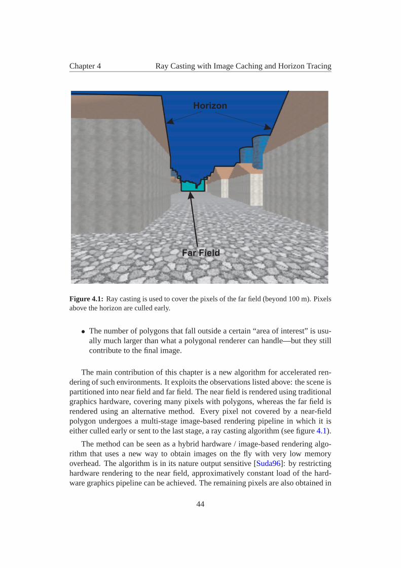
Chapter 4 Ray Casting with Image Caching and Horizon Tracing
Horizon
Far Field
Figure 4.1: Ray casting is used to cover the pixels of the far field (beyond 100 m). Pixelsabove the horizon are culled early.
• The number of polygons that fall outside a certain “area of interest” is usu-ally much larger than what a polygonal renderer can handle—but they stillcontribute to the final image.
The main contribution of this chapter is a new algorithm for accelerated ren-dering of such environments. It exploits the observations listed above: the scene ispartitioned into near field and far field. The near field is rendered using traditionalgraphics hardware, covering many pixels with polygons, whereas the far field isrendered using an alternative method. Every pixel not covered by a near-fieldpolygon undergoes a multi-stage image-based rendering pipeline in which it iseither culled early or sent to the last stage, a ray casting algorithm (see figure 4.1).
The method can be seen as a hybrid hardware / image-based rendering algo-rithm that uses a new way to obtain images on the fly with very low memoryoverhead. The algorithm is in its nature output sensitive [Suda96]: by restrictinghardware rendering to the near field, approximatively constant load of the hard-ware graphics pipeline can be achieved. The remaining pixels are also obtained in
44
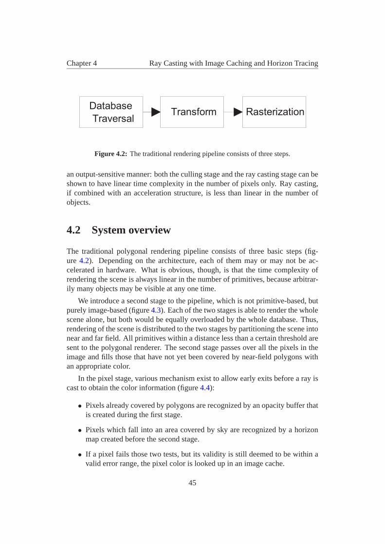
Chapter 4 Ray Casting with Image Caching and Horizon Tracing
Database
TraversalTransform Rasterization
Figure 4.2: The traditional rendering pipeline consists of three steps.
an output-sensitive manner: both the culling stage and the ray casting stage can beshown to have linear time complexity in the number of pixels only. Ray casting,if combined with an acceleration structure, is less than linear in the number ofobjects.
4.2 System overview
The traditional polygonal rendering pipeline consists of three basic steps (fig-ure 4.2). Depending on the architecture, each of them may or may not be ac-celerated in hardware. What is obvious, though, is that the time complexity ofrendering the scene is always linear in the number of primitives, because arbitrar-ily many objects may be visible at any one time.
We introduce a second stage to the pipeline, which is not primitive-based, butpurely image-based (figure 4.3). Each of the two stages is able to render the wholescene alone, but both would be equally overloaded by the whole database. Thus,rendering of the scene is distributed to the two stages by partitioning the scene intonear and far field. All primitives within a distance less than a certain threshold aresent to the polygonal renderer. The second stage passes over all the pixels in theimage and fills those that have not yet been covered by near-field polygons withan appropriate color.
In the pixel stage, various mechanism exist to allow early exits before a ray iscast to obtain the color information (figure 4.4):
• Pixels already covered by polygons are recognized by an opacity buffer thatis created during the first stage.
• Pixels which fall into an area covered by sky are recognized by a horizonmap created before the second stage.
• If a pixel fails those two tests, but its validity is still deemed to be within avalid error range, the pixel color is looked up in an image cache.
45
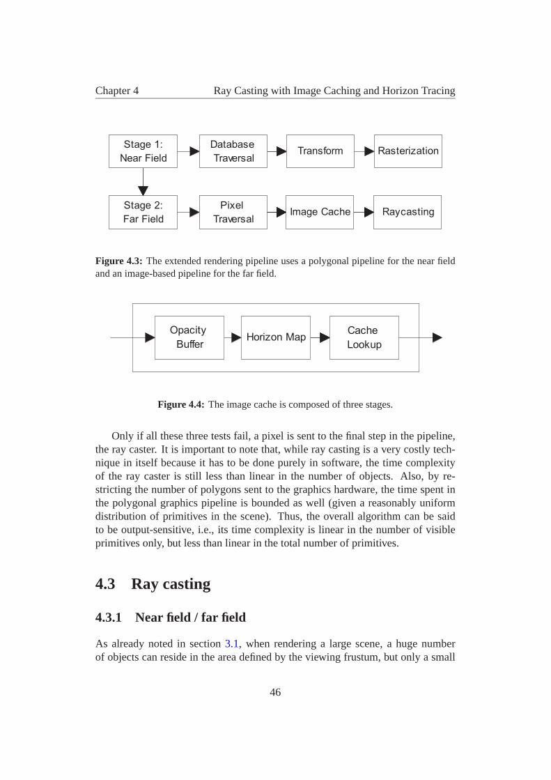
Chapter 4 Ray Casting with Image Caching and Horizon Tracing
Database
TraversalTransform Rasterization
Pixel
TraversalImage Cache Raycasting
Stage 1:
Near Field
Stage 2:
Far Field
Figure 4.3: The extended rendering pipeline uses a polygonal pipeline for the near fieldand an image-based pipeline for the far field.
Horizon MapCache
Lookup
Opacity
Buffer
Figure 4.4: The image cache is composed of three stages.
Only if all these three tests fail, a pixel is sent to the final step in the pipeline,the ray caster. It is important to note that, while ray casting is a very costly tech-nique in itself because it has to be done purely in software, the time complexityof the ray caster is still less than linear in the number of objects. Also, by re-stricting the number of polygons sent to the graphics hardware, the time spent inthe polygonal graphics pipeline is bounded as well (given a reasonably uniformdistribution of primitives in the scene). Thus, the overall algorithm can be saidto be output-sensitive, i.e., its time complexity is linear in the number of visibleprimitives only, but less than linear in the total number of primitives.
4.3 Ray casting
4.3.1 Near field / far field
As already noted in section 3.1, when rendering a large scene, a huge numberof objects can reside in the area defined by the viewing frustum, but only a small
46
Chapter 4 Ray Casting with Image Caching and Horizon Tracing
amount of those objects actually contribute to the appearance of the image. Large,near objects usually have much more impact on appearance than small and faraway objects.
It should therefore be possible to determine a set of objects that have the mostcontribution to the image, and only render this set of objects. The simplest wayto achieve this is to select all objects within a maximum distance of the viewer.We define the near field to be the space where these particular objects reside. Thisapproach is very popular, especially in computer games, and it is often combinedwith fogging, so that the transition between the near field and the space whereobjects are simply not rendered is not so sudden.
Obviously, culling away all objects that do not belong to the near field intro-duces severe visual artifacts. The far field contains objects beyond the near field,but not so far away as to be totally indiscernible. An important property of the farfield is that it usually
• consists of much more polygons than the graphics hardware can render, but
• contributes to only very few pixels on the screen, because most of the pixelshave already been covered by near field polygons.
To take advantage of this fact, a separate memory buffer, the opacity buffer, isused. For every frame, it records which pixels have already been covered by thenear field.
The basic algorithm for our image-based rendering technique using ray castingis as follows:
1. Find objects in the near field using a regular grid.
2. Render those objects with graphics hardware.
3. Rasterize them into the opacity buffer.
4. Go through the opacity buffer and cast a ray for each uncovered pixel (enterthe resulting color in a separate buffer).
5. Copy the pixels gained by ray casting to the frame buffer.
47
Chapter 4 Ray Casting with Image Caching and Horizon Tracing
4.3.2 Ray casting
We claim that ray casting is an appropriate technique for acquiring images forimage-based rendering on the fly. This might seem strange at first glance, becauseray casting (ray tracing) is known to be a notoriously slow technique. The rea-son for that is its high complexity: in a naıve approach, every object has to beintersected with a ray for every pixel, so the complexity is O(pn) as discussed insection 2.5.2. In our approach, we cast only primary rays into the scene throughindividual pixels and find the first hit, i.e., the first intersection with an object inthe far field. No secondary rays have to be cast, and we are interested in so-calledfirst-hit acceleration techniques.
From the first days of ray tracing, acceleration structures have been used to re-duce the number of ray-object intersection tests for individual rays. As discussedin section 2.5.1, the two most popular are bounding volume hierarchies and hier-archical space subdivision. Of all the methods proposed, the regular grid approachis the most interesting for our purpose: space is partitioned uniformly into a gridstructure, and all objects are entered into the grid cells with which they intersect.
It has been shown (see section 2.5.2) that theoretically, using an appropriateacceleration structure, the time complexity of ray tracing can be reduced to O(1),i.e., constant, in the number of objects (although this constant may be very large).In our experiments we have observed a sublinear rise in the time to cast rays intoa very large scene.
The advantage of the regular grids is their speed. Also, given a more or lessuniform distribution of objects—which we can safely assume for many types ofvirtual environments—the memory overhead is very low. Tracing through a gridis fast, using for example Woo’s incremental algorithm [Aman87] which onlyrequires few floating point operations per grid cell. If more objects are added,runtime behavior can even improve because rays will collide earlier with objectsthan if there were huge empty spaces in the grid.
The regular grid also provides a simple solution to view-frustum culling, whichis necessary to quickly find the objects that have to be rendered in the near field.
Note that since ray casting and hardware rendering provide color values forthe same image, care has to be taken to implement the same lighting and shadingmodel for both. The color values produced in the frame buffer by an OpenGLsystem, for example, are well specified and can easily be simulated in the shadingmodule of the ray caster, so that the distinction between near and far field is notvisible on screen.
For certain scenes, ray casting alone might already be sufficient and moder-ate gains can be observed. But generally, this still leaves too many pixels for
48
Chapter 4 Ray Casting with Image Caching and Horizon Tracing
which rays have to be cast, and while the time required for ray casting is relativelyindependent of scene complexity, casting a single ray is expensive compared topolygonal rendering and thus only tractable for a moderate number of pixels. Thefollowing sections explain how image caching and horizon tracing can be used todrastically reduce the number of rays that have to be cast.
4.4 Image caching
4.4.1 Panoramic image cache
Usually, walkthrough sequences exhibit a considerable amount of temporal coher-ence: the viewpoint changes only by a small amount between successive frames.We exploit this coherence in our system: instead of tracing every far-field pixelevery frame, we retain all the color values of the previous frame and try to retraceonly those pixels that are outdated according to some error metrics.
The validity of pixels depends strongly on the type of viewpoint motion:
Forward/Backward motion: This makes up for a very large amount of motionsin a walkthrough sequence. The farther away an object is, the smaller is theamount of pixels it moves on the screen due to forward/backward motion.Many pixels will even remain at the same location, so just reusing the pixelsfrom the previous frame is already a good first approximation.
Head Rotation: Rotation is quite different from forward/backward motion: reus-ing the contents of the frame buffer would indeed be a very bad solution,because all pixels would be wrong. But actually, many pixels are still valid,they have just moved to a different position. So what is needed is a methodto store traced pixels that does not depend on the orientation of the viewer.
Panning (left/right, up/down): This type of movement is similar to rotation inthat most pixels move to a different place.
Our assumption is that forward/backward motion and rotation will be the ma-jor types of motion in a walkthrough sequence. We therefore choose a represen-tation which is independent of viewpoint rotation: a panoramic image cache.
Panoramic images have been demonstrated to be a very efficient tool to storefull views of a scene where rotation is allowed. We use the panoramic image cachenot for presenting a precomputed panorama as for example in the Quicktime VRsystem [Chen95], but we use it as a rotation-independent image cache.
49
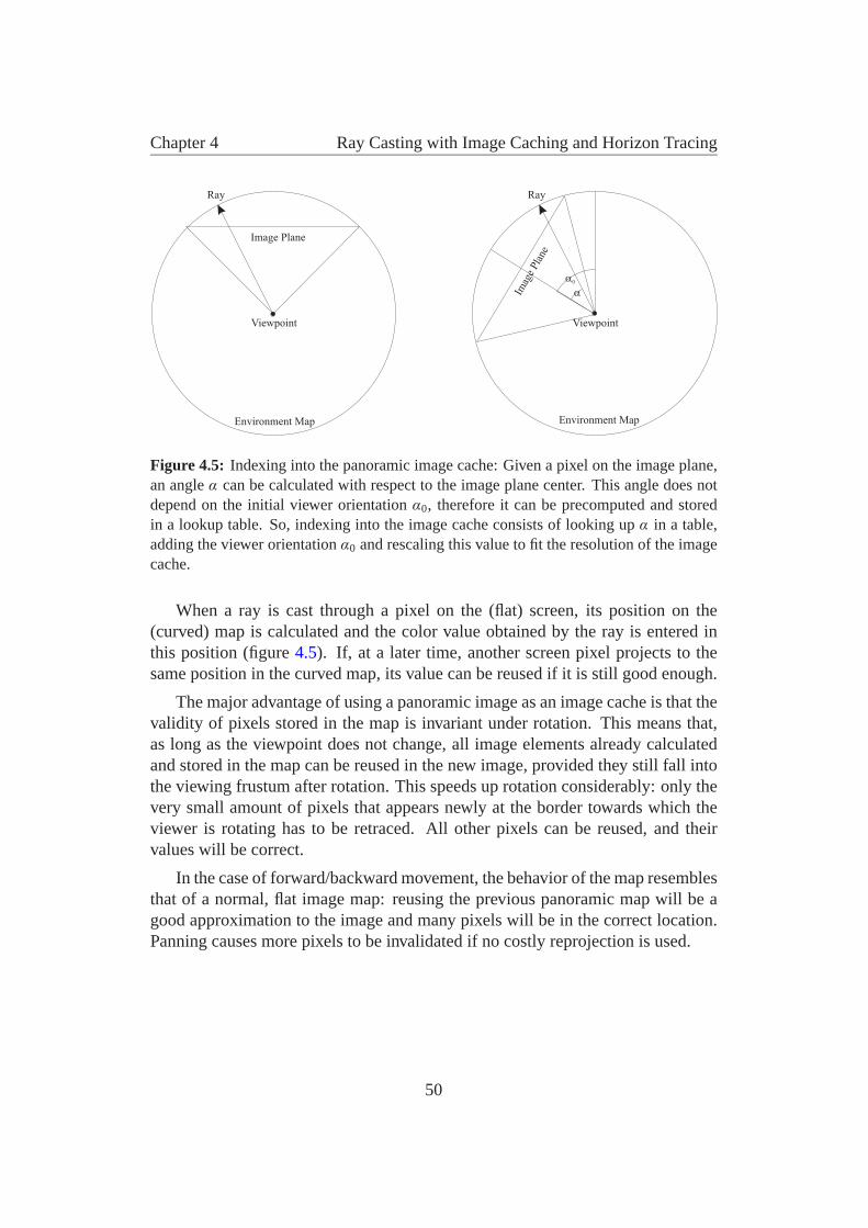
Chapter 4 Ray Casting with Image Caching and Horizon Tracing
Viewpoint
Ray Ray
Viewpoint
Image Plane
Imag
ePla
ne
Environment Map Environment Map
��
�
Figure 4.5: Indexing into the panoramic image cache: Given a pixel on the image plane,an angle α can be calculated with respect to the image plane center. This angle does notdepend on the initial viewer orientation α0, therefore it can be precomputed and storedin a lookup table. So, indexing into the image cache consists of looking up α in a table,adding the viewer orientation α0 and rescaling this value to fit the resolution of the imagecache.
When a ray is cast through a pixel on the (flat) screen, its position on the(curved) map is calculated and the color value obtained by the ray is entered inthis position (figure 4.5). If, at a later time, another screen pixel projects to thesame position in the curved map, its value can be reused if it is still good enough.
The major advantage of using a panoramic image as an image cache is that thevalidity of pixels stored in the map is invariant under rotation. This means that,as long as the viewpoint does not change, all image elements already calculatedand stored in the map can be reused in the new image, provided they still fall intothe viewing frustum after rotation. This speeds up rotation considerably: only thevery small amount of pixels that appears newly at the border towards which theviewer is rotating has to be retraced. All other pixels can be reused, and theirvalues will be correct.
In the case of forward/backward movement, the behavior of the map resemblesthat of a normal, flat image map: reusing the previous panoramic map will be agood approximation to the image and many pixels will be in the correct location.Panning causes more pixels to be invalidated if no costly reprojection is used.
50

Chapter 4 Ray Casting with Image Caching and Horizon Tracing
4.4.2 Cache update strategy
Assuming that pixels which have been traced in a previous frame are retained inan image cache, the algorithm has to decide which pixels are considered goodenough according to a certain error metric, and which pixels have to be retraced.In an interactive walkthrough system, the decision can also be based on a givenpixel-budget instead of an error metric: which pixels are the most important onesto retrace, given a maximum amount of pixels available per frame.
As with any speedup-algorithm, worst-case scenarios can be constructed thatdo not benefit from the algorithm. In such a case, our approach allows progressiverefinement by iteratively retracing all necessary pixels every frame. As soon asthe scenery gets more suited to the algorithm or the observer does not move for ashort moment, the system is able to catch up again.
To select an appropriate set of pixels to retrace, we assign a confidence valueto each pixel in the map. The pixels are then ordered according to their confidencevalues and tracing starts with the pixels that have the lowest confidence, proceed-ing to better ones until the pixel budget is exhausted. Finding a good heuristicfor the confidence value of a pixel is not trivial. We have chosen the followingapproach:
Every frame in which the observer moves more than a certain distance (rota-tion is not taken into account, as the image cache is rotation-independent), a newconfidence record is created, which contains the current observer position (fig-ure 4.6). All pixels which are traced during this particular frame are assigned apointer to the current confidence record (pixels which have not been traced at allpoint to a “lowest-confidence” record).
After a few frames, there will be a certain amount of confidence records (asmany as there were distinct observer positions), and each pixel in the image cachewill reference exactly one of those records. This information is used as follows:
During the polygonal rendering stage, a new opacity buffer is created. Allpixels of this buffer are visited sequentially. If a pixel is covered by a polygon, itis ignored. If not, a lookup is done into the image cache to find out the confidencerecord associated with this pixel. The confidence record also contains a pixelcounter which is then incremented.
After all pixels have been visited, each confidence record contains the numberof pixels that refer to it in its internal counter. Now, the observer position stored ineach confidence record can be compared to the current observer position and thedistance between the two is remembered as the current confidence value of thisconfidence record. All confidence records are sorted according to this confidencevalue.
51
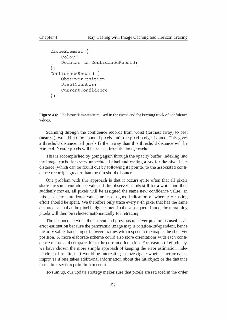
Chapter 4 Ray Casting with Image Caching and Horizon Tracing
CacheElement {Color;Pointer to ConfidenceRecord;
};ConfidenceRecord {
ObserverPosition;PixelCounter;CurrentConfidence;
};
Figure 4.6: The basic data-structure used in the cache and for keeping track of confidencevalues.
Scanning through the confidence records from worst (farthest away) to best(nearest), we add up the counted pixels until the pixel budget is met. This givesa threshold distance: all pixels farther away than this threshold distance will beretraced. Nearer pixels will be reused from the image cache.
This is accomplished by going again through the opacity buffer, indexing intothe image cache for every unoccluded pixel and casting a ray for the pixel if itsdistance (which can be found out by following its pointer to the associated confi-dence record) is greater than the threshold distance.
One problem with this approach is that it occurs quite often that all pixelsshare the same confidence value: if the observer stands still for a while and thensuddenly moves, all pixels will be assigned the same new confidence value. Inthis case, the confidence values are not a good indication of where ray castingeffort should be spent. We therefore only trace every n-th pixel that has the samedistance, such that the pixel budget is met. In the subsequent frame, the remainingpixels will then be selected automatically for retracing.
The distance between the current and previous observer position is used as anerror estimation because the panoramic image map is rotation-independent, hencethe only value that changes between frames with respect to the map is the observerposition. A more elaborate scheme could also store orientations with each confi-dence record and compare this to the current orientation. For reasons of efficiency,we have chosen the more simple approach of keeping the error estimation inde-pendent of rotation. It would be interesting to investigate whether performanceimproves if one takes additional information about the hit object or the distanceto the intersection point into account.
To sum up, our update strategy makes sure that pixels are retraced in the order
52
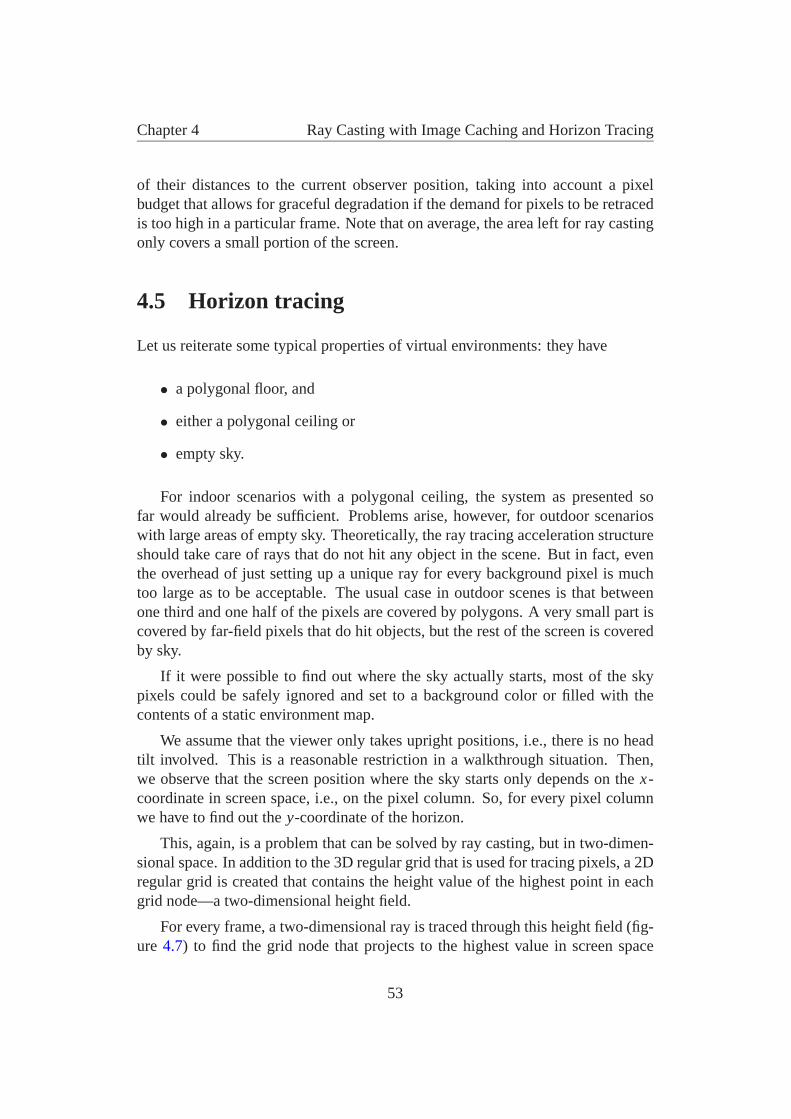
Chapter 4 Ray Casting with Image Caching and Horizon Tracing
of their distances to the current observer position, taking into account a pixelbudget that allows for graceful degradation if the demand for pixels to be retracedis too high in a particular frame. Note that on average, the area left for ray castingonly covers a small portion of the screen.
4.5 Horizon tracing
Let us reiterate some typical properties of virtual environments: they have
• a polygonal floor, and
• either a polygonal ceiling or
• empty sky.
For indoor scenarios with a polygonal ceiling, the system as presented sofar would already be sufficient. Problems arise, however, for outdoor scenarioswith large areas of empty sky. Theoretically, the ray tracing acceleration structureshould take care of rays that do not hit any object in the scene. But in fact, eventhe overhead of just setting up a unique ray for every background pixel is muchtoo large as to be acceptable. The usual case in outdoor scenes is that betweenone third and one half of the pixels are covered by polygons. A very small part iscovered by far-field pixels that do hit objects, but the rest of the screen is coveredby sky.
If it were possible to find out where the sky actually starts, most of the skypixels could be safely ignored and set to a background color or filled with thecontents of a static environment map.
We assume that the viewer only takes upright positions, i.e., there is no headtilt involved. This is a reasonable restriction in a walkthrough situation. Then,we observe that the screen position where the sky starts only depends on the x-coordinate in screen space, i.e., on the pixel column. So, for every pixel columnwe have to find out the y-coordinate of the horizon.
This, again, is a problem that can be solved by ray casting, but in two-dimen-sional space. In addition to the 3D regular grid that is used for tracing pixels, a 2Dregular grid is created that contains the height value of the highest point in eachgrid node—a two-dimensional height field.
For every frame, a two-dimensional ray is traced through this height field (fig-ure 4.7) to find the grid node that projects to the highest value in screen space
53
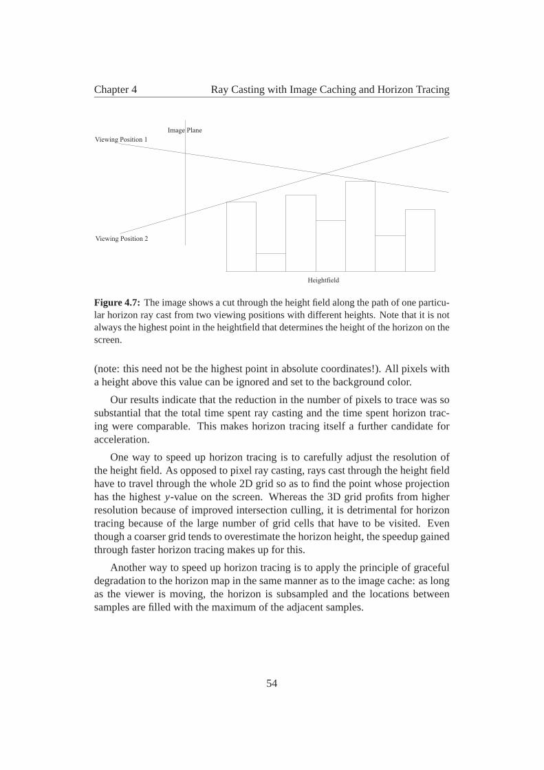
Chapter 4 Ray Casting with Image Caching and Horizon Tracing
Image Plane
Viewing Position 1
Viewing Position 2
Heightfield
Figure 4.7: The image shows a cut through the height field along the path of one particu-lar horizon ray cast from two viewing positions with different heights. Note that it is notalways the highest point in the heightfield that determines the height of the horizon on thescreen.
(note: this need not be the highest point in absolute coordinates!). All pixels witha height above this value can be ignored and set to the background color.
Our results indicate that the reduction in the number of pixels to trace was sosubstantial that the total time spent ray casting and the time spent horizon trac-ing were comparable. This makes horizon tracing itself a further candidate foracceleration.
One way to speed up horizon tracing is to carefully adjust the resolution ofthe height field. As opposed to pixel ray casting, rays cast through the height fieldhave to travel through the whole 2D grid so as to find the point whose projectionhas the highest y-value on the screen. Whereas the 3D grid profits from higherresolution because of improved intersection culling, it is detrimental for horizontracing because of the large number of grid cells that have to be visited. Eventhough a coarser grid tends to overestimate the horizon height, the speedup gainedthrough faster horizon tracing makes up for this.
Another way to speed up horizon tracing is to apply the principle of gracefuldegradation to the horizon map in the same manner as to the image cache: as longas the viewer is moving, the horizon is subsampled and the locations betweensamples are filled with the maximum of the adjacent samples.
54
Chapter 4 Ray Casting with Image Caching and Horizon Tracing
0
100
200
300
400
500
600
700
800
900
1
15
29
43
57
71
85
99
11
3
12
7
14
1
15
5
16
9
18
3
19
7
21
1
22
5
23
9
25
3
26
7
28
1
29
5
30
9
32
3
33
7
35
1
36
5
37
9
39
3
40
7
42
1
frames
tim
e(m
s)
Hardware Full
Output Sensitive Algorithm
Hardware Near Field
Figure 4.8: The chart compares full hardware rendering (far plane set to infinity), ournew output sensitive algorithm, and hardware rendering (far field not rendered) with thefar plane at 100 m. The image resolution was 640x480 pixels for all tests. The averageframe rates were 2.0 fps for full hardware rendering and 9.25 fps for the new algorithm,so the speedup is about 4.6.
4.6 Results
The algorithms described in this chapter have been implemented and tested in anapplication environment for creating professional computer games. The systemwas tested with a Pentium 233MMX processor, which was moderately fast for aconsumer PC at the time when the tests were conducted. The 3D board used was a3DFX Voodoo Graphics, one of the first PC graphics boards providing significantpixel fill rate. Both CPU and graphics power have increased about tenfold sincethe implementation of these tests, so the results shown here are still a good esti-mate of the speedup that is possible on current systems. The implementation isquite crude, and performance gains are likely to be achieved by careful optimiza-tion of critical per-pixel operations. New SIMD instructions available in currentCPUs give further room for optimization.
One problem to be solved is how to create an occlusion map, and how toreuse it for rendering. Surprisingly, graphics hardware is not of much help in thiscase: transfers from frame-buffer memory to main memory are usually very slow,except theoretically in some specialized architectures which incorporate a unifiedmemory concept (e.g., the Silicon Graphics O2 [Kilg97]).
Therefore, while the near field is rendered in the frame buffer using graphicshardware, we create a 1-bit opacity buffer with a very fast software renderer, tak-ing advantage of the fact that neither shading nor depth information is requiredfor the opacity buffer. Our current implementation is limited to upright view-
55
Chapter 4 Ray Casting with Image Caching and Horizon Tracing
ing positions only. This restriction is inherent to the horizon tracing acceleration,and we believe that it does not severely infringe on the freedom of movement in awalkthrough environment. With respect to the image cache, a spherical map couldeasily be used instead of the cylindrical map that we chose to implement, allowingthe viewer to also look up and down.
Although our ray caster can simulate the color values produced by hardwarerendering exactly, we observed that typical far-field triangles do not cover morethan one or two pixels. As we are also using a prelit model, we decided to store foreach triangle a precalculated color value with lighting and texture (on the lowestmip-map level) already applied. This avoids having to find the exact intersectionpoint and evaluating the lighting model for each triangle intersection. We did notnotice a significant degradation in image quality due to this optimization.
The first graph (figure 4.8) shows the time taken to render each frame of arecorded walkthrough sequence (about 400 frames) through a moderately largeenvironment, a city containing approximately 150,000 triangles. Two of the se-ries are for pure hardware rendering only, with the far plane set to infinity in onecase and 100 meters in the other case. The far field is not rendered at all, andour algorithm disabled completely (so there is no overhead for tracing horizonpixels, creating or going through the opacity buffer etc.). It shows that up to a cer-tain distance, graphics hardware can render the scene very quickly, but of coursemisses out on a considerable amount of the background. But if the whole sceneis rendered indiscriminately, the hardware simply cannot cope with the amount oftriangles, and the frame rate drops to an unacceptably low value.
Obviously, these are the two extremes between which our algorithm can orshould operate. It will certainly not get faster than just rendering the near field,but it should be considerably faster than rendering the whole scene with trianglesonly. The third series shows how the algorithm performs for the same walkthroughsequence with the far plane set at 100 meters—ray casting, image caching andhorizon tracing enabled. A speedup of up to one order of magnitude over render-ing the full scene in hardware can be observed.
To give a feeling for the operating behavior of the algorithm, the second graph(figure 4.9) shows frame times for our algorithm with different near-field sizes(i.e., the far plane set to different values). Increasing the far-plane distance beyonda certain limit reduces performance, because more triangles have to be rendered,but they do not further reduce the number of pixels that have to be traced. Settingthe far plane too near gives a very non-uniform frame rate.
The third graph (figure 4.10) gives an impression of what the algorithm iscapable of if the screen resolution is reduced and the scenery is more complex(in this walkthrough sequence, almost all of the polygons were in the viewing
56
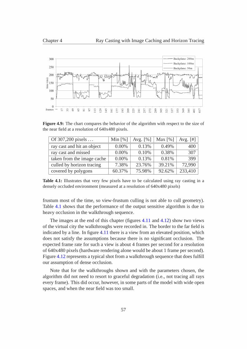
Chapter 4 Ray Casting with Image Caching and Horizon Tracing
0
50
100
150
200
250
3001
17
33
49
65
81
97
11
3
12
9
14
5
16
1
17
7
19
3
20
9
22
5
24
1
25
7
27
3
28
9
30
5
32
1
33
7
35
3
36
9
38
5
40
1
41
7frames
tim
e(m
s)
Backplane: 200m
Backplane: 100m
Backplane: 50m
Figure 4.9: The chart compares the behavior of the algorithm with respect to the size ofthe near field at a resolution of 640x480 pixels.
Of 307,200 pixels . . . Min [%] Avg. [%] Max [%] Avg. [#]
ray cast and hit an object 0.00% 0.13% 0.49% 400ray cast and missed 0.00% 0.10% 0.38% 307taken from the image cache 0.00% 0.13% 0.81% 399culled by horizon tracing 7.38% 23.76% 39.21% 72,990covered by polygons 60.37% 75.98% 92.62% 233,410
Table 4.1: Illustrates that very few pixels have to be calculated using ray casting in adensely occluded environment (measured at a resolution of 640x480 pixels)
frustum most of the time, so view-frustum culling is not able to cull geometry).Table 4.1 shows that the performance of the output sensitive algorithm is due toheavy occlusion in the walkthrough sequence.
The images at the end of this chapter (figures 4.11 and 4.12) show two viewsof the virtual city the walkthroughs were recorded in. The border to the far field isindicated by a line. In figure 4.11 there is a view from an elevated position, whichdoes not satisfy the assumptions because there is no significant occlusion. Theexpected frame rate for such a view is about 4 frames per second for a resolutionof 640x480 pixels (hardware rendering alone would be about 1 frame per second).Figure 4.12 represents a typical shot from a walkthrough sequence that does fulfillour assumption of dense occlusion.
Note that for the walkthroughs shown and with the parameters chosen, thealgorithm did not need to resort to graceful degradation (i.e., not tracing all raysevery frame). This did occur, however, in some parts of the model with wide openspaces, and when the near field was too small.
57
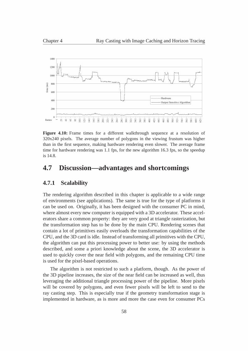
Chapter 4 Ray Casting with Image Caching and Horizon Tracing
0
200
400
600
800
1000
1200
14001
21
41
61
81
10
1
12
1
14
1
16
1
18
1
20
1
22
1
24
1
26
1
28
1
30
1
32
1
34
1
36
1
38
1
40
1
42
1
44
1
46
1
48
1
50
1
52
1
54
1
56
1
58
1
60
1
62
1frames
tim
e(m
s)
Hardware
Output Sensitive Algorithm
Figure 4.10: Frame times for a different walkthrough sequence at a resolution of320x240 pixels. The average number of polygons in the viewing frustum was higherthan in the first sequence, making hardware rendering even slower. The average frametime for hardware rendering was 1.1 fps, for the new algorithm 16.3 fps, so the speedupis 14.8.
4.7 Discussion—advantages and shortcomings
4.7.1 Scalability
The rendering algorithm described in this chapter is applicable to a wide rangeof environments (see applications). The same is true for the type of platforms itcan be used on. Originally, it has been designed with the consumer PC in mind,where almost every new computer is equipped with a 3D accelerator. These accel-erators share a common property: they are very good at triangle rasterization, butthe transformation step has to be done by the main CPU. Rendering scenes thatcontain a lot of primitives easily overloads the transformation capabilities of theCPU, and the 3D card is idle. Instead of transforming all primitives with the CPU,the algorithm can put this processing power to better use: by using the methodsdescribed, and some a priori knowledge about the scene, the 3D accelerator isused to quickly cover the near field with polygons, and the remaining CPU timeis used for the pixel-based operations.
The algorithm is not restricted to such a platform, though. As the power ofthe 3D pipeline increases, the size of the near field can be increased as well, thusleveraging the additional triangle processing power of the pipeline. More pixelswill be covered by polygons, and even fewer pixels will be left to send to theray casting step. This is especially true if the geometry transformation stage isimplemented in hardware, as is more and more the case even for consumer PCs
58
Chapter 4 Ray Casting with Image Caching and Horizon Tracing
and 3D workstations.
But even if a high-end graphics pipeline exists, the ideas of this paper arevalid: there will always be scenes too large and too complex to handle even withthe best graphics hardware. Adjusting the size of the near field to the speed of thepolygon pipeline provides a good parameter for tuning an application for speedon a specific platform.
This means that the approach scales very well with CPU processing power aswell as with graphics pipeline speed, and the result is an output-sensitive algorithmthat can be used in many different setups.
4.7.2 Aliasing
No speedup comes without a cost. There are two reasons why aliasing occurs inthe algorithm: first, ray casting itself is a source of aliasing because the scene ispoint sampled with rays (the same is true for hardware geometry rendering, by theway). The other reason is aliasing due to the projection of the flat screen into acurved image map and back.
In both cases, antialiasing would theoretically be possible, but it would have aheavy impact on the performance of the algorithm, thus defying its purpose, i.e.to accelerate interactive walkthroughs. In chapter 5, we will present a method toremedy aliasing effects. In contrast to the online method presented here, however,this method will require a significant amount of preprocessing.
4.8 Applications
There is a variety of applications where the algorithms presented in this chaptercould be applied. Foremost, there is:
4.8.1 Walkthroughs
Many types of virtual environment walkthroughs fulfill the basic preconditions thealgorithm requires. First and foremost, urban environments are ideal to showcasethe points of this chapter. Especially in a city, most of the screen is covered by thebuildings that are near to the viewer. But there are also several viewpoints whereobjects are visible that are still very far away—imagine looking down a very longstreet. Polygons cover the right, left and lower part of the image, a good partof the sky is caught by horizon tracing, and the remaining part can be efficiently
59
Chapter 4 Ray Casting with Image Caching and Horizon Tracing
found by ray casting. Note that under normal circumstances, such scenes areeither excruciatingly slow to render, or the far-plane distance is simply set so nearthat the result does not look very convincing.
Any other scenery that is densely occluded is also suitable. For example, walk-ing through virtual woods is very difficult to do with graphics hardware alone—but with our algorithm, a good number of trees could be rendered in the near field,and the remaining pixels traced.
4.8.2 Computer Games
In recent times, first person 3D computer games have gained immense popularity.Many of them are restricted to indoor environments, because portal renderingprovides a very good solution for the complexity problem in this case. But fewhave ventured to outdoor scenarios, and most of those who have rely on heavyfogging to reduce the amount of polygons to render. Sometimes the far planeis not set much farther than 10–20 meters, which does not provide for a veryrealistic feeling. Using the described algorithm, the perceived far plane can bepushed back to the horizon, or at least a considerable distance further away, as thespace between the previous far plane and the horizon can be covered by far-fieldrendering.
Neither graphics hardware nor processing power will be lacking for computergames in the near future, as both are rapidly catching up with workstation stan-dards. The benchmarks were done on a system whose performance is by no meansstate of the art even for a PC environment (see section 4.6), but they show thatgood results can be achieved nevertheless.
4.8.3 Portal Tracing
Previous work [Alia97] has suggested the use of textures as a cache for renderingportals in indoor environments. Those textures are calculated by using graphicshardware. We believe that it might be advantageous to use ray casting to tracethrough the portals: far away portals cover only a small amount of space on thescreen, so there are very few pixels to trace—but the amount of geometry behinda portal can still be quite large, especially if portals have to be traced recursively.Of course in this case, the horizon tracing stage can be omitted.
60
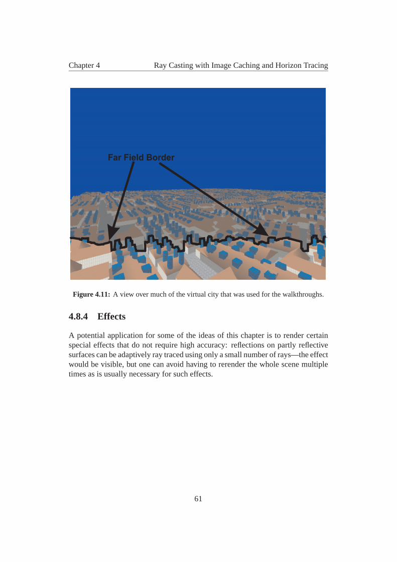
Chapter 4 Ray Casting with Image Caching and Horizon Tracing
Far Field Border
Figure 4.11: A view over much of the virtual city that was used for the walkthroughs.
4.8.4 Effects
A potential application for some of the ideas of this chapter is to render certainspecial effects that do not require high accuracy: reflections on partly reflectivesurfaces can be adaptively ray traced using only a small number of rays—the effectwould be visible, but one can avoid having to rerender the whole scene multipletimes as is usually necessary for such effects.
61
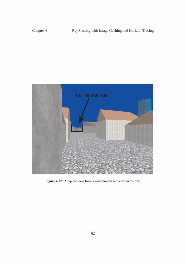
Chapter 4 Ray Casting with Image Caching and Horizon Tracing
Far Field Border
Figure 4.12: A typical view from a walkthrough sequence in the city.
62
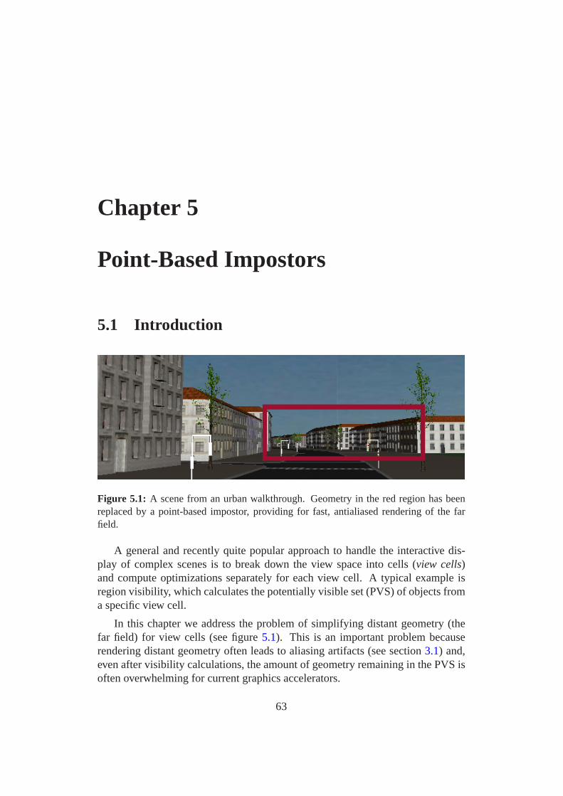
Chapter 5
Point-Based Impostors
5.1 Introduction
Figure 5.1: A scene from an urban walkthrough. Geometry in the red region has beenreplaced by a point-based impostor, providing for fast, antialiased rendering of the farfield.
A general and recently quite popular approach to handle the interactive dis-play of complex scenes is to break down the view space into cells (view cells)and compute optimizations separately for each view cell. A typical example isregion visibility, which calculates the potentially visible set (PVS) of objects froma specific view cell.
In this chapter we address the problem of simplifying distant geometry (thefar field) for view cells (see figure 5.1). This is an important problem becauserendering distant geometry often leads to aliasing artifacts (see section 3.1) and,even after visibility calculations, the amount of geometry remaining in the PVS isoften overwhelming for current graphics accelerators.
63
Chapter 5 Point-Based Impostors
We begin by defining our goals in this process. First, we set out to build a rep-resentation that provides a high-quality rendered image for all views from a spe-cific view cell. This means that we try to avoid artifacts such as holes, aliasing ormissing data, and that we require high fidelity in the rendering of view-dependentappearance changes. Second, we insist that our representation be as compactas possible, while being amenable to hardware acceleration on consumer-levelgraphics hardware.
Distant geometry has some peculiarities resulting from its complexity thatmake simplification difficult:
• One aspect is that because of limited image resolution and perspective pro-jection, typically several triangles project to a single pixel. This makes an-tialiasing and filtering an important issue.
• Another aspect is that we can not rely on surfaces to drive the simplificationprocess: the triangles that project to one pixel can stem from disconnectedsurfaces and even from different objects. This means, for example, thatthere is no well-defined normal for such a pixel.
Generally, simplification can be based either on geometric criteria as in mostlevel-of-detail approaches, or on image-based representations. Geometric simpli-fication is useful for certain models, but has its limitations. Scenes with alphatextures, regular structures as found in buildings, chaotic disconnected structuresas found in trees, or new shading paradigms such as pixel and vertex shading arenot easy to deal with even in recent appearance-based simplification methods. Wewill therefore concentrate on image-based simplification approaches.
We observe, however, that none of the simplified representations proposed todate meets all the goals defined above:
• Layered depth images (LDIs) and similar representations introduce bias inthe sampling patterns, and cannot accommodate situations in which manyprimitives project onto each pixel of a view. In the presence of such mi-crogeometry, we also have to be aware that appearance can change with theviewing direction. This requires a representation with directionally depen-dent information, such as a light field.
• Light field approaches are powerful enough to cope with complex and di-rectionally dependent appearance. However, geometric information needsto be incorporated into the light field in order to obtain acceptable qualitywithin a reasonable amount of storage space [Chai00]. A possible startingpoint to build an impostor would therefore be a surface lightfield [Wood00],
64
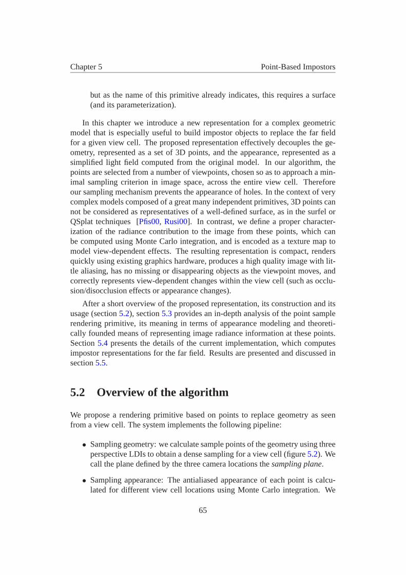
Chapter 5 Point-Based Impostors
but as the name of this primitive already indicates, this requires a surface(and its parameterization).
In this chapter we introduce a new representation for a complex geometricmodel that is especially useful to build impostor objects to replace the far fieldfor a given view cell. The proposed representation effectively decouples the ge-ometry, represented as a set of 3D points, and the appearance, represented as asimplified light field computed from the original model. In our algorithm, thepoints are selected from a number of viewpoints, chosen so as to approach a min-imal sampling criterion in image space, across the entire view cell. Thereforeour sampling mechanism prevents the appearance of holes. In the context of verycomplex models composed of a great many independent primitives, 3D points cannot be considered as representatives of a well-defined surface, as in the surfel orQSplat techniques [Pfis00, Rusi00]. In contrast, we define a proper character-ization of the radiance contribution to the image from these points, which canbe computed using Monte Carlo integration, and is encoded as a texture map tomodel view-dependent effects. The resulting representation is compact, rendersquickly using existing graphics hardware, produces a high quality image with lit-tle aliasing, has no missing or disappearing objects as the viewpoint moves, andcorrectly represents view-dependent changes within the view cell (such as occlu-sion/disocclusion effects or appearance changes).
After a short overview of the proposed representation, its construction and itsusage (section 5.2), section 5.3 provides an in-depth analysis of the point samplerendering primitive, its meaning in terms of appearance modeling and theoreti-cally founded means of representing image radiance information at these points.Section 5.4 presents the details of the current implementation, which computesimpostor representations for the far field. Results are presented and discussed insection 5.5.
5.2 Overview of the algorithm
We propose a rendering primitive based on points to replace geometry as seenfrom a view cell. The system implements the following pipeline:
• Sampling geometry: we calculate sample points of the geometry using threeperspective LDIs to obtain a dense sampling for a view cell (figure 5.2). Wecall the plane defined by the three camera locations the sampling plane.
• Sampling appearance: The antialiased appearance of each point is calcu-lated for different view cell locations using Monte Carlo integration. We
65
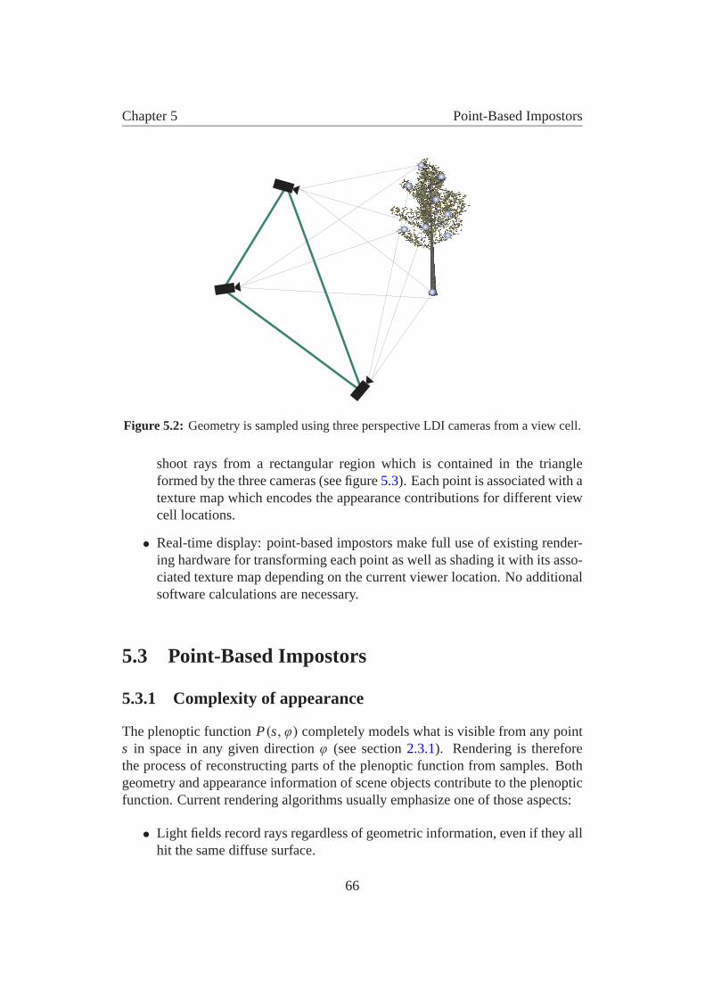
Chapter 5 Point-Based Impostors
Figure 5.2: Geometry is sampled using three perspective LDI cameras from a view cell.
shoot rays from a rectangular region which is contained in the triangleformed by the three cameras (see figure 5.3). Each point is associated with atexture map which encodes the appearance contributions for different viewcell locations.
• Real-time display: point-based impostors make full use of existing render-ing hardware for transforming each point as well as shading it with its asso-ciated texture map depending on the current viewer location. No additionalsoftware calculations are necessary.
5.3 Point-Based Impostors
5.3.1 Complexity of appearance
The plenoptic function P(s, ϕ) completely models what is visible from any points in space in any given direction ϕ (see section 2.3.1). Rendering is thereforethe process of reconstructing parts of the plenoptic function from samples. Bothgeometry and appearance information of scene objects contribute to the plenopticfunction. Current rendering algorithms usually emphasize one of those aspects:
• Light fields record rays regardless of geometric information, even if they allhit the same diffuse surface.
66
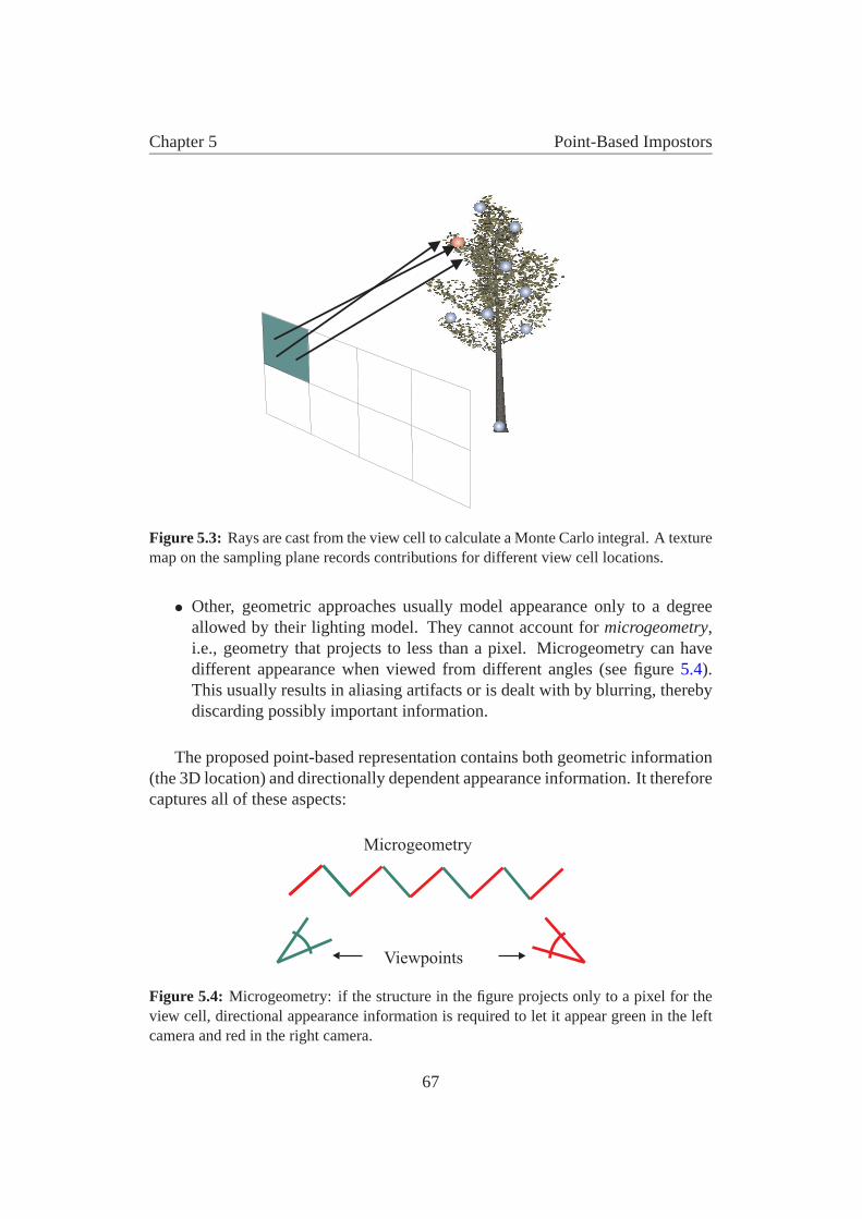
Chapter 5 Point-Based Impostors
Figure 5.3: Rays are cast from the view cell to calculate a Monte Carlo integral. A texturemap on the sampling plane records contributions for different view cell locations.
• Other, geometric approaches usually model appearance only to a degreeallowed by their lighting model. They cannot account for microgeometry,i.e., geometry that projects to less than a pixel. Microgeometry can havedifferent appearance when viewed from different angles (see figure 5.4).This usually results in aliasing artifacts or is dealt with by blurring, therebydiscarding possibly important information.
The proposed point-based representation contains both geometric information(the 3D location) and directionally dependent appearance information. It thereforecaptures all of these aspects:
Viewpoints
Microgeometry
Figure 5.4: Microgeometry: if the structure in the figure projects only to a pixel for theview cell, directional appearance information is required to let it appear green in the leftcamera and red in the right camera.
67
Chapter 5 Point-Based Impostors
• Point sampling can easily adapt to unstructured geometry in the absence ofsurfaces or a structured model.
• A point on a diffuse, locally flat surface which projects to more than a pixelhas the same appearance from all directions and can be encoded with asingle color.
• Objects with view-dependent lighting effects (e.g. specular lighting) showdifferent colors when viewed from different angles.
• Microgeometry is also view dependent and is encoded just like lighting ef-fects.
5.3.2 Geometric sampling
The first step in the creation of a point-based rendering primitive is to decideon the geometric location of the sample points. The points encode the part ofthe plenoptic function defined by the view cell and the geometry to be sampled.To allow hardware reconstruction, there should be no holes when projecting thepoints into any possible view from the view cell.
A sufficient criterion that a point-sampled surface will have no holes in a pro-jection is that the projected points can be triangulated so that the maximum pro-jected edgelength is smaller than the side length of a pixel [Gros98].
It is in general difficult to prove that a particular point-based representation ful-fills this criterion. For unit magnification and orthographic viewing, three orthog-onal LDIs provide such an adequate sampling [Lisc98]. Although this samplingstrategy works with our method, it is not well suited for far-field objects becausethe sampling density is not adapted to the possible viewing directions from theview cell and typically results in a large number of point samples. Therefore, ourmethod chooses perspective LDIs to better distribute the samples with respect tothe view cell.
The camera viewpoints are chosen so as to form a triangle which bounds theshaft formed by the view cell and the far-field object (see also figure 5.6). In thisway, the sampling rays from the three cameras most closely resemble the rayspossible from a viewpoint inside the view cell.
Note that three cameras are required in order to adequately sample arbitrarilyoriented surfaces. To see why this is necessary, assume for example that only theleft and right camera were used. In this case, any surface lying on a plane throughthe centers of projection of the two cameras would not be sampled at all (if the
68
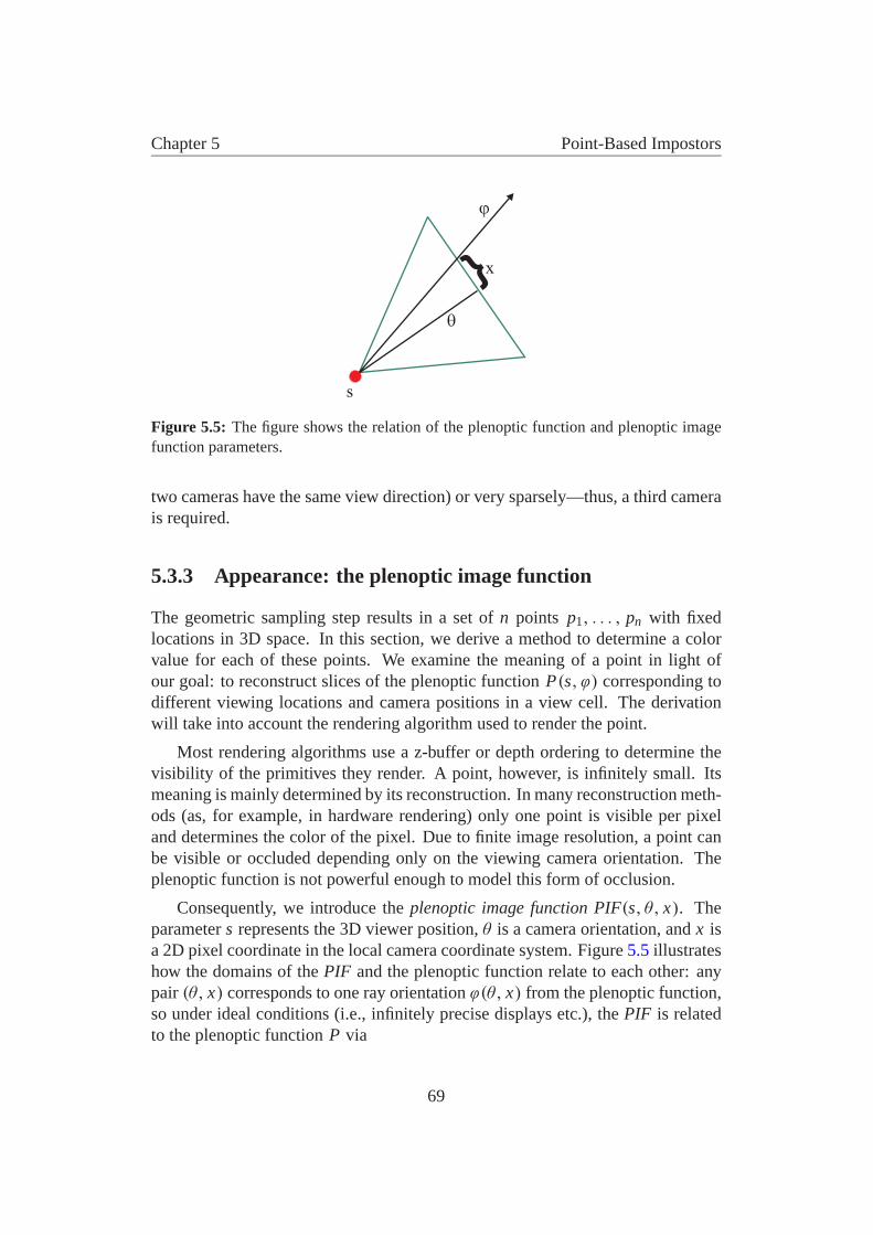
Chapter 5 Point-Based Impostors
�
�
s
x}
Figure 5.5: The figure shows the relation of the plenoptic function and plenoptic imagefunction parameters.
two cameras have the same view direction) or very sparsely—thus, a third camerais required.
5.3.3 Appearance: the plenoptic image function
The geometric sampling step results in a set of n points p1, . . . , pn with fixedlocations in 3D space. In this section, we derive a method to determine a colorvalue for each of these points. We examine the meaning of a point in light ofour goal: to reconstruct slices of the plenoptic function P(s, ϕ) corresponding todifferent viewing locations and camera positions in a view cell. The derivationwill take into account the rendering algorithm used to render the point.
Most rendering algorithms use a z-buffer or depth ordering to determine thevisibility of the primitives they render. A point, however, is infinitely small. Itsmeaning is mainly determined by its reconstruction. In many reconstruction meth-ods (as, for example, in hardware rendering) only one point is visible per pixeland determines the color of the pixel. Due to finite image resolution, a point canbe visible or occluded depending only on the viewing camera orientation. Theplenoptic function is not powerful enough to model this form of occlusion.
Consequently, we introduce the plenoptic image function PIF(s, θ, x). Theparameter s represents the 3D viewer position, θ is a camera orientation, and x isa 2D pixel coordinate in the local camera coordinate system. Figure 5.5 illustrateshow the domains of the PIF and the plenoptic function relate to each other: anypair (θ, x) corresponds to one ray orientation ϕ(θ, x) from the plenoptic function,so under ideal conditions (i.e., infinitely precise displays etc.), the PIF is relatedto the plenoptic function P via
69

Chapter 5 Point-Based Impostors
PIF(s, θ, x) = P(s, ϕ(θ, x))
Note that this mapping is many to one. The PIF with its additional parameterswill allow us to incorporate the visibility term inherent to current reconstructiontechniques directly into our calculations.
We now interpret points via the images they produce (their image functions)when rendered with a specific rendering algorithm—in our case, z-buffered hard-ware rendering.
If we consider only one point p j alone, the point defines an image functionr j (s, θ, x). This function specifies a continuous image for each set of cameraparameters (s, θ). Each of those images is set to the typical reconstruction filter ofa monitor, a Gaussian centered at the pixel which the point projects to. However,it is very crucial to see a point p j in relation to the other points in the point set. Wehave to take into account a visibility term v j which evaluates to 1 if the point p j isvisible in the image defined through the camera parameters (s, θ) and 0 otherwise.This gives us the actual image function Q j of a point:
Q j (s, θ, x) = v j (s, θ)r j (s, θ, x)
From an algebraic point of view, we can regard the functions Q j , 1 ≤ j ≤ n,as basis functions spanning a finite dimensional subspace 1 of the space of allPIFs. One element PIFfinite of this finite dimensional subspace can be written asa weighted sum of the basis functions of the points:
PIFfinite(s, θ, x) =∑
j
c j Q j (s, θ, x)
Note that the weight c j is the color value assigned to the point p j . The weightsc j should be chosen so as to make PIFfinite as close as possible to PIF. This can beachieved by minimizing ‖PIFfinite − PIF‖ (with respect to the Euclidean norm onthe space of functions over (s, θ, x)), and the resulting weights can then be foundvia the dual basis functions as
c j =∫∫∫
q j (s, θ, x)PIF(s, θ, x)ds dθ dx
where q j (s, θ, x) is the dual basis function (the dual basis functions are de-fined via 〈q j , Qk〉 = δ jk).
1The finite dimensional subspace describes all different images that can be produced by theparticular set of geometric samples (points) from the geometric sampling step.
70
Chapter 5 Point-Based Impostors
This representation only assigns one color value per point, regardless of thelocation s in the view cell. However, because of view-dependent shading effectsand micro-geometry as discussed in section 5.3.1, a point might need to showvery different appearance from different viewing locations. Thus, we make themodel more powerful by replacing the weights c j by functions c j (s). In order torepresent those functions, they are discretized with respect to the space of possibleviewing locations (this is similar in spirit to the camera aperture necessary whensampling light fields). Given a basis Bi (s) for this space, we can write each c j (s)in terms of this basis, with coefficients found via the dual basis bi (s):
c j (s) =∑
i
ci j Bi (s), where ci j =∫
c j (s)bi (s)ds
One possible choice for the basis Bi (s) is to use a regular subdivision of aplane with a normal directed from the view cell towards the objects. The weightsci j for each point p j can then be stored in a texture map. This means that c j (s)will be looked up in a texture map, which is typically reconstructed with a bilinearkernel, so Bi (s) is actually just a bilinear basis.
Putting all parts together, the rendering process is described with the formula
PIFfinite(s, θ, x) =∑i, j
ci j Q j (s, θ, x)Bi (s)
and the weights to make the PIFfinite resemble most closely the PIF are calcu-lated as
ci j =∫∫∫
PIF(s, θ, x)q j (s, θ, x)bi (s)ds dθ dx (5.1)
The final task is finding the dual basis functions. If our basis functions Q j Bi
were orthogonal, we would have q j = Q j and bi = Bi (apart from normalizationissues). In the non-orthogonal case, however, calculating the real duals is tedious:geometric occlusion means each one would be different; one would really haveto invert a large matrix for each one to find a (discretized) version of the dual.We have opted for an approximate approach inspired by signal theory: both thebilinear basis Bi and the monitor reconstruction filter r j can be regarded as an ap-proximation to the ideal (and orthogonal) reconstruction filter, a sinc-function. Asis common practice, we approximate the ideal lowpass filter (the signal-theoreticversion of dual basis functions) using Gaussians.
71
Chapter 5 Point-Based Impostors
The integral (5.1) can be estimated using Monte Carlo integration with bi andq j as importance functions. Samples PIF(s, θ, x) = P(s, ϕ(θ, x)) are calculatedwith a simple ray tracer.
5.4 Implementation
In this section we describe the choices made in our particular implementation ofthe method.
5.4.1 Obtaining geometric samples
Before placing the three LDI cameras used to obtain geometric samples, we choosea sampling plane to parameterize viewer positions within the view cell: as in lightfields, we use a plane with a normal oriented from the view cell towards the farfield. The supporting planes [Coor99] of view cell and far-field object bound-ing box form a shaft between the two. The supporting planes can be found forexample by iteratively creating planes between an edge of the view cell and a ver-tex of the far-field bounding box, and testing whether both the view cell and thebounding box lie on the same side of the plane (and vice versa with an edge of thebounding box and a vertex of the view cell).
Then, we calculate the intersection of the shaft with the sampling plane. Theresulting polygon on the sampling plane can be tightly bounded with a triangle(we use the triangle with the top edge parallel to the ground and minimum cir-cumference). The three LDI cameras are now placed at the corners of this triangle(see figure 5.6). Note that camera placement is generally well behaved, as longas the view cell does not intersect the far-field bounding box (which should neveroccur).
In order to determine the LDI resolution necessary to avoid holes in the re-projection of the sampled points, our method offers a sampling mechanism basedon a 2D observation: Suppose we have two cameras on both ends of a segmentof possible viewing locations in 2D, and a short edge viewed by the two cameras.These two cameras are used to sample the endpoints of the edge. Resampling hap-pens from a camera placed anywhere on the segment between the two cameras.It can now be shown that the “worst” discrepancy between the resampling angleα and the sampling angle β appears if the edge is parallel to the segment joiningthe two cameras, and if the center of the edge is equidistant to both cameras (seefigure 5.7).
72
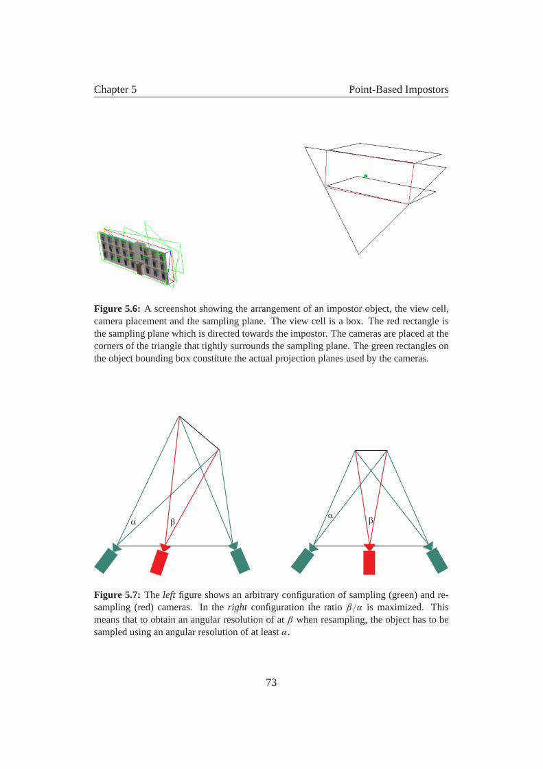
Chapter 5 Point-Based Impostors
Figure 5.6: A screenshot showing the arrangement of an impostor object, the view cell,camera placement and the sampling plane. The view cell is a box. The red rectangle isthe sampling plane which is directed towards the impostor. The cameras are placed at thecorners of the triangle that tightly surrounds the sampling plane. The green rectangles onthe object bounding box constitute the actual projection planes used by the cameras.
� ��
�
Figure 5.7: The left figure shows an arbitrary configuration of sampling (green) and re-sampling (red) cameras. In the right configuration the ratio β/α is maximized. Thismeans that to obtain an angular resolution of at β when resampling, the object has to besampled using an angular resolution of at least α.
73
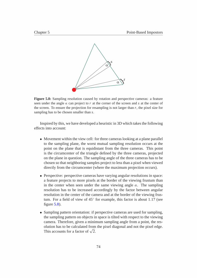
Chapter 5 Point-Based Impostors
s}
� }
�
r
Figure 5.8: Sampling resolution caused by rotation and perspective cameras: a featureseen under the angle α can project to r at the corner of the screen and s at the center ofthe screen. To ensure the projection for resampling is not larger than r , the pixel size forsampling has to be chosen smaller than s.
Inspired by this, we have developed a heuristic in 3D which takes the followingeffects into account:
• Movement within the view cell: for three cameras looking at a plane parallelto the sampling plane, the worst mutual sampling resolution occurs at thepoint on the plane that is equidistant from the three cameras. This pointis the circumcenter of the triangle defined by the three cameras, projectedon the plane in question. The sampling angle of the three cameras has to bechosen so that neighboring samples project to less than a pixel when vieweddirectly from the circumcenter (where the maximum projection occurs).
• Perspective: perspective cameras have varying angular resolutions in space:a feature projects to more pixels at the border of the viewing frustum thanin the center when seen under the same viewing angle α. The samplingresolution has to be increased accordingly by the factor between angularresolution in the center of the camera and at the border of the viewing frus-tum. For a field of view of 45◦ for example, this factor is about 1.17 (seefigure 5.8).
• Sampling pattern orientation: if perspective cameras are used for sampling,the sampling pattern on objects in space is tilted with respect to the viewingcamera. Therefore, given a minimum sampling angle from a point, the res-olution has to be calculated from the pixel diagonal and not the pixel edge.This accounts for a factor of
√2.
74

Chapter 5 Point-Based Impostors
Figure 5.9: The left side shows a false color image of a point-sampled building front afterremoving all points better sampled by a different camera. Red points are from the leftcamera, green points from the right camera, and blue points from the bottom camera. Theright side shows the geometry together with the three camera image planes. Note that forthe windows, left-facing surfaces are sampled best with the left camera and right-facingsurfaces with the right camera.
Sampling resolution is chosen according to these factors. In practice, we em-ploy a simple heuristic to reduce the number of points: many points are sampledsufficiently already by a single camera. This means that a triangulation of the sam-pling pattern from this camera in a small neighborhood contains no edge whichprojects to more than a pixel in any view. If a point recorded by one camera lies ina region which is sampled better and sufficiently by another camera, we remove it.This typically reduces the number of points by 40–60% (see figure 5.9), leading toa ratio of about 2–2.5 points projected to a screen pixel (see section 5.5 for moredetailed results).
5.4.2 Monte Carlo integration of radiance fields
The goal of the Monte Carlo integration step is to evaluate integral (5.1) to obtainthe weights ci j of the reconstruction basis functions. The domain in s is a rect-angle on the sampling plane. The index ci j corresponds to one point p j and onerectangle on the sampling plane represented by a texel ti in the texture map forpoint p j .
We select a viewpoint s on this rectangle (according to bi (s), a Gaussian dis-tribution), a random camera orientation θ in which the point is in the frustum, andshoot an occlusion ray to test whether this point is visible in the selected camera(this corresponds to an evaluation of v j (s, θ)). If it is visible, we select a ray ac-cording to q j (s, θ, x) (a Gaussian distribution centered over the pixel which thepoint projects to in the selected camera) and add its contribution to ti . Rays areshot until the variance of the integral falls below a user-selectable threshold.
75
Chapter 5 Point-Based Impostors
5.4.3 Compression and Rendering
Points can be rendered with z-buffered OpenGL hardware. For each point, the di-rectional appearance information is saved in a texture, parameterized by the sam-pling plane. The texture coordinates of a point are calculated as the intersectionof a viewing ray to the point with the sampling plane. This can also be interpretedas the perspective projection of the sampling point into a viewing frustum wherethe apex is defined by the viewpoint and the borders of the projection plane by thefour sides of the bounding rectangle on the sampling plane (see figure 5.10).
Perspective projections can be expressed using the 4x4 homogeneous texture-matrix provided by OpenGL. However, since switching textures for every point iscostly, we pack as many point textures into one bigger texture as the implementa-tion allows (see figure 5.11). This requires adding a fixed offset per point to thefinal texture coordinates, which, although not available in standard OpenGL, canbe done using the vertex program extension [NVID00a].
Interpolation between the texture samples (which corresponds to evaluatingthe basis function Bi (s)) is done using bilinear filtering. A lower quality, butfaster preview of the representation can be rendered by using only one color perpoint and no texture. However, directional information will be lost in this case.
To compress our representation, we calculate the variance of the color infor-mation of a texture to identify points that only require one color for the wholeview cell. Further compression can be obtained by using hardware supported vec-tor quantization [NVID00b], which provides for a fixed compression ratio of 8:1.Note that this adapts to the scene complexity: regions with low perceived geomet-ric complexity will always be represented by simple colored points.
5.5 Results
We used an 800 MHz Pentium III with a GeForce II GTS graphics card for ourtests. The vertex program used to calculate texture coordinates is simulated insoftware. To give an impression of the expected performance of a hardware im-plementation, we also rendered simple textured points.
Three different test scenes are used to demonstrate the behavior of point-basedimpostors. Table 5.1 shows results for each scene, based on an output screenresolution of 640x480 pixels. It includes the number of points in the impostor, theapproximate number of pixels covered by the impostor for a view in the centerof the view cell (based on the screen bounding box), and the resulting number ofpoints per projected pixel. The table also shows the time required for computing
76
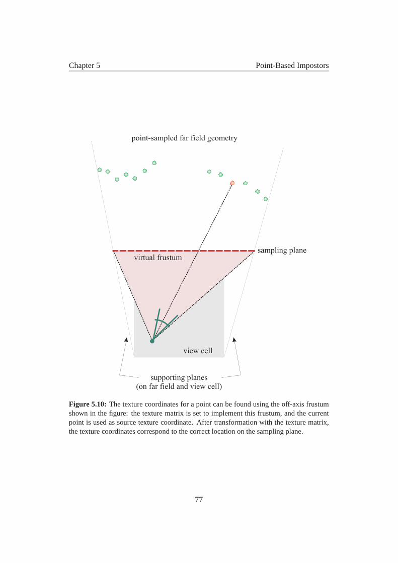
Chapter 5 Point-Based Impostors
view cell
sampling plane
point-sampled far field geometry
supporting planes(on far field and view cell)
virtual frustum
Figure 5.10: The texture coordinates for a point can be found using the off-axis frustumshown in the figure: the texture matrix is set to implement this frustum, and the currentpoint is used as source texture coordinate. After transformation with the texture matrix,the texture coordinates correspond to the correct location on the sampling plane.
77
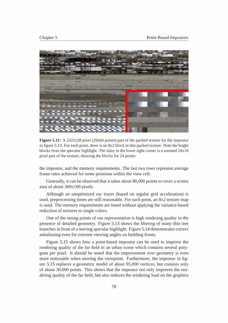
Chapter 5 Point-Based Impostors
Figure 5.11: A 232x128 pixel (29x64 points) part of the packed texture for the impostorin figure 5.13. For each point, there is an 8x2 block in this packed texture. Note the brightblocks from the specular highlight. The inlay in the lower right corner is a zoomed 24x16pixel part of the texture, showing the blocks for 24 points.
the impostor, and the memory requirements. The last two rows represent averageframe rates achieved for some positions within the view cell.
Generally, it can be observed that it takes about 80,000 points to cover a screenarea of about 300x100 pixels.
Although an unoptimized ray tracer (based on regular grid acceleration) isused, preprocessing times are still reasonable. For each point, an 8x2 texture mapis used. The memory requirements are listed without applying the variance-basedreduction of textures to single colors.
One of the strong points of our representation is high rendering quality in thepresence of detailed geometry. Figure 5.13 shows the filtering of many thin treebranches in front of a moving specular highlight. Figure 5.14 demonstrates correctantialiasing even for extreme viewing angles on building fronts.
Figure 5.15 shows how a point-based impostor can be used to improve therendering quality of the far field in an urban scene which contains several poly-gons per pixel. It should be noted that the improvement over geometry is evenmore noticeable when moving the viewpoint. Furthermore, the impostor in fig-ure 5.15 replaces a geometric model of about 95,000 vertices, but consists onlyof about 30,000 points. This shows that the impostor not only improves the ren-dering quality of the far field, but also reduces the rendering load on the graphics
78
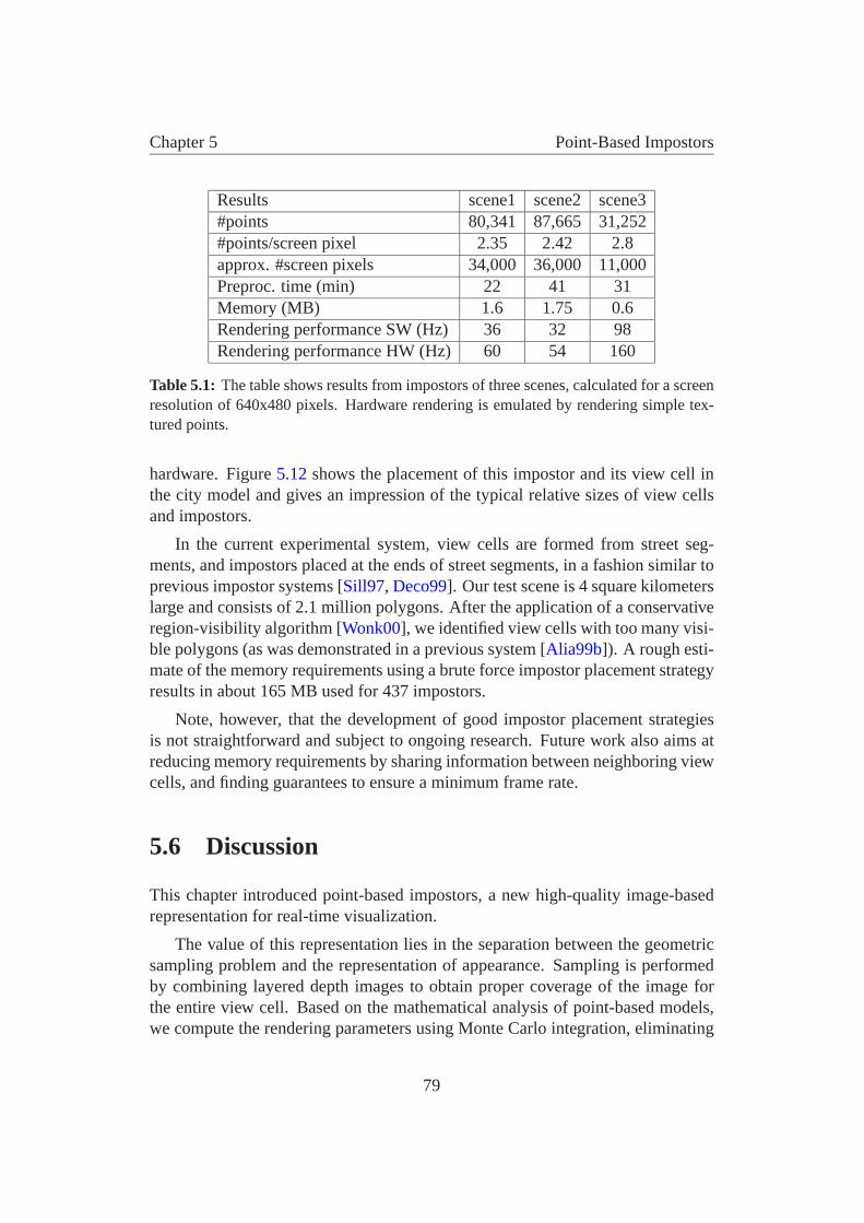
Chapter 5 Point-Based Impostors
Results scene1 scene2 scene3#points 80,341 87,665 31,252#points/screen pixel 2.35 2.42 2.8approx. #screen pixels 34,000 36,000 11,000Preproc. time (min) 22 41 31Memory (MB) 1.6 1.75 0.6Rendering performance SW (Hz) 36 32 98Rendering performance HW (Hz) 60 54 160
Table 5.1: The table shows results from impostors of three scenes, calculated for a screenresolution of 640x480 pixels. Hardware rendering is emulated by rendering simple tex-tured points.
hardware. Figure 5.12 shows the placement of this impostor and its view cell inthe city model and gives an impression of the typical relative sizes of view cellsand impostors.
In the current experimental system, view cells are formed from street seg-ments, and impostors placed at the ends of street segments, in a fashion similar toprevious impostor systems [Sill97, Deco99]. Our test scene is 4 square kilometerslarge and consists of 2.1 million polygons. After the application of a conservativeregion-visibility algorithm [Wonk00], we identified view cells with too many visi-ble polygons (as was demonstrated in a previous system [Alia99b]). A rough esti-mate of the memory requirements using a brute force impostor placement strategyresults in about 165 MB used for 437 impostors.
Note, however, that the development of good impostor placement strategiesis not straightforward and subject to ongoing research. Future work also aims atreducing memory requirements by sharing information between neighboring viewcells, and finding guarantees to ensure a minimum frame rate.
5.6 Discussion
This chapter introduced point-based impostors, a new high-quality image-basedrepresentation for real-time visualization.
The value of this representation lies in the separation between the geometricsampling problem and the representation of appearance. Sampling is performedby combining layered depth images to obtain proper coverage of the image forthe entire view cell. Based on the mathematical analysis of point-based models,we compute the rendering parameters using Monte Carlo integration, eliminating
79
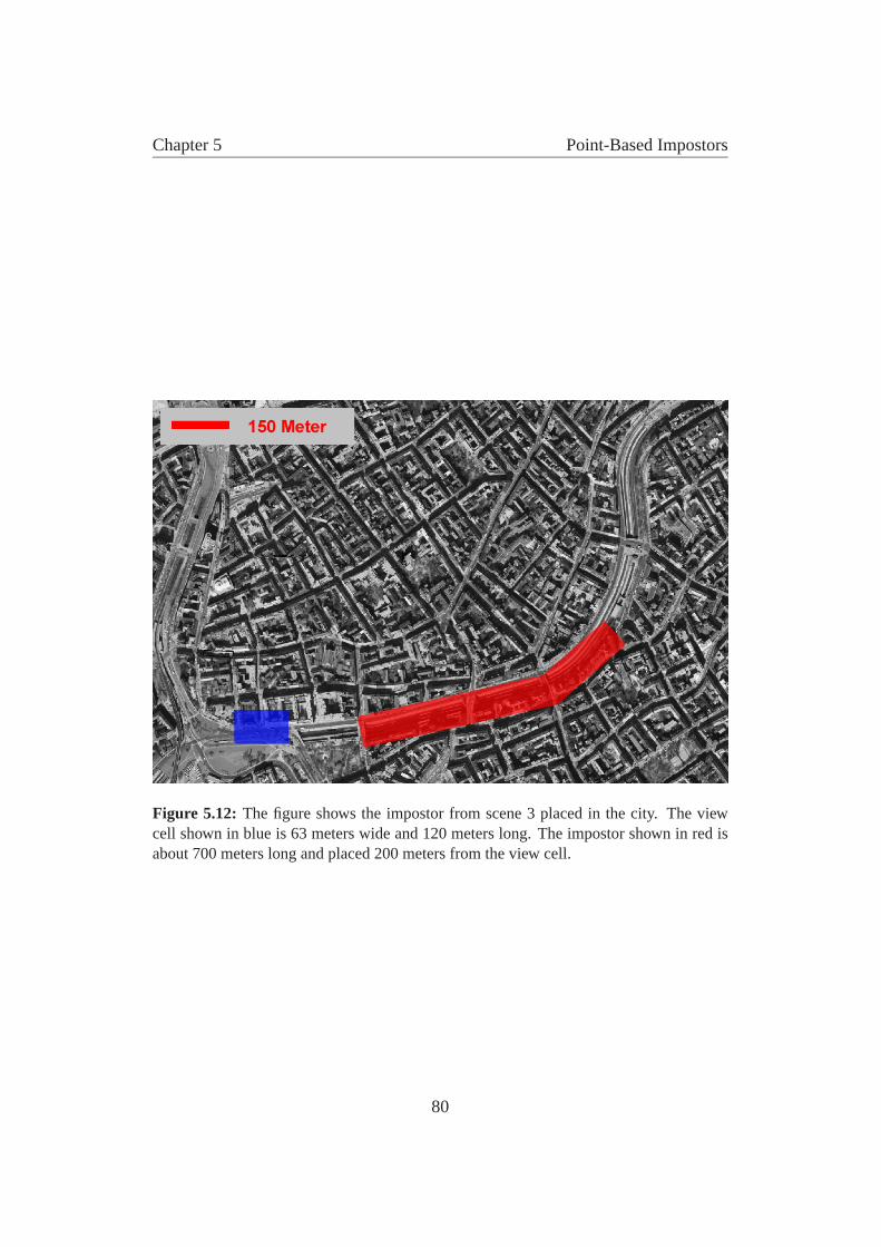
Chapter 5 Point-Based Impostors
Figure 5.12: The figure shows the impostor from scene 3 placed in the city. The viewcell shown in blue is 63 meters wide and 120 meters long. The impostor shown in red isabout 700 meters long and placed 200 meters from the view cell.
80

Chapter 5 Point-Based Impostors
Figure 5.13: Note the correct filtering of the trees against the building front and the spec-ular highlight in the windows for the impostor (top), and severe aliasing in the trees forgeometry (bottom).
most of the aliasing artifacts. Rendering information is compactly encoded andcan be rendered on contemporary hardware. Point-based impostors show greatpromise for all situations in which a geometrically very complex model consti-tutes the far field, such as in urban walkthroughs of detailed models. The render-ing times indicate that this representation is applicable to real-time visualizationapplications, where frame times above 60 Hz are required.
81
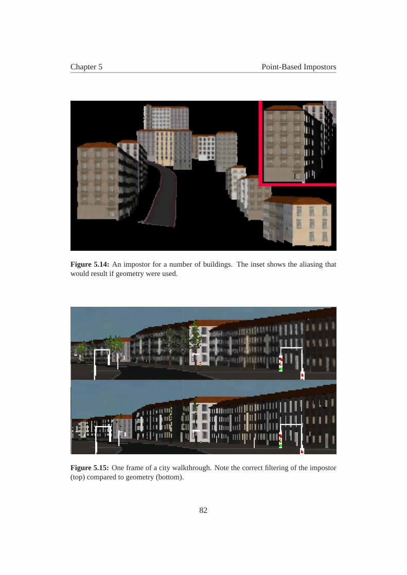
Chapter 5 Point-Based Impostors
Figure 5.14: An impostor for a number of buildings. The inset shows the aliasing thatwould result if geometry were used.
Figure 5.15: One frame of a city walkthrough. Note the correct filtering of the impostor(top) compared to geometry (bottom).
82
Chapter 6
Conclusions and Future Work
Although computers continue to get faster and faster, real-time rendering is farfrom being a solved problem. As long as the geometric model of a car or a sim-ple mechanical part is able to overwhelm the rendering capabilities of the fastestavailable graphics hardware, this situation is not going to change. Currently, it ispossible to render small urban models, but at the expense of visual richness—weare therefore still striving for bigger models, and more visual detail at the sametime.
The quest for true real-time rendering on arbitrary models is marked by the ne-cessity to identify opportunities to reduce complexity. This automatically bringsthe human visual system and its interface to the computer—images—into play:Details can only be omitted if they are not important to the viewer, wherever heis located. Purely image-based techniques follow this road to the end and equateperceived complexity with the resolution of an image, and totally abandon geom-etry. Such approaches have their limitations, however, because viewer locationscannot be easily predicted in a real-time application, and the complexity of manyimages can quickly be disproportionate to the complexity inherent to the geomet-ric model.
In this thesis, we take a different approach. Instead of being bound to thecomplexity of the underlying model, or the complexity of an image, we exploita general property of several types of scenes: due to perspective viewing, com-plexity per screen area increases with increasing distance, but at the same time,the importance of distant objects diminishes. Distant objects are therefore per-fectly amenable to simplification. This thesis presents two ways to do exactlythat: simplify distant geometry.
83
Chapter 6 Conclusions and Future Work
6.1 Synopsis
The topic of this thesis is a set of algorithms for fast and high quality displayof distant geometry. Two major algorithms were presented: an online methodthat requires no preprocessing, and an offline method that offers very high visualquality.
The online method is based on the observation that in many walkthrough sce-narios, only a small area of the screen is covered by actual distant geometry. Thepixels in that area are found via an opacity buffer, and a horizon map is used toinclude only pixels which belong to actual geometry and not to sky. A panoramicimage cache allows rotational motion with correct reprojection. Translationalmovement exploits the coherence between successive images to keep errors low.Finally, incorrect pixels are traced via a fast ray caster.
The offline method uses precomputed point-based impostors to represent dis-tant geometry. The impostors are calculated so that they provide a good approx-imation to the real geometry for a specific view cell. Point samples are obtainedby carefully sampling the geometry with three perspective LDIs, ensuring a well-distributed density of point samples over the range of valid viewpoints. Holes areavoided by tightly oversampling the LDIs depending on the desired output reso-lution. A new mathematical formulation for the appearance of a point is shown,based on the plenoptic image function. This allows us to encode directionallydependent appearance information in a texture map for each point. The texturevalues are chosen so as to provide the best possible appearance of the impostor forany viewpoint located in the view cell. The result is an antialiased representationfor distant geometry that can be fully rendered with current graphics hardware.
The remainder of this chapter will deal with the specific advantages and disad-vantages of the two methods. Some limitations are discussed, and finally, a rangeof suggestions for future research is presented.
6.2 Advantages
Distant geometry can be enormously complex, and both methods presented resultin a drastic reduction of geometric primitives that have to be rendered overall. Thiscan be used twofold: It can make a scene practical that was originally too complexto be rendered interactively. For other scenes that can be rendered interactivelyalready, it allows adding visual detail to the near field and making the environmentmuch more appealing.
84
Chapter 6 Conclusions and Future Work
Both methods introduce the notion of output sensitivity into the setting of largescenes. While the distinction between near field and far field is not adaptive, it isstill valid to assume that near-field geometry is of bounded complexity. In thefirst method, far-field geometry is recognized directly in the image, therefore therendering time for the far field only depends on the number of pixels covered by it.The complexity of point-based impostors, on the other hand, can not be expressedin terms of the pixels of a single frame, as such an impostor has to be valid forall viewpoints of a view cell. Their complexity is, however, output sensitive inthe sense that only “relevant” pixels are taken into account when constructing therepresentation, i.e., pixels visible in any possible view from the view cell.
While output sensitivity is usually touted as a desirable feature of image-basedmethods, the algorithms in this thesis avoid a common pitfall associated with this:if there is too much “output”, then a strictly “output-sensitive” method will stillbe slow, even if the underlying scene complexity is little. By concentrating ongeometry that inherently covers only few pixels on the screen (i.e., little “output”),we make sure that output sensitivity is really desirable.
The ray casting method from chapter 4 is easy to set up and integrate into anexisting rendering system. There is no preprocessing overhead, so the scene maybe changed often or even dynamically. Furthermore, the technique is amenable toparallelization and can profit from a wealth of ray tracing acceleration research.
6.2.1 Specific advantages of point-based impostors
Point-based impostors, on the other side, require preprocessing and are there-fore limited to applications with little changing scenery. They blend with tra-ditional rendering techniques, so dynamic objects can always be rendered usingpolygons, even in the far field. Two significant advantages of point-based impos-tors are that they provide much higher quality rendering, and that they do this inmuch less time, because no online calculations are necessary. More precisely, thesmall amount of computations left for each frame can be offloaded to the graphicshardware, incurring almost no additional cost. Point-based impostors are particu-larly suited for distant geometry, because the mathematical formulation of pointsspecifically considers microgeometry, i.e., geometric features that project to lessthan a pixel. For distant geometry, several triangles usually project to a singlepixel.
We are aware of no other computer graphics method that can simplify distantgeometry in such a way, i.e. with:
• correct warping of geometry (so parallax effects are not lost)
85

Chapter 6 Conclusions and Future Work
• capturing of view-dependent effects such as specular highlights
• correct representation of microgeometry
• inherent antialiasing
• fast, hardware-accelerated rendering
For the purpose of real-time rendering, point-based impostors can be seenas the missing link between purely image-based representations such as lightfields, and purely geometry-based representations. Directional radiance infor-mation is stored where it is needed, i.e., at the geometric location of the realobject. Unlike surface light fields, however, no restriction on the type of geome-try exists—for example, trees can be nicely captured and rendered using point-based impostors. Unlike other approaches to incorporate geometry into lightfields [Gort96, Chai00], this parameterization of light fields (i.e., via points) canexploit the coherence in directional radiance usually found for many object lo-cations. On a diffuse surface point, only one value is necessary to store all theinformation. In the presence of microgeometry, the directionally dependent ap-pearance information can help to create the correct view of the “soup” of polygonsfrom different viewpoints.
6.3 Disadvantages and limitations
The techniques presented do have some limitations and offer ample room for fu-ture research. Both methods are not fully general, i.e., they do not work for arbi-trary scenes. A certain amount of occlusion is required to make the distributionbetween near field and far field work. This is to be expected, most accelerationalgorithms are designed to exploit certain features of some class of scenes.
The ray casting method, in particular, suffers from a considerable amount ofonline computation, which reduces the time available to render triangles. Thiscould be alleviated by using multiple CPUs to compute the opacity map, imagecache lookups and the rays themselves. The ray casting approach also dependson the efficiency of the ray caster for a particular scene. While most ray tracingoptimization schemes achieve sublinear performance with many scenes, severelynon-uniform scenes or other worst-case scenarios can easily thwart any optimiza-tion scheme.
The image quality of ray casting is at best equal to rendering geometry. If toomany pixels are in the far field and the method resorts to graceful degradation, notall necessary rays can be cast every frame. The result is a kind of cross-dissolve
86
Chapter 6 Conclusions and Future Work
effect on edges that move in the image (due to translational movement of theobserver). The effect looks similar to frameless rendering [Bish94], a techniquewhere pixels are updated independently of the display refresh signal. We observedgraceful degradation mainly if the border between near and far field was set toonear, and in wide open spaces.
Point-based impostors can be said to lie at the other end of the spectrum. Theyoffer vastly superior image quality to the ray casting technique and even to stan-dard geometry rendering, and almost no overhead during runtime. The cost forthis quality and efficiency is a significant amount of preprocessing time. To com-pute all impostors for a larger urban scene, several hours of precomputation mightbe common.
Furthermore, point-based impostors cannot be used simply as a drop-in com-ponent to an existing rendering system. They require a good partitioning of theviewing space into view cells. Such a partitioning might be straightforward in thecase of some urban environments, but in general, the size and location for goodview cells is not obvious.
As in any offline method, there is the issue of storage space. Impostors fora larger city model might take up several hundreds of megabytes, depending onvisibility: if wide open views exist in many locations, more impostors have tobe used. If only a few locations offer views that stretch far away, the numberof impostors will be limited. This problem is directly related to the partitioninginto view cells. Since impostor information is not shared between view cells, afine-grained view space partition can significantly increase storage requirements.
Finally, points might not be the ultimate answer to far-field rendering. Sincewe rely on a sufficiently dense sampling of objects to avoid holes during recon-struction, an impostor usually requires twice as many points than pixels in a pro-jection from the view cell. This adds up to a lot of points, given that many of thosepoints will not significantly enhance the depth effect of the impostor. Neither is itpossible to approach the impostor nearer than the view cell allows, for example ifa close-up view is required and a new model (e.g., a new impostor for a differentview cell or simply geometry) is not yet available. In such a case, the representa-tion would show holes. Splatting with a kernel greater than a pixel could be usedin such a case, but only square splat kernels are available in hardware, providingonly mediocre quality.
A representation of the far field using triangles might be more desirable be-cause it maps better to current graphics hardware and has the ability to exploithardware interpolation and rasterization. Indeed, such representations have beenproposed [Sill97] for city models. However, we are aware of no triangle-basedfar-field representation that correctly captures geometry and appearance attributes
87
Chapter 6 Conclusions and Future Work
of the far field and that can deal with microgeometry. Point-based impostors candeal with arbitrarily complex geometry and do not rely on coherence of depthvalues from any viewpoint. They avoid common artifacts like rubber-sheet trian-gles, occlusion and disocclusion errors and others. Still, a triangle-based solutionshould be more efficient to render and take up less storage space.
6.4 Future work
In this section, future research directions and potential derivations from this workare discussed.
6.4.1 Triangle-based impostors
First and foremost, we believe that future research should concentrate on doingfor triangles what this thesis did for points. As already hinted at in the previoussection, triangles map better to current hardware (and this situation is not likelyto change in the near future). Triangles could exploit the rasterization capabilitiesof graphics cards, while points only make use of geometry acceleration. Thefollowing problems would have to be solved:
• Geometric sampling of the far field (the geometric sampling method pre-sented in this thesis would serve as a good starting point).
• Creation of connectivity (i.e., decide where to put triangles): this is actuallya difficult task, because no unique solution exists. The triangles would haveto faithfully represent the depth structure of the object from all points of theview cell.
• Simplification of the resulting triangle mesh. Standard polygonal simplifi-cation tools could be used for this step, but it is likely that better resultscan be achieved if the error metric used in the simplification process isadapted to the possible views on the object—this could be called “viewcell-dependent” simplification.
• Calculation and storage of appearance information in the resulting mesh,preferably with textures. This might of course influence the simplificationstep as well.
Point-based impostors avoid having to deal with these problems, at the cost ofincreased complexity (in terms of number of points) of the representation.
88
Chapter 6 Conclusions and Future Work
6.4.2 View cell partitioning
This thesis has introduced point-based impostors, a primitive destined to replacedistant geometry, providing fast and high quality rendering of such geometry. Wehave, however, not dealt with the question where to place these impostors in anactual city model. This leads directly to the second open question, how to partitionthe view space into view cells?
Both of these questions warrant closer attention in future research, not onlyfor point-based impostors, but for many impostor-based methods. Sillion et al.[Sill97] have proposed basing the view-space partitioning on the street graph. Inthis thesis, we have loosely followed this suggestion and obtained good results, buta serious fully automated system would have to tackle some unaddressed issues:
• If no street graph is available, what other a priori information about thescene can be used to aid the partitioning?
• How can impostor information be shared among adjacent view cells in orderto reduce storage requirements?
• What part of the far field should be converted to impostors, and what partshould be rendered using triangles? One suggestion is to set a polygon bud-get for each view cell and render the rest as impostors [Alia99b]. However,the size of the generated impostor should probably also enter into the cal-culation.
• Should view cells be rather large or small? How does the size of the chosenimpostor affect the efficiency of the representation?
At the moment, a semi-automatic process depending on the street graph isviable for medium-sized urban scenes. Larger and more general scenes requirean automatic process that places impostors where they are needed, optimizingrendering speed for all view cells and at the same time reducing overall storagerequirements.
6.4.3 Near-field and far-field distance
The ray casting and image caching technique would profit from studying the be-havior of the system with respect to scene complexity, overall “type” of the sceneand to the algorithm parameters. In particular, it would be interesting to automat-ically determine such parameters as back plane distance, number of rays to trace
89
Chapter 6 Conclusions and Future Work
per frame and grid resolution, so as to always provide near optimal performance.Determining the border between near field and far field automatically would adaptthe algorithm perfectly to different hardware systems. Buying a better graphicscard would allow to increase the far-field distance, while it could be decreasedif a faster CPU were used. The automatic level-of-detail management system byFunkhouser and Sequin [Funk93] provides valuable hints on how to do this.
Another interesting avenue of research for the ray casting method is the use ofgraphics hardware for the image-based operations that were introduced. With sys-tems that allow access to frame buffer and texture memory with the same speed asto the system memory, it might be possible to let the hardware do the reprojectionof the environment map onto the screen. For example, a simple extension to thecurrent system would be to use graphics hardware to create the opacity buffer.
6.5 Conclusion
We have presented two algorithms capable of considerably speeding up renderingof large virtual environments. Both algorithms are in their nature image-based.Both make some assumptions about the scenes they handle. We believe thatimage-based techniques such as the ones presented here are the way to go forthe simplification of distant geometry. We have also demonstrated that distantgeometry is indeed a very good candidate for simplification. What’s more, thesecond method even significantly improves the image quality of such geometry.
This thesis demonstrates clearly the tradeoff between online and offline tech-niques. Each of the two methods presented has its individual advantages, but noneof the two comes without a cost. It is up to the application to decide where thefocus lies: whether online or offline calculation is more important.
We have also shown that points are a valuable rendering primitive, but theycannot be used indiscriminately. Rendering points, especially for distant geome-try, requires a terse mathematical treatment. Decoupling geometry and appearancehas proven crucial for high-quality rendering of distant geometry, and points arewell suited to this particular task.
Concerning chapter 4, it seems that ray tracing is not to be discounted as a toolin real-time rendering. Supported by other image-based rendering techniques likea panoramic image cache or the horizon map, ray casting has proven to acceleratewalkthroughs of large virtual environments by an order of magnitude.
In conclusion, we observe that the last words on real-time rendering are notspoken, but we think that this thesis is a step in the right direction towards achiev-ing this valuable goal.
90
Bibliography
[Adel91] Edward H. Adelson and James R. Bergen. The Plenoptic Functionand the Elements of Early Vision. Computational Models of VisualProcessing, 1991. 20
[Aila01] Timo Aila and Ville Miettinen. Sur-Render Umbra – Reference Manual.http://www.surrender3d.com/umbra/index.html,2001. 15
[Aire90] John M. Airey, John H. Rohlf, and Frederick P. Brooks, Jr. TowardsImage Realism with Interactive Update Rates in Complex VirtualBuilding Environments. In Rich Riesenfeld and Carlo Sequin, edi-tors, Computer Graphics (1990 Symposium on Interactive 3D Graph-ics), volume 24, pages 41–50, March 1990. 11
[Alia97] Daniel G. Aliaga and Anselmo A. Lastra. Architectural Walk-throughs Using Portal Textures. In Roni Yagel and Hans Hagen,editors, Proceedings of the conference on Visualization ’97, pages355–362. IEEE, October 1997. 24, 60
[Alia99a] Daniel Aliaga, Jon Cohen, Andrew Wilson, Eric Baker, Han-song Zhang, Carl Erikson, Keny Hoff, Tom Hudson, WolfgangSturzlinger, Rui Bastos, Mary Whitton, Fred Brooks, and DineshManoclia. MMR: An Interactive Massive Model Rendering Sys-tem Using Geometric and Image-Based Acceleration. In Stephen N.Spencer, editor, 1999 Symposium on interactive 3D Graphics, pages199–206. ACM SIGGRAPH, ACM Press, April 1999. ISBN 1-58113-082-1. 19
[Alia99b] Daniel G. Aliaga and Anselmo Lastra. Automatic Image Placementto Provide a Guaranteed Frame Rate. In Alyn Rockwood, editor,SIGGRAPH 99 Conference Proceedings, Annual Conference Series,
91
Bibliography
pages 307–316. ACM SIGGRAPH, Addison Wesley, August 1999.79, 89
[Aman87] John Amanatides and Andrew Woo. A Fast Voxel Traversal Algo-rithm for Ray Tracing. In G. Marechal, editor, Eurographics ’87,pages 3–10. North-Holland, August 1987. 31, 48
[Appe68] Arthur Appel. Some Techniques for Shading Machine Renderingsof Solids. In AFIPS 1968 Spring Joint Computer Conference, vol-ume 32, pages 37–45, 1968. 30
[Arvo87] James Arvo and David Kirk. Fast Ray Tracing by Ray Classification.In Maureen C. Stone, editor, Computer Graphics (SIGGRAPH 87Proceedings), volume 21, pages 55–64, July 1987. 32
[Arvo89] James Arvo and David Kirk. A survey of ray tracing accelerationtechniques. In Andrew S. Glassner, editor, An introduction to raytracing, pages 201–262. Academic Press, 1989. 30
[Bish94] Gary Bishop, Henry Fuchs, Leonard McMillan, and Ellen J. ScherZagier. Frameless Rendering: Double Buffering Considered Harm-ful. In Andrew Glassner, editor, SIGGRAPH 94 Conference Proceed-ings, Annual Conference Series, pages 175–176. ACM SIGGRAPH,ACM Press, July 1994. ISBN 0-89791-667-0. 87
[Bitt98] Jiri Bittner, Vlastimil Havran, and Pavel Slavık. Hierarchical Vis-ibility Culling with Occlusion Trees. In Franz-Erich Wolter andNicholas M. Patrikalakis, editors, Proceedings of the Conference onComputer Graphics International 1998 (CGI-98), pages 207–219,Los Alamitos, California, June 22–26 1998. IEEE Computer Soci-ety. ISBN 0-8186-8445-3. 13
[Blin76] James F. Blinn and Martin E. Newell. Texture and Reflection in Com-puter Generated Images. Communications of the ACM, 19(10):542–547, October 1976. ISSN 0001-0782. 23
[Blin78] J. F. Blinn. Simulation of Wrinkled Surfaces. In Richard L.Phillips, editor, Computer Graphics (SIGGRAPH 78 Proceedings),volume 12, pages 286–292. ACM SIGGRAPH, ACM Press, August1978. 23
[Catm74] Edwin E. Catmull. A Subdivision Algorithm for Computer Display ofCurved Surfaces. Ph.D. Thesis, University of Utah, December 1974.28
92
Bibliography
[Catm75] Edwin E. Catmull. Computer Display of Curved Surfaces. In Pro-ceedings of the IEEE Conference on Computer Graphics, PatternRecognition, and Data Structure, pages 11–17, May 1975. 11
[Caza95] Frederic Cazals, George Drettakis, and Claude Puech. Filtering,Clustering and Hierarchy Construction: a New Solution for Ray-Tracing Complex Scenes. Computer Graphics Forum (Proc. Euro-graphics ’95), 14(3):371–382, August 1995. ISSN 1067-7055. 32
[Cert96] Andrew Certain, Jovan Popovic, Tony DeRose, Tom Duchamp,David Salesin, and Werner Stuetzle. Interactive Multiresolution Sur-face Viewing. In Holly Rushmeier, editor, SIGGRAPH 96 Confer-ence Proceedings, Annual Conference Series, pages 91–98. ACMSIGGRAPH, Addison Wesley, August 1996. held in New Orleans,Louisiana, 04-09 August 1996. 17
[Chai00] Jin-Xiang Chai, Xin Tong, Shing-Chow Chan, and Heung-YeungShum. Plenoptic Sampling. In Kurt Akeley, editor, SIGGRAPH 2000Conference Proceedings, Annual Conference Series, pages 307–318.ACM SIGGRAPH, Addison Wesley, 2000. 21, 64, 86
[Cham96] Bradford Chamberlain, Tony DeRose, Dani Lischinski, DavidSalesin, and John Snyder. Fast Rendering of Complex Environ-ments Using a Spatial Hierarchy. In Wayne A. Davis and RichardBartels, editors, Proceedings of Graphics Interface ’96, pages 132–141. Canadian Information Processing Society, Canadian Human-Computer Communications Society, May 1996. ISBN 0-9695338-5-3. 39
[Chan99] Chun-Fa Chang, Gary Bishop, and Anselmo Lastra. LDI Tree: AHierarchical Representation for Image-Based Rendering. In AlynRockwood, editor, SIGGRAPH 99 Conference Proceedings, An-nual Conference Series, pages 291–298. ACM SIGGRAPH, AddisonWesley, August 1999. 25, 26
[Chen93] Shenchang Eric Chen and Lance Williams. View Interpolation forImage Synthesis. In James T. Kajiya, editor, SIGGRAPH 93 Confer-ence Proceedings, Annual Conference Series, pages 279–288. ACMSIGGRAPH, Addison Wesley, August 1993. ISBN 0-201-51585-7.22, 25
[Chen95] Shenchang Eric Chen. Quicktime VR - An Image-Based Approachto Virtual Environment Navigation. In Robert Cook, editor, SIG-GRAPH 95 Conference Proceedings, Annual Conference Series,
93

Bibliography
pages 29–38. ACM SIGGRAPH, Addison Wesley, August 1995.held in Los Angeles, California, 06-11 August 1995. 22, 49
[Clar76] James H. Clark. Hierarchical Geometric Models for Visible SurfaceAlgorithms. Communications of the ACM, 19(10):547–554, October1976. ISSN 0001-0782. 11, 16
[Clea88] John G. Cleary and Geoff Wyvill. Analysis of an algorithm for fastray tracing using uniform space subdivision. The Visual Computer,4(2):65–83, July 1988. 33
[Cohe98a] Jonathan Cohen, Marc Olano, and Dinesh Manocha. Appearance-Preserving Simplification. In Michael Cohen, editor, SIGGRAPH 98Conference Proceedings, Annual Conference Series, pages 115–122.ACM SIGGRAPH, Addison Wesley, July 1998. ISBN 0-89791-999-8. 18
[Cohe98b] Daniel Cohen-Or, Gadi Fibich, Dan Halperin, and Eyal Zadicario.Conservative Visibility and Strong Occlusion for Viewspace Parti-tioning of Densely Occluded Scenes. Computer Graphics Forum(Proc. Eurographics ’98), 17(3):243–254, September 1998. ISSN1067-7055. 14
[Coor97] Satyan Coorg and Seth Teller. Real-Time Occlusion Culling forModels with Large Occluders. In Michael Cohen and David Zeltzer,editors, 1997 Symposium on Interactive 3D Graphics, pages 83–90.ACM SIGGRAPH, April 1997. ISBN 0-89791-884-3. 13
[Coor99] Satyan Coorg and Seth Teller. Temporally Coherent ConservativeVisibility. Computational Geometry: Theory and Applications, 12(1-2):105–124, February 1999. 13, 72
[Corp01] NVIDIA Corporation. NVIDIA OpenGLSpecifications, 2001. available athttp://www.nvidia.com/Marketing/Developer/DevRel.nsf/Program10, 25
[Dars97] Lucia Darsa, Bruno Costa Silva, and Amitabh Varshney. NavigatingStatic Environments Using Image-Space Simplification and Morph-ing. In Michael Cohen and David Zeltzer, editors, 1997 Symposiumon Interactive 3D Graphics, pages 25–34. ACM SIGGRAPH, ACMPress, April 1997. ISBN 0-89791-884-3. 27
94
Bibliography
[De F97] Leila De Floriani, Paola Magillo, and Enrico Puppo. Building andTraversing a Surface at Variable Resolution. In Roni Yagel and HansHagen, editors, Proceedings of the conference on Visualization ’97,pages 103–110. IEEE, October 1997. 18
[Deco99] Xavier Decoret, Francois Sillion, Gernot Schaufler, and Julie Dorsey.Multi-layered impostors for accelerated rendering. Computer Graph-ics Forum (Proc. Eurographics ’99), 18(3):61–73, September 1999.ISSN 1067-7055. 27, 79
[Dura97] Fredo Durand, George Drettakis, and Claude Puech. The VisibilitySkeleton: A Powerful and Efficient Multi-Purpose Global VisibilityTool. In Turner Whitted, editor, SIGGRAPH 97 Conference Proceed-ings, Annual Conference Series, pages 89–100. ACM SIGGRAPH,Addison Wesley, August 1997. ISBN 0-89791-896-7. 14
[Dura99] Fredo Durand. 3D Visibility: Analytical Study and Applications. PhDthesis, Universite Joseph Fourier, Grenoble, France, July 1999. 15
[Dura00] Fredo Durand, George Drettakis, Joelle Thollot, and Claude Puech.Conservative Visibility Preprocessing Using Extended Projections.In Kurt Akeley, editor, SIGGRAPH 2000 Conference Proceedings,Annual Conference Series, pages 239–248. ACM SIGGRAPH, Ad-dison Wesley, July 2000. 14
[Eck95] Matthias Eck, Tony DeRose, Tom Duchamp, Hugues Hoppe,Michael Lounsbery, and Werner Stuetzle. Multiresolution Analysisof Arbitrary Meshes. In Robert Cook, editor, SIGGRAPH 95 Confer-ence Proceedings, Annual Conference Series, pages 173–182. ACMSIGGRAPH, Addison Wesley, August 1995. held in Los Angeles,California, 06-11 August 1995. 17
[Ecke98] George Eckel, Renate Kempf, and Leif Wennerberg. OpenGL Opti-mizer Programmer’s Guide: An Open API for Large-Model Visual-ization. SGI techpubs library, 1998. Document Number 007-2852-002. 10
[Ecke00] George Eckel and Ken Jones. OpenGL Performer Programmer’sGuide. SGI techpubs library, 2000. Document Number 007-1680-060. 10
[Fuch80] Henry Fuchs, Zvi M. Kedem, and Bruce F. Naylor. On Visible Sur-face Generation by a Priori Tree Structures. In James J. Thomas, ed-
95
Bibliography
itor, Computer Graphics (SIGGRAPH 80 Proceedings), volume 14,pages 124–133. ACM SIGGRAPH, ACM Press, July 1980. 11
[Fuji86] Akira Fujimoto, Takayuki Tanaka, and Kansei Iwata. ARTS: Accel-erated Ray Tracing System. IEEE Computer Graphics and Applica-tions, 6(4):16–26, 1986. 31
[Funk93] Thomas A. Funkhouser and Carlo H. Sequin. Adaptive Display Al-gorithm for Interactive Frame Rates During Visualization of Com-plex Virtual Environments. In James T. Kajiya, editor, SIGGRAPH93 Conference Proceedings, Annual Conference Series, pages 247–254. ACM SIGGRAPH, Addison Wesley, August 1993. ISBN 0-201-51585-7. 16, 90
[Fuss88] Donald S. Fussell and K. R. Subramanian. Fast Ray Tracing Us-ing K-d Trees. Technical Report CS-TR-88-07, University of Texas,Austin, March 1, 1988. 32
[Garl97] Michael Garland and Paul S. Heckbert. Surface Simplification UsingQuadric Error Metrics. In Turner Whitted, editor, SIGGRAPH 97Conference Proceedings, Annual Conference Series, pages 209–216.ACM SIGGRAPH, Addison Wesley, August 1997. ISBN 0-89791-896-7. 18
[Garl98] Michael Garland and Paul S. Heckbert. Simplifying Surfaces withColor and Texture using Quadric Error Metrics. In David Ebert, HansHagen, and Holly Rushmeier, editors, Proceedings of the conferenceon Visualization ’98, pages 263–270. IEEE, October 1998. ISBN1-58113-106-2. 18
[Giga90] Michael Gigante. Accelerated Ray Tracing Using Non-UniformGrids. In Proceedings of Ausgraph ’90, pages 157–163, Melbourne,Australia, September 1990. 32
[Gigu91] Ziv Gigus, J. Canny, and R. Seidel. Efficiently computing and rep-resenting aspect graphs of polyhedral objects. IEEE Transactionson Pattern Analysis and Machine Intelligence, 13(6):542–551, 1991.14
[Glas84] Andrew S. Glassner. Space Subdivision For Fast Ray Tracing. IEEEComputer Graphics and Applications, 4(10):15–22, October 1984.ISSN 0272-1716. 32
96
Bibliography
[Glas95] Andrew S. Glassner. Principles of Digital Image Synthesis. MorganKaufmann, San Francisco, CA, 1995. 8, 33
[Gold87] Jeffrey Goldsmith and John Salmon. Automatic Creation of ObjectHierarchies for Ray Tracing. IEEE Computer Graphics and Appli-cations, 7(5):14–20, May 1987. ISSN 0272-1716. 32
[Gort96] Steven J. Gortler, Radek Grzeszczuk, Richard Szeliski, andMichael F. Cohen. The Lumigraph. In Holly Rushmeier, editor,SIGGRAPH 96 Conference Proceedings, Annual Conference Series,pages 43–54. ACM SIGGRAPH, Addison Wesley, August 1996.held in New Orleans, Louisiana, 04-09 August 1996. 21, 86
[Gree86] Ned Greene. Environment Mapping and Other Applications of WorldProjection. IEEE Computer Graphics and Applications, 6(11):21–29, November 1986. ISSN 0272-1716. 23
[Gree93] Ned Greene and Michael Kass. Hierarchical Z-Buffer Visibility. InJames T. Kajiya, editor, SIGGRAPH 93 Conference Proceedings,Annual Conference Series, pages 231–238. ACM SIGGRAPH, Ad-dison Wesley, August 1993. ISBN 0-201-51585-7. 12
[Gros98] J. P. Grossman and William J. Dally. Point Sample Rendering. InGeorge Drettakis and Nelson Max, editors, Rendering Techniques’98 (Proceedings of the Eurographics Workshop on Rendering 98),pages 181–192. Eurographics, Springer-Verlag Wien New York,June 1998. 28, 68
[Hain86] Eric A. Haines and Donald P. Greenberg. The Light Buffer: A RayTracer Shadow Testing Accelerator. IEEE Computer Graphics andApplications, 6(9):6–16, September 1986. 32
[Hain91] Eric A. Haines and John R. Wallace. Shaft Culling for Efficient Ray-Cast Radiosity. In Pere Brunet and Frederik W. Jansen, editors, Pho-torealistic Rendering in Computer Graphics (Proceedings of the Eu-rographics Workshop on Rendering 91), pages 122–138. Eurograph-ics, Springer-Verlag Berlin Heidelberg New York, 1991. 32
[Heck89] Paul S. Heckbert. Fundamentals of Texture Mapping and ImageWarping. M.Sc. Thesis, Department of Electrical Engineering andComputer Science, University of California, Berkeley, June 1989.23
97
Bibliography
[Heid98] Wolfgang Heidrich, Jan Kautz, Philipp Slusallek, and Hans-PeterSeidel. Canned Lightsources. In George Drettakis and NelsonMax, editors, Rendering Techniques ’98 (Proceedings of the Euro-graphics Workshop on Rendering 98), pages 293–300. Eurographics,Springer-Verlag Wien New York, June 1998. 22
[Helm94] James L. Helman. Architecture and Performance of EntertainmentSystems, Appendix A. ACM SIGGRAPH 94 Course Notes - Design-ing Real-Time Graphics for Entertainment, 23:1.19–1.32, July 1994.7, 8, 9
[Hopp93] Hugues Hoppe, Tony DeRose, Tom Duchamp, John McDonald, andWerner Stuetzle. Mesh Optimization. In James T. Kajiya, editor,SIGGRAPH 93 Conference Proceedings, Annual Conference Series,pages 19–26. ACM SIGGRAPH, Addison Wesley, August 1993.ISBN 0-201-51585-7. 17, 18
[Hopp96] Hugues Hoppe. Progressive Meshes. In Holly Rushmeier, editor,SIGGRAPH 96 Conference Proceedings, Annual Conference Series,pages 99–108. ACM SIGGRAPH, Addison Wesley, August 1996.held in New Orleans, Louisiana, 04-09 August 1996. 18
[Hopp97] Hugues Hoppe. View-Dependent Refinement of Progressive Meshes.In Turner Whitted, editor, SIGGRAPH 97 Conference Proceedings,Annual Conference Series, pages 189–198. ACM SIGGRAPH, Ad-dison Wesley, August 1997. ISBN 0-89791-896-7. 18
[Huds97] T. Hudson, D. Manocha, J. Cohen, M. Lin, K. Hoff, and H. Zhang.Accelerated Occlusion Culling using Shadow Frusta. In Proceedingsof the 13th Annual ACM Symposium on Computational Geometry,pages 1–10. ACM Press, 4–6 June 1997. ISBN 0-89791-878-9. 13
[Isak00] Aaron Isaksen, Leonard McMillan, and Steven J. Gortler. Dynam-ically Reparameterized Light Fields. In Kurt Akeley, editor, SIG-GRAPH 2000 Conference Proceedings, Annual Conference Series,pages 297–306. ACM SIGGRAPH, Addison Wesley, 2000. 22
[Jeva89] David Jevans and Brian Wyvill. Adaptive voxel subdivision for raytracing. In Proceedings of Graphics Interface ’89, pages 164–172,June 1989. 32
[Jone94] Michael Jones. Lessons Learned from Visual Simulation. ACM SIG-GRAPH 94 Course Notes - Designing Real-Time Graphics for Enter-tainment, 23:2.1–2.34, July 1994. 8
98

Bibliography
[Kapl87] Michael R. Kaplan. The Use of Spatial Coherence in Ray Tracing.In David E. Rogers and Ray A. Earnshaw, editors, Techniques forComputer Graphics, pages 173–193. Springer Verlag, 1987. 32, 33
[Kay86] Timothy L. Kay and James T. Kajiya. Ray Tracing Complex Scenes.In David C. Evans and Russell J. Athay, editors, Computer Graphics(SIGGRAPH 86 Proceedings), volume 20, pages 269–278, August1986. 32
[Kilg97] Mark J. Kilgard. Realizing OpenGL: Two Implementations of OneArchitecture. In Steven Molnar and Bengt-Olaf Schneider, editors,1997 SIGGRAPH / Eurographics Workshop on Graphics Hardware,pages 45–56, New York City, NY, August 1997. ACM SIGGRAPH /Eurographics, ACM Press. ISBN 0-89791-961-0. 55
[Klim97] Krzysztof S. Klimaszewski and Thomas W. Sederberg. Faster RayTracing Using Adaptive Grids. IEEE Computer Graphics and Appli-cations, 17(1):42–51, January 1997. 32
[Lave94] Stephane Laveau and Olivier Faugeras. 3-D Scene Representationas a Collection of Images and Fundamental Matrices. In TwelfthInternational Conference on Pattern Recognition (ICPR’94), pages689–691. IEEE Computer Society Press, October 1994. 25
[Leht00] Lasse Lehtinen. 3Dfx Voodoo and Voodoo 2 FAQ, 2000. availableat http://user.sgic.fi/˜blob/Voodoo-FAQ/. 2
[Levo85] Marc Levoy and Turner Whitted. The Use of Points as Display Prim-itives. Technical Report TR85-022, Department of Computer Sci-ence, University of North Carolina - Chapel Hill, October 1 1985.28
[Levo96] Marc Levoy and Pat Hanrahan. Light Field Rendering. In HollyRushmeier, editor, SIGGRAPH 96 Conference Proceedings, AnnualConference Series, pages 31–42. ACM SIGGRAPH, Addison Wes-ley, August 1996. held in New Orleans, Louisiana, 04-09 August1996. 21
[Lind00] Peter Lindstrom and Greg Turk. Image-Driven Simplification. ACMTransactions on Graphics, 19(3):204–241, July 2000. 18
[Lipp80] Andrew Lippman. Movie-Maps: An application of the opticalvideodisc to computer graphics. In James J. Thomas, editor, Com-puter Graphics (SIGGRAPH 80 Proceedings), volume 14, pages 32–42. ACM SIGGRAPH, ACM Press, July 1980. 23
99

Bibliography
[Lisc98] Dani Lischinski and Ari Rappoport. Image-Based Rendering forNon-Diffuse Synthetic Scenes. In George Drettakis and NelsonMax, editors, Rendering Techniques ’98 (Proceedings of the Euro-graphics Workshop on Rendering 98), pages 301–314. Eurographics,Springer-Verlag Wien New York, June 1998. 29, 68
[Loun97] Michael Lounsbery, Tony D. DeRose, and Joe Warren. Multireso-lution Analysis for Surfaces of Arbitrary Topological Type. ACMTransactions on Graphics, 16(1):34–73, January 1997. ISSN 0730-0301. 17
[Lueb95] David P. Luebke and Chris Georges. Portals and Mirrors: Simple,Fast Evaluation of Potentially Visible Sets. In Pat Hanrahan andJim Winget, editors, 1995 Symposium on Interactive 3D Graphics,pages 105–106. ACM SIGGRAPH, ACM Press, April 1995. ISBN0-89791-736-7. 11
[Lueb97] David Luebke and Carl Erikson. View-Dependent Simplificationof Arbitrary Polygonal Environments. In Turner Whitted, editor,SIGGRAPH 97 Conference Proceedings, Annual Conference Series,pages 199–208. ACM SIGGRAPH, Addison Wesley, August 1997.ISBN 0-89791-896-7. 17
[Maci95] Paulo W. C. Maciel and Peter Shirley. Visual Navigation of LargeEnvironments Using Textured Clusters. In Pat Hanrahan and JimWinget, editors, 1995 Symposium on Interactive 3D Graphics, pages95–102. ACM SIGGRAPH, ACM Press, April 1995. ISBN 0-89791-736-7. 23
[Mark97] William R. Mark, Leonard McMillan, and Gary Bishop. Post-Rendering 3D Warping. In Michael Cohen and David Zeltzer, edi-tors, 1997 Symposium on Interactive 3D Graphics, pages 7–16. ACMSIGGRAPH, ACM Press, April 1997. ISBN 0-89791-884-3. 27
[Max96] Nelson Max. Hierarchical Rendering of Trees from PrecomputedMulti-Layer Z-Buffers. In Xavier Pueyo and Peter Schroder, editors,Rendering Techniques ’96 (Proceedings of the Eurographics Work-shop on Rendering 96), pages 165–174. Eurographics, Springer-Verlag Wien New York, June 1996. ISBN 3-211-82883-4. 25
[McMi95a] Leonard McMillan. Computing Visibility Without Depth. TechnicalReport TR95-047, Department of Computer Science, University ofNorth Carolina - Chapel Hill, October 1 1995. 26
100
Bibliography
[McMi95b] Leonard McMillan and Gary Bishop. Plenoptic Modeling: AnImage-Based Rendering System. In Robert Cook, editor, SIG-GRAPH 95 Conference Proceedings, Annual Conference Series,pages 39–46. ACM SIGGRAPH, Addison Wesley, August 1995.held in Los Angeles, California, 06-11 August 1995. 20, 25
[McMi97] Leonard McMillan. An Image-based Approach to Three-Dimensional Computer Graphics. Ph.D. Thesis, University of NorthCarolina at Chapel Hill, 1997. also available as UNC Technical Re-port TR97-013. 25
[Meye98] Alexandre Meyer and Fabrice Neyret. Interactive Volumetric Tex-tures. In George Drettakis and Nelson Max, editors, Rendering Tech-niques ’98 (Proceedings of the Eurographics Workshop on Rendering98), pages 157–168. Eurographics, Springer-Verlag Wien New York,June 1998. 26
[Mill98] Gavin Miller, Steven Rubin, and Dulce Ponceleon. Lazy Decom-pression of Surface Light Fields For Precomputed Global Illumina-tion. In George Drettakis and Nelson Max, editors, Rendering Tech-niques ’98 (Proceedings of the Eurographics Workshop on Rendering98), pages 281–292. Eurographics, Springer-Verlag Wien New York,June 1998. 22
[Moll97] Tomas Moller and Ben Trumbore. Fast, Minimum Storage Ray-Triangle Intersection. Journal of Graphics Tools, 2(1), 1997. ISSN1086-7651. 31
[Moll99a] Tomas Moller and Eric Haines. Real-Time Rendering, 1999. Web-page for book at http://www.realtimerendering.com.31
[Moll99b] Tomas Moller and Eric Haines. Real-Time Rendering. A. K. PetersLimited, 1999. 31
[NVID00a] NVIDIA Corporation. NV vertex program ex-tension specification, 2000. available athttp://www.nvidia.com/Marketing/Developer/DevRel.nsf/Program76
[NVID00b] NVIDIA Corporation. Using Texture Com-pression in OpenGL, 2000. available athttp://www.nvidia.com/Marketing/Developer/DevRel.nsf/Whitepa76
101
Bibliography
[Ohta87] Masataka Ohta and Mamoru Maekawa. Ray Coherence Theoremand Constant Time Ray Tracing Algorithm. In Tsiyasu L. Kunii,editor, Computer Graphics 1987 (Proceedings of CG International’87), pages 303–314. Springer-Verlag, 1987. 32, 33
[Oliv00] Manuel M. Oliveira, Gary Bishop, and David McAllister. Relief Tex-ture Mapping. In Kurt Akeley, editor, SIGGRAPH 2000 ConferenceProceedings, Annual Conference Series, pages 359–368. ACM SIG-GRAPH, Addison Wesley, July 2000. 26
[Park99] Steven Parker, William Martin, Peter-Pike J. Sloan, Peter Shirley,Brian Smits, and Charles Hansen. Interactive Ray Tracing. InStephen N. Spencer, editor, 1999 Symposium on interactive 3DGraphics, pages 119–126. ACM SIGGRAPH, ACM Press, April1999. ISBN 1-58113-082-1. 33
[Pfis00] Hanspeter Pfister, Matthias Zwicker, Jeroen van Baar, and MarkusGross. Surfels: Surface Elements as Rendering Primitives. InKurt Akeley, editor, SIGGRAPH 2000 Conference Proceedings, An-nual Conference Series, pages 335–342. ACM SIGGRAPH, AddisonWesley, 2000. 29, 65
[Plan90] Harry Plantinga and Charles R. Dyer. Visibility, Occlusion, and theAspect Graph. International Journal of Computer Vision, 5(2):137–160, November 1990. ISSN 0920-5691. 14
[Pope00] Voicu Popescu, John Eyles, Anselmo Lastra, Joshua Steinhurst, NickEngland, and Lars Nyland. The WarpEngine: An Architecture forthe Post-Polygonal Age. In Kurt Akeley, editor, SIGGRAPH 2000Conference Proceedings, Annual Conference Series, pages 433–442.ACM SIGGRAPH, Addison Wesley, July 2000. 26
[Powe01] PowerVR Technology Overview and Roadmap. PowerVRTechnology Overview and Roadmap, 2001. available athttp://www.powervr.com/WhitePapers/Whitepapers.htm.24
[Raff97] Matthew M. Rafferty, Daniel G. Aliaga, and Anselmo A. Lastra. 3DImage Warping in Architectural Walkthroughs. Technical ReportTR97-019, Department of Computer Science, University of NorthCarolina - Chapel Hill, September 03 1997. 24
102
Bibliography
[Rohl94] John Rohlf and James Helman. IRIS Performer: A High Perfor-mance Multiprocessing Toolkit for Real–Time 3D Graphics. In An-drew Glassner, editor, SIGGRAPH 94 Conference Proceedings, An-nual Conference Series, pages 381–395. ACM SIGGRAPH, ACMPress, July 1994. ISBN 0-89791-667-0. 10
[Ronf96] Remi Ronfard and Jarek Rossignac. Full-range Approximation ofTriangulated Polyhedra. Computer Graphics Forum (Proc. Euro-graphics ’96), 15(3):67–76, September 1996. ISSN 0167-7055. 18
[Ross93] Jarek Rossignac and Paul Borrel. Multi-resolution 3D approxima-tions for rendering complex scenes. In B. Falcidieno and T. Ku-nii, editors, Modeling in Computer Graphics: Methods and Appli-cations (Proc. Second Conference on Geometric Modelling in Com-puter Graphics, pages 455–465, Berlin, June 1993. Springer-Verlag.17
[Rubi80] Steven M. Rubin and Turner Whitted. A 3-Dimensional Representa-tion for Fast Rendering of Complex Scenes. In James J. Thomas, ed-itor, Computer Graphics (SIGGRAPH 80 Proceedings), volume 14,pages 110–116. ACM SIGGRAPH, ACM Press, July 1980. 32
[Rusi00] Szymon Rusinkiewicz and Marc Levoy. QSplat: A MultiresolutionPoint Rendering System for Large Meshes. In Kurt Akeley, editor,SIGGRAPH 2000 Conference Proceedings, Annual Conference Se-ries, pages 343–352. ACM SIGGRAPH, Addison Wesley, July 2000.30, 65
[Same89] Hanan J. Samet. Design and Analysis of Spatial Data Structures:Quadtrees, Octrees, and other Hierarchical Methods. Addison–Wesley, Redding, MA, 1989. 11
[Scha95a] Gernot Schaufler. Dynamically Generated Impostors. In Dieter W.Fellner, editor, GI Workshop on Modeling, Virtual Worlds,, pages129–135, November 1995. 23
[Scha95b] Gernot Schaufler and Wolfgang Sturzlinger. Generating MultipleLevels of Detail for Polygonal Geometry. In M. Gobel, editor, VirtualEnvironments ’95 (Second Eurographics Workshop in Virtual Envi-ronments 1995), pages 33–41. Springer Verlag, January 1995. 17
[Scha96] Gernot Schaufler and Wolfgang Sturzlinger. A Three-DimensionalImage Cache for Virtual Reality. Computer Graphics Forum (Proc.
103
Bibliography
Eurographics ’96), 15(3):227–235, September 1996. ISSN 0167-7055. 23
[Scha97] Gernot Schaufler. Nailboards: A Rendering Primitive for ImageCaching in Dynamic Scenes. In Julie Dorsey and Philipp Slusallek,editors, Rendering Techniques ’97 (Proceedings of the Eurograph-ics Workshop on Rendering 97), pages 151–162. Eurographics,Springer-Verlag Wien New York, June 1997. ISBN 3-211-83001-4.25
[Scha98] Gernot Schaufler. Per-Object Image Warping with Layered Impos-tors. In George Drettakis and Nelson Max, editors, Rendering Tech-niques ’98 (Proceedings of the Eurographics Workshop on Rendering98), pages 145–156. Springer-Verlag Wien New York, June 1998. 26
[Scha00] Gernot Schaufler, Julie Dorsey, Xavier Decoret, and Francois X. Sil-lion. Conservative Volumetric Visibility with Occluder Fusion. InKurt Akeley, editor, SIGGRAPH 2000 Conference Proceedings, An-nual Conference Series, pages 229–238. ACM SIGGRAPH, AddisonWesley, July 2000. 14
[Schi00] Hartmut Schirmacher, Wolfgang Heidrich, and Hans-Peter Seidel.High-Quality Interactive Lumigraph Rendering Through Warping.In Proceedings of Graphics Interface 2000, pages 87–94. MorganKaufman, May 2000. 22
[Schr92] William J. Schroeder, Jonathan A. Zarge, and William E. Lorensen.Decimation of triangle meshes. In Edwin E. Catmull, editor, Com-puter Graphics (SIGGRAPH 92 Proceedings), volume 26, pages 65–70. ACM SIGGRAPH, ACM Press, July 1992. ISSN 0097-8930.17
[Sega92] Mark Segal, Carl Korobkin, Rolf van Widenfelt, Jim Foran, and PaulHaeberli. Fast Shadows and Lighting Effects Using Texture Map-ping. In Edwin E. Catmull, editor, Computer Graphics (SIGGRAPH92 Proceedings), volume 26, pages 249–252. ACM SIGGRAPH,ACM Press, July 1992. ISSN 0097-8930. 23
[Seit96] Steven M. Seitz and Charles R. Dyer. View Morphing: Synthesizing3D Metamorphoses Using Image Transforms. In Holly Rushmeier,editor, SIGGRAPH 96 Conference Proceedings, Annual ConferenceSeries, pages 21–30. ACM SIGGRAPH, Addison Wesley, August1996. held in New Orleans, Louisiana, 04-09 August 1996. 23
104
Bibliography
[Shad96] Jonathan Shade, Dani Lischinski, David Salesin, Tony DeRose, andJohn Snyder. Hierarchical Image Caching for Accelerated Walk-throughs of Complex Environments. In Holly Rushmeier, editor,SIGGRAPH 96 Conference Proceedings, Annual Conference Series,pages 75–82. ACM SIGGRAPH, Addison Wesley, August 1996.held in New Orleans, Louisiana, 04-09 August 1996. 23
[Shad98] Jonathan W. Shade, Steven J. Gortler, Li-wei He, and RichardSzeliski. Layered Depth Images. In Michael Cohen, editor, SIG-GRAPH 98 Conference Proceedings, Annual Conference Series,pages 231–242. ACM SIGGRAPH, Addison Wesley, July 1998.ISBN 0-89791-999-8. 25
[Sill97] Francois Sillion, G. Drettakis, and B. Bodelet. Efficient ImpostorManipulationfor Real-Time Visualization of Urban Scenery. Com-puter Graphics Forum (Proc. Eurographics ’97), 16(3):207–218,August 1997. ISSN 1067-7055. 27, 79, 87, 89
[Simm00] Maryann Simmons and Carlo H. Sequin. Tapestry: A DynamicMesh-based Display Representation for Interactive Rendering. InBernard Peroche and Holly Rushmeier, editors, Rendering Tech-niques 2000 (Proceedings of the Eurographics Workshop on Ren-dering 2000), pages 329–340. Eurographics, Springer-Verlag WienNew York, June 2000. ISBN 3-211-83535-0. 24
[Sloa97] Peter-Pike Sloan, Michael F. Cohen, and Steven J. Gortler. TimeCritical Lumigraph Rendering. In Michael Cohen and David Zeltzer,editors, 1997 Symposium on Interactive 3D Graphics, pages 17–24.ACM SIGGRAPH, ACM Press, April 1997. ISBN 0-89791-884-3.22
[Snyd87] John M. Snyder and Alan H. Barr. Ray Tracing Complex Mod-els Containing Surface Tessellations. In Maureen C. Stone, editor,Computer Graphics (SIGGRAPH 87 Proceedings), volume 21, pages119–128, July 1987. 32
[Subr91] K. R. Subramanian and Donald S. Fussell. Automatic TerminationCriteria for Ray Tracing Hierarchies. In Proceedings of GraphicsInterface ’91, pages 93–100, June 1991. 32
[Suda96] Oded Sudarsky and Craig Gotsman. Output-Sensitive Visibility Al-gorithms for Dynamic Scenes with Applications to Virtual Reality.
105
Bibliography
Computer Graphics Forum (Proc. Eurographics ’96), 15(3):249–258, August 1996. ISSN 0167-7055. 44
[Sung91] Kelvin Sung. A DDA Octree Traversal Algorithm for Ray Tracing. InWerner Purgathofer, editor, Eurographics ’91, pages 73–85. North-Holland, September 1991. 32
[Tell91] Seth J. Teller and Carlo H. Sequin. Visibility Preprocessing for In-teractive Walkthroughs. In Thomas W. Sederberg, editor, ComputerGraphics (SIGGRAPH 91 Proceedings), volume 25, pages 61–69.ACM SIGGRAPH, ACM Press, July 1991. 11
[Tell92] Seth J. Teller. Computing the antipenumbra of an area light source.In Edwin E. Catmull, editor, Computer Graphics (SIGGRAPH 92Proceedings), volume 26, pages 139–148. ACM SIGGRAPH, ACMPress, July 1992. ISSN 0097-8930. 14
[Torb96] Jay Torborg and Jim Kajiya. Talisman: Commodity Real-time 3DGraphics for the PC. In Holly Rushmeier, editor, SIGGRAPH 96Conference Proceedings, Annual Conference Series, pages 353–364.ACM SIGGRAPH, Addison Wesley, August 1996. held in New Or-leans, Louisiana, 04-09 August 1996. 24
[Turk92] Greg Turk. Re-tiling polygonal surfaces. In Computer Graphics(SIGGRAPH 92 Proceedings), volume 26, pages 55–64. ACM SIG-GRAPH, ACM Press, July 1992. ISSN 0097-8930. 17
[Walt99] Bruce Walter, George Drettakis, and Steven Parker. Interactive Ren-dering using Render Cache. In Dani Lischinski and Greg Ward Lar-son, editors, Rendering Techniques ’99 (Proceedings of the Euro-graphics Workshop on Rendering 99), pages 19–30. Eurographics,Springer-Verlag Wien New York, June 1999. ISBN 3-211-83382-X.24
[Ward99] Gregory Ward and Maryann Simmons. The holodeck ray cache: aninteractive rendering system for global illumination in nondiffuse en-vironments. ACM Transactions on Graphics, 18(4):361–398, Octo-ber 1999. ISSN 0730-0301. 24
[Wegh84] Hank Weghorst, Gary Hooper, and Donald P. Greenberg. ImprovedComputational Methods for Ray Tracing. ACM Transactions onGraphics, 3(1):52–69, January 1984. ISSN 0730-0301. 32
106

Bibliography
[Whit80] Turner Whitted. An improved illumination model for shaded display.Communications of the ACM, 23(6):343–349, June 1980. 30
[Will83] Lance Williams. Pyramidal Parametrics. In Computer Graphics(SIGGRAPH 83 Proceedings), volume 17, pages 1–11. ACM SIG-GRAPH, ACM Press, July 1983. 23
[Wimm99a] Michael Wimmer, Markus Giegl, and Dieter Schmalstieg. FastWalkthroughs with Image Caches and Ray Casting. In MichaelGervautz, Dieter Schmalstieg, and Axel Hildebrand, editors, VirtualEnvironments ’99. Proceedings of the 5th Eurographics Workshopon Virtual Environments, pages 73–84. Springer-Verlag Wien, June1999. 5
[Wimm99b] Michael Wimmer, Markus Giegl, and Dieter Schmalstieg. FastWalkthroughs with Image Caches and Ray Casting. Computers andGraphics, 23(6):831–838, December 1999. ISSN 0097-8493. 5
[Wimm01] Michael Wimmer, Peter Wonka, and Francois Sillion. Point-BasedImpostors for Real-Time Visualization. Eurographics, Springer-Verlag Wien New York, June 2001. 5
[Wolb90] George Wolberg. Digital Image Warping. IEEE Computer SocietyPress, 10662 Los Vaqueros Circle, Los Alamitos, CA, 1990. IEEEComputer Society Press Monograph. 23
[Wonk99] Peter Wonka and Dieter Schmalstieg. Occluder Shadows for FastWalkthroughs of Urban Environments. Computer Graphics Forum(Proc. Eurographics ’99), 18(3):51–60, September 1999. ISSN1067-7055. 12
[Wonk00] Peter Wonka, Michael Wimmer, and Dieter Schmalstieg. Visibil-ity Preprocessing with Occluder Fusion for Urban Walkthroughs.In Bernard Peroche and Holly Rushmeier, editors, Rendering Tech-niques 2000 (Proceedings of the Eurographics Workshop on Render-ing 2000), pages 71–82. Eurographics, Springer-Verlag Wien NewYork, June 2000. ISBN 3-211-83535-0. 6, 14, 79
[Wonk01] Peter Wonka, Michael Wimmer, and Francois Sillion. Instant Visi-bility. Computer Graphics Forum (Proc. Eurographics 2001), 20(3),September 2001. 6, 15
[Wood00] Daniel N. Wood, Daniel I. Azuma, Ken Aldinger, Brian Curless, TomDuchamp, David H. Salesin, and Werner Stuetzle. Surface Light
107
Bibliography
Fields for 3D Photography. In Kurt Akeley, editor, SIGGRAPH 2000Conference Proceedings, Annual Conference Series, pages 287–296.ACM SIGGRAPH, Addison Wesley, 2000. 22, 64
[Xia96] Julie C. Xia and Amitabh Varshney. Dynamic View-Dependent Sim-plification for Polygonal Models. In Roni Yagel and Gregory M.Nielson, editors, Proceedings of the conference on Visualization ’96,pages 327–334. IEEE, October 1996. ISBN 0-7803-3673-9. 18
[Zhan97] Hansong Zhang, Dinesh Manocha, Thomas Hudson, and Kenneth E.Hoff III. Visibility Culling Using Hierarchical Occlusion Maps. InTurner Whitted, editor, SIGGRAPH 97 Conference Proceedings, An-nual Conference Series, pages 77–88. ACM SIGGRAPH, AddisonWesley, August 1997. ISBN 0-89791-896-7. 12
108
Curriculum vitae
Name: Dipl.-Ing. Michael Wimmer
Date of birth: December 23, 1973 in Vienna, Austria
Nationality: Austria
Email: [email protected]
Languages: German, English, French, Spanish
Education
Sep. 1980–June 1984: Primary school (Volksschule) in Vienna.
Sep. 1984–June 1992: Secondary school (AHS) in Vienna, BGXVIII.
June 6, 1992: Graduation (Matura) with distinction.
Oct. 1992–Jan. 1997: Studies of computer science (Informatik) at the Vienna Universityof Technology.
Oct. 1992–Jan. 1994: Studies of economics (Handelswissenschaften) at the Vienna Uni-versity of Economics and Business Administration.
Jan. 30, 1997: Graduation (with distinction) to “Diplom-Ingenieur der Informatik”(computer science). Diploma thesis: “Interactive Techniques inThree-dimensional Modeling” at the Institute of Computer Graph-ics.
Since March 1997: Doctoral program (Ph.D.) in computer science at the Vienna Uni-versity of Technology. Member of the scientific staff of the Insti-tute of Computer Graphics.
Since Oct. 1998: Studies of Technical Mathematics at the Vienna University ofTechnology (completed first part in June 2000).
Jobs
Oct. 1993–June 1997: Working part-time for Vobis Austria.
1992–1997: Various technical consulting activities for IBM Austria.
Summer 1993: Implementation of a student management system for the OAD.
1995: 2 database projects for 2 different departments at IBM Austria.
Mar. 1997–June 2000: Research assistant at the Institute of Computer Graphics.
July 2000–Feb. 2001: EU Research position (TMR project “PAVR”) at iMAGIS, Greno-ble, France.
Since March 2001: Universitatsassistent (assistant professor) at the Institute of Com-puter Graphics, Vienna University of Technology.
109