represented by: thermoflo equipment company. for ... · fabrication vulcanizing presses digital...
TRANSCRIPT

Represented by: THERMOFLO Equipment Company. For assistance please call 918-252-9333

MANUFACTURING CAPABILITIES & QUALITY ASSURANCE
COMBINED FACILITIES Manufacturing Floor Area 200,000 sq. feet (18580 sq. meters)Total Land Area 31 acres (125,000 sq. meters)Bridge Crane Capacity 40-ton max. (36,288 kq)Maximum Hook Height 37 feet max. (11.28 meters)Fork Lift Capacity 30,000 Ibs. (13,608 kg)
FABRICATIONVulcanizing Presses Digital Controlled, Flat belt, cornersWelding Sub Arc, Arc, Pulse Arc, TIG, MIG, Core Wire, Resistance, Electroslag,
Tube Welding, Track Welding, Large Turn Tables, Rolls, and Positioners.Plate Roll 1 1/2” Thickness (38.1 mm)Angle Roll 5” x 5” x 1” (127 x 127 x 25 mm)Press brakes 5 ton through 400 ton (4536 through 362,880 kg)Radial Expanders 5 ton through 400 ton (4536 through 362,880 kg)
1/2 through 96” diameter (13 mm through 25 m)Shear .003 through 1” (.08 through 2.5 mm)Flame and Plasma Cutting 4-torch computer controlled water tableAbrasive Blasting 16’ x 16’ x 24’, recirculating system (4.9 x 4.9 x 7.3 m)Painting and finishing equipment
BELLOWS FORMING Expanding mandrel forming from 1/2” (10 mm) to 30’ (9.1 m) diameter Large bellows of unlimited diameter can be made in sections Roll forming to 14’ (4.27 m) diameter Hydraulic forming, 1200 ton (1,088,640 kg) press for heavy wall and
specialized toroidal bellows
QUALITY ASSURANCE Compliance Senior Flexonics Quality Assurance System has been certified
to ISO 9001 and is in with ASME Section VII, Division 1, ASME B31.1 and ASME B31.3, AWS B1.1, AISI, ASIC, Stoomwezen and T.U.V.
Section VIII (U Stamp)Section III (N Stamp)Section III (NPT Stamp)
TEST CAPABILITIES AND DESIGN VERIFICATION TESTS Various Fabric Test FixturesElevated Temperature/Pressure Fabric Expansion Joint Cycle Testing Fabric Belt Oven TesterDurometer HardnessSpecific GravityX-ray 300KV – 10 MA and 5 MA Magnetic Particle,
Dye Penetrant, Zyglo, Ultrasonic and Eddy Current Testing Mass Spectrometer and Halogen Leak Detection Positive Material Identification (PMI) Hydro Testing Cycle Testing Spring Rate Testing
1
-––[]–-–
Dead Weight Testing Hardness TestingAmbient Temperature Bellows Fatigue Testing Elevated Temperature Bellows Fatigue TestingSeismic Analysis of Fabricated Components Vibration Analysis of Fabricated Components Shock Loading Performance Testing Bellows Spring Rate Testing Expansion Joint Deflection Testing Bellows Torsion Testing Burst Testing
© Senior Flexonics Pathway, 2000All Rights Reserved
Represented by: THERMOFLO Equipment Company. For assistance please call 918-252-9333

22
Table of Contents
Manufacturing capabilities & Quality Assurance . . . . . 1
Introduction . . . . . . . . . . . . . . . . . . . . . . . . . . . . . . . . . 3
Function of fabric expansion joint components . . . . . 4
Products, markets & applications . . . . . . . . . . . . . . . 5-6
Movement capabilities . . . . . . . . . . . . . . . . . . . . . . . . . 7
Chimney seals . . . . . . . . . . . . . . . . . . . . . . . . . . . . . . . 8
Operational & design considerations . . . . . . . . . . . 9-10
Cavity pillow . . . . . . . . . . . . . . . . . . . . . . . . . . . . . . . 11
Options & accessories . . . . . . . . . . . . . . . . . . . . . . . . 12
Frame styles . . . . . . . . . . . . . . . . . . . . . . . . . . . . . 12-14
Installation considerations . . . . . . . . . . . . . . . . . . . . 15
Splicing and repairability . . . . . . . . . . . . . . . . . . . . . . 16
Flexon® product line . . . . . . . . . . . . . . . . . . . . . . . . . 17
Patented PTFE/FKM alloy provides additional flexibility . . . . . . . . . . . . . . . . . . . . . . . 18
High temperature applications . . . . . . . . . . . . . . . 19-20
How to specify a fabric expansion joint . . . . . . . . 21-22
Elastomer Material Descriptions . . . . . . . . . . . . . . . . . 23
Thermal growth chart . . . . . . . . . . . . . . . . . . . . . . . . 24
Glossary of terms . . . . . . . . . . . . . . . . . . . . . . . . . 25-26
Power plant schematic . . . . . . . . . . . . . . . . . . . . . 27-28
Rectangular metal duct expansion joints . . . . . . . . . . 29
Ducting Expansion Joint Specification Sheet . . . . . . . 30
For high temperature applications see our literature coveringmaterials, designs, testing and options for this demanding service.The brochure is entitled “Dextra™ Composite Expansion Joint,Engineered Solutions for High Temperature Duct Applications”.
Represented by: THERMOFLO Equipment Company. For assistance please call 918-252-9333

3
Introduction
Senior Flexonics Pathway, with origins dating to 1902,pioneered development of the first fabric expansion jointsfor flue gas ducting applications in 1964 as a practicalalternative to large round and rectangular metal expansionjoints. With superior flexibility to absorb the large motionsoccurring in ducting systems, fabric expansion joints havebecome the preferred product for these demandingapplications.
Since those early days, we have stayed at the forefront ofproduct design innovation and materials developmenttechnology. As a member of the Fluid Sealing Association(FSA) and the Expansion Joint Manufacturers Association(EJMA), Senior Flexonics Pathway has set the higheststandards for furnishing engineered nonmetallic materials,combined with proven frame designs to yield durability,reliability and extended service life.
This design manual has been developed to provideknowledgeable insight into the proper application of fabricexpansion joints. Useful design information, installationinstructions and engineering reference data have beenincluded to assist the reader in selecting a product that willprovide the best overall value through increased operatingefficiency, reduced maintenance and extended reliability.
Senior Flexonics Pathway provides the following servicesto meet your special needs:
■ 48 hour shipment: Any catalog standard fabricexpansion joint can be fabricated and shipped in aslittle as 48 hours, sometimes even faster.
■ On-Site Installation: Senior Flexonics Pathway canmobilize an experienced field crew to perform turn-keyinstallations; or simply provide an experiencedInstallation Specialist to advise your plant personnel.
■ Emergency Hotline: We understand that emergenciesusually don’t happen during business hours. OurEmergency Hotline (830) 660-0337 is monitored 24 hours per day, every day, to provide immediatecontact with responsible and knowledgeable personnel.
Represented by: THERMOFLO Equipment Company. For assistance please call 918-252-9333
4
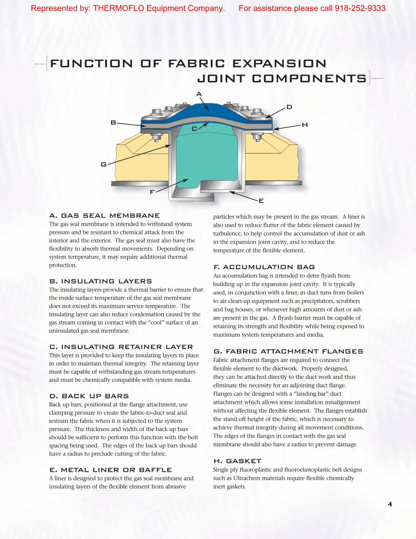
FUNCTION OF FABRIC EXPANSIONJOINT COMPONENTS
A. GAS SEAL MEMBRANEThe gas seal membrane is intended to withstand systempressure and be resistant to chemical attack from theinterior and the exterior. The gas seal must also have theflexibility to absorb thermal movements. Depending onsystem temperature, it may require additional thermalprotection.
B. INSULATING LAYERSThe insulating layers provide a thermal barrier to ensure thatthe inside surface temperature of the gas seal membranedoes not exceed its maximum service temperature. Theinsulating layer can also reduce condensation caused by thegas stream coming in contact with the “cool” surface of anuninsulated gas seal membrane.
C. INSULATING RETAINER LAYERThis layer is provided to keep the insulating layers in placein order to maintain thermal integrity. The retaining layermust be capable of withstanding gas stream temperaturesand must be chemically compatible with system media.
D. BACK UP BARSBack up bars, positioned at the flange attachment, useclamping pressure to create the fabric-to-duct seal andrestrain the fabric when it is subjected to the systempressure. The thickness and width of the back up barsshould be sufficient to perform this function with the boltspacing being used. The edges of the back up bars shouldhave a radius to preclude cutting of the fabric.
E. METAL LINER OR BAFFLEA liner is designed to protect the gas seal membrane andinsulating layers of the flexible element from abrasive
particles which may be present in the gas stream. A liner isalso used to reduce flutter of the fabric element caused byturbulence, to help control the accumulation of dust or ashin the expansion joint cavity, and to reduce thetemperature of the flexible element.
F. ACCUMULATION BAGAn accumulation bag is intended to deter flyash frombuilding up in the expansion joint cavity. It is typicallyused, in conjunction with a liner, in duct runs from boilersto air clean-up equipment such as precipitators, scrubbersand bag houses, or whenever high amounts of dust or ashare present in the gas. A flyash barrier must be capable ofretaining its strength and flexibility while being exposed tomaximum system temperatures and media.
G. FABRIC ATTACHMENT FLANGESFabric attachment flanges are required to connect theflexible element to the ductwork. Properly designed, they can be attached directly to the duct work and thuseliminate the necessity for an adjoining duct flange.Flanges can be designed with a “landing bar” ductattachment which allows some installation misalignmentwithout affecting the flexible element. The flanges establishthe stand off height of the fabric, which is necessary toachieve thermal integrity during all movement conditions.The edges of the flanges in contact with the gas sealmembrane should also have a radius to prevent damage.
H. GASKETSingle ply fluoroplastic and fluoroelastoplastic belt designssuch as Ultrachem materials require flexible chemicallyinert gaskets.
-––[]–-–
A
B
G
F
C
D
H
E
Represented by: THERMOFLO Equipment Company. For assistance please call 918-252-9333

5
PRODUCTS, MARKETS & APPLICATIONS
-––[]–-–
FOSSIL FIRED POWER MARKET APPLICATIONS
Applications rangefrom the FD fan to theprimary air, temperingair, coal mill, boilerflue duct joints,economizer, air heater,precipitator, baghouse,fabric filter, ID fan,scrubber, absorber,reheater and stackexpansion joints.
ENGINEERING SERVICESSenior Flexonics Pathwaysupports its fabricexpansion joint productswith experienced fieldengineers, On-Site serviceinstallation, repairservices, and CADsupported applicationengineers to help yousolve your expansionjoint problems.
MANUFACTURING CAPABILITYWe have theunique ability toreact quickly tosupport youroutage needs forfabric expansionjoints. SeniorFlexonicsPathway can
produce round, rectangular and custom shapes for everyapplication. We are well known worldwide for our“Round the Clock” Service.
ULTRACHEM AND FLEXON MATERIALS
Senior FlexonicsPathway is thecompany that firstdeveloped the use offluoropolymer (PTFE)materials in expansionjoint systems.Specifically designedfor a variety of wet and
dry corrosive applications, these materials will exceedyour system requirements.
GAS TURBINE EXHAUST APPLICATIONSOur fabric expansion joints are currently in service inpeaking plants, on shipboard power systems, on co-generation turbines, natural gas pipeline pump stationsand a variety of heat recovery.
Represented by: THERMOFLO Equipment Company. For assistance please call 918-252-9333
6
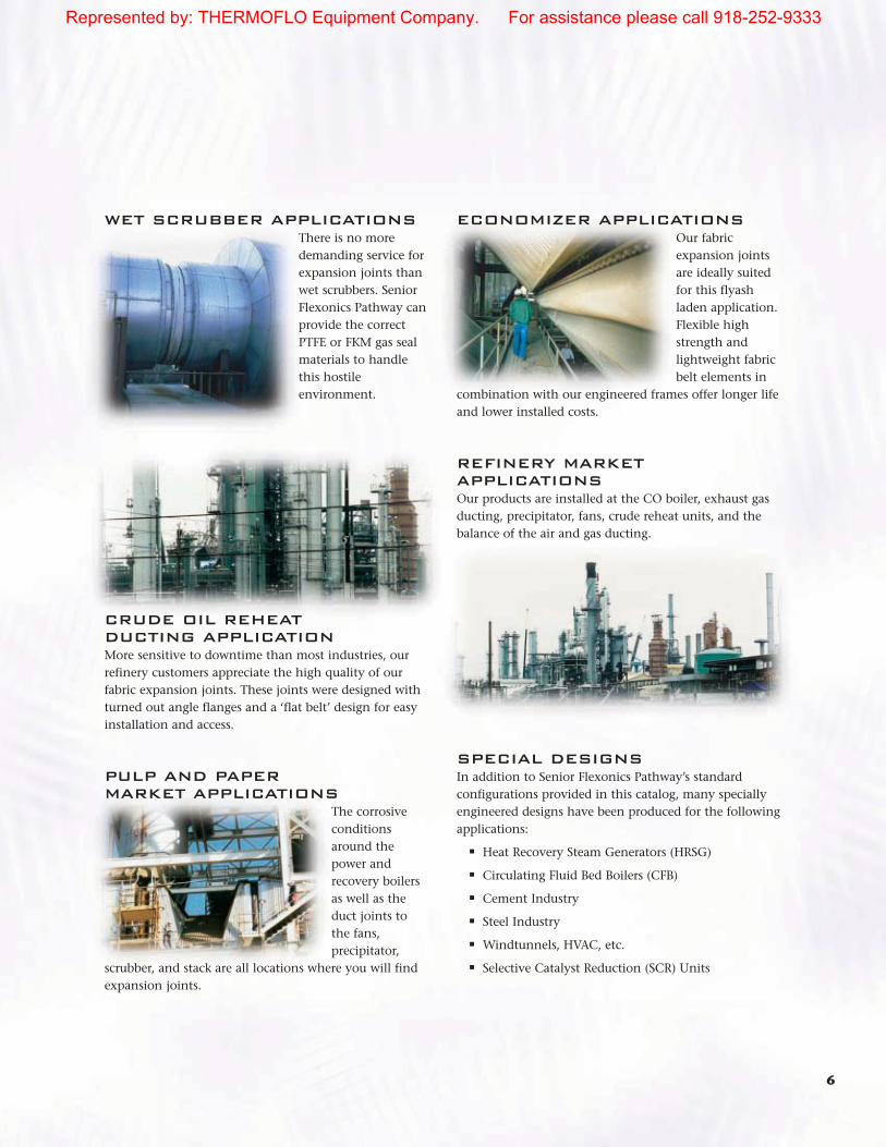
WET SCRUBBER APPLICATIONSThere is no moredemanding service forexpansion joints thanwet scrubbers. SeniorFlexonics Pathway canprovide the correctPTFE or FKM gas sealmaterials to handlethis hostileenvironment.
CRUDE OIL REHEAT DUCTING APPLICATIONMore sensitive to downtime than most industries, ourrefinery customers appreciate the high quality of ourfabric expansion joints. These joints were designed withturned out angle flanges and a ‘flat belt’ design for easyinstallation and access.
PULP AND PAPER MARKET APPLICATIONS
The corrosiveconditionsaround thepower andrecovery boilersas well as theduct joints to the fans,precipitator,
scrubber, and stack are all locations where you will findexpansion joints.
ECONOMIZER APPLICATIONSOur fabricexpansion jointsare ideally suitedfor this flyashladen application.Flexible highstrength andlightweight fabricbelt elements in
combination with our engineered frames offer longer lifeand lower installed costs.
REFINERY MARKETAPPLICATIONSOur products are installed at the CO boiler, exhaust gasducting, precipitator, fans, crude reheat units, and thebalance of the air and gas ducting.
SPECIAL DESIGNSIn addition to Senior Flexonics Pathway’s standardconfigurations provided in this catalog, many speciallyengineered designs have been produced for the followingapplications:
■ Heat Recovery Steam Generators (HRSG)
■ Circulating Fluid Bed Boilers (CFB)
■ Cement Industry
■ Steel Industry
■ Windtunnels, HVAC, etc.
■ Selective Catalyst Reduction (SCR) Units
Represented by: THERMOFLO Equipment Company. For assistance please call 918-252-9333
7
MOVEMENTCAPABILITIES
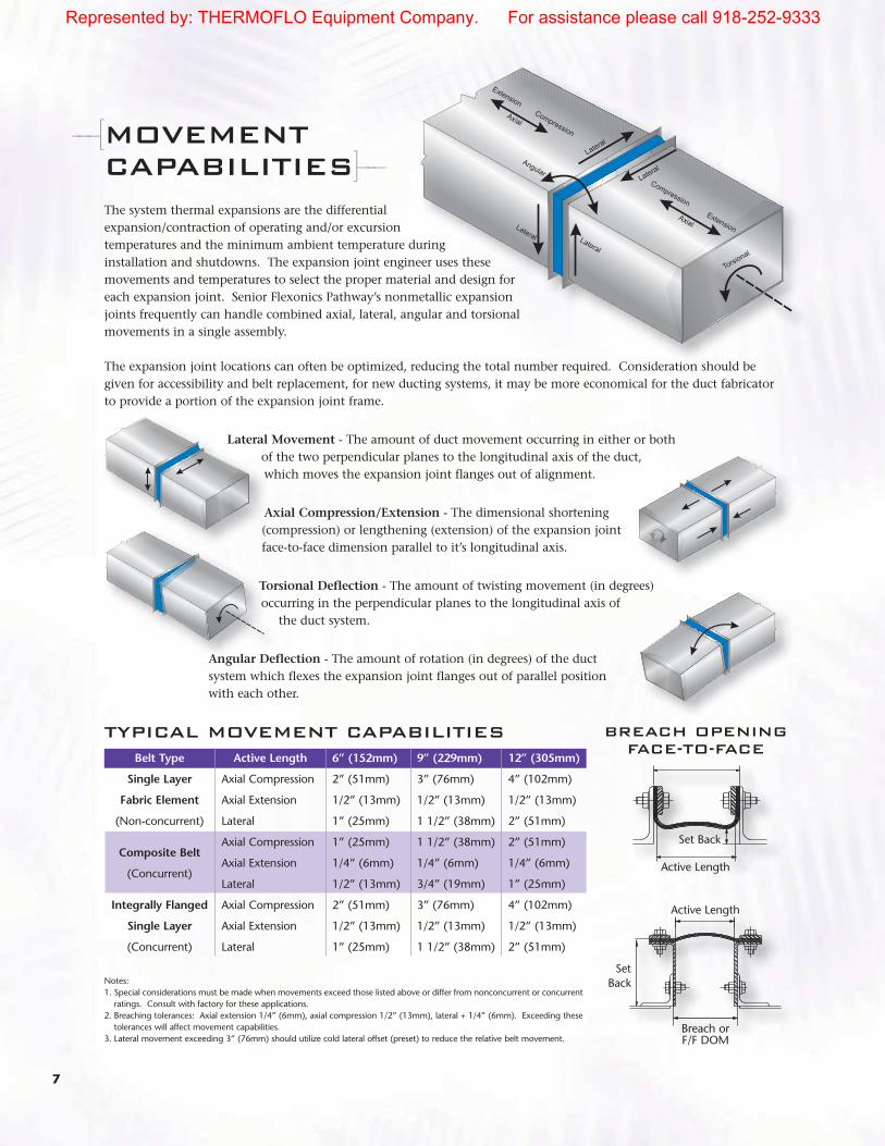
The system thermal expansions are the differentialexpansion/contraction of operating and/or excursiontemperatures and the minimum ambient temperature duringinstallation and shutdowns. The expansion joint engineer uses thesemovements and temperatures to select the proper material and design foreach expansion joint. Senior Flexonics Pathway’s nonmetallic expansionjoints frequently can handle combined axial, lateral, angular and torsionalmovements in a single assembly.
The expansion joint locations can often be optimized, reducing the total number required. Consideration should begiven for accessibility and belt replacement, for new ducting systems, it may be more economical for the duct fabricatorto provide a portion of the expansion joint frame.
Lateral Movement - The amount of duct movement occurring in either or bothof the two perpendicular planes to the longitudinal axis of the duct,which moves the expansion joint flanges out of alignment.
Axial Compression/Extension - The dimensional shortening(compression) or lengthening (extension) of the expansion joint face-to-face dimension parallel to it’s longitudinal axis.
Torsional Deflection - The amount of twisting movement (in degrees) occurring in the perpendicular planes to the longitudinal axis of
the duct system.
Angular Deflection - The amount of rotation (in degrees) of the ductsystem which flexes the expansion joint flanges out of parallel positionwith each other.
-––[
Notes:1. Special considerations must be made when movements exceed those listed above or differ from nonconcurrent or concurrent
ratings. Consult with factory for these applications.2. Breaching tolerances: Axial extension 1/4” (6mm), axial compression 1/2” (13mm), lateral + 1/4” (6mm). Exceeding these
tolerances will affect movement capabilities.3. Lateral movement exceeding 3” (76mm) should utilize cold lateral offset (preset) to reduce the relative belt movement.
Belt Type
Single Layer
Fabric Element
(Non-concurrent)
Composite Belt
(Concurrent)
Integrally Flanged
Single Layer
(Concurrent)
TYPICAL MOVEMENT CAPABILITIES
Active Length
Axial Compression
Axial Extension
Lateral
Axial Compression
Axial Extension
Lateral
Axial Compression
Axial Extension
Lateral
6” (152mm)
2” (51mm)
1/2” (13mm)
1” (25mm)
1” (25mm)
1/4” (6mm)
1/2” (13mm)
2” (51mm)
1/2” (13mm)
1” (25mm)
9” (229mm)
3” (76mm)
1/2” (13mm)
1 1/2” (38mm)
1 1/2” (38mm)
1/4” (6mm)
3/4” (19mm)
3” (76mm)
1/2” (13mm)
1 1/2” (38mm)
12” (305mm)
4” (102mm)
1/2” (13mm)
2” (51mm)
2” (51mm)
1/4” (6mm)
1” (25mm)
4” (102mm)
1/2” (13mm)
2” (51mm)
]–-–
Active Length
Active Length
SetBack
Set Back
BREACH OPENING FACE-TO-FACE
Breach orF/F DOM
Represented by: THERMOFLO Equipment Company. For assistance please call 918-252-9333

8
SPECIAL APPLICATION CHIMNEY GAS SEALS
THE PROBLEMNumerous fossil-fueled utility chimneys built between the years 1950 and 1970 used a rope packing design as a gas seal between adjacent sections of brick liners. Should the rope packing leak, flue gas may attack the less resistant concrete chimneys causing leakage and chimney deterioration.
DESIGN SOLUTIONA fabric expansion joint has been designed to eliminate the need for the original seals as well as provide for improved inspection and maintenance. Features of the design include:
■ Lower installed cost due to lighter weight materials.■ Gas seal membrane for long life■ Easily repairable by heat sealing methods■ Easily accessible■ Unique frame design for easy access■ Chimney air seal
THE PROBLEMPenetration of flue gas ducts through the chimney liner and outer shell require an air tight sealfor a pressurized chimney annulus. Leaky seals allow the flue gases to enter the annulus andattack the outer concrete structure shell.
DESIGN SOLUTIONA dual picture frame attached to the duct and the liner(or shell) utilizing UltraChem™ Gas Seal Membrane isinstalled to span between the two frames creating theseal. Benefits of the design are:
■ Easily repairable by heat seal methods
■ Lower installed cost due to lighter weight materials
■ Easily accessible for inspection or repair
-––[]–-–
Represented by: THERMOFLO Equipment Company. For assistance please call 918-252-9333

9
OPERATIONAL & DESIGNCONSIDERATIONS
The following background information on the plant andapplication can have significant influence to the designlife of the expansion joint.
■ Plant type ■ Location of expansion■ Environmental conditions■ Base or peak load plant ■ Relevant history of existing and adjacent equipment
FLOW MEDIAIn defining system media, the designer should specify the type of fuel, sulfur content, and any additives,cleaning agents or catalysts, which may be used in thesystem. Ph in the vicinity of the expansion joint shouldbe specified, if known, especially if the media isextremely acidic or caustic.
The probability of condensation should be determinedby comparing dew point and normal operatingtemperatures. Even in systems which normally operatequite hot, shutdowns and startups may producecondensation resulting in excessive corrosion. Thiscondition can also occur on the outside of the steelworkand should be considered.
Abrasive components of the media such as flyash shouldbe identified. Flyash buildup within a flue gas ductshould be estimated, and the dead weight calculated todetermine the maximum load on an expansion jointelement. Plant operating procedures such as ductcleaning (wash-down or vacuuming) are also consideredin the design.
TEMPERATURETemperatures affect the selection of fabric expansionjoint materials. The following temperatures for thesystem should be provided to the engineer.
■ Normal operating temperature■ Maximum continuous operating temperature■ Design temperature■ Excursion temperatures and duration■ Ambient temperatures (the lowest, highest
and average)■ Dew point temperatures
Caution: Specifying a “design temperature” whichincludes excessive safety factors may actually be
detrimental to the design of the flexible element andshould be avoided.
PRESSURE & EXPANSION JOINT LEAKAGE Fabric expansion joints are typically designed for lowpressure duct systems with maximum rating at +5 psigfor elastomeric and +3 psig for fluoroplastic andfluoroelastoplastic belts.
Fabric expansion joints are designed to be as leak tight as practical. When an unusual amount of liquid ispresent within the ducting, or leakage requirements arespecified, special caulking or gasket materials can be used when attaching the fabric element to attain thedesired results. In industrial applications, minor leakage,detectable by soap bubble solution, is consideredacceptable.
When replacing a fabric element, leakage through boltholes is minimized if holes are aligned and punched in the field as opposed to prepunching the holes at the factory. Backup bar bolts should be tightened to 35 to 45 ft. lbs. (45-61 Nm) to ensure optimum clamping pressure.
MOVEMENTSVarious movements resulting from thermal expansion of the breeching, both Maximum Continuous SystemOperating Temperature (MCSOT) and excursiontemperatures should be specified. Contractions of thebreeching due to cold winter shutdowns, mechanicallyinduced movements such as fan and equipmentvibrations, and structural deflections due to wind loadsand seismic events must also be specified.
Movements in various directions should be analyzed todetermine if they occur simultaneously or if they canoccur individually without a corresponding deflection inanother direction. The designer to make certain that theexpansion joint design is capable of absorbing acombination of the total maximum movements shouldspecify maximum installation misalignment.
SYSTEM GEOMETRY/INSTALLATIONThe geometry of the expansion joint system, includingduct size, orientation, material and attachments all havean effect on the selection of expansion joint frame
-––[]–-–
Represented by: THERMOFLO Equipment Company. For assistance please call 918-252-9333
10
configuration. The installation of an expansion joint canbe performed either internally or externally. Specificframes are designed for each application depending onpreferences or accessibility.
EXTERNAL ENVIRONMENT Correct operation of high temperature expansion jointsrequires that a portion of the system heat be dissipated tothe external environment. Abnormally hot ambientconditions or an adjacent heat source, reflective surface,or duct insulation may create temperatures that exceedthe limits of the gas seal membrane and should beconsidered when designing the system.
An external cover may be desirable to help protectagainst failing objects or the accumulation of combustiblematerials such as coal or saw dust. Covers should bedesigned by the expansion joint manufacturer to ensurethat proper air circulation requirements are satisfied.
EXPANSION JOINT FLUTTERThe inherent flexibility of expansion joints can causefatigue problems as a result of physical fluctuationsknown as flutter. Flutter is a result of either flow induced
or operating pressure oscillations. Both conditions can
cause a premature failure and must be identified in the
quotation/evaluation stage. This condition is commonly
found adjacent to turning vanes, ID fan and stacks. This
pressure oscillation typically exists in ductwork locations
where the static pressure is very low ±1 to ±2” w.c (±25 to
±50 mm H2O).
INSTALLATIONCONSIDERATIONSThe system designer must consider all installation
requirements such as mating duct flanges, adjacent
ducting equipment, insulation, painting/ finishing, field
assembly, erection and necessary qualified supervision.
RESPONSIBILITYThe system designer must evaluate whether the lines of
responsibility are clear between the ducting supplier,
erector, and the expansion joint supplier, and if they will
result in a system that meets specification requirements
at an optimum overall cost. It is usually in the best
interests of the end user to specify and/or order the
expansion joints themselves.
Represented by: THERMOFLO Equipment Company. For assistance please call 918-252-9333

CAVITY PILLOW STYLESThe Senior Flexonics Pathway cavity pillows serve three purposes, retarding theintrusion of particulate, thermal protection, and resistance to pressure pulsation.Our pillows are fabricated from selected insulation materials and wrapped with ahigh temperature fabric, designed for the operating conditions. Standard pillows areprovided with “ears” or tabs that fasten under the belt and backup bars to hold the
pillow in place. The ears are designed to provide a memory to thepillow such that it will return to an “as installed” uncompressedstate after plant cool down, during outages.
CAVITY ACCUMULATION PILLOW (CAP)A cavity created between the structural steel frame/flanges and thegas seal (fabric expansion joint) is designed to provide a standoffbetween the fabric element and the flue gas. This cavity can fillwith particulate falling out of the flue gas. If these deposits areallowed to buildup the expansion joint will fail to operate properlyand could become damaged. Senior Flexonics Pathwayrecommends the use of an accumulation pillow designed to occupythis “dead space”, preventing the deposits from entering and fillingthis cavity. The cavity pillow in conjunction with a flow liner willprevent the accumulation of particulate/fly ash. Manymaintenance managers view this option as a low cost insurancepolicy that extends the service life of the expansion joint.
HIGH TEMPERATURE CAVITY INSULATION PILLOWS (CIP)Cavity Insulation Pillow (CIP) - A style CIP provides additionalthermal protection to the belting material for high temperatureapplications.
11
CAVITY PILLOW-––[ ]–-–
Style - 1
Style - 3
Style - 2
FLOW LINERSFlow liners (baffles) are metal shields designed to provide protection for the fabric element and/orcavity pillow from direct impingement of particulate or particulate accumulation. A liner is alsoused to reduce flutter of the fabric element caused by turbulence, to help control theaccumulation of dust or ash in the expansion joint cavity, and to reduce the temperature of theflexible element. Flow liners can be supplied on a variety of profiles (straight, airfoil, semi-airfoilor telescoping) and materials. (Standard profile and material are straight 10 GA. A569 C.S.). Flowliners fall into the following categories.
■ Integral liners are pre-manufactured parts of the expansion joint frame as on SR2700 andSR2750 series frames.
■ Bolt-in liners are primarily used on integrally flanged style expansion joints as on our U1000series, between the belt or expansion joint flange and the mating duct flange. Gaskets arerequired on metal-to-metal and/or Teflon®-to-metal connections.
■ Weld-in liners spanning the breach opening can be either welded in the field to the ductinterior or can be supplied welded in factory to the expansion joint frame.
Typical cavity pillow
construction consisting
of layers of insulation
encased in a protective
high temp sleeve.
Integral Liner
Weld-in Liner
Bolt-in Liner
-––[ ]–-–
Represented by: THERMOFLO Equipment Company. For assistance please call 918-252-9333

12
OPTIONS & ACCESSORIES
BRAIDED HOSE SEAL (BH)Flexible stainless steel braided hose with enclosed ceramic insulation is oftenspecified for expansion joints in areas of high particulate loading. The hose issecured between the flow liners to prevent particulate from entering theexpansion joint cavity. This accessory along with a cavity pillow workswell in cement plants.
TADPOLE GASKET TAPE (TG)When using integral flange-type expansion joints in duct systems withpositive pressure operating conditions, Senior Flexonics Pathwayrecommends the use of tadpole gasketing between the flexible elementflange and backup bars (as illustrated). This prevents the heads of the
erection bolts from abrading the outside cover of the flexible element.This option also protects both flat and integrally flanged belts during large
lateral or compression movements.
FLOW DEFLECTOR (FD)In some expansion joint installations, an angle flow deflector is added to the design toincrease the service life of the joint. A flow deflector is used to prevent moisture andparticulate from sliding down vertical duct walls and being trapped in the expansionjoint cavity by the flow liner.
FRAME STYLES
Senior Flexonics Pathway provides numerous frame designs for various applications. The integrally flanged U-beltdesign has a very economical initial capital cost. The flat belt frame design has a lower replacement belt cost andexisting hardware can be reused. The following is a sample of several standard arrangements.
SR2400Design applications where the ductwork flanges are present and a complete frameassembly is preferred. This style works well for high temperature applications.
■ Complete drop-in assembly■ Prefabricated standard frames reduce cost■ Belting hardware accessible from outside■ Best choice when adjacent structures or equipment cannot permit liner
protrusion beyond attachment flange.■ Accepts shop welded flow liner■ Readily accepts eared pillow design■ Used to fill large breech openings■ Accommodates large lateral movements■ Provides proper setback for belt protection
-––[ ]–-–
-––[ ]–-–
TP
FD
Senior Flexonics Pathway expansion joints are furnished assembled or unassembled.
SR2400
Represented by: THERMOFLO Equipment Company. For assistance please call 918-252-9333

13
SR2500Complete drop-in assembly design which works well with low to moderatetemperature applications with low levels of particulate accumulation.
■ Economic frame using standard angle sizes■ Accessibility to bolting hardware■ Accepts shop welded flow liner■ Designed for internal (SR2550) or external belt replacement (SR2500)■ Used frequently with fan applications■ Studs or tack welded nuts are optional on belt flange
SR2600Similar to the SR2500 style and is used where additional standoff is necessary orpreferred. This design works well in low to moderate temperature applications withlow levels of particulate accumulation.
■ Economic frame using standard angle sizes■ Fabric wrap design used to retrofit over existing metal expansion joints
(possible on-line installation)■ Complete assembly drop-in design■ Designed for internal (SR2650) or external belt replacement (SR2500)■ Used frequently with fan applications■ Accepts shop welded flow liner■ Studs or tack welded nuts are optional on belt flange
SR2700Used for low-to-high temperature applications with a cavity pillow, where high levelsof particulate are present.
■ Accommodates both flanged and non-flanged ductwork■ “Z” style with integral telescoping flow liners■ Reduces particulate accumulation in frame cavity■ Provides protection for belts and pillows■ Complete accessibility to bolting hardware■ Accepts eared pillow design■ Accommodates large lateral movements■ Tack welded nuts are optional■ Provides proper setback for belt protection
SR2750Similar to SR2700 with the exception of a single integral flow liner. This designworks well with lower particulate levels or vertical duct applications.
■ Accommodates both flanged and non-flanged ductwork■ “Z” style integral upstream flow liner■ Provides protection for belts and pillows ■ Complete accessibility to bolting hardware■ Accommodates large lateral movements■ Tack welded nuts are optional■ Provides proper setback for belt protection
Senior Flexonics Pathway expansion joints are furnished assembled or unassembled.
SR2500
SR2600
SR2550
SR2700
SR2750
SR2650
Represented by: THERMOFLO Equipment Company. For assistance please call 918-252-9333

14
SR2800This style frame is well suited for installation with field assembly over existingexpansion joints, and is utilized for all temperature ratings.
■ Economic frame utilizing standard prefabricated angle iron■ Either welded or bolted frame can be utilized ■ Fabric wrap design can be used to retrofit over existing metal expansion
joints (possible on-line installation)■ Accepts eared pillow design■ Facilitates field assembly and fit-up■ Tack welded nuts are optional■ Provides proper setback for belt protection
SR2900Best utilized where flanges are not present and field assembly is required or preferred.
■ Fabric wrap design used over existing metal expansion joints (possible on-line installation)
■ Provides additional stiffener reinforcement to existing ductwork■ Utilizes standard structural steel channels for economical design■ Flanges act as duct stiffiners
U1000The standard integrally flanged U-belt design is used for low to moderate temperaturesapplications where duct flanges are present and particulate loading is minimal
■ Lowest initial cost due to reduced metal frame and fasteners cost■ Molded corners provided for rectangular ductwork■ Accommodates flanged ducting or equipment and utilized frequently for
fan applications■ Minimal shipping costs■ Standard 3” (75mm) high flange design
SLEEVESSleeves are primarily used for vibration in H.V.A.C. applications with minimalpressures.
■ Least expensive design■ Supplied endless or open ended for field-wrap of pipe penetration applications■ Supplied with worm gear band clamps■ For vibration applications■ Provided with gaskets for Teflon® belt material
Senior Flexonics Pathway expansion joints are furnished assembled or unassembled.
SR2800
SR2900
U1000
Sleeves
Represented by: THERMOFLO Equipment Company. For assistance please call 918-252-9333
15
INSTALLATION CONSIDERATIONS
MATING DUCT FLANGESMating duct flanges affect expansion joint design. Senior Flexonics Pathway FrameSystems SR2700, SR2800 and SR2900 are designed to completely eliminate matingflanges on the duct work. Other frame systems are designed to be welded toexisting flanges, thereby decreasing installation time and corrosion problemsassociated with bolted designs. The design of duct flanges should be coordinatedwith the expansion joint manufacturer.
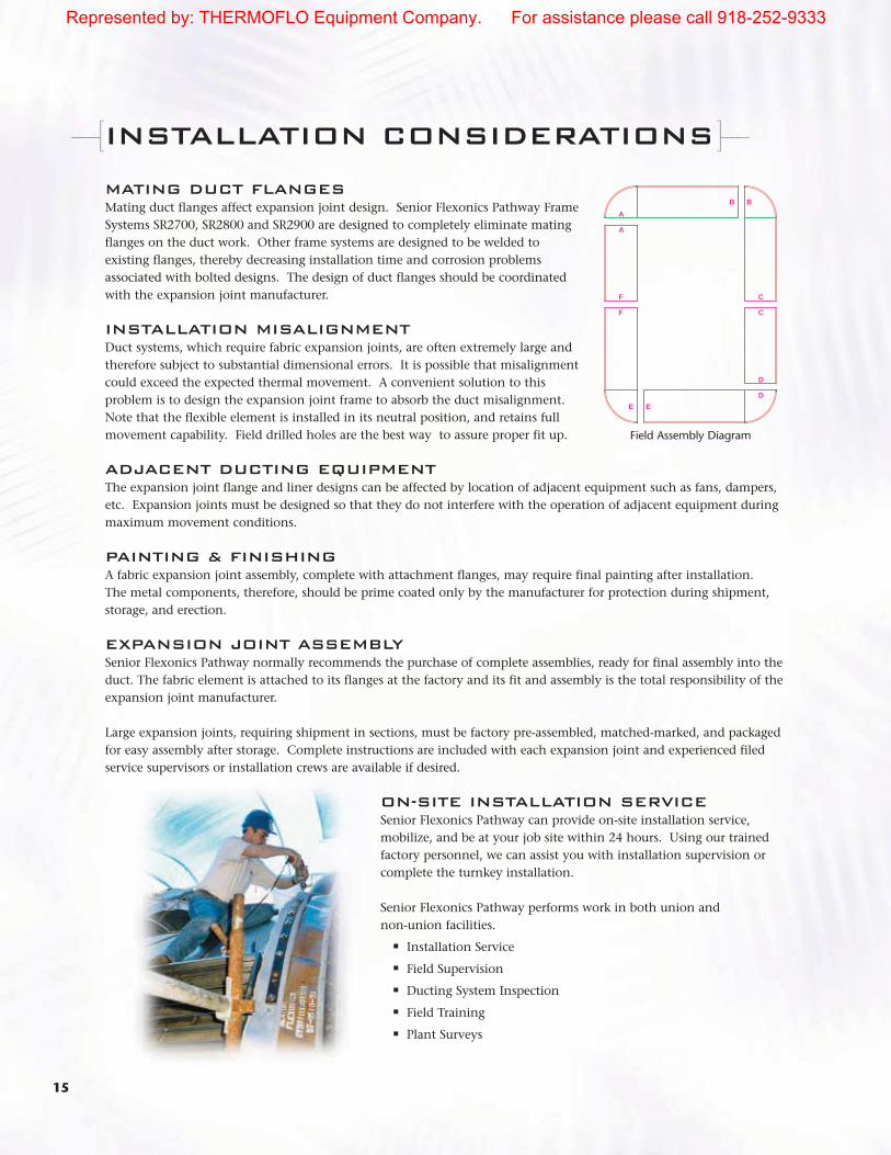
INSTALLATION MISALIGNMENTDuct systems, which require fabric expansion joints, are often extremely large andtherefore subject to substantial dimensional errors. It is possible that misalignmentcould exceed the expected thermal movement. A convenient solution to thisproblem is to design the expansion joint frame to absorb the duct misalignment.Note that the flexible element is installed in its neutral position, and retains fullmovement capability. Field drilled holes are the best way to assure proper fit up.
ADJACENT DUCTING EQUIPMENTThe expansion joint flange and liner designs can be affected by location of adjacent equipment such as fans, dampers,etc. Expansion joints must be designed so that they do not interfere with the operation of adjacent equipment duringmaximum movement conditions.
PAINTING & FINISHINGA fabric expansion joint assembly, complete with attachment flanges, may require final painting after installation. The metal components, therefore, should be prime coated only by the manufacturer for protection during shipment,storage, and erection.
EXPANSION JOINT ASSEMBLYSenior Flexonics Pathway normally recommends the purchase of complete assemblies, ready for final assembly into theduct. The fabric element is attached to its flanges at the factory and its fit and assembly is the total responsibility of theexpansion joint manufacturer.
Large expansion joints, requiring shipment in sections, must be factory pre-assembled, matched-marked, and packagedfor easy assembly after storage. Complete instructions are included with each expansion joint and experienced filedservice supervisors or installation crews are available if desired.
ON-SITE INSTALLATION SERVICESenior Flexonics Pathway can provide on-site installation service,mobilize, and be at your job site within 24 hours. Using our trainedfactory personnel, we can assist you with installation supervision orcomplete the turnkey installation.
Senior Flexonics Pathway performs work in both union and non-union facilities.
■ Installation Service
■ Field Supervision
■ Ducting System Inspection
■ Field Training
■ Plant Surveys
-––[ ]–-–
A
F C
A
F C
B B
EE
D
D
Field Assembly Diagram
Represented by: THERMOFLO Equipment Company. For assistance please call 918-252-9333
16
SPLICING AND REPAIRABILITY -––[ ]–-–
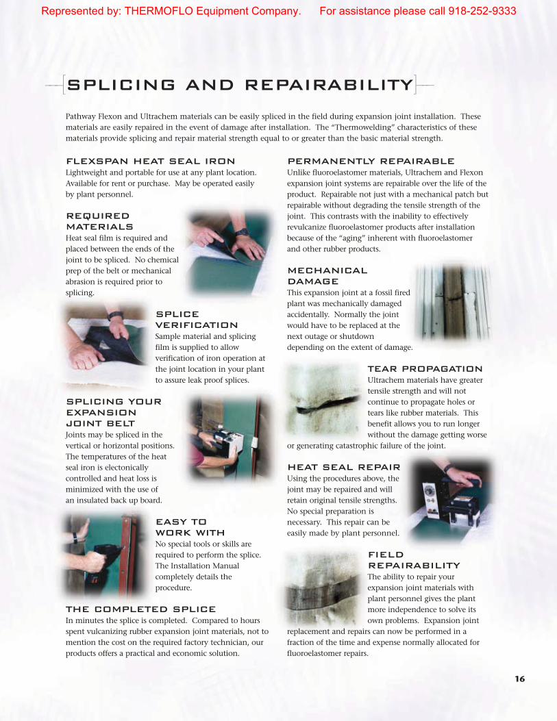
FLEXSPAN HEAT SEAL IRONLightweight and portable for use at any plant location.Available for rent or purchase. May be operated easily by plant personnel.
REQUIREDMATERIALSHeat seal film is required andplaced between the ends of thejoint to be spliced. No chemicalprep of the belt or mechanicalabrasion is required prior tosplicing.
SPLICEVERIFICATIONSample material and splicingfilm is supplied to allowverification of iron operation atthe joint location in your plantto assure leak proof splices.
SPLICING YOUR EXPANSION JOINT BELTJoints may be spliced in thevertical or horizontal positions.The temperatures of the heatseal iron is electonicallycontrolled and heat loss isminimized with the use of an insulated back up board.
EASY TO WORK WITHNo special tools or skills arerequired to perform the splice.The Installation Manualcompletely details theprocedure.
THE COMPLETED SPLICEIn minutes the splice is completed. Compared to hoursspent vulcanizing rubber expansion joint materials, not tomention the cost on the required factory technician, ourproducts offers a practical and economic solution.
PERMANENTLY REPAIRABLEUnlike fluoroelastomer materials, Ultrachem and Flexonexpansion joint systems are repairable over the life of theproduct. Repairable not just with a mechanical patch butrepairable without degrading the tensile strength of thejoint. This contrasts with the inability to effectivelyrevulcanize fluoroelastomer products after installationbecause of the “aging” inherent with fluoroelastomer and other rubber products.
MECHANICALDAMAGEThis expansion joint at a fossil firedplant was mechanically damagedaccidentally. Normally the jointwould have to be replaced at thenext outage or shutdowndepending on the extent of damage.
TEAR PROPAGATIONUltrachem materials have greatertensile strength and will notcontinue to propagate holes ortears like rubber materials. Thisbenefit allows you to run longerwithout the damage getting worse
or generating catastrophic failure of the joint.
HEAT SEAL REPAIRUsing the procedures above, thejoint may be repaired and willretain original tensile strengths.No special preparation isnecessary. This repair can beeasily made by plant personnel.
FIELDREPAIRABILITYThe ability to repair yourexpansion joint materials withplant personnel gives the plantmore independence to solve itsown problems. Expansion joint
replacement and repairs can now be performed in afraction of the time and expense normally allocated forfluoroelastomer repairs.
Pathway Flexon and Ultrachem materials can be easily spliced in the field during expansion joint installation. Thesematerials are easily repaired in the event of damage after installation. The “Thermowelding” characteristics of thesematerials provide splicing and repair material strength equal to or greater than the basic material strength.
Represented by: THERMOFLO Equipment Company. For assistance please call 918-252-9333

17
FLEXON PRODUCT LINE
Senior Flexonics Pathway manufactures a variety of composite belt configurations to meet thevaried needs of all our customers. Shown for illustration purposes is one of the premium gradebelt constructions for each rated continuous operating temperatures.
-––[ ]–-–
4 mil (0.1 mm) cast PTFE corrosion resistant film
Multilayer reinforcedcontinuous filamentfiberglass yarn (Fill)
Wrapped to maximizeflexibility and tensile strength
Bundled and twisted for flexibility
Woven to provideextended life matrix
FLUORINATED ELASTOPLASTICS Fluoroelastoplastics combine the corrosion resistance of a fluoroplastic with the flexibility of a fluoroelastomer through the addition of FKM to the PTFE compound. Fluoroelastoplasticmaterials have been used successfully in over 10,000 expansion joints worldwide, providingexceptional performance even in the severe chemical environments found in flue gasdesulfurization plants (FGD), pulp and paper (recovery boilers), refuse derived fuels (RDF) and smelters.
DARLYN® PRODUCT LINESenior Flexonics Pathway is an authorized fabricator of expansion joints utilizing ChemfabCorporation’s DARLYN fabrics. These products were first introduced in 1983. The DARLYN line of materials are fluorinatedelastoplastic alloys. Because of their thermal and chemicalcapabilities, fluoroelastoplastic fiberglass reinforced, PTFE-coated and laminated belting materialsare being used extensively in expansion joint designs for all types of systems.
Represented by: THERMOFLO Equipment Company. For assistance please call 918-252-9333

18
PATENTED PTFE/FKM ALLOY PROVIDES ADDITIONAL FLEXIBILITY
Perfluoroplastic, due to its crystalline nature, isinherently stiff which reduces the long term flexendurance and life of PTFE fabric expansion joints.To overcome this shortcoming, fluoroelastomer(Viton®/Fluorel®) is blended into a patented alloy which bathes the coated fiberglass matrix significantlyincreasing the flexibility, tear resistance, tensile and shearstrength of DARLYN fabricated belts. This means longerin-service life.
DARLYN can be easily identified by its lack of stiffness.The uniformly distributed alloy coating is morecompliant than PTFE, filling the voids and impregnatingthe woven structure. This pliable matrix maintainsconsistent physical and chemical properties over a widerange of temperatures and corrosive conditionsexperienced in flue gas ductwork.
CONSISTENT COATING PROCESSThe DARLYN series of products are coated and cured over a dozen times in the patented process.The multilayer alloy coating of PTFE and FKM completely surrounds the fiberglass foundation,and then is multi-coated with PTFE. This unique procedure is a characteristic of the detailedquality and consistency which guarantees the longevity of the DARLYN products.
DARLYN material is manufactured with 100% defect free, continuous, twisted multiple filamentfiberglass. This means that for the entire length of your DARLYN belting material the strands areuncut, homogeneous and guaranteed the strongest fiberglass fibers possible. Numerous strandsare than grouped and twisted together maximizing the flex, tensile, shear and tear characteristicsof thousands of filaments. These glass yarns are then bathed with a protectant PTFE coating toresist self-abrasion and friction during flexing, and chemical attack preventing acid from wickingin service, which destroys conventional woven glass.
-––[]–-–
Represented by: THERMOFLO Equipment Company. For assistance please call 918-252-9333

19
DARLYN 1100 CB & ULTRACHEM CB or Chemical Barrier was developed for superior corrosion resistance. A multilayer PTFE castfilm is thermally and chemically welded to DARLYN 1100 and ULTRACHEM assuring an evengreater protection from corrosion due to exposure in the most extreme conditions. Thisisotropic film (identical physical properties in all directions) is built up through multipleoperations assuring a uniform thickness, nonporous, chemically inert barrier. Further, whencombined with the DARLYN and ULTRACHEM isotropic fabric, the result is a uniform membranewhich can flex without stress concentrations, distributing the load equally throughout the belt.
HIGH TEMPERATURE APPLICATIONS■ Superior strength retention, even after repeated flexing.■ Fast, easy field splicing■ Outstanding corrosion resistance■ Less than 1/4 the weight of 100% fluoroelastomer fabrics, resulting in lower installed costs
FLEXON-700 A composite belt designed to provide continuous reliable service at 700°F (371°C). A tightly woven fiberglassinsulation is thermally bonded to theFLEXON material. This composite designprovides insulating properties at elevatedtemperatures and prevents separation of the insulation.
FLEXON-1000 A composite beltdesigned to provide continuous reliableservice at 1000°F (538°C). A non-wovenfiberglass needle-mat insulation is bondedto the ULTRACHEM material and encasedin aluminized coated fiberglass cloth.
60 oz (0.64 g/cm3)tightly woven fiberglassmat insulation laminatedto the gas seal
4 mil PTFE filmlaminated to ULTRACHEM cover
ULTRACHEM fluoroplasticcoated fiberglass fabric
5/8” (16 mm) thicknonwoven fiberglassinsulation laminated to the gas seal
ULTRACHEM Fluoroplastic coatedfiberglass fabric with 4 mil (0.1 mm)PTFE film laminated to gas side
Represented by: THERMOFLO Equipment Company. For assistance please call 918-252-9333

20
FLEXON-1200 A composite beltdesigned to provide continuous service at 1200°F (649°C), by theaddition of a 1/2” (13 mm) of ceramicmat insulation to the FLEXON 1000.Inconel® wire inserted silica cloth isused as the encasement to replacefiberglass in applications above 1000°F (538°C).
FLEXON-1500 A composite beltdesigned to provide continuousservice at elevated continuoustemperatures to 1500°F (816°C).
1/2” (13 mm)ceramic matinsulation Inconel wire reinforced
silica/ceramic fabric encasement
1” (25 mm) thick ceramic mat insulation
Inconel wire reinforcedsilica/ceramic fabricreinforcement encasement
5/8” (16 mm) thicknonwoven fiberglassinsulation laminated to the gas seal
5/8” (16 mm) thicknonwoven fiberglassinsulation laminated to the gas seal
ULTRACHEM Fluoroplastic coatedfiberglass fabric with 4 mil (0.1 mm)PTFE film laminated to gas side
ULTRACHEM Fluoroplastic coatedfiberglass fabric with 4 mil (0.1 mm)PTFE film laminated to gas side
Note: Designs are available to 2000°F (1090°C).
Represented by: THERMOFLO Equipment Company. For assistance please call 918-252-9333

21
HOW TO SPECIFY A -––[
SPECIALNOTE
The followinginstructions will helpdetermine the correctpart number.Completion of theducting expansion jointspecification sheet isalso helpful and enablesSenior FlexonicsPathway’s engineeringstaff to verify that thecorrect design has beenselected. Factory holes,back-up bars, nuts, andbolts must be specifiedif required.
Operating FrameAssembly MCSOT Pressure Style
English U 450 12 SR2400
Metric U 232 305 SR2400
Expansion joints can be manufactured andshipped either assembly or unassembled select
the option which best meets your requirements.
A - Assembled – Ready for immediate installation
U – Unassembled – Match marked and packaged tominimize assembly at the jobsite. Complete assemblyinstructions and manufacturing drawings included.
BA - Belt, Assembled - Fabric belt elements are provided as a factory-spliced, endless loop, to fit existing frames.
BU - Belt, Unassembled - Fabric elements are prepared for field splicing at the jobsite.
STEP1
Maximum ContinuousSystem Operating
Temperature (MCSOT°F)- This is the highest
temperature at which the systemnormally operates. Excursion (upset)temperatures and durations shouldbe specified on the DuctingExpansion Joint Specification Sheet.For applications exceeding 1200°F,please consult Senior FlexonicsPathway’s engineering department.
Gas Seal Material - Leave this sectionof the part number blank and Senior
Flexonics Pathway will make thematerial selection.
STEP2
STEP5
See pages 11-12for various pillow styles.
Select the letter code for the options andaccessories (CAP for Cavity Accumulation Pillow,CIP for Cavity Insulation Pillow, BH for BraidedHose Seal, TG for Tadpole Gasket Tape, FD for
Flow Deflector, FWL for Field welded Liner, SWL for ShopWelded Liner, BFL for Bolted Flange Liner)
STEP6
12
OPTIONS & ACCESSORIES
BRAIDED HOSE SEAL (BH)
Flexible stainless steel braided hose with enclosed ceramic insulation is often
specified for expansion joints in areas of high particulate loading. The hose is
secured between the flow liners to prevent particulate from entering the
expansion joint cavity. This accessory along with a cavity pillow works
well in cement plants.
TADPOLE GASKET TAPE (TG)
When using integral flange-type expansion joints in duct systems with
positive pressure operating conditions, Senior Flexonics Pathway
recommends the use of tadpole gasketing between the flexible element
flange and backup bars (as illustrated). This prevents the heads of the
erection bolts from abrading the outside cover of the flexible element.
This option also protects both flat and integrally flanged belts during large
lateral or compression movements.
FLOW DEFLECTOR (FD)
In some expansion joint installations, an angle flow deflector is added to the design to
increase the service life of the joint. A flow deflector is used to prevent moisture and
particulate from sliding down vertical duct walls and being trapped in the expansion
joint cavity by the flow liner.
FRAME STYLES
Senior Flexonics Pathway provides numerous frame designs for various applications. The integrally flanged U-belt
design has a very economical initial capital cost. The flat belt frame design has a lower replacement belt cost and
existing hardware can be reused. The following is a sample of several standard arrangements.
SR2400
Design applications where the ductwork flanges are present and a complete frame
assembly is preferred. This style works well for high temperature applications.
■ Complete drop-in assembly
■ Prefabricated standard frames reduce cost
■ Belting hardware accessible from outside
■ Best choice when adjacent structures or equipment cannot permit liner
protrusion beyond attachment flange.
■ Accepts shop welded flow liner
■ Readily accepts eared pillow design
■ Used to fill large breech openings
■ Accommodates large lateral movements
■ Provides proper setback for belt protection
-––[
]–-–
-––[]–-–
TPFD
Senior Flexonics Pathway expansion joints are furnished assembled or unassembled.
SR2400
CAVITY PILLOW STYLES
The Senior Flexonics Pathway cavity pillows serve three purposes, retarding the
intrusion of particulate, thermal protection, and resistance to pressure pulsation.
Our pillows are fabricated from selected insulation materials and wrapped with a
high temperature fabric, designed for the operating conditions. Standard pillows are
provided with “ears” or tabs that fasten under the belt and backup bars to hold the
pillow in place. The ears are designed to provide a memory to the
pillow such that it will return to an “as installed” uncompressed
state after plant cool down, during outages.
CAVITY ACCUMULATION PILLOW (CAP)
A cavity created between the structural steel frame/flanges and the
gas seal (fabric expansion joint) is designed to provide a standoff
between the fabric element and the flue gas. This cavity can fill
with particulate falling out of the flue gas. If these deposits are
allowed to buildup the expansion joint will fail to operate properly
and could become damaged. Senior Flexonics Pathway
recommends the use of an accumulation pillow designed to occupy
this “dead space”, preventing the deposits from entering and filling
this cavity. The cavity pillow in conjunction with a flow liner will
prevent the accumulation of particulate/fly ash. Many
maintenance managers view this option as a low cost insurance
policy that extends the service life of the expansion joint.
HIGH TEMPERATURE CAVITY
INSULATION PILLOWS (CIP)
Cavity Insulation Pillow (CIP) - A style CIP provides additional
thermal protection to the belting material for high temperature
applications.
11
CAVITY PILLOW-––[
]–-–
Style - 1
Style - 3
Style - 2
FLOW LINERS
Flow liners (baffles) are metal shields designed to provide protection for the fabric element and/or
cavity pillow from direct impingement of particulate or particulate accumulation. A liner is also
used to reduce flutter of the fabric element caused by turbulence, to help control the
accumulation of dust or ash in the expansion joint cavity, and to reduce the temperature of the
flexible element. Flow liners can be supplied on a variety of profiles (straight, airfoil, semi-airfoil
or telescoping) and materials. (Standard profile and material are straight 10 GA. A569 C.S.). Flow
liners fall into the following categories.
■ Integral liners are pre-manufactured parts of the expansion joint frame as on SR2700 and
SR2750 series frames.
■ Bolt-in liners are primarily used on integrally flanged style expansion joints as on our U1000
series, between the belt or expansion joint flange and the mating duct flange. Gaskets are
required on metal-to-metal and/or Teflon-to-metal connections.
■ Weld-in liners spanning the breach opening can be either welded in the field to the duct
interior or can be supplied welded in factory to the expansion joint frame.
Typical cavity pillow
construction consisting
of layers of insulation
encased in a protective
high temp sleeve.
Integral Liner
Weld-in Liner
Bolt-in Liner
-––[]–-–
STEP1
STEP2
STEP5
STEP6
See material descriptions on Pages 17-20
20
FLEXON-1200 A composite belt
designed to provide continuous
service at 1200°F (649°C), by the
addition of a 1/2” (13 mm) of ceramic
mat insulation to the FLEXON 1000.
Inconel® wire inserted silica cloth is
used as the encasement to replace
fiberglass in applications above
1000°F (538°C).
FLEXON-1500 A composite belt
designed to provide continuous
service at elevated continuous
temperatures to 1500°F (816°C).
1/2” (13 mm)
ceramic mat
insulationInconel wire reinforced
silica/ceramic fabric
encasement
1” (25 mm) thick
ceramic mat insulation
Inconel wire reinforced
silica/ceramic fabric
reinforcement encasement
5/8” (16 mm) thick
nonwoven fiberglass
insulation laminated
to the gas seal
5/8” (16 mm) thick
nonwoven fiberglass
insulation laminated
to the gas seal
Note: Designs are available to 2000°F (1090°C).
ULTRACHEM Fluoroplastic coated
fiberglass fabric with 4 mil PTFE
film laminated to gas side
ULTRACHEM Fluoroplastic coated
fiberglass fabric with 4 mil PTFE
film laminated to gas side
19
DARLYN 1100 CB & ULTRACHEM
CB or Chemical Barrier was developed for superior corrosion resistance. A multilayer PTFE cast
film is thermally and chemically welded to DARLYN 1100 and ULTRACHEM assuring an even
greater protection from corrosion due to exposure in the most extreme conditions. This
isotropic film (identical physical properties in all directions) is built up through multiple
operations assuring a uniform thickness, nonporous, chemically inert barrier. Further, when
combined with the DARLYN and ULTRACHEM isotropic fabric, the result is a uniform membrane
which can flex without stress concentrations, distributing the load equally throughout the belt.
HIGH TEMPERATURE APPLICATIONS
■ Superior strength retention, even after repeated flexing.
■ Fast, easy field splicing
■ Outstanding corrosion resistance
■ Less than 1/4 the weight of 100% fluoroelastomer fabrics, resulting in lower installed costs
FLEXON-700 A composite belt designed
to provide continuous reliable service at
700°F (371°C). A tightly woven fiberglass
insulation is thermally bonded to the
FLEXON material. This composite design
provides insulating properties at elevated
temperatures and prevents separation of
the insulation.
FLEXON-1000 A composite belt
designed to provide continuous reliable
service at 1000°F (538°C). A non-woven
fiberglass needle-mat insulation is bonded
to the ULTRACHEM material and encased
in aluminized coated fiberglass cloth.
60 oz (0.64 g/cm3)
tightly woven fiberglass
mat insulation laminated
to the gas seal
4 mil PTFE film
laminated to
ULTRACHEM cover
ULTRACHEM fluoroplastic
coated fiberglass fabric
5/8” (16 mm) thick
nonwoven fiberglass
insulation laminated
to the gas seal
ULTRACHEM Fluoroplastic coated
fiberglass fabric with 4 mil (0.1 mm)
PTFE film laminated to gas side
18
PATENTED PTFE/FKM ALLOY
PROVIDES ADDITIONAL FLEXIBILITY
Perfluoroplastic, due to its crystalline nature, is
inherently stiff which reduces the long term flex
endurance and life of PTFE fabric expansion joints.
To overcome this shortcoming, fluoroelastomer
(Viton®/Fluorel®) is blended into a patented alloy
which bathes the coated fiberglass matrix significantly
increasing the flexibility, tear resistance, tensile and shear
strength of DARLYN fabricated belts. This means longer
in-service life.
DARLYN can be easily identified by its lack of stiffness.
The uniformly distributed alloy coating is more
compliant than PTFE, filling the voids and impregnating
the woven structure. This pliable matrix maintains
consistent physical and chemical properties over a wide
range of temperatures and corrosive conditions
experienced in flue gas ductwork.
CONSISTENT COATING PROCESS
The DARLYN series of products are coated and cured over a dozen times in the patented process.
The multilayer alloy coating of PTFE and FKM completely surrounds the fiberglass foundation,
and then is multi-coated with PTFE. This unique procedure is a characteristic of the detailed
quality and consistency which guarantees the longevity of the DARLYN products.
DARLYN material is manufactured with 100% defect free, continuous, twisted multiple filament
fiberglass. This means that for the entire length of your DARLYN belting material the strands are
uncut, homogeneous and guaranteed the strongest fiberglass fibers possible. Numerous plies are
than grouped and twisted together maximizing the flex, tensile, shear and tear characteristics of
thousands of filaments. These glass yarns are then bathed with a protectant PTFE coating to
resist self-abrasion and friction during flexing, and chemical attack preventing acid from wicking
in service, which destroys conventional woven glass.
-––[
]–-–
17
FLEXON PRODUCT LINE
Senior Flexonics Pathway manufactures a variety of composite belt configurations to meet the
varied needs of all our customers. Shown for illustration purposes is one of the premium grade
belt constructions for each rated continuous operating temperatures.
-––[
]–-–
4 mil cast PTFE
corrosion resistant film
Multilayer reinforced
continuous filament
fiberglass yarn (Fill)
Wrapped to
maximize
flexibility and
tensile strength
Bundled and twisted
for flexibility
Woven to provide
extended life matrix
FLUORINATED ELASTOPLASTICS
Fluoroelastoplastics combine the corrosion resistance of a fluoroplastic with the flexibility
of a fluoroelastomer through the addition of FKM to the PTFE compound. Fluoroelastoplastic
materials have been used successfully in over 10,000 expansion joints worldwide, providing
exceptional performance even in the severe chemical environments found in flue gas
desulfurization plants (FGD), pulp and paper (recovery boilers), refuse derived fuels (RDF)
and smelters.
DARLYN® PRODUCT LINE
Senior Flexonics Pathway is an authorized fabricator of expansion joints utilizing Chemfab
Corporation’s DARLYN fabrics. These products were first introduced in 1983. The DARLYN
line of materials are fluorinatedelastoplastic alloys. Because of their thermal and chemical
capabilities, fluoroelastoplastic fiberglass reinforced, PTFE-coated and laminated belting materials
are being used extensively in expansion joint designs for all types of systems.
Represented by: THERMOFLO Equipment Company. For assistance please call 918-252-9333

22
FABRIC EXPANSION JOINT ]–-–
CAUTION
Installation temperature and duct tolerances must be considered indetermining installed face to face dimensions and movements.
Belt Options Span Duct Size
Material Accessories F - F InsideDimension
Flexon 1000 CAP - FD 14 120 x 96
Flexon 1000 CAP - FD 356 3048 x 2438
See page 7 fortechnical data.
List the Face to Face Dimension(distance between the mating duct
flanges) in which the expansion jointis to be installed. This dimension
should not be confused with the active length.
7
MOVEMENT
CAPABILITIES
The system thermal expansions are the differential
expansion/contraction of operating and/or excursion
temperatures and the minimum ambient temperature during
installation and shutdowns. The expansion joint engineer uses these
movements and temperatures to select the proper material and design for
each expansion joint. Senior Flexonics Pathway’s nonmetallic expansion
joints frequently can handle combined axial, lateral, angular and torsional
movements in a single assembly.
The expansion joint locations can often be optimized, reducing the total number required. Consideration should be
given for accessibility and belt replacement, for new ducting systems, it may be more economical for the duct fabricator
to provide a portion of the expansion joint frame.
Lateral Movement - The amount of duct movement occurring in either or both
of the two perpendicular planes to the longitudinal axis of the duct,
which moves the expansion joint flanges out of alignment.
Axial Compression/Extension - The dimensional shortening
(compression) or lengthening (extension) of the expansion joint
face-to-face dimension parallel to it’s longitudinal axis.
Torsional Deflection - The amount of twisting movement (in degrees)
occurring in the perpendicular planes to the longitudinal axis of
the duct system.
Angular Deflection - The amount of rotation (in degrees) of the duct
system which flexes the expansion joint flanges out of parallel position
with each other.
-––[
Notes:
1. Special considerations must be made when movements exceed those listed above or differ from nonconcurrent or concurrent
ratings. Consult with factory for these applications.
2. Breaching tolerances: Axial extension 1/4” (6mm), axial compression 1/2” (13mm), lateral + 1/4” (6mm). Exceeding these
tolerances will affect movement capabilities.
3. Lateral movement exceeding 3” (76mm) should utilize cold lateral offset (preset) to reduce the relative belt movement.
Belt Type
Single Layer
Fabric Element
(Non-concurrent)
Composite Belt
(Concurrent)
Integrally Flanged
Single Layer
(Concurrent)
TYPICAL MOVEMENT CAPABILITIES
Active Length
Axial Compression
Axial Extension
Lateral
Axial Compression
Axial Extension
Lateral
Axial Compression
Axial Extension
Lateral
6” (152mm)
2” (51mm)
1/2” (13mm)
1” (25mm)
1” (25mm)
1/4” (6mm)
1/2” (13mm)
2” (51mm)
1/2” (13mm)
1” (25mm)
9” (229mm)
3” (76mm)
1/2” (13mm)
1 1/2” (38mm)
1 1/2” (38mm)
1/4” (6mm)
3/4” (19mm)
3” (76mm)
1/2” (13mm)
1 1/2” (38mm)
12” (305mm)
4” (102mm)
1/2” (13mm)
2” (51mm)
2” (51mm)
1/4” (6mm)
1” (25mm)
4” (102mm)
1/2” (13mm)
2” (51mm)
]–-–
Active Length
Active Length
SetBack
Set Back
BREACH OPENING
FACE-TO-FACE
Breach orF/F DOM
STEP7
The basicpart number is nowcomplete.
For a unassembled Flexon1000CB material on aSR2400 frame with acavity accumulation pillowand a flow deflector 120inches wide by 96 incheshigh with 14 inches activelength for maximumcontinuous operatingconditions of 450°F and12 inches water column.
STEP8
STEP7
STEP8
NOTES:
Torsion and angular movement capabilities may be obtained byconsulting Senior Flexonics Pathway's engineering department. Largerspans are possible, depending on system pressures and movements,and require consultation of Senior Flexonics Pathway's engineeringdepartment. Non-standard face to face dimensions are available.Movements must be specified in the description accompanying the part number. A significant difference exists between the movementcapabilities of round expansion joints and large rectangular joints (sidesexceeding 3’ length). This difference is due to the folding characteristicsof the fabric element, which vary depending on whether it is attachedto straight or curved flanges.
List the system operating pressure ininches water column, the pressure will be
assumed to be positive unless a negativenumber is listed. The maximum rated
operating pressure: ±83” wc (3 PSIG) for teflon belt±139” wc (5 PSIG) for elastomer. For higherpressures please consult Senior Flexonics Pathway’sengineering department.
STEP3
STEP3
For isometric view and detaileddescription see pages 12-14
Frame Style - Select the appropriate frame style(SR2400, SR2500, SR2550, SR2600, SR2650,
SR2700, SR2750, SR2800, SR2900, U1000, etc.)
STEP4
14
SR2800
This style frame is well suited for installation with field assembly over existing
expansion joints, and is utilized for all temperature ratings.
■ Economic frame utilizing standard prefabricated angle iron
■ Either welded or bolted frame can be utilized
■ Fabric wrap design can be used to retrofit over existing metal expansion
joints (possible on-line installation)
■ Accepts eared pillow design
■ Facilitates field assembly and fit-up
■ Tack welded nuts are optional
■ Provides proper setback for belt protection
SR2900
Best utilized where flanges are not present and field assembly is required or preferred.
■ Fabric wrap design used over existing metal expansion joints
(possible on-line installation)
■ Provides additional stiffener reinforcement to existing ductwork
■ Utilizes standard structural steel channels for economical design
■ Flanges act as duct stiffiners
U1000
The standard integrally flanged U-belt design is used for low to moderate temperatures
applications where duct flanges are present and particulate loading is minimal
■ Lowest initial cost due to reduced metal frame and fasteners cost
■ Molded corners provided for rectangular ductwork
■ Accommodates flanged ducting or equipment and utilized frequently for
fan applications
■ Minimal shipping costs
■ Standard 3” high flange design
SLEEVES
Sleeves are primarily used for vibration in H.V.A.C. applications with minimal
pressures.
■ Least expensive design
■ Supplied endless or open ended for field-wrap of pipe penetration applications
■ Supplied with worm gear band clamps
■ For vibration applications
■ Provided with gaskets for Teflon belt material
Senior Flexonics Pathway expansion joints are furnished assembled or unassembled.
SR2800
SR2900
U1000
Sleeves
12
OPTIONS & ACCESSORIES
BRAIDED HOSE SEAL (BH)
Flexible stainless steel braided hose with enclosed ceramic insulation is often
specified for expansion joints in areas of high particulate loading. The hose is
secured between the flow liners to prevent particulate from entering the
expansion joint cavity. This accessory along with a cavity pillow works
well in cement plants.
TADPOLE GASKET TAPE (TG)
When using integral flange-type expansion joints in duct systems with
positive pressure operating conditions, Senior Flexonics Pathway
recommends the use of tadpole gasketing between the flexible element
flange and backup bars (as illustrated). This prevents the heads of the
erection bolts from abrading the outside cover of the flexible element.
This option also protects both flat and integrally flanged belts during large
lateral or compression movements.
FLOW DEFLECTOR (FD)
In some expansion joint installations, an angle flow deflector is added to the design to
increase the service life of the joint. A flow deflector is used to prevent moisture and
particulate from sliding down vertical duct walls and being trapped in the expansion
joint cavity by the flow liner.
FRAME STYLES
Senior Flexonics Pathway provides numerous frame designs for various applications. The integrally flanged U-belt
design has a very economical initial capital cost. The flat belt frame design has a lower replacement belt cost and
existing hardware can be reused. The following is a sample of several standard arrangements.
SR2400
Design applications where the ductwork flanges are present and a complete frame
assembly is preferred. This style works well for high temperature applications.
■ Complete drop-in assembly
■ Prefabricated standard frames reduce cost
■ Belting hardware accessible from outside
■ Best choice when adjacent structures or equipment cannot permit liner
protrusion beyond attachment flange.
■ Accepts shop welded flow liner
■ Readily accepts eared pillow design
■ Used to fill large breech openings
■ Accommodates large lateral movements
■ Provides proper setback for belt protection
-––[
]–-–
-––[]–-–
TPFD
Senior Flexonics Pathway expansion joints are furnished assembled or unassembled.
SR2400
STEP4
Represented by: THERMOFLO Equipment Company. For assistance please call 918-252-9333

23
ELASTOMER MATERIAL DESCRIPTIONS
Ultraflex EV4® Fluoroelastomer and Elastomer Design DataBELT CONSTRUCTION
■ Fluoroelastomer terpolymer material, ASTM FKM (Viton® B with a C Cure or Fluorel® FT2350)per FSA-DSJ-401-94, Para. 3.1 (virgin FKM 68% by weight Flourine / 70% by weight FKM, balance 30% by weight thermal type carbon black with calcium hydroxide. Magnesium oxide and less than 5% by weight process aids).
■ Aramid / fiberglass reinforcing material treated to ensure a minimum 24 lbs. / lineal inch Adhesion per ASTM D-413
■ Heavier FKM ply on gas slide providing optimum “unbalanced ply” design
■ Computer controlled belt press that guarantees optimum uniform pressure and heat distribution over the entire material surface
.250" (6.35 mm) Min. thick
.250" (6.35 mm) Min. thick
.250" (6.35 mm)
Nom. thick
Gas Ply Gas Ply
FKM Aramid/Fiberglass Fiberglass
F-VN-25 F-VF-25FSA F-VF-25N F-EP-25
.125" (3.18 mm)
Nom. thick
-––[]–-–
Represented by: THERMOFLO Equipment Company. For assistance please call 918-252-9333

24
THERMAL EXPANSION
In the selection of an expansion joint, one of the critical design factors is the thermalexpansion. To compute the linear expansion of a straight run of pipe or ducting, thedesigner must select the material and determine the linear distance of the ductwork.The linear expansion of the ductwork can be determined from the thermal growth chart using the temperature change between ambient and the design temperature.
-––[ ]–-–
Temp.Degrees
F.
Temp.Degrees
C.
Carbon,C MO, 3CRMO Steel
Austen,Stainless
Steel
FerriticStainless
Steel
Monel400
Inconel600
25CR20NI
THERMAL GROWTH CHART
-2.04-1.93-1.81-1.70-1.58-1.47-1.35-1.24-1.12-0.99-0.86-0.72-0.58-0.43-0.27-0.120.000.190.350.520.690.861.031.211.381.561.741.932.112.302.492.682.883.083.283.483.693.904.104.314.524.734.955.165.385.605.826.046.276.496.726.947.177.407.627.858.088.318.538.758.979.199.429.659.88
10.1110.3310.5610.7911.01
-325-300-275-250-225-200-175-150-125-100-75-50-25
0255070
100125150175200225250275300325350375400425450475500525550575600625650675700725750775800825850875900925950975
10001025105010751100112511501175120012251250127513001325135013751400
-3.00-2.83-2.66-2.49-2.32-2.15-1.98-1.81-1.60-1.39-1.19-0.98-0.76-0.57-0.37-0.160.000.270.500.730.971.211.451.691.942.192.442.692.943.203.463.723.984.244.514.785.055.335.605.886.166.446.737.027.317.607.898.198.488.789.079.369.669.95
10.2510.5410.8311.1211.4211.7212.0112.3112.6012.8913.1713.4613.7614.0514.3514.65
-2.37-2.24-2.11-1.98-1.84-1.71-1.58-1.45-1.30-1.15-1.00-0.84-0.67-0.50-0.32-0.140.000.220.410.600.801.001.201.401.611.822.042.252.482.702.933.163.393.623.864.104.354.604.855.115.365.625.896.166.436.706.977.257.537.818.088.358.628.899.189.469.75
10.0410.3010.5710.8411.1011.3811.6611.9412.2212.5012.7813.0613.34
-198-184-171-157-143-129-115-101-87-73-59-46-32-18-410243852667993
107121135149163177191204218232246260274288302316329343357371385399413427441454468482496510524538552566579593607621635649663677691704718732746760
-2.30-2.17-2.04-1.87-1.70-1.54-1.37-1.17-0.97-0.76-0.56-0.36-0.160.000.260.480.700.931.151.391.631.862.102.342.572.813.053.303.543.794.034.284.534.775.025.295.545.806.066.326.586.847.107.387.677.958.238.528.809.099.379.669.94
10.2310.5110.8011.0911.3711.6611.9812.2912.6112.9313.2513.5613.8814.20
-2.62-2.50-2.38-2.26-2.14-2.03-1.91-1.79-1.59-1.38-1.18-0.98-0.77-0.57-0.37-0.160.000.270.500.740.981.221.471.711.962.212.472.722.983.253.513.784.064.334.614.895.175.465.756.046.346.646.947.247.547.858.168.488.809.129.449.77
10.0910.4210.7611.0911.4311.7712.1112.4512.8013.1513.5113.8614.2214.5814.9415.3015.6616.02
-3.85-3.62-3.40-3.17-2.95-2.72-2.49-2.27-2.01-1.75-1.50-1.24-0.98-0.72-0.46-0.210.000.330.610.891.171.461.742.032.322.612.913.203.503.804.104.404.705.015.315.625.936.246.566.877.187.507.828.158.478.809.139.469.79
10.1210.4610.8011.1411.4811.8212.1612.5012.8413.1813.5213.8714.2014.5514.8815.2215.5615.9016.2416.5816.92
PRESSURE EQUIVALENTS
CHART
5 Cr Mothru
9 Cr Mo 18-2.22-2.10-1.98-1.86-1.74-1.62-1.50-1.37-1.23-1.08-0.94-0.79-0.63-0.46-0.30-0.13
00.220.400.580.760.941.131.331.521.711.902.102.302.502.722.933.143.353.583.804.024.244.474.694.925.145.385.625.866.106.346.596.837.077.317.567.818.068.308.558.809.059.289.529.76
10.0010.2610.5310.7911.0611.3011.5511.8012.05
The linear thermal growth or contraction between 70°F (24°C) and indicated temperature is in inches/100 feet (mm/m) of duct work.
(-1.97)(-1.87)(-1.76)(-1.65)(-1.53)(-1.42)(-1.32)(-1.21)(-1.08)(-0.96)(-0.83)(-0.70)(-0.56)(-0.42)(-0.27)(-0.12)(0.00)(0.18)(0.34)(0.50)(0.67)(0.83)(1.00)(1.17)(1.34)(1.52)(1.70)(1.87)(2.07)(2.25)(2.44)(2.63)(2.82)(3.02)(3.22)(3.42)(3.62)(3.83)(4.04)(4.26)(4.46)(4.68)(4.91)(5.13)(5.36)(5.58)(5.81)(6.04)(6.27)(6.51)(6.73)(6.96)(7.18)(7.41)(7.65)(7.88)(8.12)(8.36)(8.58)(8.80)(9.03)(9.25)(9.48)(9.71)(9.95)
(10.18)(10.41)(10.65)(10.88)(11.11)
(-1.85)(-1.75)(-1.65)(-1.55)(-1.45)(-1.35)(-1.25)(-1.14)(-1.02)(-0.90)(-0.78)(-0.66)(-0.52)(-0.38)(-0.25)(-0.11)(0.00)(0.18)(0.33)(0.48)(0.63)(0.78)(0.94)(1.11)(1.27)(1.42)(1.58)(1.75)(1.92)(2.08)(2.27)(2.44)(2.62)(2.79)(2.98)(3.17)(3.35)(3.53)(3.72)(3.91)(4.10)(4.28)(4.48)(4.68)(4.88)(5.08)(5.28)(5.49)(5.69)(5.89)(6.09)(6.30)(6.51)(6.71)(6.91)(7.12)(7.33)(7.54)(7.73)(7.93)(8.13)(8.33)(8.55)(8.77)(8.99)(9.21)(9.41)(9.62)(9.83)
(10.04)
(-3.21)(-3.02)(-2.83)(-2.64)(-2.46)(-2.27)(-2.07)(-1.89)(-1.67)(-1.46)(-1.25)(-1.03)(-0.82)(-0.60)(-0.38)(-0.17)(0.00)(0.27)(0.51)(0.74)(0.97)(1.22)(1.45)(1.69)(1.93)(2.17)(2.42)(2.67)(2.92)(3.17)(3.42)(3.67)(3.92)(4.17)(4.42)(4.68)(4.94)(5.20)(5.46)(5.72)(5.98)(6.25)(6.51)(6.79)(7.06)(7.33)(7.61)(7.88)(8.16)(8.43)(8.71)(9.00)(9.28)(9.56)(9.85)
(10.13)(10.41)(10.70)(10.98)(11.26)(11.55)(11.83)(12.12)(12.40)(12.68)(12.96)(13.24)(13.53)(13.81)(14.09)
(-1.70)(-1.61)(-1.51)(-1.42)(-1.32)(-1.22)(-1.12)(-1.03)(-0.93)(-0.82)(-0.72)(-0.60)(-0.48)(-0.36)(-0.22)(-0.10)(0.00)(0.16)(0.29)(0.43)(0.57)(0.72)(0.86)(1.01)(1.15)(1.30)(1.45)(1.61)(1.76)(1.92)(2.07)(2.23)(2.40)(2.57)(2.73)(2.90)(3.07)(3.25)(3.42)(3.59)(3.77)(3.94)(4.12)(4.30)(4.48)(4.66)(4.85)(5.03)(5.22)(5.41)(5.60)(5.78)(5.97)(6.16)(6.35)(6.54)(6.73)(6.92)(7.11)(7.29)(7.47)(7.66)(7.85)(8.04)(8.23)(8.42)(8.60)(8.80)(8.99)(9.17)
(-2.18)(-2.08)(-1.98)(-1.88)(-1.78)(-1.69)(-1.59)(-1.49)(-1.32)(-1.15)(-0.98)(-0.82)(-0.64)(-0.47)(-0.31)(-0.13)(0.00)(0.22)(0.42)(0.62)(0.82)(1.02)(1.22)(1.42)(1.63)(1.84)(2.06)(2.27)(2.48)(2.71)(2.92)(3.15)(3.38)(3.61)(3.84)(4.07)(4.31)(4.55)(4.79)(5.03)(5.28)(5.53)(5.78)(6.03)(6.28)(6.54)(6.80)(7.06)(7.33)(7.60)(7.86)(8.14)(8.40)(8.68)(8.96)(9.24)(9.52)(9.80)
(10.09)(10.37)(10.66)(10.95)(11.25)(11.55)(11.85)(12.15)(12.45)(12.74)(13.04)(13.34)
(-1.92)(-1.81)(-1.70)(-1.56)(-1.42)(-1.28)(-1.14)(-0.97)(-0.81)(-0.63)(-0.47)(-0.30)(-0.13)(0.00)(0.22)(0.40)(0.58)(0.77)(0.96)(1.16)(1.36)(1.55)(1.75)(1.95)(2.14)(2.34)(2.54)(2.75)(2.95)(3.16)(3.36)(3.57)(3.77)(3.97)(4.18)(4.41)(4.61)(4.83)(5.05)(5.26)(5.48)(5.70)(5.91)(6.15)(6.39)(6.62)(6.86)(7.10)(7.33)(7.57)(7.81)(8.05)(8.28)(8.52)(8.75)(9.00)(9.24)(9.47)(9.71)(9.98)
(10.24)(10.50)(10.77)(11.04)(11.30)(11.56)(11.83)
(-2.50)(-2.36)(-2.22)(-2.07)(-1.93)(-1.79)(-1.65)(-1.51)(-1.33)(-1.16)(-0.99)(-0.82)(-0.63)(-0.47)(-0.31)(-0.13)(0.00)(0.22)(0.42)(0.61)(0.81)(1.01)(1.21)(1.41)(1.62)(1.82)(2.03)(2.24)(2.45)(2.67)(2.88)(3.10)(3.32)(3.53)(3.76)(3.98)(4.21)(4.44)(4.66)(4.90)(5.13)(5.36)(5.61)(5.85)(6.09)(6.33)(6.57)(6.82)(7.06)(7.31)(7.56)(7.80)(8.05)(8.29)(8.54)(8.78)(9.02)(9.26)(9.51)(9.76)
(10.00)(10.25)(10.50)(10.74)(10.97)(11.21)(11.46)(11.70)(11.95)(12.20)
Represented by: THERMOFLO Equipment Company. For assistance please call 918-252-9333

25
GLOSSARY OF TERMS
Accumulation Pillow: A pillow fabricated usinginsulation material, wrapped in a woven fabric, thenplaced in an expansion joint cavity. The purpose is toeither retard the intrusion of particulate, thermalprotection, or to resist pressure pulsation.
Active Length (Live Length): The portion of the flexibleseal that is free to move.
Back-Up Bars: Metal bars used for the purpose ofclamping the fabric expansion joint to mating ductworkflanges.
Baffle (Liner): A metal shield that is designed to protectthe expansion joint from the abrasive particles in the gasstream and to reduce the flutter caused by air turbulencein the gas stream and in some cases may be part of theoverall thermal protection system.
Belt Type (Flat Belt): An expansion joint in which theflexible fabric portion of the joint is flat and is bolted orclamped to metal flanges or frame.
Bolt-In Flow Liner: A baffle that is designed to be boltedto the breach flange. This design can be either single ortelescoping and requires the use of a gasket seal.Typically used on integrally flanged expansion joints.
Belt: The flexible element of a nonmetallic expansionjoint.
Breach Opening: The distance between the mating ductflanges in which the joint is to be installed.
Cavity Pillow (Insulation Bag): Same as accumulationpillow, except used for thermal barrier.
Clamping Bars: See back-up bars.
Composite Belt: An expansion joint in which thevarious plies are constructed of different materials that arenot integrally bonded together. Normally made up of aninside liner, thermal insulating barrier and an outer cover.Other special plies may be included.
Concurrent Movement: Combination of two or moretypes (axial and lateral) of movements.
Corners: Molded, formed, or radial belt corners ofrectangular expansion joints.
Design Pressure: The maximum pressure, both positiveor negative that is expected during normal operation, not including periods of abnormal operation (seeexcursion pressure).
Design Temperature: The maximum or most severetemperature expected during normal operation, notincluding periods of abnormal operation caused byequipment failure. (See excursion temperature)
Excursion Pressure: The maximum pressure, bothpositive and negative, the system could reach duringabnormal conditions or equipment failure.
Excursion Temperature: The maximum temperature the system could reach. Excursion temperature should bedefined by maximum temperatures and time duration.
Face-To-Face: See breach opening.
Field Assembly: A joint that is assembled at the job site due to its size (too large to ship) or the location of|the breach opening makes it more practical to install in sections. On-site assembly is required for certain frame styles.
Field Splice: See splice
Flanges: That part of an expansion joint used forfastening the joint into the system ductwork.
Flow Direction: Direction of gas movement through the system.
Flow Liner: See baffle
-––[ ]–-–
Represented by: THERMOFLO Equipment Company. For assistance please call 918-252-9333
26
Flutter: The repetitive oscillating movement of theexpansion joint material due to fluctuation betweenpositive pressure and negative pressure or due to flowinduced pulsations. This phenomenon is detrimental toexpansion joints.
Frame: The complete angle iron or plate frame to whichbelt or bellows portion of the expansion joint is attached.
Flow Deflector: A metal baffle installed in the ductworkadjacent to the expansion joint, that diverts the gasstream over the flow liner for the purpose of preventingthe particulate in the flow stream for entering theexpansion joint cavity. It also can be used to preventcondensation from entering the expansion joint cavity.
Gas Seal: The layer or specific ply of the expansion joint material that is designed to minimize or contain the flue gas.
Lateral Movement: The relating displacement of the twoends or the expansion joint perpendicular to itslongitudinal axis. The displacement movement usuallycaused by the thermal expansion of the ducting systemand measured in inches or millimeters.
Lateral Offset: The offset distance between two adjacentduct flanges or faces. Can be due to misalignment or, bydesign, to compensate for excessive displacement in theopposite direction during cycling. (Cold lateral offset)
Lifting Lugs: A lifting device that is attached to themetal portion of the expansion joint for field handlingand erection.
Manufactured F/F (Face to Face): The manufacturedwidth of the joint measured between joint flange faces.The joint may be set into a breach opening that is lessthan the manufactured F/F of the joint to allow for axialextension.
Misalignment (Offset): The out of line condition thatexists between the adjacent faces of the breach or ductflanges during ductwork assembly.
Molded Corner Expansion Joint: A rectangularintegrally flanged expansion joint in which the corner is molded to form a continuous unspliced section.
Movements: The dimensional changes which theexpansion joint is required to absorb, such as thoseresulting from thermal expansion or contraction.
Operating Pressure: The pressure or vacuum conditionwhich occurs during normal performance.
Operating Temperature: The gas temperature at whichthe system generally will operate during normalconditions.
Pre-Compression: Compressing the expansion joint(shortening the manufactured F/F) so that in the coldposition the joint has a given amount of compression set into the joint. The purpose of pre-compression is to allow for unexpected or additional axial extension and/or lateral movement.
Pre-Set: Dimension that joints are deflected to insurethat desired movements will take place. See lateral offsetand manufactured F/F.
Resultant Movement: The net effect of concurrentmovements.
Set Back (Stand Off Height): The distance theexpansion joint is set back from gas stream to allow forlateral movement and to prevent the joint fromprotruding into the gas flow.
Shipping Bars: Braces that are located between the twoexpansion joint flanges to prevent over-compression ordistortion during shipment and joint assembly orinstallation. These braces must be removed afterinstallation.
Splice: Procedure for making endless boot or bellowsfrom open ended material. Splicing may be accomplishedby one or more of the following: cementing, bonding,heat sealing, stitching, vulcanizing or mechanicalfastening.
Telescoping Liners (Overlapping Liners): Metal shieldsattached to each side of the expansion joint, that overlapor telescope together under thermal movements.
Thermal Barrier: A layer of insulating material designedto reduce the surface temperature at the gas sealing layerto a level compatible with its heat resistance capability.
Weld-In Liner: A liner that is designed to be welded tothe existing duct wall. This design can be either single or telescoping type.
Represented by: THERMOFLO Equipment Company. For assistance please call 918-252-9333

27
Particulate removal system(e.g. electrostatic precipitator,baghouse)
Gasrecirculationfan Air heater
Economizer
Boiler
Coal mills[typ]
Primary air[typ]
F.D. fan[typ]
Field survey technicians perform comprehensive inspection of
all expansion joints and provide a written and photograph
document to plan replacement based on existing and projected
life expectancy. Infrared analysis determines leaks even if the
expansion joints are lagged over. This methodical approach
reduces/eliminates the potential of unplanned forced outages and
accurately projects the scope and cost of outage work required.
TYPICAL BOILER-––[
Represented by: THERMOFLO Equipment Company. For assistance please call 918-252-9333
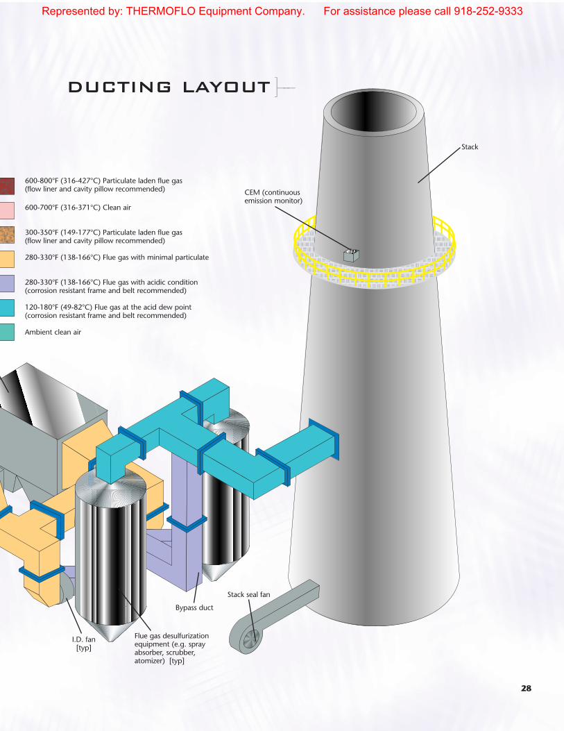
28
Flue gas desulfurizationequipment (e.g. sprayabsorber, scrubber, atomizer) [typ]
Stack seal fan
I.D. fan[typ]
CEM (continuousemission monitor)
600-800°F (316-427°C) Particulate laden flue gas (flow liner and cavity pillow recommended)
600-700°F (316-371°C) Clean air
300-350°F (149-177°C) Particulate laden flue gas (flow liner and cavity pillow recommended)
280-330°F (138-166°C) Flue gas with minimal particulate
280-330°F (138-166°C) Flue gas with acidic condition (corrosion resistant frame and belt recommended)
120-180°F (49-82°C) Flue gas at the acid dew point (corrosion resistant frame and belt recommended)
Ambient clean air
Bypass duct
Stack
DUCTING LAYOUT ]–-–
Represented by: THERMOFLO Equipment Company. For assistance please call 918-252-9333

ROUND CORNER-FOR BEST FATIGUEPERFORMANCE AND BEST VALUECorspan recommends the round corner design for allapplications. This design results in the lowest cornerstress if fit up and welding of the corner seams arecarefully controlled.
SINGLE MITER CORNER –CONVENTIONAL DESIGNCorspan also recommends the single miter design for corner construction. If a corner preference is notspecified, Corspan will use the single miter design for allconvolution profiles for lowest cost. This design allowsfor maximum amount of motion possible for a givenconvolution profile. The corner is a simple “pictureframe” construction.
DOUBLE MITER CORNER –VALUE ADDED – LOW CORNER FATIGUEThe double miter corner design offers lower corner fatigue than the conventional single miter corner orcamera corner designs. Welds are positioned away fromthe centerline of the corner and the highest stressed areaof the bellows.
CAMERA CORNER – NOT RECOMMENDEDCorspan does not recommend the use of camera cornerconstruction for rectangular metal expansion joints of anyconvolution profile. This is a method of assembly thatallows all corner seam welding to be performed on theoutside of the corner in a very accessible area with weldersof lower skill level than would be required for a singlemiter corner. However, this style corner results in deepcrevices at the corner that are corrosion initiators incertain flue gas conditions. The design also results in a reduction in movement capability.
29
RECTANGULAR METAL DUCT EXPANSION JOINTS
Corspan
-––[]–-–
Flexon® is a registered trademark of Senior Flexonics PathwayCorspan® is a registered trademark of Senior Flexonics PathwayUltrachem® is a registered trademark of Senior Flexonics PathwayInconel® is a registered trademark of Inco AlloysViton® is a registered trademark of E.I. DupontFluorel® is a registered trademark of 3MTeflon® is a registered trademark of E.I. Dupont
Represented by: THERMOFLO Equipment Company. For assistance please call 918-252-9333
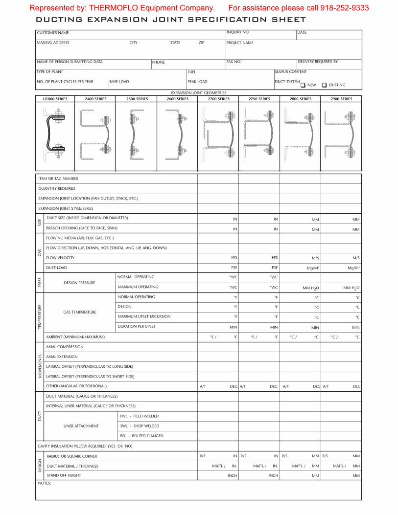
DUCTING EXPANSION JOINT SPECIFICATION SHEET
EXPANSION JOINT GEOMETRIES
ITEM OR TAG NUMBER
EXPANSION JOINT LOCATION (FAN OUTLET, STACK, ETC.)
QUANTITY REQUIRED
EXPANSION JOINT STYLE/SERIES
DUCT SIZE (INSIDE DIMENSION OR DIAMETER)
FLOWING MEDIA (AIR, FLUE GAS, ETC.)
BREACH OPENING (FACE TO FACE, SPAN)
FLOW DIRECTION (UP, DOWN, HORIZONTAL, ANG. UP, ANG. DOWN)
FLOW VELOCITY
NORMAL OPERATING
DUST LOAD
DESIGN PRESSURE
GAS TEMPERATURE
AMBIENT (MINIMUM/MAXIMUM)
AXIAL EXTENSION
AXIAL COMPRESSION
LATERAL OFFSET (PERPENDICULAR TO LONG SIDE)
LATERAL OFFSET (PERPENDICULAR TO SHORT SIDE)
DUCT MATERIAL (GAUGE OR THICKNESS)
OTHER (ANGULAR OR TORSIONAL)
INTERNAL LINER MATERIAL (GAUGE OR THICKNESS)
FWL - FIELD WELDED
BFL - BOLTED FLANGED
SWL - SHOP WELDED
CAVITY INSULATION PILLOW REQUIRED (YES OR NO)
NOTES:
MAXIMUM OPERATING
NORMAL OPERATING
DESIGN
MAXIMUM UPSET EXCURSION
DURATION PER UPSET
LINER ATTACHMENT
SIZ
EG
AS
PRES
STE
MPE
RATU
REM
OVE
MEN
TSD
UC
T
FPS
PSF
“WC
“WC
°F
°F
°F
MIN
°F / °F
A/T DEG
FPS
PSF
“WC
“WC
°F
°F
°F
MIN
A/T DEG
M/S
Mg/M3
MM H2O
°C
°C
°C
MIN
A/T DEG
CUSTOMER NAME INQUIRY NO. DATE
NAME OF PERSON SUBMITTING DATA
PROJECT NAMEMAILING ADDRESS CITY STATE ZIP
PHONE FAX NO. DELIVERY REQUIRED BY
TYPE OF PLANT FUEL SULFUR CONTENT
NO. OF PLANT CYCLES PER YEAR PEAK LOAD DUCT SYSTEMBASE LOAD�� NEW EXISTING
M/S
Mg/M3
MM H2O
°C
°C
°C
MIN
A/T DEG
DUCT MATERIAL / THICKNESS
RADIUS OR SQUARE CORNER
STAND OFF HEIGHT
DES
IGN
R/S IN
MAT’L / IN. MAT’L / MM
INCH MM
R/S MM
U1000 SERIES 2400 SERIES 2500 SERIES 2600 SERIES 2700 SERIES 2750 SERIES 2800 SERIES 2900 SERIES
°C / °C°F / °F °C / °C
IN
IN
IN
IN
MM
MM
MM
MM
MAT’L / MM
MM
R/S MMR/S IN
MAT’L / IN.
INCH
Represented by: THERMOFLO Equipment Company. For assistance please call 918-252-9333

Senior Flexonics Pathway2400 Longhorn Industrial Dr.New Braunfels, Texas 78130Tel Int: 1 830 629 8080Fax Int: 1 830 629 6899E-mail: [email protected]
www.flexonics.com1 800 854 2553
Represented by: THERMOFLO Equipment Company. For assistance please call 918-252-9333