reports date -...
TRANSCRIPT

1R- 2QS
REPORTS
DATE:

RITTER ENVIRONMENTAL & GEOTECHNICAL SERVICES 119 N . Colorado, Suite 201, Midland, Texas 79701
Bus: (915) 682-7404 • Metro: (915) 570-6007 • Fax: (915) 682-7440
FINAL CLOSURE REPORT
UNLINED SURFACE IMPOUNDMENT CLOSURE
PHILLIPS PETROLEUM COMPANY RECEIVED VACUUM FIELD IMPOUNDMENTS J A N 2 4 1994
SECTIONS 19, 20, 22, 24, 28 0 J L r n W Q C D l ( t T
TOWNSHIP 17 SOUTH, RANGE 35 EAST ° ' L ° , V
LEA COUNTY, NEW MEXICO
NOVEMBER 1993
PREPARED BY:
RITTER ENVIRONMENTAL & GEOTECHNICAL SERVICES (REGS)

m PHILLIPS PETROLEUM COMPANY EAST VACUUM GRAYBURG SAN ANDRES UNIT
« r ^ H T 1 L U P S P E T R 0 L E U M COMPANY OPERATOR

TABLE OF CONTENTS
I. Introduction and Background Page 1
1.1 Introduction Page 1
1.2 Background Page 2
1.3 Hydrogeology and Surface Conditions Page 2
1.4 Treatment Methodology Page 4
II. Scope of Work Page 4
2.1 Impoundment #1 (Polaris/Amerada) Page 4
2.2 Impoundment #2 (Penrose) Page 6
2.3 Impoundment #3 (Pennzoil) Page 7
2.4 Impoundment #4 (Bettis, Boyle & Stovall) Page 8
2.5 Impoundment #5 (Crown Central) Page 8
2.6 Impoundment #6 (Millard Deck) Page 10
2.7 Final Closure and Cover Page 10
III. Analytical Page 11
IV. Conclusions Page 12

APPENDIX
I. PHOTOGRAPHS
Photographic documentation of field events (pages 1-14)
II. MAPS
USGS Topographic Map Location Map Road Map Site Diagram (Millard Deck) Site Diagram (Polaris) Site Diagram (Penrose) Site Diagram (Crown Central) Site Diagram (Pennzoil) Site Diagram (Bettis, Boyle & Stovall) Land Map (Polaris and Penrose Impoundments) Land Map (Bettis, Boyle & Stovall, Millard Deck, Crown Central and Pennzoil)
III. ANALYTICAL RESULTS
Analytical results from Southwestern Laboratories, Midland, Texas
IV. CORRESPONDENCE
Letter to Mr. Jerry Sexton, dated August 13, 1993 Letter to Mr. Jerry Sexton, dated May 13, 1993
V. WELL RECORDS

I. INTRODUCTION AND BACKGROUND
1.1 INTRODUCTION
Ritter Environmental & Geotechnical Services (REGS) was contracted by Phillips
Petroleum Company to properly address the closure of six (6) unlined surface
impoundments located on Phillips operated leases in Lea County, New Mexico. These
impoundments were located in Sections 19, 20, 22, 24 and 28 of Township 17 South
Range 35 East of the East Vacuum Grayburg San Andres Unit currently operated by
Phillips Petroleum Company. The following is a listing of each impoundment name and
location:
1. Polaris Amerada 22-17S-35E
2. Penrose 24-17S-35E
3. Pennzoil 28-17S-35E
4. Bettis, Boyle & Stovall 19-17S-35E
5. Crown Central 20-17S-35E
6. Millard Deck 20-17S-35E
It was the aim of Phillips Petroleum Company to achieve permanent closure of the subject
impoundments while adhering to the published guidelines for impoundment closure set
forth by the New Mexico Oil Conservation Division (NMOCD) in February 1993. This
report will document the events and the subsequent results of the remedial efforts
achieved in the process of permanent closure of the above impoundments. The
accompanying analytical documentation (see Section III of this report) will provide
substantiated evidence that the recommended levels of remediation set forth in the
guidance document have been achieved by Phillips Petroleum Company.
PREPARED BY: Ritter Environmental & Geotechnical Services October 1993 1
1.2 BACKGROUND
The impoundments have been in use for various periods of time beginning as early as
1960 to 1965. All of the impoundments were established and utilized by previous
independent oil operators. The impoundments were discovered by Phillips Petroleum
personnel subsequent to unitizing the field and the naming of Phillips Petroleum Company
as the unit operator. Each impoundment's condition varied somewhat; however, all
contained residual tars, asphaltines, waxes and crude oil primarily from what appeared
to be excess crude and tank bottom residuals left in the impoundment when the leases
were abandoned by the previous operators. None of the impoundments appeared to
have received any wastes other than produced crude oil and/or tank bottoms.
The impoundment contents were analyzed for Total Petroleum Hydrocarbon fTPH) levels
prior to treatment. The TPH level was measured at 563,000 ppm in a sample taken
directly from the Pennzoil lease impoundment.
1.3 HYDROGEOLOGY & SURFACE CONDITIONS
The East Vacuum Grayburg San Andres Unit is located on the Llano Estacado of the High
Plains. The Llano Estacado is an isolated mesa covering a large part of eastern New
Mexico and western Texas. The Llano Estacado is locally called the Caprock and is a
depositional surface of low relief which slopes southeastward. The Caprock is comprised
of a thick layer of resistant caliche (limestone). The High Plains surface is almost
uniformly flat. Most rainfall runoff is trapped in shallow surface depressions, locally called
"buffalo wallows", where evaporation and downward percolation occur.
The primary source of drinking water in the area is the Ogallala formation. The Ogallala
ranges in thickness from 100 to 250 feet. Recharge of the aquifer is exclusively from
precipitation and subsequent downward percolation, primarily from the buffalo wallows.
PREPARED BY: Ritter Environmental & Geotechnical Services October 1993 2

Depth to water ranges from 50 to 100 feet in the general vicinity of the impoundments.
The Ogallala is the sole source aquifer in the area. No fresh water drinking sources were
located adjacent to any of the impoundments (within 1,000 feet). A buffalo wallow is
located approximately 1500 feet south of the Pennzoil impoundment and can be identified
on the topographic map included in the appendix of this report.
Near surface geological site conditions varied between locations. Generally, a moderately
dense but well consolidated caliche lime layer underlay most of the locations from a depth
of three to fifteen feet. The moderately dense caliche was intermittently overlain by a hard
dense layer of limestone which at times prevented the deepening of the treatment cells
beyond the dense layer. All locations were overlain by a thin veneer of soil composed
of silty to sandy clay that ranged in depth from a few inches to four feet.
Surface vegetation cover primarily consists of native prairie grasses including blue
gramma, side oats gramma and black gramma. Occasional mesquite and cactus also
are found. Mesquite is more dense on the eastern most portion of the field near the
Penrose impoundment.
The near surface limestone layer, in conjunction with relatively low annual rainfall amounts,
effectively limited the downward migration of the hydrocarbons contained in the
impoundments. Visually clean soils were identified in each impoundment after excavation
of the impoundment contents. Thus, the vertical limits of affected soil was determined
during the excavation and treatment process. All affected soil and impoundment contents
were treated by the process of solidification.
A water well survey was conducted to determine the proximity, location, depth and water
level of any fresh water wells located in the vicinity of the impoundments. Eleven water
wells were identified in the proximity of the impoundments. All of the identified wells were
drilled to provide fresh water for industrial usage (oil well drilling and potash exploration).
PREPARED BY: Ritter Environmental & Geotechnical Services October 1993 3

No domestic sources of potable water were identified within 1,000 feet of any
impoundment. Copies of the well records obtained from the State Engineers office are
included in the appendix of this report.
I. 4 TREATMENT METHODOLOGY
Solidification refers to a treatment system which is designed to improve the handling and
physical characteristics of wastes, to decrease the surface area across which the transfer
or loss of waste characteristics can occur and to limit the solubility of those waste
characteristics. This process effectively limits the lechate process and prevents the
material from entering the subsurface soils and groundwater. Solidification is achieved
by the addition of proprietary mixtures of cementious materials to the waste to form a
monolithic block of concrete type material. Solidification occurs through a process that
includes micro-encapsulation of the waste material.
II. SCOPE OF WORK
The scope of work for the Vacuum project included the necessary operations to address
the remediation by solidification of six unlined surface impoundments and the oily sludges
contained in those impoundments. Both olfactory and visual means were utilized to
identify the limits of affected soils. In this report, each impoundment will be addressed
separately.
2.1 IMPOUNDMENT #1 POLARIS/AMERADA
The Polaris/Amerada impoundment was located in the southwest quarter of Section 22,
Township 17 South, Range 35 East. The impoundment was an earthen containment and
level with the ground surface. No berm was associated with this impoundment. The
surface dimensions of the impoundment were approximately 100 feet by 100 feet.
PREPARED BY: Ritter Environmental & Geotechnical Services October 1993 4

Impoundment contents included weathered heavy asphaltines, tars, waxes, tank bottoms
and crude oil. Several years of weathering had obscured portions of the impoundment
by covering with air borne sand and soil. The remedial operations began on August 17,
1993.
The initial operations consisted ofthe placement of two trenches positioned perpendicular
north/south and east/west across the limits of the center of the impoundment. This was
performed in order to establish the vertical limits of affected soil and to determine if
pockets or pools of otherwise unobserved substances were involved. The average depth
of affected soil was limited to no more than five feet. No other liquids or solid materials
were identified in this assessment phase. A mass of highly viscous black liquid was
sealed below a three to five inch thick crust. After the vertical definition of the affected soil
depth was established, a perimeter trench was excavated to delineate the outer limits of
the impoundment.
After the vertical and horizontal limits of the impoundment and affected soil were
determined, four treatment cells were excavated around the established area. Reagent
chemical was placed into the cells prior to mixing with the impoundment contents and the
affected soil. The sludge materials and the affected soil were physically mixed with fresh
water and solidification reagent to accomplish the reaction in which the solidification
process occurs. The mixed materials were allowed a minimum of two weeks to harden
and cure. Each cell was core sampled after mixing to assure thorough mixing had taken
place. Proper sampling techniques and protocol were utilized in the acquisition, handling
and transport of all samples. Representative samples were submitted for analyses to
determine the degree of effectiveness of the solidification process. Analytical results are
presented in the Section III of this report.
SPECIAL NOTE: It should be noted that materials from the Penrose impoundment
have been transported to the Polaris/Amerada impoundment for treatment. This
PREPARED BY: Ritter Environmental & Geotechnical Services October 1993 5

was done due to the fact that the ground surface at the Penrose would not allow
the construction of below grade treatment cells due to near surface conditions.
Please refer to the special note in the Penrose portion of this report for a detailed
description of the events concerning the transfer and treatment of the Penrose
materials.
2.2 IMPOUNDMENT #2 PENROSE
The Penrose impoundment was located in the southwest quarter of Section 24, Township
17 South, Range 35 East. The impoundment consisted of an earthen berm elevated
above ground level to an approximate height of two feet. The impoundment contents
included very weathered and mostly dried heavy hydrocarbon materials including heavy
asphaltines, tars, waxes, tank bottoms and crude oil. The surface dimensions of the
impoundment were approximately 30 feet by 30 feet. The depth of the impoundment was
determined by excavation to be approximately three feet below the bermed surface.
Visually clean soil was identified in the bottom portion ofthe excavated impoundment after
the removal of the materials and affected soils. Operations began on August 23, 1993.
SPECIAL NOTE: Please note that on August 20,1993 Mr. Don Thorpe with Phillips
Petroleum Company contacted via telephone Mr. Jerry Sexton with the Hobbs
Office of the New Mexico Oil Conservation Division (NMOCD) and received verbal
approval to remove the impoundment & contents from the Penrose Lease and to
treat and remediate those materials at the location of the Polaris/Amerada lease.
The initial operations consisted of the removal of the impoundment and it's contents by
loading the materials onto transport vehicles and transferring those materials to the
Polaris/Amerada for treatment. This was done due to the fact that the impervious ground
surface around the Penrose impoundment would not allow the construction of below
grade cells for treatment. A single cell was constructed at the Polaris/Amerada to receive
PREPARED BY: Ritter Environmental & Geotechnical Services October 1993 6

the materials from the Penrose impoundment. The materials were thoroughly mixed by
mechanical blending with appropriate portions of the reagent chemicals and fresh water
to accomplish the solidification process.
Photographic documentation of the Penrose impoundment condition after removal of the
materials is included in the appendix of this report (see Photograph #11). The
impoundment location was brought back to grade with fresh top soil and levelled to
contour with the surrounding terrain.
2.3 IMPOUNDMENT #3 PENNZOIL
The Pennzoil impoundment was located in the northeast quarter of Section 28, Township
17 South, Range 35 East. The impoundment consisted of an earthen berm elevated
above ground level to an approximate height of three feet. The impoundment contents
included weathered heavy hydrocarbon materials including asphaltines, tars, waxes, tank
bottoms and crude oil. The surface dimensions of the impoundment were approximately
35 feet by 35 feet. The depth of the impoundment was determined by excavation to be
approximately eight feet below the bermed surface. Visually clean soil was identified in
the bottom portion of the excavated impoundment after the removal of the materials and
affected soil. Operations were commenced on August 21, 1993.
Preliminary operations consisted of preparation of a treatment cell in a "y" shaped
configuration. Near surface site conditions dictated the location and configuration of the
treatment cell due to the presence of a dense layer of limestone that would not allow cell
construction on the east and south sides of the impoundment, as would have normally
been done. The majority of the impoundment contents were in a liquid state and
contained trapped fresh water. The trapped water along with the sludge was solidified.
After the liquid contents were solidified, the remaining affected soil was treated by the
solidification process until only unaffected soil remained at the bottom of the excavation.
PREPARED BY: Ritter Environmental & Geotechnical Services October 1993 7

The empty impoundment was utilized as a separate treatment cell for the remaining
untreated soil.
2.4 IMPOUNDMENT #4 BETTIS, BOYLE AND STOVALL
The Bettis, Boyle and Stovall impoundment was located in the southeast quarter of
Section 19, Township 17 South, Range 35 East. The impoundment consisted of an
earthen berm elevated above ground level to an approximate height of four feet. The
impoundment contents included weathered heavy hydrocarbon materials including
asphaltines, tars, waxes, tank bottoms and crude oil contained in a heavy black viscous
sludge. The surface dimensions of the impoundment were approximately 125 feet by 100
feet. The depth of the impoundment was determined by excavation to be approximately
eight feet below the bermed surface. Visually clean soil was identified in the bottom
portion of the excavated impoundment after the removal of the materials and affected
soils. Operations were commenced on August 24, 1993.
Preliminary operations consisted ofthe construction of below grade treatment cells on the
north, south and west sides of the impoundment. Approximately three fourths (3/4) of
the impoundment contents were treated in the three cells. The remaining one fourth (1 /4)
was treated in the original impoundment. As before, fresh water was mechanically mixed
with the impoundment contents and the solidification reagent to perform the treatment
process. Fresh water, trapped in the impoundment contents, and affected soils were
treated by the solidification process.
2.5 IMPOUNDMENT #5 CROWN CENTRAL
The Crown Central impoundment was located in the northwest quarter of Section 20,
Township 17 South, Range 35 East. The impoundment consisted of an earthen berm
elevated above ground level to an approximate height of four feet. A near surface
PREPARED BY: Ritter Environmental & Geotechnical Services October 1993 8

impervious limestone caused significant difficulty in excavation of the treatment cells
around the periphery of the impoundment.
The contents included weathered heavy hydrocarbon materials including asphaltines, tars,
waxes, tank bottoms and crude oil contained in a heavy black viscous sludge. The
surface dimensions of the impoundment were originally calculated to be approximately
50 feet by 50 feet by visual inspection; however, upon excavation of the contents it was
discovered that the walls of the impoundment had leaked horizontally to the east and to
the south. This leakage had occurred beneath the current surface surrounding the
impoundment. As a result, the overall dimensions of the affected area increased to
approximately 75 feet by 75 feet. The depth of the impoundment was determined by
excavation to be approximately 10 feet below the bermed surface. Visually clean soil was
identified in the bottom portion of the excavated impoundment after the removal of the
materials and affected soils. Operations were commenced on August 24, 1993.
Preliminary operations consisted of the construction of below grade treatment cells on the
east, south and west sides of the impoundment. It was during the construction of the
treatment cells that the leakage was discovered from the original impoundment. Upon
the excavation of the east and south cells, free liquids were entering the newly
constructed cells from the direction of the impoundment. Photographic documentation
of these events are provided in the appendix of this report (see Photograph #25). It was
determined that all affected soils and liquids in the impoundment and the bordering walls
would require treatment by solidification. A significant amount of fresh water was trapped
in the impoundment and required treatment in addition to the liquid sludges. Fresh water
was mechanically mixed with the impoundment contents and the solidification reagent to
perform the treatment process. The empty impoundment was utilized to provide the
treatment cell for the solidification of the east and south wall affected soils and interstitial
liquid materials.
PREPARED BY: Ritter Environmental & Geotechnical Services October 1993 9

2.6 IMPOUNDMENT #6 MILLARD DECK
The Millard Deck impoundment was located in the northwest quarter of Section 20,
Township 17 South, Range 35 East. The impoundment consisted of an earthen berm
elevated above the ground level to an approximate height of three feet. A near surface
impervious limestone caused significant difficulty in the excavation of treatment cells
around the periphery of the impoundment. The contents included weathered heavy
hydrocarbon materials including asphaltines, tars, waxes, tank bottoms and crude oil
contained in a heavy black viscous sludge.
The surface dimensions of the impoundment were approximately 50 feet by 50 feet. The
depth of the impoundment was determined by excavation to be approximately four feet
below the bermed surface. Visually clean soil was identified in the bottom portion of the
excavated impoundment after the removal of the materials and affected soils. Operations
were commenced on August 30, 1993.
Three treatment cells were excavated around the perimeter of the impoundment to
provide a mixing area for the solidification reagent. These cells were constructed to the
north, south and east of the impoundment. Fresh water was mechanically mixed with the
impoundment contents and the solidification reagent to perform the treatment process.
The empty impoundment was demolished and distributed over the site after the removal
of all affected soils and contents.
Z l FINAL CLOSURE AND COVER
The solidified impoundments and treatment cells were allowed approximately two to three
weeks time to cure prior to covering. Each treatment cell was constructed with a two to
three foot freeboard that allowed for the placement of top soil over the cell area. Clean
topsoil was transported from local sources to cover the impoundments. A two to three
PREPARED BY: Ritter Environmental & Geotechnical Services October 1993 10

foot layer of top soil was placed over the top of the closed impoundments and solidified
cells. The top soil was contoured to match the surrounding terrain with a gentle slope
away from the center of the treatment area to prevent ponding and accumulation of
rainwater over the treatment area. Operations were completed on September 16, 1993.
J1L ANALYTICAL
Analyses of the solidified impoundment contents were conducted to determine the
effectiveness of the treatment. Each impoundment was core sampled immediately after
treatment. Samples were taken to represent a general cross section of that particular
impoundment's levels of constituents to be analyzed. Sample protocol adhered to US
EPA recommended methodology. Samples were collected by a clean stainless steel core
sampling device, placed in a laboratory cleaned glass sample container and sealed with
a lid containing a teflon lined septum. After collection, each sample was placed on ice
and chilled to approximately 4 ° C until transported to the laboratory for analyses. Proper
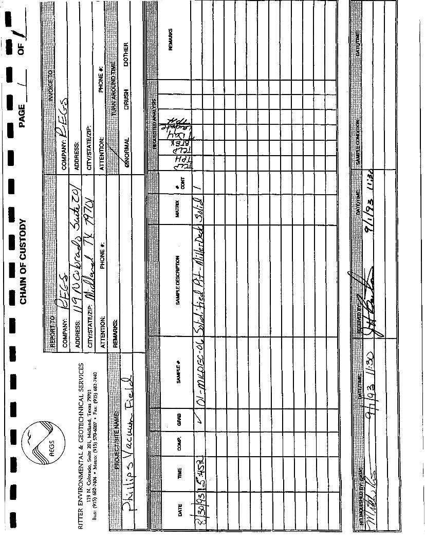
chain of custody documentation is provided in the appendix of this report. Lab QA/QC
data is provided along with the formal signed laboratory reports in the appendix of this
report. The core samples were analyzed by US EPA approved methodologies according
to SW 846 published methods. The samples were analyzed for Total Petroleum
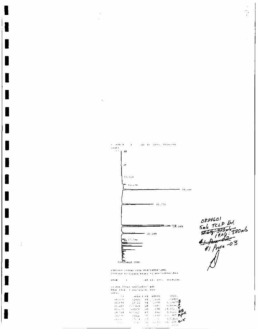
Hydrocarbons (TPH), Benzene, Toluene, Ethyl Benzene and Xylenes (BTEX). A seven day
lechate test was also performed on each sample. The seven day lechate test simulates
actual undisturbed conditions (as would normally be encountered with the buried mass).
This method allows the sample to remain in a partially water filled glass container for
seven days to simulate subsurface conditions. The lechate liquid is then measured for
the particular analyte of interest such as TPH and/or BTEX. The test was originally
designed to evaluate landfill leachate.
PREPARED BY: Ritter Environmental & Geotechnical Services October 1993 11

The analytical results were as follows:
TCLP ANALYSES
LEASE TPH mg/kg
TOTAL BTEX mg/L
BENZENE
mg/L
TOLUENE
mg/L
ETHYL BENZENE
mg/L
XYLENES
mg/L
7-DAY LEACHATE
TPH mg/L
Polaris Amerada 22 0.077 0.017 0.060 < 0.004 < 0.004 .73
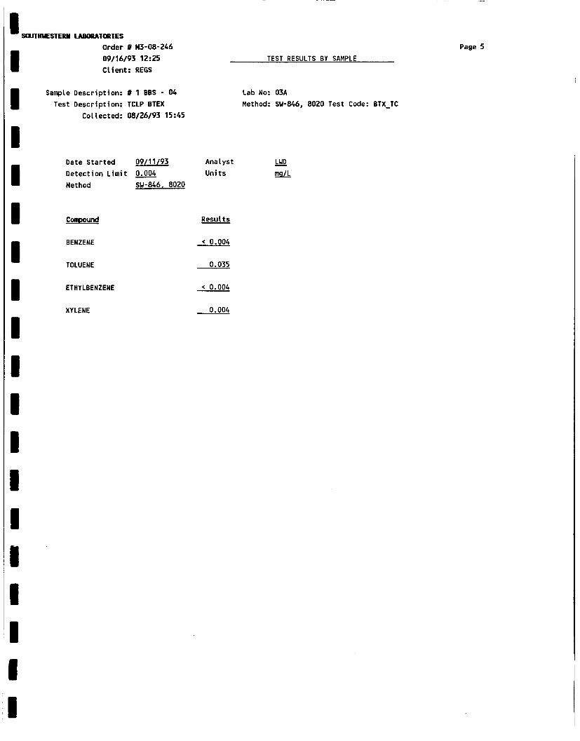
Pennzoil 30 0.088 0.012 0.027 0.014 0.035 1.6
Penrose 26 0.183 0.004 0.034 0.054 0.091 .53
Bettis, Boyle, Stovall
48 0.039 < 0.004 0.035 < 0.004 0.041 .57
Crown Central 46 0.107 0.010 0.034 0.022 0.041 1.0
Millard Deck 30 0.068 < 0.004 0.046 < 0.004 0.018 .63
JV, CONCLUSIONS
Evaluation of the above analytical results verifies that remediation of the six impoundments
found in the East Vacuum Grayburg San Andres Unit of Lea County, New Mexico has
been successfully completed. Review of the data supports the use of solidification as an
environmentally safe and sound technology to control and remediate the sludges and
affected soils found within the impoundments. The encapsulation/solidification process
effectively limits the teachability of the hydrocarbons previously left in the impoundments
and allows the land surface to return to a productive state. Locking up the hydrocarbons
by solidification prevents downward migration and the potential adverse effects on the
groundwater supply in the vicinity of the impoundments. Solidification allows the surface
to blend in with natural surroundings and permits grazing of livestock to reestablish itself
without fear of animal mortality or endangerment.
PREPARED BY: Ritter Environmental & Geotechnical Services October 1993 J2

The six surface impoundments have been properly closed in accordance with the
NMOCD published guidelines for "Unlined Surface Impoundment Closure" dated February
1993. No further actions are recommended or anticipated at this site.
RITTER ENVIRONMENTAL & GEOTECHNICAL SERVICES
Mitchelr R. Ritter, Managing Partner
PREPARED BY: Ritter Environmental & Geotechnical Services October 1993 13

Hitter Environmental K GrotechnK.ol Services P a Q e

Ritter Environmental & Geotechnical Services


Ritter Environmental A Geotechnical Services Page 4

12. PENNZOIL Pre treatment
13. PENNZOIL Treatment cell
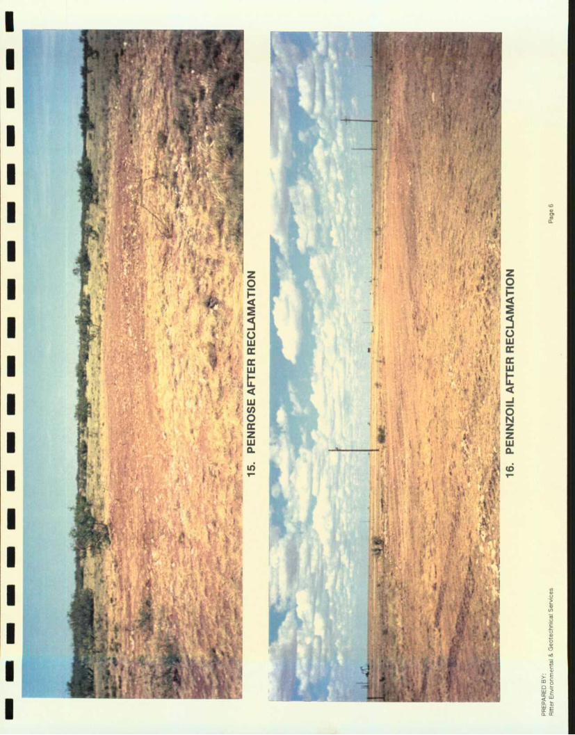
14. PENNZOIL After reclamation
- - j - » » » i 3 i * l f c * r f O - ' • f e t e
PREPARED BY: Ritter Environmental & Geotechnical Services Page 5


30. MILLARD DECK Impoundment contents
31. MILLARD DECK Freshly solidified cell
32. MILLARD DECK Showing clean soil below impoundment
PREPARED BY: Ritter Environmental & Geotechnical Services Page 13


Ritter Environmental & Geotechnical Services
PHILLIPS PETROLEUM Vacuum Field Impoundments
Lea County, New Mexico
ROAD MAP 1
November 1993 1


Treatment Cell
I N Top View
Cross Section
Treatment Cell Penrose Cell
2 Top Soil
Cross Section
^ — Solidified Material
Side View
Ritter Environmental & Geotechnical Services
PHILLIPS PETROLEUM
SITE DIAGRAM Polaris Impoundment #1 (22-17-35)
Horizontal Scale 1" = 50' (No Vertical Scale)
November 1993
_ _ _ _ _ _ _ _ — _

I N
Top View
Penrose Impoundment
Ritter Environmental & Geotechnical Services
PHILLIPS PETROLEUM
SITE DIAGRAM Penrose Impoundment #2 (24-17-35)
Horizontal Scale 1" = 15' (No Vertical Scale) 1
November 1993 1

Top View
Pennzoil Impoundment
1
Treatment Cell
Cross Section
Side View
Top Soil
Ritter Environmental & Geotechnical Services
PHILLIPS PETROLEUM
SITE DIAGRAM Pennzoil Impoundment #3 (28-17-35)
Horizontal Scale 1" = 15' (No Vertical Scale)
November 1993
Solidified Material

Treatment Cell
Cell Bettis Boyle & Stovall Cell Cross Section
Solidified Material
Ritter Environmental & Geotechnical Services
PHILLIPS PETROLEUM
SITE DIAGRAM Bettis Boyle & Stovall Impoundment #4 (19-17-35)
Horizontal Scale 1" = 50' (No Vertical Scale)
November 1993

Top View
I N
Crown Central Impoundment
Cell Cross Section
Cell
Treatment Cell
Side View
Ritter Environmental & Geotechnical Services
PHILLIPS PETROLEUM
SITE DIAGRAM Crown Central Impoundment #5 (20-17-35) Horizontal Scale 1" = 25' (No Vertical Scale)
November 1993

Top View I N
Miller Deck Impoundment Cell -Cross Section
Treatment Cell
Side View Top soil
Solidified Material
Ritter Environmental & Geotechnical Services
PHILLIPS PETROLEUM
SITE DIAGRAM Miller Deck Impoundment #6 (20-17-35)
Horizontal Scale 1" = 25' (No Vertical Scale)
November 1993

• S i l l
3*
Bird
8 - 7 7 5 *
)
5-* ( O M I O - . T « j
A P C J HBP
Sun Oper,to
4 I 93 LM- lAYt 9 0 € «
T.L. log ram Tn-Serv . r t j |
r - . . Stevens.erai 0 , 1 j M.B.P.
Sf 1
i 4 ' 'Shoe. Bar S t " 1
h t » 3 * r a » i N i p . H M • ms | i I S M i
TO irsoo
Penrose (24-17-35) 9 I M I C H . i W J
TDUOQ
-iifiia rf^pV
»>MZ _n 4TI _A\ •artWtstH
I l l j S ' ' " ^
• U n t i l ukiflLfof
B T A
S u n r a
Ritter Environmental & Geotechnical Services
PHILLIPS PETROLEUM l w 1 Location of Impoundment
LAND MAP Vicinity of Water Well Polaris Impoundment (22-17-35)
Penrose Impoundment (24-17-35)
November 1993


S O U T H W E S T E R N L A B O R A T O R I E S
Materials, environmental and geotechnical engineering, nondestructive, metallurgical and analytical services 1703 West Industrial Avenue • P.O. Box 2150 • Midland, Texas 79702
Report of tests on S o i l Client Rit ter Environmental & Geotechnical Services Delivered by Mitch Ritter
File No. Report No. Report Date Date Received
6750100 80622 05-13-93 March 1993
Identification Phi l l ips Petroleum Co.
REPORT OF TOTAL PETROLEUM HYDROCARBONS
Date of Analysis Analyst
05-12-93 S. Stovall
sample Identif icat ion
Method SW846,3550;EPA 418.1 MDL 5.0 mg/kg
Results, mg/kq
Pennzoil P i t 563000
*Denotes "less than"
Copies: Ritter Environmental & Geotechnical Services
Attn: Mitch Ritter
Reviewed by
Our letters and reports are (or the exclusive use of the client to whom they are addressed. The letters and reports shall not be
reproduced except In full without the approval of the testing laboratory. The use of our name must receive prior written approval.

SOUTHWESTERN LABORATORIES 1703 West Industrial Avenue P.O. Box 2150, Midland, Texas 79702 915/683-3349
Client REGS 119 N. Colorado Suite 201 Midland, Tx. 79701
Attn: Mitch Ritter
Project Polaris - Amerada Pk.
Client No. 6750100 Report No. M3-08-247 Report Date 09/16/93 12:30
Date Sampled 08/20/93
Sample Type Soi1
P.O. #
Sampled By Client
Transported by Mitch Ritter
Date Received 08/30/93
Lab No. M3-08-247-01
Sample Identification # 1 - Polam - 01
Reviewed By
SOUTHWESTERN LABORATORIES
ALLAN B. JOHNSTON '

SOUTHWESTERN LABORATORIES Order # M3-08-247 Page 2 09/16/93 12:35 : TEST RESULTS BY SAMPLE Client: REGS
Sample: 01A # 1 - Polam - 01 Collected: 08/20/93 15:21
Detection Date Test Name Method Result Units Limit Started Analyst 7 DAY TPH EPA 418.1 0.73 mg/L 0.50 09/15/93 ABJ TCLP TPH EPA 418.1 22 mg/kg 5.0 09/11/93 LWD

SOUTHUESTERH LABORATORIES
Order « M3-08-247 09/16/93 12:30
Client: REGS
Page 3
TEST RESULTS BY SAMPLE
Sample Description: # 1 - Polam - 01
Test Description: TCLP BTEX
Collected: 08/20/93 15:21
Lab No: 01A
Method: SU-846, 8020 Test Code: BTX_TC
Date Started 09/11/93 Analyst LUD
Detection Limit 0.004 Units mg/L
Method SW-846. 8020
Compound Results
BENZENE 0.017
TOLUENE 0.060
ETHYLBENZENE < 0.004
XYLENE < 0.004

fcr i t I .' * • l '.

JP^i SOUTHWESTERN LABORATORIES 1703 West Industrial Avenue * P.O. Box 2150, Midland, Texas 79702 * 915/61
Client No. 6750100 Report No. M3-08-246 Report Date 09/16/93 12:25
Attn: Mitch Ritter
Project Phillips Vacuum Field
Client REGS 119 N. Colorado Suite 201 Midland, Tx. 79701
Date Sampled 08/23/93 08/30/93
Sample Type Soi 1
P.O. #
Sampled By Client
Transported by Mitch Ritter
Date Received 08/30/93
Lab No. M3-08-246-01 M3-08-246-02 M3-08-246-03 M3-08-246-04 M3-08-246-05
Sample Identification #1 Prose - 03 # 1 Penn - 02 # 1 BBS - 04 # 1 - CC -05 01-MILDEC-06
SOUTHWESTERN LABORATORIES
Reviewed By ALLAN B. JOHNSTON

SOUTHWESTERN LABORATORIES
Order # M3-08-246
09/16/93 12:33
Client: REGS
Sample: 01A #1 Prose - 03
Test Name
7 DAY TPH
TCLP TPH
Sample: 02A # 1 Penn - 02
Test Name
7 DAY TPH
TCLP TPH
Sample: 03A # 1 BBS - 04
Test Name
7 DAY TPH
TCLP TPH
Sample: 04A # 1 - CC -05
Test Name
7 DAY TPH
TCLP TPH
Sample: 05A Ol-MILDEC-06
Test Name
7 DAY TPH
TCLP TPH
TEST RESULTS BY SAMPLE
Collected: 08/23/93 16:06
Method
EPA 418.1
EPA 418.1
Result Units 0.53 mg/L 26 mg/kg
Collected: 08/23/93 13:51
Method
EPA 418.1
EPA 418.1
Result
1.6
30
Units
mg/L
mg/kg
Collected: 08/26/93 15:45
Method
EPA 418.1
EPA 418.1
Result
0.57
48
Uni ts
mg/L
mg/kg
Collected: 08/27/93 18:32
Method
EPA 418.1
EPA 418.1
Result
1.0
46
Units
mg/L
mg/kg
Collected: 08/30/93 15:45
Method
EPA 418.1
EPA 418.1
Result
0.63
30
Units
mg/L
mg/kg
Page 2
Detection Date
Limit Started
0.50 09/15/93
5.0 09/11/93
Detection Date
Limit Started
0.50 09/15/93
5.0 09/11/93
Detection Date
Limi t Started
0.50 09/15/93
5.0 09/11/93
Detection Date
Limit Started
0.50 09/15/93
5.0 09/11/93
Detection Date
Limit Started
0.50 09/15/93
5.0 09/11/93
Analyst
ABJ LWD
Analyst
ABJ
LWD
Analyst
ABJ
LWD
Analyst
ABJ
LWD
Analyst
ABJ
LWD

SOUTHUESTERN LABORATORIES Order # M3-08-246 09/16/93 12:25 Client: REGS
Sample Description: #1 Prose - 03 Test Description: TCLP BTEX
Collected: 08/23/93 16:06
TEST RESULTS BY SAMPLE
Lab No: 01A Method: SU-846, 8020 Test Code: BTX_TC
Date Started 09/11/93 Analyst LWD Detection Limit 0.004 Units mg/L Method SW-846. 8020
Compound Results
BENZENE 0.004
TOLUENE 0.034
ETHYLBENZENE 0.054
XYLENE 0.091

SOUTHUESTERM LABORATORIES Order # H3-08-246 09/16/93 12:25 Client: REGS
Page 4 TEST RESULTS BY SAMPLE
Sample Description: # 1 Penn - 02 Test Description: TCLP BTEX
Collected: 08/23/93 13:51
Lab No: 02A Method: SU-846, 8020 Test Code: BTX_TC
Date Started 09/11/93 Analyst LWD Detection Limit 0.004 Units mg/L Method SW-846. 8020
Compound Results
BENZENE
TOLUENE
ETHYLBENZENE
XYLENE
0 012
0 027
0 014
0 035
SOUTHUESTERM LABORATORIES
Order # H3-08-246
09/16/93 12:25
Client: REGS
Sample Description: # 1 BBS - 04
Test Description: TCLP BTEX
Collected: 08/26/93 15:45
TEST RESULTS BY SAMPLE
Lab No: 03A
Method: SU-846, 8020 Test Code: BTX_TC
Date Started 09/11/93 Analyst LUP
mg/L Detection Limit
Method
0.004
SW-846. 8020
Units
Compound Results
BENZENE < 0.004
TOLUENE 0.035
ETHYLBENZENE < 0.004
XYLENE 0.004

SOUTHWESTERN LABORATORIES
Order # M3-08-246
09/16/93 12:25
Client: REGS
Page 6
TEST RESULTS BY SAMPLE
Sample Description: # 1 - CC -05
Test Description: TCLP BTEX
Collected: 08/27/93 18:32
Lab No: 04A
Method: SU-846, 8020 Test Code: BTX_TC
Date Started 09/11/93 Analyst LWD
mg/L Detection Limit
Method
0.004
SW-846. 8020 Units
Compound Results
BENZENE 0.010
TOLUENE 0.034
ETHYLBENZENE 0.022
XYLENE 0.041

SOUTHWESTERN LABORATORIES
Order # M3-08-246
09/16/93 12:25
Client: REGS
Sample Description: 01-MILDEC-06
Test Description: TCLP BTEX Collected: 08/30/93 15:45
Page 7
TEST RESULTS BY SAMPLE
Lab No: 05A
Method: SU-846, 8020 Test Code: BTX_TC
Date Started 09/11/93 Analyst
Detection Limit 0.004 Units
Method SW-846. 8020
LWD
mg/L
Compound
BENZENE
TOLUENE
ETHYLBENZENE
XYLENE
Results
< 0.004
0.046
< 0.004
0.018

T U t T l H b L t iTOP
; 1 o u 11 i t i n u l H t Cf 7 I 4 6 56 4 . 6 td*
j l o r i n i c ro< : 4 i i « <J r- •* i r i i o M i I.-7 I 4 n 5 6 u . r" fi 0
iEP I t . 1 i b j 1 , 1 4 1 : 1 1
5 ! C ; I | H L F I I . E S H : H ? 1 4 f 5 t 8 . £ US
F E M i F I 1.1 ! M I £> • H » 5 t i . f f l ,
... • n te
. k ; o * " i i 6 1 - -t •-.
0 5>

: t f I 1 • I f 1 •• " • H
I l i t
Li!:
11 N T T H
1*1 fify
C l o l i n i n i n l l I I I * H i (',• 14.-LS4 . B in :
S l o r i r . 9 ftrocsiliU H I M 10 H M i . " I 4 4 . t F U
iEF I I . I 1
; i i ' . l l i < l . F I L E I K I ( i 7 H " i « . S I K
F E n t F I U : H : o ; n : ' M J 4 . F h i l
. . F t M
J . •. :: I '
V - . " 4 . - l
' l t r > . f t
- . . . o i L.fc

• t - m i H
ae
(' Y I I • 1
11 itTi *
C l o s i n g i i » r . * l t i l * M l w ? I 4 ( J u e O . B H C
i i o n n i e r o t « i i i 4 o c ^ i t o K i u 7 H 8 M . r P ( j
p U M i 7 - £ F l 1 • I S 9 * 1 * 1 3 4 1 "S4
I I OH H i . M L £ i n i O r 1 4 t f 9 t 0 . t ' I I ' '
f E M I- F I L E : M l i ' 1 4 £ U e. 0 . f *
R T V f E l i 1 Cl 1 H H K E H \
i 1 4 1 3 i«4r t 'J r 6 . t 5 y
o 7 ? 7 5 I 4 u 7 pe . 1 ; 1
- :* j " • •' E' , 1 iiE»
. I "i l
1 . V * S 4 4
t H 1 4 - ^ 6 :> fcP . i l *>
J U , *J *? "} I I
1 , i l O o i
1
| . 1 . 1
." i .J
*j 2 0 J 4 1
, 1 - . t r t
. b
.•b
l • V
'• K-
. 1 t ) 4
. i l u
. 1 ii
1
J U , *J *? "} I I
1 , i l O o i
1 ' " '
* ; 11 -
1 : " 1
.. •-• ' •* . 1
. 1 1 *
. i •« 4
, l l »


u. O
UJ
I
I D O u. O
A a
4
o
.3
o
1
o
o
i
Oc
CO
w
1 a Ui oo tn c » J t in < , O ON U <s TT
o | S
21!
2 •§ o
Z op OS
5 to-
2
12
LU
Ui
0,
(2-
0-
WE,
Ul 2 P
Y
fi
\
o
to
o
X
is
I
.2 \0 oQ
s2
*M.
I
IV)
^3
Jt a
<5


RITTER ENVIRONMENTAL & GEOTECHNICAL SERVICES 119 N. Colorado, Suite 201, Midland, Texas 79701
Bus: (915) 682-7404 • Metro: (915) 570-6007 • Fax: (915) 682-7440
May 13, 1993
Mr. Jerry Sexton District Manager New Mexico Oil Conservation Division P.O. Box 1980 Hobbs, New Mexico 88240
Re: Surface Impoundment Closure - Phillips Petroleum Company/Vacuum Field Lea County, New Mexico
Dear Mr. Sexton:
Pursuant to our telephone conversation the other day, I am writing in reference to your request for a proposal from Ritter Environmental & Geotechnical Services (REGS) to provide our services in connection with the proposed remedial activities on six unlined earthen pits in the Vacuum Field of Lea County, New Mexico.
As these pits are being decommissioned by the operator, Phillips Petroleum Company, it is their desire to adhere to the currently established guidelines for pit (surface impoundment) closure as published by the NMOCD in February 1993 and to address the closure of these pits in a safe and cost effective manner. As an alternative to transporting and landfilling of these wastes (where in only a transfer of the problem occurs) and to long term bioremedial activities that would involve many months and possibly years to accomplish the current remedial guidelines as set forth by the NMOCD, we (REGS) through currently developed solidification techniques propose to treat the waste materials on site by stabilization of the waste through solidification.
We are currently utilizing combinations or separate application of Portland cement, kiln dust and or fly ash to bind the wastes into a hardened monolithic block of concrete type material. Solidification refers to treatment systems which are designed to improve the handling and physical characteristics of such wastes, to decrease the surface area across which the transfer or loss of the waste characteristics can occur and to limit the solubility of those waste characteristics. This treatment effectively limits the leachate process and prevents the materials from entering the subsurface soils and groundwater. Stabilization techniques, such as solidification, have benefits primarily in limiting the solubility of the waste or by detoxifying the waste contaminants, even though the physical characteristics of the waste may or may not appear to be changed. It is intended that the following

Mr. Jerry Sexton May 13, 1993 Page 2
procedures will be followed in the performance of our services:
I. Preliminary Site Evaluation - Includes a visual inspection (and sampling) of each pit and the surrounding area to determine site specific conditions such as; nearby surface waters, streams, surface soil types and depths, proximity to groundwater supply wells, physical and chemical properties ofthe contents of each pit and the treatability of those contents.
II. Treatment/Solidification - After careful preparation of the site for safe operations the solidification process begins. Solidification begins with the physical addition of the appropriate product(s) in the correct proportions to the type of waste involved. Mechanical mixing methods are utilized to thoroughly blend the waste material and the appropriate solidifying agent(s) with correct proportions of water. At this time, a curing process is allowed to take place for a period of approximately 48 hours. Post treatment core samples will be taken from each pit to determine TCLP parameters for volatile organic compounds (VOCs) such as Benzene and Total BTEX.
III. Site Reclamation - After treatment, the site will be reclaimed by placing native soils over the treated area and recontouring the site back to the original grade (if possible).
I have included analytical results of two separate series of bench tests we have performed on actual pit material from the Vacuum field. These tests have generated very pleasing results, wherein we have solidified pit sludge and performed TCLP, BTEX, and TPH analyses on the solidified samples. As you can see, in each case the solidified material renders the levels of BTEX and TPH leachability to acceptable levels in accordance with the NMOCD guidelines.
The first series of analyses dated 4-19-93, report no. 80622 from Southwestern Laboratories revealed very low BTEX levels of treated materials ranging from non-detectable Ethylbenzene and Xylenes to a TPH of 111 to 782 mg/kg. This bench test was run on pit sludge from the Vacuum field samples
A second series of analyses was run and dated 5-3-93. The series labeled B-1 through B-5 are the Buckeye area pit samples from the Vacuum field. Here again the analytical results of the treated pit sludge are within current NMOCD guidelines.
In reference to analytical tests currently run we would like to suggest to the NMOCD an

Mr. Jerry Sexton May 13, 1993 Page 3
alternative to testing the pit material after treatment. We have determined through past experience with the solidification process that the TCLP procedure and methodology currently being used for identification of elevated levels of toxic compounds may not be the most appropriate methods for the analysis of actual site conditions post treatment.
We would suggest the adoption of a seven (7) day leachate test in lieu of the TCLP analysis. The seven (7) day leachate test is a non-violent test in which actual sub surface conditions are simulated by submersing the sample to be tested in deionized water for a period of seven (7) days prior to analyses of the water. This test simulates actual saturated groundwater conditions at the site and relates to teachability as opposed to the violent tumbling action the samples are subjected to in the TCLP methodology. Also, approximately the 20 to 1 dilution factor utilized in the TCLP methodology is not utilized in the seven (7) day leachate method.
We have obtained the following results utilizing the seven (7) day leachate test on the same samples previously run for TCLP:
SAMPLE # TPH BENZENE ETHLYBENZENE TOLUENE XYLENE mg/l mg/l mg/l mg/l mg/l
B2-2 7.1 .006 .022 .008 .015 B-3 4.0 <.004 <.004 <.004 <.006 B-4 2.8 <.004 .011 <.004 .008
The methodology for the seven (7) day leachate test is as follows and is a part of the accepted methodology utilized by the Texas Water Commission (TWC) for landfill evaluations:
7-Day Distilled Water Leachate Test
This test is intended only for dry, solid wastes, i.e., waste materials without any free liquids.
1. Place a 250 gm. (dry weight) representative sample of the waste material in a 1500 ml. Erlenmeyer flask.
2. Add 1 liter of deionized or distilled water into the flask and mechanically stir the material at a low speed for five (5) minutes.
3. Stopper the flask and allow to stand for seven (7) days.

Mr. Jerry Sexton May 13, 1993 Page 4
4. At the end of the seven (7) days, filter the supernatant solution through a .45 micron filter, collecting the supernatant into a separate flask.
5. subject the filtered leachate to the appropriate analysis.
Although we feel the above methodology is more appropriate, we will provide TCLP analyses should the above methodology not be approved.
I have included photographs of pit solidification performed in Southeast Montana, northeast of Wyoming and southwest of Wyoming. These pits were solidified with appropriate state agency approval.
We have also included copies of two excerpts from the Superfund Innovative Technology Evaluation program (SITE) funded and directed by the EPA to evaluate new technologies. These excerpts, although not identical to our process, are similar and provide some insight into the feasibility of our work.
We are hereby requesting your approval to apply and utilize the above described technology in the treatment of the surface impoundments referenced at the beginning of this correspondence. Your response should be directed to me at the letterhead address.
Thank you for taking the time to review this proposal. Your comments and assistance will be greatly appreciated.
MRR/bk cc: Mr. Bill Olson/NMOCD - Santa Fe, New Mexico

RITTER ENVIRONMENTAL & GEOTECHNICAL SERVICES 119 N. Colorado, Suite 201, Midland, Texas 79701
Bus: (915) 682-7404 • Metro: (915) 570-6007 • Fax: (915) 682-7440
May 13, 1993
Mr. Jerry Sexton District Supervisor New Mexico Oil Conservation Division P.O. Box 1980 Hobbs, New Mexico 88240
Re: Phillips Petroleum Company, Vacuum Field, Surface Impoundment Closure
Dear Mr. Sexton:
On May 12, 1993 you were sent correspondence and enclosures concerning surface impoundment closures in the Vacuum and Cabin Lake fields of Lea and Eddy counties, respectively. It has come to my attention that the proposed pit closure in Eddy County is under the jurisdiction of the Artesia offices of the NMOCD and not your district. Therefore, I would like to apologize for the inclusion of the Eddy County pit closure request in your correspondence.
We have rewritten and redirected our proposal to the Artesia NMOCD office for their approval of the pit closure in Eddy County. Enclosed please find an amended and corrected proposal concerning six Vacuum Field pits. You will note the change from four to six pits as we have identified two additional pits we wish to close in the Buckeye area.
I apologize for any confusion. If you have any questions or comments, please contact me at your earliest convenience at (915) 682-7404.
Sincerely,
Mitchell Ritter
MRR/amc Enclosures

RITTER ENVIRONMENTAL & GEOTECHNICAL SERVICES 119 N. Colorado, Suite 201, Midland, Texas 79701
Bus: (915) 682-7404 • Metro: (915) 570-6007 • Fax: (915) 682-7440
August 13,1993
Mr. Jerry Sexton District Manger New Mexico Oil Conservation Division P.O. Box 1980 Hobbs, New Mexico 88240
Re: Surface Impoundment Closure - Phillips Petroleum Company - Vacuum Field, Lea County, New Mexico
Dear Mr. Sexton:
Please be advised Ritter Environmental & Geotechnical Services will began solidification operations on approximately seven pits in the Vacuum Field on August 18,1993. If you would like to observe this process, please contact our office at 915/570-6007.
Should you have any questions, please do not hesitate to contact us.
Sincerely,
BK/s

Form WR-23 SANTA FE 0
STATE ENGINEER OFFICE
WELL RECORD INSTRUCTIONS: This form should be executed in triplicate, preferably typewritten, and submitted to the nearest district office of !!•:: State Engineer. Al l sections, except Section 5, shall be answered as completely and accurately as possible when any well is drilled, repaired or deepened. When this form is used as a plugging record, only Section IA and Section 5 need be completed.
Section 1
B-t
/
(A) Owner of welL. Street and Number.. City Hobbs
J^rjTjac^Po.tgsh.CPj
P.O Box 610
State New Mexico
Well was drilled under Permit No 1-5.85.0..
|£N_E y 4 NE J/ t NW- tt of Section (B) Drilling Contractor-Abbott, Bros ,
and is located in the
.1.9.„..Twp..J75 Rge....35E
License No.._WH=4A_.. Street and Number.JL*.QjJtox .£37_ City Hobbs
(Plat of 640 acres)
Elevation at top of casing in feet above sea leveL.
Drilling was commenced Feb,...0...
Drilling was completed Ejeb._SL
State -Jt±m.Me?uca._-19.A4-l9._6i..
..Total depth of welL. 240 feet
State whether well is shallow or artesian_sbailow Depth to water upon mmpletinn hole caved
Section 2 PRINCIPAL WATER-BEARING STRATA
No. Depth in Feet Thickness in
Feet Description of Water-Bearing Formation No.
From To
Thickness in Feet
Description of Water-Bearing Formation
1 100 235 135 Alternatina beds of fine grained sand, silt and gravel 2
3
4
5
Section 3 RECORD OF CASING
Dia In.
Founds f t .
Threads ln
Depth Feet Type Shoe
Perforations Dia In.
Founds f t .
Threads ln Top Bottom
Feet Type Shoe From To
. i
<y
Section 4 RECORD OF MUDDING AND CEMENTING CO
Depth ln Feet Diameter Hole in in.
Tons Clay
No. Sacks of Cement
{ / > • 11
m Methods User ^ From To
Diameter Hole in in.
Tons Clay
No. Sacks of Cement
{ / > • 11
m Methods User ^
0 5 4-1/4 1
-s- - T I r - i TP. co .—-, rr.
Section 5
Name of Plugging Contractor-
Street and Number 1
Tons of Clay used
Plugging method used.
Plugging approved by:
PLUGGING RECORD
City.. ..License No-
State:.
.Tons of Roughage used . -Type of roughage.
-Date Plugged.. _19_ Cement Plugs were placed as follows:
Basin Supervisor
Date Received
FOR USE OF STATE ENGINEER ONLY
I
No. Depth of Plug
No. of Sacks Used No. From To
No. of Sacks Used
1 0 5 I
File No._ L - F t f h b Use._jf^M Location No.

Section 6 LOS OF WELL
Depth in Feet Thickness in Feet Color Type ot Material Encountered
From To Thickness in Feet Color Type ot Material Encountered
0 0 .5 0 .5 dark brown alluvium
0.5 15 14.5 It brn caliche
15 75 60 It brn fine grained, poorly cemented sand
75 77 2 white dense lens with chest stringers
77 80 3 It brn fine grained, poorly cemented sand
80 90 10 It brn fine grained unconsolidated sand
90 130 40 It brn fine grained poorly cemented sand
130 140 10 It brn fine grained unconsolidated sand
140 195 55 It brn fine to med. poorly cemented sand
195 210 15 red arenaceous siltstone
210 235 25 variegated quartz gravel
235 240 5 red srilsrone top Santa Rosa
The undersigned hereby certifies that, to the best of his knowledge and belief, the foregoing is a true and correct record of the above described welL
v WelrDriller
•

Form WH-23 STATE ENGINEER OFFICE
WELL RECORD SANTA FE INSTRUCTIONS: This form should be executed in triplicate, preferably typewritten, and submitted to the nearest district office of the State Engineer. Al l sections, except Section 5, shall be answered as completely and accurately as possible when any well is drilled, repaired or deepened. When this form is used as a plugging record, only Section IA and Section 5 need be completed.
Section 1 (A) Owner of well P h i l l i p s Pflt.i-nl mm flnmpqny
Street and Number Box._448___
City Buckeye, State _MeaLMnxlco..
..and is located in the Well was drilled under Permit No. ..L-.4S29A.
y4-S3IL._.y*...SW. Vt of Section.19-.-. -Twp.l7-S Rge3-5£ (B) Drilling ContractorJ.«^«_ily-.^is.wkiteL Street and Number JB.QX___5.6_
City
Drilling was commenced. Drilling was completed
. License No.HJDSL9_
Hobbs,... ..Ma.re.h..J25......
March 30.
State ._lI.3.Yt.Maxi.c.Q.._..
19.£&_
- 19.M_ (Plat of 640 acres)
Elevation at top of casing in feet above sea leveLHntoQ_v__n.__.__ Total depth of well_2JLQ.
State whether well is shallow or artesian__§ha.lJkOW Depth to water upon completion.. JUL
Section 2 PRINCIPAL WATER-BEARING STRATA
No. Depth in Feet Thickness in Description of Water-Bearing Formation No.
From To Feet Description of Water-Bearing Formation
1 170 205 35 Sand, f i n e , unconsolidated 2
3
4
5
Section 3 RECORD OF CASING
Dia in.
Pounds f t .
Threads ln
Depth Feet Type Shoe
Perforations Dia in.
Pounds f t .
Threads ln Top Bottom
Feet Type Shoe From To
10 3/L 36 none 0 210 210 none 112 210
Section 4 RECORD OF MUDDING AND CEMENTING
Depth in Feet Diameter Hole In in.
Tons Clay
No. Sacks of Cement Methods Used '-•a
C.'"> t o
From To
Diameter Hole In in.
Tons Clay
No. Sacks of Cement Methods Used '-•a
C.'"> t o
i } , , . 1 • ; • °-' > j J
Section 5
Name of Plugging Contractor
Street and Number
Tons of Clay used! —Tons of Roughage used
Plugging method used-
Plugging approved by:
PLUGGING RECORD
City..
...License No-
State
..Type of roughage.. _Date Plugged.. _10_
T Cement Plugs were placed as follows:
Basin Supervisor
FOR _>l STATE ENGINEER ONLY } V->-
Date R e c e i g a ^ - i ^
No. Depth of Plug
No. of Sacks Used No. From To
No. of Sacks Used
ITse PPP . Locat ion No.

' Form WR-23 STATE ENGINEER OFFICE
WELL RECORD
Section 1
INSTRUCTIONS: This form should be executed in triplicate, preferably typewritten, and submitted to the nearest district office of the State Engineer. All sections, except Section 5, shall be answered as completely and accurately as possible when any well is drilled, repaired or deepened. When this form is used as a plugging record, only Section IA and Section 5 need be completed.
(A) Owner of weiL. Cltlea-Saryice.-Oil Co^Li street and Wnmw $> Bob Webster t 100 Temple Drive City Hobba.-- state .Jte.K.MexlCQ Well was drilled under Permit No .k~??M and is located in the
SE_y4-lJW....._y4-MW. Vi of Section... 20_ Twp.JLZ_a„.JRge._l£_IL._
(B) Brillmg Contractor.-M»Ji». .Burke License N o — J J ^ L -
Street and Number.BOX __
City ! Hobba state Hew Mex. Drilling was commenced— J u l y 26
Drilling was completed - J u l y 27 (Plat ot 640 acres)
Elevation at top of casing in feet above sea leveL
19-55.-19_5JL
State whether well is shallow or artesian ShBllPff'" -Total depth of welL 110
-Depth to water upon completion. 60
Section 2 PRINCIPAL WATER-BEARING STRATA
No. Depth in Feet Thickness In Description of Water-Bearing Formation No.
From To Feet Description of Water-Bearing Formation
1 60 110 50 Water Sand 2
3
4
S
Section 3 RECORD OF CASING
Dia in.
Pounds ft.
Threads in
Depth Feet Type Shoe
Perforations Dia in.
Pounds ft.
Threads in Top Bottom
Feet Type Shoe From To
6 5/8 19 8 0 104 104 none 74 104
Section 4 RECORD OF MUDDING AND CEMENTING Depth ln Feet
From To Diameter
Hole in ln . Tons Clay
No. Sacks of Cement Methods Used
Liu ,i AUG 15 il
Section 5
Name of Plugging Contractor
Street and Number
Tons of Clay used Tons of Roughage used
Plugging method used
Plugging approved by:
PLUGGING RECORD
City..
7"i»V,.U>|ll|q!|2|3|4|5|6
License- No
. State:
-Type of roughage-
-Date Plugged.. -19_ Cement Plugs were placed as follows:
Basin-Bupervlsbr
Date Received
FOR USE OF STATES' ENGINEER'O^TLY
AUG 4 1955 OTFICE
GROUND V-'ATH r1 "FWISOR ROSV/Ul, I - - ' .'••SAiCO , B
File No..
No. Depth of Plug
No. of Sacks Used No. From To
No. of Sacks Used
_Use_ ..Location No. / / £ L

Section 6 LOS OF WELL
Depth in Feet Thickness in Feet Color Type of Material Encountered
From To Thickness in Feet Color Type of Material Encountered
o 2 2 Soil TL 19 17 Caliche 19 51 32 Tight Sand 51 60 9 Dry Sand 60 110 50 Water Sandi
The undersigned hereby certifies that, to the best of his knowledge and belief, the foregoing is a true and correct record of the above described well.
Well Driller

Form WR-23 STATE ENGINEER OFFICE
WELL RECORD
9 SANTA FE
INSTRUCTIONS: This form should be executed in triplicate, preferably typewritten, and submitted to the n rarest district office of the State Engineer. All sections, except Section 5, shall be answered as completely and accurately as possible when any well is drilled, repaired or deepened. When this form is used as a plugging record, only Section IA and Section 5 need be completed.
Section 1 (A) Owner of well._M_-_-.-_-..JDrllllng._.P nm p any Street and Number._jBaX._5.Q94
City ...Mdl_m.<_+._l£X_i£ , State
Well was drilled under Permit No L-f>9-4Q.(.E-). and is located in the
HE-y*—SE—.y4.-SW_.-_y4 of Section.._20 -Twp.17- Rge.35____
(B) Drilling Contractor-_---AbbQ.t±___3r.QS._ License No .W__-4.6._
Street and Number £_____6.57. .
City HQbba.,__l_-_I___. State _, ___
(Plat of 640 ai:res)
Elevation at top of casing in feet above sea leveL
State whether well is shallow or artesian—ah.al_Lo.__.
Drilling was commenced .._ .April...28U9..7.2._.
Drilling was completed _.._-_-£.?ii.._?2j._..l_)_7..?._ 19_ 19..
..Total depth of welL. .135.
Section 2 PRINCIPAL WATER-BEARING STRATA
..Depth to water upon completion. 85-
No. Depth in Feet Thickness in
Feet Description of Water-Bearing Formation No.
From To
Thickness in Feet
Description of Water-Bearing Formation
1 SO aand water 2 , CO
' — 1
3
4
. . r~_ 3
4
5
Section 3 RECORD OF CASING
Dia in.
Pounds f t .
Threads in
Depth Feet Type Shoe
Perforations ~ Dia in.
Pounds f t .
Threads in Top Bottom
Feet Type Shoe From <-To
r o
7 23 10 1 126 126 none 70 26
Section 4 RECORD OF MUDDING AND CEMENTING
Depth in Feet Diameter Hole in in.
Tons Clay
No. Sacks of Cement Methods Used
From To
Diameter Hole in in.
Tons Clay
No. Sacks of Cement Methods Used
Section S
Name of Plugging Contractor-
Street and Number
Tons of Clay used ...
Plugging method used
Plugging approved by:
PLUGGING RECORD
City.... ..License No State
.Tons of Roughage used . .: Type of roughage. -Date Plugged .19..
Cement Plugs were placed as follows:
FOR USE OF STA fe i_t_tl
33IJJ0 W®" Date Received.
No. Depth of Plug
No. of Sacks Used No. From To
No. of Sacks Used
File No. .. L...GSIP.. Location No.

Section 6 LOG OF WELL
Depth From
in Feet
To Thickness
in Feet Color Type of Material Encountered
0 1 1 brown fJHTf" q f o s o i l
, 1 22 21 g r a y 22 85 6 V hrnwri aanrl ( t i r»ht> 85 ' 135 50 brown sand wotf tT .
; i . , ; / ' • ••;
<
• • • • ; '.'-.!." '.'> > •
1
J
The undersigned hereby certifies that, to the best of his knowledge and belief, the foregoing is a true and correct record of the above described welL
!.'- • [.'••••:.•• • .T;V:--V i£hj^,At/'f fteito . .• : ' - . • . . : • Well Driller •-• • •

Form WR-23 STATE ENGINEER OFFICE SANTA FE
WELL RECORD INSTRUCTIONS: This form should be executed in triplicate, preferably typewritten, and submitted to the nearest district office of the State Engineer. A l l sections, except Section 5, shall be answered as completely and accurately as possible when any well is drilled, repaired or deepened. When this form is used as a plugging record, only Section IA and Section 5 need be completed.
Section 1 (A) Owner of WelL Mnrmim T h - i l l i n g r inmpnriy
Street and Nnmher Box 6094
City Midland, Texas State
Well was drilled under Permit No.....__-7Q24.tE.)
S S , Y * S S y4 . - M . - y 4 of Section 2Q.._.Twp..
.and is located in the
J I Rge.__5
(B) Drilling Contractor.
Street and Number
City
A b b o t t B r o s . . License No.WDri6_ Box 637
HQ.b.ba._.____I!L..
Drill ing was commenced..
Drill ing was completed.—.
State _
.N.s.v t . . . .2.Q^_19.72„
(Plat of 640 acres)
Elevation at top of casing in feet above sea level
State whether well is shallow or artesian U-LallQW..
.Nov. . 21 . , ...193-2-
19
:19.__._
..Total depth of welL__J_lQ..
..Depth to water upon completion.-_6Q_
Section 2 PRINCIPAL WATER-BEARING STRATA
No. Depth in Feet Thickness in
Feet . r Description of Water-Bearing Formation No.
From To
Thickness in Feet
. r Description of Water-Bearing Formation
1 80 130 50 water sand 2 O'}
— 1 — O , ' — 1
3 - 1 r v j
.•/', 1 • 1
4 ,-' f j rT:
5
•' ;, >-• j . _ . . •> - " • m
Section 3 RECORD OF CASING - rri -a 3 -
Dia in.
Pounds f t .
Threads ln
Depth Feet Type Shoe
Peribrallpns r o Dia in.
Pounds f t .
Threads ln Top Bottom
Feet Type Shoe From c_To
c~, 1—• 7 23 m no nn n n n p an no
Section 4 RECORD OF MUDDING AND CEMENTING
Depth ln Feet Diameter Hole In in.
Tons Clay
No. Sacks of Cement Methods Used
From To
Diameter Hole In in.
Tons Clay
No. Sacks of Cement Methods Used
Section 5
Name of Plugging Contractor
Street and Number :
Tons of Clay used Tons of Roughage used
Plugging method used —
Plugging approved by:
PLUGGING RECORD
City..
'Basin Su]
FOR USE OF STAT43 EttOOwSf* ONLY
HUQ o__iNI3M3 3IV.LS Date Received - , ... —, , -_,
cn:«Ul/ I I JJU Z/GI J
File No..
.Xicense No-
State..
-Type of roughage..
-Date Plugged.. _19_
Cement Plugs were placed as follows:
No. Depth of Plug
No. of Sacks Used No. From To
No. of Sacks Used
_Use_ ..Location No.

Form WR-23
BANTA FE STATE ENGINEER OFFICE
WELL RECORD INSTRUCTIONS: This form should be executed in triplicate, preferably typewritten, and submitted to the nearest district office of the State Engineer. All sections, except Section 5, shall be answered as completely and accurately as possible when any well is drilled, repaired or deepened. When this form is used as a plugging record, only Section IA and Section 5 need be completed.
Section 1 (A) Owner of well P M l l l p a . _ P & t r . Q l e U ^
Street and Number Box_477 City -Buckeye > State J!.e_L.Maxl__i Well was drilled under Permit No..L-_(_-2.9 and is located in the
y4..BW- y_~SE Vi of Section...20 .-Twp.-J.7S. ...Rge -3.5E--
(B) Drilling Contractor Q^___..__^SlSM__ite.___ License No...ID9-9.
Street and Number JB.OX....5.6 - . City H-}.B.bS.+.. State J_9_lL.Me.Xi.ClO
Drilling was commenced.NO-W-3-r-Drilling was completed K.QY_ 5.*—
(Plat of 640 acres)
Elevation at top of casing in feet above sea level
State whether well is shallow or artesian—.Slialloai..
..Total depth of welL. 19.2-
19..._6_>_
19...i_6.
..Depth to water upon completion 6CL
Section 2 PRINCIPAL WATER-BEARING STRATA
No. Depth in Feet Thickness in
Feet Description of Water-Bearing Formation No.
From To
Thickness in Feet
Description of Water-Bearing Formation
1
2 70 Ift^ Sand & sand rock 1
2 180 190 10 Sand 3
4
5
3
4
5
3
4
5
Section 3 RECORD OF CASING
Dia in.
Pounds f t .
Threads in
Depth Feet Type Shoe
Perforations ° ' Dia in.
Pounds f t .
Threads in Top Bottom
Feet Type Shoe From , ! __To
1". i c_>
__1Q_3V 4 28 none 0 192 192 none 76 I , •19]5". __1Q_3V • i"
__1Q_3V
-
Section 4 RECORD OF MUDDING AND CEMENTING c_>
Depth in Feet Diameter Hole in in.
Tons Clay
No. Sacks of Cement Methods Used
From To
Diameter Hole in in.
Tons Clay
No. Sacks of Cement Methods Used
.___-___-.___-___-
Section 5
Name- of Plugging Contractor
Street and Number
Tons of Clay used .Tons of Roughage used
Plugging method used
Plugging approved by:
PLUGGING RECORD
City.. ...License No..
State -Type of roughage..
_Date Plugged- ..19_ Cement Plugs were placed as follows:
FOR USE -1<\ ' •• I I M ) (SE TOF (STATE mCWNEER
Basin Supervisor
-jfJF|STATKE_t- ONLY
?2-'8W- 6-AON 9961
No. Depth of Plug
No. of Sacks Used No. From To
No. of Sacks Used
File No _..__..:..^___?-_- Use.^ _5i_<2 Location No. J5^3S~,-&QJ..&&.

Reviled June 1.7]
STATE ENGINEER OFFICE
WELL RECORD
Section 1. GENERAL INFORMATION
(A) Owner of *eii MpbJ.1 Prod. Texas & New Mexico owner!. Well HalLo-i-street or Post ^ ^ 4 ^ ^ % Glenn's Water-yen service , i nc . " ,,-City and State Box 692 Tatum, New Mexico OOdbY , i r r '- '
. and is located in the: Well was drUled under Permit Nn !•- 1 0 . 0 6 2
a K W NE K SE i/ 4 o f S e c l i o n 2 2 Township 1 7 " S
, Range. 35- E .N.M.P.M.
b. Tract No._ . of Map No.. of the.
c. Lot No.. . of Block No.. .of the. Subdivision, recorded in . . County.
d. X* the.
. feet. Y=_ . feet, N.M. Coordinate System.
(B) Drillingm-t^nr (-Term's Water Well Service, Inc . L i c e n s e M . WD - l & l
Address ROY fig? Tatum. New Mexico 8826?
_ .... _ o o no „ . . . ?_?_R0
. Zone in _ Grant.
Drilling Began , 2 - 2 - 8 9
Elevation of land surface or
Completed 2-2-89 Typ, >__.•. Rotary
at well is ft. Total depth of w e l l - l i t 2
9 7/8 Size of hole _ _ in.
Completed well is C_) shallow CD artesian. Depth to water upon completion of well. 50
Section 2. PRINCIPAL WATER-BEARING STRATA
-f t .
- f t .
Depth in Feet Thickness in Feet Description of Water-Bearing Formation
Estimated Yield (gallons per minute) From To
Thickness in Feet Description of Water-Bearing Formation
Estimated Yield (gallons per minute)
50 115 65 Sand 120
Section 3. RECORD OF CASING
Diameter (inches)
6 5/8
Pounds per foot
.156
Threads per in.
Depth in Feet Top Bottom
Length (feet) Type of Shoe Perforations
From
70
To
lk?-
Plugging Contractor. Address Plugging Method Date Well Plugged Plugging approved by:
'Section 4. RECORD OF MLIDDING AND . TNT1NG Depth in Feet Hole
Diameter Sacks.
of Mud Cubic Feet of Cemem From To
Hole Diameter
Sacks. of Mud
Cubic Feet of Cemem
Section 5. PLUGGING K:
State Engineer Representative
Date Received February 9. 1989
L-10,062 File No
FOR USE OF STATE ENl.
Quad
OWD Use
'NLY
Method of Placement
'• Depth in Feet Cubic Feet
of Cement '• Top Bottom Cubic Feet of Cement
1
•> ) »
FWL FSL.
. Location No.. 17.35.22.42321

Section 6. LOG OF HOLE Depth in Feet Thickness
in Feet Color and Type ol Material Encountered From To
Thickness in Feet Color and Type ol Material Encountered
0 1 1 S o i l
1 13 12 Cole-he
13 27 lk Hard Rock
27 50 23 3-ind wi th Rock
50 115 65 Sand (water)
115 1/+0 25 Sand wi th Red Cl trinRore
Section 7. REMARKS AND ADDITIONAL INFORMATION
co **
CO CO
rT. c a
m o X -n
n
m _ 3
The undersigned hereby certifies that, to the best of his knowledge and belief, the foregoing is a true and correct record of the above described hole.
Driller
INSTRUCTIONS: This form should be exec in liiplicate, preferably typewritten, and sur g e d to the appropriate district office of the Stilts Engineer. All sections, except tion 5, shall be answered as completely and a^urately as possible when any well is
' "tf,! nr deepened. When this form is used as a plnpcinp n-rnrri, only Section Ha) and Siriinn 5 need be completed.

o
(This form to be executed In
WELL RECORD
Date of Receipt J « W « y 7 , 1953
Name of permittee * " * ? 5 j ! U L A " * ?
Street or P.O., . ? » . . . 9 » . . ? ? * _ . ^ ^ 7 . , City and State....
Permit No
1. Well location and description: The jjhjjljilBi. well Is located In SB %, (shallow or artesian)
Hol s, M w JtodLoo
..81 v.,
-Vt of Section... 22 Township.. , Range...
casing above sea level, rf..f*&;? '.. feet; diameter of hole,
depth to water upon completion, _4t_ ....feet; drilling waa commenced.
Elevation of top of
„.inchea; total depth, mi... ....feet;
15
and completed.. Deesaber 17 52
2. Principal Water-bearing Strata:
Depth In Feet
, 19....«_T.~; name of drilling contractor...
.., Address Box 637, Habbe, M. &V .
../Mott.lR».t*...
Driller's License No... WD 46
From To Thickness Description of Water-bearing Formation
No. 1 105 » Water Sand
No. 2
No. S
No. 4
No. B
3. Casing Record:
Diameter In Ineliei
Pound* per f t .
Threads Depth of Casing or Liner per Inch Top Bottom
Feet of Castas
..7?...
Type of Shoe
...IkXML
Perforations From To
55!, ..105i_
O
4. If above construction replaces old well to be abandoned, give location: — ~...Vi, - Vi, M
of Section , Township , Range.— ; name and address of plugging contractor,
date of plugging... 19- _.: describe how well was plugged: ....
FEB 10 1953
S T A T E ENGINEER PY
JAN 13 1953 O F ! I C E
U < S E I I ? W C T MEXICO

STATE ENGINEER OFFICE Form, WR-23
SAMTft f.B f^ju^f^\4SSam j INSTRUCTIONS: This form should bbWdited in triplicate, preferably typewtittoi, fand submitted toJthe nearest district office of the State Engineer. Al l sections, except Section 5, shall be answered as completely "and accurately as possible when any well is drilled, repaired or deepened. When this form is used as a plugging record, only Section IA and Section 5 need be completed. Section 1
(A) Owner of welUErl Servic-e-jr.l lXiftg—Company Street and Number City _ Midland state Texas
Well was drilled under Permit No..JL-45.Q3 and is located in the
VAJMJ.LV*, HE...y4 of Section....2.4 .Twp.._12a Rge._J3iSE-
.License No.JB0.rl5.4_
(Plat of 640 acres)
Elevation at top of casing in feet above sea leveL
State whether well is shallow or artesian
( B ) D r i l l i n g Cnnt r f l r tn r S t o n e D r i l l i n g Cp
Street and Number City Seminole,Texas ,
Drilling was commenced
Drilling was completed
state laxas_ 19_
19..
..Total depth of welL.
Section 2 PRINCIPAL WATER-BEARING STRATA
-Depth to water upon completion..
No. Depth in Feet Thickness in
Feet Description of Water-Bearing Formation^ . v;
d cr-No.
From To
Thickness in Feet
Description of Water-Bearing Formation^ . v; d cr-
1
2
3
4 _ f - f ^ ^
5 I '
-n • •
Section 3 RECORD OF CASING
Dia in.
Pounds f t .
Threads In
Depth Feet Type Shoe Perforations Dia
in. Pounds
f t . Threads
In Top Bottom Feet Type Shoe
From To
Section 4 RECORD OF MUDDING AND CEMENTING
Depth in Feet Diameter Hole in in.
Tons Clay
No. Sacks of Cement Methods Used
From To
Diameter Hole in in.
Tons Clay
No. Sacks of Cement Methods Used
Section 5
Name of Plugging Contractor-
Street and Number _?_>___
PLUGGING RECORD
..E.._--...__akfir.. City3.eminol£
-License No. SUte_T.e___S_
Tons of Clay used .n_0J_fi Tons of Roughage used Jicma-
Piugginfimethodused...Regular CemexiJi-Plugging approved/by:)
FOR USE
Date Receiva n 13IM1SIQ
ONLY
S2:i Hd 8! 130
File Ko..__JzS.4..$0--2
1961
Type of roughage_l______
Date Plugged 9-16- _19-6i_
Cement Plugs were placed as follows:
No. Depth of Plug
No. of Sacks Used No. From To
No. of Sacks Used
0 6 3 sack cement
Us«> O. Location No. V.?' 3 J."- ~?JL3-C?P.

Section 6 LOG OF WELL
Depth in Feet Thickness ••• in Feet .
t ; •- 1 i - 1
. - <i Color Type of Material Encountered From To' ' j
Thickness ••• in Feet .
t ; •- 1 i - 1
. - <i Color Type of Material Encountered
The undersigned hereby certifies that, to the best of his knowledge and belief, the foregoing is a true and correct record of the above described well.
Well Driller
J t

r A i t . N.M. 67501
STATE ENGINEER OFFICE
W E L L R E C O R D
Section I . GENERAL INFORMATION
ised June 1972
(A) ownerotweii P h j U i p s r^trjQjgiim Company Street or Post Office Addressr.?* \0 ffQX 1 1 7 8 City and Stafe, L Q f c L r ' g t d r " , T.&\"1 L I s x l C Q 3 3 2 6 0
Owner's Well NoT,-/, B.?<j-?.-')
Well was drilled under Permit Nn L - 2 f S 2 f f i - f t k f o and is located in the:
of Section 2 8 Township 1 7 3 . Range. ire .N.M.P.M.
b. Tract No.. , of Map No. of the .
c. Lot No.. . of Block No. . o f the. Subdivision, recorded i n . . County.
d. X = . the.
. feet, Y=_ . feet, N.M. Coordinate System.
(B) Drilling Contractor 0 . R . L i U S S l e w h j t e License No Vv'DQQ
Address P. 0 C Box 56 r Hobbs, New Mexico 882/.0
. Zone in
_ Grant.
Drilling Began S e p t . 2 6 - 7 5 Completed W n v , 1 - 7 5 T y r " tools
Elevation of land surface or at well is f t . Total depth of well_2_L5.
Completed well is shallow artesian. Depth to water upon completion of well
Section 2. PRINCIPAL WATER-BEARING STRATA
Size of hole 1 5 in.
f t .
J2H ft.
Depth in Feet Thickness in Feet Description of Water-Bearing Formation
Estimated Yield (gallons per minute) From To
Thickness in Feet Description of Water-Bearing Formation
Estimated Yield (gallons per minute)
70 nn Sanrl fr. Tnr\]r
120 7^ n tt n
Section 3. RECORD OF CASING
Diameter (inches)
10 3/4
Pounds per foot
Threads per in.
none
Depth in Feet
Top Bottom
-215_
Length (feet)
-215-
Type of Shoe
none
Perforations
From
OS- -210-
Section 4. RECORD OF MUDD1NG AND CEMENTING
Depth in Feet Hole Diameter
Sacks of Mud
Cubic Feet of Cement Method of Placement
From To Hole
Diameter Sacks
of Mud Cubic Feet of Cement Method of Placement
Section 5. PLUGGING RECORD
Plugging Contractor Address : Plugging Method Date Well Plugged Plugging approved by:
State Engineer Representative
FOR USE OF STATE ENGINEER ONLY
Date Received September 27, 1978 Quad FWL FSL.
No. Depth in Feet Cubic Feet
of Cement No. Top Bottom
Cubic Feet of Cement
1 i
3 4

Form WR-: 9 STATE ENGINEER OFFICE PI No?
ips-State 28-1
WELL RECORD 1- ?1f' INSTRUCTIONS: This form should be executed in triplicate, preferably typewritten, and submitted to the nearest district office of the State Engineer. All sections, except Section S, shall be answered as completely and accurately as possible when any well is drilled, repaired or deepened. When this form is used as a plugging record, only Section IA and Section 5 need be completed.
Section 1 (A) Owner of well. .Zapata JEetroleuiiL..Corp.: Street and Number BOX 2216 ;
City _. Midl&ftd. State . XfiX&fiL
Well was drilled under Permit No and is located in the
-s_f_^_%-MEL y_.—HE....y4 of Section 28 .Twp.l7S Rge 35E
(B) Drilling Contractor.-JSd-JBurke License N o . . t t B = l l l ~
Street and Number ^
City ....HDhhft
Drilling'was commenced..
Drilling was completed
(Flat ot 640 acres)
Elevation at top of casing in feet above sea leveL_.3-95^-
..Sept. _SepJ_s _2_..
state Naw Mexico. 195-8...
195$..
..Total depth of welL J.25-.
State whether well is shallow or artesianShallOW. Depth to water upon completion 65-
Section 2 PRINCIPAL WATER-BEARING STRATA
No. Depth
From n Feet
To
Thickness in Feet
Description ot Water-Bearing Formation
1 102 125 23 Water Sand
2 — * X
78 13 T.ig^ti Water
3
4
5
Section 3 RECORD OF CASING
Dia in.
Pounds f t .
Threads in
Depth Feet Type Shoe
Perforations Dia in.
Pounds f t .
Threads in Top Bottom
Feet Type Shoe From To
7 20 ft n 120.7 120.7 none 93 120 w^f
Section 4 RECORD OF MUDDING AND CEMENTING
Depth in Feet Diameter Hole in ln.
Tons Clay
No. Sacks ot Cement
_ t CX) Methods Used^ rn From To
Diameter Hole in ln.
Tons Clay
No. Sacks ot Cement
_ t CX) Methods Used^ rn
^ ' 1
"p. CT> , J — f O
-V -rt
Section 5
Name of Plugging Contractor-
Street and Number
Tons of Clay used
Plugging method used
Plugging approved by:
PLUGGING RECORD J J ro CO CD
City..
..License No..
State:.
.Tons of Roughage used . Type of roughage.. -Date Plugged .19-
Cement Plugs were placed as follows:
FOR USE C F S
Date Received.
Basla Sunnw
,SEPl0ffl58
File No.
O F F I C E GROUND WATB« SUP^BO*
MHWIU, ww wm9
No. Depth of Plug
No. of Sacks Used No. From To
No. of Sacks Used
-Use ..Location No.

Section 6 LO© OF WELL
Depth in Feet Thickness in Feet » , •»• Color ,. Type ol Material Encountered
From To Thickness
in Feet » , •»• Color ,. Type ol Material Encountered
o 1 1 ftur f*n c S o i l l 22 21 Q^licln* -
22 • 33 ''• Sand Tineht
55 7$ Sanrl S<jf*t
78 102 24 Sflirl Tight 102
The undersigned hereby certifies that, to the best of his knowledge and belief, the foregoing is a true and correct record of the above described well.
WeU Driller

STATE ENGINEER OFFICE
WELL RECORD Wimble State "K1
INSTRUCTIONS: This form should be executed in triplicate, preferably typewritten, and submitted to the nearest district office of the State Engineer. Al l sections, except Section 5, shall be answered as completely and accurately as possible when any well is drilled, repaired or deepened. When this form is used as a plugging record, only Section IA and Section 5 need be completed.
Section 1 (A) Owner of v,e\\^JUMBLE^niL...Am^Bi,
Street and Number R^Q. Box 21 QO.
City Hobbs State MeW—Mextoo__._
Well was drilled under Permit No......L.~2^32. and is located in the
Vi-SK YASE.-...VA of Section....^. .Twp....IZ..S.....Rge..3a_iL
(B) Drilling Contractor. Ahho.ijL^Br.Q.iKer.S License No. $HL=A£L.
Street and Number E*.(U~Itax.-&27.
City .KQ-hbs State Rm.JiSxto_CL___
Drilling was commenced..
Drilling was completed
-April-2- 19.. Aprtl 2 19.M..„
(Plat of 640 acres)
Elevation at top of casing in feet above sea level
State whether well is shallow or artesian.
..Total depth of welL-._i.4GL
Section 2
aia. Depth to water upon completion..
PRINCIPAL WATER-BEARING STRATA
-flfl-
No. Depth in Feet Thickness in
Feet Description of Water-Bearing Formation No.
From To
Thickness in Feet
Description of Water-Bearing Formation
1
2 80 140 60 water sand 1
2
3
4 t o •• •
V % 5
Section 3 RECORD OF CASING
Dia in.
Pounds f t .
Threads ln
Depth Feet Type Shoe
Perforations Dia in.
Pounds f t .
Threads ln Top Bottom
Feet Type Shoe From To
7 26 10 0 140 140 open RO IdO
Section 4 RECORD OF MUDDING AND CEMENTING
Depth In Feet Diameter Hole In ln.
Tons Clay
No. Sacks of Cement Methods Used
From To
Diameter Hole In ln.
Tons Clay
No. Sacks of Cement Methods Used
Section 5
Name of Plugging Contractor
Street and Number
Tons of Clay used .Tons of Roughage used
Plugging method used
PLUGGING RECORD
City-
Plugging approved by:
Basin Supervisor
Date
FpR. USE OFj STATE ENGINEER ONLY
Jtriiiiji'l:
V l :8 HU 91 Udtf i|9EI
File No ^» ~~~ S"e> 6 2* -Use.
..Xicense No..
State: -Type of roughage..
-Date Plugged- 40-Cement Plugs were placed as follows:
No. Depth of Plug
No. of Sacks Used No. From To
No. of Sacks Used
..Location No./jL_3 ^Ji£.:Jftf3_