reportno.:eed32i00089501 page1of35 cover page fcc … · reportno.:eed32i00089501 page1of35 cover...
TRANSCRIPT

Report No. : EED32I00089501 Page 1 of 35
COVER PAGE
FCC TEST REPORTProduct : Mobile Printer
Trade mark : Rongta
Model/Type reference : RPP02N-BU
Serial Number : N/A
Report Number : EED32I00089501
FCC ID : 2AD6G-RPP02N-BU
Date of Issue : Aug. 16, 2016
Test Standards : 47 CFR Part 15 Subpart B (2015)
Test result : PASS
Prepared for:
XIAMEN RONGTA TECHNOLOGY CO., LTD.
3F-1/E Building, No.195 Gaoqishe, Gaodian Village, Dianqian Street
Office, Huli District, Xiamen City
Prepared by:
Centre Testing International Group Co., Ltd.
Hongwei Industrial Zone, Bao’an 70 District,
Shenzhen, Guangdong, China
TEL: +86-755-3368 3668
FAX: +86-755-3368 3385
Tested By: Compiled by:
Tom chen (Test Project) Kevin yang (Project Engineer)
Reviewed by: Approved by:
Sheek Luo (Reviewer) Sheek Luo (Lab supervisor)
Date: Aug. 16, 2016Check No.: 2392191403

Report No. : EED32I00089501 Page 2 of 35
1 Version
Version No. Date Description
00 Aug. 16, 2016 Original
Report No. : EED32I00089501 Page 3 of 35
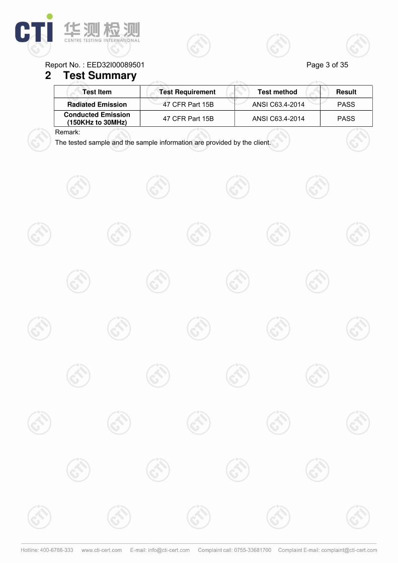
2 Test Summary
Test Item Test Requirement Test method Result
Radiated Emission 47 CFR Part 15B ANSI C63.4-2014 PASS
Conducted Emission(150KHz to 30MHz)
47 CFR Part 15B ANSI C63.4-2014 PASS
Remark:
The tested sample and the sample information are provided by the client.

Report No. : EED32I00089501 Page 4 of 35
3 Contents
Page
1 COVER PAGE................................................................................................................................................................1
2 VERSION.........................................................................................................................................................................2
3 TEST SUMMARY...........................................................................................................................................................3
4 CONTENTS.....................................................................................................................................................................4
5 GENERAL INFORMATION..........................................................................................................................................5
5.1 CLIENT INFORMATION...............................................................................................................................................5
5.2 GENERAL DESCRIPTION OF EUT............................................................................................................................ 5
5.3 PRODUCT SPECIFICATION SUBJECTIVE TO THIS STANDARD.................................................................................. 5
5.4 TEST ENVIRONMENT AND MODE............................................................................................................................. 5
5.5 DESCRIPTION OF SUPPORT UNITS..........................................................................................................................5
5.6 TEST LOCATION........................................................................................................................................................5
5.7 TEST FACILITY..........................................................................................................................................................6
5.8 DEVIATION FROM STANDARDS.................................................................................................................................7
5.9 ABNORMALITIES FROM STANDARD CONDITIONS.................................................................................................... 7
5.10 OTHER INFORMATION REQUESTED BY THE CUSTOMER......................................................................................7
5.11 MEASUREMENT UNCERTAINTY (95% CONFIDENCE LEVELS, K=2)......................................................................7
6 EQUIPMENT LIST.........................................................................................................................................................8
7 TEST RESULTS AND MEASUREMENT DATA....................................................................................................10
7.1 CONDUCTED EMISSIONS........................................................................................................................................10
7.2 RADIATED EMISSION.............................................................................................................................................. 13
APPENDIX 1 PHOTOGRAPHS OF TEST SETUP...................................................................................................17
APPENDIX 2 PHOTOGRAPHS OF EUT....................................................................................................................19

Report No. : EED32I00089501 Page 5 of 35
4 General Information
4.1 Client Information
Applicant: XIAMEN RONGTA TECHNOLOGY CO., LTD.
Address of Applicant:3F-1/E Building, No.195 Gaoqishe, Gaodian Village, Dianqian StreetOffice, Huli District, Xiamen City
Manufacturer: XIAMEN RONGTA TECHNOLOGY CO., LTD.
Address of Manufacturer:3F-1/E Building, No.195 Gaoqishe, Gaodian Village, Dianqian StreetOffice, Huli District, Xiamen City
Factory: XIAMEN RONGTA TECHNOLOGY CO., LTD.
Address of Factory:3F-1/E Building, No.195 Gaoqishe, Gaodian Village, Dianqian StreetOffice, Huli District, Xiamen City
4.2 General Description of EUT
Product Name: Mobile Printer
Mode No.(EUT): RPP02N-BU
Trade Mark: Rongta
AC adapter:AC 100-240V, 50/60Hz, 0.5AOutput: DC 12V, 1.0A
4.3 Product Specification subjective to this standard
Test voltage: AC 120V, 60Hz
Sample Received Date: Apr. 21, 2016
Sample tested Date: Apr. 21, 2016 to Aug. 16, 2016
4.4 Test Environment and Mode
Operating Environment:
Temperature: 26C
Humidity: 51% RH
Atmospheric Pressure: 1010mbar
Test mode:
Normal operation: Keep the EUT at normal operation mode.
4.5 Description of Support Units
Description Manufacturer Model No. Supplied by
laptop LENOVO E46L CTI
Mouse LENOVO LXH-EMS-10ZA CTI
Keyboard L.Selectron GL-204 CTI
Keyboard LENOVO LXH-EKB-10YA CTI

Report No. : EED32I00089501 Page 6 of 35
4.6 Test Location
All tests were performed at:
Centre Testing International Group Co., Ltd.
Hongwei Industrial Zone, Bao’an 70 District, Shenzhen, Guangdong, China 518101
Telephone: +86 (0) 755 3368 3668 Fax:+86 (0) 755 3368 3385
No tests were sub-contracted.
4.7 Test Facility
The test facility is recognized, certified, or accredited by the following organizations:
CNAS-Lab Code: L1910
Centre Testing International Group Co., Ltd. has been assessed and proved to be in compliance with
CNAS-CL01 Accreditation Criteria for Testing and Calibration Laboratories (identical to ISO/IEC
17025: 2005 General Requirements) for the Competence of Testing and Calibration Laboratories..
A2LA-Lab Cert. No. 3061.01
Centre Testing International Group Co., Ltd. EMC Laboratory has been accredited by A2LA for
technical competence in the field of electrical testing, and proved to be in compliance with ISO/IEC
17025: 2005 General Requirements for the Competence of Testing and Calibration Laboratories and
any additional program requirements in the identified field of testing.
FCC-Registration No.: 886427
Centre Testing International Group Co., Ltd. EMC Laboratory has been registered and fully described
in a report filed with the FCC (Federal Communications Commission). The acceptance letter from the
FCC is maintained in our files. Registration 886427.
IC-Registration No.: 7408A-2
The 3m Alternate Test Site of Centre Testing International Group Co., Ltd. has been registered by
Certification and Engineering Bureau of Industry Canada for the performance of radiated
measurements with Registration No. 7408A-2 .
IC-Registration No.: 7408B-1
The 10m Alternate Test Site of Centre Testing International Group Co., Ltd. has been registered by
Certification and Engineering Bureau of Industry Canada for the performance of radiated
measurements with Registration No. 7408B-1.
NEMKO-Aut. No.: ELA503
Centre Testing International Group Co., Ltd. has been assessed the quality assurance system, the
testing facilities, qualifications and testing practices of the relevant parts of the organization. The
quality assurance system of the Laboratory has been validated against ISO/IEC 17025 or equivalent.
The laboratory also fulfils the conditions described in Nemko Document NLA-10.
VCCI
The Radiation 3 &10 meters site of Centre Testing International Group Co., Ltd. has been registered
in accordance with the Regulations for Voluntary Control Measures with Registration No.: R-4096.

Report No. : EED32I00089501 Page 7 of 35
Main Ports Conducted Interference Measurement of Centre Testing International Group Co., Ltd. has
been registered in accordance with the Regulations for Voluntary Control Measures with Registration
No.: C-4563.
Telecommunication Ports Conducted Disturbance Measurement of
Centre Testing International Group Co., Ltd. has been registered in accordance with the Regulations
for Voluntary Control Measures with Registration No.: T-2146.
The Radiation 3 meters site of Centre Testing International Group Co., Ltd. has been registered in
accordance with the Regulations for Voluntary Control Measures with Registration No.: G-758
4.8 Deviation from StandardsNone.
4.9 Abnormalities from Standard Conditions
None.
4.10 Other Information Requested by the Customer
None.
4.11 Measurement Uncertainty (95% confidence levels, k=2)
No. Item Measurement Uncertainty
1 Radio Frequency 7.9 x 10⁻⁸
2 Radiated Spurious emission4.5dB (30MHz-1GHz)
4.8dB (1GHz-12.75GHz)
3 Conduction emission3.6dB (9kHz to 150kHz)
3.2dB (150kHz to 30MHz)
4 Temperature 0.64°C
5 Humidity 2.8%
6 DC power voltages 0.025%

Report No. : EED32I00089501 Page 8 of 35
5 Equipment List
Conducted disturbance Test
Equipment Manufacturer Mode No.Serial
Number
Cal. date
(mm-dd-yyyy)
Cal. Due date
(mm-dd-yyyy)
Receiver R&S ESCI 100009 06-16-2016 06-15-2017
Temperature/ HumidityIndicator
TAYLOR 1451 1905 04-27-2016 04-26-2017
Communication test set Agilent E5515C GB47050534 04-01-2016 03-31-2017
Communication test set R&S CMW500 152394 04-01-2016 03-31-2017
LISN R&S ENV216 100098 06-16-2016 06-15-2017
LISN schwarzbeck NNLK8121 8121-529 06-16-2016 06-15-2017
Voltage Probe R&S ESH2-Z3 -- 07-09-2014 07-07-2017
Current Probe R&S EZ17 100106 07-09-2014 07-08-2017
Current Probe R&S EZ17 100106 06-16-2016 06-15-2017
ISN TESEQ GmbH ISN T800 30297 01-29-2015 01-27-2017

Report No. : EED32I00089501 Page 9 of 35
3M Semi/full-anechoic Chamber
Equipment Manufacturer Mode No.Serial
Number
Cal. date
(mm-dd-yyyy)
Cal. Due date
(mm-dd-yyyy)
3M Chamber &Accessory Equipment
TDK SAC-3 --- 06-05-2016 06-05-2019
TRILOG BroadbandAntenna
SCHWARZBECK VULB9163 9163-484 05-23-2016 05-22-2017
Microwave Preamplifier Agilent 8449B 3008A02425 02-04-2016 02-03-2017
Horn Antenna ETS-LINDGREN 3117 00057407 07-20-2015 07-18-2018
Loop Antenna ETS 6502 00071730 07-30-2015 07-28-2017
Horn Antenna A.H.SYSTEMS SAS-574 374 06-30-2015 06-28-2018
Spectrum Analyzer R&S FSP40 100416 06-16-2016 06-15-2017
Receiver R&S ESCI 100435 06-16-2016 06-15-2017
Multi device Controller maturoNCD/070/10711
112--- 01-12-2016 01-11-2017
LISN schwarzbeck NNBM8125 81251547 06-16-2016 06-15-2017
LISN schwarzbeck NNBM8125 81251548 06-16-2016 06-15-2017
Signal Generator Agilent E4438C MY45095744 04-01-2016 03-31-2017
Signal Generator Keysight E8257D MY53401106 04-01-2016 03-31-2017
Temperature/ HumidityIndicator
TAYLOR 1451 1905 04-27-2016 04-26-2017
Communication test set Agilent E5515C GB47050534 04-01-2016 03-31-2017
Cable line Fulai(7M) SF106 5219/6A 01-12-2016 01-11-2017
Cable line Fulai(6M) SF106 5220/6A 01-12-2016 01-11-2017
Cable line Fulai(3M) SF106 5216/6A 01-12-2016 01-11-2017
Cable line Fulai(3M) SF106 5217/6A 01-12-2016 01-11-2017
Communication test set R&S CMW500 152394 04-01-2016 03-31-2017
High-pass filter SinosciteFL3CX03WG18NM12-0398-002
--- 01-12-2016 01-11-2017
High-pass filterMICRO-TRONICS
SPA-F-63029-4 --- 01-12-2016 01-11-2017
band rejection filter SinosciteFL5CX01CA09CL12-0395-001
--- 01-12-2016 01-11-2017
band rejection filter SinosciteFL5CX01CA08CL12-0393-001
--- 01-12-2016 01-11-2017
band rejection filter SinosciteFL5CX02CA04CL12-0396-002
--- 01-12-2016 01-11-2017
band rejection filter SinosciteFL5CX02CA03CL12-0394-001
--- 01-12-2016 01-11-2017

Report No. : EED32I00089501 Page 10 of 35
6 Test results and Measurement Data
6.1 Conducted EmissionsTest Requirement: 47 CFR Part 15B
Test Method: ANSI C63.4
Test frequency range: 150kHz to 30MHz
Limit:
Frequency range (MHz)Limit (dBµV)
Quasi-peak Average
0.15-0.5 66 to 56* 56 to 46*
0.5-5 56 46
5-30 60 50
* Decreases with the logarithm of the frequency.
Test Procedure: 1) The mains terminal disturbance voltage test was conducted in a shielded room.2) The EUT was connected to AC power source through a LISN 1 (LineImpedance Stabilization Network) which provides a 50Ω/50µH + 5Ω linearimpedance. The power cables of all other units of the EUT were connected to asecond LISN 2, which was bonded to the ground reference plane in the sameway as the LISN 1 for the unit being measured. A multiple socket outlet strip wasused to connect multiple power cables to a single LISN provided the rating of theLISN was not exceeded.
3) The tabletop EUT was placed upon a non-metallic table 0.8m above theground reference plane. And for floor-standing arrangement, the EUT was placedon the horizontal ground reference plane,
4) The test was performed with a vertical ground reference plane. The rear of theEUT shall be 0.4 m from the vertical ground reference plane. Thevertical ground reference plane was bonded to the horizontal groundreference plane. The LISN 1 was placed 0.8 m from the boundary of theunit under test and bonded to a ground reference plane for LISN mountedon top of the ground reference plane. This distance was between theclosest points of the LISN 1 and the EUT. All other units of the EUT andassociated equipment was at least 0.8 m from the LISN 2.
5) In order to find the maximum emission, the relative positions of equipment andall of the interface cables must be changed according to ANSI C63.4 onconducted measurement.
Test Setup:
Instruments Used: Refer to section 6 for details
Test Mode: Normal operation
Test Results: Pass

Report No. : EED32I00089501 Page 11 of 35
Measurement Data
An initial pre-scan was performed on the live and neutral lines with peak detector.
Quasi-Peak and Average measurement were performed at the frequencies with maximized peak emission
were detected.
Live Line:

Report No. : EED32I00089501 Page 12 of 35
Neutral Line:
Notes:
1. The following Quasi-Peak and Average measurements were performed on the EUT:
2. Final Test Level =Receiver Reading + LISN Factor + Cable Loss.
3. AC120V and 240V are tested and found the worst case is 120V, So only the 120V data were shown in the
above.

Report No. : EED32I00089501 Page 13 of 35
6.2 Radiated Emission
Test Requirement: 47 CFR Part 15B
Test Method: ANSI C63.4
Test site: Measurement Distance: 3m (Semi-Anechoic Chamber)
Receiver setup: Frequency Detector RBW VBW Remark
30MHz-1GHz Quasi-peak 120kHz 300kHz Quasi-peak Value
Above 1GHz Peak 1MHz 3MHz Peak Value
Limit: Frequency Limit (dBµV/m @3m) Remark
30MHz-88MHz 40.0 Quasi-peak Value
88MHz-216MHz 43.5 Quasi-peak Value
216MHz-960MHz 46.0 Quasi-peak Value
960MHz-1GHz 54.0 Quasi-peak Value
Above 1GHz54.0 Average Value
74.0 Peak Value
Test Procedure:Below 1GHz test procedure as below:
a. The EUT was placed on the top of a rotating table 0.8 meters above the
ground at a 3 meter semi-anechoic camber. The table was rotated 360
degrees to determine the position of the highest radiation.
b. The EUT was set 3 meters away from the interference-receiving antenna,
which was mounted on the top of a variable-height antenna tower.
c. The antenna height is varied from one meter to four meters above the ground
to determine the maximum value of the field strength. Both horizontal and
vertical polarizations of the antenna are set to make the measurement.
d. For each suspected emission, the EUT was arranged to its worst case and
then the antenna was tuned to heights from 1 meter to 4 meters and the rota
table table was turned from 0 degrees to 360 degrees to find the maximum
reading.
e. The test-receiver system was set to Peak Detect Function and Specified
Bandwidth with Maximum Hold Mode.
f. If the emission level of the EUT in peak mode was 10dB lower than the limit
specified, then testing could be stopped and the peak values of the EUT would
be reported. Otherwise the emissions that did not have 10dB margin would be
re-tested one by one using peak, quasi-peak or average method as specified
and then reported in a data sheet.
Above 1GHz test procedure as below:
g. Different between above is the test site, change from Semi- Anechoic
Chamber to fully Anechoic Chamber ( Above 18GHz the distance is 1 meter).
h. The radiation measurements are performed in X, Y, Z axis positioning for
Transmitting mode, and found the X axis positioning which it is worse case.
i. Repeat above procedures until all frequencies measured was complete.

Report No. : EED32I00089501 Page 14 of 35
Test Setup:
Figure 1. Below 30MHz Figure 2. 30MHz to 1GHz
Instruments Used: Refer to section 6 for details
Test Mode: Normal operation
Test Results: Pass

Report No. : EED32I00089501 Page 15 of 35
Test data:
Below 1GHz
Horizontal

Report No. : EED32I00089501 Page 16 of 35Vertical
Remark:
1) The field strength is calculated by adding the Antenna Factor, Cable Factor & Preamplifier. The basic
equation with a sample calculation is as follows:
Final Test Level =Receiver Reading - Correct Factor
Correct Factor = Preamplifier Factor– Antenna Factor–Cable Factor
2) Scan from 9kHz to 1GHz, the disturbance below 30MHz was very low, and the above harmonics were
the highest point could be found when testing, so only the above harmonics had been displayed. The
amplitude of spurious emissions from the radiator which are attenuated more than 20dB below the limit
need not be reported.
3) The highest frequency of the internal sources of the EUT is 80 MHz, so the measurement shall only be
made up to 1 GHz.

Report No. : EED32I00089501 Page 17 of 35
APPENDIX 1 PHOTOGRAPHS OF TEST SETUP
Test Model No.: RPP02N-BU
Radiated emission Test Setup-1(Below 30MHz)
Radiated emission Test Setup-2 (30MHz-1GHz)

Report No. : EED32I00089501 Page 18 of 35
Conducted Emissions

Report No. : EED32I00089501 Page 19 of 35
APPENDIX 2 PHOTOGRAPHS OF EUT
Test mode No.: RPP02N-BU
View of Product-1
View of Product-2
Report No. : EED32I00089501 Page 20 of 35
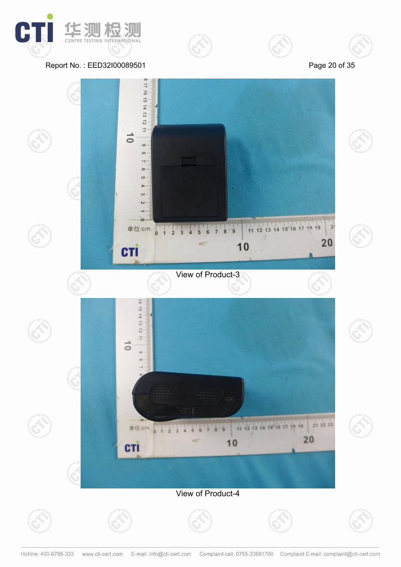
View of Product-3
View of Product-4

Report No. : EED32I00089501 Page 21 of 35
View of Product-5
View of Product-6

Report No. : EED32I00089501 Page 22 of 35
View of Product-7
View of Product-8

Report No. : EED32I00089501 Page 23 of 35
View of Product-9
View of Product-10

Report No. : EED32I00089501 Page 24 of 35
View of Product-11
View of Product-12

Report No. : EED32I00089501 Page 25 of 35
View of Product-13
View of Product-14

Report No. : EED32I00089501 Page 26 of 35
View of Product-15
View of Product-16

Report No. : EED32I00089501 Page 27 of 35
View of Product-17
View of Product-18

Report No. : EED32I00089501 Page 28 of 35
View of Product-19
View of Product-20

Report No. : EED32I00089501 Page 29 of 35
View of Product-21
View of Product-22

Report No. : EED32I00089501 Page 30 of 35
View of Product-23
View of Product-24

Report No. : EED32I00089501 Page 31 of 35
View of Product-25
View of Product-26

Report No. : EED32I00089501 Page 32 of 35
View of Product-27
View of Product-28
Report No. : EED32I00089501 Page 33 of 35
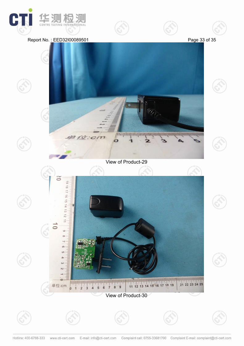
View of Product-29
View of Product-30

Report No. : EED32I00089501 Page 34 of 35
View of Product-31
View of Product-32

Report No. : EED32I00089501 Page 35 of 35
View of Product-33
*** End of Report ***
The test report is effective only with both signature and specialized stamp. The result(s) shown in this
report refer only to the sample(s) tested. Without written approval of CTI, this report can’t be
reproduced except in full.