reporting guide for cisco unified customer voice portal ... · pdf filereporting guide for...
TRANSCRIPT

Reporting Guide for Cisco Unified Customer Voice PortalRelease 4.1(1)
Updated: December 2008
Americas Headquarters
Cisco Systems, Inc.
170 West Tasman Drive
San Jose, CA 95134-1706
USA
http://www.cisco.com
Tel: 408 526-4000
800 553-NETS (6387)
Fax: 408 527-0833
THE SPECIFICATIONS AND INFORMATION REGARDING THE PRODUCTS IN THIS MANUAL ARE SUBJECT TO CHANGE WITHOUT NOTICE.ALL STATEMENTS, INFORMATION, AND RECOMMENDATIONS IN THIS MANUAL ARE BELIEVED TO BE ACCURATE BUT ARE PRESENTEDWITHOUT WARRANTY OF ANY KIND, EXPRESS OR IMPLIED. USERS MUST TAKE FULL RESPONSIBILITY FOR THEIR APPLICATION OFANY PRODUCTS.THE SOFTWARE LICENSE AND LIMITED WARRANTY FOR THE ACCOMPANYING PRODUCT ARE SET FORTH IN THE INFORMATION PACKETTHAT SHIPPED WITH THE PRODUCT AND ARE INCORPORATED HEREIN BY THIS REFERENCE. IF YOU ARE UNABLE TO LOCATE THESOFTWARE LICENSE OR LIMITED WARRANTY, CONTACT YOUR CISCO REPRESENTATIVE FOR A COPY.The Cisco implementation of TCP header compression is an adaptation of a program developed by the University of California, Berkeley (UCB) aspart of UCBs public domain version of the UNIX operating system. All rights reserved. Copyright © 1981, Regents of the University of California.NOTWITHSTANDING ANY OTHER WARRANTY HEREIN, ALL DOCUMENT FILES AND SOFTWARE OF THESE SUPPLIERS ARE PROVIDED"AS IS" WITH ALL FAULTS. CISCO AND THE ABOVE-NAMED SUPPLIERS DISCLAIM ALL WARRANTIES, EXPRESSED OR IMPLIED, INCLUDING,WITHOUT LIMITATION, THOSE OF MERCHANTABILITY, FITNESS FOR A PARTICULAR PURPOSE AND NONINFRINGEMENT OR ARISINGFROM A COURSE OF DEALING, USAGE, OR TRADE PRACTICE.IN NO EVENT SHALL CISCO OR ITS SUPPLIERS BE LIABLE FOR ANY INDIRECT, SPECIAL, CONSEQUENTIAL, OR INCIDENTAL DAMAGES,INCLUDING, WITHOUT LIMITATION, LOST PROFITS OR LOSS OR DAMAGE TO DATA ARISING OUT OF THE USE OR INABILITY TO USETHIS MANUAL, EVEN IF CISCO OR ITS SUPPLIERS HAVE BEEN ADVISED OF THE POSSIBILITY OF SUCH DAMAGES.CCVP, the Cisco logo, and Welcome to the Human Network are trademarks of Cisco Systems, Inc.; Changing the Way We Work, Live, Play, andLearn is a service mark of Cisco Systems, Inc.; and Access Registrar, Aironet, BPX, Catalyst, CCDA, CCDP, CCIE, CCIP, CCNA, CCNP, CCSP,Cisco, the Cisco Certified Internetwork Expert logo, Cisco IOS, Cisco Press, Cisco Systems, Cisco Systems Capital, the Cisco Systems logo, CiscoUnity, Enterprise/Solver, EtherChannel, EtherFast, EtherSwitch, Fast Step, Follow Me Browsing, FormShare, GigaDrive, HomeLink, Internet Quotient,IOS, iPhone, IP/TV, iQ Expertise, the iQ logo, iQ Net Readiness Scorecard, iQuick Study, LightStream, Linksys, MeetingPlace, MGX, Networkers,Networking Academy, Network Registrar, PIX, ProConnect, ScriptShare, SMARTnet, StackWise, The Fastest Way to Increase Your Internet Quotient,and TransPath are registered trademarks of Cisco Systems, Inc. and/or its affiliates in the United States and certain other countries.All other trademarks mentioned in this document or Website are the property of their respective owners. The use of the word partner does not implya partnership relationship between Cisco and any other company. (0710R)Any Internet Protocol (IP) addresses used in this document are not intended to be actual addresses. Any examples, command display output, andfigures included in the document are shown for illustrative purposes only. Any use of actual IP addresses in illustrative content is unintentional andcoincidental.Copyright © 2007 Cisco Systems, Inc. All rights reserved.
Table of Contents
Preface ...........................................................................................................................................................1Purpose .....................................................................................................................................................1Audience ....................................................................................................................................................1Organization ..............................................................................................................................................1Related Documentation .............................................................................................................................2Conventions................................................................................................................................................3Obtaining Documentation, Obtaining Support, and Security Guidelines....................................................4
1. Introduction to the Reporting Server...........................................................................................................5Overview.....................................................................................................................................................5How the Reporting Server Functions.........................................................................................................5
2. Managing the Database..............................................................................................................................9Data Retention.........................................................................................................................................10
Data Categories.......................................................................................................................................12Database Backup.....................................................................................................................................12Retries: Backup and Purge.......................................................................................................................13Database Recovery..................................................................................................................................14
How to Perform a Complete Database Restore...................................................................................14Database Users........................................................................................................................................15
Instance Owner....................................................................................................................................15Database Administrator.......................................................................................................................15Application User...................................................................................................................................15Reporting User....................................................................................................................................15
Failure and Restoration............................................................................................................................16
3. Configuring the Reporting Server.............................................................................................................17Adding a Reporting Server to the Operations Console............................................................................17
Adding a Reporting Server..................................................................................................................18Viewing Device State...........................................................................................................................22
Editing a Reporting Server in the Operations Console.............................................................................22Editing a Reporting Server..................................................................................................................22Guidelines for Choosing Secure Passwords........................................................................................32Uploading a Log Messages XML File..................................................................................................33Downloading a Log Messages XML File.............................................................................................34Editing the Log Messages XML File....................................................................................................35Unified CVP Event Severity Levels......................................................................................................35
Applying a License to a Reporting Server Using the Operations Console...............................................36Applying a License to a Reporting Server...........................................................................................36
Deleting a Reporting Server From the Operations Console.....................................................................37Deleting a Reporting Server................................................................................................................37
Viewing Reporting Statistics.....................................................................................................................38Reporting Server Statistics..................................................................................................................38
Finding a Reporting Server in the Operations Console............................................................................40Finding a Reporting Server..................................................................................................................40
Adding and Removing a Device from a Device Pool................................................................................41Adding or Removing a Device From a Device Pool.............................................................................41
4. Configuring the VXML Server for Reporting..............................................................................................43
Reporting Guide for Cisco Unified Customer Voice Portal Release 4.1(1)
i

Adding a VXML Server to the Operations Console..................................................................................43Adding a VXML Server........................................................................................................................43
Editing a VXML Server in the Operations Console...................................................................................45Editing a VXML Server.........................................................................................................................45VXML Server General Properties........................................................................................................46VXML Server Configuration Properties...............................................................................................47Inclusive and Exclusive VoiceXML Filters for Reporting......................................................................48
Transferring a File to Multiple Devices......................................................................................................50Procedure............................................................................................................................................51Procedure............................................................................................................................................51
5. Introduction to the Database Schema.......................................................................................................53About the Database Schema....................................................................................................................53Entity-Relationship Diagram.....................................................................................................................54Table Definitions.......................................................................................................................................54
ActionTypeRef Table............................................................................................................................55Call Table.............................................................................................................................................55CallEvent Table....................................................................................................................................57CallICMInfo Table.................................................................................................................................57CauseRef Table...................................................................................................................................58CVPDataRetention Table.....................................................................................................................60CVPDateTrap Table..............................................................................................................................61CVPDBSpaceUsed Table....................................................................................................................61CVPDBVersion Table...........................................................................................................................61CVPLog Table......................................................................................................................................62CVPPartitionInfo Table.........................................................................................................................62CVPPartitionParameters Table............................................................................................................62CVPPurgeList Table.............................................................................................................................63ElementTypeRef Table.........................................................................................................................63EventTypeRef Table.............................................................................................................................64OutgoingECCVariable Table................................................................................................................65ResultRef Table....................................................................................................................................65SubSystemTypeRef Table....................................................................................................................66UserInputModeRef Table.....................................................................................................................66VarDataTypeRef Table.........................................................................................................................67VoiceActionTypeRef Table....................................................................................................................67VXMLCustomContent Table.................................................................................................................68VXMLElement Table............................................................................................................................68VXMLElementDetail Table...................................................................................................................69VXMLElementFlag Table.....................................................................................................................70VXMLError Table..................................................................................................................................71VXMLHotEvent Table...........................................................................................................................71VXMLHotLink Table.............................................................................................................................72VXMLSession Table.............................................................................................................................72VXMLSessionVariable Table................................................................................................................73VXMLVoiceInteractDetail Table............................................................................................................74
6. Reporting Against the Database...............................................................................................................75Using the Cisco-Provided Sample Report Templates...............................................................................75
Unified CVP Call Summary Report......................................................................................................76Unified CVP Application Summary Report..........................................................................................77Unified CVP VXML Element By Call Report........................................................................................77
Reporting Guide for Cisco Unified Customer Voice Portal Release 4.1(1)
ii
Unified CVP and Unified ICME Report................................................................................................77Running Crystal Reports Templates....................................................................................................78
7. Reporting Best Practices..........................................................................................................................81CPU Intensive Reports.............................................................................................................................81Filtering Data to be Stored in the Database.............................................................................................82ECC Variable Security..............................................................................................................................82Writing Efficient SQL when Creating Reports..........................................................................................83Database Sizing Issues............................................................................................................................83Database Backup and Recovery..............................................................................................................84Only Use Reporting Users when Querying the Database........................................................................84Informix, Operating System Time, and Local Time...................................................................................84Assuring Accurate Time Stamps for Reporting and Logging....................................................................84Passwords................................................................................................................................................84Joining Data with an ICM HDS Database.................................................................................................85Joining Unified CVP and SQL Server Data..............................................................................................85Reporting Isolation Level..........................................................................................................................85Database Retention Settings....................................................................................................................85Purge and Backup Database Maintenance Tasks....................................................................................85Zero Duration Calls and Writing Reports..................................................................................................86
Index .............................................................................................................................................................87
Reporting Guide for Cisco Unified Customer Voice Portal Release 4.1(1)
iii
List of Figures
Figure 1: CVP Architecture...............................................................................................................................................6
Figure 2: Call Flow..........................................................................................................................................................54
Figure 3: ER Diagram......................................................................................................................................................54
Reporting Guide for Cisco Unified Customer Voice Portal Release 4.1(1)
iv

Preface
Purpose
This document provides information to help you configure and manage the Reporting Server.
Audience
This guide is intended for Call Center managers, Unified Customer Voice Portal (CVP) systemmanagers, Cisco Unified Intelligent Contact Management Enterprise (ICME) and Cisco NetworkApplication Manager (NAM) system managers, VoIP technical experts, and IVR applicationdevelopers. Readers of this guide should already have a general understanding of Unified CVPsoftware. Readers should be familiar with general Unified CVP installation and setup procedures.
Organization
This guide is divided into the following chapters:
DescriptionChapter
Provides an introductory discussion of the Reporting Server.Chapter 1, "Introduction to the Reporting Server" (page 5)
Discusses concepts to be kept in mind while managing thedatabase.
Chapter 2, "Managing the Database" (page 9)
Discusses how to configure the Reporting Server using theOperations Console.
Chapter 3, "Configuring the Reporting Server" (page 17)
Discusses how to configure the VXML Server using theOperations Console.
Chapter 4, "Configuring the VXML Server for Reporting"(page 43)
Reporting Guide for Cisco Unified Customer Voice Portal Release 4.1(1)
1

DescriptionChapter
Provides information about the database schema.Chapter 5, "Introduction to the Database Schema" (page53)
Discusses generating reports.Chapter 6, "Reporting Against the Database" (page 75)
Provides a list of best practices.Chapter 7, "Reporting Best Practices" (page 81)
Related Documentation
Unified CVP provides the following documentation:
• Cisco Security Agent Installation/Deployment for Cisco Unified Customer Voice Portalprovides installation instructions and information about Cisco Security Agent for the UnifiedCVP deployment. We strongly urge you to read this document in its entirety.
• Configuration and Administration Guide for Cisco Unified Customer Voice Portal describeshow to set up, run, and administer the Cisco Unified CVP product, including associatedconfiguration.
• Element Specifications for Cisco Unified Call Services, Universal Edition and Unified CallStudio describes the settings, element data, exit states, and configuration options for Elements.
• Installation and Upgrade Guide for Cisco Unified Customer Voice Portal describes how toinstall Unified CVP software, perform initial configuration, and upgrade.
• Operations Console Online Help for Cisco Unified Customer Voice Portal describes howto use the Operations Console to configure Unified CVP solution components.
• Planning Guide for Cisco Unified Customer Voice Portal provides a product overview anddescribes how to plan for a Unified CVP deployment.
• Port Utilization Guide for Cisco Unified Customer Voice Portal describes the ports used ina Unified CVP deployment.
• Programming Guide for Cisco Unified Call Services, Universal Edition and Unified CallStudio describes how to build components that run on the Cisco Unified CVP VXML Server.
• Say It Smart Specifications for Cisco Unified Call Services, Universal Edition and CiscoUnified Call Studio describes in detail the functionality and configuration options for all SayIt Smart plugins included with the software.
• Troubleshooting Guide for Cisco Unified Customer Voice Portal describes how to isolateand solve problems in the Unified CVP solution.
• User Guide for Cisco Unified Call Services, Universal Edition and Cisco Unified Call Studiodescribes the functionality of Call Studio including creating projects, using the Call Studioenvironment, and deploying applications to the Cisco Unified CVP VXML Server.
Reporting Guide for Cisco Unified Customer Voice Portal Release 4.1(1)
2
Preface
Related Documentation

For additional information about Unified ICME, see the Cisco web site (http://www.cisco.com/en/US/products/sw/custcosw/ps1001/tsd_products_support_series_home.html) listingUnified ICME documentation.
Conventions
This manual uses the following conventions:
DescriptionConvention
Boldface font is used to indicate commands,such as user entries, keys, buttons, and folderand submenu names. For example:
boldface font
• Choose Edit > Find.
• Click Finish.
Italic font is used to indicate the following:italic font
• To introduce a new term. Example: A skillgroup is a collection of agents who sharesimilar skills.
• For emphasis. Example: Do not use thenumerical naming convention.
• A syntax value that the user must replace.Example: IF (condition, true-value,false-value)
• A book title. Example: See the Cisco CRSInstallation Guide.
Window font, such as Courier, is used for thefollowing:
window font
• Text as it appears in code or that the windowdisplays. Example: <html><title>CiscoSystems,Inc. </title></html>
Angle brackets are used to indicate thefollowing:
< >
• For arguments where the context does notallow italic, such as ASCII output.
• A character string that the user enters butthat does not appear on the window such asa password.
Reporting Guide for Cisco Unified Customer Voice Portal Release 4.1(1)
3
Preface
Conventions

Obtaining Documentation, Obtaining Support, and Security Guidelines
For information on obtaining documentation, obtaining support, providing documentationfeedback, security guidelines, and also recommended aliases and general Cisco documents, seethe monthly What's New in Cisco Product Documentation, which also lists all new and revisedCisco technical documentation, at:
http://www.cisco.com/en/US/docs/general/whatsnew/whatsnew.html
Reporting Guide for Cisco Unified Customer Voice Portal Release 4.1(1)
4
Preface
Obtaining Documentation, Obtaining Support, and Security Guidelines
Introduction to the Reporting ServerThis section contains the following topics:
• Overview, page 5• How the Reporting Server Functions, page 5
Overview
The Reporting Server houses the Reporting Service, and hosts an IBM Informix Dynamic Server(IDS) database management system.
The Reporting Service provides historical reporting to a distributed self-service deployment ina call center environment. The system is used to assist call center managers with call activitysummary information to manage daily operations. It can also provide operational detail data forvarious IVR applications.
The Reporting Service receives reporting data from the IVR Service, the SIP Service (if used),and the VXML Server. As stated, it is deployed together with an Informix database managementsystem, and it transforms and writes this reporting data into that database. The database schemais prescribed by the Unified Customer Voice Portal (CVP) product, but the schema is fullypublished so that customers may develop custom reports based on it.
The Reporting Service does not itself perform database administrative and maintenance activitiessuch as backups or purges. However, Unified CVP provides access to such maintenance tasksthrough the Operations Console.
How the Reporting Server Functions
The diagram below shows the Unified CVP architecture.
Reporting Guide for Cisco Unified Customer Voice Portal Release 4.1(1)
5
Chapter 1

Figure 1: CVP Architecture
Note:
• The Reporting Service and the Database are separated merely for functional clarity. Togetherthey comprise the Reporting Server.
• The connection of the Operations Console to the Call Server, through an OAMP ResourceManager (ORM) is simply indicative. An ORM is co-located with each managed UnifiedCVP component, and the Operations Console is connected to each component. The ORM isinvisible to the end-user.
A Call Server is a physical machine on which resides, for example, the IVR Service, the SIPService, and the ICM Service. The Call Server uses a central messaging bus to allow each serviceto communicate. The Reporting Service connects to the message bus either through an in-processplug-in or an out-of-process plug-in depending on whether the Reporting Service resides in thesame JVM with the message bus system. It listens to all the messages passing through themessage bus and captures call-state change messages sent from SIP or IVR services or reportingmessages from a VXML Server.
The Reporting Service then parses those messages and converts them into batches of appropriateSQL statements and executes them into a SQL database using the Java Database Connectivity(JDBC) API. The Reporting Service can also receive and process Unified CVP admin messagesto perform Unified CVP system administrative tasks, such as turning on or off debugging,querying statistics, and so forth. As the diagram shows, the Reporting Service can be shared bymultiple Call Servers that belong to the same Unified CVP deployment.
Note: There only needs to be one Reporting Server in a deployment. During temporary databaseoutages, messages are buffered to file and inserted into the database when the database comesback on-line. The amount of time that messages can be buffered depends on the systemthroughput.
If more than one Reporting Server is used, be aware that:
• Each Call Server and each VXML Server can be associated with only one Reporting Server
• Reports cannot span multiple Informix databases
Reporting Guide for Cisco Unified Customer Voice Portal Release 4.1(1)
6
Chapter 1: - Introduction to the Reporting Server
How the Reporting Server Functions

A third-party reporting engine, such as Crystal Reports, can be used to generate various reportsagainst the predefined Unified CVP database schema. Unified CVP provides a few sampleCrystal report templates to demonstrate how to use Unified CVP data stored in Unified CVPdatabase tables. See Chapter 6, "Reporting Against the Database" (page 75) for a descriptionof the templates.
Reporting Guide for Cisco Unified Customer Voice Portal Release 4.1(1)
7
Chapter 1: Introduction to the Reporting Server
How the Reporting Server Functions

Reporting Guide for Cisco Unified Customer Voice Portal Release 4.1(1)
8
Chapter 1: - Introduction to the Reporting Server
How the Reporting Server Functions
Managing the DatabaseThe Reporting Service does not itself perform database administrative and maintenance activitiessuch as backups or purges. However, Unified CVP provides access to such maintenance tasksthrough the Operations Console.
Caution: The management of database and reporting users must be done using theOperations Console. This ensures that all dependencies are synchronized. The changingof passwords outside of this tool could result in the Reporting Server not being able toconnect to the database.
These same conditions will arise if passwords expire. If you implement a passwordexpiration policy, then ensure that you remember to use the Operations Console to changethe Informix, Database Administrator, and Database Users (see "Database Users" (page15)) passwords before the passwords expire to avoid the possibility of data loss and/ordowntime.
It will be useful to familiarize yourself with the database management concepts discussed inthis chapter.
Note: The following maintenance tasks are supported by Unified CVP: database backups anddata purges. Database backup and purge cannot run at the same time. Purge should be scheduledat least 3 hours before a backup. These jobs, as well as on-demand backup, should be run atlow call and reporting volume times. From the perspective of Unified CVP, database backupsare optional, data purges are mandatory. However, from the perspective of the user, databasebackups should not be considered optional. See the discussion below.
The database backup and purge maintenance tasks are created as Windows Scheduled Tasks,and can be viewed in the Scheduled Tasks window (Start > Programs > Accessories > SystemTools > Scheduled Tasks). Periodically, you should check the Scheduled Tasks to ensure theLast Run Time was as expected and there are no status messages.
This section contains the following topics:
• Data Retention, page 10
Reporting Guide for Cisco Unified Customer Voice Portal Release 4.1(1)
9
Chapter 2

• Data Categories, page 12• Database Backup, page 12• Retries: Backup and Purge, page 13• Database Recovery, page 14• Database Users, page 15• Failure and Restoration, page 16
Data Retention
Via the Operations Console, users are able to select the time of day to run database purge, andto set the number of days of data to be retained by data category. During schema creation, defaultdata retention values are specified for each data category. Note that a high level category, suchas Call, cannot have a lower retention time than a dependent category, such as Call Event.
Note: When you schedule a purge from the Operations Console, two Windows jobs are scheduledon the Reporting Server. The time that you choose is used to schedule what is referred to as the"Nightly purge" job. The other job is referred to as the "Midday purge" and is automaticallyscheduled 12 hours from the Nightly purge. So, for example, if you schedule a purge at 2 A.M.,then the Nightly purge is run at 2 A.M. and the Midday purge at 2 P.M.
• The Nightly purge performs a purge if necessary (as required by a data retention value, orfor an emergency purge—see below), in addition to other tasks like updating the databasestatistics. If a purge is performed, the statistics are updated after the purge. In addition, onSundays, the Nightly purge also copies the Informix log file to a backup directory, creates anew log file and deletes the old. The Nightly purge should be scheduled at a time of low calland reporting volume.
• The Midday purge only performs a purge, and only if necessary. Even if a purge occurs, thisprocess is not system intensive in the same way that the Nightly purge is.
• During a purge, reporting users may be disconnected from the database, if they are holdinglocks that contend with purge. Notify reporting users not to run reports at this time.
If the number of days of data that you chose to retain cannot be contained within the database,then the database will 'emergency' purge old data to create space for new data. Emergency purgeis, therefore, a critical safety mechanism for Unified CVP. If used space has grown past thesystem's high water mark, the user will be notified by an SNMP trap message and data will bepurged. The SNMP notification will alert the user to the loss of data and request that they shrinktheir 'retention days' data settings. Users should reduce the number of actual days of data retaineduntil emergency purge is no longer required. Additionally, users can reduce the data generatedby means of data filters (for VXML Server application detail data filtering, see Chapter 4,"Configuring the VXML Server for Reporting" (page 43)).
During a database purge operation, the Reporting Server disconnects from the database (thoughfor no more than 10 minutes) and starts buffering messages in memory until the purge is done.The same memory limitations as described in the section "Failure and Restoration" (page 16)apply.
Reporting Guide for Cisco Unified Customer Voice Portal Release 4.1(1)
10
Chapter 2: - Managing the Database
Data Retention
This page is intentionally left blank.
Reporting Guide for Cisco Unified Customer Voice Portal Release 4.1(1)
11
Chapter 2: Managing the Database
Data Categories
The following data categories exist for Unified CVP. Note that a high level category, such asCall, cannot have a lower retention time than a dependent category, such as CallEvent. For eachcategory, the default data retention times, in days, is given within parentheses.
level 1: Call (30)
level 2: -Call Event (30)
level 2: -VoiceXML Session (30)
level 3: --VoiceXML Element (15)
level 4: ---VoiceXML ECC Variable (15)
level 4: ---VoiceXML Interact Detail (15)
level 4: ---VoiceXML Session Variable (15)
level 4: ---VoiceXML Element Detail (15)
Database Backup
Unified CVP allows users to turn the scheduling of data backups on or off, as well as to runbackups on-demand. Backups are made to the Reporting Servers' local file system. By default,scheduled backups are turned off.
Caution: Unified CVP backup scheduling is an optional feature. Backup is the responsibilityof the user. Data loss may occur if the backing up of files is not managed appropriatelyby the user.
If Unified CVP backup scheduling is turned on, the backup frequency is once per day. Backupsshould be scheduled to run no sooner than 3 hours after the scheduled purge job.
Additionally, users can run a backup on demand—as long as another backup, or a purge, is notalready running. All database backups are performed and stored on the local machine. Due tospace limitations, a maximum of two backups and a minimum of one backup will be availableat any time on the local machine. Having two files is critical. If the system was to fail whilewriting a backup, and the failure was such that a restore is necessary, the older backup file wouldbe required for restore.
It is a best practice to:
• Keep a given backup for at least two weeks
• Check the integrity of the backup periodically
Reporting Guide for Cisco Unified Customer Voice Portal Release 4.1(1)
12
Chapter 2: - Managing the Database
Data Categories

Unified CVP uses the Informix backup utility ontape (for both backup and restore).
Unified CVP names backup files as follows. When a new backup launches—either scheduled,or on demand from the Operations Console—the new file is named cvp_backup_data. TheUnified CVP backup script has been written to first copy the last backup file cvp_backup_datato cvp_backup_data.old. This always leaves two backup files on the local system and makes iteasy for Unified CVP administrators to script copy jobs to move the files. The backup scriptensures that two backups cannot be launched at the same time.
Note: The backup script also ensures that a backup cannot be launched if a purge is underway,and vice versa.
Storing a backup on the local machine does not protect against failure of that machine or lossof a site. Cisco strongly recommends that customers manually or automatically create a job tocopy the cvp_backup_data.old file to a separate machine, preferably at a separate location.Again, the user is responsible for managing backup data.
Note: Only the cvp_backup_data.old file can be copied. The cvp_backup_data file can notbe copied. Attempting to copy the cvp_backup_data file will lock the file and prevent anotherbackup from running.
For information on configuring backups, see Chapter 3, "Configuring the Reporting Server"(page 17).
Retries: Backup and Purge
Occasionally, a backup or purge cannot run when scheduled. For example, if an on-demandbackup is running when a purge is scheduled to run, the purge will be prevented from running.
Retries of scheduled backups or purges are performed according to the following rules.
Note: There are no retries for an on-demand backup.
• A scheduled backup retries every 10 minutes, for up to 4 hours.
• A purge retries every 10 minutes, for up to 6 hours.
• At the end of 4 hours (for a backup) or 6 hours (for a purge), if the operation has not succeeded,retries stop and an SNMP alert is sent.
• If both a backup and a purge are retrying simultaneously, there is no guarantee as to whichoperation will run first.
• If a lock (the mechanism preventing a backup or purge from running) is over 12 hours old,the system clears it.
Reporting Guide for Cisco Unified Customer Voice Portal Release 4.1(1)
13
Chapter 2: Managing the Database
Retries: Backup and Purge

Database Recovery
Unified CVP database recovery returns the database to the state of the most recent completebackup. For example, if the user schedules a backup at 01:00 and restores the database at 23:00,the same day, the restored database is in the state it was in at 01:00.
Even though the Reporting Server can operate in partial mode, if the database is offline, Ciscorecommends stopping the Reporting Server during a database restore to ensure the database isable to control all system resources to minimize the time it takes to complete the database restore.
Note: Data loss will occur if the Reporting Server is turned off and the message bus exceedsits temporary persistence capabilities.
Caution: Prior to and following a database restore, the following steps must be performed:
1. Before the restore, disable scheduled tasks (backup, purge).
2. After the restore, re-enable scheduled tasks.
How to Perform a Complete Database Restore
The following task effects a complete restore of the full database if performed on the originaldatabase server. It assumes that the backup was performed through Unified CVP.
Step 1 Go to Windows Services and stop the Informix IDS Service
Step 2 At the command line type: ontape –r
Step 3 Answer the prompts with the following answers:
a. Continue Restore? y
b. Do you want to back up the logs? n
c. Restore a level 1 archive? n
d. Do you want to restore log tapes? n
Step 4 After the program terminates, wait at least 5 minutes. At the command prompt, check the statusof Informix by typing : onstat -
a. If it returns 'IBM Informix Dynamic Server Version 10.00.xxx-- Fast Recovery…' thenwait another 5 minutes and recheck the status by typing: onstat -(10.00.xxx where xxx isthe database subversion number).
Reporting Guide for Cisco Unified Customer Voice Portal Release 4.1(1)
14
Chapter 2: - Managing the Database
Database Recovery

b. If it returns 'IBM Informix Dynamic Server Version 10.00.xxx -- Quiescent…', changethe database to multiuser mode by typing: onmode -m then wait 2 minutes, and recheckthe status by typing: onstat –
c. If it returns 'IBM Informix Dynamic Server Version 10.00.xxx -- On-Line', the databaseis ready to support the Unified CVP application
Database Users
Unified CVP defines four categories of database users. The four categories are instance owner(informix), database administrator, application user, and reporting user.
Instance Owner
During the Unified CVP installation, a user named informix is created. This user owns theInformix instance and can run the IDS service. This account should never be used to access theUnified CVP database.
Database Administrator
The cvp_dbadmin user will create, update, and own the database. This account should not beused to run the database or to run reports against the system.
The cvp_dbadmin user can create and delete reporting users and perform database administrativeactivities, such as purge and backup.
Application User
The Unified CVP JDBC uses cvp_dbuser to access the Informix database. This user has therights to connect, insert, update, and delete records in the Unified CVP database. If this user'spassword expires, then data insertion and purge will fail. This could result in data loss.
Reporting User
Reporting users are created and deleted by a database administrator using the Operations Console.Multiple reporting users are allowed. Reporting users have read-only access to the Unified CVPdatabase.
Only reporting users should be allowed to generate reports. As stated previously, reporting usershave read-only database access; therefore, they cannot accidentally modify the database schemaor database data.
Reporting Guide for Cisco Unified Customer Voice Portal Release 4.1(1)
15
Chapter 2: Managing the Database
Database Users

Failure and Restoration
• If the Reporting Server fails, messages destined for the Reporting Server are buffered by theCall Server, in memory, up to 200,000 messages. After that limit is reached, all new messagesare dropped.
• If the database connection fails, the Reporting Server sends out an SNMP alert and startspersisting messages to a file, up to a user specified limit. During this time the ReportingServer stays In Service. When 75% of the specified limit is reached, a warning is written tothe log file. Once 100% of the limit is reached, an SNMP alert is sent out and the ReportingServer goes into Partial Service—any new messages may be dropped.
When the database connection comes back up, the Reporting Server goes into recovery modeand changes its state to Partial Service if it is not in that state already. It then starts readingmessages from the file and committing them to the database. Depending on the size of thefile, it may take a long time (sometimes hours) to commit all of the data to the database. Anynew messages that come in during recovery will be buffered in memory. There is, however,a limit to the number of messages that the Reporting Server can buffer. This is true regardlessof the mode or state it is in. When the number of buffered messages reaches 100,000, anSNMP alert is sent out to warn the user. At 200,000 another SNMP alert is sent out and allnew messages' detail information is dropped—keeping only basic data like call, call event,and session information. Also at 200,000, the Reporting Server changes its state to PartialService, if it is not already in that state. After the total number of buffered messages reaches300,000, another SNMP alert is sent out and all new messages are dropped from that pointforward.
When the number of messages in memory drops back below 50,000, an SNMP alert is sentout stating that the queue size is back to normal, and the Reporting Server’s state goes backto In Service.
• If, on startup, a persistent file exists, the Reporting Server stays in Partial Service and goesinto recovery mode as described above.
• During a database purge operation, the Reporting Server disconnects from the database andstarts buffering messages in memory until the purge is done. The same memory limitationsas described above apply in this case as well.
Caution: When the Reporting Server is in Partial Service, there are no guarantees thatnew messages will be kept and committed to the database. They will be buffered in memoryfor as much as possible, but at some point they may be dropped either partially or fully.
Reporting Guide for Cisco Unified Customer Voice Portal Release 4.1(1)
16
Chapter 2: - Managing the Database
Failure and Restoration
Configuring the Reporting ServerYou can configure and manage the Reporting Server using the Unified CVP Operations Console,a web-based interface from which you can configure the Unified CVP components in the UnifiedCVP solution. From the Device Management menu, Reporting Server option, you can configureone or more Reporting Servers.
Reporting provides historical reporting to a distributed self-service deployment in a call center.The Reporting Server receives reporting data from one or more Call Servers and VXML servers,and stores that data in an Informix database. Call data is stored in a relational database, on whichyou can write custom reports. Administrators can use the Operations Console to schedule datapurge and database backups. Multiple Call Servers can send data to a single Reporting Server.
You can use third-party reporting tools, such as, Crystal Reports to generate and view reportson call data. Unified CVP provides four sample Crystal report templates. One of the includedtemplates provides an example of joining Unified CVP and Unified ICME.
This section contains the following topics:
• Adding a Reporting Server to the Operations Console, page 17• Editing a Reporting Server in the Operations Console, page 22• Applying a License to a Reporting Server Using the Operations Console, page 36• Deleting a Reporting Server From the Operations Console, page 37• Viewing Reporting Statistics, page 38• Finding a Reporting Server in the Operations Console, page 40• Adding and Removing a Device from a Device Pool, page 41
Adding a Reporting Server to the Operations Console
Adding a Reporting Server to the Operations Console adds its configuration to the OperationsConsole database and adds it to the list of Reporting Servers in the Control Panel. When youadd a Reporting Server, you must associate it with one or more Call Servers. Call data for all
Reporting Guide for Cisco Unified Customer Voice Portal Release 4.1(1)
17
Chapter 3

SIP, H.323, and VoiceXML calls handled by the Call Servers is stored in the Reporting Database.You can also add the server to one or more logical groups of devices, called device pools.
Adding a Reporting Server
Create a new Reporting Server either by using an existing Reporting Server configuration as atemplate or by filling in its values from scratch.
Before You Begin
You must configure the Call Server to associate with the Reporting Server before configuringthe Reporting Server.
Collect the following information about the Reporting Server and Reporting Database duringthe installation of Unified CVP software:
Information Needed:
• Host name of the Call Server associated with the Reporting Server
• Host name and IP address of the server on which the Reporting Database resides
• The Reporting password that was entered during installation
Procedure
To add a Reporting Server:
Step 1 Choose Device Management > CVP Reporting Server.
A window listing Reporting Servers opens.
Note: To use an existing Reporting Server as a template for creating the new Reporting Server,select the Reporting Server by clicking the radio button preceding it and then click Use AsTemplate.
Step 2 Click Add New.
The Reporting Server Configuration window opens to the General Tab.
Step 3 Enter the IP Address and Hostname for the Reporting server and any other desired information.
Step 4 Associate one or more Call Servers to the Reporting server by selecting a Call Server listed inthe Available pane and clicking the right arrow to add it to the Selected pane.
Step 5 Select the Reporting Properties tab and configure reporting properties.
Step 6 Optionally, select the Device Pool tab and add the Reporting Server to a device pool.
Reporting Guide for Cisco Unified Customer Voice Portal Release 4.1(1)
18
Chapter 3: - Configuring the Reporting Server
Adding a Reporting Server to the Operations Console

Step 7 Optionally, select the Infrastructure tab and configure log file and syslog settings.
Step 8 When you finish configuring the Reporting Server:
a. click Save to save the settings in the Operations Server database
b. Or click Save & Deploy to save the settings in the Operations Server database and deploythe changes to the Reporting Server
See Also
Deleting a Reporting Server (page 37)
Editing a Reporting Server (page 22)
Reporting Server General Tab Configuration Settings (page 19)
Reporting Server Properties Tab Configuration Settings (page 20)
Adding and Removing a Device from a Device Pool (page 41)
Reporting Server Infrastructure Settings (page 20)
Viewing Device State (page 22)
Configuring General Reporting Server Information
You can configure settings that identify the Reporting server, associate it with one or more CallServers, and enable or disable security on the General Tab.
Table 1: Reporting Server General Tab Configuration Settings
RangeDefaultDescriptionField
General
Valid IP addressNoneThe IP address of the Reporting serverIP Address
Valid DNS name, whichcan include letters in the
NoneThe host name of the Reporting servermachine
Hostname
alphabet, the numbers 0through 9
Up to 1,024 charactersNoneAn optional text description for theReporting server
Description
On or OffOffSelect to enable secure communicationsbetween the Operations Server and this
Enable SecureCommunication with theOperations Console component. The Reporting Server is
accessed using SSH and files are transferredusing HTTPS.
Reporting Guide for Cisco Unified Customer Voice Portal Release 4.1(1)
19
Chapter 3: Configuring the Reporting Server
Adding a Reporting Server to the Operations Console
RangeDefaultDescriptionField
You must configure secure communicationsbefore you enable this option. See Chapter6 in the Configuration and AdministrationGuide for Unified Customer Voice Portal.
A given Call Server canonly be associated withone Reporting Server.
NoneSelect one or more Call Servers to associatewith the Reporting Server. You must selectat least one Call Server. Call data for all SIP,
Associate Call Servers
H.323, and VoiceXML calls handled by thisCall Server will be stored in the ReportingDatabase. Click the right arrow to add a CallServer to the Selected pane.
Click the left arrow to remove a Call Serverfrom the Selected pane.
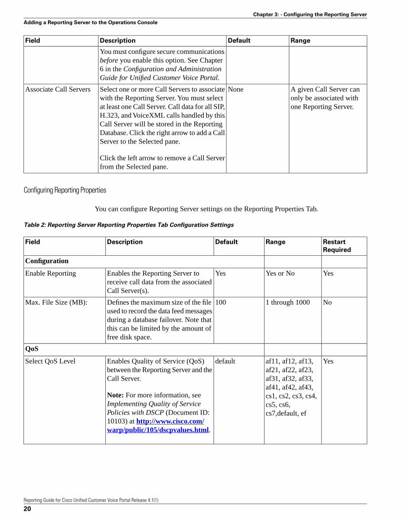
Configuring Reporting Properties
You can configure Reporting Server settings on the Reporting Properties Tab.
Table 2: Reporting Server Reporting Properties Tab Configuration Settings
Restart
Required
RangeDefaultDescriptionField
Configuration
YesYes or NoYesEnables the Reporting Server toreceive call data from the associatedCall Server(s).
Enable Reporting
No1 through 1000100Defines the maximum size of the fileused to record the data feed messages
Max. File Size (MB):
during a database failover. Note thatthis can be limited by the amount offree disk space.
QoS
Yesaf11, af12, af13,af21, af22, af23,
defaultEnables Quality of Service (QoS)between the Reporting Server and theCall Server.
Select QoS Level
af31, af32, af33,af41, af42, af43,
Note: For more information, seeImplementing Quality of Service
cs1, cs2, cs3, cs4,cs5, cs6,cs7,default, efPolicies with DSCP (Document ID:
10103) at http://www.cisco.com/warp/public/105/dscpvalues.html.
Reporting Guide for Cisco Unified Customer Voice Portal Release 4.1(1)
20
Chapter 3: - Configuring the Reporting Server
Adding a Reporting Server to the Operations Console
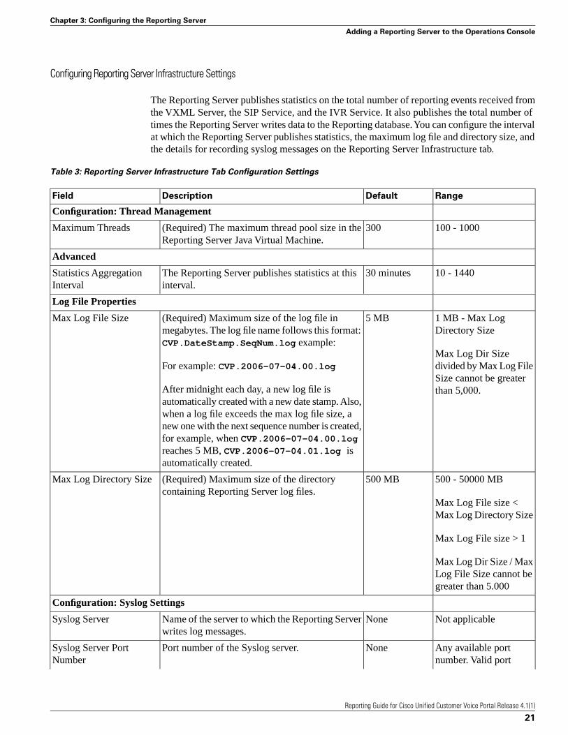
Configuring Reporting Server Infrastructure Settings
The Reporting Server publishes statistics on the total number of reporting events received fromthe VXML Server, the SIP Service, and the IVR Service. It also publishes the total number oftimes the Reporting Server writes data to the Reporting database. You can configure the intervalat which the Reporting Server publishes statistics, the maximum log file and directory size, andthe details for recording syslog messages on the Reporting Server Infrastructure tab.
Table 3: Reporting Server Infrastructure Tab Configuration Settings
RangeDefaultDescriptionField
Configuration: Thread Management
100 - 1000300(Required) The maximum thread pool size in theReporting Server Java Virtual Machine.
Maximum Threads
Advanced
10 - 144030 minutesThe Reporting Server publishes statistics at thisinterval.
Statistics AggregationInterval
Log File Properties
1 MB - Max LogDirectory Size
5 MB(Required) Maximum size of the log file inmegabytes. The log file name follows this format:CVP.DateStamp.SeqNum.log example:
Max Log File Size
Max Log Dir Sizedivided by Max Log FileFor example: CVP.2006-07-04.00.logSize cannot be greaterthan 5,000.After midnight each day, a new log file is
automatically created with a new date stamp. Also,when a log file exceeds the max log file size, anew one with the next sequence number is created,for example, when CVP.2006-07-04.00.logreaches 5 MB, CVP.2006-07-04.01.log isautomatically created.
500 - 50000 MB500 MB(Required) Maximum size of the directorycontaining Reporting Server log files.
Max Log Directory Size
Max Log File size <Max Log Directory Size
Max Log File size > 1
Max Log Dir Size / MaxLog File Size cannot begreater than 5.000
Configuration: Syslog Settings
Not applicableNoneName of the server to which the Reporting Serverwrites log messages.
Syslog Server
Any available portnumber. Valid port
NonePort number of the Syslog server.Syslog Server PortNumber
Reporting Guide for Cisco Unified Customer Voice Portal Release 4.1(1)
21
Chapter 3: Configuring the Reporting Server
Adding a Reporting Server to the Operations Console

RangeDefaultDescriptionField
numbers are integersbetween 1 and 65535.
Not applicableNoneName of a backup server to which the ReportingServer writes log messages.
Backup Server
Any available portnumber. Valid port
NonePort number of the backup Syslog server.Backup Server PortNumber
numbers are integersbetween 1 and 65535.
Viewing Device State
When you select a device from the Device Management menu, the following information islisted about all devices of that type that have been added to the Operations Console:
Device Information:
• Hostname - The host name of the device.
• IP Address - The IP address of the device.
• Device state - A device can be in one of two states: configured or invalid. A configurationcan become invalid if the device is reinstalled. To clear this state, edit the device and clickSave & Deploy. For other possible causes and solutions, refer to the Troubleshooting Guidefor Cisco Unified Customer Voice Portal.
• Description - An optional text description for the device.
Editing a Reporting Server in the Operations Console
You can change the properties of a Reporting Server that has been added to the OperationsConsole. In edit mode, the Database Administration and File Transfer menus are also available.From the Database Administration menu, you can manage reporting users, run database backups,configure database purge, and view database details. From the File Transfer menu, you cantransfer one license file at a time to the Operations Console and then apply that license to aReporting Server. You can also transfer the Log Messages XML file between the OperationsConsole and the Reporting Server.
Editing a Reporting Server
Procedure
To edit a Reporting Server:
Reporting Guide for Cisco Unified Customer Voice Portal Release 4.1(1)
22
Chapter 3: - Configuring the Reporting Server
Editing a Reporting Server in the Operations Console

Step 1 Choose Device Management > CVP Reporting Server.
The Find, Add, Delete, Edit Reporting Servers window opens.
Step 2 Select a Reporting Server by clicking on the link in its name field or by clicking the radio buttonpreceding it and then clicking Edit.
The Edit Reporting Server Configuration window opens.
Step 3 If you have not already applied a license, select File Transfer in the toolbar and then clickLicensing.
The File Transfer page displays.
Step 4 On the General Tab, change the desired general information. You cannot change the IP addressor hostname of the Reporting Server.
Step 5 Select the Reporting Properties Tab, then configure reporting properties.
Step 6 Optionally, select the Device Pool tab and add the Reporting Server to a device pool.
Step 7 Optionally, select the Infrastructure tab and configure log file and syslog settings.
Step 8 When you finish configuring the Reporting Server:
a. click Save to save the settings in the Operations Server database
b. OR click Save & Deploy to save the settings in the Operations Server database and deploythe changes to the Reporting Server
See Also
Deleting a Reporting Server (page 37)
Adding a Reporting Server (page 18)
Configuring Reporting Properties (page 20)
Adding and Removing a Device from a Device Pool (page 41)
Finding a Reporting Server (page 40)
Viewing Device State (page 22)
Reporting Guide for Cisco Unified Customer Voice Portal Release 4.1(1)
23
Chapter 3: Configuring the Reporting Server
Editing a Reporting Server in the Operations Console

Changing a Reporting Database User Password
The Unified CVP installation procedure creates the following three user accounts and sets aninitial password for each account. You can change passwords from the Reporting Server screenin edit mode, but you can only change one user password at a time.
• Informix User (Instance Owner) - Starts and stops the Reporting database, using Informixtools.
• Unified CVP Database Administrator - Uses the Operations Console to run backups, schedulepurges, check database used space, and add and remove Reporting users.
• Unified CVP Database User (Application User) - Connects, inserts, and updates records inthe Informix database. This user cannot modify the Reporting schema.
Procedure
To change a reporting database user password:
Step 1 Choose Device Management > CVP Reporting Server.
The Find, Add, Delete, Edit Reporting Servers window opens.
Step 2 Select the Reporting Server to edit by clicking the link to its name under the Hostname column.
Step 3 Click Edit.
The Edit Reporting Server Configuration window opens with the current settings displayed.
Step 4 Select the Database Administration menu in the toolbar, then select Change User Passwords.
The Reporting Server: Change User Passwords page opens, displaying the IP address and hostname for the currently selected Reporting Server.
Step 5 In the User field, use the drop-down menu to select the user whose password you want to change.
Step 6 In Old Password field, enter the existing password for that user.
Step 7 In the New Password field, enter the new password.
Note: Passwords must follow guidelines for secure passwords.
Step 8 In the Reconfirm Password field, retype the new password.
Step 9 Click Save & Deploy to save the changes to the Operations Console database and deploy themto the Reporting Server.
Reporting Guide for Cisco Unified Customer Voice Portal Release 4.1(1)
24
Chapter 3: - Configuring the Reporting Server
Editing a Reporting Server in the Operations Console
See Also
Running Reporting Database Backups (page 27)
Configuring Reporting Database Purge (page 29)
Managing Reporting Users (page 25)
Guidelines for Choosing Secure Passwords (page 32)
Viewing Reporting Database Details (page 31)
Getting Reporting Server Statistics (page 39)
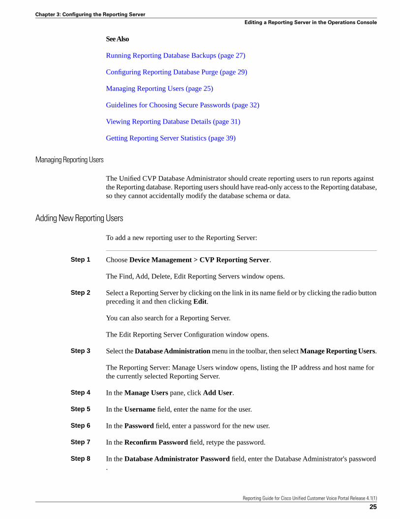
Managing Reporting Users
The Unified CVP Database Administrator should create reporting users to run reports againstthe Reporting database. Reporting users should have read-only access to the Reporting database,so they cannot accidentally modify the database schema or data.
Adding New Reporting Users
To add a new reporting user to the Reporting Server:
Step 1 Choose Device Management > CVP Reporting Server.
The Find, Add, Delete, Edit Reporting Servers window opens.
Step 2 Select a Reporting Server by clicking on the link in its name field or by clicking the radio buttonpreceding it and then clicking Edit.
You can also search for a Reporting Server.
The Edit Reporting Server Configuration window opens.
Step 3 Select the Database Administration menu in the toolbar, then select Manage Reporting Users.
The Reporting Server: Manage Users window opens, listing the IP address and host name forthe currently selected Reporting Server.
Step 4 In the Manage Users pane, click Add User.
Step 5 In the Username field, enter the name for the user.
Step 6 In the Password field, enter a password for the new user.
Step 7 In the Reconfirm Password field, retype the password.
Step 8 In the Database Administrator Password field, enter the Database Administrator's password.
Reporting Guide for Cisco Unified Customer Voice Portal Release 4.1(1)
25
Chapter 3: Configuring the Reporting Server
Editing a Reporting Server in the Operations Console

Step 9 Click Add to add the user.
See Also
Changing Reporting User Passwords (page 26)
Removing Reporting Users (page 27)
Changing Reporting Database User Passwords (page 23)
Finding a Reporting Server (page 40)
Changing a Reporting User's Password
To change a reporting user's password:
Step 1 Choose Device Management > CVP Reporting Server.
The Find, Add, Delete, Edit Reporting Servers window opens.
Step 2 Select a Reporting Server by clicking on the link in its name field or by clicking the radio buttonpreceding it and then clicking Edit.
You can also search for a Reporting Server.
The Edit Reporting Server Configuration window opens.
Step 3 Select the Database Administration menu in the toolbar, then select Manage Reporting Users.
The Reporting Server: Manage Users window opens, listing the IP address and host name forthe currently selected Reporting Server.
Step 4 In the Manage Users pane, click Change Password.
Step 5 From the Available users list, select the user whose password you want to change and clickthe left arrow. The user name will appear in Username field.
Step 6 In the Old Password field, enter the user's original password.
Step 7 In the New Password field, enter the new password.
Step 8 In the Reconfirm Password field, retype the new password.
Step 9 Click Change to make the change.
See Also
Changing Reporting Database User Passwords (page 23)
Reporting Guide for Cisco Unified Customer Voice Portal Release 4.1(1)
26
Chapter 3: - Configuring the Reporting Server
Editing a Reporting Server in the Operations Console
Changing Reporting User Passwords (page 26)
Removing Reporting Users (page 27)
Adding New Reporting Users (page 25)
Changing Reporting Database User Passwords (page 23)
Finding a Reporting Server (page 40)
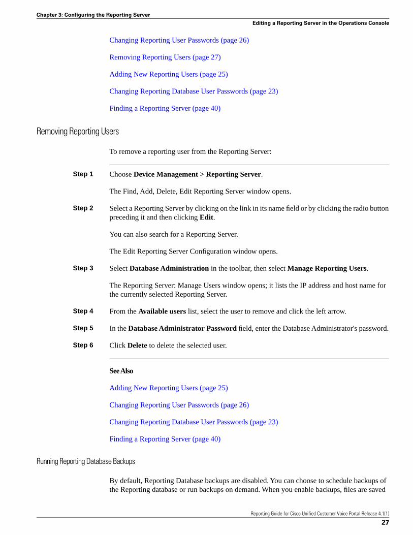
Removing Reporting Users
To remove a reporting user from the Reporting Server:
Step 1 Choose Device Management > Reporting Server.
The Find, Add, Delete, Edit Reporting Server window opens.
Step 2 Select a Reporting Server by clicking on the link in its name field or by clicking the radio buttonpreceding it and then clicking Edit.
You can also search for a Reporting Server.
The Edit Reporting Server Configuration window opens.
Step 3 Select Database Administration in the toolbar, then select Manage Reporting Users.
The Reporting Server: Manage Users window opens; it lists the IP address and host name forthe currently selected Reporting Server.
Step 4 From the Available users list, select the user to remove and click the left arrow.
Step 5 In the Database Administrator Password field, enter the Database Administrator's password.
Step 6 Click Delete to delete the selected user.
See Also
Adding New Reporting Users (page 25)
Changing Reporting User Passwords (page 26)
Changing Reporting Database User Passwords (page 23)
Finding a Reporting Server (page 40)
Running Reporting Database Backups
By default, Reporting Database backups are disabled. You can choose to schedule backups ofthe Reporting database or run backups on demand. When you enable backups, files are saved
Reporting Guide for Cisco Unified Customer Voice Portal Release 4.1(1)
27
Chapter 3: Configuring the Reporting Server
Editing a Reporting Server in the Operations Console

to the Reporting Server's local file system. You are responsible for managing backed-up files.Scheduled backups occur once each day. You can configure the time of day at which backupsoccur. A maximum of two backups and a minimum of one backup will be available at any timeon the local machine.
Procedure
To run a reporting database backup:
Step 1 Choose Device Management > CVP Reporting Server.
The Find, Add, Delete, Edit Reporting Servers window opens.
Step 2 Click Edit.
The Reporting Server Configuration window opens with the current settings displayed.
Step 3 Select the Database Administration menu in the toolbar, then select Reporting DatabaseBackups.
The Reporting Server - Database Backup Activities page appears; it lists the IP address and hostname for the currently selected Reporting Server.
Step 4 To launch a backup immediately, click Backup Now. To schedule a time for daily backups,select Schedule Daily Backups and then select the hour and minute of the start time.
Step 5 Enter the Database Administrator Password and click Save & Deploy.
See Also
Changing a Reporting Database User Password (page 23)
Configuring Reporting Database Purge (page 29)
Managing Reporting Users (page 25)
Viewing Reporting Database Details (page 31)
Getting Reporting Server Statistics (page 39)
Cancelling Reporting Database Backups
By default, Reporting Database backups are disabled. You can choose to schedule backups ofthe Reporting database or run backups on demand. You can cancel daily backups at any time.
Procedure
To cancel a reporting database backup:
Reporting Guide for Cisco Unified Customer Voice Portal Release 4.1(1)
28
Chapter 3: - Configuring the Reporting Server
Editing a Reporting Server in the Operations Console

Step 1 Choose Device Management > CVP Reporting Server.
The Find, Add, Delete, Edit Reporting Servers window opens.
Step 2 Select a Reporting Server by clicking on the link in its name field or by clicking the radio buttonpreceding it and then clicking Edit.
The Edit Reporting Server Configuration window opens with the current settings displayed.
Step 3 Select the Database Administration menu in the toolbar, then select Reporting DatabaseBackups.
The Reporting Server - Database Backup Activities page displays. The IP address and hostname for the currently selected Reporting Server are listed.
Step 4 Click Cancel Daily Backups.
Step 5 Enter your Database Administrator Password and click Save & Deploy.
See Also
Changing a Reporting Database User Password (page 23)
Configuring Reporting Database Purge (page 29)
Managing Reporting Users (page 25)
Viewing Reporting Database Details (page 31)
Getting Reporting Server Statistics (page 39)
Configuring Reporting Database Purge
You can purge call data from the Reporting Database. Data purge is run daily at the time youspecify. Each category of call data is retained for a default number of days, before being purged.
Procedure
To configure Reporting Database purge settings:
Step 1 Choose Device Management > CVP Reporting Server.
The Find, Add, Delete, Edit Reporting Servers window opens.
Step 2 Select a Reporting Server by clicking on the link in its name field or by clicking the radio buttonpreceding it and then clicking Edit.
The Edit Reporting Server Configuration window opens with the current settings displayed.
Reporting Guide for Cisco Unified Customer Voice Portal Release 4.1(1)
29
Chapter 3: Configuring the Reporting Server
Editing a Reporting Server in the Operations Console
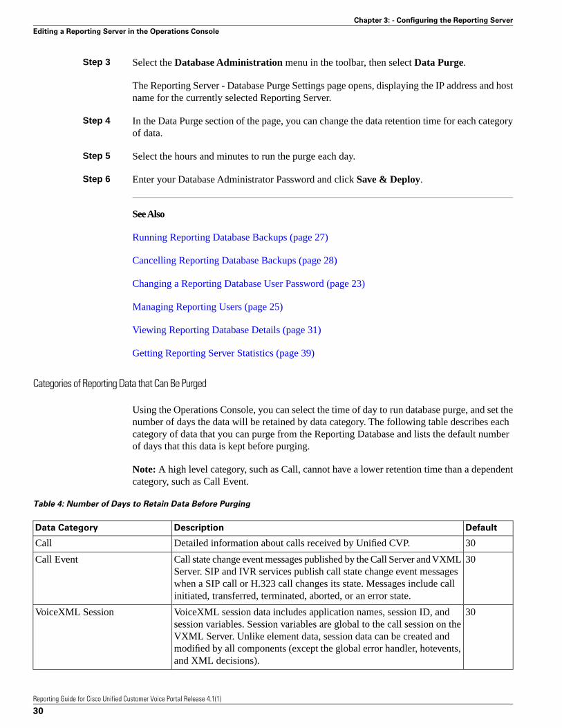
Step 3 Select the Database Administration menu in the toolbar, then select Data Purge.
The Reporting Server - Database Purge Settings page opens, displaying the IP address and hostname for the currently selected Reporting Server.
Step 4 In the Data Purge section of the page, you can change the data retention time for each categoryof data.
Step 5 Select the hours and minutes to run the purge each day.
Step 6 Enter your Database Administrator Password and click Save & Deploy.
See Also
Running Reporting Database Backups (page 27)
Cancelling Reporting Database Backups (page 28)
Changing a Reporting Database User Password (page 23)
Managing Reporting Users (page 25)
Viewing Reporting Database Details (page 31)
Getting Reporting Server Statistics (page 39)
Categories of Reporting Data that Can Be Purged
Using the Operations Console, you can select the time of day to run database purge, and set thenumber of days the data will be retained by data category. The following table describes eachcategory of data that you can purge from the Reporting Database and lists the default numberof days that this data is kept before purging.
Note: A high level category, such as Call, cannot have a lower retention time than a dependentcategory, such as Call Event.
Table 4: Number of Days to Retain Data Before Purging
DefaultDescriptionData Category
30Detailed information about calls received by Unified CVP.Call
30Call state change event messages published by the Call Server and VXMLServer. SIP and IVR services publish call state change event messages
Call Event
when a SIP call or H.323 call changes its state. Messages include callinitiated, transferred, terminated, aborted, or an error state.
30VoiceXML session data includes application names, session ID, andsession variables. Session variables are global to the call session on the
VoiceXML Session
VXML Server. Unlike element data, session data can be created andmodified by all components (except the global error handler, hotevents,and XML decisions).
Reporting Guide for Cisco Unified Customer Voice Portal Release 4.1(1)
30
Chapter 3: - Configuring the Reporting Server
Editing a Reporting Server in the Operations Console

DefaultDescriptionData Category
15A VoiceXML element is a distinct component of a voice application callflow whose actions affect the experience of the caller. A VoiceXML
VoiceXML Element
element contains detailed script activity to the element level, such as,Call Identifiers, activity time stamp, VoiceXML script name, name andtype of the VoiceXML element, and event type.
15Expanded Call Context (ECC) variables that are included in VoiceXMLdata. Unified CVP uses ECC variables to exchange information with
VoiceXML ECC Variable
Unified ICME. For a complete list and description of ECC variables,see the Configuration and Administration Guide for Cisco UnifiedCustomer Voice Portal .
15Application detailed data at the script element level from the VXMLServer call services. This data includes input mode, utterance,interpretation, and confidence.
VoiceXML Voice Interact Detail
15VoiceXML session variables are global to the call session on the VXMLServer.
VoiceXML Session Variable
15The names and values of element variables.VoiceXML Element Detail
The data categories are hierarchical as described in Data Categories (page 12).
Viewing Database Details
You can view the size of a Reporting database.
Procedure
To view database details:
Step 1 Choose Device Management > CVP Reporting Server.
The Find, Add, Delete, Edit Reporting Servers window opens.
Step 2 Select a Reporting Server by clicking on the link in its name field or by clicking the radio buttonpreceding it and then clicking Edit.
The Edit Reporting Server Configuration window opens with the current settings displayed.
Step 3 Select the Database Administration menu in the toolbar, then select Database Details.
The Reporting Server - Disk Drives: Housing Database Files page opens, displaying the IPaddress and host name for the currently selected Reporting Server along with the followingdatabase information:
Reporting Guide for Cisco Unified Customer Voice Portal Release 4.1(1)
31
Chapter 3: Configuring the Reporting Server
Editing a Reporting Server in the Operations Console

Reporting Database Details:
• Database Name - Name of the database
• Total Size (MB) - Total data size
• Free size (MB) - Amount of space that has not been taken by extents
• Used Size (MB) - Data space used
• Extent size (MB) - Space reserved for tables. This size may be greater than the total size.
• % Free Size - The percent of space that has not been extended (reserved). This might begreater than 100%.
See Also
Running Reporting Database Backups (page 27)
Cancelling Reporting Database Backups (page 28)
Changing a Reporting Database User Password (page 23)
Configuring Reporting Database Purge (page 29)
Managing Reporting Users (page 25)
Getting Reporting Server Statistics (page 39)
Guidelines for Choosing Secure Passwords
Note: Reporting passwords are subject to both the Unified CVP password policy, which isindicated below, and the password policy enforced by the operating system of the computer onwhich the Reporting Server resides. For each aspect of the password, the Reporting passwordmust meet the requirement of the more restrictive policy.
Passwords must meet all the following criteria:
Passwords must only contain the following ASCII characters:
• Maximum password length is eighty (80) characters.
• Minimum password length is eight (8) characters.
• The password must contain characters from at least three of the following classes: lowercaseletters, uppercase letters, digits, and special characters.
– Lowercase letters (abcdefghijklmnopqrstuvwxyz)
– Uppercase letters (ABCDEFGHIJKLMNOPQRSTUVWXYZ)
Reporting Guide for Cisco Unified Customer Voice Portal Release 4.1(1)
32
Chapter 3: - Configuring the Reporting Server
Editing a Reporting Server in the Operations Console

– Digits (0123456789)
– The following special characters:
!"#$%&'()*+,-./
:;<=>?@
[\]^_`
{|}~
• No character in the password can be repeated more than three (3) times consecutively.
• Password must not repeat or reverse username. Password is not "cisco", "ocsic", or any variantobtained by changing the capitalization of letters therein.
Uploading a Log Messages XML File
You can download a Log Messages XML file, CVPLogMessages.xml, to your local machinefrom any Unified CVP server. After downloading the file, you can edit it to configure the wayUnified CVP event notifications are handled. Then after you edit the file, you can upload thecustomized file to any Unified CVP server.
If you want to transfer multiple files at a time, use the Bulk Administration menu.
Procedure
To upload a Log Messages XML file from a Unified CVP Server to the Operations Console:
Step 1 From the Device Management menu, choose the type of server to which you want to uploada syslog XML file. For example, to upload a file to a VXML Server, choose Device Management> VXML Server.
The Find, Add, Delete, Edit window lists servers that have been added to the control panel.
Step 2 Select a server by clicking on the link in its Hostname field or by clicking the radio buttonpreceding it and then clicking Edit.
Step 3 Select File Transfer in the toolbar and then click Log Messages XML File Upload.
The Log Messages XML Upload page displays.
Step 4 In the Select a Log Messages XML file from your local PC text box, enter a file name or clickBrowse and search for the file on your local system..
Step 5 Click Upload to transfer the selected file to the Unified CVP Server.
Step 6 Shut down and then start the corresponding Unified CVP Server.
Reporting Guide for Cisco Unified Customer Voice Portal Release 4.1(1)
33
Chapter 3: Configuring the Reporting Server
Editing a Reporting Server in the Operations Console

See Also
Downloading a Log Messages XML File (page 33)
Editing the Log Messsages XML File (page 35)
Bulk Administration File Transfer (page 50)
Downloading a Log Messages XML File
You can download a Log Messages XML file, CVPLogMessages.xml, to your local machinefrom any Unified CVP server. After downloading the file, you can edit it to configure the wayUnified CVP event notifications are handled. Then after you edit the file, you can upload thecustomized file to any Unified CVP server.
If you want to transfer multiple files at a time, use the Bulk Administration menu.
Procedure
To download a Log Messages XML file from the Operations Console to a Unified CVP Server:
Step 1 From the Device Management menu, choose the type of server from which you want to downloada syslog XML file. For example, to download a file to a VXML Server, choose DeviceManagement > VXML Server.
The Find, Add, Delete, Edit window lists any servers that have been added to the control panel.
Step 2 Select a server by clicking on the link in its Hostname field or by clicking the radio buttonpreceding it and then clicking Edit.
Step 3 Select File Transfer in the toolbar and then click Log Messages XML File Download.
The Log Messages XML Download page displays.
Step 4 Click Download to transfer the XML file to the server.
A message indicates that this operation might take some time. Click OK to continue with thedownload or click Cancel to cancel the download.
See Also
Uploading a Log Messages XML File (page 33)
Editing the Log Messages XML File (page 35)
Bulk Administration File Transfer (page 50)
Reporting Guide for Cisco Unified Customer Voice Portal Release 4.1(1)
34
Chapter 3: - Configuring the Reporting Server
Editing a Reporting Server in the Operations Console

Editing the Log Messages XML File
The log messages XML file, CVPLogMessages.xml, defines the severity, destination (SNMPmanagement station or Syslog server) and possible resolution for Unified CVP log messages.This file also identifies an event type identifier and message text identifier for each event. Theidentifiers are stored in the resource properties file, CVPLogMessages.properties.
Each Unified CVP Call Server, VXML Server, and Reporting Server has a log messages XMLfile and log message file. You can edit the CVPLogMessages.xml file on a particular UnifiedCVP server to customize the severity, destination and possible resolution for each event thatthe server generates. You can also edit the CVPLogMessages.properties file to change thetext of the message that is generated when an event occurs on that server.
Use any plain-text editor (one that does not create any markup) or XML editor to edit theCVPLogMessages.xml file. Use a resource file editor, if available, to edit theCVPLogMessages.properties file. If a resource file editor is not available, use a text editor.
What it MeansPossible ValuesMessage Element
Identifies the event type described in theCVPLogMessages.properties file.
Resource="identifier"Name
Identifies the message text described in theCVPLogMessages.properties file.
Resource="identifier"Body
Identifies the severity level (page 35) of the event.0 to 6Severity
Set to true, to send this message, when logged, to anSNMP manager, if one is configured.
True or falseSendToSNMP
Set to true to send this message, when logged, to aSyslog server, if one is configured.
True or falseSendToSyslog
Set to true to identify this message, when logged, asan SNMP raise event, which the SNMP management
True or falseSNMPRaise
station can use to initiate a task or automatically takean action.
Set to false to identify this message as an SNMP clearwhen sent to an SNMP management station. AnSNMP clear event usually corresponds to an SNMPraise event, indicating that the problem causing theraise has been corrected. An administrator on anSNMP management station can correlate SNMP raiseevents with SNMP clear events.
Unified CVP Event Severity Levels
The following table describes the available severity levels for Unified CVP events. You can setthe severity level for an event by editing the log messages XML file, CVPLogMessages.xml,on the server that generates events. For instructions on editing this file, see Editing the LogMessages XML File (page 35).
Reporting Guide for Cisco Unified Customer Voice Portal Release 4.1(1)
35
Chapter 3: Configuring the Reporting Server
Editing a Reporting Server in the Operations Console

PurposeSeverityLevel
System or service is unusable0EMERGENCY
Action must be taken immediately1ALERT
Critical condition, similar to ALERT, but not necessarilyrequiring an immediate action
2CRITICAL
An error condition that does not necessarily impact theability of the service to continue to function
3ERROR
A warning about a bad condition, which is not necessarilyan error
4WARN
Notification about interesting system-level conditions,which are not errors
5NOTICE
Information about internal flows or application orper-request information, not system-wide information
6INFO
Applying a License to a Reporting Server Using the Operations Console
Applying a License to a Reporting Server
You must apply a valid license file after configuring a Reporting Server. You can browse forand upload the license file to the Operations Console, and then transfer the license to theReporting Server. Select either an existing license file in the Operations Console database or anew license file from your local desktop.
Note: Each Reporting Server IP address requires a unique license. You must apply the correctlicense to the Reporting Server.
Procedure
To apply a license file:
Step 1 Choose Device Management > CVP Reporting Server.
The Find, Add, Delete, Edit Reporting Server window lists any Reporting Servers that havebeen added to the control panel.
Step 2 Select a Reporting Server by clicking on the link in its name field or by clicking the radio buttonpreceding it and then clicking Edit.
You can also search for a Reporting Server.
The Edit Reporting Server Configuration window opens.
Step 3 Select File Transfer in the toolbar and then click Licensing.
The File Transfer page displays.
Reporting Guide for Cisco Unified Customer Voice Portal Release 4.1(1)
36
Chapter 3: - Configuring the Reporting Server
Applying a License to a Reporting Server Using the Operations Console
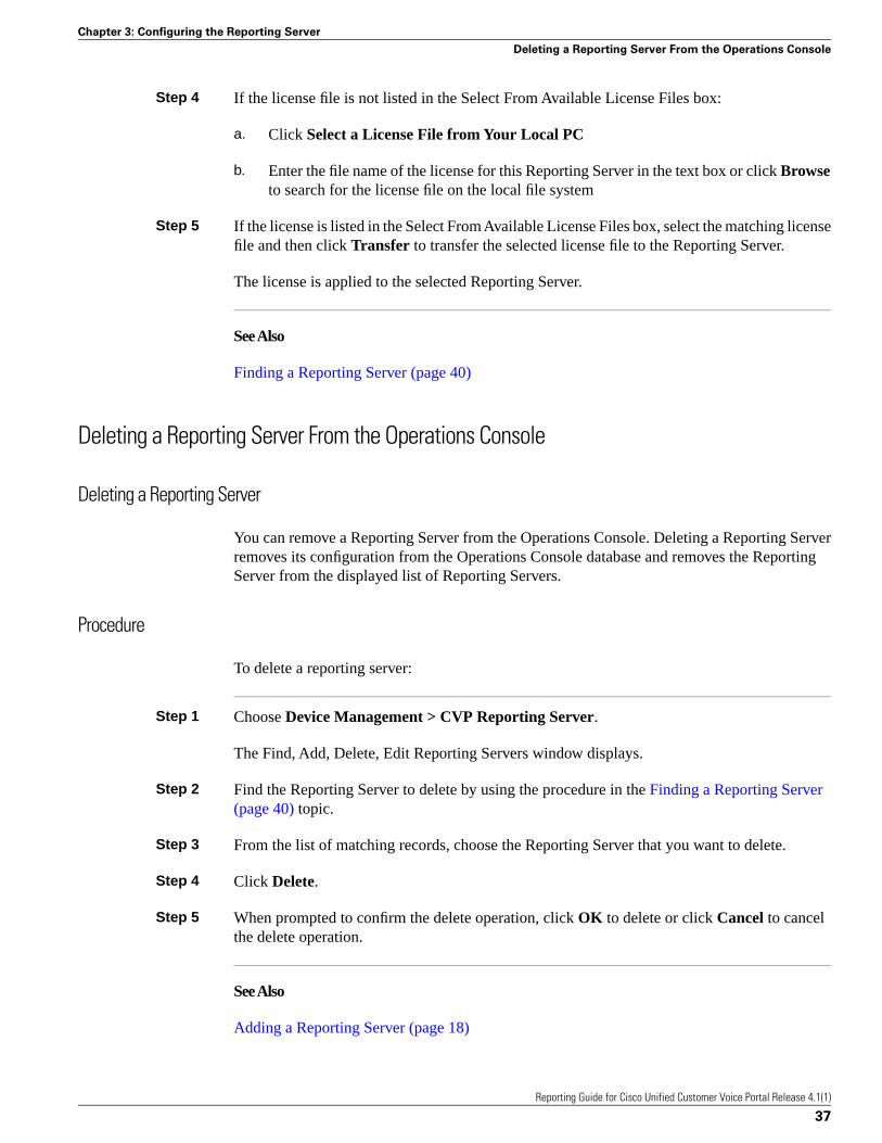
Step 4 If the license file is not listed in the Select From Available License Files box:
a. Click Select a License File from Your Local PC
b. Enter the file name of the license for this Reporting Server in the text box or click Browseto search for the license file on the local file system
Step 5 If the license is listed in the Select From Available License Files box, select the matching licensefile and then click Transfer to transfer the selected license file to the Reporting Server.
The license is applied to the selected Reporting Server.
See Also
Finding a Reporting Server (page 40)
Deleting a Reporting Server From the Operations Console
Deleting a Reporting Server
You can remove a Reporting Server from the Operations Console. Deleting a Reporting Serverremoves its configuration from the Operations Console database and removes the ReportingServer from the displayed list of Reporting Servers.
Procedure
To delete a reporting server:
Step 1 Choose Device Management > CVP Reporting Server.
The Find, Add, Delete, Edit Reporting Servers window displays.
Step 2 Find the Reporting Server to delete by using the procedure in the Finding a Reporting Server(page 40) topic.
Step 3 From the list of matching records, choose the Reporting Server that you want to delete.
Step 4 Click Delete.
Step 5 When prompted to confirm the delete operation, click OK to delete or click Cancel to cancelthe delete operation.
See Also
Adding a Reporting Server (page 18)
Reporting Guide for Cisco Unified Customer Voice Portal Release 4.1(1)
37
Chapter 3: Configuring the Reporting Server
Deleting a Reporting Server From the Operations Console
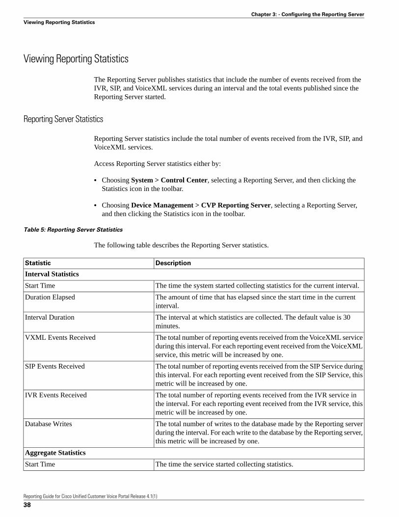
Viewing Reporting Statistics
The Reporting Server publishes statistics that include the number of events received from theIVR, SIP, and VoiceXML services during an interval and the total events published since theReporting Server started.
Reporting Server Statistics
Reporting Server statistics include the total number of events received from the IVR, SIP, andVoiceXML services.
Access Reporting Server statistics either by:
• Choosing System > Control Center, selecting a Reporting Server, and then clicking theStatistics icon in the toolbar.
• Choosing Device Management > CVP Reporting Server, selecting a Reporting Server,and then clicking the Statistics icon in the toolbar.
Table 5: Reporting Server Statistics
The following table describes the Reporting Server statistics.
DescriptionStatistic
Interval Statistics
The time the system started collecting statistics for the current interval.Start Time
The amount of time that has elapsed since the start time in the currentinterval.
Duration Elapsed
The interval at which statistics are collected. The default value is 30minutes.
Interval Duration
The total number of reporting events received from the VoiceXML serviceduring this interval. For each reporting event received from the VoiceXMLservice, this metric will be increased by one.
VXML Events Received
The total number of reporting events received from the SIP Service duringthis interval. For each reporting event received from the SIP Service, thismetric will be increased by one.
SIP Events Received
The total number of reporting events received from the IVR service inthe interval. For each reporting event received from the IVR service, thismetric will be increased by one.
IVR Events Received
The total number of writes to the database made by the Reporting serverduring the interval. For each write to the database by the Reporting server,this metric will be increased by one.
Database Writes
Aggregate Statistics
The time the service started collecting statistics.Start Time
Reporting Guide for Cisco Unified Customer Voice Portal Release 4.1(1)
38
Chapter 3: - Configuring the Reporting Server
Viewing Reporting Statistics

DescriptionStatistic
The amount of time that has elapsed since the service start time.Duration Elapsed
The total number of reporting events received from the VoiceXML Servicesince the service started. For each reporting event received from theVoiceXML Service, this metric will be increased by one.
VXML Events Received
The total number of reporting events received from the SIP Service sincethe service started. For each reporting event received from the SIP Service,this metric will be increased by one.
SIP Events Received
The total number of reporting events received from the IVR Service sincethe service started. For each reporting event received from the IVR Service,this metric will be increased by one.
IVR Events Received
The total number of writes to the database made by the Reporting serversince startup. For each write to the database by the Reporting server, thismetric will be increased by one.
Database Writes
Getting Reporting Statistics
Reporting Server statistics include the total number of events received from the IVR, SIP, andVoiceXML services.
Procedure
To get Reporting Server statistics:
Step 1 Choose Device Management > CVP Reporting Server.
The Find, Add, Delete, Edit Reporting Servers window opens.
Step 2 Select a Reporting Server by clicking on the link in its name field or by clicking the radio buttonpreceding it and then clicking Edit.
The Edit Reporting Server Configuration window opens with the current settings displayed.
Step 3 Select Statistics in the toolbar.
The Reporting Server statistics (page 38) are listed in the Reporting tab.
See Also
Running Reporting Database Backups (page 27)
Cancelling Reporting Database Backups (page 28)
Changing a Reporting Database User Password (page 23)
Configuring Reporting Database Purge (page 29)
Reporting Guide for Cisco Unified Customer Voice Portal Release 4.1(1)
39
Chapter 3: Configuring the Reporting Server
Viewing Reporting Statistics
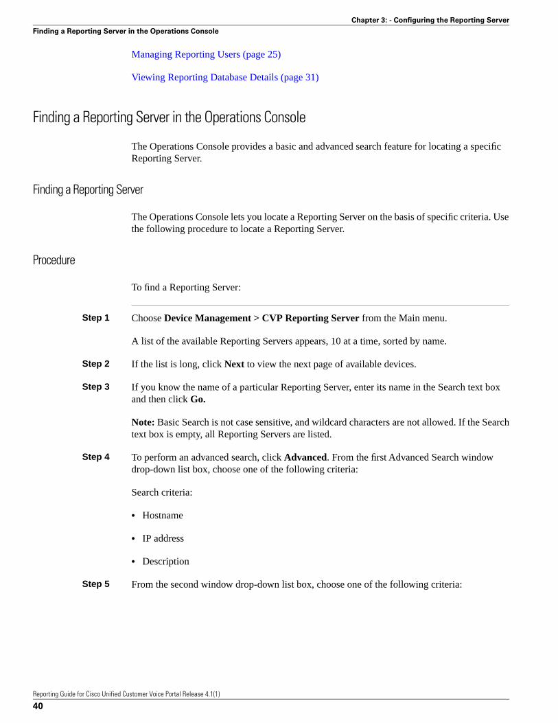
Managing Reporting Users (page 25)
Viewing Reporting Database Details (page 31)
Finding a Reporting Server in the Operations Console
The Operations Console provides a basic and advanced search feature for locating a specificReporting Server.
Finding a Reporting Server
The Operations Console lets you locate a Reporting Server on the basis of specific criteria. Usethe following procedure to locate a Reporting Server.
Procedure
To find a Reporting Server:
Step 1 Choose Device Management > CVP Reporting Server from the Main menu.
A list of the available Reporting Servers appears, 10 at a time, sorted by name.
Step 2 If the list is long, click Next to view the next page of available devices.
Step 3 If you know the name of a particular Reporting Server, enter its name in the Search text boxand then click Go.
Note: Basic Search is not case sensitive, and wildcard characters are not allowed. If the Searchtext box is empty, all Reporting Servers are listed.
Step 4 To perform an advanced search, click Advanced. From the first Advanced Search windowdrop-down list box, choose one of the following criteria:
Search criteria:
• Hostname
• IP address
• Description
Step 5 From the second window drop-down list box, choose one of the following criteria:
Reporting Guide for Cisco Unified Customer Voice Portal Release 4.1(1)
40
Chapter 3: - Configuring the Reporting Server
Finding a Reporting Server in the Operations Console

Search criteria:
• begins with
• contains
• ends with
• is exactly
• is empty
Step 6 Specify the appropriate search text, if applicable, and click Find.
Adding and Removing a Device from a Device Pool
Device Pools are logical groupings of devices, for example, SanJose-Gateways. Device poolsprovide a convenient way to define a set of common characteristics that can be assigned todevices, for example, the region in which the devices are located. The system creates a defaultdevice pool, which contains all devices. Every device you create is automatically assigned tothe default device pool. You can never remove the default device pool from the selected devicepool list. The default device pool ensures that the Administrator can view and manage all devices.You can create device pools and assign devices to the device pools you created.
Adding or Removing a Device From a Device Pool
Procedure
To add or remove a device from a device pool:
Step 1 From the Device Management menu, choose the type of device you want to add to or removefrom a device pool. For example, to add a Reporting Server to a device pool, select CVPReporting Server from the menu.
A window listing known devices of the type you selected displays. For example, if you selectedReporting Server, known CVP Reporting Servers are listed.
Step 2 Select the device by checking the checkbox preceding it or highlighting the device and thenclicking Edit.
Step 3 Select the Device Pool tab.
Step 4 Then:If:
Select the device pool from the Available pane, and thenclick the right arrow to move the pool to the Selected pane.
You want to add a device to adevice pool
Reporting Guide for Cisco Unified Customer Voice Portal Release 4.1(1)
41
Chapter 3: Configuring the Reporting Server
Adding and Removing a Device from a Device Pool
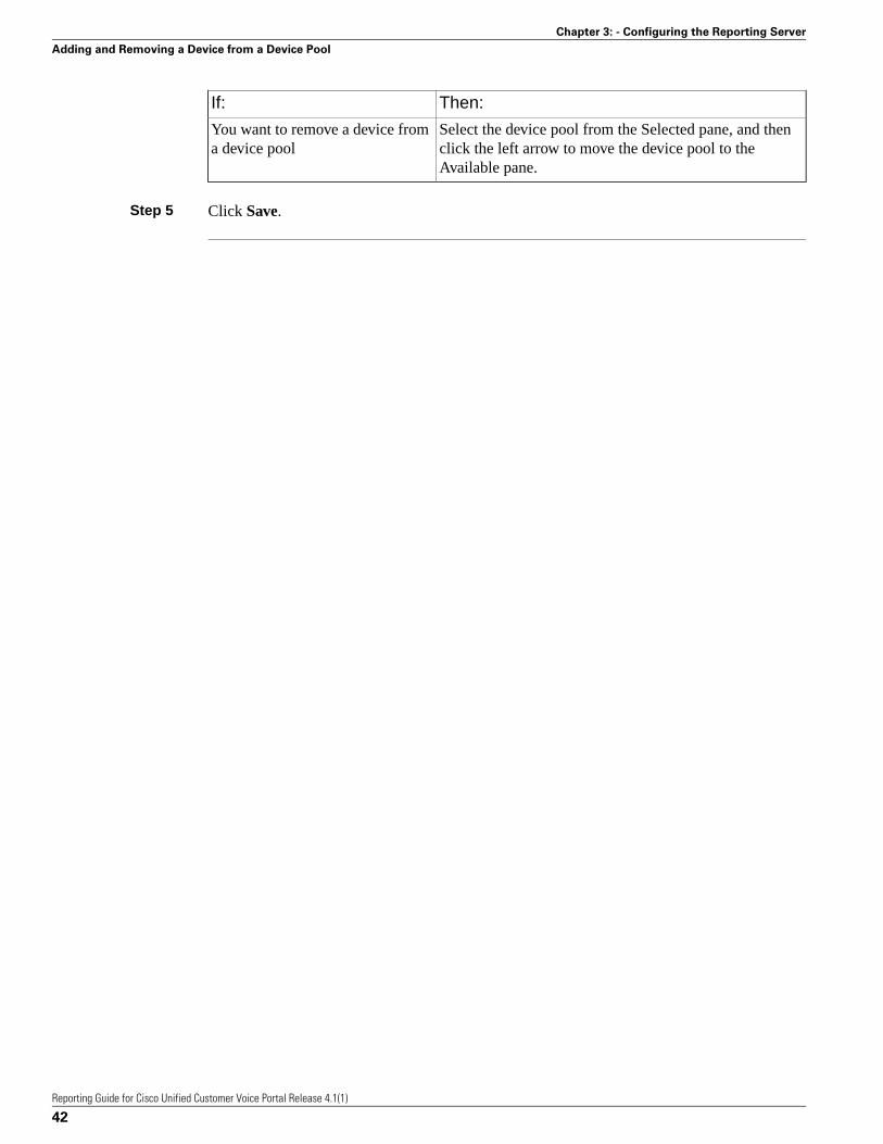
Then:If:
Select the device pool from the Selected pane, and thenclick the left arrow to move the device pool to theAvailable pane.
You want to remove a device froma device pool
Step 5 Click Save.
Reporting Guide for Cisco Unified Customer Voice Portal Release 4.1(1)
42
Chapter 3: - Configuring the Reporting Server
Adding and Removing a Device from a Device Pool

Configuring the VXML Server for ReportingThe VXML Server is a J2EE-compliant application server that provides a complete solutionfor rapidly creating and deploying dynamic VoiceXML applications. If you installed a VXMLServer, you must configure it before using it to deploy VoiceXML applications or licenses.
This section contains the following topics:
• Adding a VXML Server to the Operations Console, page 43• Editing a VXML Server in the Operations Console, page 45• Transferring a File to Multiple Devices, page 50
Adding a VXML Server to the Operations Console
Adding a VXML Server to the Operations Console adds its configuration to the OperationsConsole database and adds it to the list of VXML Servers in the Control Panel. When you adda VXML Server, you must associate it with a Call Server. The VXML Server uses the messageservice on this Call Server to communicate with the Reporting Server.
You can also add a VXMLServer to one or more logical groups of devices, called device pools,and configure publishing statistics. See Adding and Removing a Device from a Device Pool(page 41) for additional information about how to add a server to a device pool.
Adding a VXML Server
Before You Begin
Reporting Guide for Cisco Unified Customer Voice Portal Release 4.1(1)
43
Chapter 4

Do the following before adding a VXML Server to the Operations Console:
• Collect the host name or IP address of the VXML Server during the installation of UnifiedCVP software.
• Install and configure at least one Call Server before configuring the VXML Server.
• Review Call Studio scripts, noting any of the following items you want to include or excludefrom VXML Server reporting data:
– Application names
– Element types
– Element names
– Element fields
– ECC variables
Procedure
To add a VXML Server:
Step 1 Choose Device Management > VXML Server.
The Find, Add, Delete, Edit VXML Servers window opens.
Note: To use an existing VXML Server as a template for creating the new VXML Server, selectthe VXML Server by clicking the radio button preceding it and then click Use As Template.
Step 2 Click Add New.
The VXML Server Configuration window opens to the General Tab.
Step 3 Enter the general server information and choose a primary Call Server.
Step 4 Optionally, choose a backup Call Server.
Step 5 Select the Configuration Tab, then configure VXML Server properties.
Step 6 Optionally, select the Device Pool tab and add the VXML Server to a device pool.
Step 7 Optionally, select the Infrastructure tab and configure log file and syslog settings.
Step 8 When you finish configuring the VXML Server:
a. click Save to save the settings in the Operations Server database
b. OR click Save & Deploy to save the settings in the Operations Server database and deploythe changes to the Reporting Server
Reporting Guide for Cisco Unified Customer Voice Portal Release 4.1(1)
44
Chapter 4: - Configuring the VXML Server for Reporting
Adding a VXML Server to the Operations Console

Step 9 Shut down and then restart the VXML Server and the primary and backup Call Servers.
Editing a VXML Server in the Operations Console
You can change the properties of a VXML Server that has been added to the Operations Console.In edit mode, the Statistics, File Transfer, and System Id menus are also available. From theStatistics menu, you can view call statistics published by the VXML Server. From the FileTransfer menu, you can transfer license files, VoiceXML script files, and log messages to theVXML Server. The System Id menu provides an option to generate a unique system identifierfor the XML Server. You will need the System Id when getting a license for this server.
Editing a VXML Server
Before You Begin
You can edit the configuration for a VXML Server that has been added to the Operations ConsoleControl Center.
Procedure
To edit a VXML Server configuration:
Step 1 Choose Device Management > VXML Server.
The Find, Add, Delete, Edit VXML Servers window opens.
Step 2 From the list of matching records, choose the VXML Server that you want to edit.
Step 3 Click Edit.
The VXML Server Configuration window opens to the General Tab.
Step 4 Change any general server information. You cannot change the IP address of the VXML Server.
Step 5 Select the Configuration Tab, then configure VXML Server properties.
Step 6 Optionally, select the Device Pool tab and add the VXML Server to a device pool.
Step 7 Optionally, select the Infrastructure tab and configure log file and syslog settings.
Step 8 When you finish configuring the VXML Server:
a. click Save to save the settings in the Operations Server database
b. OR click Save & Deploy to save the settings in the Operations Server database and deploythe changes to the Reporting Server
Reporting Guide for Cisco Unified Customer Voice Portal Release 4.1(1)
45
Chapter 4: Configuring the VXML Server for Reporting
Editing a VXML Server in the Operations Console

Step 9 Shut down and then restart the VXML Server and—if they have changed—the primary andbackup Call Servers.
VXML Server General Properties
You can configure settings that identify the VXML Server and choose a primary, and optionally,a backup Call Server to communicate with the Reporting Server. You can also enable securecommunications between the Operations Console and the VXML Server.
Table 6: VXML Server General Configuration Settings
Restart/Reboot
Needed
RangeDefaultDescriptionField
General
NoA valid IP addressNoneThe IP address of the VXML ServerIP Address
NoA valid DNS name,which includes uppercase
NoneThe host name of the VXML Server.Host names must be valid DNS names,
Hostname
and lowercase letters inwhich can include letters in the alphabet,the numbers 0 through 9, and a dash. the alphabet, the numbers
0 through 9, and a dash
NoLess than or equal to1024 characters
NoneThe description of the VXML Server.Description
Yes - rebootOn or OffNoneSelect to enable secure communicationsbetween the Operations Console and this
Enable securecommunication
component. The device is accessed usingwith the OperationsConsole SSH and files are transferred using
HTTPS.
Call Servers
Yes - Restart CallServer andVXML Server
Not applicableNoneThe VXML Server uses the messageservice on this Call Server tocommunicate with the Reporting Server.
Primary Call Server
Select a primary Call Server from thedrop-down list. The drop-down listincludes all Call Servers added to theOperations Console.
Yes - Restart CallServer andVXML Server
Not applicableNoneThe VXML Server uses the messageservice on this Call Server tocommunicate with the Reporting Server
Backup Call Server
if the Primary Call Server isunreachable. Select a backup Call Serverfrom the drop-down list. The drop-downlist includes all Call Servers added to theOperations Console.
Reporting Guide for Cisco Unified Customer Voice Portal Release 4.1(1)
46
Chapter 4: - Configuring the VXML Server for Reporting
Editing a VXML Server in the Operations Console
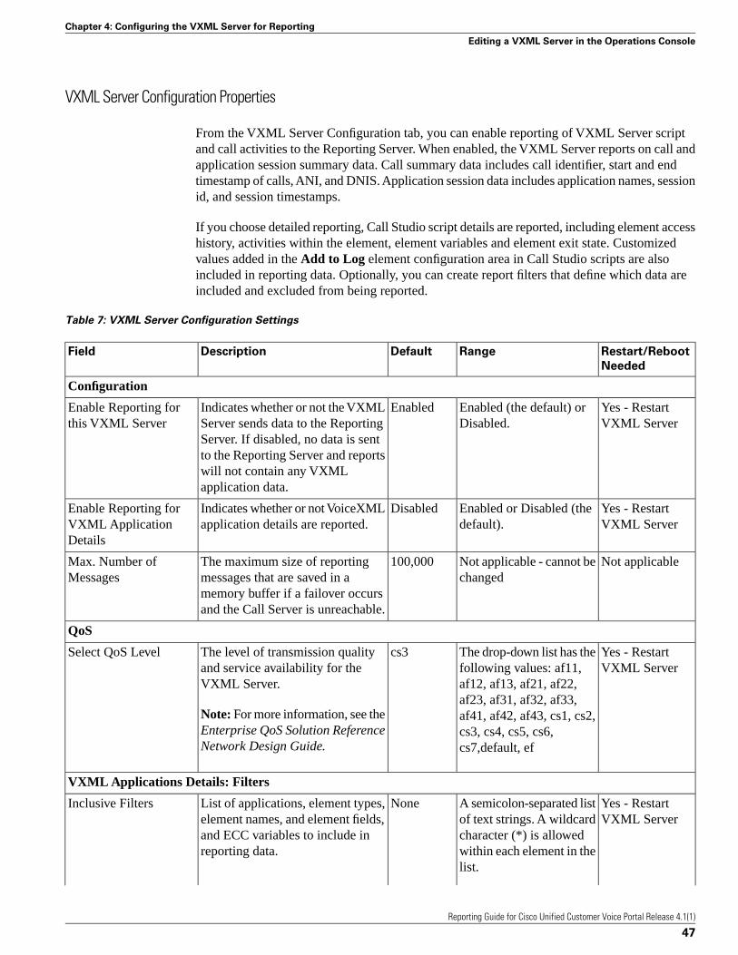
VXML Server Configuration Properties
From the VXML Server Configuration tab, you can enable reporting of VXML Server scriptand call activities to the Reporting Server. When enabled, the VXML Server reports on call andapplication session summary data. Call summary data includes call identifier, start and endtimestamp of calls, ANI, and DNIS. Application session data includes application names, sessionid, and session timestamps.
If you choose detailed reporting, Call Studio script details are reported, including element accesshistory, activities within the element, element variables and element exit state. Customizedvalues added in the Add to Log element configuration area in Call Studio scripts are alsoincluded in reporting data. Optionally, you can create report filters that define which data areincluded and excluded from being reported.
Table 7: VXML Server Configuration Settings
Restart/Reboot
Needed
RangeDefaultDescriptionField
Configuration
Yes - RestartVXML Server
Enabled (the default) orDisabled.
EnabledIndicates whether or not the VXMLServer sends data to the Reporting
Enable Reporting forthis VXML Server
Server. If disabled, no data is sentto the Reporting Server and reportswill not contain any VXMLapplication data.
Yes - RestartVXML Server
Enabled or Disabled (thedefault).
DisabledIndicates whether or not VoiceXMLapplication details are reported.
Enable Reporting forVXML ApplicationDetails
Not applicableNot applicable - cannot bechanged
100,000The maximum size of reportingmessages that are saved in a
Max. Number ofMessages
memory buffer if a failover occursand the Call Server is unreachable.
QoS
Yes - RestartVXML Server
The drop-down list has thefollowing values: af11,
cs3The level of transmission qualityand service availability for theVXML Server.
Select QoS Level
af12, af13, af21, af22,af23, af31, af32, af33,
Note: For more information, see theEnterprise QoS Solution ReferenceNetwork Design Guide.
af41, af42, af43, cs1, cs2,cs3, cs4, cs5, cs6,cs7,default, ef
VXML Applications Details: Filters
Yes - RestartVXML Server
A semicolon-separated listof text strings. A wildcard
NoneList of applications, element types,element names, and element fields,
Inclusive Filters
character (*) is allowedand ECC variables to include inreporting data. within each element in the
list.
Reporting Guide for Cisco Unified Customer Voice Portal Release 4.1(1)
47
Chapter 4: Configuring the VXML Server for Reporting
Editing a VXML Server in the Operations Console

Restart/Reboot
Needed
RangeDefaultDescriptionField
Note: For moreinformation about filtersyntax and rules, seeInclusive and ExclusiveVoiceXML Filters forReporting (page 48).
Yes - RestartVXML Server
A semicolon-separated listof text strings. A wildcard
NoneList of applications, element types,element names, and element fields,
Exclusive Filters
character (*) is allowedand ECC variables to exclude fromreporting data. within each element in the
list.
Note: For moreinformation about filtersyntax and rules, seeInclusive and ExclusiveVoiceXML Filters forReporting (page 48).
Inclusive and Exclusive VoiceXML Filters for Reporting
You use Inclusive and Exclusive VoiceXML filters to control the data that the VXML Serverfeeds to the Reporting Server. Data feed control is crucial for:
• Saving space on the reporting database.
• Preserving messaging communication bandwidth.
Rules for VoiceXML Inclusive and Exclusive Filters
Inclusive and exclusive filters operate using the following rules:
• By default, all items but the Start, Subdialog_Start, and Subdialog_End elements are filteredfrom reporting data unless they are added to an Inclusive Filter. The Subdialog_Start andSubdialog_End elements are never filtered from reporting data unless Reporting is disabledon the VXML Server.
• The Exclusive Filter takes precedence over the Inclusive Filter. For example, if an applicationname is in the Exclusive Filter, then all of the items of that applications are excluded fromreporting data even if a particular field or element is listed in the Inclusive filter.
• The syntax for Inclusive/Exclusive filters is:
Appname.ElementType.ElementName.FieldName
Reporting Guide for Cisco Unified Customer Voice Portal Release 4.1(1)
48
Chapter 4: - Configuring the VXML Server for Reporting
Editing a VXML Server in the Operations Console

or
AppName.*.*.SESSION:Varname
Note: This syntax is used to indicate session variables.
• A semicolon (;) should be used to separate each item in a filter. For example, ElementA ;ElementB is valid.
• A single wildcard (*) can be specified anywhere within the application name, element type,element name, or field name.
• Element types, element names, and field names can contain alphanumeric characters,underscores, and a space character.
• An application name can contain alphanumeric characters and underscores, but the spacecharacter is not allowed. For example, A_aa.B_bb.*C_cc_DD.E_ee_F* is valid.
Examples of VoiceXML Filter Wildcard Matching
The table below provides examples of VoiceXML filter wildcard matching.
Table 8: Examples of VoiceXML Filter Wildcard Matching
Matches all voice elements in MyApplicationMyApplication.Voice.*.*
Matches all Voice elements in all applications.*.Voice.*.*
Matches all fields in MyApplication that start with the stringvar.
MyApplication.*.*.var*
Matches all fields in MyApplication that end with 3.MyApplication.*.*.*3
Matches the Company session variable in MyApplication.MyApplication.*.*.SESSION:Company
Examples of Inclusive and Exclusive VoiceXML Filters for Reporting
The table below provides examples of some different combinations of Inclusive and Exclusivefilters and the resulting data that the VXML Server feeds to the Reporting Server.
Table 9: Examples of Inclusive and Exclusive VoiceXML Filters for Reporting
Data the VXML Server Feeds To the
Reporting Server
Exclusive FilterInclusive Filter
All Application1 dataNoneApplication1.*.*.*
All Application1 data, except Element1and Element2
*.*.Element1.*;
*.*.Element2.*
Application1.*.*.*
Reporting Guide for Cisco Unified Customer Voice Portal Release 4.1(1)
49
Chapter 4: Configuring the VXML Server for Reporting
Editing a VXML Server in the Operations Console

Data the VXML Server Feeds To the
Reporting Server
Exclusive FilterInclusive Filter
All Application1 data, except Element1,Element2, and Field1
*.*.Element1.*;
*.*.Element2.*;
Application1.*.*.*
*.*.*.Field1
All Application1 data, except Element3and Element4
*.Voice.*.* which matchesElement3 and Element4
Application1.*.*.*
No data for Application1Application1.*.*.**.*.Element1.*;
*.*.Element2.*;
*.*.*.Field1
Only Element1 and Element2*.*.Element3.*;*.Voice.*.* which matchesElement1, Element2, Element3, andElement4 *.*.Element4.*
Element1 and Element2, except forField1, if it exists in those elements
*.*.*.Field1*.Voice.*.* which matchesElement1 and Element2
Element1None*.*.Element1.*
Element1, except for Field1 if it exists inElement1
*.*.*.Field1*.*.Element1.*
Field1 in any elements except Element3and Element4
*.*.Element3.*;
*.*.Element4.*
*.*.*.Field1
A good strategy for using filters is to create an Inclusive filter that includes the data you wantto save in the Reporting database and then create an Exclusive filter to exclude portions of thedata, for example, sensitive security information such as Social Security Numbers. For example.you would
• First, create an inclusive filter to include all information:
MyApp.Voice.*.*
• Then, create an exclusive filter to remove credit card and social security numbers information:
MyApp.Voice.*.CreditCard; MyApp.voice.*.SSN
Transferring a File to Multiple Devices
You can transfer a license file, VoiceXML script file, or Tcl script file from the OperationsConsole to one or more devices at a time. License files can only be transferred to Call Servers,Reporting Servers, Speech Servers, and VXML Servers. Script files can be transferred to VXMLServers, gatekeepers, gateways, and content services switches. You can only transfer a file to
Reporting Guide for Cisco Unified Customer Voice Portal Release 4.1(1)
50
Chapter 4: - Configuring the VXML Server for Reporting
Transferring a File to Multiple Devices
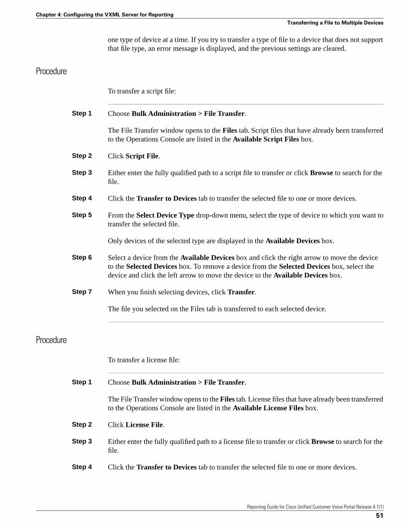
one type of device at a time. If you try to transfer a type of file to a device that does not supportthat file type, an error message is displayed, and the previous settings are cleared.
Procedure
To transfer a script file:
Step 1 Choose Bulk Administration > File Transfer.
The File Transfer window opens to the Files tab. Script files that have already been transferredto the Operations Console are listed in the Available Script Files box.
Step 2 Click Script File.
Step 3 Either enter the fully qualified path to a script file to transfer or click Browse to search for thefile.
Step 4 Click the Transfer to Devices tab to transfer the selected file to one or more devices.
Step 5 From the Select Device Type drop-down menu, select the type of device to which you want totransfer the selected file.
Only devices of the selected type are displayed in the Available Devices box.
Step 6 Select a device from the Available Devices box and click the right arrow to move the deviceto the Selected Devices box. To remove a device from the Selected Devices box, select thedevice and click the left arrow to move the device to the Available Devices box.
Step 7 When you finish selecting devices, click Transfer.
The file you selected on the Files tab is transferred to each selected device.
Procedure
To transfer a license file:
Step 1 Choose Bulk Administration > File Transfer.
The File Transfer window opens to the Files tab. License files that have already been transferredto the Operations Console are listed in the Available License Files box.
Step 2 Click License File.
Step 3 Either enter the fully qualified path to a license file to transfer or click Browse to search for thefile.
Step 4 Click the Transfer to Devices tab to transfer the selected file to one or more devices.
Reporting Guide for Cisco Unified Customer Voice Portal Release 4.1(1)
51
Chapter 4: Configuring the VXML Server for Reporting
Transferring a File to Multiple Devices

Step 5 From the Select Device Type drop-down menu, select the type of device to which you want totransfer the selected file.
Only devices of the selected type are displayed in the Available Devices box.
Step 6 Select a device from the Available Devices box and click the right arrow to move the deviceto the Selected Devices box. To remove a device from the Selected Devices box, select thedevice and click the left arrow to move the device to the Available Devices box.
Step 7 When you finish selecting devices, click Transfer.
The file you selected on the Files tab is transferred to each selected device.
Reporting Guide for Cisco Unified Customer Voice Portal Release 4.1(1)
52
Chapter 4: - Configuring the VXML Server for Reporting
Transferring a File to Multiple Devices

Introduction to the Database SchemaThis section contains the following topics:
• About the Database Schema, page 53• Entity-Relationship Diagram, page 54• Table Definitions, page 54
About the Database Schema
The Reporting Server hosts an Informix Dynamic Server (IDS) database, where it stores reportingdata in a defined database schema. The schema is fully published so that customers may developcustom reports based on it, using a customer-provided report presentation product. (Customersmay not, however, extend the schema for their own purposes.)
This schema provides Unified CVP customers with the ability to:
• establish database connectivity with commercial off-the-shelf reporting and analytics enginesfrom popular business intelligence technology vendors, such as Crystal Reports andExony—and then build their custom reporting and analytics solutions against the UnifiedCVP database schema
• join with an ICM HDS database to track call activity across both systems (see "Joining Datawith an ICM HDS Database" (page 85))
The following diagram indicates a common set of incoming and outgoing entry and exit statesfor a call to a self-service application.
Reporting Guide for Cisco Unified Customer Voice Portal Release 4.1(1)
53
Chapter 5

Figure 2: Call Flow
Entity-Relationship Diagram
The following ER diagram shows the Unified CVP database schema.
Figure 3: ER Diagram
Table Definitions
This section lists all the tables, in alphabetical order.
Reporting Guide for Cisco Unified Customer Voice Portal Release 4.1(1)
54
Chapter 5: - Introduction to the Database Schema
Entity-Relationship Diagram

ActionTypeRef Table
This is the table to map an ActionTypeID to the type of action for an element that changes data.
DescriptionIndexNullTypeField
The unique id of anaction type
Yes (Primary Key)NointActionTypeID
The name of the actiontype
NoNonvarchar(96)Name
Table Values (ID, Name):
1, "Initialize"
2, "Update"
3, "Return"
Call Table
This table contains one record per call.
DescriptionIndexNullTypeField
The global unique id ofa call
Yes (Primary KeyComposite CallGUID,CallStartDate)
Nochar(35)CallGUID
Date of the call, fordata purging purposes
Yes (Primary KeyComposite CallGUID,CallStartDate)
NodateCallStartDate
Date and time a callwas made
YesNodatetimeStartDateTime
The name of the CallServer (its message
NoNovarchar(42)MessageBusName
adapter name) wherethe call originates
The type of UnifiedCVP Service, such asSIP, IVR, VXML
NoNointSubSystemTypeID
The local time zoneidentifier
NoYesintLocalTimeZone
ANI of the caller sentby telephony provider
NoNovarchar(32)ANI
DNIS of a call sent bytelephony provider
NoNovarchar(32)DNIS
Reporting Guide for Cisco Unified Customer Voice Portal Release 4.1(1)
55
Chapter 5: Introduction to the Database Schema
Table Definitions

DescriptionIndexNullTypeField
The date and time acall ended with
NoYesdatetimeEndDateTime
hang-up or disconnect(but see the Notebelow)
The UUI of theoriginating caller sentby telephony provider
NoYesvarchar(100)UUI
The IIDIGITS of theoriginating caller sentby telephony provider
NoYesvarchar(100)Iidigits
The external UID ofthe caller if the call isassociated with a user
NoYesvarchar(50)UID
The number ofapplications visited
NoNointNumAppVisited
during the life of thecall
The number of timesthat the call is opt outto an agent
NoNointNumOptOut
The total number oftimes the call istransferred out
NoNointTotalTransfer
The number of timesthe call timed out
NoNointNumTimeOut
The number of errorsthat occurred duringthe call
NoNointNumError
The number of timesthe call is on hold dueto unavailable port
NoNointNumOnHold
The date and time ofthe database operation
NoNodatetimeDBDateTime
Note: On occasion, messages are dropped—even for an otherwise successful call. In such cases,EndDateTime is set to the same value as StartDateTime. Thus, if a call appears to be of 0duration, report writers will know to exclude such a call from consideration in cases where itwould otherwise skew metrics.
Reporting Guide for Cisco Unified Customer Voice Portal Release 4.1(1)
56
Chapter 5: - Introduction to the Database Schema
Table Definitions

CallEvent Table
DescriptionIndexNullTypeField
The global unique id ofa call
Yes (Composite indexCallGUID,CallStartDate)
Nochar(35)CallGUID
Date of the call, fordata purging purposes
Yes (Composite indexCallGUID,CallStartDate)
NodateCallStartDate
A call id assigned by aService
NoYesvarchar(43)CallLegID
The name of the CallServer (its message
NoNovarchar(42)MessageBusName
adapter name) withwhich the event isassociated
Date and time of theevent
YesNodatetimeEventDateTime
The mechanism usedto generate the callevent
NoNointEventTypeID
The reason that the callevent was generated
NoNointCauseID
The date and time ofthe database operation
NoNodatetimeDBDateTime
The type of the ServiceYesNointSubSystemTypeID
The name of theService the eventoriginated from
NoNovarchar(41)SubSystemName
The local time zoneidentifier
NoYesintLocalTimeZone
CallICMInfo Table
DescriptionIndexNullTypeField
The global unique id of a callYes (Compositeindex
Nochar(35)CallGUID
CallGUID,CallStartDate)
Date of the call, for datapurging purposes
Yes (Compositeindex
NodateCallStartDate
CallGUID,CallStartDate)
Reporting Guide for Cisco Unified Customer Voice Portal Release 4.1(1)
57
Chapter 5: Introduction to the Database Schema
Table Definitions

DescriptionIndexNullTypeField
ICM Router CallKeyYesNointRouterCallKey
ICM RouterCallKeyDayYesNointRouterCallKeyDay
ICMRouterCallKeySequenceNumber
YesYesintRouterCallKeySequenceNumber
Date and time of the eventYesNodatetimeEventDateTime
The name of the message busthat delivers the VXMLdatafeed message
NoNovarchar(42)MessageBusName
The date and time of thedatabase operation
NoNodatetimeDBDateTime
CauseRef Table
This is the table to map a CauseID to the cause.
DescriptionIndexNullTypeField
The unique id of a callevent cause
Yes (Primary Key)NointCauseID
The cause of the eventNoNonvarchar(96)Name
Table Values (ID, Name):
0, "None"
1, "Normal Completion"
2, "Call Abandon"
3, "Call Transferred"
4, "New Transaction"
5, "Busy"
6, "No Answer"
7, "Maintenance"
8, "Net Congestion"
9, "Net Not Obtainable"
10, "Reorder Tone"
11, "Resources Not Available"
12, "Trunks Busy"
Reporting Guide for Cisco Unified Customer Voice Portal Release 4.1(1)
58
Chapter 5: - Introduction to the Database Schema
Table Definitions

13, "Called Party Disconnected"
14, "Max Ports"
15, "Suspended"
16, "Time Out"
17, "Invalidated"
18, "Error"
1001, "Hang Up"
1002, " Network"
1003, "System"
1004, "Script Type"
1005, "Unknown UApp"
1006, "Script Name"
1007, "Config Param"
1008, "Misconfig Ecc"
1009, "Media File"
1010, "Semantic"
1011, "VXML Format"
1012, "VXML Element"
1013, "Variable Data"
1014, "No Var Data"
1015, "Format"
1016, "Entry Invalid"
1017, "No Entry"
1020, "Data Range"
1021, "Timed Out"
1022, "Called Hung Up" [agent, VRU, or other endpoint hung up on caller; that is, the callerdid not hang up first]
Reporting Guide for Cisco Unified Customer Voice Portal Release 4.1(1)
59
Chapter 5: Introduction to the Database Schema
Table Definitions
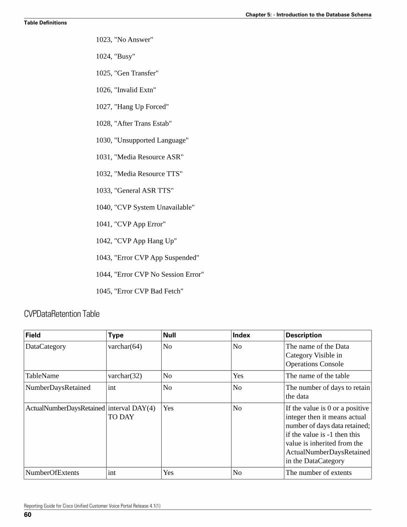
1023, "No Answer"
1024, "Busy"
1025, "Gen Transfer"
1026, "Invalid Extn"
1027, "Hang Up Forced"
1028, "After Trans Estab"
1030, "Unsupported Language"
1031, "Media Resource ASR"
1032, "Media Resource TTS"
1033, "General ASR TTS"
1040, "CVP System Unavailable"
1041, "CVP App Error"
1042, "CVP App Hang Up"
1043, "Error CVP App Suspended"
1044, "Error CVP No Session Error"
1045, "Error CVP Bad Fetch"
CVPDataRetention Table
DescriptionIndexNullTypeField
The name of the DataCategory Visible inOperations Console
NoNovarchar(64)DataCategory
The name of the tableYesNovarchar(32)TableName
The number of days to retainthe data
NoNointNumberDaysRetained
If the value is 0 or a positiveinteger then it means actual
NoYesinterval DAY(4)TO DAY
ActualNumberDaysRetained
number of days data retained;if the value is -1 then thisvalue is inherited from theActualNumberDaysRetainedin the DataCategory
The number of extentsNoYesintNumberOfExtents
Reporting Guide for Cisco Unified Customer Voice Portal Release 4.1(1)
60
Chapter 5: - Introduction to the Database Schema
Table Definitions

DescriptionIndexNullTypeField
The extent space usedNoYesfloatExtentSpaceUsed
The data plus index spacesize used in megabytes
NoYesfloatTotalSpaceUsed
The data space size used inmegabytes
NoYesfloatDataSpaceUsed
The date and time of lastdaily run
NoYesdatetimeDailyPurgeLastRunDate
The date and time of lastemergency purge
NoYesdatetimeEmergencyPurgeLastRunDate
CVPDateTrap Table
DescriptionIndexNullTypeField
Meta for schemamanagement
NoYesdateCallStartDate
CVPDBSpaceUsed Table
DescriptionsIndexNullTypeField
Name of the DBSpaceNoNovarchar(20)DBSpace
Total Available FileSpace
NoNofloatTotalSpace
Reserved SpaceNoNofloatExtendedSpace
Non-reserved SpaceNoNofloatFreeSpace
Amount ofExtendedSpaceactually used
NoYesfloatDataSpaceUsed
Maximum recordedgrowth in 24 hours
NoYesfloatMaxSizeGrowth
Last recorded growthin 24 hours
NoYesfloatRecentSizeGrowth
The date and timewhen the record wasupdated
NoNodatetimeLastRunDate
CVPDBVersion Table
DescriptionIndexNullTypeField
Major versionYes (Composite indexMajorVersion,MinorVersion)
Novarchar(10)MajorVersion
Reporting Guide for Cisco Unified Customer Voice Portal Release 4.1(1)
61
Chapter 5: Introduction to the Database Schema
Table Definitions

DescriptionIndexNullTypeField
Minor versionYes (Composite indexMajorVersion,MinorVersion)
Novarchar(20)MinorVersion
The date and timewhen the record isupdated
NoNodatetimeUpdateDateTime
CVPLog Table
DescriptionIndexNullTypeField
Date and time ofmessage
NoYesdatetimeMessageDateTime
Message detailsNoYesvarchar(255)Message
Type of message: Add,Aged Off, Alter, Err
YesYeschar(8)MessageClass
Info, Remainder,EPurge
CVPPartitionInfo Table
DescriptionIndexNullTypeField
Name of the tableYes (Composite indexTableName, PartDate)
Novarchar(32)TableName
Date of the data inpartition
Yes (Composite indexTableName, PartDate)
NodatePartDate
Name of the partitionNoNochar(12)PartName
The date and time thatthe partition wascreated
NoNodatetimeDBDateTime
CVPPartitionParameters Table
DescriptionIndexNullTypeField
Usable data size in GBNoNointDBSize
Percent of space tokeep free in the DBspace
NoNofloatPCTFree
Planned growth factor,used to determine sizesfor future table extents
NoNofloatBump
Reporting Guide for Cisco Unified Customer Voice Portal Release 4.1(1)
62
Chapter 5: - Introduction to the Database Schema
Table Definitions

DescriptionIndexNullTypeField
Number of days aheadto create partitions;minimum is 1
NoNointDaysAhead
Starting size in KB forlarge sized tables
NoNointContainerSizeLarge
Starting size in KB formedium sized tables
NoNointContainerSizeMedium
Starting size in KB forsmall sized tables
NoNointContainerSizeSmall
CVPPurgeList Table
DescriptionIndexNullTypeField
Action to take: A=Add,D=Drop, S=Split
NoYeschar(1)Action
Name of tableNoYesvarchar(32)TableName
ID of tableNoYesintTabID
Name of the partitionNoYeschar(12)Partition
Date of the data inpartition
NoYesdatePartDate
Name of the DB spaceNoYesvarchar(32)DBSpace
Size of the partitionNoYesintPartSize
Reason for the actionNoYeschar(12)Reason
ElementTypeRef Table
This is the table to map an ElementTypeID to a VXML element type.
DescriptionIndexNullTypeField
The unique id of anelement type
Yes (Primary Key)NointElementTypeID
The name of theelement type
NoNonvarchar(96)Name
Table Values (ID, Name):
0, "Start"
1, "End"
2, "Subdialog_Start"
3, "Subdialog_Return"
Reporting Guide for Cisco Unified Customer Voice Portal Release 4.1(1)
63
Chapter 5: Introduction to the Database Schema
Table Definitions
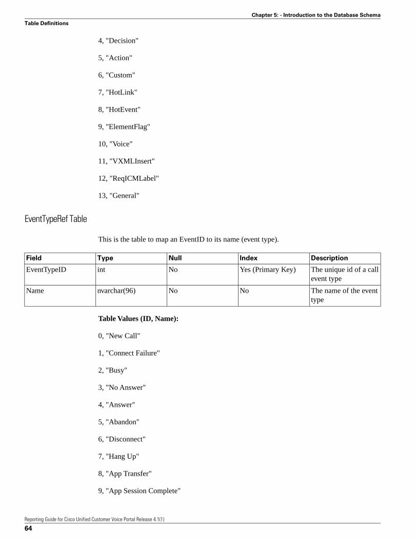
4, "Decision"
5, "Action"
6, "Custom"
7, "HotLink"
8, "HotEvent"
9, "ElementFlag"
10, "Voice"
11, "VXMLInsert"
12, "ReqICMLabel"
13, "General"
EventTypeRef Table
This is the table to map an EventID to its name (event type).
DescriptionIndexNullTypeField
The unique id of a callevent type
Yes (Primary Key)NointEventTypeID
The name of the eventtype
NoNonvarchar(96)Name
Table Values (ID, Name):
0, "New Call"
1, "Connect Failure"
2, "Busy"
3, "No Answer"
4, "Answer"
5, "Abandon"
6, "Disconnect"
7, "Hang Up"
8, "App Transfer"
9, "App Session Complete"
Reporting Guide for Cisco Unified Customer Voice Portal Release 4.1(1)
64
Chapter 5: - Introduction to the Database Schema
Table Definitions

10, "Call Transfer"
11, "Run Script"
OutgoingECCVariable Table
DescriptionIndexNullTypeField
The global unique id ofa call
Yes (Composite indexCallGUID,CallStartDate)
Nochar(35)CallGUID
Date of the call, fordata purging purposes
Yes (second field inComposite indexes)
NodateCallStartDate
The identifier of thesession in which theECC variable changes
Yes (Composite indexSessionID,CallStartDate)
Noint8SessionID
The identifier of theelement in which theECC variable changes
Yes (Composite indexElementID,CallStartDate)
Noint8ElementID
The name of sessionvariable that was exited
NoNochar(12)ECCVarName
The value of sessionvariable
NoNonvarchar(255)ECCVarValue
Date and time when theECC variable changed
YesNodatetimeEventDateTime
The name of themessage bus that
NoNovarchar(42)MessageBusName
delivers the VXMLdatafeed message
The date and time ofthe database operation
NoNodatetimeDBDateTime
ResultRef Table
This is the table to map a ResultID to a result string.
DescriptionIndexNullTypeField
The unique id of aresult
Yes (Primary Key)NointResultID
The name of theelement result
NoNonvarchar(96)Name
Table Values (ID, Name):
1, "Normal"
Reporting Guide for Cisco Unified Customer Voice Portal Release 4.1(1)
65
Chapter 5: Introduction to the Database Schema
Table Definitions

2, "Invalidated"
3, "HotEvent"
4, "HotLink"
5, "Hang Up"
6, "Error"
7, "Transfer"
SubSystemTypeRef Table
This is the table to map a SubSystemTypeID to a Unified CVP Service type.
DescriptionIndexNullTypeField
The unique id of aService type
Yes (Primary Key)NointSubSystemTypeID
The name of theService type
NoNonvarchar(96)Name
Table Values (ID, Name):
0, "SIP"
1, "IVR"
2, "VXML"
3, "OAMP" [Operate, Administer, Maintain, Provision = Operations Console]
4, "CONTROLLER"
5, "RPT"
6, "ICM"
7, "ORM" [OAMP Resource Manager = element co-located with Unified CVP components thatallows the Operations Console to manage the components]
8, "SYSTEM"
UserInputModeRef Table
This is the table to map a UserInputModeID to the name of the user input mode.
Reporting Guide for Cisco Unified Customer Voice Portal Release 4.1(1)
66
Chapter 5: - Introduction to the Database Schema
Table Definitions
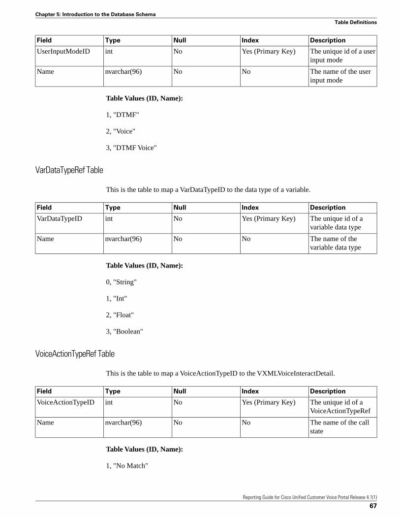
DescriptionIndexNullTypeField
The unique id of a userinput mode
Yes (Primary Key)NointUserInputModeID
The name of the userinput mode
NoNonvarchar(96)Name
Table Values (ID, Name):
1, "DTMF"
2, "Voice"
3, "DTMF Voice"
VarDataTypeRef Table
This is the table to map a VarDataTypeID to the data type of a variable.
DescriptionIndexNullTypeField
The unique id of avariable data type
Yes (Primary Key)NointVarDataTypeID
The name of thevariable data type
NoNonvarchar(96)Name
Table Values (ID, Name):
0, "String"
1, "Int"
2, "Float"
3, "Boolean"
VoiceActionTypeRef Table
This is the table to map a VoiceActionTypeID to the VXMLVoiceInteractDetail.
DescriptionIndexNullTypeField
The unique id of aVoiceActionTypeRef
Yes (Primary Key)NointVoiceActionTypeID
The name of the callstate
NoNonvarchar(96)Name
Table Values (ID, Name):
1, "No Match"
Reporting Guide for Cisco Unified Customer Voice Portal Release 4.1(1)
67
Chapter 5: Introduction to the Database Schema
Table Definitions

2, "No Input"
3, "Audio Group"
4, "Input Mode"
5, "Utterance"
6, "Interpretation"
7, "Confidence"
VXMLCustomContent Table
This table contains one record for each VoiceXML custom event. This event will occur if acustom component programmatically calls the addToLog method of the Session API. The eventwill also occur when an element whose configuration contains entries in the Add To Log tablein the General tab is run.
DescriptionIndexNullTypeField
The unique id of avisited element
Yes (Composite indexElementID,CallStartDate)
Noint8ElementID
Date of the call, fordata purging purposes
Yes (Composite indexElementID,CallStartDate)
NodateCallStartDate
The name of thecustom event variable
NoNonvarchar(51)VarName
The value of thecustom event variable
NoYesnvarchar(255)VarValue
Date and time when thevariable is changed
NoNodatetimeEventDateTime
The name of themessage bus that
NoNovarchar(42)MessageBusName
delivers the VXMLdatafeed message
The date and time ofthe database operation
NoNodatetimeDBDateTime
VXMLElement Table
This table contains one record for each VoiceXML script element visited by a call. For example,if the same element is visited twice in an application script during a call, there will be twoseparate element records.
Reporting Guide for Cisco Unified Customer Voice Portal Release 4.1(1)
68
Chapter 5: - Introduction to the Database Schema
Table Definitions
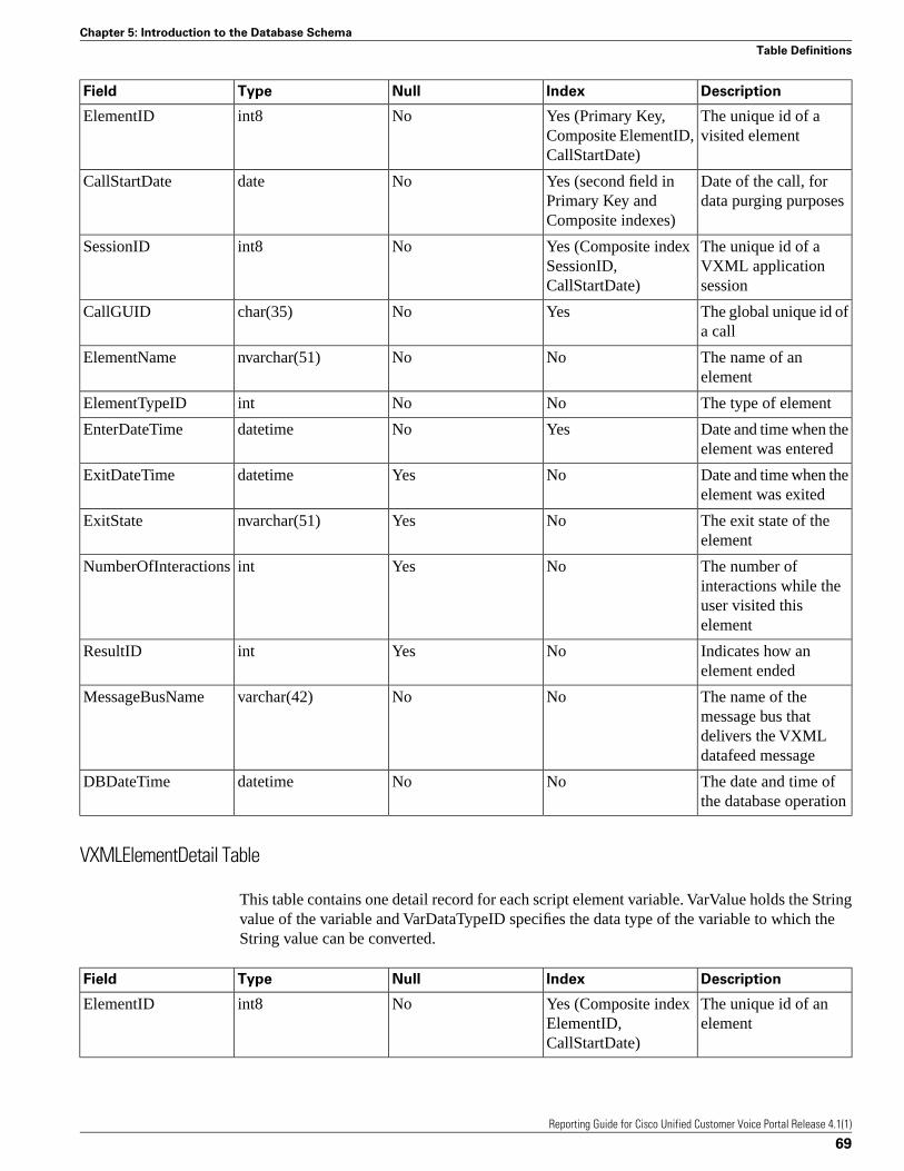
DescriptionIndexNullTypeField
The unique id of avisited element
Yes (Primary Key,Composite ElementID,CallStartDate)
Noint8ElementID
Date of the call, fordata purging purposes
Yes (second field inPrimary Key andComposite indexes)
NodateCallStartDate
The unique id of aVXML applicationsession
Yes (Composite indexSessionID,CallStartDate)
Noint8SessionID
The global unique id ofa call
YesNochar(35)CallGUID
The name of anelement
NoNonvarchar(51)ElementName
The type of elementNoNointElementTypeID
Date and time when theelement was entered
YesNodatetimeEnterDateTime
Date and time when theelement was exited
NoYesdatetimeExitDateTime
The exit state of theelement
NoYesnvarchar(51)ExitState
The number ofinteractions while the
NoYesintNumberOfInteractions
user visited thiselement
Indicates how anelement ended
NoYesintResultID
The name of themessage bus that
NoNovarchar(42)MessageBusName
delivers the VXMLdatafeed message
The date and time ofthe database operation
NoNodatetimeDBDateTime
VXMLElementDetail Table
This table contains one detail record for each script element variable. VarValue holds the Stringvalue of the variable and VarDataTypeID specifies the data type of the variable to which theString value can be converted.
DescriptionIndexNullTypeField
The unique id of anelement
Yes (Composite indexElementID,CallStartDate)
Noint8ElementID
Reporting Guide for Cisco Unified Customer Voice Portal Release 4.1(1)
69
Chapter 5: Introduction to the Database Schema
Table Definitions

DescriptionIndexNullTypeField
Date of the call, fordata purging purposes
Yes (Composite indexElementID,CallStartDate)
NodateCallStartDate
The name of theelement variable
NoNonvarchar(51)VarName
The String value of theelement variable
NoYesnvarchar(255)VarValue
The data type of theelement variable, such
NoNointVarDataTypeID
as String, Integer,Boolean
The type of action foran element thatchanges data
NoNointActionTypeID
Date and time when thevariable was changed
YesNodatetimeEventDateTime
The name of themessage bus that
NoNovarchar(42)MessageBusName
delivers the VXMLdatafeed message
The date and time ofthe database operation
NoNodatetimeDBDateTime
VXMLElementFlag Table
DescriptionIndexNullTypeField
The unique id for theelement in which theflag activated
Yes (Composite indexElementID,CallStartDate)
Noint8ElementID
Date of the call, fordata purging purposes
Yes (Composite indexElementID,CallStartDate)
NodateCallStartDate
The date and timewhen the flag activated
YesNodatetimeEventDateTime
The flag nameNoNonvarchar(51)Name
Name of the previousapplication element
NoYesnvarchar(51)PreviousElementName
The name of themessage bus that
NoNovarchar(42)MessageBusName
delivers the VXMLdatafeed message
The date and time ofthe database operation
NoNodatetimeDBDateTime
Reporting Guide for Cisco Unified Customer Voice Portal Release 4.1(1)
70
Chapter 5: - Introduction to the Database Schema
Table Definitions

VXMLError Table
DescriptionIndexNullTypeField
The unique id for theelement in which theerror occurs
Yes (Composite indexElementID,CallStartDate)
Noint8ElementID
Date of the call, fordata purging purposes
Yes (Composite indexElementID,CallStartDate)
NodateCallStartDate
Name of an errorNoNovarchar(12)ErrorName
The date and timewhen the erroroccurred
YesNodatetimeEventDateTime
The detailed errormessage
NoNonvarchar(255)Description
The name of themessage bus that
NoNovarchar(42)MessageBusName
delivers the VXMLdatafeed message
The date and time ofthe database operation
NoNodatetimeDBDateTime
VXMLHotEvent Table
DescriptionIndexNullTypeField
The unique id for theelement in which thehotevent occurred
Yes (Composite indexElementID,CallStartDate)
Noint8ElementID
Date of the call, fordata purging purposes
Yes (Composite indexElementID,CallStartDate)
NodateCallStartDate
The date and timewhen hot eventoccurred
YesNodatetimeEventDateTime
The name of the hotevent
NoNonvarchar(51)Name
The name of themessage bus that
NoNovarchar(42)MessageBusName
delivers the VXMLdatafeed message
The date and time ofthe database operation
NoNodatetimeDBDateTime
Reporting Guide for Cisco Unified Customer Voice Portal Release 4.1(1)
71
Chapter 5: Introduction to the Database Schema
Table Definitions

VXMLHotLink Table
DescriptionIndexNullTypeField
The unique id for theelement in which thehotlink activated
Yes (Composite indexElementID,CallStartDate)
Noint8ElementID
Date of the call, fordata purging purposes
Yes (Composite indexElementID,CallStartDate)
NodateCallStartDate
The date and timewhen the hot linkactivated
YesNodatetimeEventDateTime
The name of the hotlink
NoNonvarchar(51)Name
The name of themessage bus that
NoNovarchar(42)MessageBusName
delivers the VXMLdatafeed message
The date and time ofthe database operation
NoNodatetimeDBDateTime
VXMLSession Table
This table contains one record for each application visited by a call. For example, if a call hastransferred from one application to another one, the call with the same CallGUID will have twosession records.
DescriptionIndexNullTypeField
The unique id of aVXML applicationsession
Yes (Primary Key,Composite SessionID,CallStartDate)
Noint8SessionID
Date of the call, fordata purging purposes
Yes (second field inPrimary Key andComposite indexes)
NodateCallStartDate
The name of thesession assigned byVXML Server
NoNonvarchar(96)SessionName
The global unique id ofa call
Yes (Composite indexCallGUID,CallStartDate)
Nochar(35)CallGUID
Date and time whensession starts
YesNodatetimeStartDateTime
The name of theVXML application
YesNonvarchar(51)AppName
Reporting Guide for Cisco Unified Customer Voice Portal Release 4.1(1)
72
Chapter 5: - Introduction to the Database Schema
Table Definitions
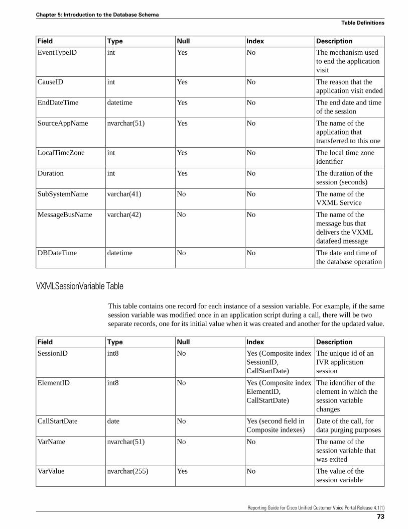
DescriptionIndexNullTypeField
The mechanism usedto end the applicationvisit
NoYesintEventTypeID
The reason that theapplication visit ended
NoYesintCauseID
The end date and timeof the session
NoYesdatetimeEndDateTime
The name of theapplication thattransferred to this one
NoYesnvarchar(51)SourceAppName
The local time zoneidentifier
NoYesintLocalTimeZone
The duration of thesession (seconds)
NoYesintDuration
The name of theVXML Service
NoNovarchar(41)SubSystemName
The name of themessage bus that
NoNovarchar(42)MessageBusName
delivers the VXMLdatafeed message
The date and time ofthe database operation
NoNodatetimeDBDateTime
VXMLSessionVariable Table
This table contains one record for each instance of a session variable. For example, if the samesession variable was modified once in an application script during a call, there will be twoseparate records, one for its initial value when it was created and another for the updated value.
DescriptionIndexNullTypeField
The unique id of anIVR applicationsession
Yes (Composite indexSessionID,CallStartDate)
Noint8SessionID
The identifier of theelement in which the
Yes (Composite indexElementID,CallStartDate)
Noint8ElementID
session variablechanges
Date of the call, fordata purging purposes
Yes (second field inComposite indexes)
NodateCallStartDate
The name of thesession variable thatwas exited
NoNonvarchar(51)VarName
The value of thesession variable
NoYesnvarchar(255)VarValue
Reporting Guide for Cisco Unified Customer Voice Portal Release 4.1(1)
73
Chapter 5: Introduction to the Database Schema
Table Definitions

DescriptionIndexNullTypeField
The type of action fora session variable thatchanges data
NoNointActionTypeID
Date and time when thesession variablechanged
YesNodatetimeEventDateTime
The data type of thesession variable, such
NoNointVarDataTypeID
as Integer, String,Boolean
The name of themessage bus that
NoNovarchar(42)MessageBusName
delivers the VXMLdatafeed message
The date and time ofthe database operation
NoNodatetimeDBDateTime
Indicates whether thissession variable change
NoNobooleanFromICM
originated fromUnified ICME;Informix stores thesevalues as 1 or 0, butrepresents these valuesas 't' or 'f'
VXMLVoiceInteractDetail Table
DescriptionIndexNullTypeField
The unique id of avisited element
Yes (Composite indexElementID,CallStartDate)
Noint8ElementID
Date of the call, fordata purging purposes
Yes (Composite indexElementID,CallStartDate)
NodateCallStartDate
Time since the lastinteraction
NoNointElapsedTimeMillisecond
Type of interactionNoNointVoiceActionTypeID
Value of interactionNoYesnvarchar(255)Value
The date and time ofthe database operation
NoNodatetimeDBDateTime
Reporting Guide for Cisco Unified Customer Voice Portal Release 4.1(1)
74
Chapter 5: - Introduction to the Database Schema
Table Definitions
Reporting Against the DatabaseUnified CVP does not provide a native reporting engine. A third-party reporting engine, suchas Crystal Reports, can be used to generate various reports against the predefined Unified CVPdatabase schema. Unified CVP does provide, as examples, a few sample report templates. Thischapter discusses the various sample report templates.
Using the Cisco-Provided Sample Report Templates
Unified CVP provides a few sample Crystal Reports templates, as well as the SQL statementsused in the reports. This may make it easier for you to generate customized reports with yourown reporting tools.
Thus, these samples can be used in three ways:
• As is, if you are using Crystal Reports and these templates meet your needs
• As a foundation that you can alter to create Crystal Report templates that better suit yourneeds
• As examples of report templates that you can use to guide you in creating report templatesfor whatever report engine you are using
The templates can be run using Crystal Reports or a Crystal Viewer. Either of these wouldexecute the sample templates to query against the reporting database. The sample reports arebased on data that was generated by sample VoiceXML scripts. These sample scripts are shippedwith the Reporting Server so that you can run the scripts to generate data and then run the samplereports. The SQL statements used by Crystal Reports are also provided.
Note: Sample templates are available on the Cisco Unified CVP Release 4.1(1) Software CD,in a top-level directory called Samples. The templates are installed on the Reporting Server.The sample scripts, and the SQL statements, are also provided in the Samples directory.
Reporting Guide for Cisco Unified Customer Voice Portal Release 4.1(1)
75
Chapter 6

Unified CVP Call Summary Report
The Reporting Service captures and presents detailed data on every call made to the Call Server.It traces the path of each call through the entire distributed self-service application using uniquecall identifiers, the various applications (and/or system components) that a particular call visited,when the applications (and/or system components) were visited, and the total number of callsthat the Call Server was processing at that time.
Table 10: Unified CVP Call Summary Report
Total
Transfers
Num
Apps
Visited
Num
Errors
Num
Time Out
DNISANICall
Duration
TimeStart
Date
CallGUIDCall
Num
01003110190190190500:40:4511/30/200628CD4191-7F6C11DB-
1
A6EF0014-6944B976
01003110190190190500:40:4711/30/20062A288BE4-7F6C11DB-
2
A6F00014-6944B976
01003110191191191500:40:4811/30/20062AC38680-7F6C11DB-
3
900D0014-6944B962
01003110190190190500:40:5011/30/20062BF25095-7F6C11DB-
4
A6F10014-6944B976
100080014310011140:40:5011/30/20062BFA1D3C-7F6C11DB-
5
82AB0014-6944B8CC
01003110191191191500:40:5111/30/20062C61F58D-7F6C11DB-
6
900E0014-6944B962
2100800143100111300:40:5311/30/20062D685567-7F6C11DB-
7
82AC0014-6944B8CC
01003110190190190500:40:5311/30/20062DBC1546-7F6C11DB-
8
A6F20014-6944B976
Reporting Guide for Cisco Unified Customer Voice Portal Release 4.1(1)
76
Chapter 6: - Reporting Against the Database
Using the Cisco-Provided Sample Report Templates

Total
Transfers
Num
Apps
Visited
Num
Errors
Num
Time Out
DNISANICall
Duration
TimeStart
Date
CallGUIDCall
Num
01003110191191191500:40:5411/30/20062E2D8EB6-7F6C11DB-
9
900F0014-6944B962
Unified CVP Application Summary Report
To measure the overall effectiveness of various self-service applications, the application summaryreport displays the core application data.
Table 11: Unified CVP Application Summary Report
Caller AbandonHandledOfferedGroup Name
1,6203,248,2813,276,239Reporting GD DTMF 60sec
Unified CVP VXML Element By Call Report
Customers who deploy self-service applications need a report that tracks a call's path throughVXML elements. This report is used to debug and monitor VXML applications after they aredeployed.
Table 12: Unified CVP VXML Element By Call Report
Element TypeElement Exit TimeElement Enter TimeElement Name
Subdialog Start1:11:53 am1:11:53 amSubdialog Start 01
Start1:11:53 am1:11:53 amstart
ReqICMLabel1:11:54 am1:11:53 amReqICMLabel
ElementFlag1:11:54 am1:11:54 amFlag Done
Voice1:11:54 am1:11:54 amAudio Exit
Voice1:11:54 am1:11:54 amAudio ValidLabel
Subdialog Return1:11:54 am1:11:54 amSubdialog Return 01
End1:12:43 am1:12:43 amend
Unified CVP and Unified ICME Report
Customers who deploy self-service applications with their Unified ICME or Unified CCE systemneed a report that will track the details of this system as well as Unified CVP details. CrystalReports can join data from more than one ODBC connection. In particular, Crystal Reportsfunctionality allows you to select two data sources (in this case, one from Unified CVP Informixtables and one from Microsoft SQL Server tables) and create a join report.
Reporting Guide for Cisco Unified Customer Voice Portal Release 4.1(1)
77
Chapter 6: Reporting Against the Database
Using the Cisco-Provided Sample Report Templates

The report discussed here is designed to only return data from one call at a time. The user isprompted to enter the RouterCallKey and the RouterCallKeyDay when launching the report.All of the Unified ICME data originates from the Termination_Call_Detail table. This is a verylarge table and the report must do a sequential scan to retrieve the data as the RouterCallKeyand the RouterCallKeyDay are not indexed columns. To minimize the effect on the HDS youshould run the report during off-hours, or run against an HDS that does not support concurrentreporting users.
Table 13: CallGUID: F772B308-0808927
NumberApps
Visited
DNISANIRouter CallKeyRouter
CallKeyDay
End Date TimeStart DateTime
0830555893197893600003121591207/5/20062:30:23PM
7/5/20062:28:23PM
Table 14: CallGUID: F772B308-0808927
Answered Within
ServiceLevel
Agent Skill
TargetID
Service Skill
TargetID
CallTypeIDDateTimeTCD Record
NNoneNone50017/5/20062:39:23PM
1
N5002500150017/5/20062:30:23PM
2
Running Crystal Reports Templates
To run Crystal Reports templates, you must replace the ODBC connection with a localconnection. Do not install a reporting package on the Reporting Server. Select a machine thatis not used by Unified CVP to develop and launch reports.
Caution: These steps are only intended for advanced users. More complete documentationis installed with the Crystal reporting product. If you are unfamiliar with how to set upand configure ODBC connections, please refer to the Crystal Reports documentation.
To change a template's ODBC connection, perform the following steps:
1. Install Crystal Reports or a Crystal Viewer.
2. Install the Informix ODBC driver, which is included in the CSDK installer. The driver isalso available on the IBM web site.
3. Configure an ODBC connection to point to the Unified CVP Informix Server. Configurea SQL Server connection to an HDS if required.
4. Open the template in Crystal Reports.
5. From the Database menu, choose Set Data Source Location.
6. In the Replace with window, perform the following steps to open a connection:
Reporting Guide for Cisco Unified Customer Voice Portal Release 4.1(1)
78
Chapter 6: - Reporting Against the Database
Using the Cisco-Provided Sample Report Templates
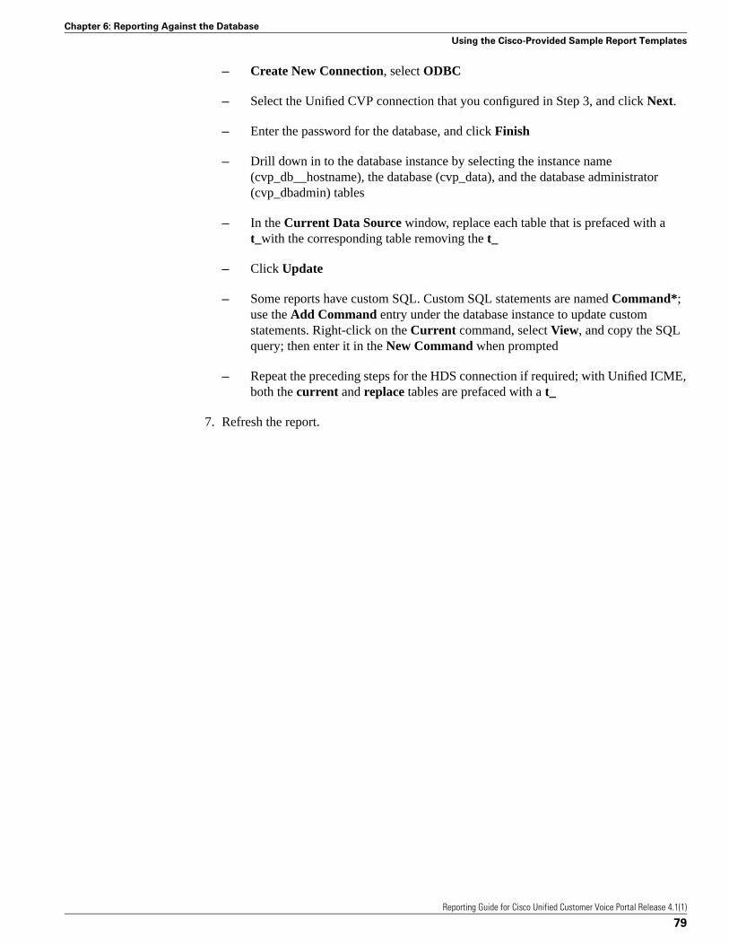
– Create New Connection, select ODBC
– Select the Unified CVP connection that you configured in Step 3, and click Next.
– Enter the password for the database, and click Finish
– Drill down in to the database instance by selecting the instance name(cvp_db__hostname), the database (cvp_data), and the database administrator(cvp_dbadmin) tables
– In the Current Data Source window, replace each table that is prefaced with at_with the corresponding table removing the t_
– Click Update
– Some reports have custom SQL. Custom SQL statements are named Command*;use the Add Command entry under the database instance to update customstatements. Right-click on the Current command, select View, and copy the SQLquery; then enter it in the New Command when prompted
– Repeat the preceding steps for the HDS connection if required; with Unified ICME,both the current and replace tables are prefaced with a t_
7. Refresh the report.
Reporting Guide for Cisco Unified Customer Voice Portal Release 4.1(1)
79
Chapter 6: Reporting Against the Database
Using the Cisco-Provided Sample Report Templates
Reporting Guide for Cisco Unified Customer Voice Portal Release 4.1(1)
80
Chapter 6: - Reporting Against the Database
Using the Cisco-Provided Sample Report Templates

Reporting Best PracticesThis section contains the following topics:
• CPU Intensive Reports, page 81• Filtering Data to be Stored in the Database, page 82• ECC Variable Security, page 82• Writing Efficient SQL when Creating Reports, page 83• Database Sizing Issues, page 83• Database Backup and Recovery, page 84• Only Use Reporting Users when Querying the Database, page 84• Informix, Operating System Time, and Local Time, page 84• Assuring Accurate Time Stamps for Reporting and Logging, page 84• Passwords, page 84• Joining Data with an ICM HDS Database, page 85• Joining Unified CVP and SQL Server Data, page 85• Reporting Isolation Level, page 85• Database Retention Settings, page 85• Purge and Backup Database Maintenance Tasks, page 85• Zero Duration Calls and Writing Reports, page 86
CPU Intensive Reports
Do not run CPU intensive reports off the database while the database is receiving data.
Note: Reports become more CPU intensive as the complexity associated with producing thereport from the information available in the database increases. There is no sharp dividing linebetween intensive and non-intensive reports. The system performance must remain within theguidelines defined in the Cisco Unified Customer Voice Portal (CVP) Release 4.0 SolutionReference Network Design (SRND) document.
Reporting Guide for Cisco Unified Customer Voice Portal Release 4.1(1)
81
Chapter 7
Filtering Data to be Stored in the Database
Users can reduce the data generated by means of data filters (for VXML Server applicationdetail data filtering, see Chapter 4, "Configuring the VXML Server for Reporting" (page 43)).Either adding more exclusive filters, or using fewer inclusive filters, would cut down on theamount of data stored.
ECC Variable Security
Unified CVP offers administrators the ability to choose not to persist sensitive ECC data in thedatabase. Users define ECC variables in Unified ICME and by default they are not persisted inthe Unified CVP database.
The Caller_input and FromExtVXML ECC variables are subject to many application-dependentuses. For security purposes, flag these two variables as not persistent in Unified ICME 7.1(1).If there is anything in them that must be stored, the routing script can copy the data to anappropriate variable for storage in the database.
Additionally, the VXML Server allows you to filter out sensitive data, see Chapter 4,"Configuring the VXML Server for Reporting" (page 43).
Reporting Guide for Cisco Unified Customer Voice Portal Release 4.1(1)
82
Chapter 7: - Reporting Best Practices
Filtering Data to be Stored in the Database

Writing Efficient SQL when Creating Reports
The following guidelines should be kept in mind.
• When writing SQL, developers must organize their WHERE clauses and put the mostimportant join first. The most important join is the one that will reduce the size of the datasetto the least amount of rows.
• Reports must be written so that every field in the WHERE and ORDER BY clauses uses anindexed field.
• The second column in a composite index should never be used in a JOIN statement withoutthe first column.
• Engineers writing database code should treat database, table, and column names as casesensitive, even though the current database is case insensitive, to ensure that the applicationis portable.
• Many operations hold database locks; therefore, reports should use a wait time of 30 seconds,if possible.
• Reports and SQL queries should set Isolation level to dirty read. This is much more efficientfor the database as it utilizes Informix Virtual shared memory instead of the resident memoryportion of shared memory.
• Do not ever set isolation level to repeatable read.
• Do not ever write a SQL statement that selects into temp without specifying the 'no log'option.
• The internal ID generator limits the amount of total VXML subsystems to 8,000 perdeployment.
Database Sizing Issues
See the discussion in "Data Retention" (page 10). Also see the Planning Guide for Cisco UnifiedCustomer Voice Portal and the Cisco Unified Customer Voice Portal (CVP) Release 4.0 SolutionReference Network Design (SRND) document.
Reporting Guide for Cisco Unified Customer Voice Portal Release 4.1(1)
83
Chapter 7: Reporting Best Practices
Writing Efficient SQL when Creating Reports
Database Backup and Recovery
Issues to keep in mind are:
• Managing your backup strategy
• Turning off Reporting Server when doing database recovery
These are discussed in "Database Backup" (page 12) and "Database Recovery" (page 14).
Only Use Reporting Users when Querying the Database
In the interests of security, allow only reporting users to generate reports.
Informix, Operating System Time, and Local Time
Informix only displays a datetime that corresponds to the same time zone as the Informix serveroperating system's time zone. As a result, two items must be kept in mind:
• If you wish a datetime to be displayed for a time zone other than that of the Informix serveroperating system, you must use reporting tools or SQL tools (for example, those availablewith Crystal Reports or Java) to do this.
• If, in your system, you are using more than one Informix server for Unified CVP reporting,it is best if all such server OSs are set to the same time zone. This helps avoid confusion.
Assuring Accurate Time Stamps for Reporting and Logging
Unified CVP components do not themselves synchronize machine times. However, customersmust provide a cross-component time synchronization mechanism, such as NTP, to ensureaccurate time stamps for reporting and logging.
Passwords
Note: Passwords on the Reporting Server must be created as part of the Unified CVP installationor by means of the Operations Console. Updating of passwords must be done via the OperationsConsole. Do not use any other means to create or update passwords.
Reporting passwords are subject to both the Unified CVP password policy and the passwordpolicy enforced by the operating system of the computer on which the Reporting Server resides.
Reporting Guide for Cisco Unified Customer Voice Portal Release 4.1(1)
84
Chapter 7: - Reporting Best Practices
Database Backup and Recovery

For each aspect of the password, the Reporting password must meet the requirement of the morerestrictive policy.
Joining Data with an ICM HDS Database
Joining Unified CVP and Unified ICME data can be a very expensive operation on the UnifiedICME system. To minimize performance impacts on an HDS system, use one of the followingstrategies:
• Dedicate an HDS for these reports
• Query an HDS when Unified ICME reporting users are not running reports
Joining Unified CVP and SQL Server Data
To join data from a SQL Server Database and an Informix Database one must use a reportingtool that supports the ability to join data from two heterogeneous databases.
Reporting Isolation Level
Reporting clients should never run with an isolation level of repeatable read as this could holdlocks and prevent updates to the data.
Database Retention Settings
Ensure that the database is sized conservatively so that it never needs to emergency purge.
Purge and Backup Database Maintenance Tasks
The database backup and purge maintenance tasks are created as Windows Scheduled Tasks,and can be viewed in the Scheduled Tasks window (Start > Programs > Accessories > SystemTools > Scheduled Tasks). These jobs log in as SYSTEM.
If the CVPDBNightlyPurge and CVPDBMidDayPurge tasks do not run, then the database willnot be purged and will eventually become full, resulting in data loss.
If the CVPDBBackup task does not run the database will not be backed up.
Periodically, you should check the Scheduled Tasks to ensure the Last Run Time was as expectedand there are no status messages.
Reporting Guide for Cisco Unified Customer Voice Portal Release 4.1(1)
85
Chapter 7: Reporting Best Practices
Joining Data with an ICM HDS Database

Zero Duration Calls and Writing Reports
On occasion, messages are dropped—even for an otherwise successful call. In such cases,EndDateTime is set to the same value as StartDateTime. Thus, if a call appears to be of 0duration, report writers will know to exclude such a call from consideration in cases where itwould otherwise skew metrics.
Reporting Guide for Cisco Unified Customer Voice Portal Release 4.1(1)
86
Chapter 7: - Reporting Best Practices
Zero Duration Calls and Writing Reports

Index
ActionTypeRef table....55
analytics engine....53
application summary report....77
application user....15
backups....5, 9, 12, 84, 85
cancelling for Reporting Server....28
retries....13
running for Reporting Server....27
before you begin tasks
adding a reporting server....18
adding a VXML Server....43
deleting a Reporting Server....37
editing a VXML Server....45
best practices....81
bulk file transfer
license files....51
script files....51
call
zero duration....86
Call category....12
Call Event category....12
CallEvent table....57
CallICMInfo table....58
Call Server....6
downloading Log Messages XML file....34
uploading Log Messages XML file....33
call summary report....76
Call table....55
CauseRef table....58
configuration tabs
Reporting Server general information....19
Reporting Server Infrastructure Tab....21
Reporting Server reporting properties....20
VXML Server....47
VXML Server properties....46
CPU intensive reports....81
Crystal Reports....7, 53, 75, 78
cvp_dbadmin....15
cvp_dbuser....15
CVPDataRetention table....61
CVPDateTrap table....61
CVPDBSpaceUsed table....61
CVPDBVersion table....62
CVPLogMessages.properties file
editing....35
CVPLogMessages.xml file
editing....35
CVPLog table....62
CVPPartitionInfo table....62
CVPPartitionParameters table....63
CVPPurgeList table....63
database....5, 53
multiple....6
sizing....83, 85
viewing details....31
database administrator....15
database backup (see backups)....12
database connection failure....16
database purge (see purging)....10
database recovery....14, 84
database restore....14
database schema....5, 53
database tables....54
database users (see users)....15
data categories....12
data filtering....82
data retention....10, 61, 85
Reporting Guide for Cisco Unified Customer Voice Portal Release 4.1(1)
Index 87
Index
default number of days....30
destination
log messages....35
device pools
adding or removing a device....41
device statistics
Reporting Server....39
ECC variable....65, 82
ElementTypeRef table....63
emergency purge (see purging)....10
Entity-Relationship diagram....54
ER diagram....54
events
severity levels for....35
EventTypeRef table....64
failure
database connection....16
Reporting Server....16
filtering data....82
filters for reporting
VXML Server....48
generating reports....84
HDS....78, 85
IBM Informix Dynamic Server database (see Informix)..5
ICM....58
ICM Service....6
IDS (see Informix)....5
informix....15
Informix database (see database)....5
Informix user
changing password....24
instance owner....15
isolation level....85
IVR Service....6
join report....77, 85
license files
transferring multiple files....51
log messages
CVPLogMessages.xml....35
Operations Console....9
OutgoingECCVariable table....65
passwords....9
changing reporting database user....24
policies....84
purging....5, 9, 10, 85
emergency....10
number of days to retain data....30
retries....13
purging data....29
querying the database....84
recovery....14
Reporting
configuring Reporting Server....17
reporting database
changing user passwords....24
reporting engine....7, 53, 75
reporting filters
for VXML Server....47
Reporting Server....5, 6
adding....18
adding reporting users....25
cancelling backups....28
changing a reporting user's password....26
changing reporting database user password....24
configuring....17
configuring properties....20
deleting....37
downloading Log Messages XML file....34
editing....23
Reporting Guide for Cisco Unified Customer Voice Portal Release 4.1(1)
Index 88
Index
failure....16
finding....40
general configuration settings....19
infrastructure settings....21
prerequisites for adding....18
prerequisites for deleting....37
removing reporting users....27
running backups....27
running purge....29
statistics....38
uploading Log Messages XMLfile....33
viewing database details....31
viewing statistics....39
Reporting Service....5, 6
reporting users....15
adding....25
changing passwords....26
removing....27
reports
generating....84
report templates....75
resolution
log messages....35
resource properties file
editing....35
restore....14
ResultRef table....65
retries
backup and purge....13
sample report templates....75
schema (see database schema)....5
script files
transferring multiple files....51
severity
log messages....35
of events....35
SIP Service....6
sizing....83, 85
SQL
writing....83
statistics
Reporting Server....38
SubSystemTypeRef table....66
templates....75
time
local....84
stamps....84
system....84
Unified CVP database administrator
changing password....24
Unified CVP user
changing password....24
Unified ICME....78, 85
UserInputModeRef table....66
users....15
adding reporting....25
application user....15
database administrator....15
instance owner....15
reporting user....15
VarDataTypeRef table....67
VoiceActionTypeRef table....67
VoiceML Element Detail category....12
VoiceXML ECC Variable category....12
VoiceXML Element category....12
VoiceXML Interact Detail category....12
VoiceXML Session category....12
VoiceXML Session Variable category....12
VXML
configuring VXML server for reporting....43
Reporting Guide for Cisco Unified Customer Voice Portal Release 4.1(1)
Index 89
Index

VXMLCustomContent table....68
VXML element by call report....77
VXMLElementDetail table....69
VXMLElementFlag table....70
VXMLElement table....68
VXMLError table....71
VXML filters
example wilcards....49
rules....48
VXML Filters
example inclusive and exclusive....49
VXMLHotEvent table....71
VXMLHotLink table....72
VXML Server....6
adding....44
configuration properties....47
configuring for reporting....43
creating reporting filters for....47
downloading Log Messages XML file....34
editing....45
example filter wildcards....49
example reporting filters....49
filters for reporting....48
general configuration settings....46
prerequisites for adding....43
prerequisites for editing....45
rules for reporing filters....48
transferring Log Messages XML file....33
uploading Log Messages XML file....33
VXMLSession table....72
VXMLSessionVariable table....73
VXMLVoiceInteractDetail table....74
zero duration calls....86
Reporting Guide for Cisco Unified Customer Voice Portal Release 4.1(1)
Index 90
Index