reported to - houston no. 1140196201 . ... slide analysis information . ... windermere lane. the...
TRANSCRIPT

GEOTECHNICAL INVESTIGATION
15 WINDERMERE LANE OUTFALL
REPAIR PROJECT
WBS NO. M-000126-0073-3
HOUSTON, TEXAS
Reported to:
UNITED ENGINEERS, INC.
Houston, Texas
Submitted by:
GEOTEST ENGINEERING, INC.
Houston, Texas
REPORT NO. 1140196201
July 18, 2016
Key Map No. 490-U
i
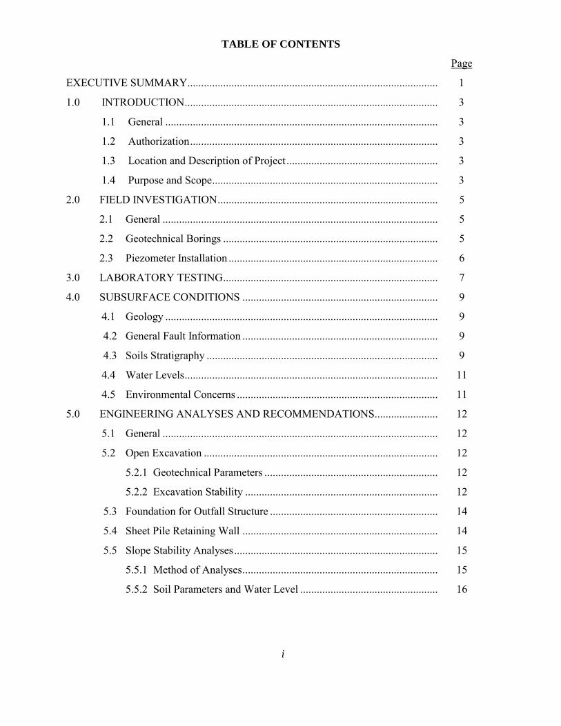
TABLE OF CONTENTS
Page
EXECUTIVE SUMMARY........................................................................................... 1
1.0 INTRODUCTION ............................................................................................ 3
1.1 General ................................................................................................... 3
1.2 Authorization .......................................................................................... 3
1.3 Location and Description of Project ....................................................... 3
1.4 Purpose and Scope .................................................................................. 3
2.0 FIELD INVESTIGATION ................................................................................ 5
2.1 General .................................................................................................... 5
2.2 Geotechnical Borings .............................................................................. 5
2.3 Piezometer Installation ............................................................................ 6
3.0 LABORATORY TESTING .............................................................................. 7
4.0 SUBSURFACE CONDITIONS ....................................................................... 9
4.1 Geology ................................................................................................... 9
4.2 General Fault Information ....................................................................... 9
4.3 Soils Stratigraphy .................................................................................... 9
4.4 Water Levels ............................................................................................ 11
4.5 Environmental Concerns ......................................................................... 11
5.0 ENGINEERING ANALYSES AND RECOMMENDATIONS....................... 12
5.1 General .................................................................................................... 12
5.2 Open Excavation ..................................................................................... 12
5.2.1 Geotechnical Parameters ............................................................... 12
5.2.2 Excavation Stability ...................................................................... 12
5.3 Foundation for Outfall Structure ............................................................. 14
5.4 Sheet Pile Retaining Wall ....................................................................... 14
5.5 Slope Stability Analyses .......................................................................... 15
5.5.1 Method of Analyses ....................................................................... 15
5.5.2 Soil Parameters and Water Level .................................................. 16

ii
TABLE OF CONTENTS (Continued)
Page
5.5.3 Loading Conditions ....................................................................... 17
5.5.4 Factors of Safety ............................................................................ 17
5.6 Excavated Soil for Structural Fill during Construction ........................... 18
5.7 Slope Protection and Erosion Control ..................................................... 18
6.0 CONSTRUCTION CONSIDERATIONS ........................................................ 19
6.1 Sheet Pile Wall and CMP Construction .................................................. 19
6.2 Groundwater Control ............................................................................... 19
6.3 Special Provisions ................................................................................... 19
7.0 LIMITATIONS ................................................................................................. 20
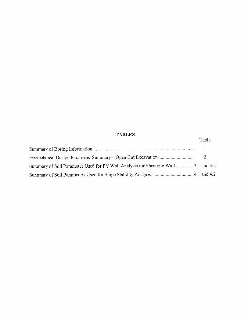
TABLES
Table
Summary of Boring Information ................................................................................... 1
Geotechnical Design Parameter Summary – Open Cut Excavation ............................. 2
Summary of Soil Parameter Used for PY Wall Analysis for Sheetpile Wall ............... 3.1 and 3.2
Summary of Soil Parameters Used for Slope Stability Analyses .................................. 4.1 and 4.2
ILLUSTRATIONS
Figure
Vicinity Map ................................................................................................................. 1
Plan of Borings ............................................................................................................. 2
Boring Log Profile ........................................................................................................ 3
Trench Support Earth Pressures .................................................................................... 4.1 and 4.2
Stability of Bottom for Braced Cut ............................................................................... 5
Axial Pile Capacity Curves ........................................................................................... 6.1 and 6.2
Results of Slope Stability Analysis ............................................................................... 7.1 thru 7.12

iii
TABLE OF CONTENTS (Continued)
APPENDIX A Figure
Log of Borings .............................................................................................................. A-1 thru A-4
Terms Used on Boring Logs ......................................................................................... A-5
Classification of Soils for Engineering Purposes .......................................................... A-6
APPENDIX B Figure
Summary of Laboratory Test Results ............................................................................ B-1 thru B-4
Grain Size Distribution Curves ..................................................................................... B-5 thru B-11
Consolidated Undrained Triaxial Test Report .............................................................. B-12 thru B-14
Permeability Test Results...........................................................................................B-15.1 thru B-15.4
Pinhole and Crumb Test Results ................................................................................... B-16
APPENDIX C
Sheet
Storm Sewer Profile ...................................................................................................... 11 and 13
APPENDIX D
Slide Analysis Information

Geotest Engineering, Inc. Report No. 1140196201
15 Windermere Lane Outfall Repair Project July 18, 2016
WBS No. M-000126-0073-3; Houston, Texas
1
EXECUTIVE SUMMARY
A geotechnical investigation was performed for the design and construction of the Outfall
Repair at 15 Windermere Lane in Houston, Texas. The project site is located behind the property of 15
Windermere Lane at south bank of Buffalo Bayou. The proposed outfall replacement will consist of a
new 32 linear feet of 102-inch diameter corrugated metal pipe (CMP). The proposed CMP invert
elevation will be about El. 27 feet. The channel (Buffalo Bayou) at outfall location will be improved
with the construction of 4H:1V slope with sheet pile wall per City of Houston and/or Harris County
Flood Control District (HCFCD) requirements, which is applicable.
The purposes of this study were to evaluate soil and groundwater conditions and to provide
geotechnical recommendations for the design and construction of the outfall repair at 15 Windermere
Lane. This investigation included drilling and sampling two (2) borings each to depth of 110 feet in the
initial phase and one (1) boring to a depth of 80 feet and one (1) boring to a depth of 100 feet in the
second phase, performing laboratory tests on soil samples recovered from the borings, performing
engineering analyses to develop geotechnical recommendations and preparing a geotechnical report.
The principal findings and conclusions developed from this investigation are as follows:
The subsurface soil beneath existing ground surface as encountered in drilled borings at
the project site consists of cohesive soils with intermittent cohesionless soils to the
explored depths of 110 feet. The cohesive soils consist of gray, brown, yellowish brown
and reddish brown medium stiff to hard sandy lean clay, lean clay and fat clay. The
cohesionless soil consists of medium dense to very dense gray, brown and gray and
reddish brown, fine sand w/silt, silty sand and silt.
Based on the available information from U.S. Geological Survey (USGS) Maps and in-
house records relating to geologic faults for the project area, no document fault exists
in the project area.

Geotest Engineering, Inc. Report No. 1140196201
15 Windermere Lane Outfall Repair Project July 18, 2016
WBS No. M-000126-0073-3; Houston, Texas
2
Groundwater was encountered in borings at depths ranging from about 16.0 to 28.0 feet
during drilling. The groundwater level, measured 10 to 15 minutes after water was first
encountered, ranged from 16.0 to 26.0 feet in these borings. The groundwater level
measured 24 hr after drilling was completed ranged from 15.8 to 25.8 feet in these
borings.
All excavation operations should be carried out in accordance with OSHA standards
and the City of Houston Standard Specifications.
Engineering analyses and recommendations are included in Section 5 of this report.
Construction considerations including sheet pile wall construction and groundwater
control are provided in Section 6.0 of this report.

Geotest Engineering, Inc. Report No. 1140196201
15 Windermere Lane Outfall Repair Project July 18, 2016
WBS No. M-000126-0073-3; Houston, Texas
3
1.0 INTRODUCTION
1.1 General
The City of Houston selected United Engineers, Inc. to perform engineering services for the
design and construction of the Outfall Repair at 15 Windermere Lane in Houston, Texas. United
Engineers, Inc. retained Geotest Engineering, Inc. as part of the design team to perform geotechnical
investigation for the above project.
1.2 Authorization
This study was authorized by Mr. Juan Castillo, P.E. of United Engineers, Inc. through his
e-mail of Notice to Proceed on August 12, 2013.
1.3 Location and Description of Project
The project is located behind the property of 15 Windermere Lane at south bank of Buffalo
Bayou in Houston, Texas within the Key Map Page and Grid 490 U.
The project calls for the design and construction of the outfall repair at 15 Windermere Lane in
Houston, Texas. The proposed outfall replacement will consist of a new 32 linear feet of 102-inch
diameter corrugated metal pipe (CMP). The proposed CMP invert elevation will be about El. 27 feet.
The channel (Buffalo Bayou) at outfall location will be improved with the construction of 4H:1V slope
and sheet pile retaining wall with whalers. The vicinity map of the project is shown on Figure 1.
1.4 Purpose and Scope
The purposes of this study were to evaluate soil and groundwater conditions and to provide
geotechnical recommendations for the design and construction of the proposed outfall repair at 15
Windermere Lane. The scope of this investigation consisted of the following:
Drill and sample two (2) 110-foot borings, one (1) 100-foot boring and one (1) 80-foot
boring at the locations selected and agreed upon and accessed by the drilling equipment.

Geotest Engineering, Inc. Report No. 1140196201
15 Windermere Lane Outfall Repair Project July 18, 2016
WBS No. M-000126-0073-3; Houston, Texas
4
Perform appropriate laboratory tests in accordance with ASTM methods on selected
samples to develop engineering properties of the soil. To meet the HCFCD
requirements, additional tests such as consolidated-undrained triaxial compression tests,
specific gravity, permeability tests, pinhole and crumb tests were performed.
Review (desk-top study) available fault information to evaluate the potential for known
active faults that may impact the project.
Perform engineering analyses in accordance with the City of Houston Design Manual and
HCFCD Geotechnical Investigation Guidelines to develop geotechnical
recommendations for the design and construction of the outfall replacement. Slope
stability analyses, sheet pile wall analysis and review comments compliance were
performed per HCFCD requirements.
Prepare a geotechnical report. The report includes all field data, laboratory test data and
geotechnical recommendations.

Geotest Engineering, Inc. Report No. 1140196201
15 Windermere Lane Outfall Repair Project July 18, 2016
WBS No. M-000126-0073-3; Houston, Texas
5
2.0 FIELD INVESTIGATION
2.1 General
After obtaining the utilities clearance of marked borings in the field, borings were drilled to
the explored depths utilizing a buggy mounted drilling rig. All the drilling and sampling were
performed in accordance with appropriate ASTM procedures.
2.2 Geotechnical Borings
Subsurface conditions were explored by drilling and sampling two (2) soil borings (designated
as B-1 and B-2) each to a depth of 110 feet in the initial place. These two (2) borings were drilled
approximately 90 to 115 feet away from the proposed outfall structure due to accessibility problem.
Two additional borings in second phase, one to a depth of 100 feet (designated as B-3) and another to a
depth of 80 feet (designated as B-4), were drilled at the locations more close to the outfall bank as the
site accessibility was improved in August 2014 by clearing a path and areas for drilling buggy rig. The
approximate boring locations are shown on Figure 2, Plan of Borings. Survey information (Northing
and Easting coordinates and ground surface elevation) of completed borings was provided to us by
United Engineers, Inc. The summary of borings information (depths, Northing and Easting coordinates
and ground surface elevation) is presented in Table 1.
Soil samples of borings B-1 and B-2 were obtained continuously from 0 to 20 feet and 30 to
60 feet and intermittent sampling at 5-foot intervals was obtained between the depths of 20 and 30
feet and 60 feet and the termination depths (110 feet) of the borings. Soil samples of borings B-3
and B-4 were obtained continuously to a depth of 20 feet and at 5-foot intervals thereafter to the
termination depth of the borings. Cohesive soils were obtained with a 3-inch thin-walled tube
sampler in general accordance with ASTM Method D 1587. Cohesionless and/or semi cohesionless
soils were sampled with a 2-inch split-barrel sampler in accordance with ASTM Method D 1586.
Each sample was removed from the sampler in the field, carefully examined and then logged by an
experienced soils technician. Suitable portions of each sample were sealed and packaged for
transportation to Geotest’s Laboratory. The shear strength of cohesive soil samples was estimated

Geotest Engineering, Inc. Report No. 1140196201
15 Windermere Lane Outfall Repair Project July 18, 2016
WBS No. M-000126-0073-3; Houston, Texas
6
using a pocket penetrometer in the field. Driving resistances for the split-barrel sampler in granular
soils, recorded in the field as "blows per foot,” are indicated on the boring logs. All the borings were
grouted with cement-bentonite grout after completion of drilling and obtaining water level
measurements.
Detailed descriptions of the soils encountered in the borings are given on the boring logs
presented on Figures A-1 through A-4 in Appendix A. The terms used on boring logs and
classification of soils for engineering purposes are presented following the logs of borings in Figures
A-5 and A-6, respectively in Appendix A.
2.3 Piezometer Installation
No piezometer was installed for this study.

Geotest Engineering, Inc. Report No. 1140196201
15 Windermere Lane Outfall Repair Project July 18, 2016
WBS No. M-000126-0073-3; Houston, Texas
7
3.0 LABORATORY TESTING
The laboratory testing program was designed to evaluate the pertinent physical properties and
shear strength characteristics of the subsurface soils. Classification tests were performed on selected
samples to aid in soil classification. All the tests were performed in accordance with ASTM Standards.
Undrained shear strengths of selected cohesive samples were measured by unconsolidated
undrained (UU) triaxial compression tests (ASTM D 2850). The results of the UU triaxial compression
tests are plotted on the boring logs as solid triangles. The shear strength of cohesive samples was
measured in the field with a calibrated hand pocket penetrometer and also in the laboratory with a
Torvane. The shear strength values obtained from the penetrometer and Torvane are plotted on the
boring logs as solid squares and solid diamonds, respectively.
Measurements of moisture content and dry unit weight were taken for each UU triaxial
compression test sample. Moisture content (ASTM D 2216) measurements were also made on other
samples to define the moisture profile at each boring location. The liquid and plastic limit tests
(ASTM D 4318) and percent passing No. 200 sieve (ASTM D 1140) were performed on appropriate
samples. Sieve analysis tests (ASTM D422) were also performed on selected cohesionless soil
samples to evaluate grain size distribution. D50 and D90 are also presented on these grain size
distribution curves.
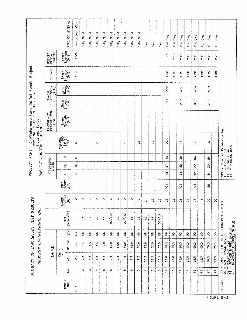
The result of all tests are tabulated or summarized on the boring logs presented on Figures
A-1 through A-4 in Appendix A. The summary of laboratory tests is also presented in a tabular form
on Figures B-1 through B-4 in Appendix B. The grain size distribution curves are presented on
Figures B-5 through B-11 in Appendix B.
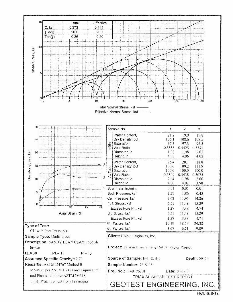
Multi-stage consolidated undrained (CU) triaxial compression tests (ASTM D 4767) were
conducted on three (3) soil samples. Three stages of consolidation (with pore pressure
measurements) were carried out on the samples following saturation of the samples and
consolidation to approximately 100%, 150% and 300% of estimated in situ overburden pressures.

Geotest Engineering, Inc. Report No. 1140196201
15 Windermere Lane Outfall Repair Project July 18, 2016
WBS No. M-000126-0073-3; Houston, Texas
8
The results are presented on Figures B-12 through B-14 in Appendix B. The CU triaxial
compression tests were shearing continuously after the peak strength to determine the residual
strength if possible.
Permeability test – falling head (ASTM D 5084) was performed on two (2) selected cohesive
soil samples and permeability test – constant head (ASTM D 2434) was performed on two (2)
selected granular soil samples. The results of falling head permeability test are presented on Figures
B-15.1 and B-15.2 and the results of constant head permeability test are presented on Figures B-15.3
and B-15.4 in Appendix B.
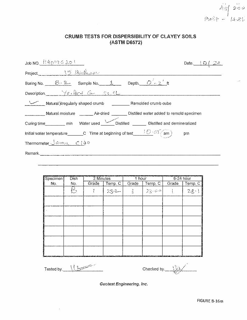
Two (2) Pinhole (ASTM D 4647) and three (3) Crumb tests (ASTM D 6572) were performed
on cohesive soil samples within the channel depth. Pinhole and crumb dispersion test results provide
a qualitative evaluation of the potential for soil dispersion in the presence of distilled water. The
results are presented on Figure B-16 in Appendix B. The Pinhole test and crumb test data sheets are
presented on Figures B-16a through B-16m. The Pinhole and Crumb test results indicated that the
tested soils are nondispersive.

Geotest Engineering, Inc. Report No. 1140196201
15 Windermere Lane Outfall Repair Project July 18, 2016
WBS No. M-000126-0073-3; Houston, Texas
9
4.0 SUBSURFACE CONDITIONS
4.1 Geology
The project area lies in the Beaumont Formation. The clays and sands of the Beaumont
Formation are over-consolidated as a result of desiccation from frequent rising and lowering of the
sea level and the groundwater table. Consequently, clays of this formation have moderate to high
shear strength and relatively low compressibility. The sands of the Beaumont Formation are
typically very fine and often silty. Further, there is occasional evidence in the Houston area of the
occurrence of cemented material (sandstone and siltstone) deposits within the Beaumont Formation.
4.2 General Fault Information
A review of information in the Geotest library, relating to known surface and subsurface
geologic faults in the general area of the project site, was undertaken. The available information
consisted of U.S. Geological and NASA maps, open file reports and information contained in our
files relating to geologic faults in the project area.
Based on the available information from U.S. Geological Survey (USGS) Maps and in-house
records relating to geologic faults for the project site, no documented faults exist in the project area.
A Phase I Geological Fault study is not required for this project.
4.3 Soils Stratigraphy
Based on the subsurface soils encountered in the boreholes, a boring log profile was
developed and is presented on Figure 3. To the right of each boring shown on the profile is the
overall classification of the soil contained within each stratum. The soil classification is based on
ASTM Standards.
The subsurface soils below existing ground surface as encountered in borings and as shown in
boring log profile are summarized below:

Geotest Engineering, Inc. Report No. 1140196201
15 Windermere Lane Outfall Repair Project July 18, 2016
WBS No. M-000126-0073-3; Houston, Texas
10
Boring No. Depth Below Existing
Ground Surface, feet
Elevation (ft) Soil Description
B-1 0-10 56.4 ~ 46.4 Stiff to hard gray and brown Sandy Lean Clay 10-28 46.4 ~ 28.4 Medium dense to dense gray, brown Silty Sand 28-37 28.4 ~ 19.4 Very dense brown Fine Sand w/silt 37-50 19.4 ~ 6.4 Very stiff to hard reddish brown Fat Clay 50-52 6.4 ~ 4.4 Stiff to very stiff reddish brown Lean Clay 52-78 4.4 ~ -21.6 Very stiff to hard reddish brown Fat Clay 78-93 -21.6 ~ -36.6 Dense to very dense gray Silty Sand 93-98.5 -36.6 ~ -42.1 Medium stiff to stiff gray Sandy Lean Clay 98.5-108.5 -42.1 ~ -52.1 Very dense brown Silty Sand 108.5-110 -52.1 ~ -53.6 Hard gray Lean Clay
B-2 0-12 60.8 ~ 48.8 Very stiff to hard gray Sandy Lean Clay 12-28 48.8 ~ 32.8 Medium dense to dense gray, yellow and brown
Silty Sand 28-40 32.8 ~ 20.8 Medium dense to very dense gray Fine Sand w/silt 40-44 20.8 ~ 16.8 Very dense reddish brown Silt 44-54 16.8 ~ 6.8 Very stiff to hard reddish brown Fat Clay 54-56 6.8 ~ 4.8 Very stiff reddish brown Lean Clay 56-88 4.8 ~ -27.2 Very stiff to hard gray, brown, reddish brown Fat
Clay 88-104 -27.2 ~ -43.2 Very dense gray Silty Sand 104-105 -43.2 ~ -44.2 Very stiff gray and brown Sandy Lean Clay 105-109 -44.2 ~ -48.2 Brown and gray Silty Sand w/gravel 109-110 -48.2 ~ -49.2 Hard gray and brown Lean Clay
B-3 0-2 53.6 ~ 51.6 Very stiff gray Sandy Lean Clay 2-23 51.6 ~ 30.6 Medium dense to very dense gray and yellow Silty
Sand 23-38 30.6 ~ 15.6 Very dense gray and brown Fine Sand w/silt 38-78.5 15.6 ~ -24.9 Stiff to hard reddish brown and gray Fat Clay 78.5-93 -24.9 ~ -39.4 Very dense gray and brown Silty Sand 93-100 -39.4 ~ -46.4 Very dense gray Fine Sand w/silt
B-4 0-4 40.7 ~ 36.7 Fill: soft to stiff gray lean clay 4-8.5 36.7 ~ 32.2 Fill: very loose to loose gray silty sand 8.5-12 32.2 ~ 28.7 Fill: medium stiff to very stiff dark gray, gray and
brown fat clay 12-16 28.7 ~ 24.7 Medium stiff to stiff dark gray Fat Clay 16-20 24.7 ~ 20.7 Very dense brown Fine Sand w/silt 20-80 20.7 ~ -39.3 Very stiff to hard reddish brown and gray Fat Clay
The Fat Clay is of high to very high plasticity with liquid limits ranging from 58 to 94 and
plasticity indices ranging from 35 to 61. The Lean Clay and Sandy Lean Clay are of low to high
plasticity with liquid limits ranging from 24 to 47 and plasticity indices ranging from 8 to 27. The
percent fines (percent passing No. 200 sieve) of Lean Clay and Fat Clay ranges from 88 to 100 percent.
The percent fines of Sandy Lean Clay ranges from 56 to 69 percent. The percent fines of Silty Sand

Geotest Engineering, Inc. Report No. 1140196201
15 Windermere Lane Outfall Repair Project July 18, 2016
WBS No. M-000126-0073-3; Houston, Texas
11
ranges from 14 to 28 percent, the percent fines of fine sand with silt ranges from 7 to 11 percent and
percent fines of Silt is about 98 percent. The lean clay encountered above 12 feet depth is
nondispersive. The hydraulic conductivity (permeability) of the tested samples of lean clay is about
4.72 x 10⁻⁶ cm/sec and fat clay is about 3.87 x 10⁻⁸ cm/sec. The hydraulic conductivity of the tested
samples of silty sand ranges from 9.50 x 10⁻³ cm/sec to 1.73 x 10⁻² cm/sec.
4.4 Water Levels
Groundwater was first encountered in borings at depths ranging from 16.0 to 28.0 feet during
drilling. The groundwater level, measured 10 to 15 minutes after water was first encountered, ranged
from 16.0 to 26.0 feet in these borings. The groundwater level measured 24 hours after drilling was
completed ranged from 15.8 to 25.8 feet in these borings. The water level encountered in borings is
summarized below.
Boring
No.
Groundwater During Drilling (ft)
Groundwater
Measured After 24
Hours of Drilling
Completion (ft)
First Encountered After 10 to 15 Mins Depth Elevation
Depth Elevation Depth Elevation
B-1 19.0 38.4 19.0 37.4 20.3 36.1
B-2 28.0 32.8 26.0 34.8 25.8 35.0
B-3 24.0 29.6 22.1 31.5 15.8 37.8
B-4 16.0 24.7 16.0 24.7 21.9 18.8
However, it should be noted that various environmental and man-made factors such as
amount of precipitation, nearby subsurface construction activities, and water level in Buffalo Bayou
can substantially influence the groundwater level.
4.5 Environmental Concerns
No environmental concerns were observed or noticed in any of the borings drilled for this
study.

Geotest Engineering, Inc. Report No. 1140196201
15 Windermere Lane Outfall Repair Project July 18, 2016
WBS No. M-000126-0073-3; Houston, Texas
12
5.0 ENGINEERING ANALYSES AND RECOMMENDATIONS
5.1 General
The project calls for the design and construction of the outfall repair at 15 Windermere Lane in
Houston, Texas. The project site is located behind the property of 15 Windermere Lane at south bank
of Buffalo Bayou. The proposed outfall replacement will consist of a new 32 linear feet of 102-inch
diameter corrugated metal pipe (CMP). The proposed CMP invert elevation will be El. 27 feet. The
channel (Buffalo Bayou) at outfall location will be improved with the construction of 4H:1V slope with
sheet pile retaining wall and riprap at toe and bayou bottom per Harris County Flood Control District
(HCFCD) requirements. The elevation at top of wall near CMP outfall area will be approximately El.
39.5 feet and El. 40.8 feet.
5.2 Open Excavation
Based on the information provided by United Engineers, Inc., it is understood that the 102-
inch diameter corrugated metal pipe (CMP) will be by open cut method of construction. The
following subsections provide information for the design and construction of the CMP and the
excavations required for the proposed open cut installation.
5.2.1 Geotechnical Parameters. Based on the soil conditions revealed by the borings B-1
through B-4, geotechnical parameters were developed for the design of open cut construction as part
of the outfall replacement with 102-inch diameter CMP. The design parameters for open cut
excavation are provided in Table 2. For design, the groundwater level should be assumed to exist at
the ground surface.
5.2.2 Excavation Stability. The open excavation may be shored or laid back to a stable slope
or supported by some other equivalent means used to provide safety for workers and adjacent
structures, if any. The excavating operations should be in accordance with OSHA Standards, OSHA
2207, Subpart P, latest revision and the City of Houston Standard Specification.

Geotest Engineering, Inc. Report No. 1140196201
15 Windermere Lane Outfall Repair Project July 18, 2016
WBS No. M-000126-0073-3; Houston, Texas
13
Excavation Shallower Than 5 Feet - Excavations that are less than 5-foot deep (critical
height) should be effectively protected when an indication of dangerous ground movement is
anticipated.
Excavations Deeper Than 5 Feet - Excavations that are deeper than 5 feet at this project site
should be shored, sheeted or braced or supported by some other equivalent means or
protection such that workers are not exposed to moving ground or cave-ins. The shoring
should be in accordance with the trench safety requirements as per OSHA Standards.
A soil retention system is recommended and essential for CMP construction of this project.
Whichever system is used should remain in place until backfilling is within 5 feet of the
ground surface. Based on the soil conditions and proposed excavation 30 feet deep for the
CMP, temporary sheet piles can be considered for soil retention.
Sheet piles may be driven or vibrated in place. We understand that due to the proximity of
the existing structures, driving/vibrating sheet piles will have some effect on existing
structures in the close proximate, if any and should be monitored closely.
The following items provide design criteria for excavation stability.
(i) OSHA Soil Type. Based on the soil conditions revealed by borings drilled for this
study and assumed groundwater level at surface, OSHA soil type “C” should be used
for the design of shoring for full proposed depth of open excavation. For shoring
deeper than 20 feet, an engineering evaluation is required.
(ii) Excavation Support Earth Pressure. Based on the subsurface conditions indicated by
our field investigation and laboratory testing results, excavation support earth
pressure diagrams were developed and are presented on Figures 4.1 and 4.2. These
pressure diagrams can be used for the design of temporary trench bracing. For a
trench box, a lateral earth pressure resulting from an equivalent fluid with a unit
weight of 90 pcf can be used. The effects of any surcharge loads at the ground
surface should be added to the computed lateral earth pressures. A surcharge load, q,

Geotest Engineering, Inc. Report No. 1140196201
15 Windermere Lane Outfall Repair Project July 18, 2016
WBS No. M-000126-0073-3; Houston, Texas
14
will typically result in a lateral load equal to 0.5 q. The above value of equivalent
fluid pressure is based on assumption that the groundwater level is near the ground
surface, since these conditions may exist after a heavy rain or flooding.
(iii) Bottom Stability. In braced cuts, if tight sheeting is terminated at the base of the cut,
the bottom of the excavation can become unstable. The parameters that govern the
stability of the excavation base are the soil shear strength and the differential
hydrostatic head between the groundwater level within the retained soils and the
groundwater level at the interior of the trench excavation. For cut in cohesive soils, if
applicable, the bottom stability can be evaluated as outlined on Figure 5. However
due to cohesionless soils (silty sand and fine sand) encountered between the depths of
10 and 40 feet in borings B-1 and B-2, between the depths of 2 and 38 feet in boring
B-3 and between the depths of 16 and 28 feet in boring B-4, dewatering or other
construction method such as cutoff wall as addressed in Section 6.2 will be required
to prevent bottom blow up.
5.3 Foundation for Outfall Structure
Based on the information provided to us, it is understood that the CMP outfall structure will
be supported on 36-inch diameter pipe piles filled with 3,000 psi concrete. Axial pile capacities for
36-inch diameter pipe pile were developed and are presented on Figure 6.1 (based on boring B-3)
and Figure 6.2 (based on boring B-4). The pile capacity curves (Figure 6.1 or 6.2) which results in a
deeper penetration should be used for the design. It should be noted that since borings were drilled
away from the outfall failure location and subsurface soils may be weaker at the location of the
failure next to Buffalo Bayou, it is recommended that the structural engineer should consider using
additional or extra safety factor in determining the depth or size of piles.
5.4 Sheet Pile Retaining Wall
Sheet pile retaining wall with whalers will be utilized to stabilize the bank of the bayou at the
location of outfall replacement. Based on the soil borings drilled for this project, design soil
parameters were developed for PY Wall analyses of sheet pile wall and are presented on Tables 3.1

Geotest Engineering, Inc. Report No. 1140196201
15 Windermere Lane Outfall Repair Project July 18, 2016
WBS No. M-000126-0073-3; Houston, Texas
15
and 3.2. These design soil parameters were provided to CSF Consulting LP for PY Wall analyses of
sheet pile wall. Based on the information provided to us, it is understood that the design tip of the
proposed PZ27 sheet pile retaining wall will be at about El. 0 feet near CMP outfall repair area. The
whalers (soldier piles) consist of 24-inch diameter pipe pile (about 40-foot long) and 36-inch
diameter pipe pile (about 55-foot long). It should be noted that since borings were drilled away from
the outfall failure and proposed sheet pile wall locations and subsurface soils may be weaker at the
location of the failure next to Buffalo Bayou, it is recommended that the structural engineer should
consider using additional or extra safety factor in determining the depth and size of sheet piles and
soldier piles.
5.5 Slope Stability Analyses
The project includes the channel (Buffalo Bayou) at outfall location (15 Windermere Lane) will
be improved with construction of 4(H):1(V) slope and sheet pile retaining wall with pipe whalers.
Slope stability analyses were performed for the improved slope at outfall location (15
Windermere Lane) with sheet pile wall based on the slope configurations (presented in Appendix C)
provided to us. For analyses, the bottom of sheet pile wall was assumed to be at El. 0 feet. The
analyses were performed using the Bishop Method of Analyses. Analyses conditions will consist of
End of Construction, Rapid Drawdown and Long Term cases. The required factors of safety per
HCFCD criteria for end of construction, rapid drawdown and long term condition are 1.3, 1.25 and
1.5, respectively.
5.5.1 Method of Analyses - Experience indicates that the failure of a slope occurs by
slippage along a surface of nearly circular cross section. Sufficiently accurate estimates of the
stability of such slopes can be made if the surface of sliding is assumed to be circular. Several
methods of slope stability analysis are available. The most commonly used method is known as the
Bishop Method. The calculation of the factor of safety against instability was performed using the
Bishop Method. Slope stability analyses were performed by using a computer program "Slide" with
the built-in critical section search algorithm for the improved slope with sheet pile wall at outfall
location (15 Windermere Lane) based on the configuration provided to us.

Geotest Engineering, Inc. Report No. 1140196201
15 Windermere Lane Outfall Repair Project July 18, 2016
WBS No. M-000126-0073-3; Houston, Texas
16
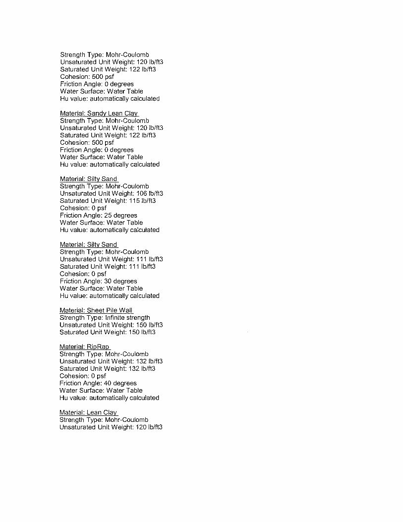
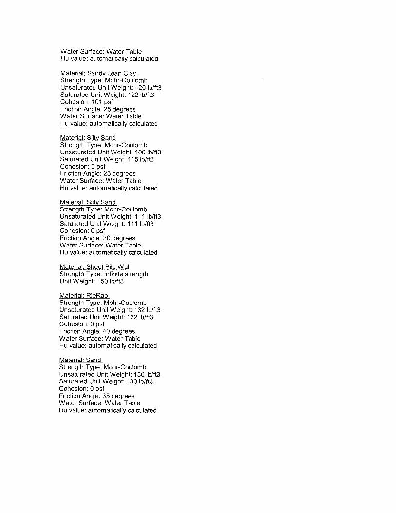
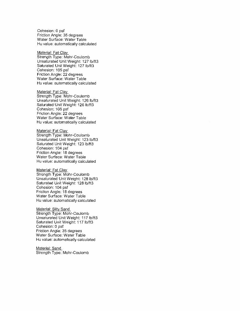
5.5.2 Soil Parameters and Water Level - To evaluate the potential stability of a slope, or to
assess the effectiveness of a slope, requires the physical properties of the geological material
involved to be measured. Shear strength characteristics of corresponding type of soil are discussed
below for each case. Slope stability analyses were performed for the End of Construction, Rapid
Drawdown and Long Term design cases for the proposed improved slope with sheetpile wall.
End of Construction: When a slope is excavated, altered stress conditions created pore
pressure changes within the slope. In cohesive soils, since no sufficient time to allow the
excess pore pressure to dissipate (drain) immediately or within a short period of time
after the completion of the slope excavation, thus undrained strength of the bank soil
should be considered for the end of construction case. For the analysis, 100-year flood
level was considered to be at El. 58 feet and water level within the channel was assumed
at normal water surface elevation (WSE) in the channel (El. 26 feet). For cohesive soils,
lower bound of unconsolidated undrained soil parameters were used for this case. For
granular/cohesionless soils, the angle of internal friction were based on the Standard
Penetration Test (SPT). The selected soil parameters are presented in Tables 4.1 and 4.2.
Rapid Drawdown: The rapid drawdown case models the condition where high
floodwater saturates and piezometerically “loads” the slope and then quickly recedes
leaving a large unbalanced piezometric head in the bank slope. This unbalanced force
increases the shear stresses in the soils behind the slope. For this analysis, 100-year flood
level within the slope was considered to be at El. 58 feet. The water level within the
slope was assumed to instantaneously drop from the 100-year flood level (El. 58 feet) to
the normal WSE in the channel (El. 26 feet).
Based on the fact that medium plasticity (sandy lean clay underlain by silty sand) was
encountered to channel bottom at the project site, effective stress cohesion (c') and
effective stress angle of internal friction ( ') were used for soils below the channel bottom
and residual values were used for soils above the channel bottom. The selected soil
parameters are presented in Tables 4.1 and 4.2.

Geotest Engineering, Inc. Report No. 1140196201
15 Windermere Lane Outfall Repair Project July 18, 2016
WBS No. M-000126-0073-3; Houston, Texas
17
Long Term: The long term design case represented steady state piezometric and stress
conditions. When a slope is excavated, altered stress conditions create pore pressure
changes within the slope and the undrained strength of the bank soils is mobilized. With
time, the soil pore pressures adjust to the imposed stress and piezometric conditions and
the bank soils rely on their available strength for long term stability. In the analysis, the
static water level within the channel embankment soils was assumed to be the
groundwater level El. 37.8 feet measured in the borings 24 hours after the completion of
drilling for section near boring B-3 and El. 37.8 feet to El. 26 feet (normal WSE) for
section near boring B-4. The water level in the channel was assumed at normal WSE (El.
26 feet). Effective stress cohesion (c') and effective stress angle of internal friction ( ')
were used for soils below the channel bottom and residual values were used for soils
above the channel bottom. The selected soil parameters are presented in Tables 4.1 and
4.2.
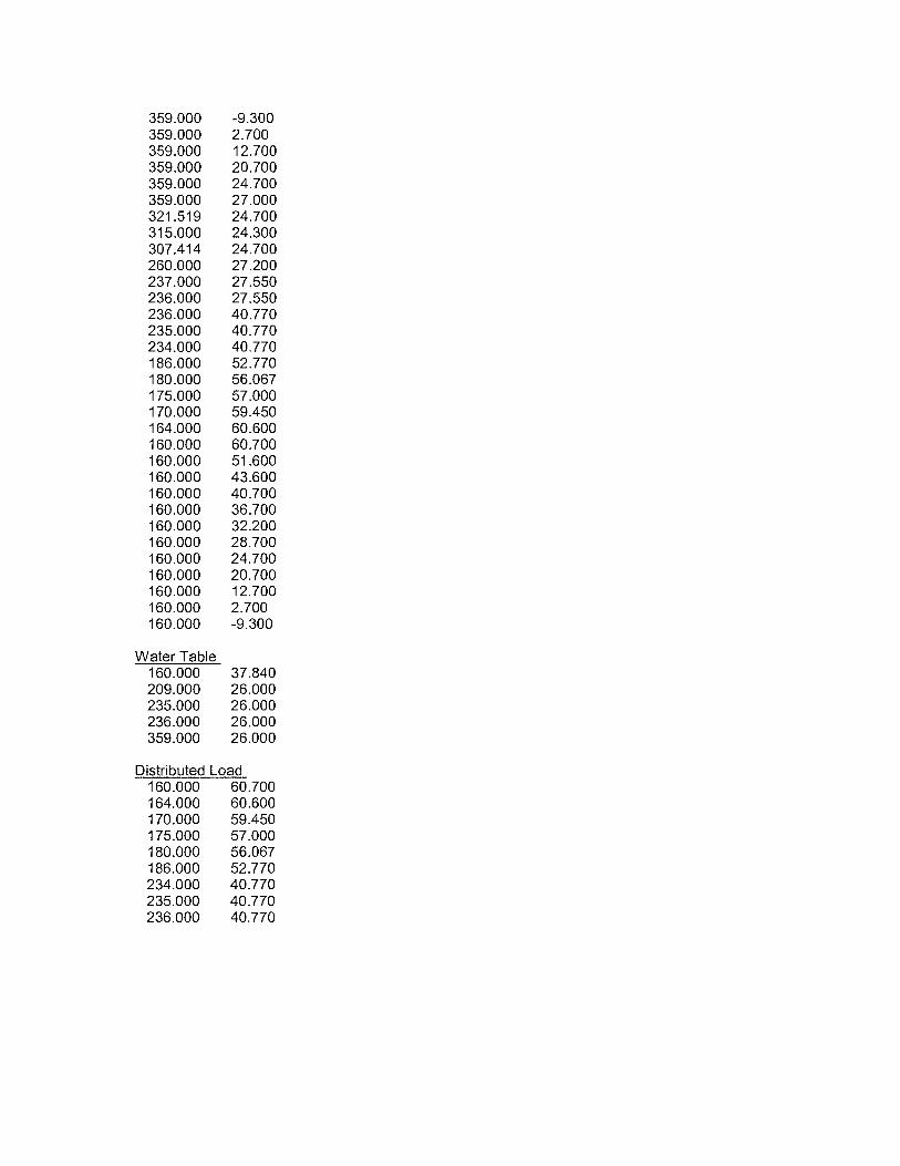
5.5.3 Loading Conditions - A surcharge load (construction or maintenance equipment) of
250 psf was assumed at the top of the bank and was considered for the short term (end of
construction) and long term conditions.
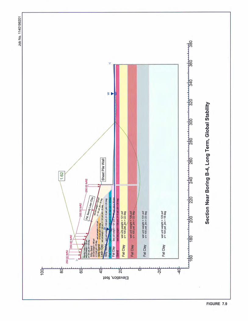
5.5.4 Factors of Safety – Slope stability analyses were performed for the proposed upper
4H:1V slope with sheet pile retaining wall. The information of the slide analysis is provided in
Appendix D. The results of slope stability analysis are graphically presented on Figures 7.1 through
7.12. The computed factors of safety are also tabulated below.
Boring No. Stability
Type
Factor of Safety Figure No.
EOC RD LT
B-3 Global 3.03 1.39 1.61 7.1 thru 7.3
Local 1.97 1.46 2.59 7.4 thru 7.6
B-4 Global 4.38 1.30 1.62 7.7 thru 7.9
Local 1.59 1.26 1.65 7.10 thru 7.12
As can be seen from the above table, the computed factors of safety for the 4H:1V slope with
sheet pile wall are meeting the HCFCD minimum required factor of safety of 1.30 for end of
construction, 1.25 for rapid drawdown and 1.50 for long term conditions.

Geotest Engineering, Inc. Report No. 1140196201
15 Windermere Lane Outfall Repair Project July 18, 2016
WBS No. M-000126-0073-3; Houston, Texas
18
However, it is recommended that the existing surface beyond the improved (4H:1V) slope
area be monitored and properly maintained and protected to prevent any surface erosion and
sloughing due to the presence of the silty sand which is prone to disturbance and erosion.
5.6 Excavated Soil for Structural Fill during Construction
Generally, the soils excavated in the upper 10 feet depth below existing ground during the
proposed construction will consist of predominantly of sandy lean clay. The sandy lean clay (upper
10 feet) is of medium plasticity with plasticity index varying from 8 to 26. Those cohesive soils that
have maximum liquid limit of 40 and plasticity indices less than 20 and more than 12 (after
laboratory verification at the time of construction) may be utilized as structural fill after removing all
roots and other deleterious material.
5.7 Slope Protection and Erosion Control
Any surficial silty sand and sand which are exposed to the surface and along the slope should
be properly protected from erosion. A riprap is proposed near the bottom of channel or may be
along the slope at where erosion is anticipated. A woven geosynthetic beneath the proposed riprap
would be required. The recommended Geotextile filter properties for the base soil (silty sand at site)
are given as follows:
Recommended Geotextile Properties
Geotextile Property Woven Monofilament Fabric Apparent Opening Size (AOS), mil (US sieve)
For Open Channel Flow: Between 4.2 mil (or US Sieve #140) and 7.3 mil (or US Sieve #80) For Wave Attack: Maximum 4.2 mil (or US Sieve #140)
Minimum hydraulic conductivity, ft/s
5.7 x 10⁻³
Minimum open area, percent 4.0 Minimum Grab Strength
315 lbs (Class 1) for Elongation < 50%, 200 lbs (Class 1) for Elongation > 50%
Minimum Sewn Seam Strength
270 lbs (Class 1) for Elongation < 50%, 180 lbs (Class 1) for Elongation > 50%
Minimum Tear Strength
110 lbs (Class 1)
Minimum Puncture Strength
110 lbs (Class 1)

Geotest Engineering, Inc. Report No. 1140196201
15 Windermere Lane Outfall Repair Project July 18, 2016
WBS No. M-000126-0073-3; Houston, Texas
19
6.0 CONSTRUCTION CONSIDERATIONS
6.1 Sheet Pile Wall and CMP Construction
Whenever practical, excavations should be performed during dry weather. All excavated
areas should be adequately protected from surface run-off water with appropriate measures to
prevent ponding of water in and around the excavation. Excavations should be properly sloped,
shored, braced, or protected in accordance with OSHA’s excavation safety standard, 29CFR Part
1926, Subpart P (Excavations and Trenches) Standards.
6.2 Groundwater Control
Based on the borings drilled, the majority of the excavation of CMP installation will be in
predominantly cohesionless soils (silty sand and sand) with groundwater level at El. 35.0 to El 37.8
feet. The approximate normal water level in the channel is at El. 26 feet. In view of the differential
water level in the bank (land side) and in the bayou, an effective groundwater control measures
should be implemented to maintain a dry working area. It is suggested that an approach consists of a
sheeting system with sufficient penetration to cutoff seepage of the groundwater from the land side
and a temporary cofferdam in the bayou with cutoff trench may be used to minimize the water
seeping into the working area. The minor seeping water can be controlled by a sump and pump.
However, actual methods and means of groundwater control and construction safety are the
contractor's responsibility.
6.3 Special Provisions
Since borings were drilled away from the outfall failure and proposed sheet pile wall
locations and subsurface soils may be weaker at the location of the failure next to Buffalo Bayou, it
is recommended that the design consultant should include a line item in construction document for
additional depth, penetration or length of sheet pile and soldier pile to account for any variation in
soil conditions that may be encountered at the outfall and sheet pile wall locations.

Geotest Engineering, Inc. Report No. 1140196201
15 Windermere Lane Outfall Repair Project July 18, 2016
WBS No. M-000126-0073-3; Houston, Texas
20
7.0 LIMITATIONS
The description of subsurface conditions and the design information contained in this report are
based on the soil borings made at the time of drilling at specific locations. However, some variation in
soil conditions may occur between soil borings. Should any subsurface conditions other than those
described in our boring logs be encountered, Geotest should be immediately notified so that further
investigation and supplemental recommendations can be provided. The depth of the groundwater level
may vary with changes in environmental conditions such as frequency and magnitude of rainfall. The
stratification lines on the log of borings represent the approximate boundaries between soil types,
however, the transition between soil types may be more gradual than depicted.
This report has been prepared for the exclusive use of City of Houston, Texas, and United
Engineers, Inc. for the Outfall Repair at 15 Windermere Lane in Houston, Texas. This report shall
not be reproduced without the written permission of Geotest Engineering, Inc., the City of Houston
or United Engineers, Inc.


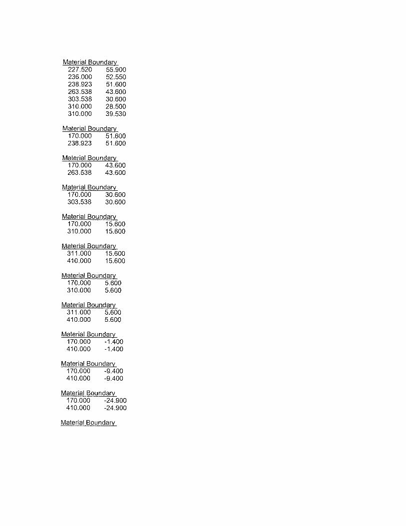
APPENDIX D
Slide Analysis Information