report on the workshop on neutrons for engineering … · workshop on neutrons for engineering...
TRANSCRIPT

Workshop on Neutrons for Engineering UNSW, Sept. 2002
ANSTO, NBIP Residual Stress Page 1 of 31
Report on theWorkshop on Neutrons for Engineering
and its conclusions regarding theResidual-Stress diffractometer at the
Australian Replacement ResearchReactor
School of Mechanical and Manufacturing EngineeringUniversity of New South Wales
Sydney
16th-17th September 2002

Workshop on Neutrons for Engineering UNSW, Sept. 2002
ANSTO, NBIP Residual Stress Page 2 of 31
Report on the Neutrons for Engineering Workshop, held at the School ofMechanical and Manufacturing Engineering at the University of New South Wales,
Sydney, 16th-17th September 2002
Prepared by the participants of the workshop
Edited: Oliver Kirstein, Tom Holden
1 INTRODUCTION 4
2 STRAIN AND TEXTURE MEASUREMENTS 6
2.1 Basic strain measurements 6
2.2 Texture 7
2.3 Recent developments 7
2.4 Complementarity with Synchrotron x-rays 8
3 SCIENCE AND ENGINEERING CASE 9
3.1 Origin of residual stresses 9
3.2 Engineering case 9
3.3 Science Case 11
4 INSTRUMENTAL CONSIDERATIONS 13
4.1 Introduction 13
Instrumental options 13
4.3 Constant wavelength instrument (CW) 14
4.4 Time-of-Flight (TOF) instrument 16
4.5 Time of experiments 18
4.6 Further remarks 20
5 ANCILLARY EQUIPMENT 21
Sample preparation facilities 21
5.2 Offline Mounting 21
5.3 Tensile testing equipment 21

Workshop on Neutrons for Engineering UNSW, Sept. 2002
ANSTO, NBIP Residual Stress Page 3 of 31
5.4 Other test rigs 21
5.5 Additional technical requirements 215.5.1 Overview and shared/different components 22
6 SOFTWARE 23
APPENDIX A ACCESS TO THE EQUIPMENT 24
APPENDIX B RESEARCH TRENDS AT OVERSEAS FACILITIES 25
APPENDIX C LIST OF PARTICIPANTS 26
APPENDIX D PROGRAM 28
REFERENCES 31

Workshop on Neutrons for Engineering UNSW, Sept. 2002
ANSTO, NBIP Residual Stress Page 4 of 31
1 INTRODUCTION
The workshop on “Neutrons for Engineering” was held on the 16th and 17th of September 2002 in
the School of Mechanical and Manufacturing Engineering at the University of New South Wales,
under the auspices of the University, ANSTO, AINSE and the Welding Technology Institute of
Australia. Forty participants attended, from 6 Australian Universities, New Zealand, Korea,
CSIRO, DSTO, the CRC for Welded Structures, 3 ANSTO Divisions, and 5 other leading
overseas laboratories. The principal focus was on stress scanning in a range of materials and
objects. All participants had the opportunity to give their vision for work in 2005 and beyond.
Figure 1: Attendees of ANSTO-UNSW workshop Neutrons for Engineering gather for groupphotograph during a short break in busy schedule.

Workshop on Neutrons for Engineering UNSW, Sept. 2002
ANSTO, NBIP Residual Stress Page 5 of 31
The purpose of the workshop was to:
� Inform the Australian research organizations and universities of the capabilities of an
engineering and materials science instrument.
� Promote the use of neutron diffraction to map and investigate strains/stresses in
materials and components for industrial applications and research
� Identify the future needs and opportunities in this area
� Present the options for a stress mapping diffractometer at the Replacement Research
Reactor and receive feedback on these options
� Identify the ancillary equipment and facilities required
There are a number of important benefits to Australia in the building of a first-class instrument
for materials science and engineering. There are many residual stress-related problems in a wide
variety of fields in Australia, such as the manufacturing industries, mining, oil and gas, rail
transport, defense and life extension. Stress scanning provides another tool for solving problems
to complement facilities at the major research institutes, CSIRO, AMIRA, DSTO, ANSTO and
the universities. It will create a regional pool of experts who may tap into the pool of expertise
internationally. The turn around time for tests for Australian customers will be reduced thus
avoiding having to go overseas to have the tests performed. From an educational perspective the
instrument will build expertise in Australia and will help to attract graduates into engineering.
A detailed list of the attendees and affiliations is in Appendix C.

Workshop on Neutrons for Engineering UNSW, Sept. 2002
ANSTO, NBIP Residual Stress Page 6 of 31
2 STRAIN AND TEXTURE MEASUREMENTS
2.1 Basic strain measurements
The spacing of the crystal lattice provides a natural gauge of the state of strain, and hence stress,locked within an engineering component. For this reason, diffraction measurements have beenperformed for at least seventy years to measure residual strains. These complement mechanical,but destructive, methods of measuring strains and have comparable accuracy. The basis of thetechnique is the use of Bragg’s Law
�=2dhkl sin�hkl (1)
to determine the lattice spacing of planes, dhkl, labelled by Miller indices (hkl), from thediffraction angle, 2�hkl, with a known wavelength �. The advantage of neutron diffraction overlaboratory x-ray sources is the high penetration through industrial materials. For example, 8% ofthe neutrons falling on 25mm of steel are transmitted, so that measurements of the lattice spacingmay be readily made all the way through this thickness of steel. The premier advantage ofneutrons is that lattice spacings, and hence strains, may be measured at depth in engineeringcomponents whereas laboratory x-rays are restricted to within a few microns of the surface.
When a stress of 100MPa is applied to a steel rod with Young’s modulus of 200GPa, the elasticstrain in the lattice is 5x10⁻⁴. If this strain is measured with neutrons of wavelength 2.9Å makinguse of the (110) reflection of body-centred cubic iron the angle of diffraction is about 90º and theshift in the peak is –0.06º. This gives the typical order of magnitude of shifts encountered inmeasuring strains in engineering components. Furthermore, if an accuracy of ±10MPa is needed,then the accuracy of the shift measurement has to be ±0.006º. This level of precision is easy toachieve with a careful set-up.
The size of the incident neutron beam falling on the sample is defined by absorbing slits (e.g.cadmium, B4C, BN etc.), see fig. 8. The width of the slits varies between 0.5 mm and 3 mm. Asimilar slit placed between the sample and the counter defines the size of the diffracted beam. Theintersection of these beams, referred to as the gauge or sampling volume, is fixed in space overthe centre of the instrument. The work-piece is placed on a computer-controlled XYZ translatoron the sample table and then it is easy to move any location in the specimen into the samplingvolume and measure the lattice spacing averaged over the sampling volume. The data have theform of a peak superposed on a uniform background. The peak position is obtained by fitting aGaussian on a flat or sloping background to the data. This gives a map of the lattice spacing as afunction of position in the sample for the sample direction which lies along the scattering vector.The elastic strain, �hkl, may be calculated from the lattice spacing with the aid of
�hkl =(dhkl-dhkl0)/ dhkl
0 (2)
where dhkl0 is an appropriate stress-free reference lattice spacing. We can describe the measured
strains in terms of the elements of a strain tensor, �ij, in a Cartesian axis system set up to define

Workshop on Neutrons for Engineering UNSW, Sept. 2002
ANSTO, NBIP Residual Stress Page 7 of 31
directions in the sample. Finally, the elements of the elastic stress tensor �ij may be calculatedfrom the elements of the elastic strain tensor �ij with the aid of Hooke’s law
�11=Ehkl{(1-�hkl)�11+�hkl�22+�hkl�33}/{(1+�hkl)( 1-2�hkl)} (3)and
�12=Ehkl�12/(1+�hkl) (4)
where Ehkl and �hkl are plane specific elastic constants relating the macroscopic stress to the strain,�ij, as measured with the (hkl) reflection.
A world-wide collaboration between about twenty laboratories has lead to a draft standard (ISOTTA 2001:30) [1,2] for measurement of residual strain and its interpretation in terms of residualstress in engineering components. The existence of a standard code of practice for carrying outthe measurements, covering both conventional diffraction and time-of-diffraction, is vital forindustrial and legal acceptance of the method.
2.2 Texture
The orientation of the grainsmaking up an engineeringcomponent is one factor thatgoverns the mechanical properties.As a rule, most manufacturingprocesses involve plasticdeformation. This has the effect ofaligning the crystal orientation ofthe grains in ways that depend onthe plastic deformation. In order tomeasure this distribution, or texture,the sample might be a small couponcut from a large component andmounted in an Euler cradle. Theintensities of several diffractionlines are measured systematically asa function of tilt and azimuth over acomplete hemisphere. The resultsare plotted as a contour map ofintensity known as a pole-figure,fig.2. Analysis of several pole-figures permits the calculation of the distribution in angle of thegrain orientations in the coupon. The measurements call for a low resolution, high intensity set-up.
2.3 Recent developments
The last five years have seen the construction of highly efficient purpose-built diffractometers formaterials science and engineering in several laboratories throughout the world. Typically theintensities of the beams falling on the sample have been enhanced by an order of magnitude. Forexample the new SMARTS spectrometer [4] at Los Alamos National Laboratory has eight timesthe intensity falling on the sample than the previously adapted NPD instrument. This translates
Figure 2: A pole figure is a stereographic projection, with aspecified orientation relative to the specimen, that shows thevariation of pole density with pole orientation for a selectedset of crystal planes. To determine the complete orientation ofa given sample, several pole figures are required for differenthkl planes. Shown here is the pole figure of an aluminumsheet [3].

Workshop on Neutrons for Engineering UNSW, Sept. 2002
ANSTO, NBIP Residual Stress Page 8 of 31
into the ability to improve the throughput or to tackle harder problems involving smaller gaugevolumes. New instruments are currently being constructed at the ISIS spallation source inEngland [5], at the ILL reactor in France [6], at the Munich reactor [7] and at the Swiss SINQsource [8]. A new instrument, VULCAN, is planned for the Spallation Neutron Source to be builtat Oak Ridge National Laboratory in the USA [9].
Residual Stress Instruments
SMARTS Los Alamos National Laboratory USAENGIN-X ISIS, Rutherford-Appleton-Laboratory GBD1A Institut Laue-Langevin FSTRESS-SPEC FRM-II Munich GPOLDI SINQ, Villigen SWVULCAN SNS, Oak Ridge National Laboratory USABT8 [10] NIST Center of Neutron Research USAL3 [11] Chalk River Laboratories CAN
Table 1: Overwiev of instruments especially designed for stress/strain measurements
2.4 Complementarity with Synchrotron x-rays
The development of instruments at the major synchrotron sources in the USA and Europe hasalso been rapid in the last five years. These make use of the copious x-ray flux at shortwavelengths (0.2-0.5Å) which permit measurement at depth. Although the diffraction angle issmall, the precision of d-spacing measurement is still high. The low diffraction angle howevergenerates a needle-shaped sampling volume with the long direction (of order mm) perpendicularto the scattering vector and the short direction (of order 0.05mm) parallel to the scattering vector.Microbeams even permit the examination of strains as a function of position within a grain,although the measurements are very time-consuming! There will be engineering problemsinvolving stress scanning which are better investigated with short wavelength x-rays because ofthe speed of collecting data and the small size of the gauge volume. On the other hand, there aremany cases where the path-lengths through the component are prohibitive or because of the highatomic number of the material. The consensus appears to be that the set-up for synchrotronmeasurement is more demanding than for neutrons and that inadequate sampling of grains whichfollows from the small sampling volume presents additional difficulties. Finally, the attenuationlengths for 0.2 Å x-rays are typically about 5 times smaller than for thermal neutrons althoughthis is offset to some degree by the much higher photon flux. It will be important to dovetailactivities in neutron strain scanning with synchrotron x-ray strain scanning. There will be teststhat are better carried out, ie. with higher accuracy and more insight or lower cost, with neutronsand vice versa.

Workshop on Neutrons for Engineering UNSW, Sept. 2002
ANSTO, NBIP Residual Stress Page 9 of 31
3 SCIENCE AND ENGINEERING CASE
3.1 Origin of residual stresses
Residual strains are locked into engineering components when their manufacture entails aninhomogeneous physical state across the component. For example a shrink-fit ring-and-plug, witha cooled plug inserted into a warm ring, generates a compressive stress in the plug and balancingtension in the ring. More generally, stresses occur when some part of the sample deformsplastically while an adjacent part deforms elastically. Examples include welding, where the weldmetal deforms plastically and the constraining parts deform elastically, or shot-peening where thesurface is compressed plastically and the interior elastically. These three examples give residualstress fields or type-1 stresses in the sample. The residual stress field must balance over thesample by Newton’s first law,
On the scale of the grain size, the response of individual grains is also inhomogeneous. Thiscomes from the intrinsic elastic anisotropy, as given by the single crystal elastic constants, andthe intrinsic plastic anisotropy, because only dislocations propagating in specific crystaldirections, in specific crystal planes, are allowed. Thus the deformation of a [111]-directed grainunder load differs from a [002]-directed grain. The strains that result from these differences indeformation are known as intergranular or type-2 stresses. Since the magnitudes of these grain-scale stresses depend on the allowed modes of plastic deformation, they provide a way ofstudying the modes of deformation by diffraction experiments which supplement directobservations of these dislocations by electron microscopy. However, the very conditions thatallow macroscopic stress fields to develop also permit intergranular strains to develop. Themeasured strain obtained from a particular set of Miller indices (hkl) has a contribution from bothtype-1 and type-2 strains. This is the major source of uncertainty in the interpretation of strain interms of stress.
3.2 Engineering case
Many Australian issues, in the manufacturing, oiland gas recovery and transportation, rail transportand life-extension will benefit from the results of,and the expertise developed around, strain scanningat the Replacement Research Reactor. Stress playsan acknowledged role in welding technologies.Stresses are the precursor to the distortionsoccurring upon welding. As well, tensile stressescan concentrate hydrogen near a weld and providesthe driving force for crack growth. The extent of thestress-field in a weld matches the spatial resolutioneasily available with strain scanning and providesinformation over the whole weld, near the surface aswell as at depth. Strain scanning provides adiagnostic tool to optimize post-weld heat treatmentto bring the stresses to acceptable levels since thesame sample can be repeatedly tested. It provides atool for improving the precision of the codes of
Figure 3: Head of a broken part of a railway(Figures taken from Railtrack ReportRT/PWG/001, February 2001 'Rollingcontact fatigue in rails, A guide to currentunderstanding and practice')
Workshop on Neutrons for Engineering UNSW, Sept. 2002
ANSTO, NBIP Residual Stress Page 10 of 31
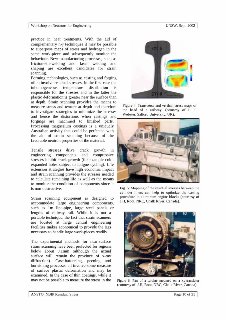
practice in heat treatments. With the aid ofcomplementary n-� techniques it may be possibleto superpose maps of stress and hydrogen in thesame work-piece and subsequently monitor thebehaviour. New manufacturing processes, such asfriction-stir-welding and laser welding andshaping are excellent candidates for strainscanning.Forming technologies, such as casting and forgingoften involve residual stresses. In the first case theinhomogeneous temperature distribution isresponsible for the stresses and in the latter theplastic deformation is greater near the surface thanat depth. Strain scanning provides the means tomeasure stress and texture at depth and thereforeto investigate strategies to minimize the stressesand hence the distortions when castings andforgings are machined to finished parts.Processing magnesium castings is a uniquelyAustralian activity that could be perfected withthe aid of strain scanning because of thefavorable neutron properties of the material.
Tensile stresses drive crack growth inengineering components and compressivestresses inhibit crack growth (for example cold-expanded holes subject to fatigue cycling). Lifeextension strategies have high economic impactand strain scanning provides the stresses neededto calculate remaining life as well as the meansto monitor the condition of components since itis non-destructive.
Strain scanning equipment is designed toaccommodate large engineering components,such as 1m line-pipe, large steel panels orlengths of railway rail. While it is not aportable technique, the fact that strain scannersare located at large central engineeringfacilities makes economical to provide the rigsnecessary to handle large work-pieces readily.
The experimental methods for near-surfacestrain scanning have been perfected for regionsbelow about 0.1mm (although the actualsurface will remain the province of x-raydiffraction). Case-hardening, peening andburnishing processes all involve some measureof surface plastic deformation and may beexamined. In the case of thin coatings, while itmay not be possible to measure the stress in the Figure 6: Part of a turbine mounted on a xy-translator
(courtesy of J.H, Root, NRC, Chalk River, Canada).
Figure 4: Transverse and vertical stress maps ofthe head of a railway. (courtesy of P. J.Webster, Salford University, UK).
Fig. 5: Mapping of the residual stresses between thecylinder liners can help to optimize the castingprocedure in aluminum engine blocks (courtesy ofJ.H, Root, NRC, Chalk River, Canada).

Workshop on Neutrons for Engineering UNSW, Sept. 2002
ANSTO, NBIP Residual Stress Page 11 of 31
coating because of the small quantity of material, the balancing effects in the material under thecoating, which are hard to investigate by other methods, are amenable to strain scanning.
The increased use of finite-element modeling in many industrial processes, such as casting,squeeze-casting, forging and welding is well recognized. These replace older rule-of-thumbmethods and are more reliable, in principle, and more economical. However, unwarrantedassumptions are often needed to do the calculations and residual stresses are quite difficult tocalculate in any case. One of the premier uses of strain-scanning in the future will be to test finiteelement codes. It is interesting that the spatial mesh of the finite models often matches the spatialresolution available in the neutron tests.
3.3 Science Case
The materials science case is based on the ability to measure the strain response to an appliedstimulus, stress or temperature for example, on the application to new materials or to materials innew subject areas. There is current interest in the response of anisotropic materials such as Be, Ti,Zr and Mg. Basal, prism and pyramidal slip systems all play a role because of the limited numberof degrees of freedom permitted to any one slip system. In addition, depending on the texture,deformation by twinning may occur. The method, used in conjunction with material models suchas the elasto-plastic self-consistent model [12], permits an identification of the strength of the slipmodes. Ultimately, this research is aimed at providing more accurate constitutive models ofmaterial response, including texture and stress, which will, in turn, be used within a finite elementmodel of complete structures. The method may be extended to include the mechanical behaviorof multiphase materials such as ceramics containing a toughening phase, and shape-memoryalloys. To date most work has been done at room temperature and it is natural to expect that thefuture will include the study of industrial materials at high and low temperatures.
One topic that holds promise but has not been investigated, is the role of intergranular stress andtexture in stress-corrosion cracking. Since specific grain orientations abutting on a sample surfacehave larger residual stresses than average, it is natural to ask whether these are more susceptibleto corrosion. There may be no net stress on a sample, but yet considerable tensile stresses exist inone set of grains balanced by compression in another set of grains. A thorough study mightindicate new approaches based on the stress and texture of the grains to minimise stress corrosioncracking.
The study of the load sharing between various phases in rock sample is an example of anapplication to a new field. It is well suited to the technique since each phase gives a distinctpattern of response. This could have an impact on the structural use of rocks as well as in thefundamental understanding of their mechanical behaviour. Since the method may be applied toany system with sharp diffraction lines, there are applications to material as diverse as cement andbone.
With the advent of more intense beams there will be increased emphasis on the dynamicbehaviour of components, such as the stress produced in a meshing gear train. Experiments willfollow the relaxation of stresses with time in a component subjected to an increased temperatureor the change in strain or peak width with time following the application of an applied load.Measurements of the reduction of compressive stresses in fatigue cycling could easily be carriedout in situ. It is not inconceivable that a small welding rig could be mounted on the equipment toallow measurement of the stress at temperature in the weld.

Workshop on Neutrons for Engineering UNSW, Sept. 2002
ANSTO, NBIP Residual Stress Page 12 of 31
There is an acknowledged need to attract more students into the field of engineering. One couldenvisage an important role here in the provision of research training at the graduate level in bothstrain scanning of components of industrial interest as well as the underlying materials sciencewith this instrument. The staff manning the engineering instrument will, in due course, providethe scientific expertise to provide advice to academic users on the best way to set up and carry outthe tests and to interpret the results. For industrial users, operating on a contract research basis,staff will design and carry out the tests and provide a high quality report for the customer.Essentially the staff will become a centre of excellence in training and knowledge of the subject.
Workshop on Neutrons for Engineering UNSW, Sept. 2002
ANSTO, NBIP Residual Stress Page 13 of 31
4 Instrumental considerations
4.1 Introduction
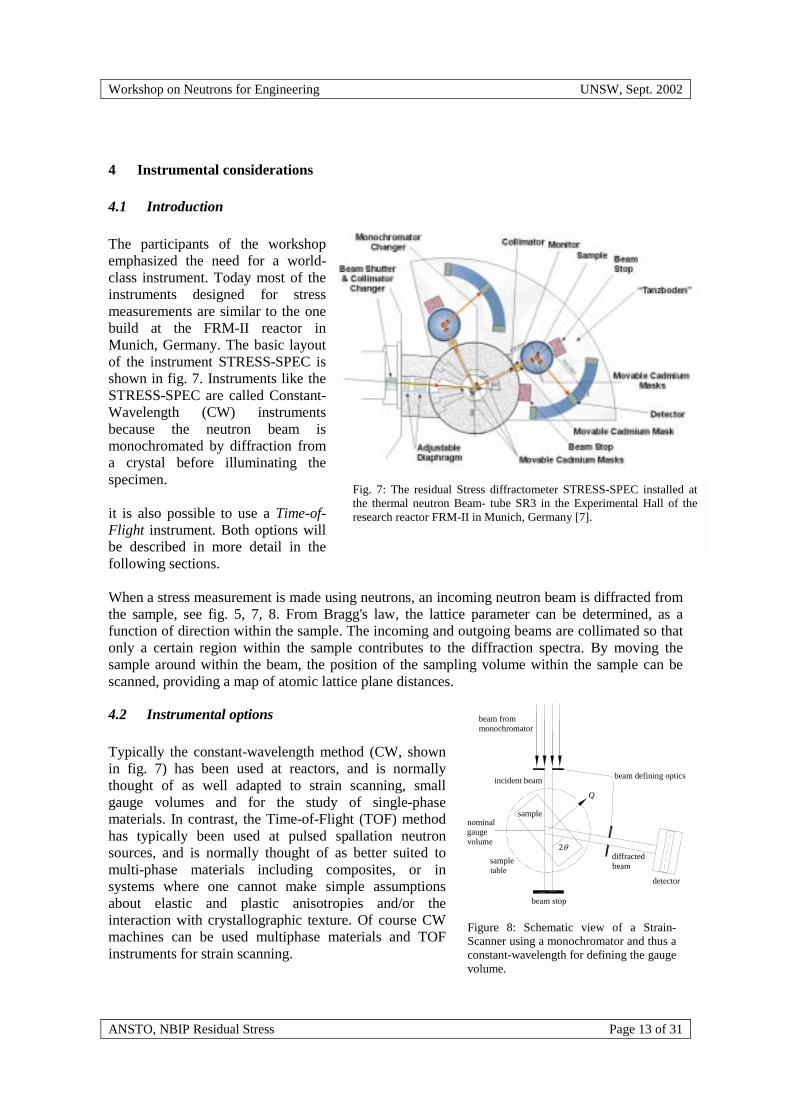
The participants of the workshopemphasized the need for a world-class instrument. Today most of theinstruments designed for stressmeasurements are similar to the onebuild at the FRM-II reactor inMunich, Germany. The basic layoutof the instrument STRESS-SPEC isshown in fig. 7. Instruments like theSTRESS-SPEC are called Constant-Wavelength (CW) instrumentsbecause the neutron beam ismonochromated by diffraction froma crystal before illuminating thespecimen.
it is also possible to use a Time-of-Flight instrument. Both options willbe described in more detail in thefollowing sections.
When a stress measurement is made using neutrons, an incoming neutron beam is diffracted fromthe sample, see fig. 5, 7, 8. From Bragg's law, the lattice parameter can be determined, as afunction of direction within the sample. The incoming and outgoing beams are collimated so thatonly a certain region within the sample contributes to the diffraction spectra. By moving thesample around within the beam, the position of the sampling volume within the sample can bescanned, providing a map of atomic lattice plane distances.
4.2 Instrumental options
Typically the constant-wavelength method (CW, shownin fig. 7) has been used at reactors, and is normallythought of as well adapted to strain scanning, smallgauge volumes and for the study of single-phasematerials. In contrast, the Time-of-Flight (TOF) methodhas typically been used at pulsed spallation neutronsources, and is normally thought of as better suited tomulti-phase materials including composites, or insystems where one cannot make simple assumptionsabout elastic and plastic anisotropies and/or theinteraction with crystallographic texture. Of course CWmachines can be used multiphase materials and TOFinstruments for strain scanning.
Fig. 7: The residual Stress diffractometer STRESS-SPEC installed atthe thermal neutron Beam- tube SR3 in the Experimental Hall of theresearch reactor FRM-II in Munich, Germany [7].
2�
Q
beam defining optics
detector
diffracted beam
incident beam
beam stop
sample
sample table
nominal gauge volume
beam from monochromator
Figure 8: Schematic view of a Strain-Scanner using a monochromator and thus aconstant-wavelength for defining the gaugevolume.

Workshop on Neutrons for Engineering UNSW, Sept. 2002
ANSTO, NBIP Residual Stress Page 14 of 31
Both options, ie. CW and TOF instruments, are considered in the following sections for theReplacement Research Reactor diffractometer.
The scanning of strain is based on the Bragg’s law, eqn. (1). Typically strain scanners like theD1A at the ILL are based on the differential form of eqn. (1). The differential Bragg equation ata constant wavelength � gives the lattice strain
� = �d/d = -��/tan� (5a)
which corresponds to a shift �� of an observed Bragg peak.
Contrary to this the TOF option gives the lattice strain
� = �t/t (5a)
at a constant scattering angle 2�, as a shift of the arrival time of the neutrons in the time sensitivedetector with respect to a stress-free sample. This is possible since the wavelength and thevelocity of the neutrons are linked according to de Broglie’s relation in a simple way as
vNeut ��Neutron = 3956 m�Å/s (6)
In both cases the shifts of the Bragg peaks are correlated to the type 1 and type 2 strains andhence to stress in the material.
The widths of the peaks are related to the plastic strain and the intensities to the texture of thesample under investigation.
4.3 Constant wavelength instrument (CW)
Typically the strains observed in materials are of the order of � = 10-3. According to eqn. (5) thisrequires a �� / tan� resolution of 10-3. Since the gauge volume is well defined as a cube in shapethe angle 2� is 90o and the contribution term to the resolution is given by �� only. A possiblegeometrical arrangement for a CW instrument is shown in fig. 9 where the diffraction angle at 2�being is 90o.
The requirements on the strain vary between 10-4 and 10-3.Typically the standard resolution which an be obtained byusing the neutron strain scanning technique is � = 2�10-3 andthus is ��. The full width at half maximum at 2� can becalculated according to Cagliotti et al. [13,14,15,16] and isgiven by
��2 = U�tan2�+V�tan2�+W (2) with
� U=(2.5�12+2�2)/tan2�M
� V=-(2.5�12+4�2)/tan�M
� W=0.5�12+2�2+3
2Figure 9: Constant wavelengthinstrument using two collimators todefine the resolution and the gaugevolume. The guide defines �1, theradial collimators �2 and �3 [17].

Workshop on Neutrons for Engineering UNSW, Sept. 2002
ANSTO, NBIP Residual Stress Page 15 of 31
Here 2� and 2�M are the diffraction angles for the sample and the monochromator. For 2�=90o itfollows that the resolution �� depends on the used collimations i and the mosaicity of themonochromator used only. A typical setup using a collimator system is shown in fig. 9.Here 1is given by the characteristics of the neutron guide (it can also be defined by a standardcollimator), 2 by beam collimator between the monochromator and the sample and 3 by thecollimator between the sample and the detector system. Using eqn. (2) a resolution of �� = 2.5 �10-3 = � can be obtained by using a combination of i = = 0.1o. The resolution can be chosen byusing different collimations. Some possible values are given in table 1 assuming a crystalmosaicity of =0.1o.
1 in o 2 in o 3 in o �d/d � 10-3
0.1 0.1 0.1 2.50.1 0.1 0.2 3.90.1 0.1 0.4 7.20.2 0.4 0.1 3.90.2 0.4 0.2 4.90.2 0.4 0.4 7.8
In order to calculate for the diffractometer of the Replacement Research Reactor the neutronintensity to a first approximation at the sample position it is assumed that the diffractometer isplaced at the thermal guide TG3 inside the neutron guide. This neutron guide is curved with aradius of curvature of 4.5 km. The top, base and outer side of the guide is coated withsupermirrors according to m = 3 whereas the inner side is covered with m = 2.5. It is furtherassumed that we have a flat wavelength distribution1, which might be justified since the incomingwavelength band of neutrons is very narrow and that the vertical beam divergence contributes tothe intensity only.
Typically the incoming neutron wavelength is 1 Å. The m = 3 coating corresponds to a beamdivergence given by the critical angle of reflection �c = 3 * 0.099 * 1 = 0.297o (HWHM).Thinking of horizontal acceptance the first collimator (assuming that a classical collimator isused, contrary to fig. 9) accepts f(1) = 1 / (2*�c) = 0.1o / (0.594o) = 0.17 of the neutronintensity. The neutrons are then reflected by the monochromator, which is typically a germaniumor gopper crystal with reflectivities of R � 0.3 for thermal neutrons. From all of the neutrons thathit the monochromator, after the reflection some 30 %, are transported towards the sampleposition with an outgoing divergence of 2 = 2*1+ = 0.3o. The second collimator 2 has anacceptance of 0.1o meaning that 33% of the neutrons are transported onto the sample, f(2) =0.33. At the sample the neutrons are scattered into 4� and after passing the third collimator f(3)detector, covering a solid angle ��, counts the neutrons. Thus it is possible to estimate thenumber of neutrons arriving at the detector:
�Det = �0 � f(1) � R � f(2) � � �� / (4�) � f(3) (8)
�Det = 2.9 � 10-5 � �� / (4�) � f(3) (9) 1 For a detailed Monte Carlo simulation the “real” thermal Maxwellian distribution of the neutron velocitieswill be taken into account.
Table 2: Possible combinations of collimations and the resulting resolutions of the latticespacings / strains (FWHM).

Workshop on Neutrons for Engineering UNSW, Sept. 2002
ANSTO, NBIP Residual Stress Page 16 of 31
with the initial intensity �0 provided by the guide TG3. It can be seen that the intensity �0 isproportional to the collimations and the mosaicity of the monochromator
�0 � 1 � 2 � � 3 (10)
4.4 Time-of-Flight (TOF) instrument
Contrary to the constant wavelength instrument where the strain is measured by examining theshift in the angle of the Bragg peaks with respect to a stress free sample, for a TOF the strain isdetermined by the relative shift in the arrival time of the neutrons when they hit the (timesensitive) detector. In this case the resolution (and thus the strain resolution �) is given by2
�d / d = ((�L/ L)2 +(�t / t)2 + (�� / tan�)2 )1/2 (11)
where �t / t is the flight time uncertainty of the neutrons and �� / tan� the angular uncertainty
given by the properties of the neutron guide and detector system used.. (�L/ L) describes theuncertainty of the length of the path again determined mainly by the properties of the neutronguide. To get a�d / d = 2.5 � 10-3 , which was the design criterion for the CW instrument, both contributions,angular and time of flight, have to be 1.76 � 10-3. Since the source is continuous, thestraightforward way of designing a TOF instrument is to operate with choppers which simulate apulsed source, thereby giving the possibility of assigning neutrons a time when they pass thechopper. The term (�t / t) is then given by the duration of the pulse �t and the length of the flight-path L which is given by L = vNeutron � tNeutron. It is easy to see that the (�t / t) term may be adjustedby the duration of the chopper pulse and / or the length of the flight-path L. For the ReplacementResearch Reactor a combination of �t = 10 �sec and L = 20 – 25 m seems to be feasible.
2 Typically the spatial contribution �L/L is in the order of 10-4
“Stress” detectorsystem at +90o.
Figure 10: Possible setup of a Time-Of-Flight diffractometer. It should be emphasized that this specificlayout is optimized for high-resolution and not for Residual Stress measurements. Due to this anadditional detector system covers high scattering angles [17].
“Stress” detectorsystem at -90o.
Workshop on Neutrons for Engineering UNSW, Sept. 2002
ANSTO, NBIP Residual Stress Page 17 of 31
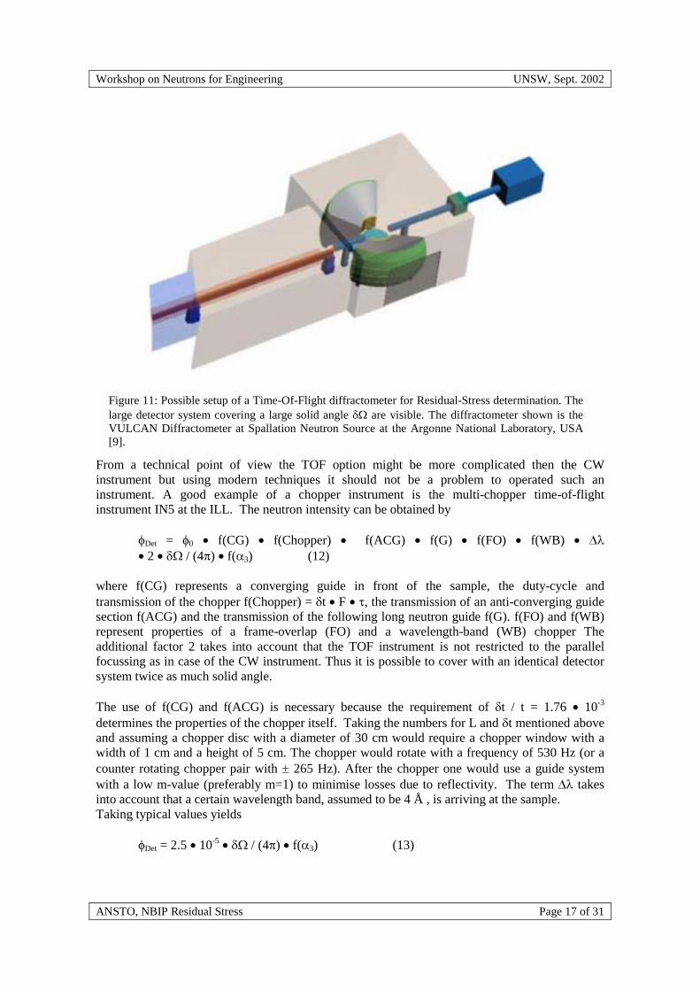
From a technical point of view the TOF option might be more complicated then the CWinstrument but using modern techniques it should not be a problem to operated such aninstrument. A good example of a chopper instrument is the multi-chopper time-of-flightinstrument IN5 at the ILL. The neutron intensity can be obtained by
�Det = �0 � f(CG) � f(Chopper) � f(ACG) � f(G) � f(FO) � f(WB) � ��� 2 � �� / (4�) � f(3) (12)
where f(CG) represents a converging guide in front of the sample, the duty-cycle andtransmission of the chopper f(Chopper) = �t � F � �, the transmission of an anti-converging guidesection f(ACG) and the transmission of the following long neutron guide f(G). f(FO) and f(WB)represent properties of a frame-overlap (FO) and a wavelength-band (WB) chopper Theadditional factor 2 takes into account that the TOF instrument is not restricted to the parallelfocussing as in case of the CW instrument. Thus it is possible to cover with an identical detectorsystem twice as much solid angle.
The use of f(CG) and f(ACG) is necessary because the requirement of �t / t = 1.76 � 10-3
determines the properties of the chopper itself. Taking the numbers for L and �t mentioned aboveand assuming a chopper disc with a diameter of 30 cm would require a chopper window with awidth of 1 cm and a height of 5 cm. The chopper would rotate with a frequency of 530 Hz (or acounter rotating chopper pair with � 265 Hz). After the chopper one would use a guide systemwith a low m-value (preferably m=1) to minimise losses due to reflectivity. The term �� takesinto account that a certain wavelength band, assumed to be 4 Š, is arriving at the sample.Taking typical values yields
�Det = 2.5 � 10-5 � �� / (4�) � f(3) (13)
Figure 11: Possible setup of a Time-Of-Flight diffractometer for Residual-Stress determination. Thelarge detector system covering a large solid angle �� are visible. The diffractometer shown is theVULCAN Diffractometer at Spallation Neutron Source at the Argonne National Laboratory, USA[9].

Workshop on Neutrons for Engineering UNSW, Sept. 2002
ANSTO, NBIP Residual Stress Page 18 of 31
which is comparable to the values derived in case of the CW instrument, see eqn. (9). Since weare primarily interested in the relative performance of both instruments it is assumed that thecollimator-detector-system after the sample is the same for both setups.
4.5 Time of experiments
The relative times for an experiment using either a TOF or a CW instrument can be derived bythe following formulas:
Ihkl � �Det � �hkl3 � mhkl � |Fhkl|2 [Ihkl ]=[n/sec] (CW) (14a)
and
Ihkl � �Det � �hkl4 � mhkl � |Fhkl|2 [Ihkl ]=[n/sec] (TOF) (14b)
Where Ihkl is the intensity of the reflection in n/sec, �hkl the “wavelength” of the reflectionaccording to Bragg’s law, mhkl the multiplicity and Fhkl the structure factor of the reflection.
An alloy which might be useful to check the properties of both different instrument types ishypothetical -�-Fe. Here -Fe represents a bcc-structure with a lattice constant of a0 = 2.87 Åwhereas �-Fe represents a fcc-structure with a0 = 3.62 Å.
�-Fe �-Fehkl h2+k2+l2 mhkl 2d in Å t20m in
�secmhkl 2d in Å t20m in
�sec100 1110 2 X 24 4.058 14507111 3 X 8 4.180 14943200 4 X 6 2.870 10260 X 6 3.620 12941210 5211 6 X 48 2.344 8379220 8 X 24 2.030 7257 X 24 2.560 9152221/300
9
310 10 X 24 1.816 6492311 11 X 38 2.182 7800222 12 X 8 1.656 5920 X 8 2.090 7471

Workshop on Neutrons for Engineering UNSW, Sept. 2002
ANSTO, NBIP Residual Stress Page 19 of 31
320 13321 14 X 48 1.534 5484400 16 X 6 1.436 5133 X 6 1.810 6470410/322
17
411/330
18 X 48/24 1.352 4833
331 19 X 48 1.706 6099mhkl=48, mhk0=24, mhhh=8, mh00=6
Table 3: Possible hkl-values for a hypothetical alloy consisting of �- and �-Fe.
Here a flight-path of 20 m is assumed for the TOF instrument. By using2 d �2 / 2 = � the TOF flight measurement is determined by the reflection with the lowestmultiplicity (400 reflection of -Fe) whereas the CW needs a sequential measurement of the boldfaced reflections given in the table above.
This example shows that the TOF flight experiment on -�-Fe alloy would allow to measure eightreflexes simultaneously in 0.16 time-units (TUTOF). The CW experiment would need eightmeasurements and require 0.45 TUCW.
Thus the gain can be estimated by calculating
G = TUCW / TUTOF = {�1/ Ihkl (CW) }/ {1/ Ihkl (TOF)} = 2.8 (15)
neglecting dead-time effects due to re-adjusting the CW instrument as well as assuming that bothinstrument have the same detector setup.
One remark should be made with respect to table 3: the flight-times in bold are observable with aTOF instrument without having a frame-overlap (FO). Frame overlap occurs if a fast neutronshits the detector at the same time as the slowest neutrons from the previous pulse. Since bothneutrons would be counted in the same time-bin it would be impossible to distinguish them.
The FO can be seen in the following way: The chopper rotates with a frequency of 530 Hzmeaning one rotation needs 1 / 530 Hz = 1887 �sec. In the hypothetical example the fastestneutron corresponds to the 411 / 330 reflection of the -Fe and is detected after 4833 �sec. Aneutron from the subsequent pulse corresponding to this reflection will be detected after 1887�sec + 4833 �sec = 6720 �sec. Thus it might happen that the 220 (211) is identified as the 321(310) reflection. This effect does not occur in case of the CW instrument where the peaks areobserved individually.

Workshop on Neutrons for Engineering UNSW, Sept. 2002
ANSTO, NBIP Residual Stress Page 20 of 31
4.6 Further remarks
It should be emphasised at this point that the above mentioned arguments and conclusions are justfor illustrating the basic properties of both instruments and ment to start a discussion of the needsof the user community. During the workshop it was not clear if either the CW or TOF instrumentis the one of choice. It was desired to evaluate both possible options in more detail by aninstrument-specific Monte-Carlo simulation taking into account all the relevant distributions withrespect to the source, guides, monochromator, choppers etc. This evaluation should be the basison which either the one or the other option should realized at the Replacement Research Reactor.

Workshop on Neutrons for Engineering UNSW, Sept. 2002
ANSTO, NBIP Residual Stress Page 21 of 31
5 ANCILLARY EQUIPMENT
5.1 Sample preparation facilitiesThe tools for mounting samples on the standard top-plate ofthe sample table should be designed so that the position ofany point on the sample is guaranteed mechanically to afraction of a mm. It would be useful to have a “Meccano”set of mounting tools to handle odd-shaped samples. TheVAMAS [10] standard breadboard is useful for mountingsmall regularly shaped samples such as plates and cylindersand is likely to be accurate to �0.1mm.
5.2 Offline MountingOffline mounting can improve the throughput of theinstrument by preparing the next sample to be tested on astandard mount. It could be part of an off-line physicalsimulator to test the scan set for collisions. On the otherhand a virtual simulator, which would use scanneddimensions of the specimen, could achieve the same goals.A coordinate measuring machine for moderate sizedsamples (50x50x50mm3) exists at ANSTO but it appearsthat it cannot be modified to enable appropriatemeasurements. A dedicated local crane (1500kg) is desirablefor mounting or sometimes supporting heavy samples or themechanical testing equipment.
5.3 Tensile testing equipmentA mechanical test-rig is an integral part of the instrument.This should be designed so that it mounts on the top plate ofthe sample table and to provide tension (and compression)on a variety of standard tensile test sample shapes. The stateof the art is presently 48 kN. It should be also possible to apply the load in a variety of gaseousatmospheres at high (1500�K) and low (4.2�K) temperatures. It should be possible to applydynamic and cyclic as well as static loading. It is expected that, as is common at other facilities, asuite of cryostats and furnaces would be available to mount interchangeably on any instrument atthe reactor.
5.4 Other test rigsA smaller test-rig should be available which may be oriented in any direction with respect to theincident and diffracted beam. An on-line thermal or fatigue cycling test-rig would complementoff-line fatigue cycling equipment that already exists within ANSTO.
5.5 Additional technical requirements
Additional services required for an experiment are: cooling water, air, electricity, ethernetconnection as well as an office dedicated to the instrument.
25
10
6
5.9
Fig. 12: VAMAS TWA20 StandardBreadboard Base-plate DesignISO/TTA3: 2001.
25
25
70
2525
305
155
15
70
47
10
Fig. 13: ‘Salford’ holder for platesamples ISO/TTA3: 2001.The Simpleholder takes plate samples with 6 mmdiameter straight holes, on a 25 mmsquare matrix matching the base-plate.

Workshop on Neutrons for Engineering UNSW, Sept. 2002
ANSTO, NBIP Residual Stress Page 22 of 31
5.5.1 Overview and shared/different components
The following table shows the sample environment, which was identified to be necessary duringthe workshop.
Device Specification Required / Desiredxyz translation table (precision
� 50 �m)500 kg load required
xy table(precision � 50 �m)
1000 – 1500 kg load required
Eulerian cradle Small specimens requiredFurnaceStandardMirror
Split furnace
1000o C1700o C
requireddesireddesired
Bending device requiredTesting machine 20 tonnes requiredHydrostatic press 0 - 10 GPa desired
Table 4: Overview of the sample environment
Fig. 14: Common and unique components of a CW and a TOF instrument.

Workshop on Neutrons for Engineering UNSW, Sept. 2002
ANSTO, NBIP Residual Stress Page 23 of 31
6 Software
An efficient experiment is not governed by the data acquisition alone. A user-instrument shouldprovide the possibility of on-line data analysis as well a (nearly) on-line presentation of stress /strain versus position with the uncertainties also indicated.
This analysis includes e.g.
� Linear graphs� 2D maps� 3D maps
Additionally, the peak parameters should be monitored continuously to check the quality of theexperimental data and it is desirable to output results in a format that makes it suitable as an inputfor Finite-Element-Analysis (FEA) software.
Improvements in the time/safety required for an experiment might be possible if the instrumentsoftware is able to provide an interface with a CAD/FEA application. This would offer thepossibility to transfer the sample into a virtual instrument for defining and checking the individualscans with respect to e.g. geometrical restrictions due to the slit-system beforehand.
A special effort should be made to consider the needs of the likely user-community: Thiscommunity, mainly engineers, has needs and expectations compared to the typical community ofphysicists typically associated with neutron scattering instruments and meeting these will requirestrong communications.
Figure 15: Scans and maps of longitudinal (X), transverse (Y) and normal (Z) residualstresses in a ferretic steel weld (courtesy of P.J. Webster, Salford University, UK).
longitudinal (X)
transverse (Y)
Workshop on Neutrons for Engineering UNSW, Sept. 2002
ANSTO, NBIP Residual Stress Page 24 of 31
APPENDIX A Access to the equipmentTwo modes of access to the instrument were envisaged. The first is the peer-reviewed proposalroute which will be common to the whole scientific program on instruments at the reactor. Thesecond is the contract research route whereby the customer defines the set of tests, pays for theuse of the facility and the services of the staff carrying out the test and preparing a proprietaryreport, and owns the intellectual property. In some cases sharing of the intellectual property andfee sharing may be appropriate.
The peer review process must be carried out sufficiently frequently so as not to discouragepotential users. For example, one year between requests for proposals is an appreciable fraction ofthe time to finish a Ph.D. Serious consideration should be given to funding travel andaccommodation for all peer reviewed projects.
Industry requires a rapid turn around for a test. Otherwise the project is likely to be takenelsewhere, since the business is global - or simply dropped. In general, experience at otherfacilities is that commercial projects should be negotiated and scheduled as they arrive. Flexibilityof scheduling is required. For example, director discretionary time can be allocated in eachbooking period, and this can be re-allocated for general use at short notice if there is nocommercial demand.
There will need to be a balance between commercial use and basic research, although eachactivity drives the other. New techniques may become available for the commercial user and newinsights into the basic analysis will result from basic research. On the other hand commercialwork pushes the development of ways to obtain better data more rapidly and anomalies thrown upin the commercial work may prompt basic research. The best balance is probably about 30-50%commercial. It is important to give the scientist responsible for the instrument a measure ofdiscretionary time to develop his own research program independent of the peer-review process.

Workshop on Neutrons for Engineering UNSW, Sept. 2002
ANSTO, NBIP Residual Stress Page 25 of 31
Appendix B Research trends at overseas facilities
0
100
200
300
400
500
600
700
Biophy
sics
Magne
tism
Materia
ls
Structu
res
Surfac
es
Develo
p
Subject Area
Spec
trom
eter
Acc
ess
(Day
s)
ProprietaryOther PublicAcademic Cdn
Figure 16: Character of the beam time distribution within the NeutronProgram for Materials Research at the NRU Research Reactor at ChalkRiver, Canada (courtesy of J.H, Root, NRC, Chalk River, Canada).
This beam time distribution applies to the entire program, spread over all five instrumentsand is not the subject-oriented distribution of just the L3 diffractometer, specialized onresidual-stress measurements. The L3 diffractometer is used about 95% for materialsscience and engineering, of which between 1/3 and 1/2 is for proprietary R&D paid byindustry clients.

Workshop on Neutrons for Engineering UNSW, Sept. 2002
ANSTO, NBIP Residual Stress Page 26 of 31
Appendix C List of participants
Michael Ferry UNSW [email protected] Bartle IGNS [email protected] Thornton DSTO [email protected] Croker ANSTO-Materials [email protected] Webster Salford U. [email protected] Hofmann TUM [email protected]
Muenchen.DEGeorge Collins ANSTO-Materials [email protected] Robinson ANSTO-Neutron Scattering [email protected] Kirstein ANSTO-Neutron Scattering [email protected] Hunter ANSTO-Neutron Scattering [email protected] Holden LANL [email protected], [email protected] Root Chalk River [email protected] Gilles TUM [email protected] Behnia UNSW [email protected] Ripley ANSTO-Materials [email protected] Carr ANSTO-Materials [email protected] Chipperfield CRC-Welded Structures [email protected] Sare CSIRO [email protected] Mendis ANSTO-NT [email protected] Rodgers ANSTO/UNSW [email protected] Alsop Applied Radiation Consultants [email protected] Studer ANSTO-Neutron Scattering [email protected] Campbell ADFA [email protected] Hill ANSTO-Engineering [email protected] Nolan Wollongong [email protected] Blevins ANSTO-Materials [email protected] van Riessen Curtin U. [email protected] Goossens ANSTO-Neutron Scattering [email protected] Schulz ANSTO-Neutron Scattering [email protected] Hewat ILL [email protected] Finlayson Monash U. [email protected] Majumdar DSTO [email protected] Kim ANSTO-Engineering [email protected] Kimber ANSTO-Engineering [email protected] Garrett ASRP [email protected] Kelly Deakin U. [email protected] Lee KAERI [email protected] Bendeich ANSTO-Materials [email protected] Long Deakin U. [email protected] Horton ANSTO-Engineering [email protected] Ding University of Sydney [email protected] Liang University of Sydney [email protected] Choupani University of Sydney [email protected] Yan School of Aerospace, Mechanical
and Mechatronic [email protected]
Paul Stepen Thomas University of Technology Sydney [email protected] Zhang The University of Sydney [email protected]

Workshop on Neutrons for Engineering UNSW, Sept. 2002
ANSTO, NBIP Residual Stress Page 27 of 31
Wenyi Yan The University of Sydney [email protected] Ali University of Sydney [email protected] Nguyen The University of Sydney [email protected] Mather AINSE [email protected] Shearing University of Sydney [email protected] Waalib-Singh Univ. of Sydney [email protected] Garcia ANSTO [email protected] Majumdar DSTO - AMRL [email protected] Brule ANSTO

Workshop on Neutrons for Engineering UNSW, Sept. 2002
ANSTO, NBIP Residual Stress Page 28 of 31
Appendix D Program
Program for Workshop on Neutrons for Engineering16-17th September 2002
Room 101, School of Mechanical & Manufacturing EngineeringUniversity of New South Wales, Kensington 2033 NSW
Monday, 16th September 2002
Purpose: to outline scientific opportunities, technique and state-of-the-art instrumentation at overseasfacilities.
Time Presentation Presenter Chair
8:30 Arrival at UNSW
9:00 Opening and Welcome by Prof. Elspeth McLachlan (PVC-Research) M. Behnia
and Dr. George Collins (Director, Materials, ANSTO) (UNSW)
9:05 An overview of Instrument Opportunities at R.A. Robinson, ANSTO B. Muddle
the Australian Replacement Research Reactor (Monash U.)
9:30 Charge to the Workshop R.A. Robinson, ANSTO
9:35 An Introduction to Neutron Scattering for T. Holden, Los Alamos
Engineering Problems
10:20 Coffee
10:35 Applied Neutron Diffraction for Industry - J. Root, Chalk River D. Young
Commercial Experience from Canada (UNSW)
11:20 Neutrons, a powerful tool to characterize R. Gilles, TU München
superalloys for industrial applications
12:05 Scientific and Technical Visions 5 minutes for each R.A. Robinson
interested attendee (ANSTO)
13.00 Lunch
14:00 A European Perspective on using Neutrons P. Webster, Salford U. I. Sare
for Engineering Problems (CSIRO)
15:00 Summary of Commercial Workshops held in M. Ripley, ANSTO
Australian Capital Cities in early 2002
15:15 Workshop Photo
15:30 Afternoon Tea

Workshop on Neutrons for Engineering UNSW, Sept. 2002
ANSTO, NBIP Residual Stress Page 29 of 31
15:45 Summary of previous Workshop on Neutron R. A. Robinson, ANSTO A. Hewat
Radiography (ILL)
16:00 Discussion of Scientific Opportunities Forum for discussion
17:30 Move to Dinner (at 18.00 for 18.30)
Monday Evening – Dinner at “391”
391 Restaurant391 Anzac Parade (Kingsford Roundabout)
Phone 9313 7663
Tuesday, 17th September 2002
Purpose: to discuss background issues associated with instrument design specifications, and to draftReport on the Scientific and Technical Requirements for Engineering Studies at Australia’s ReplacementResearch Reactor.
9:00 Welcome Back O. Kirstein, ANSTO
9:05 Characteristics of the Cold, Thermal and Hot B. A. Hunter, ANSTO C. Chipperfield, CRC
Source and Neutron Guides at the Australian Replacement Research Reactor
9:45 Design,Simulation and Installation of the M. Hoffmann, TU München
New Materials Science Diffractometer at
FRM-II - Implications for a Residual-Stress
Diffractometer at Australia's RRR
10:15 Coffee
10:30 Possible Options for Stress Scanning Tom Holden, Los Alamos TBA
Instrumentation at the Australian
Replacement Research Reactor
11:15 Discussion of Instrument Design Forum for discussion
12:15 Charge for writing Workshop Report R.A. Robinson, ANSTO
12:30 Lunch
13:30 Report writing
16:30 Workshop Summary and Close O. Kirstein, ANSTO

Workshop on Neutrons for Engineering UNSW, Sept. 2002
ANSTO, NBIP Residual Stress Page 30 of 31

Workshop on Neutrons for Engineering UNSW, Sept. 2002
ANSTO, NBIP Residual Stress Page 31 of 31
References
[1] http://www.vamas.org/sect6.htm[2] http://www.vamas.org[3] http://www.inel.fr/textu_us.htm[4] http://lansce.lanl.gov/news/features/smarts.htm[5] http://www.isis.rl.ac.uk/engineering/enginx/enginx.htm[6] http://www.ill.fr/AR-97/page/30inst.htm[7] http://www.frm2.tu-muenchen.de/stresspec/index.html[8] http://poldi.web.psi.ch/[9] http://www.sns.anl.gov/instruments/proposed/vulcan.shtml[10] http://www.ncnr.nist.gov/instruments/darts[11] http://neutron.nrc-cnrc.gc.ca/l3gen.html[12] Kröner, E. Arch. Rat. Mech. Anal. 4, 4 273-334 (1960)[13] G. Cagliotti, A. Paoletti, F.P. Ricci, Nucl. Instr. 3 (1958) 223-228[14] G.E.Bacon, `Neutron Diffraction' 3rd ed. (Oxford: Clarendon Press, 1975)[15] L.D. Cussen, J. Appl. Cryst. (2000) 33, 1393-1398[16] A.W. Hewat Nucl. Instr. Methods, 127, 361-370[17] ILL, Annual Report 2000, p. 86-88[18] F. Demmel et al, Nucl. Instr. & Meth. in Phys. Res. A 459 (2001) 265-272[19] F. Mezei, ICANS-XIII, PSI-Proc. 95.02, L-8, 400-415