report on the interpretation gooderham-2 survey block · summary a total of 848.7 line-kilometres...
TRANSCRIPT

Report on the Interpretation
of the
Gooderham-2 Survey Block
Elaine Basa, P.Geo., Ontario
February 16, 2005
Temagami Area, Ontario
Sudbury Mining Division
5178000N to 5187000N 602000E to 610000E
NTS 031U12,031U13
For
Tres-Or Resources Ltd. 1934 - 131 Street
White Rock, BC V4A 7R7 Canada
by
based on data provided by Intrepid Geophysics Ltd.
and Aeroquest Limited
Grupo Moje Limited
Summary
A total of 848.7 line-kilometres of helicopter-borne electromagnetic and magnetic data over portions of Gooderham, Flett, Milne and Kenny Townships in the Sudbury Mining Division of northeastern Ontario were reviewed on behalf of Tres-Or Resources Ltd. The data was acquired using traverse lines oriented north-south at a nominal line spacing of 50 metres tied by perpendicular (east-west) control or tie lines approximately every 1,000 metres. The survey was flown in October, 2003. Original flight data and maps were submitted previously for assessment credit.
All airborne geophysical data were imported into a database for line-by-line viewing and processing; spreadsheet, profile and grid editing tools facilitated advanced processing and analysis as well as quality control I assurance of the basic data. Filtering transformations yielded secondary products with enhanced information content; this permitted greater information to be extracted from the data. The processed geophysical grids were further subjected to standard image processing techniques to provide increased target quality and higher confidence through integration of all types of data. The final integration of data and information was made using GIS software, where layers of drainage overlay the geophysical images, license permits, etc.
Multiscale edge detection and automatic trend analYSis using potential field gradients were also utilized to produce unbiased estimates of sharp lateral changes in physical properties of rock packages. Where the points lying on the maximum horizontal gradients of potential field data show a lateral continuity, they are mapped as ·strings" or ·worms." These worms were generated for multiple levels of upward continuation in 100 metre steps from 100 to 2100 metres. In multiscale edge analysis the assumption is made that lower levels of upward continuation map near-surface sources while higher levels of continuation map deeper sources. This assumption is generally true but must be treated with caution, due to the non~uniqueness of potential field solutions.
The primary objective of the geophysical interpretation was the identification and ranking of possible kimberlite targets based on their electromagnetic andlor magnetic response. Target selections made on the basis of discrete anomalies identified from these enhanced grid images were crosschecked on a profile-by profile basis. A total of 11 electromagnetic andlor magnetic targets that fit 'accepted' magnetic criteria for kimberlite intrusions. Of these 11, none are ranked as high priority (rank = 1). However, 5 are ranked as fair (rank = 3) targets. The remainder are felt to be less likely representative of kimberlite intrusions (on a ranking scale of 1 to 5; 1 being most likely and 5 least likely) although all 'fif accepted criteria for a kimberlitic, magnetic intrusion with or without a conductive association. All of these anomalies or targets are tabulated in this report, and are further incorporated in the final GIS analysis.
This analysis by Intrepid Geophysics as well as all direct costs for the analysis and creation of this report are submitted herein for assessment credit.
2

Table of Contents
Summary ................................................................................................................................................ 2 Table of Contents ............................................................................................................................... 3
List of Tables ................................................................................................................................. 3 List of Figures ................................................................................................................................ 3 List of Appendices ......................................................................................................................... 3
Introduction ............................................................................................................................................ 4 Property description and location .......................................................................................................... 4 History .................................................................................................................................................... 5 Geological Setting .................................................................................................................................. 6 Regional Structure ................................................................................................................................. 7 Survey Technology and Instrumentation (from Fiset, 2003) ................................................................. 9 Geophysical Survey Methodology (from Fiset, 2003) ........................................................................... 9 Data Presentation (from Campbell, 2004) ............................................................................................. 9 Interpretation Methodology ................................................................................................................. 10 Analysis of Gooderham-2 Block ......................................................................................................... 12 Data Interpretation ......... ............ .... ..... ...... .................. .................... ............................. ............. ........... 14 Conclusions and Recommendations .................................................................................................... 18 REFERENCES .................................................................................................................................... 19 APPENDIX I ....................................................................................................................................... 20 APPENDIX II ...................................................................................................................................... 21
List of Tables
Table 1. AeromagnetiC Anomalies - Description and Rank ............................................................................. 16
List of Figures
Figure 1. Aeromagnetic Survey location, Gooderham-2 Block ......................................................................... 8
Figure 2. Idealized geophysical properties of kimberlite pipe ........................................................................... 12
Figure 3. Summary Interpretation ..................................................................................................................... 17
Appendix I
Appendix II
List of Appendices
list of Tres-Or Resources Temagami Area claims
Aeromagnetic Anomaly Identification - Profile and Map Responses

Introduction
The Temagami area of Northeastern Ontario is considered prospective for diamond
exploration. Tres-Or Resources Ltd.'s Temagami Diamond Claim properties are located
west of the Timiskaming Structural Zone and straddle the Grenville Front, a deep-rooted
structure that separates the thick Precambrian Superior Craton from the Grenville Province,
a cratonized accreted mobile belt. These deep-seated fault structures may have tapped into
the diamond bearing portions of the earth's mantle. The area exhibits many major north to
northwest trending faults and lineaments (associated with the Timiskaming Structural Zone)
that intersect major east to northeast trending structures. The intersection of these deep
rooted structures may have provided an excellent conduit or "plumbing system" for
kimberlite emplacement.
MANITOBA ./
~ ", ." I A'"
MIIiiN UOT A
U " I T ~ 0 W Ia;CO Il5I N ",fl&.. C",,,,,lop...w. a ...... llluo. <
..J
,.llt f
_t:fItW> .... f . A l a"!)' ~
.,JA .. ,..., F-t: .. r l \\ 1 , .....
Project Location, Ontario
V 1\T
ONIAH IO ems
. er:'("h;l
: abO'l&l apa.b r ""oll t Cll ~aabd'V '~ lo"
": . ljA':oI ... • L.b~,
Gu\""U,..".Il!,.
Property description and location
Tres-Or's Temagami Diamond Property consists of 281 mostly contiguous mining land
claims in the Temagami area located in the Sudbury Mining Division of northeastern
Ontario. The 281 claims comprise 3288 claim units, and are located on unpatented ground
covered by lakes, swamps, forest and recently forested ground. The original claims were
4
staked between October 2000 and May 2001 by Normand Collins and Roland Collins for
Leane Jolin and transferred to Tres-Or Resources Ltd. Many claims have since been
added to the package, staked directly for Tres-Or Resources Ltd, and other claims have
lapsed after having been evaluated (Appendix 1). Tres-Or is 100% owner of the claims,
except for 2.5% Net Smelter Return (NSR) retained by vendors. In light of the
demonstrated potential of the Superior Craton to host diamondiferous kimberlites, and the
occurrence of kimberlite indicator minerals on the property (including some with
compositions similar to diamond inclusions), Tres-Or Resources Ltd. assembled their
Temagami area diamond property and began exploration in February 2001.
Airborne electromagnetic and magnetic surveys have been flown over much of Tres-Or
Resources ground in both the Temagami and Temagami North blocks of claims. The
Gooderham-2 block covers the junction of Milne, Gooderham, Flett and Kenny Township.
Its analysis is contained in this report.
History
Eastern Ontario is the oldest and most important mining district in Canada. Sudbury,
located 90 km to the west, has been one of the world's most important nickel producers
since the 19th century. The Cobalt area located 30 km north of the Tres-Or property has
produced silver and cobalt for even longer, and includes the first underground mining.
operation in Canada. Other mines near Temagami, within 5 km of the property boundary,
have produced gold, silver, and base metals in the past.
Diamond exploration in Eastern Ontario has a long history, extending back at least to 1906,
when the United States Geological Survey and several newspapers made reference to a
100 carat yellow stone that came to be known as the Nipissing Diamond. Thin kimberlite
dykes were intersected serendipitously in drill holes as early as 1948 in Michaud Township,
and in 1968 in the Kirkland Lake area. Falconbridge and Monopros led diamond
exploration programs in the late 1970s and 1980s, which resulted in discovery of many of
the Kirkland Lake and New Liskeard area pipes.
5
Other companies such as KWG, LAC minerals, and Strike Minerals became involved in
diamond exploration in the Kirkland Lake and New Liskeard areas in the early 1990s.
These companies were responsible for some new discoveries, and retested many of the
earlier discovered pipes as well.
A regional stream sample study covering the T emagami Marten River area by the Ontario
Geological Survey (OGS) recovered kimberlite indicator minerals suggestive of derivation
from diamondiferous mantle, and concluded that the area had good potential to host
diamond-bearing kimberlites (Allan, 2001). The Cr-pyrope chemistry reported from these
studies includes distinctly more sub-calcic grains (G10s) than known pipes in the New
Liskeard kimberlite field to the north. A second OGS kimberlite indicator mineral study
extended sample coverage east to the Montreal River, and again recovered grains
suggesting potential of the area to host diamond-bearing kimberlite (Reid, 2002).
No diamonds or kimberlitic rocks are known on the property.
Geological Setting
The Tres-Or Diamond Claim Property extends from the Archean Superior Province south
into the Parautochthonous Belt of the Grenville Province. The Superior Province is the
largest Archean craton compriSing the North American continent and was built by assembly
of diverse lithotectonic elements.
The Parautochthonous Belt of the Grenville Province within the Tres-Or Diamond Claim
Property comprises Archean rocks of the craton margin that were deformed during the
Grenvillian accretion of allochthonous terranes. The Gooderham-2 flight block is entirely
south of the Grenville Front within the Grenville Province. All of the rocks south of the
Grenville Front are strongly deformed and metamorphosed to at least upper amphibolite
facies (Davidson, 1998) and include Middle Precambrian gneisses intruded locally by Late
Precambrian granitic rocks (Lumber, 1971). Gneissocity is oriented generally northeast,
and inclined to the southeast (Lumbers, 1971).
6
Regional Structure
The major structural feature of the property area is the Grenville Front boundary fault, which
strikes east-northeast across the property through Milne township, separating the Superior
Province in the north from rocks affected by the Grenville orogeny to the south. The Lake
Timiskaming Structural Zone consists of numerous northwest trending faults associated with
kimberlites of the Kirkland lake and New Liskeard fields, and occurs just north of the Tres-Or
property. Faults sub-parallel faults to Lake Timiskaming Structural Zone cut the Superior
province rocks on the Tres-Or property in Askin township (Lumbers, 1971). Some of these
northwest trending faults extend into the Grenville Province.
7

o g
241116 1128
1241117 1-__ ......... 241127
3016023
121
156 ..... _
3005
1223637
1246393
2197
605000
1241133
61
N
o 200Ot- Meters ~~~~~I
12410 1246324 1246334
610000
Figure 1. Gooderham-2 Block with Tres-Or claim fabric
III -
III -Q)
8 8
Survey Technology and Instrumentation (from Fiset, 2003)
The airborne survey was flown between October 10 and October 13, 2003 by Aeroquest
Ltd. using their exclusive "IMPULSE" six channel frequency time domain helicopter
electromagnetic system and high sensitivity cesium vapour magnetometer. Ancillary
equipment included a GPS navigation system with GPS base station, radar altimeter, video
recorder, and a base station magnetometer. Complete details of this survey are described in
a report by the airborne contractor (Fiset, 2003) which was previously submitted to Tres-Or
Resources Ltd. and to MNDM for Assessment purposes (W0370.1970).
A Bell Textron 206L LongRanger helicopter - registration C-GRYS- owned and operated by
Gateway Helicopters Ltd., North Bay Airport, Ont. (705-474-4214) was used as the survey
platform. Installation of the geophysical and ancillary equipment was carried out by
AeroQuest Ltd. at the Gateway hanger in North Bay and survey operations were based from
there. The helicopter and EM bird were parked in the hanger nightly. The survey aircraft was
flown at a nominal terrain clearance of 200-250 ft (61-76 m).
Geophysical Survey Methodology (from Fiset, 2003)
The survey was flown at 50 metre line spacing in a north-south direction. Total line
kilometres flown were 848.7 line-kilometres including tie-lines. Data aquisition took place
October 10-13, 2003 and was completed with seven survey flights.
Navigation was assisted by a GPS receiver and the AG-NAV2 flight path guidance system
that reports GPS coordinates as WGS-84latitudellongitude and directs the pilot over a pre
programmed survey grid. The x-y-z position of the aircraft, as reported by the GPS, is
recorded at one second intervals.
Data Presentation (from Campbell, 2004)
The airborne geophysical interpretation is based on a profile analysis using Geosoft's Oasis
Montaj integrated editors (spreadsheet and flight path). A screen capture of each target is
presented at an appropriate, detailed scale for analysis and archival purposes (Appendix A).
9

All the final data is also presented as a series of digital maps and images generated at scale
of 1 :10,000.
The airborne geophysical gridded data was analyzed using the following derived images:
• Total Magnetic Intensity; pseudocolour and colourdrape images
• Vertical derivative (gradient); pseudocolour and greyscale shaded-relief images
• Horizontal derivative (gradient); greyscale, shaded-relief and colourdrape images
• Total gradient (analytic signal); g reysca Ie , shaded-relief and colourdrape images
In addition, the final interpretation consisting of kimberlite target identification was prepared
in Map/nfo *.tab format and further archived in Section 8 of this report in Wont *.doc format.
Interpretation Methodology
The identification of a kimberlite or lamproitic diatreme from geophysics will depend upon
the recognition of a characteristic response or signature. Clearly. the frequency and
amplitude of that response will depend on the geophysical contrast between the target
diatreme and the surrounding country rocks. Quite simply. if the physical properties are such
that the kimberlite/lamproite is essentially similar to the country rock, then there will be no
geophysical 'anomaly.' Fortunately, the nature of kimberlites and lamproites are such that
there are often 'signature' responses that permit a distinction to be made.
Several workers have reported on the physical parameters of kimberlites and lamproites in
particular regions around the world. Gerryts provided an excellent overview in 1967, and
Macnae (1979) has provided key facts for several southern African kimberlites. Mwenifumbo
(1996) has more recently reported on the geophysical characteristics of Canadian
kimberlites in Ontario and Saskatchewan. Data was compiled from multi-parameter
borehole logging on one pipe in Saskatchewan and four pipes in the Kirkland Lake area to
obtain in situ physical rock property data on kimberlites and their host rocks. Measurements
included natural gamma-ray spectrometry, magnetic susceptibility, resistivity/conductivity,
10

induced polarization, spectral gamma gamma (density and heavy element indicator),
temperature, borehole 3-component magnetometer and seismic P-wave velocity. The
geophysical data from the kimberlites investigated indicate that the physical properties are
variable in a kimberlite pipe and also between different pipes in a single field. Although there
is a high degree of variability of the physical properties within the kimberlite, most
geophysical measurements show anomalous values that are characteristic of the kimberlites
compared to the surrounding sediments.
Kimberlites can contain 5-10% iron oxides consisting predominantly of magnetite, ilmenite
and a solid solution of these two constituents (Fesq et ai, 1975). Unweathered kimberlites
and lamproites typically have a strong magnetic signature. Kimberlitellamproites typically
have relatively high porosity and permeability, leading to rapid weathering when exposed to
surface and meteoric waters. The uppermost zone may thus break down into a disk-shaped,
lower density, highly conductive clay rich horizon depleted in magnetic mineralization. A
more modest but still detectable conductivity anomaly in fresh, unweathered kimberlites may
be due to serpentinization of olivine during initial diatreme emplacement.
Regardless, it must be stressed that the geophysical responses over kimberlite pipes are
generally complex, indicating a basic inhomogeneity of the kimberlite and its physical
properties. These geophysical responses vary significantly from one geographic area to
another, resulting in different workers reaching very different conclusions as to the
applicability and reliability of various geophysical techniques. Ideally, a diatreme target in
plan view should show a circular to elliptical conductivity response coincident with a strong
magnetic anomaly of slightly smaller diatreme (due to the convergent shape of the pipe and
the depth of weathering). A similar, matching pattern should be evident on profiles across
the pipe. Of course, reality may be very different due to divergence in the geological model
from actual geophysical parameters of the target kimberlitellamproite.
Geophysical responses are complicated by tectonism, depth of burial and subsequent
erosion, nature of the Quaternary overburden or alluvium as well as the surrounding country
rock, permafrost, and lithological/mineralogical variations within the diatreme itself. Figure 2
shows idealized geophysical properties of an altered diatreme (Urquhart" 1993). Depth of
the weathering profile will influence the size of the conductive cap and depth to 'fresh'
11
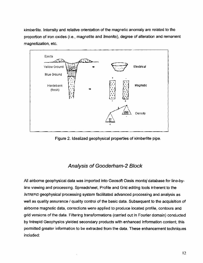
kimberlite. Intensity and relative orientation of the magnetic anomaly are related to the
proportion of iron oxides (i.e., magnetite and ilmenite), degree of alteration and remanent
magnetization, etc.
Ejecta
Yellow Ground
Blue Ground
Hardebank (fresh)
..
..
~ Electrical . .
T
~ "- ...... " I
, , Magnetic " , ... ' • , ! , , I
", '''' I , '; I' ... , , , f I (II ......
+
~~ Density
T
Figure 2. Idealized geophysical properties of kimberlite pipe.
Analysis of Gooderham-2 Block
All airborne geophysical data was imported into Geosoft Oasis montaj database for line-by
line viewing and processing. Spreadsheet, Profile and Grid editing tools inherent to the
INTREPID geophysical processing system facilitated advanced processing and analysis as
well as quality assurance I quality control of the basic data. Subsequent to the acquisition of
airborne magnetic data, corrections were applied to produce located profile, contours and
grid versions of the data. Filtering transformations (carried out in Fourier domain) conducted
by Intrepid Geophysics yielded secondary products with enhanced information content; this
permitted greater information to be extracted from the data. These enhancement techniques
included:
12
• Upward and downward continuations - the effect of shallow anomalies may be
suppressed when further detail on contributions from deeper sources is desired, or
conversely, shallow, high-frequency anomalies may be 'sharpened' by bringing them
'closer' to surface.
• Vertical and horizontal derivatives - eliminate long-wavelength regional effects, and
resolve adjacent features. Body outlines can also be more precisely identified by the
horizontal derivative.
• Analytic signal- (or total gradient) provides a quantity that is independent of the
direction of source magnetization and the direction of the Earth's field. Thus all bodies
with the same geometry will have the same analytic Signal, an obviously useful quality in
any interpretation.
The processed geophysical grids were further subjected to standard image processing
techniques using ER MAPPER; e.g., aeromagnetics and resistivity grids were 'fused' into a
single image using variable bands and colour look-up tables to provide increased target
quality and higher confidence through integration of all types of data. The final integration of
data and information was made using MAP/NFO GIS software, where the geophysical images
were overlain by layers or 'tables' of drainage, license permits, etc.
The primary objective of the geophysical interpretation was the identification and ranking of
possible kimberlite targets based on their magnetic response. Target selections made on
the basis of discrete anomalies identified from these enhanced grid images were
crosschecked on a profile-by profile basis. Essentia"y, the interpretation was seeking or
focusing on presumed geophYSical signatures that should occur over intrusive kimberlite
pipe-like bodies.
While the significance of basement structural control on kimberlites may be open to
discussion, the analysis of lineaments is of fundamental importance to understanding
geological structures and the stress regimes in which they are produced. Automatic analysis
of lineaments has previously been done with information mapped from remotely sensed
data, using either satellite-based imagery or aerial photographs. Potential field data may
also be analysed in terms of their lineament content. Edge detection and automatic trend
analysis using gradients in such data are methods for producing unbiased estimates of
13

sharp lateral changes in physical properties of rocks. The assumption is made that the
position of the maxima in the horizontal gradient of gravity or magnetic data represents the
edges of the source bodies, although this should be used with caution. Such maxima can be
detected and mapped as points, providing the interpreter with an unbiased estimate of their
positions. The process of mapping maxima as points can be extended to many different
levels of upward continuation, thus providing sets of points that can be displayed in three
dimensions, using the height of upward continuation as the z-dimension. There have been
recent developments and use of this method for interpretation of potential field data (e.g.
Archibald et aI, 1999 and Hornby et aI, 1999). Archibald et al refer to this process as
"multiscale edge analysis." Milligan (2003) more recently discusses the spatial and
directional analysis of potential field gradients and in particular, new methods to help solve
and display three-dimensional crustal architecture using a proprietary system of Euler
'worms.'
In multiscale edge analysis the assumption is made that lower levels of upward continuation
map near-surface sources while higher levels of continuation map deeper sources. This
assumption is generally true but must be treated with caution, due to the non-uniqueness of
potential field solutions. The INTREPID software's unique implementation of multiscale edge
analysis includes the use of Euler 'worms' which provide a view of structural geology
obtained directly from potential field geophysical data. The method is based on Fourier
techniques for continuation, reduction to pole and total horizontal derivatives coupled with
automatic edge detection.
Data Interpretation
Much reliance in the interpretation process for kimberlite targets is based on an analysis of
the horizontal gradient magnetic and analytic signal (total gradient) images. These have
proved most beneficial in previous exploration programs and are the primary tools for
identifying kimberlite intrusives directly from gridded aeromagnetic data sets. All anomalies
thus identified were crosschecked for their individual profile response and then tabulated.
The final edited list of targets identified from the Temagami East airborne geophysical data
is tabulated in Table 1 below.
14

An analysis of the airborne geophysics over Tres-Or Resources' Gooderham-2 property has
identified a total of 11 electromagnetic and/or magnetic targets that fit 'accepted' magnetic
criteria for kimberlite intrusions. Of these 11, none are ranked as high priority (rank = 1).
However, 5 are ranked as fair (rank = 3) targets. The remainder are felt to be less likely
representative of kimberlite intrusions (on a ranking scale of 1 to 5; 1 being most likely and 5
least likely) although all 'fit' accepted criteria for a kimberlitic, magnetic intrusion. It should
be pointed out that this geophysical-based interpretation relies on the magnetic
susceptibility of the kimberlite being different from the surrounding rock, and/or the electrical
conductivity/resistivity being Similarly distinguishable. Kimberlite is generally strongly
susceptible, having susceptibilities up to 6*10-2 SI (Litinskii, 196.3), which is why the
magnetic method is so successful. A diatreme is generally magnetic due to magnetite and
ilmenite being present in the unweathered kimberlite; significant weathering can reduce the
magnetic susceptibility. The susceptibility values of kimberlites can vary considerably. In
some kimberlites, there are multiple phases of intrusions or pyroclastic eruptions and each
phase can have a different magnetic susceptibility (Jenke and Cowan, 1994; Jansen and
Doyle, 1998). Some phases can appear to be non-magnetic. A number of the kimberlites in
the Lac de Gras area (Slave Province, NWT) in particular show reversed magnetic
anomalies, implying that there is strongly remanent magnetic material in the kimberlite.
Regardless of polarity, particular focus should be paid to targets assigned a rank of 1 to 3;
these are believed worthy of ground follow-up using additional geophysics and geological
mapping and/or geochemical sampling.
Experience by the interpreter, Christopher Campbell, and the literature confirm that it is
often the more fragmented diatreme and crater facies of kimberlites that have the lowest
resistivities or highest conductivities. Water (especially when saline or frozen) can also
make marked changes to the resistivity values. Resistivities vary strongly with only minor
changes in mineralogy such as clay, sulphides, oxide minerals and graphite. The lowest DC
resistivities are always recorded in the shallower more weathered kimberlite, and can be as
low as 5 ohm-m. A target model for kimberlites sought in this study was felt to be
reasonable at 100-1000 ohm-m.
15
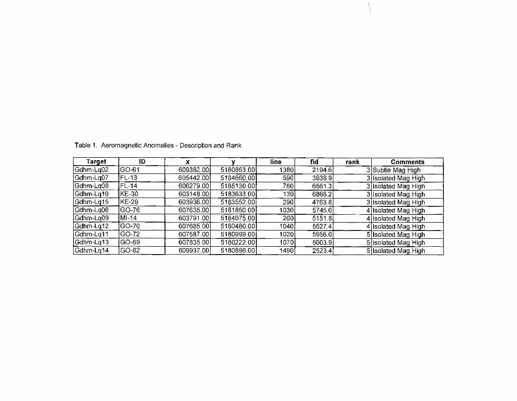
Table 1. Aeromagnetic Anomalies - Description and Rank
Target ID x y line tid rank Comments Gdhm-Lg02 GO-61 609382.00 5180853.00 1380 2194.6 3 Subtle Mag High Gdhm-Lq07 FL-13 605442.00 5184660.00 590 3938.9 3 Isolated Mag High Gdhm-Lq08 FL-14 606279.00 5185130.00 760 6561.3 3 Isolated Mag High Gdhm-Lq10 KE-30 603148.00 5183633.00 130 6868.2 3 Isolated Mag High Gdhm-Lq15 KE-29 603936.00 5183552.00 290 4763.8 3 Isolated Mag High Gdhm-Lq06 GO-76 607635.00 5181850.00 1030 5745.0 4 Isolated Mag High Gdhm-Lq09 MI-14 603791.00 5184075.00 260 5151.8 4 Isolated Mag High Gdhm-Lq12 GO-70 607685.00 5180480.00 1040 5527.4 4 Isolated Mag High Gdhm-Lq11 GO-72 607587.00 5180999.00 1020 5956.0 5 Isolated Mag High Gdhm-Lq13 GO-69 607835.00 5180222.00 1070 5003.9 5 Isolated Mag High Gdhm-Lq14 GO-62 609937.00 5180896.00 1490 2523.4 5 Isolated Mag High

610000
U'I -IX! o 8 o
605000 610000
Figure 4 - Summary Interpretation of Gooderham-2 Survey Block

Conclusions and Recommendations
The objective of this geophysical interpretation was the identification and priority ranking of
kimberlite targets derived from an airborne geophysical survey 'flown over the Gooderham-2
Block in October 2003. Results of this interpretation effort are listed in Table 1 and further
noted in Appendix A.
Follow-up testing of the geophysical anomalies ranked 3 and higher is recommended by
further geochemical indicator mineral sampling, where applicable, and ground geophysics
such as electromagnetics, gravity and magnetics, as well as, ultimately, by auger or drill
testing where those results warrant. The always ambiguous geophysical character of the
anomalies tabulated by this interpretation dictates that additional information, such as
positive indicator results, be confirmed before drill testing on anyone target be undertaken.
Regardless, in the event that any of the above-listed priority targets are indeed drilled as
kimberlite, then all airborne targets should be further reviewed in light of that success.
Ground follow-up geophysics should consist of electromagnetic profiling (either frequency
domain such as the MaxMin /I horizontal-loop system or time-domain such as the Geonics
Protem 57 system) as well as confirmatory magnetics. Gravity readings might also be
utilized in selected traverses across the 1-3 ranked targets.
The success of electromagnetic methods in detecting kimberlite depends on a distinct
contrast in conductivity of the kimberlite as compared with the surrounding material.
Kimberlites in the NWT have (although not in every instance of course) exhibit a moderately
conductive (about 100 to 1000 ohm-m) response. Fortunately, this is significantly more
conductive than the surrounding country rock in the NWT, which is typically greater than
10,000 ohm-m.
18

REFERENCES
Archibald, N., Gow, P. and Boschetti, F., 1999, Multiscale edge analysis of potential field data: Exploration Geophysics. 30, 38-44.
Brown. P, Cookenboo, H., Davis, C., Dunn, D. and Hickin, A 2002. Assessment Report on Till Sampling, Geological Mapping and Kimberlite Indicator Mineral Results.
Fesq H. W., Kable, E. J. D. and Gurney, J. J., 1975, Aspects of the geochemistry of kimberlites from the Premier mine, and other selected South Africa occurrences with particular reference to the rare earth elements: Physics and Chemistry of the Earth, vol. 9, p. 687-707.
Fiset, N. 2003. Report on a helicopter-borne magnetic and electromagnetic survey: Gooderham Block, Temagami Tres-Or Diamond Project, Aeroquest Limited, October 2003.
Gerryts, E., Diamond prospecting by geophysical methods-a review of current practice: in Mining and Groundwater Geophysics, Proceedings of the Canadian Centennial Conference on Mining and Groundwater Geophysics, October 1967, edited by L. W. Morely, p. 439-446.
Hornby, P., Boschetti, F. and Horowitz, F.G., 1999, Analysis of potential field data in the wavelet domain: Geophysical Journal International, 137, 175-196.
Jansen, J.C. and Doyle, B.J. 1998. The Tii Kwi Cho Kimberlite Complex, Northwest Territories, Canada: a Geophysical Post Mortem. Presented at the NWMA Practical Geophysics Short Course, December 1998. Northwest Mining Association, Spokane, Washington, USA
Jenke, G. and Cowan, D.R 1994. Geophysical Signature of the Ellendale Lamproite pipes, Western Australia: in Geophysical Signatures of Western Australian Mineral DepOSits. Geology and Geophysics Department, the University of Western Australia, publication 26, 403-414.
Litinskii, VA, 1963, "Measurement of magnetic susceptibility in prospecting for kimberlite pipes," The Mining Magazine, vol. 109, p. 137-146.
Lumbers, S.B., 1971. Geology of the Tomiko Area (West Half). Ontario Department of Mines and Northern Affairs, Geological Series, Preliminary Map P.678.
Macnae, J. C., 1979, Kimberlites and exploration geophysics: Geophysics, vol. 44, no. 8 (August), p. 1395-1416.
Milligan, P. R, Lyons, P. and Direen, N. G., 2003, Spatial and directional analysis of potential field gradientsnew methods to help solve and display three-dimensional crustal architecture: Australian Society of Exploration Geophysicists' 16th Geophysical Conference and Exhibition, February 2003, Adelaide, Extended Abstracts.
Mwenifumbo, C. J., Hunter, J. A M. and Killeen, P. G., 1996, Geophysical characteristics of Canadian kimberlites: in Searching for Diamonds in Canada, edited by AN. LeCheminant, D. G. Richardson, R N. W. DiLabio and K. A Richardson, Geological Survey of Canada, Open File 3228, p.237-240.
Sage, R P., 1996. Kimberlites of the Lake Timiskaming Structural Zone. Ontario Geological Survey, Open File Report 5937, 435 p.
Urquhart, W. E. S., Exploration geophysics and the search for diamondiferous diatremes: in Diamonds: Exploration, Sampling and Evaluation, Proceedings of a short course presented by the Prospectors and Developers Association of Canada, March 27,1993, p. 251-287.
19

APPENDIX I
Tres-Or Temagami Area Claim List
20

TOWNSHIP Claim Number I Claim Due Date
1 ANGUS~99775- t2002-AUG-06j2005-AUG-06 2 ANGUS--~~---~lT99776 2002-AUG-06 ..... -- 12005:AUG~-O~6----l 3 ANGUS"---- ! S 1199778 '2002-AUo:mr- - 1200S:AUG-06 4 ANGUS --.. -~ :STI99780 2002-AUG-06--+2005:'AUG~-O~6----l 5 iANGUS------ -----S lT99782~--L002~_:OO~:AUG-06 ---6· ANGUS'-S -3mf5"233 - - - -.-.7OO3=JU[:2T ·20Q5:JU[=21---~ -S 3005250- --2003.:JU[::2T··2000-JUI~-2"'1---I
8 ·--------;s,21971-3 ----LOO1J;O-CT:TO----~04-OCT_Ttr---- 9 ASKIN ---- ---ts-T:2197T6-----;LOQO:OCT_TO . 2000-AU~---
10 ASKINS 12197T7------T2000:0CT-162000-AUG-16 11 ASKIN S 12197:r6--------tmOO'=OCT_16 --lf2000-AUG-16 12 A IN S 1219727 12000=OCT-1O- I20OS:.AU"'GCC<-1"'6----l 13 SKIN" .S 1219739 1200FMAR=mr--- !:2005-MAR-09 14 ASKIN is 1219746 TZ001-=MAR=092005-MAR-09 15TASKIN is 121975r-------t;W01-MAR-09 2005-MAR-09
~6!A~----- '1 59' 2005-MAR-09 .. 17ASK 0 20 -OCT_.2I--~4-0CT-27 18 ASK 1246341 20 -QCT-27--i2004-0CT-27 19 ASKIN 12463422000-0CT-27 i2004-0CT -...,...,-----I 20 S 12 6343~-- 2000-0CT=2T-- 201)4-21 !ASKIN S 124 344 2000-NOV=OZ------ 2-000:."8 ...... -""'----1 22 A I S 1246345-----ZOOO;ocT=2 23 i S 1246-3~ ,2000-0CT=2T-- -05-
;~ !ASKIN -~~~i~:--- _~==~g~~rg""g""+"-'~"';---_-__ .-...... ' -26"ASKfN-- Sf246:w.r------izO'oo=OCT -27Z004=-0CI-27--
27 ASKTN ST:24(r.I9T~--2001=MAR=mr-- 00 -MAR-09 28 ASKIN ------- 30160112003=()CT-2-9----2005-0CT-29 29 ASKIN - ----.5 42UOl)55----~--2U04=O~l-nr ·~OCT-19 30 ASKIN -----54200'056- ----2004=OCT:.:r1- -2006-0CT-21 31 !BURNABY- -----'S-T24f989---- :200FMAR:n:r-- 2005-MAR-OZ--32BURNABy:n244817 ':200HilfAR:02- 2005-MAR:1JT-33. BURNABY-~---;"S1"244819 i:200FMA'R=OZ- 2005-MAR-:0:2 34. BURNABY '51244820 t:20nFMAR=o-:r-. 2005-MAR-=-02 35, BURNABY is 1244821 [:2O!J1:'MAR=o-:r- 12005-MAR=0:2--36 i BURNABY-- --TST244822 ~200FMAR:W- 12005-M' 371 BU~~ABY----iS 1244824 ;~qOFMA~ i 2005-M 38. BURNABY IS 1244825 :2001~.. .2005-M
-39TBURNABV - S 1244826 '2001-MAR-o-:r- - 0 5-M -4o+BURNABV ! 1 44827 ---- --:zooT -MAR-02 ,2005-MAR-=02-·-··· '4TlIDRNABV Is 1:244830 ----- ---I1'2001-MAR-02 i2005-MAR-02 --
42 BUABVSl"'244831 2001-=MAR=O:r i2005-MAR-02 . t----;4"'3irBURNA~--- S 1248930 ---flOO1-DEC:04 ! 2005-AUG~
44 BURNABY---S 1248937 _==tZOlJTTIEC:04 !2005-AUG-O.----I 45 BURNABV ................. • S 1248938 IZ01Jf:OEC:04 • 2005"'-AITT,.,,-.,.----1 46 ................. is 1248939 2001-DEC=04-------:-2 .. 005-AUG-04
47 §--S1248941 12001-~- "2\JOs::AUG:o;r---48 ABY1248942--------tzoor:0ec:Q4- -Z-005-AUG-04 .......... . 49 - .. B124894:r-----t200r:DEC-04 -.- -r:2005-AUG-04 __ _ 50 Y--1248944~- ----i200r:QEC:04- tZ005-AUG-04-5 --....... -..... ~ S124~---'zooT. :UEc::D4~ tzoo. S-AUa:1)4---52 ...- S-3-0O'21lf!1 '--~:ADG-oo .. --- ;ZO-OO-AUG:OO-53----ls-:r002T!1Y - 2002-ADG:mr---- ~S-AUG-06 54 ... _ .... ---T~n002113-------7002:P;UG:06---"200S-AUG-06
55 I BUR ... N. ABV.
E
---- -T! .. -:m021. '.15-.·---;.2002:..... .-.. AU. G:::-mr.-·-·--· .. ·.;zoQS-AUG-06 .... -.. --. 56 ----3005lO9"-~-700'3.:JUN-f2-- :ZOOs:JUf'r-T2-- -----57 LDRIDG ' T22T76l -----+2003-JUN:20--- f2005-JUN-26 __ 58 ELDRIDG~----- !r1240635 .200r:M}S;R:ug-- r2005-MAR-09--
1-----5=9 frETDHlotre--- S 1241990 -i200r:MAR-\J9--- 2005-MAR-09 60 i ELDRIDGr-" 1243254 200l=SEP=Q7----- 05-SEP-07 6fELDRfDGE S 1243266 ---~O 1- -1 2005-AuG-:T7 62 44823~00T- 05-MA .:::og-~ .. 63 ST244832 .:2001-MAR=mr--- ZO05:TlIA..".",,---1 64' ELDRIDGF- I Sl2448:3':f' t20m=MAR=mr- 2005-MAR-09
-- 65 ELDRIDGE S 1244834 -2Ql)-FMAR~mr- 2005-JIIIAR=09 66E~-·---iS1248441 -SEP=07----
f--;6'""7cCtELDRIDGE S 1248906 AY-30 -- 68 ~- ,S 1248911 2005-A G-=-04---69 URTDGF-----·---rs12489'f2 ·2001-DEC'::04--- 5-AUG-04-----
;~~-=:--1IT~::~~! -----~~=-=--20~;~~g~-...
C--~~ TOWNSHIP i Claim Number Recording
Date Claim Due Date
~ I I _
r--72 ErDRTDGE S 124891S :2001-DEC-04 200S-AUG-04 73 ELDRIDGE S 1248916 [2o01-DEC-o4----j201m:.AlfG.:-o4----74 ELDRIUGE---IST248979-~-~-!2001-DEC-04 200S-AUG-04 7S ELDRID-GE-- S 1248980 2001-DEC-04 200S-AUG-04
J--~7"'6-+rE"LD"'R"'I"""UG;~It:---··-·- S 1248997 2001-MAY-30 2005-MAY-30 77 ELDRIDGE I::; JOOOLJS 2003-JUN-26 200S-JUN-26 78 t:LuKIDGE S 300S238 12003-JUN-26 200S-JUN-26 79 ELDRIDGE 1 S 3000g-36~-------[2003--JUN-26 200S-JUN-26
--
80 ELDRIDGE S 300S837 12003-JUN-26 200S-JUN-26 81 ELDRIDGE ---------- -S-:rOT4T76 2004-0CT-OS 2006-0CT-OS 82 ELDRIDGE S 3014177 _ 12004-0CT-22 2006-0CT-22 83 ELDRIDGt: -----S4"2lJOoST----i2-mJll-":OCT-=-2T-- 2-006--=-OC'F2-1--84 ELDRIDGE S 42000S4 2004-0CT-21 2006-0CT-21 8S t-LEITISTI"41T2"5-- --- --I2-0-00:'O-CT-TS- ---- --:ro-Oo-::AUG:'~~-86 FLETT S 1241127 i2000-0CT-16 200S-AUG-16 87 FLETT S 1241128 !2000-0CT-16 - 1200S-AUG-16 - _-
1--88 FLETT ,::; 1241130-2-000-0CT-=-TO-- ·2005-AUG-16-----89 FLETT ----- - -is 124 ff3T - ~200D=-O-CT:.T6--TmJ5~AOG:.lo ---90 FLETT ,S 1Z41TJ3 --H-2000::OCT:'fS- - -H2-0-0o::AUG~To-- ---91 FLETT~---+S12'fff30--- INOO-UCTTO --1200S-AUG-16 -~ 92 FLETT IS 1243249 - 2001-MAR-OS i200S-MAR-OS 93 FLETT :S 12432S0 2001-MAR-06 1200S-MAR-06
--94] FLETT is 1243251 2001-MAR-06 !200S-MAR-06 - -951HETI -- ---TST246305-----'2000--=-0Cl-2T---~2D05--=-O"CT:.-:27---
~ 96 1 FLETT S 3001133 2002-NOV-20 i 200S-MAR-09 971 FLETT S 3005230 ~---------I-»2"'00""3.--JlTJU1TJiL---,--OVf2 ,2005-JUL-02 98 FLETT S 30UOL01 2u03-JUL-02 200S-JUL-02 99 FLETT S 42""OlJQi51-- 2004-0C 1-21 '2006-0CT-21
100 GLADMAN S 1219721 20u1-MAR-02 200S-MAR-or------101 GOODERHAM S 12410S4 -- 2000-0-CTl-6-- 200S-AUG-16 102 GOODERHAM S 124S26S--rw-01-AP"RT7 2004-0CT-18 103 GOODERHAM S 124S294 2001-APR-17 2004-0CT-18 1041 GOODERHAM --"ST24S29S 2001-AP"R=17--- --12-004-0CT-18 10S GOODERHAM ,S 1245296 2001-APR-17 2004-0CT-18 1061 GOUDERHAM 18"1245020------ 2003-::;t:P-02 @OS-SEP-02
---rO? jG-n-ODERHAM ts 1246313 --- 2000-0CT7fO ----- -12005:AUU~10 -- - . --wSTGmmERHAM-lS----r2403'f5- --- fOOO-OCT-16 T2W5-=AUG::f6-----
109 GOODERHAM is 1246316 ---,2000::OCT-16 ,200S-AUG-16 --110 GOODERHAM S 1246317 12000-0CT-16200S-AUG-16 111 GOODERHAM S 1246319 12000-0CT-16 200S-AUG-16
- 112 GOODERHAM IS 1246321 12000-0CT-16 ,200S-AUG-16 113 GOODERHAM -j S 1246322 12000-0CT -16 200S-AUG-16 114iGOODERHAM _ S 1246323 __ ~000-OCT-16 200S-AUG-16-115; GOODERHAM --- S-"1-246-:r24 __ u ---- --I 2-000~O~CT:1O "--". 2005-AUG-16 1161GOODERHAM - S124632-5-------:z-oo-0-0-CT:fO ---- 200S-AUG-16 -~
117iGOODERHAM S 12463262000-0CT-16 200S-AUG-16 --118; GOODERHAM ---"5"1246334 - -----L"OOO-OCT-=--1O 200S-AUG-16 119, GOODERHAM - S f2"46-:r:r5-TO-OO:'OCT-nr - -- 2W5-::AUG~1O --120 i GOODERHAM S 1246371-- -u-~--;2000-NOV:'W 2uOS-SEP-02 121 GOuuERHAM S 12463r22000-NOV-02 200S-NOV-02 122 GOODERHAM "S"T24o373----~2-0o0-::w-OV:nT----- 2005--=-S-E-p:()T------123,GOODERHAI\7I---~ S 1246374 2000-NOV-02 200S-NOV-02 124: GOODERHAM S 124637S ; 2000-NOV-02 2005:.l\rOv=-OZ--------12S GOODERHAM S 1246376 .2000-NOV-02 2005-SEP-02 126 GOOUERHAM S 1246377 i2000-NOV-02 200S-SEP-02 127; GOODERHAM ::; 12463tS-------t21ro-O:'l;;JOV=-02--- 2lJ05-NOV-02
-- 1281' GOODERHAM S 1246380 : 2000-NOV-02~--2000-SEp"-=o;r-------129IGOODERHAM~---"S12489842001-APR-17 2004-0CT-18
t- 130 GOODERHAM 1 S 1248985-H--- -- 2-00-P\P-R~1T·· --- 2004-m;-r:-ra----~ ---131 G-OOIrE-R~ !S 1248998 ;2001-APR-17 12004-0CT-18
- -----IS--- ---------- --- -----h------- ------------- -- ---1---- ---- ------ ---- ---
~;; gggg~~~~~-- . --r
l
: s~~-~-;~-~~_=__==!~~~~~J=20f~~~ __ t~:~~~~-~--t-- 134 GOODERHAM S 300S2312003-JUL-21 200S-JUL-21
13S GOODEKHAM ------r~n-0-0-sZor---12(f03::Jrr[:2f-- Z005-JUI~21 .. 136 GOODERHAM S 3009022 ~4-FEB-11 2006-FEB-11 137 GOODERHAM IS 300902S 2004-FEB-11 2006-FEB-11 138 GOODE-RHAM S 3009026 ! 2004-FEB-11 2006-FEB-11
t--139GOODERHAM is 3009793 -- i2lJo3:.t)CT.:-m)"- -.- "2lJlJ5--=-o-CT.:no--140 GOODERHAM~---rS 3009794 i2003-0CT-06 200S-0CT-06 141 GOODERHAM is 3017169 --;-ZO-04-I\7IAR--3-0---- 2-006=-MAR="30-----142 GOODERHAM S 42001l54---------I-TOO4:Nov::Oz---2-mr6:.NDv:02------
TOWNSHIP Claim Number 1 ! Claim Due Date
143+~L~ S 1245525 :20IT:5.:sEP:02 :2005-SEP-02 144 I HAMMELL S 3005234zmJ.<r:O'"E.C-06 .2006-DEC-06 45 i HAMMELL IS~3\fO-giJ(f2 ~ ~ ~ 2004-FEB=IT -- ~L<r06~FEH~lr 46TRAMMElr--~~-lS300~~-----_W04-FEtPfr~~~~ .2006-FEB-11
. L _u_ rS31I09004~~~ ~~-- Z004-FEB-f,----{21:riJtr:-FEB-1l
~--~:~I~~~~~~~ ----1;Igg~-g~ -~-~-j~~i-~= 2006-FEB- 1
150 iMMEL[- ~-~~S' 3009007~~ ~~-+2004:FEB:n 2I10i;{ ...... ~CA~ ~-.-~ ---]
151! HAMME1r~ -S 3009008~ -FEB-n~~--~ 2006-FEB-11 152 AMMELL S 3009009 4-FEB-11 2006-FEB-11 153 HAMMELL S 300 010 2006~fEB:ll-~~~
154 AMMELL S 3009011 2006-FEB-11 1551 AMMEL[-~-~-~2 -~-2006~FEB:1TA1---l 156 AMMEL[~~~----~OO1m13~FEtr:rr--
157 AI\~MEI:C~-- ~--~-rs-"3U09014~~~,~FEB-1T-----158fHAMMELL Is 3009015~~~~~ -f2000-FEH:~--
159 LL S 300 016 - - ~ -~FEB--::n--160 HAMMELL IS 3009017 -1-zmr4-rre:11--~ 2!006-FEB-11 161 A M L _ ~tS3009018 !2004-FEB-11 !2006-FEB-11 162 A M IT---~~IS~3W9019 12004-FEB-11 '12006-FEB-::-rr-~~~ 163 A LL~~S3009020 12004-FEB-112006-FEB-11 ~~~~ 164 L~~S3009021-~----T2U04-FEB-11 12006-FEB-11 ~~~~
165 L ~rS--:3W9~-~ !Z004-FEB-11 20UO:FEtf-l1--166 3009 2004-FEB~r~---- 2006-FEB-11 167 HAMMELL .S 3009 ,--r;w04-FEB-=n- .2006-FEB-1r--168 HAMMELL-----+5 420 1 104;;DEc:1O~--.-+ZOO6=OEC-
~ 1691 HAMME[[-~- • S 420;1 ~~ 04:[)EC:162006~OE~-~-~170 rHA.MME[~:--- S :§03~ 98- -- _ -- 2004-DEC:16-Z006=OEc=ro----
171 IHARTLES 12Z36gg-~·-~ -2OO1-MAR-09 -2005-MAR-U9 _n ~---
172THARTLE~-- _S 1223690 ~ 21105- AR-09 173HARTLES 1223691 2001:MAR·09 2005-MAR-09
17 4 HARTLE~~-------·--;S'1240636 -- ·-rr2-01ls=-MAR-=-09---~-----
f75HARTCE--- --j2005-MAR-05 176 E _ MAR-05 177 E 2005-MAR-05 178' E 5-MAR-05 179 i ETS1243L52-~~~-~~~'20 5-MAR-06 180! RTIE----·~~-lST:!43203-~~-~ 2001-MAR-06 !2005-MAR-06 18 E!S1243E"mr------ i 5-MAR-05 1821 E --~~~TS12~--~+:2001-MAR-06 12005-MAR-06 183 i E ~~rS1249m--~~~. 2001-MAR-06 12005-MAR"-0""6~--] 184. HARTLE------j S 3005173 ~~~~~~ i 2003-MAY -22 '2 0 -MAY -22 185 L-E--- -~rs-3OO5174~~~~~~ 12003-MAY -22 i 05-MA Y -22 186 HARTLF !S 3009028 ~~~~~~2004-FEB="03 '2006-FEB-03 187. HEBERT 'S2448T1T----~-~_2001-MAR-02. 2005-MAR-:02-----188. HEBERT : S 1244812!2001-MAR-02 • 21fCJ5-=-
189"HEBERT : S 1244813!Zmrr=MAR-=O:! -'->,; 2"""''''''Al''f"?f''>---l -19OTREBERT --15124481"4- 2001-MAR=UT -'2000-lIIIAR-=-az-·
HEBERT ----rs124481o-~-~-rzmrr:M""AR::02 2005-MAR-02 FrEBERr-~----iS 1244816 ~---2001-MAR-02 20iJ5=IIifAR-O-Z---
BERT IS 1244818 2001·MAR-02--;2-o{f5~I\IIAR-02~
BERT IS 124526g- --ZO-02:APR-09 - 1201)4:0CT-01--~ BE~~ is 1248917-i20-01~IJE-C-Otr· 201l5:A~-
'1"'9"6 Tr! H".E'1"\BCFEnR....-T~-~~~~~ ~ I S 1248918 12001-DEC-04 2-(f(f5:AU-G~04-~--1971 HEIffO'Rr --~-~-~-TS-1248919---- 12001-DEC-04 2005-AUG-04
-1981 AEBERr-------tSt24B920---~ 12001-DEC-04 2005-AUG-04 1991 HEBEln-- --~---rsl241mZr----~~-t2001-DEC-04 2005-AUG-04 200 EBERT S124892Z--- - c:D4~--- 2005-AUG-04 201 HEBERT S124892 - c:D4--1~2-oUO-AUG-04
202 HEBERT S124892 - C:-04 ~ i2005-AUG-04 --2031 HESEORT---------rsrt248-gzo---- .2005-AUG-04--204 ERT------T~rT24ImZO_~- 001-DEC-042005-AUG-04
205 HEBERT1s1z41m21--~ :cror:m -04 2005-AUG---206REBERT~-- --is 1248928- OOf:DEC:04 -2005-AUG-04
207 H (J----~~-----iS124lr929 2001-DEC-04 . 2005-AUG-04-~~· 208 HEBERT 'S2489472004:0CT~~--·---~
209 ERI-- .S 12489~~-2002-APR·09 12004-0CT-01 210 HEBERT -T248tl50--- -R=09~--~--211 BERT 002-APR-09 -F20-01r:Ap-~-212 H BERT--- -"-~S-T24gg-53---~ 2 0 - 12005:AP~--213TFrEBERI---~48955 :mr-~-:2004-0CT-01 ~~-~-

TOWNSHIP • Claim Number· ecording
Date I Claim Due Date

TOWNSHIP Claim Number .• Claim Due Date

APPEND/XII
Aeromagnetic Anomaly Identification - Profile and Map Responses
21
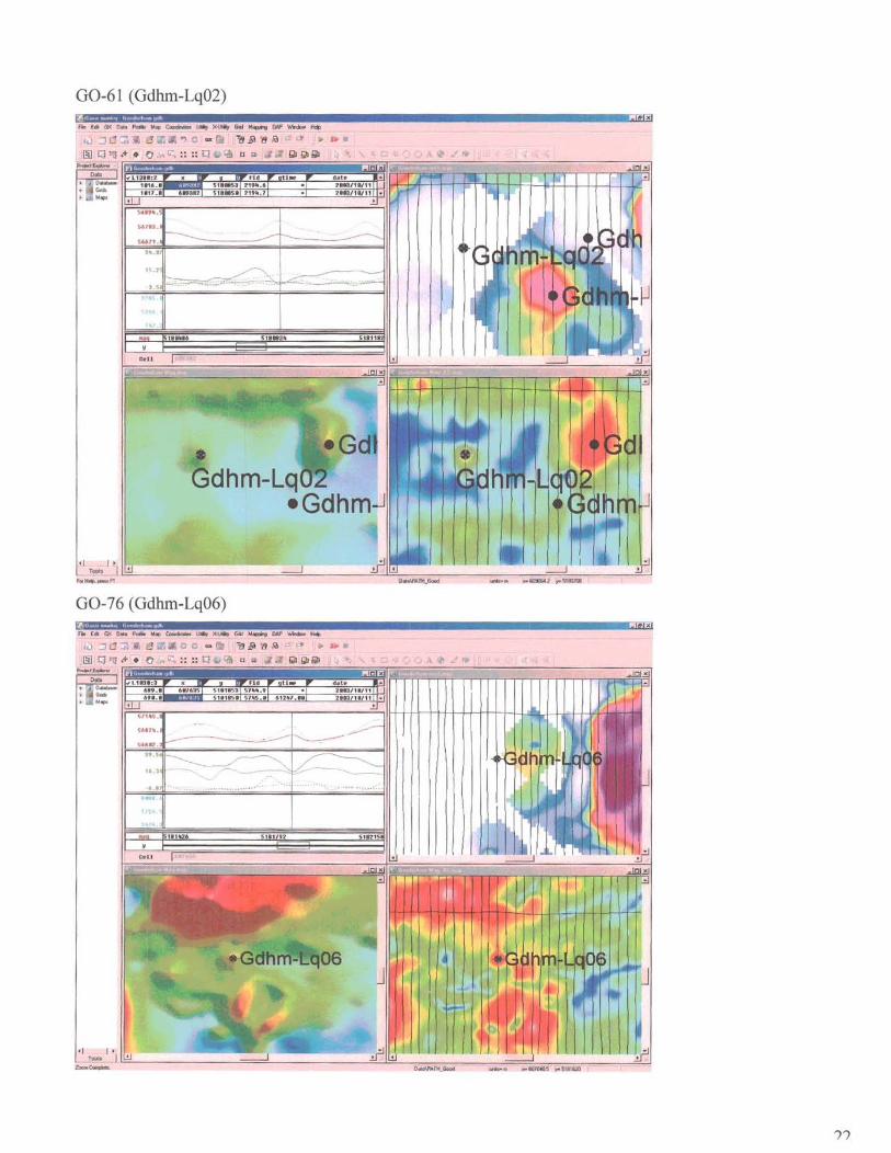
GO-61 (Gdhm-Lq02) -~ .
Fie Edl It< 0 ... ~ W. ~ lJIM, )C.I.JIip GId 1oI4ClJl1"9 (W' \IInb¥ ~
.r. ... ~ GI i!$l/9!il •
GO-76 (Gdhm-Lq06)
Fit r* (i.\( D_ Pd1a Mtp ~ lIIIr xu., (iii:! .. ~ ON' ..............
Hl.:l tJ ':I1 ", - 111 "'II~lI'i
e G' :::: Q
~ I I • ~::. I~----------------~==~------------__ -=~~ __ ~~~~ ______ ;:====~~~~ ______ ~-J
II
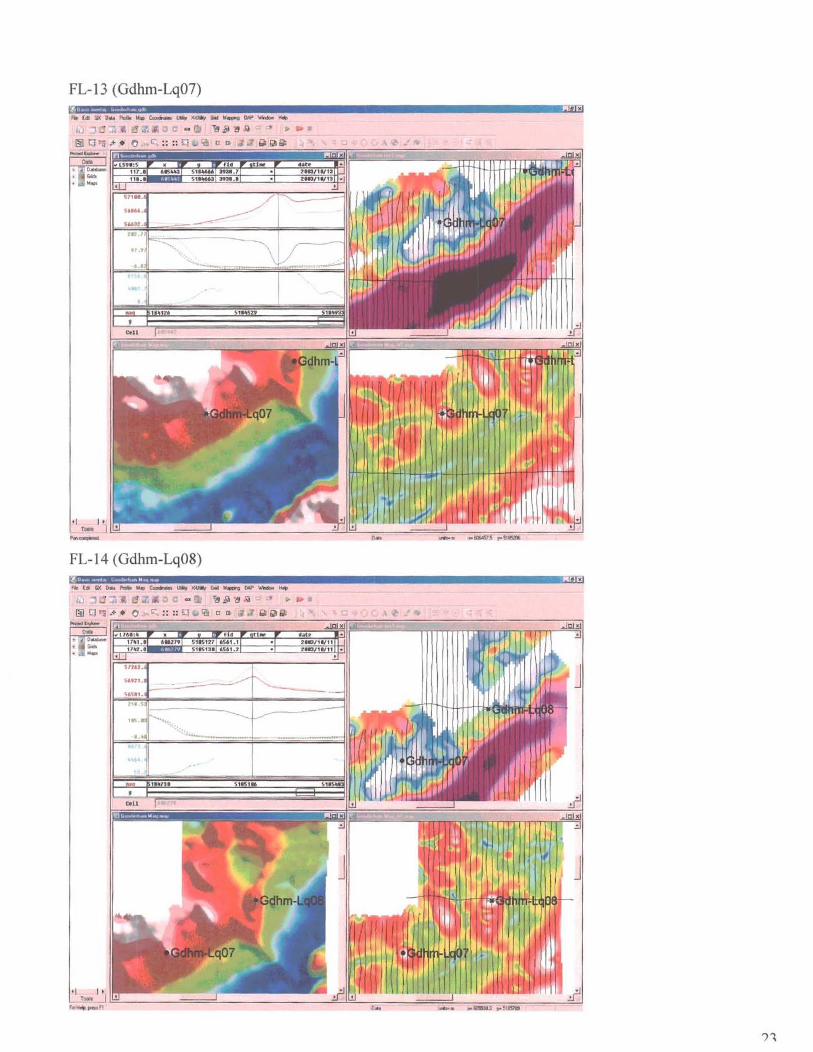
FL-13 (Gdhm-Lq07)
flI [cit so; OM Pdt M~ ~ IMr X~ lim ~ CAP ~ ...
r.l.J .:l :a " " 0 i!.Iil~l'I d'
e c:-,, :::: :;:j • bII bllbll
FL-14 (Gdhm-Lq08)
FiI Es GX 0 .. PI6 M.Ip ~ t.MI!P~G.t ~CW' .......... ~
lJ:.:l d :R u Ji .. ~ rll.lil;!,!;j , .~ .
11
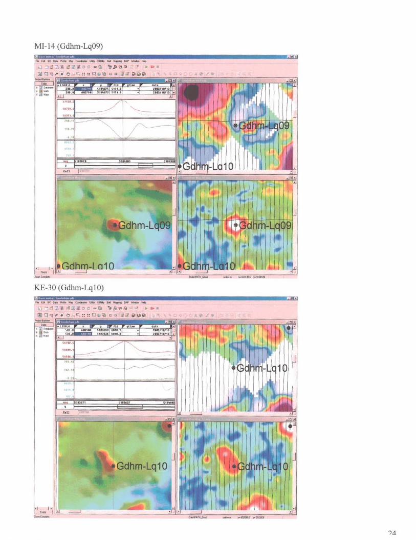
MJ-14 (Gdhm-Lq09)
Iil j t3 :;\ .. .:; I.
~ ~~ ~~~K~e~~:;~;;i!~~~~~~;;~~liiiiiiiifll=r~~~jj~~fTTl:r1
'I I. r~ I ~ ____ ~==~ ________________________ ~~~~~==~ ____ ~ __ ~~~~=-______ ~~ --
KE-30 (Gdhm-Lq 10)
, I I. r~ I ~ __ ~==~ __________________________ ~~~~~~~ ____ ~ __ ~~~~=-______ ~~ --

00-72 (Odhm-Lq l l)
FltE. Ii< D .. A."-' ~ _xallJl GId~o;,p\lJiodM~
~ C ::8 .5 ~ /)I ~jI~1i ~ ••
• C. :: :: Q ~ 0 ~ .z " ~ ~ &b
'I I ' T"* I ~ ________________ ====~ ____________ ~~~ ______________ ~====~ __ ~ ________ ~~
f fJJ __ ~n
00-70 (Odhm-Lq12)
Gdhm-Lq12
·1 I ·
~~~nl~----------------~==~-------------=~~~~~--------~======~===-------~~
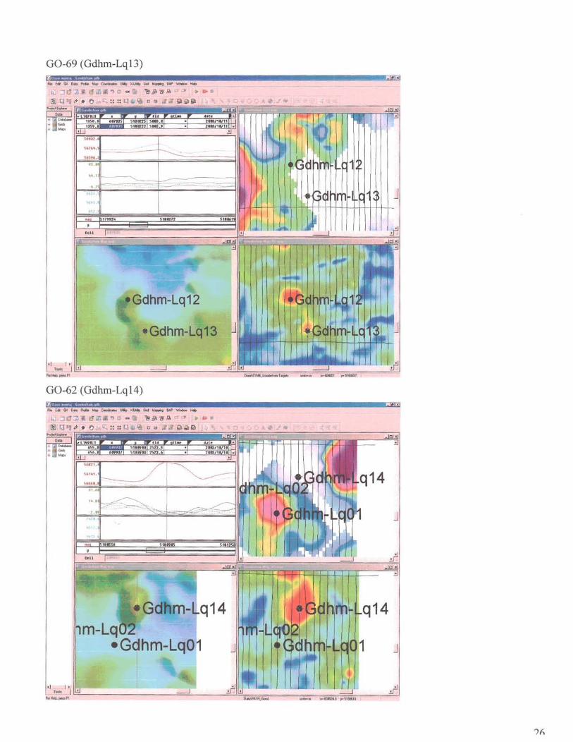
00-69 (Odhm-Lq13)
.Gdhm-L 13
00-62 (Odhm-Lq14)
q14
J
-I I-T_ J
FGI ... ~n =-------------=='------''''-'=:c-=:::-:--:----,.------::::::-:-===:'::-------'::!..-J
Ih
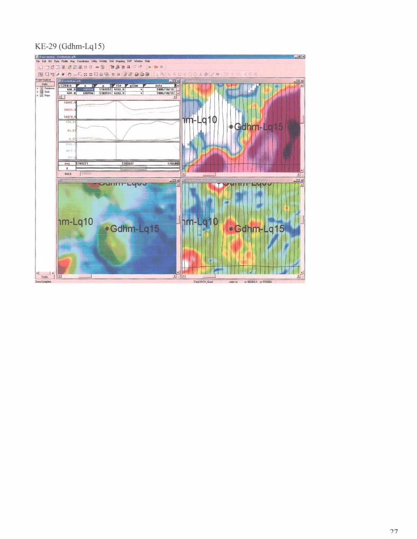
KE-29 (Gdhm-LqlS)
Fie Edi GX 0.. fWIe ~ Cocnht. lhIt.r x.wa, G.d W~ OAP ...... H~
.:] t1 ~ [!.. u ~ ""~!J,\I " I~ •
• ~ QlIiIl
...
41 I ' ~ ... I~----~==~-----------------------=~=-~~~==----~--~==~~=-------~~ -,,-
')7