report on roller-compacted mass concretedl.mycivil.ir/dozanani/aci/aci 207.5r-11 report on...
TRANSCRIPT

ACI 207.5R-11
Reported by ACI Committee 207
Report on Roller-CompactedMass Concrete

Report on Roller-Compacted Mass Concrete
First PrintingJuly 2011
ISBN 978-0-87031-277-9
American Concrete Institute®
Advancing concrete knowledge
Copyright by the American Concrete Institute, Farmington Hills, MI. All rights reserved. This materialmay not be reproduced or copied, in whole or part, in any printed, mechanical, electronic, film, or otherdistribution and storage media, without the written consent of ACI.
The technical committees responsible for ACI committee reports and standards strive to avoid ambiguities,omissions, and errors in these documents. In spite of these efforts, the users of ACI documents occasionallyfind information or requirements that may be subject to more than one interpretation or may beincomplete or incorrect. Users who have suggestions for the improvement of ACI documents arerequested to contact ACI via the errata website at www.concrete.org/committees/errata.asp. Properuse of this document includes periodically checking for errata for the most up-to-date revisions.
ACI committee documents are intended for the use of individuals who are competent to evaluate thesignificance and limitations of its content and recommendations and who will accept responsibility for theapplication of the material it contains. Individuals who use this publication in any way assume all risk andaccept total responsibility for the application and use of this information.
All information in this publication is provided “as is” without warranty of any kind, either express or implied,including but not limited to, the implied warranties of merchantability, fitness for a particular purpose ornon-infringement.
ACI and its members disclaim liability for damages of any kind, including any special, indirect, incidental,or consequential damages, including without limitation, lost revenues or lost profits, which may resultfrom the use of this publication.
It is the responsibility of the user of this document to establish health and safety practices appropriate tothe specific circumstances involved with its use. ACI does not make any representations with regard tohealth and safety issues and the use of this document. The user must determine the applicability of allregulatory limitations before applying the document and must comply with all applicable laws and regulations,including but not limited to, United States Occupational Safety and Health Administration (OSHA) healthand safety standards.
Order information: ACI documents are available in print, by download, on CD-ROM, through electronicsubscription, or reprint and may be obtained by contacting ACI.
Most ACI standards and committee reports are gathered together in the annually revised ACI Manual ofConcrete Practice (MCP).
American Concrete Institute38800 Country Club DriveFarmington Hills, MI 48331U.S.A.Phone: 248-848-3700Fax: 248-848-3701
www.concrete.org
ACI 207.5R-11 supersedes ACI 207.5R-99 and was adopted and published July 2011.Copyright © 2011, American Concrete Institute.All rights reserved including rights of reproduction and use in any form or by any
means, including the making of copies by any photo process, or by electronic ormechanical device, printed, written, or oral, or recording for sound or visual reproduc-tion or for use in any knowledge or retrieval system or device, unless permission inwriting is obtained from the copyright proprietors.
1
ACI Committee Reports, Guides, Manuals, and Commentariesare intended for guidance in planning, designing, executing,and inspecting construction. This document is intended for theuse of individuals who are competent to evaluate thesignificance and limitations of its content and recommendationsand who will accept responsibility for the application of thematerial it contains. The American Concrete Institute disclaimsany and all responsibility for the stated principles. The Instituteshall not be liable for any loss or damage arising therefrom.
Reference to this document shall not be made in contractdocuments. If items found in this document are desired by theArchitect/Engineer to be a part of the contract documents, theyshall be restated in mandatory language for incorporation bythe Architect/Engineer.
Report on Roller-Compacted Mass ConcreteReported by ACI Committee 207
ACI 207.5R-11
Roller-compacted concrete (RCC) is a concrete of no-slump consistency inits unhardened state that is typically transported, placed, and compactedusing earth and rockfill construction equipment. This report includes theuse of RCC in structures where measures should be taken to cope with thegeneration of heat from hydration of the cementitious materials and attendantvolume change to minimize cracking. Material mixture proportioning,properties, design considerations, construction, and quality control arecovered.
The materials, processes, quality control measures, and inspectionsdescribed in this document should be tested, monitored, or performed asapplicable only by individuals holding the appropriate ACI certificationsor equivalent.
Keywords: admixtures; aggregates; air entrainment; compacting;compressive strength; conveying; creep properties; curing; lift joints;mixture proportioning; monolith joints; placing; shear properties; vibration;workability.
Chapter 1—Introduction, p. 21.1—General1.2—What is roller-compacted concrete?1.3—History1.4—Advantages and disadvantages1.5—Performance of RCC dams
Chapter 2—Notation and definitions, p. 92.1—Notation2.2—Definitions
Chapter 3—Materials and mixture proportioningfor roller-compacted concrete, p. 9
3.1—General3.2—Materials3.3—Mixture proportioning considerations3.4—Mixture proportioning methods3.5—Laboratory trial mixtures3.6—Field adjustments
Chapter 4—Properties of hardened roller-compacted concrete, p. 19
4.1—General4.2—Strength
Jeffrey C. Allen Teck L. Chua David E. Kiefer Henry B. Prenger
Terrence E. Arnold Barry D. Fehl Gary R. Mass Ernest K. Schrader
Randall P. Bass John W. Gajda Tibor J. Pataky Stephen B. Tatro
Anthony A. Bombich Rodney E. Holderbaum Jonathan L. Poole Michael A. Whisonant
Note: ACI Committee 207 would like to acknowledge Tim Dolen and Nate Tarbox for their significant contributions to the document.
Timothy P. DolenChair
Consulting members
Eric J. Ditchey William F. Kepler
Brian A. Forbes Tom W. Read*
Richard A. Kaden
*Deceased

2 REPORT ON ROLLER-COMPACTED MASS CONCRETE (ACI 207.5R-11)
4.3—Elastic properties4.4—Dynamic properties4.5—Creep4.6—Volume change4.7—Thermal properties4.8—Tensile strain capacity4.9—Permeability4.10—Durability4.11—Density
Chapter 5—Design of roller-compacted concrete dams, p. 27
5.1—General5.2—Foundation5.3—Dam section considerations5.4—Stress and stability analyses5.5—Temperature studies and control5.6—Contraction joints and cracks5.7—Galleries and drainage5.8—Facing design and seepage control5.9—Spillways, aprons, and stilling basins5.10—Outlet works
Chapter 6—Construction of roller-compacted concrete dams, p. 39
6.1—General6.2—Aggregate production and batching and mixing plant
location6.3—Batching and mixing6.4—Transporting and placing6.5—Compaction6.6—Lift joints6.7—Contraction joints6.8—Forms and facings6.9—Curing and protection from weather6.10—Galleries and drainage
Chapter 7—Quality control of roller-compacted concrete, p. 56
7.1—General7.2—Activities before RCC placement7.3—Activities during RCC placement7.4—Activities after RCC placement
Chapter 8—References, p. 668.1—Referenced standards and reports8.2—Cited references
CHAPTER 1—INTRODUCTION1.1—General
Roller-compacted concrete (RCC) is probably the mostimportant development in concrete dam technology in thepast quarter century. The use of RCC has allowed many newdams to become economically feasible due to the reducedcost realized from the rapid construction method. It also hasprovided design engineers with an opportunity to economicallyrehabilitate existing concrete dams that have problems withstability and need buttressing in addition to improvingexisting embankment dams with inadequate spillway
capacity by providing a means by which they can be safelyovertopped. RCC has allowed new embankment dams tooptimize spillway capacity in over-the-embankment-typeemergency spillways (Hansen 1992).
This document summarizes the current state of the art fordesign and construction of RCC in mass concrete applications.It is intended to guide the reader through developments inRCC technology, including materials, mixture proportioning,properties, design considerations, construction, and qualitycontrol and testing. Although this report deals primarily withmass placements, RCC is also used for pavements (refer toACI 325.10R) and for dam stability improvement and asembankment dam slope protection (United States Society onDams 2003).
1.2—What is roller-compacted concrete?ACI Concrete Terminology (2010) defines roller-
compacted concrete (RCC) as “concrete compacted by rollercompaction; concrete that, in its unhardened state, willsupport a roller while being compacted.” RCC is usuallymixed using high-capacity continuous mixing or batchingequipment, delivered with trucks or conveyors, and spreadwith bulldozers in layers prior to compaction with vibratoryrollers (Fig. 1.1). Because of RCC’s zero-slump consistency,subsequent lifts can be placed immediately after compactionof the previous lift. RCC can use a broader range of materialsthan conventional concrete, and derives its strength anddurability from a mixture philosophy that relies on using justenough paste volume to fill the aggregate voids and no morewater content than what is needed for proper workability.
1.3—HistoryThe rapid worldwide acceptance of RCC is a result of
economics and of RCC’s successful performance. A bibliog-raphy of dams constructed is available from the InternationalCommission on Large Dams. Other listings of damsconstructed can be obtained from the United States Societyon Dams (2003) and from the U.S. Army Corps of Engineers(USACE), EM 1110-2-2006 (USACE 2000). During the1960s and 1970s, applications of RCC materials led to thedevelopment of RCC in engineered concrete structures. Inthe 1960s, a high-production no-slump mixture that could be
Fig. 1.1—RCC compaction with dual-drum, vibrating roller(Serra do Facõo Dam, Brazil, 2008).
REPORT ON ROLLER-COMPACTED MASS CONCRETE (ACI 207.5R-11) 3
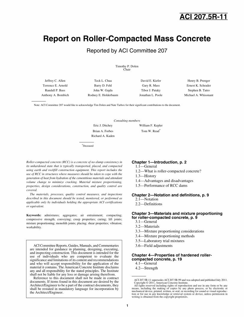
spread with bulldozers was used at Alpe Gere Dam inItaly (Engineering News Record 1964; Gentile 1964) and atManicougan I in Canada (Wallingford 1970). The mixtureswere consolidated with groups of large internal vibratorsmounted on backhoes or bulldozers.
Fast construction of gravity dams using earthmovingequipment, including large rollers for compaction, wassuggested in 1965 as a viable approach to more economicaldam construction (Humphreys et al. 1965). The fastconstruction method did not receive much attention until itwas presented for the “optimum gravity dam” (Raphael1971). The concept considered a section similar, to but withless volume than, the section of an embankment dam. Duringthe 1970s, a number of projects including laboratory anddesign studies, test fills, field demonstrations, nonstructuraluses, and emergency mass uses were accomplished andevaluated using RCC. These efforts formed a basis for thefirst RCC dams, which were constructed in the 1980s.
Notable contributions were made in 1972 and 1974 by theTennessee Valley Authority (Cannon 1972, 1974). The U.S.Army Corps of Engineers conducted studies of RCCconstruction at the Waterways Experiment Station in 1973(Tynes 1973) and at Lost Creek Dam in 1974 (Hall andHoughton 1974). The early work by the U.S. Army Corps ofEngineers was in anticipation of construction of an optimumgravity dam for Zintel Canyon Dam (Sivley 1976). ZintelCanyon Dam construction was not funded at the time, butmany of its concepts were carried over to Willow CreekDam, which was completed in 1982 and became the firstRCC dam in the U.S.
Developed initially for the core of Shihmen Dam in 1960,“rollcrete” was used for massive rehabilitation efforts atTarbela Dam in Pakistan beginning in 1974 (Hansen andReinhardt 1991). Workers placed 460,000 yd3 (350,000 m3)of RCC at Tarbela Dam in 42 working days to replace rockand embankment materials for outlet tunnel repairs. Additionallarge volumes of RCC were used later in the 1970s torehabilitate the auxiliary and service spillways at TarbelaDam (Johnson and Chao 1979).
Dunstan (1978; 1981a,b) conducted extensive laboratorystudies and field trials in the 1970s using high-paste RCC inthe UK. Further studies were conducted in the UK and led tomore refined developments in laboratory testing of RCC andconstruction methods, including horizontal slipformedfacing for RCC dams (Dunstan 1981a,b).
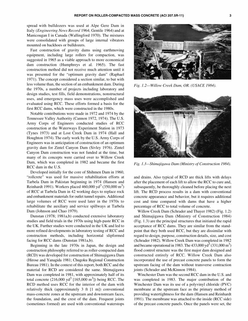
Beginning in the late 1970s in Japan, the design andconstruction philosophy referred to as roller-compacted dam(RCD) was developed for construction of Shimajigawa Dam(Hirose and Yanagida 1981; Chugoku Regional ConstructionBureau 1981). In the context of this report, both RCC and thematerial for RCD are considered the same. ShimajigawaDam was completed in 1981, with approximately half of itstotal concrete (216,000 yd3 [165,000 m3]) being RCC. TheRCD method uses RCC for the interior of the dam withrelatively thick (approximately 3 ft [1 m]) conventionalmass-concrete zones at the upstream and downstream faces,the foundation, and the crest of the dam. Frequent joints(sometimes formed) are used with conventional waterstops
and drains. Also typical of RCD are thick lifts with delaysafter the placement of each lift to allow the RCC to cure and,subsequently, be thoroughly cleaned before placing the nextlift. The RCD process results in a dam with conventionalconcrete appearance and behavior, but it requires additionalcost and time compared with dams that have a higherpercentage of RCC to total volume of concrete.
Willow Creek Dam (Schrader and Thayer 1982) (Fig. 1.2)and Shimajigawa Dam (Ministry of Construction 1984)(Fig. 1.3) are the principal structures that initiated the rapidacceptance of RCC dams. They are similar from the stand-point that they both used RCC, but they are dissimilar withregard to design, purpose, construction details, size, and cost(Schrader 1982). Willow Creek Dam was completed in 1982and became operational in 1983. The 433,000 yd3 (331,000 m3)flood control structure was the first major dam designed andconstructed entirely of RCC. Willow Creek Dam alsoincorporated the use of precast concrete panels to form theupstream facing of the dam without transverse contractionjoints (Schrader and McKinnon 1984).
Winchester Dam was the second RCC dam in the U.S. andwas completed in 1983. The major contribution of theWinchester Dam was its use of a polyvinyl chloride (PVC)membrane at the upstream face as the primary method ofproviding watertightness for the dam (Hansen and Reinhardt1991). The membrane was attached to the inside (RCC side)of the precast concrete panels. Once the panels were set, the
Fig. 1.2—Willow Creek Dam, OR. (USACE 1984).
Fig. 1.3—Shimajigawa Dam (Ministry of Construction 1984).

4 REPORT ON ROLLER-COMPACTED MASS CONCRETE (ACI 207.5R-11)
membrane joints between abutting panels were sealed with astrip of membrane by heat welding. This facing system isreferred to as the Winchester method (Sexton et al. 2010)The success of this facing system has contributed todesigners specifying a membrane system (with or withoutprecast panels) for 6% of all RCC dams worldwide. Analternative to attaching the membrane to precast panels is toplace the membrane on the exposed face of the dam afterRCC placement is concluded. As of 2009, the 318 ft (97 m)high Olivenhain Dam near San Diego was the only RCC damin the U.S. that has the exposed membrane facing system.Wenquanpu Dam in China is the only RCC arch dam that hasa membrane (exposed) facing system. Several dams that have amembrane facing system also have a geotextile/geocompositelayer between the RCC and the membrane to collect anyleakage. By adding this drainage medium, designers canconsider taking a reduction in uplift pressures at lift jointsbecause the drainage medium collects any water that mightbypass the membrane.
In the 1980s, the U.S. Bureau of Reclamation usedconcepts of high-paste RCC for the construction of UpperStillwater Dam (Fig. 1.4) (Oliverson and Richardson 1984).Laboratory investigations and field trials were performed todemonstrate that an RCC placed with sufficient paste couldprovide bonding between successive layers without beddingconcrete or mortar. Notable innovations at this structureincluded using a steep compound downstream slope (0.6horizontal to 1.0 vertical (0.6H:1.0V) for the lower 215 ft(65 m) of the dam and 0.32 horizontal to 1.0 vertical for theupper 75 ft (23 m) and using 3 ft (0.9 m) high, horizontally-slipformed upstream and downstream facing elements as anouter skin of conventional low-slump, air-entrained concrete.The RCC mixture consisted of 70% Class F pozzolan by massof cement plus pozzolan (Dolen et al. 1988).
In Australia, the Copperfield Dam was constructed in1984, containing 183,000 yd3 (140,000 m3) of RCC that wasplaced in 16 weeks. (Forbes 1985). It was designed withvertical monolith joints, RCC was placed directly againstvertical forms for the upstream face, and a thin conventional
concrete facing of 12 in. (300 mm) was placed at the sametime as the RCC to create a monolithic spillway facing. Thedam experienced high velocity (100 ft/s [30 m/s]) spillwayflows and was also constructed in a region with heavy rainseasons.
Other countries quickly started developing their own RCCprojects that incorporated lessons learned from earlyapplications. They also started developing new designdetails and construction methods. The Saco De NovaOlinder Dam was Brazil’s first RCC dam, and was completedin 1986. This 184 ft (56 m) high dam used 180,000 yd3
(138,000 m3) of RCC and was placed in 110 days. Brazil hasconstructed 36 RCC dams higher than 50 ft (15 m) (Andriolo1998), including the 220 ft (67 m) high Salto Caxias Damthat has the largest hydroelectric generating capacity(6500 MW) of any RCC dam constructed to date. The designphilosophy in Brazil is centered around using conventionalconcrete for the upstream facing, using little fly ash (only 2%of Brazil power comes from coal), using stone dust orcrushed powder as a filter material (some cases have shownpozzolanic properties), and incorporating 8 to 12% fines inthe RCC mixture.
Growth and acceptance of the RCC process increased inthe late 1980s (Hansen and Reinhardt 1991). In 1983, therewere only two RCC dams in the world. By the end of 2001,there were 264 large (greater than 50 ft [15 m] high) RCCdams in 37 countries. Thirty-three of these dams weregreater than 300 ft (90 m) high, and were mainly located inChina and Japan. The highest completed RCC gravity dam isthe Longtan Dam in southern China, which is 715 ft (218 m)high. Dams are increasingly using larger volumes of RCC.The 1.6 mi (2.6 km) long Tha Dan Dam in Thailand has6.45 million yd3 (4.9 million m3) of RCC whereas theLongtan Dam in China has 6.5 million yd3 (4.9 million m3).At the end of 2007, there were 74 completed RCC gravitydams in the U.S., ranging in height from 10 to 318 ft (3 to97 m); 83 overtopping spillways of existing embankmentdams; 12 uses of RCC for added support of existing concreteand masonry dams; and another 72 miscellaneous uses ofRCC in water resources applications. Based on these statisticsand the potential for using RCC to rehabilitate numerousexisting dams that lack sufficient spillway capacity and/orsuffer from structural deficiencies, the largest market forRCC in the U.S. may be in the rehabilitation of existingdams. In 2003, the United States Society on Dams publisheda comprehensive document emphasizing the practicalaspects of RCC uses for dam rehabilitation. In addition toRCC mixture design and specifications, the document coversRCC for overtopping protection of embankment dams, damstability improvement, spillways, dam raising, and seepagecontrol. McDonald and Curtis (1997) summarized a widevariety of RCC applications in rehabilitation and replacementof hydraulic structures. The Taum Sauk replacement dam(Fig. 1.5) has 2.96 million yd3 (2.25 million m3) of RCC.
A summary of RCC references is given in the 1994 U.S.Committee on Large Dams Annotated Bibliography (1994).References are also given by CHINCOLD and SPANCOLD,“Proceedings of the International Symposium on Roller
Fig. 1.4—Upper Stillwater Dam, UT. (Photo courtesy of theU.S. Bureau of Reclamation, 1988.)

REPORT ON ROLLER-COMPACTED MASS CONCRETE (ACI 207.5R-11) 5
Compacted Concrete Dams,” Beijing, China, 1991;Santander, Spain, 1995; Chengdu, China, 1999; Madrid,Spain, 2003; and Gulyang, China, 2007.
1.3.1 Production and delivery—Many of the early-1980sdams successfully demonstrated the high production ratespossible with RCC construction. Nearly 1.5 million yd3
(1.1 million m3) of RCC were placed at Upper StillwaterDam in 11 months of construction between 1985 and 1987(McTavish 1988). The 150 ft (46 m) high Stagecoach Damwas constructed in only 37 calendar days of essentiallycontinuous placing; it had an average rate of heightadvance of 4.1 ft/day (1.2 m/day) (Arnold and Johnson1992). At Elk Creek Dam, RCC placing rates exceeded12,000 yd3/day (9200 m3/day) (Hopman 1992).
For a short time, Olivenhain Dam (Fig. 1.6) held the worldrecord for 1-day placement: 16,000 yd3 (12,250 m3) wasplaced in a 19.5-hour day. It also had a maximum monthlyplacement of 287,790 yd3 (220,025 m3) (Pauletto et al. 2003),and is only one of three RCC dams that had an average of over130,000 yd3 (100,000 m3) per month placement rate.
Placement rates have continued to increase for severalreasons. Engineers understand that fast, uninterruptedplacement of RCC generally leads to better overall quality,particularly at lift joints, and that minimizing obstructions toRCC placement leads to faster productions rates. Contractorshave improved on their means and methods of delivering theRCC to the placement area. At Willow Creek Dam, scraperswere used to bring the RCC from the mixing plant to the damsurface. On smaller lift areas, traffic on the lift surfacebecomes increasingly confined, and efficiency suffers.Beginning in 1984, conveyors began to deliver RCC frommixing plants to the lift surface. At Middle Fork Dam inColorado, a series of stacker conveyors was used with a rockladder to drop the RCC from the conveyor to the lift surfaceto minimize segregation (Parent et al. 1985). Similar setupsusing a variety of conveyors and drop chutes were subsequentlyused at Elk Creek, Upper Stillwater, Grindstone Canyon,Stagecoach, and Quail Creek Dams in the U.S. In all of thesecases, haul vehicles were used to deliver RCC from theconveyor discharge above the lift surface to the activeplacement locations throughout the lift surface.
Beginning in 1989, the benefit of conveyors was extendedby using systems that could deliver RCC to essentially everylocation on the lift surface. At Marmot Dam near Sandy, OR,in 1989, conveyors were used to transport RCC from themixing plant to a tower embedded in the dam (this dam wasremoved in 2007 to improve fish migration). A pivotingconveyor on top of the tower could deposit RCC at nearlyany location on the dam lift surface. In 1992 at Siegrist Damnear Pine Grove, PA, the first crawler-placer was used toplace RCC. This system included a mainline conveyor fromthe mixing plant to the upstream face of the dam, a conveyormounted on the upstream face of the dam that was raisedwith the dam, a tripper conveyor that delivered RCC to thecrawler placer, and the crawler placer that traveled across thelift surface. This system was subsequently used on severaldams, including Spring Hollow Dam in Virginia in 1993 andat Meil I Dam in Colombia (Fig. 1.7).
Several dams have used a vacuum chute to transport theRCC down very steep abutments without segregation intotrucks on the lift surface. At Shapai Dam in China, a highnegative-pressure chute was used with a height of 238 ft(72.5 m). A variation of this type of system was used at thePlatanovryssi Dam in Greece, and at the 508 ft (155 m) highRalco Dam in Chile. At Ralco, RCC was conveyed down a
Fig. 1.5—Taum Sauk Dam, MO. (Photo Courtesy of ASIConstructors, Inc., 2007).
Fig. 1.6—Olivenhain Dam, CA. (Photo courtesy of San DiegoCounty Water Authority, 2002.)
Fig. 1.7—Continuous all-conveyor placing, Miel Dam,Colombia. (Photo courtesy of INGETEC S.A., 2002).
6 REPORT ON ROLLER-COMPACTED MASS CONCRETE (ACI 207.5R-11)
45-degree right abutment slope using an additional conveyorbelt on top of the RCC to keep it from running down orspilling off the belt (Croquevielle et al. 2003). This systemhas supported a 10-day moving average production rate of6860 yd3 (5244 m3) per day with a monthly peak of186,676 yd3 (142,714 m3).
Since the early 1990s, a variety of portable conveyorsystems have been used throughout the U.S. A popular setup,especially for smaller dams and spillways, uses conveyorson moving crawler-tractors or telescoping conveyors fromtrucks. These setups are situated off of the structure,minimizing lift surface traffic and facilitating constructionof high-quality lift joints. Their portability makes themeconomical for small-volume projects where access byvehicles is impossible or less practical.
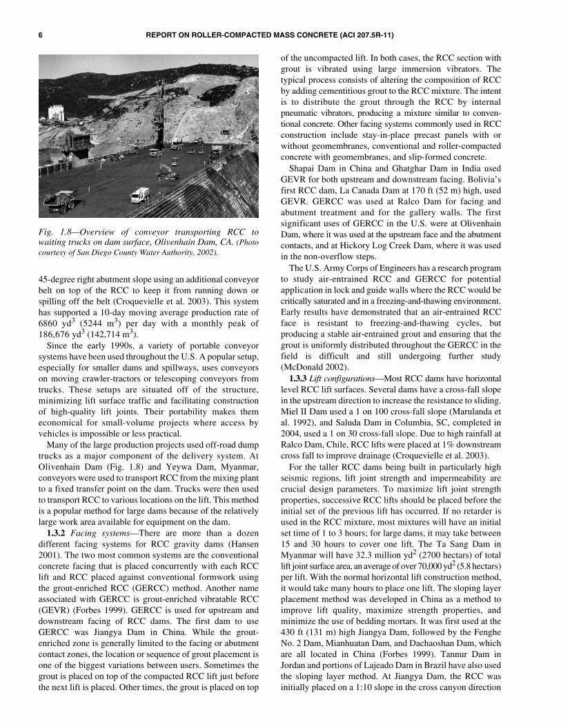
Many of the large production projects used off-road dumptrucks as a major component of the delivery system. AtOlivenhain Dam (Fig. 1.8) and Yeywa Dam, Myanmar,conveyors were used to transport RCC from the mixing plantto a fixed transfer point on the dam. Trucks were then usedto transport RCC to various locations on the lift. This methodis a popular method for large dams because of the relativelylarge work area available for equipment on the dam.
1.3.2 Facing systems—There are more than a dozendifferent facing systems for RCC gravity dams (Hansen2001). The two most common systems are the conventionalconcrete facing that is placed concurrently with each RCClift and RCC placed against conventional formwork usingthe grout-enriched RCC (GERCC) method. Another nameassociated with GERCC is grout-enriched vibratable RCC(GEVR) (Forbes 1999). GERCC is used for upstream anddownstream facing of RCC dams. The first dam to useGERCC was Jiangya Dam in China. While the grout-enriched zone is generally limited to the facing or abutmentcontact zones, the location or sequence of grout placement isone of the biggest variations between users. Sometimes thegrout is placed on top of the compacted RCC lift just beforethe next lift is placed. Other times, the grout is placed on top
of the uncompacted lift. In both cases, the RCC section withgrout is vibrated using large immersion vibrators. Thetypical process consists of altering the composition of RCCby adding cementitious grout to the RCC mixture. The intentis to distribute the grout through the RCC by internalpneumatic vibrators, producing a mixture similar to conven-tional concrete. Other facing systems commonly used in RCCconstruction include stay-in-place precast panels with orwithout geomembranes, conventional and roller-compactedconcrete with geomembranes, and slip-formed concrete.
Shapai Dam in China and Ghatghar Dam in India usedGEVR for both upstream and downstream facing. Bolivia’sfirst RCC dam, La Canada Dam at 170 ft (52 m) high, usedGEVR. GERCC was used at Ralco Dam for facing andabutment treatment and for the gallery walls. The firstsignificant uses of GERCC in the U.S. were at OlivenhainDam, where it was used at the upstream face and the abutmentcontacts, and at Hickory Log Creek Dam, where it was usedin the non-overflow steps.
The U.S. Army Corps of Engineers has a research programto study air-entrained RCC and GERCC for potentialapplication in lock and guide walls where the RCC would becritically saturated and in a freezing-and-thawing environment.Early results have demonstrated that an air-entrained RCCface is resistant to freezing-and-thawing cycles, butproducing a stable air-entrained grout and ensuring that thegrout is uniformly distributed throughout the GERCC in thefield is difficult and still undergoing further study(McDonald 2002).
1.3.3 Lift configurations—Most RCC dams have horizontallevel RCC lift surfaces. Several dams have a cross-fall slopein the upstream direction to increase the resistance to sliding.Miel II Dam used a 1 on 100 cross-fall slope (Marulanda etal. 1992), and Saluda Dam in Columbia, SC, completed in2004, used a 1 on 30 cross-fall slope. Due to high rainfall atRalco Dam, Chile, RCC lifts were placed at 1% downstreamcross fall to improve drainage (Croquevielle et al. 2003).
For the taller RCC dams being built in particularly highseismic regions, lift joint strength and impermeability arecrucial design parameters. To maximize lift joint strengthproperties, successive RCC lifts should be placed before theinitial set of the previous lift has occurred. If no retarder isused in the RCC mixture, most mixtures will have an initialset time of 1 to 3 hours; for large dams, it may take between15 and 30 hours to cover one lift. The Ta Sang Dam inMyanmar will have 32.3 million yd2 (2700 hectars) of totallift joint surface area, an average of over 70,000 yd2 (5.8 hectars)per lift. With the normal horizontal lift construction method,it would take many hours to place one lift. The sloping layerplacement method was developed in China as a method toimprove lift quality, maximize strength properties, andminimize the use of bedding mortars. It was first used at the430 ft (131 m) high Jiangya Dam, followed by the FengheNo. 2 Dam, Mianhuatan Dam, and Dachaoshan Dam, whichare all located in China (Forbes 1999). Tannur Dam inJordan and portions of Lajeado Dam in Brazil have also usedthe sloping layer method. At Jiangya Dam, the RCC wasinitially placed on a 1:10 slope in the cross canyon direction
Fig. 1.8—Overview of conveyor transporting RCC towaiting trucks on dam surface, Olivenhain Dam, CA. (Photocourtesy of San Diego County Water Authority, 2002).
REPORT ON ROLLER-COMPACTED MASS CONCRETE (ACI 207.5R-11) 7
to an eventual height of 10 ft (3 m). This process proceededacross the entire length of the dam until the dam was broughtup by 10 ft (3 m). The process was again repeated for another10 ft (3 m). The contractor eventually changed to a 1:20 slope.
The first application for the sloping layer method in the U.S.was at Table Rock Dam in Missouri, where RCC was placed tosupport a large gated conventional concrete spillway.
1.3.4 Design sections—The vast majority of RCC gravitydams have vertical upstream faces and sloping downstreamfaces. The downstream slopes have ranged from 1H:1V to0.8H:1V, with a few exceptions. Upper Stillwater Dam has acompound downstream slope. The lower two-thirds of theface was at a 0.6H:1V, and the upper section was at 0.32H:1V.At Olivenhain Dam, the slope was placed at a 0.8H:1V, buttransitioned on a 232 ft (70 m) radius to near vertical on theupper quarter of the slope. The radius concept was used toreduce any stress concentrations at an abrupt change insection slope.
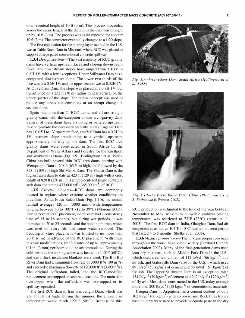
Spain has more than 24 RCC dams, and all are straightgravity dams with the exception of one arch-gravity dam.Several of these dams have a sloping or battered upstreamface to provide the necessary stability. Santa Eugenia Damhas a 0.05H to 1V upstream face, and Val Dam has a 0.2H to1V upstream slope transitioning to a vertical upstreamapproximately halfway up the dam. The first RCC archgravity dams were constructed in South Africa by theDepartment of Water Affairs and Forestry for the Knellportand Wolwedans Dams (Fig. 1.9) (Hollingworth et al. 1988).China has built several thin RCC arch dams, starting withWenquanpu Dam at 208 ft (63.5 m) high, and followed by the358 ft (109 m) high Shi Menzi Dam. The Shapai Dam is thehighest arch dam to date at 423 ft (129 m) high with a crestlength of 820 ft (250 m). It is a three-centered single curvaturearch dam containing 477,000 yd3 (365,000 m3) of RCC.
1.3.5 Extreme climates—RCC dams are commonlylocated in regions where extreme weather conditions areprevalent. At La Presa Ralco Dam (Fig. 1.10), the annualrainfall averages 120 in. (3000 mm), with temperaturesranging between 50 to 100°F (12 to 39°C) (Moreno 2003).During normal RCC placement, the mixture had a consistencytime of 15 to 18 seconds, but during wet periods, it wasincreased to 20 to 25 seconds, and the bedding mortar, whichwas used on every lift, had some water removed. Thebedding mixture placement was limited to no more than20 ft (6 m) in advance of the RCC placement. With thesemixture modifications, rainfall rates of up to approximately0.1 in. (3 mm) per hour could be accommodated. During thecold periods, the mixing water was heated to 140°F (60°C),and extra thick insulation blankets were used. The Bio BioRiver Dam had a minimum flow rate of 3000 ft3/s (90 m3/s)and a recorded maximum flow rate of 120,000 ft3/s (3390 m3/s).The original cofferdam failed, and the RCC-modifiedreplacement overtopped on several occasions. The main damovertopped when the cofferdam was overtopped or itsspillway operated.
The first RCC dam in Iran was Jahgin Dam, which was256 ft (78 m) high. During the summer, the ambient airtemperature would reach 122°F (50°C). Because of this,
RCC production was limited to the time of the year betweenNovember to May. Maximum allowable ambient placingtemperature was restricted to 73°F (23°C) (Azari et al.2003). The first RCC dam in India, Ghatghar Dam, had airtemperatures as hot as 104°F (40°C) and a monsoon periodthat lasted 4 to 5 months (Shelke et al. 2006).
1.3.6 Mixture proportions—The mixture proportions usedthroughout the world have varied widely (Portland CementAssociation 2002). Many of the first-generation dams usedlean dry mixtures, such as Middle Fork Dam in the U.S.,which used a cement content of 112 lb/yd3 (66 kg/m3) andno ash, and Galesville Dam (also in the U.S.), which used89 lb/yd3 (53 kg/m3) of cement and 86 lb/yd3 (51 kg/m3) offly ash. The Upper Stillwater Dam is an exception, with134 lb/yd3 (79 kg/m3) of cement and 292 lb/yd3 (172 kg/m3)of fly ash. Most dams constructed in the U.S. today averagemore than 200 lb/yd3 (118 kg/m3) of cementitious materials.
Urugua Dam in Argentina has a cement content of only102 lb/yd3 (60 kg/m3) with no pozzolans. Rock fines from abasalt quarry were used to provide adequate paste in the dry
Fig. 1.9—Wolwedans Dam, South Africa (Hollingworth etal. 1988).
Fig. 1.10—Le Presa Ralco Dam, Chile. (Photo courtesy ofB. Forbes and E. Warren, 2003).

8 REPORT ON ROLLER-COMPACTED MASS CONCRETE (ACI 207.5R-11)
consistency mixture. The trend in Spain is the use of highpaste mixtures of 250 lb/yd3 (150 kg/m3) cementitiousmaterials, with fly ash making up to 70% of the cementitiousmaterials. In Brazil, fly ash is not readily available, so stonedust or crushed powder is used as a filler. Some of thesefillers have shown pozzolanic properties. In Jordan, threeRCC dams were designed during the same period, withTannur Dam having a high paste, Wala Dam having amedium paste, and Mujib Dam having a lean consistency.
1.4—Advantages and disadvantagesThe advantages in RCC dam construction are extensive,
but there are also some disadvantages that should berecognized. Some of the advantages are primarily realizedwith certain types of mixtures, structural designs, productionmethods, weather, or other conditions. Likewise, somedisadvantages apply only to particular site conditions anddesigns. Each RCC project should be thoroughly evaluatedbased on technical merit and cost.
The main advantages are reduced cost, time of construction,and lower spillway costs. Another advantage of RCC damsis that the technology can be implemented rapidly. Foremergency projects such as the Kerrville Ponding Dam,RCC was used to rapidly build a new dam downstream of anembankment dam that was in imminent danger of failure dueto overtopping (Engineering News Record 1986). RCC wasalso used to quickly construct Concepcion Dam in Hondurasafter declaration of a national water supply emergency(Giovagnoli et al. 1991). Following the devastating fires atLos Alamos, NM, Pajarito Dam was built as a design/buildproject. This 130 ft (40 m) high dam was designed andconstructed in less than 6 months. When compared withembankment-type dams, RCC usually gains an advantagewhen spillway and river diversion requirements are large,where suitable foundation rock is close to the surface, andwhen suitable aggregates are available near the site. Anotheradvantage is reduced cofferdam requirements because, oncestarted, an RCC dam can be overtopped with minimalimpact, and the height of the RCC dam can quickly exceedthe height of the cofferdam. The 4th Street RCC dam in Fort
Worth, TX, replaced an earth dam that overtopped twice andfailed each time during construction before a concrete shellcould be completed. Following the second failure, an RCCgravity dam was constructed. During the 16 days of RCCplacement, the project was overtopped during a flash flood,but sustained no damage or construction delay. Other projectsthat overtopped during construction include Big HaynesDam and Tie Hack Dam in the U.S. and Le Presa Ralco Damin Chile (Fig. 1.11).
Although it is almost routine for efficiently designed RCCdams to be the least costly alternative when compared withother types of dams, there are conditions that may make RCCmore costly. RCC may not be appropriate when aggregatematerial is not reasonably available, the foundation rock is ofpoor quality or not close to the surface, or where foundationconditions can lead to excessive differential settlement.Sometimes it is difficult for an RCC dam to compete with anearthfill dam unless the dam is on a large drainage basin. Forlarge inflows, many earthfill dams require a separate largereinforced conventional concrete spillway that can cost morethan the dam itself. In these situations, RCC dams can becompetitive because flows can then be passed over the damin a spillway section.
1.5—Performance of RCC damsBecause RCC technology is relatively new and documentation
of structural performance is not readily available, theperformance record for RCC dams is somewhat limited. Therapid acceptance of this approach to dam construction,however, has resulted in many completed projects with avast range of details, sizes, and locations. This allows bothgeneralized and detailed comments to be made aboutperformance to date.
Performance involves design and construction in addition tostrength and operation of the completed structure. CompletedRCC dams are performing their intended purpose quite well.Each type of RCC material and design tends to have advantagesand disadvantages, and performs better in some areas than inothers. This includes seepage, in-place strength, and propertiesincluding lift joints, cracking, and durability.
In 1988, there were eight RCC dams in the U.S., one inBrazil, and one in Australia; other RCC dams were beingcompleted or put into operation. At that time, any RCC damhad been in operation a maximum of only 5 years, with mostof the dams having been just recently completed. The majorperformance aspects of each project, including cost,schedule, strength, thermal stress and cracking, and seepagewere reported (ASCE 1988).
Only 15 years later, there were more than 250 completedRCC dams in approximately 39 countries. There are manytypes of RCC, many approaches to design, and many waysto detail various aspects of the work. No single approach isbest for all situations. Each project should be evaluated todetermine the best options and overall approach. Data areneeded to evaluate the overall performance of RCC dams indifferent environments. Important data need to include liftline bonding properties, seepage and the performance ofvarious facing methods, long-term strength performance,
Fig. 1.11—Le Presa Ralco Dam, Chile, overtopping duringconstruction. (Photo courtesy of B. Forbes and E. Warren, 2003).

REPORT ON ROLLER-COMPACTED MASS CONCRETE (ACI 207.5R-11) 9
dynamic properties and performance under seismic loadings,durability in freezing-and-thawing environments, and theoverall structural performance of high RCC dams.
CHAPTER 2—NOTATION AND DEFINITIONS2.1—NotationA = area of cross sectionc = unit cohesionN = component of confining force normal to the sliding
surfaceT = driving force parallel to the sliding surfaceU = uplift force acting on cross sectionφ = angle of sliding friction
2.2—Definitionsconcrete, roller-compacted—concrete compacted by
roller compaction; concrete that, in its unhardened state, willsupport a roller while being compacted.
dam, arch—a structure resisting the pressure ofimpounded water by an arch principle, especially a damhaving in plan the form of a single arch abutted by naturalrock formations.
dam, gravity—a structure resisting the pressure ofimpounded water through its own weight.
gallery—a tunnel constructed through a dam used forconstruction access, drainage systems, and inspection activities.
grout-enriched roller-compacted concrete (GERCC)—RCC that is enriched by adding a fluid grout of cement andwater to the uncompacted RCC and consolidated withimmersion vibrators (also referred to as grout-enrichedvibrated roller-compacted concrete).
joint, lift—interface between two successive lifts.
CHAPTER 3—MATERIALS AND MIXTURE PROPORTIONING FOR ROLLER-COMPACTED
CONCRETE3.1—General
Mixture proportioning methods and objectives for RCCdiffer from those of conventional concrete. RCC shouldmaintain a consistency that will support a vibratory roller andhaul vehicles, and also be suitable for compaction by a vibratoryroller or other external methods. The aggregate grading andpaste content are critical parts of mixture proportioning.Specific testing procedures and evaluation methods have beendeveloped that are unique to RCC technology.
This chapter contains discussion of materials selectioncriteria and considerations in determining the method ofmixture proportioning for mass RCC placements. It presentsseveral alternative methods of mixture proportioning andcontains references to various projects. Requirements areusually site-specific, considering the performance criteria ofthe structure and are based on the designer’s approach,design criteria, and desired degree of product control.Regardless of the material specifications selected ormixture-proportioning method, the testing and evaluation oflaboratory trial batches are essential to verify the fresh andhardened properties of the concrete.
The cementitious material content for RCC dams hasvaried over a broad range, from 100 lb/yd3 (59 kg/m3) to
more than 500 lb/yd3 (297 kg/m3). At one end of the spectrum,the 3 in. (75 mm) nominal maximum size aggregate (NMSA)interior mixture at Willow Creek Dam contained 112 lb/yd3
(60.5 kg/m3) of cementitious material. The mixture, whichcontained 80 lb/yd3 (47.5 kg/m3) of cement plus 32 lb/yd3
(19.0 kg/m3) of fly ash, averaged 2620 psi (18.2 MPa)compressive strength at 1 year (USACE 1984). In compar-ison, the 2 in. (50 mm) NMSA interior mixture at UpperStillwater Dam contained 424 lb/yd3 (251.6 kg/m3) ofcementitious material, consisting of 134 lb/yd3 (79.5 kg/m3)of cement plus 290 lb/yd3 (172.0 kg/m3) of fly ash, andaveraged 6170 psi (42.6 MPa) at 1 year (Crow et al. 1984).Many RCC projects have used a cementitious materialscontent between 175 and 300 lb/yd3 (105 and 180 kg/m3)and produced an average compressive strength between2000 to 3000 psi (14 and 21 MPa) at an age of 90 days to 1 year.Mixture proportions for some dams are presented in Table 3.1.
An essential element in the proportioning of RCC fordams is the volume of paste. The paste volume should fill ornearly fill aggregate voids and produce a compactible, denseconcrete mixture. The paste volume should also be sufficientto produce bond and watertightness at the horizontal liftjoints when the mixture is placed and compacted quickly ona reasonably fresh joint. Mixtures containing a low quantityof cementitious materials may require added quantities ofnonplastic fines to supplement the paste fraction in fillingaggregate voids.
Certain economic benefits can be achieved by reducingthe processing requirements on aggregates; the normal sizeseparations; and the separate handling, stockpiling, andbatching of each size range. The designer, however, shouldrecognize that reducing or changing the normal requirementsfor concrete aggregates should be weighed against greatervariation in the properties of the RCC that is produced, andshould be accounted for by a more conservative RCCdesign assumption.
3.2—MaterialsA wide range of materials have been used in the production
of RCC. Much of the guidance on materials provided in ACI207.1R may be applied to RCC. The material constraints ofgravity RCC structures are often less demanding; thus, othermaterials quality options and subsequent performancecharacteristics are possible. The designer, as always, shouldevaluate the actual materials for the specific project and theproportions under consideration, design the structure accord-ingly, and provide appropriate construction specifications.
3.2.1 Cementitious materials3.2.1.1 Portland cement—RCC can be made with any of
the basic types of portland cement such as found in ASTMC150/C150M, C595/C595M, C1157/C1157M, and applicableAASHTO standards, or other international standards. ASTMC150/C150M cements are specified by both chemical andphysical requirements. For mass applications, cements witha lower heat generation are desirable to control or reducethermal cracking. Lower heat generation is achievedprimarily by decreasing the percentage of tricalcium aluminate(C3A) and the ratio of tricalcium silicate to dicalcium silicate

10 REPORT ON ROLLER-COMPACTED MASS CONCRETE (ACI 207.5R-11)
(C3S to C2S). Higher heat generation may require decreasedjoint spacing for crack control. ASTM C150/C150M cementwith optional heat-of-hydration limits, Type V (sulfate-resis-tant), and ASTM C595/C595M Type IP (portland-pozzolancement) and Type IS (portland blast-furnace slag cement)can decrease heat generation. Strength development forthese cements is usually slower than for the standard Type I(general use) cement at early ages, but higher strengths thanRCC produced with Type I cement are ultimately produced.
Heat generation due to hydration of the cement is typicallycontrolled by use of lower heat-of-hydration cements, use ofless cement, and replacement of a portion of the cement withpozzolan or a combination of these. Reduction of peakconcrete temperature may be achieved by other methods,such as reduced placement temperatures. The selection ofcement type should consider economics of cement procurement.For small- and medium-sized projects, it may not be costeffective to specify a low-heat cement that is not locallyavailable. The availability of cement types varies regionallyand over time. Manufacturers in the U.S. are producingfewer cement types (less specialty types such as Type IV andType V) than in the past. Consequently, the selection ofcement type for mass concrete placements needs to bethoroughly researched and confirmed before selectingcement for a laboratory mixture proportioning program andspecifying for a project. Due to the high production capability
of RCC, special attention may be required to ensure acontinuous supply of cement to the project.
3.2.1.2 Pozzolans—The selection of a pozzolan suitablefor RCC should be based on its conformance with ASTMC618. Pozzolans meeting the specifications of ASTM C618for Class C, Class F, and Class N have been successfullyused in RCC mixtures. Class F and Class N pozzolans arepreferred because they normally contribute less heat ofhydration than Class C and have greater sulfate resistance.For Class C pozzolans, more attention may be needed withregard to set time, sulfate resistance, and free lime content. Theuse of pozzolan will depend on required material performanceas well as on its cost and availability at each project.
Pozzolan in RCC mixtures may serve one or more of thefollowing purposes: 1) as a partial replacement for cement toreduce heat generation; 2) as a partial replacement forcement to reduce cost; and 3) as an additive to providesupplemental fines for mixture workability and pastevolume. The rate of cement replacement may vary from noneto 80% by mass. RCC mixtures with a high cementitiousmaterial content often use larger amounts of pozzolan toreplace portland cement to reduce the internal temperaturerise that would otherwise be generated and consequentlyreduce thermal stresses.
In RCC mixtures with a low cement content, pozzolanshave been used to ensure an adequate amount of paste for
Table 3.1—Mixture proportions of some roller-compacted concrete (RCC) dams
Dam/project
Mixture type/ID Year
NMSA,in. (mm)
Air, %
Water Cement PozzolanFine
aggregateCoarse
aggregateDensity, lb/
yd3 (kg/m3)
Air-entrained admixture,
oz/yd3 (cc/m3)
Water-reducing admixture,
oz/yd3 (cc/m3)Quantities, lb/yd3 (kg/m3)
Al Wehdah 70C60F 2006 2.0 (50) 2.0 211 (25) 118 (70) 101 (60) 1530 (910) 2300 (1365) 4260 (2530) 22 (13) —
Al Wehdah 60C60F 2006 2.0 (50) 2.0 211 (25) 101 (60) 101 (60) 1530 (910) 2310 (1370) 4255 (2525) 22 (13) —
Camp Dyer RCC1 1994 1.5 (37.5) 3.6 151 (90) 139 (82) 137 (81) 1264 (750) 2265 (1344) 3956 (2347) 7 (4) 4 (2)
Concepcion 152C 1990 3 (75) 0.5 157 (93) 152 (90) 0 1371 (813) 2057 (1220) 3737 (2217) — —
Cuchillo Negro 130C100P 1991 3 (75) — 228 (135) 130 (77) 100 (59) 1591 (944) 2045 (1213) 4094 (2429) — —
GalesvilleRCC1 1985 3 (75) — 190 (113) 89 (53) 86 (51) 1310 (777) 2560 (1519) 4235 (2513) — —
RCC2 1985 3 (75) — 190 (113) 110 (65) 115 (68) 1290 (765) 2520 (1495) 4225 (2513) — —
Middle Fork 112C 1984 3 (75) — 160 (95) 112 (66) 0 1152 (683) 2138 (1268) 3562 (2113) — —
Santa Cruz RCCAEA 1989 2 (50) 2.3 170 (101) 128 (76) 127 (75) 1227 (728) 2301 (1365) 3953 (2345) 7 (4) 3 (2)
Siegrist
80C80P 1992 1.5 (37.5) 1 162 (96) 80 (47) 80 (47) 1922 (1140) 2050 (1216) 4294 (2548) — —
90C70P 1992 1.5 (37.5) 1 162 (96) 90 (53) 70 (42) 1923 (1141) 2052 (1217) 4297 (2549) — —
100C70P 1992 1.5 (37.5) 1 162 (96) 100 (59) 70 (42) 1920 (1139) 2048 (1215) 4300 (2551) — —
Stacey Spillway 210C105P 1989 1.5 (37.5) — 259 (154) 210 (125) 105 (62) 3500 (2076) — — — —
Stagecoach 120C130P 1988 2 (50) — 233 (138) 120 (71) 130 (77) 156 (686) 2459 (1459) 4098 (2431) — —
UpperStillwater
RCCA85 1985 2 (50) 1.5 159 (94) 134 (79) 291 (173) 1228 (729) 2177 (1292) 3989 (2367) — 12 (7)
RCCB85 1985 2 (50) 1.5 150 (89) 159 (94) 349 (207) 1171 (695) 2178 (1292) 4007 (2377) — 20 (12)
RCCA 1986 2 (50) 1.5 167 (99) 134 (79) 292 (173) 1149 (682) 2218 (1316) 3960 (2349) — 16 (9)
RCCB 1986 2 (50) 1.5 168 (100) 157 (93) 347 (206) 1148 (682) 2131 (1264) 3952 (2345) — 21 (12)
Urugua-I 101C 1988 3 (75) — 169 (100) 101 (60) 0 2102 (1247) 2187 (1297) 4559 (2705) — —
Victoria 113C112P 1991 2 (50) — 180 (107) 113 (67) 112 (66) 1365 (810) 2537 (1505) 4307 (2555) — —
Willow Creek
175C 1982 3 (75) 1.2 185 (110) 175 (104) 0 1108 (657) 2794 (1958) 4262 (2529) — —
175C80P 1982 3 (75) 1.2 185 (110) 175 (104) 80 (47) 1097 (645) 2739 (1625) 4266 (2531) — —
80C32P 1982 3 (75) 1.2 180 (107) 80 (47) 32 (19) 1123 (666) 2833 (1681) 4248 (2520) — —
315C135P 1982 1.5 (37.5) 1.2 184 (109) 315 (187) 135 (80) 1390 (825) 2086 (1238) 4110 (2438) — —
Zintel Canyon
125CA 1992 2.5 (63) 4.5 170 (101) 125 (74) 0 1519 (901) 2288 (1357) 4102 (2434) 18 (11) 18 (11)
125CNA 1992 2.5 (63) 1.4 188 (112) 125 (74) 0 1586 (941) 2371 (1407) 4270 (2533) — 18 (11)
300CA 1992 2.5 (63) — 171 (101) 300 (178) 0 1348 (800) 2388 (1417) 4207 (2496) 36 (21) 42 (25)
REPORT ON ROLLER-COMPACTED MASS CONCRETE (ACI 207.5R-11) 11
filling aggregate voids and coating aggregate particles.While the pozzolan enhances the paste volume of thesemixtures, it may not enhance the long-term strengthdevelopment if the pozzolan has a low reactivity.
Class F pozzolan, especially at cool temperatures, generallydelays the initial set of RCC mixtures, contributing to lowearly strength but extending the working life of the freshlycompacted lift joint. In high pozzolan-content RCCmixtures, the beneficial reduction in early temperature risemay be partially offset by continued temperature rise after28 days. Mixtures with high pozzolan content can experienceconsiderable additional heat rise from 30 to 90 days afterplacement compared with 100% cement mixtures. The fine-ness and reactivity of Class F pozzolan is critical for strengthperformance. The 1-year compressive strength of high-pozzolan RCC mixtures at Upper Stillwater Dam decreased12% when the percentage retained on the No. 325 sieveincreased from approximately 24 to 38% (Dolen 2003). Theoptimum percentage of pozzolan should thus be determinedby testing with the job materials.
3.2.2 Aggregates3.2.2.1 General quality issues—The selection of
aggregates and the control of aggregate properties andgrading are important factors influencing the quality anduniformity of RCC production. Aggregates similar to thoseused in conventional concrete and aggregates that do notmeet the normal standards or requirements for conventionalconcrete have both been successfully used in RCC damconstruction (Gaekel and Schrader 1992). The use ofmanufactured coarse aggregate (crushed stone) has beenfound to reduce the tendency for segregation as comparedwith rounded gravels.
Marginal aggregates are those aggregates that do not meettraditional standards, such as ASTM C33/C33M. Limits onphysical requirements and on deleterious materials foraggregates to be used in RCC for a specific applicationshould be established before construction based on requiredconcrete performance and demonstrated field and laboratoryevaluations. The majority of RCC projects have beenconstructed with aggregates meeting all of the ASTM C33/C33M requirements, with the exception of an increasedamount of fines passing the No. 200 (75 μm) sieve. Themineralogy of fines (for example, fines from aggregates suchas limestone and granite) has a significant effect on waterdemand and workability of RCC. The allowable amount offines in RCC mixtures for mass placements should thereforebe determined based on the most readily available and mosteconomical aggregate that produces RCC meeting theproject structural requirements.
Aggregates of marginal quality have been used in RCC onsome projects because they were close to the site and therebythe most economical source available. The design of thestructure should accommodate any change in performancethat may result. On some projects, mixtures that usedaggregates of lower physical strength produced RCC withsatisfactory creep rates, elastic moduli, and tensile straincapacity. These properties are desirable for mass concreteapplications where lower concrete strength can be tolerated.
If practical, lower-quality aggregates are best used in theinterior of dams where they can be encapsulated by higher-quality concrete, especially in freezing-and-thawing areas.
RCC can provide a modulus of elasticity equal to orgreater than that of a conventional concrete of equalcompressive strength. For preliminary design studies,USACE ETL 110-2-343 (USACE 1993) recommendsassuming the modulus of elasticity to be equal to 57,000(fc′ )
1/2
increased by 15% for seismic load conditions and reduced by33% for long-term loading conditions where creep effectsare important. A basic objective in proportioning anyconcrete is to incorporate the maximum amount of aggregateand minimum amount of water into a workable mixture,thereby reducing the cementitious material quantity andreducing consequent volume change of the concrete. Thisobjective is accomplished by using a well-graded aggregatewith the largest maximum size that is practical for place-ment. The proper combination of materials should result in amixture that achieves the desired properties with adequatepaste and a minimum cementitious content. However, in RCCmixtures, the potential for segregation and the means ofcompaction should also be primary considerations in selectingthe maximum size of aggregate. Although early projects inthe U.S. used a 3 in. (75 mm) NMSA, a 2 in. (50 mm) NMSAor smaller is less prone to segregation and is becoming morewidely used.
The combined aggregate gradation should be selected tominimize segregation. The key to controlling segregationand providing a good compactible mixture is having agrading that is consistent and contains more material passingthe No. 4 (4.75 mm) sieve than typical in conventionalconcrete of similar NMSA. Table 3.2 provides typicalcombined aggregate grading for various projects.
In conventional concrete, the presence of any significantquantity of flat and elongated particles is usually undesirable.RCC mixtures, however, appear to be less affected by flatand elongated particles than conventional concrete mixturesbecause vibratory compaction provides more energy thantraditional consolidation. Field tests with 40% flat andelongated particles on any sieve and an average less than30%, as determined by ASTM D4791 with a ratio of 1:5,have had no significant problems. The U.S. Army Corps ofEngineers currently has a limit of 25% on the allowablecontent of flat and elongated particles in any size group(USACE 1994b).
3.2.2.2 Coarse aggregate—The selection of NMSAshould be based on the need to reduce cementitious materialrequirements, control segregation, economize aggregateproduction, and facilitate compaction. Most RCC projectshave used a NMSA of 1-1/2 to 3 in. (37.5 to 75 mm). TheU.S. Bureau of Reclamation presently limits the NMSA to 2 in.(50 mm) and requires a minimum of 50% crushed aggregatein mass RCC. There has typically not been enough materialcost savings from using aggregate sizes larger than 3 in.(75 mm) to offset the added batching cost and cost ofcontrolling the increased segregation problems associatedwith the larger aggregates. Coarse aggregate size has littleeffect on compaction when the thickness of the placement

12 REPORT ON ROLLER-COMPACTED MASS CONCRETE (ACI 207.5R-11)
layers is more than three times the NMSA, segregation isadequately controlled, and large vibratory rollers are used.
Grading of coarse aggregate usually follows ASTM C33/C33M size designations. Where close control of grading ofcoarse aggregate and RCC production are desired, size sepa-rations should follow normal concrete practice, as recom-mended in ACI 304R. Cost savings can be realized bycombining two or more size ranges such as ASTM C33/C33M size designations 357 or 467 for 2 in. to No. 4 (50 to4.75 mm) and 1-1/2 in. to No. 4 (37.5 to 4.75 mm), respec-tively. Note that as the size range increases, it becomesincreasingly difficult to avoid segregation of the larger particlesduring stockpiling and handling of this aggregate. Aggre-gates for RCC have been in a single stockpile or have beenseparated into as many as five aggregate sizes. Some projectssimply use a coarse-aggregate and a fine-aggregate stock-pile. Other projects have blended products from multiplestockpiles that are not strictly coarse and fine fractions. Pine-brook Dam in Colorado used two base gravel type grada-tions—one commercially produced and the other producedfrom site materials. More important than the stockpile splitis the resulting combined gradation and the ability toproduce a consistent, workable mixture that can be mixed,placed, and compacted. An advantage for coarse aggregateseparation arises for projects in hot climates or designsneeding precooled aggregates to meet temperature require-ments. Fine aggregates or aggregates with fine contents aredifficult to cool with chilled water or air-blast methods.
The design engineer should weigh the potential costsavings in a reduction in the number of stockpiles andseparate handling and weighing facilities against the potentialfor increased variation in aggregate grading and its impacton uniform placement and compaction.
RCC mixtures for overtopping protection for embankmentdams frequently use a NMSA of 1 in. (25 mm) because the
concrete section is less massive and there are normally nosignificant temperature concerns. Some designers have usedlocally available aggregate road base material with gradingrequirements similar to that contained in ASTM D2940/D2940M. Because the volume of concrete required isnormally not substantial, the RCC mixture can be obtainedfrom locally available commercial concrete suppliers.
3.2.2.3 Fine aggregate—The grading of fine aggregatestrongly influences paste requirements and compactibility ofRCC. It also affects water and cementitious materialrequirements needed to fill the aggregate voids and coat theaggregate particles.
For those mixtures with a sufficient cementitious materialscontent and paste volume, ASTM C33/C33M fine-aggregategrading can be used. ASTM graded fine aggregates arenecessary if an air-entraining admixture is used in RCC.
3.2.2.4 Fines—The primary role of supplemental fines(material passing the No. 200 [75 μm] sieve) is to lower thevolume of voids in fine aggregates without significantlyincreasing the water demand of the RCC mixture. In lowcementitious-materials or low paste-content mixtures, supple-mental fines are usually required to fill all the aggregatevoid spaces. Depending on the volume of cementitiousmaterial and the NMSA, the required total minus No. 200(75 μm) fines may be as much as 10% of the total aggregatemass, with most mixtures using approximately 3 to 8%.Characteristics of the fines and fines content will affect therelative compactibility of the RCC mixture, and can influencethe number of passes of a vibratory roller required for fullcompaction of a given layer thickness. Regardless ofwhether it is accomplished by adding aggregate fines,cement, pozzolan, or combination of these, most compactibleRCC mixtures contain approximately 8 to 12% total solidsfiner than the No. 200 (75 μm) sieve by volume, or 12 to 16%by mass. This is illustrated in Table 3.2. The fines fill
Table 3.2—Combined aggregate gradings for RCC from various projects in U.S.Sieve size Willow Creek Upper Stillwater Christian Siegrist Zintel Canyon Stagecoach Elk Creek
4 in. (100 mm) — — — — — —
3 in. (75 mm) 100 — — — — 100
2.5 in. (62 mm) — — — 100 — 96
2 in. (50 mm) 90 100 — 98 100 86
1.5 in. (37.5 mm) 80 95 100 91 95 76
1 in. (25 mm) 62 — 99 77 82 64
3/4 in. (19 mm) 54 66 91 70 69 58
3/8 in. (9.5 mm) 42 45 60 50 52 51
No. 4 (4.75 mm) 30 35 49 39 40 41
No. 8 (2.36 mm) 23 26 38 25 32 34
No. 16 (1.18 mm) 17 21 23 18 25 31
No. 30 (0.60 mm) 13 17 14 15 15 21
No. 50 (0.30 mm) 9 10 10 12 10 15
No. 100 (0.15 mm) 7 2 6 11 8 10
No. 200 (75 µm) 5 0 5 9 5 7
C + P, lb/yd3 (kg/m3) 80 + 32 (47 + 19) 134 + 291 (80 + 173) 100 + 70 (59 + 42) 125 + 0 (74 + 0) 120 + 130 (71 + 77) 118 + 56 (70 + 33)
Total fines*, % 20 21 19 21 — 21
Workability Poor Excellent Excellent Excellent Good Excellent*Total fines = all materials in full mixture with particle size smaller than No. 200 (75 µm) sieve.

REPORT ON ROLLER-COMPACTED MASS CONCRETE (ACI 207.5R-11) 13
aggregate void space, provide a compactible consistency,help control segregation, and decrease permeability. Includingaggregate fines in low cementitious-paste mixtures allowsreductions in the cementitious materials content, provided thatthey fill voids that would otherwise be filled with cementitiouspaste in the aggregates. Excessive additions of aggregate finesafter the aggregate voids are filled are harmful to the RCCmixture because of decreased workability, increased waterdemand, and subsequent strength loss.
When adding aggregate fines to a mixture, anotherconsideration is the nature of the fines. Crusher fines andsilty material are usually acceptable. Clay fines, which arealso called plastic fines, can cause an increase in waterdemand and a loss of strength, and produce a sticky mixturethat is difficult to mix, transport, and compact. Fines, especiallyclay fines, may coat the surfaces of coarse aggregates andreduce the paste-aggregate bond and reducing strengthpotential. This problem can be avoided by washing the coarseaggregates either during production or before batching.
3.2.3 Chemical admixtures—Chemical admixtures havebeen used in RCC mixtures to change the setting propertiesand, in some cases, to affect a change in water content. Theeffectiveness of chemical admixtures may depend on theworkability of the mixture, the aggregate gradation, and thetype of cementitious materials. Chemical admixtures in RCCare commonly used to retard the setting time to reduce coldjoints for improving bond between successive lifts (Wenquanet al. 1997). ASTM C494/C494M Types A (water-reducing)and D (water-reducing and retarding) are the mostcommonly used chemical admixtures. Water-reducingadmixtures, used at very high dosages, have been shown toreduce water demand, increase strength, retard set, andpromote workability in some RCC mixtures (Hopman andChambers 1988). As with conventional concrete, the presenceof minus No. 200 (75 μm) fines in many RCC mixtures canimpact the dosage rate required to be effective, particularlyif the fines content is high or if they include clay. Admixturesshould be evaluated with the actual RCC materials beforebeing used in the field.
Air-entraining admixtures are not commonly used in RCCmixtures because of the difficulty in generating the voids ofthe proper size and distribution when the mixture has a no-slump consistency. Air-entrained RCC has been used on aproduction basis in China and the U.S. The freezing-and-thawing resistance of RCC is improved with entrained air(Dolen 1991). To entrain air in RCC, however, a Vebeconsistency less than approximately 20 seconds is generallynecessary, and the aggregates should be free from excessivefines. The dosage of air-entraining admixture has rangedfrom the normal manufacturers’ dosage for clean aggregatesto higher than normal for other mixtures.
Entrained air has an additional benefit as a means ofimproving the workability of the RCC, decreasing the pastevolume, and decreasing the Vebe consistency. The totalwater content of air-entrained RCC can be reduced as muchas 12% compared with the same non-air-entrained mixture(Dolen 2002).
In some instances, caution is necessary to avoid reducing thepaste volume of air-entrained RCC to less than the minimumnecessary to fill aggregate voids without air (refer to Table 3.2).This can cause segregation and difficulties in achievingcomplete compaction if the air is lost.
The costs of admixtures in RCC include the costs of theadmixtures, the batching equipment costs, and the additionalcost for quality-control testing. The dosage is normally bymass of cementitious materials, or sometimes by cementonly. Unless an unusually high dosage is necessary, the costof admixtures is similar or less than conventional concretedue to the low cementitious materials content of many RCCmixtures. The cost of batching admixtures ranges from nosubstantial cost for conventional batching plants to the costof adding batching devices for continuous batching plants.To control air-entrained RCC, inspectors should perform thenecessary air content tests and be able to discern if changesin density in the field (through nuclear density testing) arethe result of changes in air content or changes in compaction.
3.3—Mixture proportioning considerationsOptimum RCC proportions consist of a balance between
good material properties and acceptable workability for theplacement methods. This includes minimizing segregation.In implementing a specific mixture-proportioning procedure,the following considerations regarding plastic and hardenedproperties should be addressed.
3.3.1 Workability—Sufficient workability is necessary toachieve compaction or consolidation of the mixture.Sufficient workability is also necessary to provide anacceptable appearance when RCC is to be compactedagainst forms. Workability is most affected by the pasteportion of the mixture that includes cement, pozzolan,aggregate fines, water, and air. When there is sufficient pasteto fill aggregate voids, workability of RCC mixtures isnormally measured on a vibratory table with a Vebe apparatus(Fig. 3.1) in accordance with ASTM C1170. This testproduces a Vebe time for the specific mixture and is usedsimilar to the slump test for conventional concrete. RCCmixtures with Vebe consistency of 10 to 45 seconds have aworkability sufficient for ease of compaction, uniformdensity from top to bottom of the lift, bonding with previouslyplaced lifts, and for support of compaction equipment. RCCmixtures, however, have been proportioned with a widerange of workability levels. One test method used forcompaction control in earthwork, the modified Proctor test(ASTM D1557), tests a wide range of compaction character-istics and provides an indication of workability for a specificmaterial. The modified Proctor test varies the moisturecontent of a mixture over a wide range, from extremely dry(Vebe less than 30 seconds) or drier (Vebe greater than 30seconds). The modified Proctor test is used in earthworkprojects to determine an optimum moisture and maximumdry density that is suitable for vibratory compaction, typicallywith 6 to 9 in. (150 to 230 mm) compacted lift thickness. SomeRCC mixtures have contained such low paste volumes thatworkability could not be measured by the Vebe apparatus.This is particularly true of those mixtures proportioned with

14 REPORT ON ROLLER-COMPACTED MASS CONCRETE (ACI 207.5R-11)
very low cementitious materials contents or designed moreas cement stabilized fills. Workability of these types ofmixtures needs to be judged by observations during placementand compaction, and by compacted density and moisturecontent measurements.
The water demand for a specific level of workability willbe influenced by the size, shape, texture, and gradation ofaggregates and the volume and nature of cementitious andfine materials. Depending on the paste volume, waterdemand can be established by Vebe time or by the moisture-density relationship, discussed in a following section.
3.3.2 Strength—RCC strength depends on the quality andgrading of the aggregate, mixture proportions, and thedegree of compaction. There are differing basic strengthrelationships for RCC, depending on whether the aggregatevoids are completely filled with paste or not. The water-cement ratio (w/c) law, as developed by Abrams (1918), isonly valid for fully consolidated concrete mixtures. There-fore, the compressive strength of RCC is a function of thewater-cementitious material ratio (w/cm) only for fullycompacted mixtures, with a measurable Vebe consistencyusually in the 15- to 45-second range. Figure 3.2 shows thisgeneral relationship. For drier-consistency (all voids notfilled with paste) mixtures, compressive strength iscontrolled by moisture-density relationships. With the sameaggregate, the moisture content necessary to producemaximum dry density is less than the moisture required toproduce an RCC mixture with a Vebe time in the range of15 seconds. In general, the optimum moisture content doesnot vary significantly (on the order of 0.5 to 1%) for a widerange of cementitious contents.
Mixtures that contain less-than-optimum moisture areusually poorly compacted, with a resulting loss in densityand strength. In this case, the addition of water to the mixtureproduces higher compressive strength by increasing thepaste volume and filling voids. For fully consolidatedmixtures exceeding optimum moisture, slight decreases in
moisture content tend to produce a higher compressivestrength. The design strength is usually not determined bythe compressive stresses in the structure, but is moredependent on the required tensile strength, shear strength,and durability, particularly along lift surfaces. These areusually dictated by dynamic and static structural analyses,combined with an analysis of thermal stresses. Compressivestrength is generally regarded as the most convenient indicatorof the quality and uniformity of the concrete. Therefore, thedesign compressive strength is usually selected based on thelevel of strength necessary to satisfy compressive, tensile, andshear stresses plus durability under all loading conditions.
RCC mixtures should be proportioned to produce thedesign compressive strength plus an overdesign factor basedon expected strength variation. Statistical concepts, aspresented in ACI 214R, can be used for this purpose. Forexample, if the design strength is 2500 psi (17.2 MPa) at1 year, and the expected standard deviation is 600 psi (4.1 MPa)with no more than two in 10 tests allowed below the designstrength, the required average strength would be equal to thedesign strength plus 500 or 3000 psi (3.5 or 20.7 MPa). TheRCC mixture should then be proportioned for a 3000 psi(20.7 MPa) strength at 1 year. Similar to conventionalconcrete, a lower standard deviation will permit a reductionin required average strength. The cost of controlling strengthvariation should be balanced against project needs and thesavings that may be realized.
Compressive strength of RCC is usually determined on 6x 12 in. (150 x 300 mm) cylindrical specimens. Specimenscan be prepared using a vibrating table, as described inASTM C1176/C1176M for more workable mixtures, or canbe compacted by a tamping/vibrating hammer, as describedin ASTM C1435/C1435M for a wide range of materials,workability, and paste volumes, including drier consistencymixtures. Cylinder molds should be steel or supported by asteel sleeve if plastic or sheet metal cylinder molds are used.
Fig. 3.1—ASTM C1170 Vebe consistency test apparatuswith 27.5 lb (12 kg) surcharge. (Photo courtesy of U.S.Department of Agriculture, National Resources ConservationService, 2008.)
Fig. 3.2—General relationship between compressivestrength and w/cm.

REPORT ON ROLLER-COMPACTED MASS CONCRETE (ACI 207.5R-11) 15
These methods use the fraction of the RCC mixture thatpasses the 2 in. (50 mm) sieve.
3.3.3 Segregation—A major goal in the proportioning ofRCC mixtures is to produce a cohesive mixture whileminimizing the tendency to segregate during transporting,placing, and spreading. Well-graded aggregates with aslightly higher fine aggregate content than conventionalconcrete are essential. If not proportioned properly, RCCmixtures tend to segregate more because of the low pastevolume of the mixture. This is controlled by aggregate grading,moisture content, and adjustment of fine content in lowercementitious-content mixtures. Higher paste-content mixturesare usually more cohesive and less likely to segregate.
3.3.4 Permeability—Mixtures that have a paste plus finesvolume of 18 to 22% by mass will provide a suitable level ofimpermeability that is similar to conventional mass concretein the unjointed mass of the RCC. Most concerns regardingRCC permeability are directed at lift-joint seepage. Highercementitious-content or high-workability mixtures that bondwell to fresh lift joints will produce adequate watertightness.Lower-cementitious-content or low-workability mixturesare not likely to produce adequate watertightness withoutspecial treatment, such as use of bedding mortar betweenlifts. Where a seepage cutoff system is used on the upstreamface, the permeability of the RCC may be of little significanceexcept as it may relate to freezing-and-thawing resistance ofexposed surfaces.
3.3.5 Heat generation—RCC mixture proportioning formassive structures should consider the heat generation of thecementitious materials. To minimize the heat of hydration,care should be taken in the selection and combination ofcementing materials used. In cases where pozzolan is used,it is worthwhile to conduct heat-of-hydration testing onvarious percentages of cement and pozzolan to identify thecombination that generates the minimum heat of hydrationwhile providing satisfactory strength. The amount ofcementitious material used in the mixture should be no morethan is necessary to achieve the level of strength needed.Proportioning should incorporate those measures thatnormally minimize the required content of cementitiousmaterial, such as appropriate NMSA and well-gradedaggregates. Further guidance in controlling heat generationcan be found in ACI 207.1R, 207.2R, and 207.4R.
3.3.6 Durability—The RCC mixture should provide therequired degree of durability based on materials used,exposure conditions, and expected level of performance.RCC should be free of damaging effects of alkali-aggregatereactivity by proper evaluation and selection of materials.Recent work indicates that some air-entrained RCC can beproduced with adequate freezing-and-thawing resistance(McDonald 2002). If air entrainment cannot be achieved andthe RCC is exposed, consideration should be given toincreasing the strength for improved durability. RCCsurfaces exposed to flowing water performed well whereexposure has been of short duration and intermittent.Freezing-and-thawing resistance and erosion should not be amajor concern during mixture proportioning if it will beprotected with conventional concrete. The durability of RCC
can be significantly reduced if the mixture is not fullycompacted. Though this is partially a construction controlproblem, a mixture proportioned with a paste volumesufficient for compaction can greatly improve its durability.
3.3.7 Construction conditions—Construction requirementsand equipment should be considered during mixtureproportioning. Some construction methods, placementschedules, and equipment selections are less damaging tocompacted RCC than others. A higher workability mixturemay result in a compacted RCC surface that tends to rut fromhauling trucks and rollers. Wheeled traffic may producesevere rutting and should be restricted from operating on thecompacted surface of the last lift of the day before it reachesfinal set. Rutting of the lift surface at Elk Creek Dam and UpperStillwater Dam was observed to exceed 3 in. (75 mm). Severerutting is generally not desirable because ruts inhibit jointcleanup and treatment. Timely finish rolling helps recompactthe ruts after the end of the placement. Placing conditions withmany obstacles that require smaller compaction equipmentbenefit from mixtures having a higher level of workability.
3.4—Mixture proportioning methods3.4.1 General—A number of mixture proportioning
methods have been successfully used for RCC structuresthroughout the world. These methods have differedsignificantly due to the location and design requirements ofthe structure, availability of materials, the mixing andplacing equipment used, and time constraints. Most mixture-proportioning methods are variations of two generalapproaches: 1) a w/cm approach with the mixture proportionsdetermined by solid volume; and 2) a cemented-aggregate orsoils approach with mixture proportions determined byeither solid volume or moisture-density relationship. Bothapproaches are intended to produce quality concrete suitablefor roller compaction and mass concrete construction. Thebasic concepts behind these approaches are covered in ACI211.3R, Appendix 3. Mixture proportions used for someRCC dams are shown in Table 3.1.
RCC mixture proportions can follow the convention usedin traditional concrete practice where the mass of eachingredient contained in a compacted unit volume of themixture is based on saturated surface-dry (SSD) aggregatecondition. A practical reason for use of this standard conventionis that concrete properties are the primary control parametersand, hence, conventional concrete practice should reduce thepotential for miscommunication. For example, RCC mixingusing conventional concrete plants require that mixtureconstituents be identified based on SSD aggregate conditionsfor input to the plant control system. This is not necessarilythe case for continuous mixing plants, however. Mixtureproportions may have to be converted to percent by dryweight of aggregate for RCC mixing in continuous mixingplants. Another reason supporting the concrete approach isthat the RCC is typically placed and measured to specifiedlines, grades, and dimensions. The concrete proportioningmethod provides a means for establishing if the mixture isyielding properly (batched volume corresponds correctly toplaced volume once compaction is factored); this is much

16 REPORT ON ROLLER-COMPACTED MASS CONCRETE (ACI 207.5R-11)
more difficult with a soils approach maximum densitymethod discussed in Section 3.4.5.
3.4.2 USACE method—This proportioning method isbased on w/cm and strength relationships and is very similarto proportioning conventional concrete mixtures (Tatro andHinds 1992; USACE 2000). Appendix 3.6 of ACI 211.3Rcontains a similar method. Both methods calculate mixturequantities from solid volume determinations, as used inproportioning most conventional concrete. The w/cm andequivalent cement content are established from figures basedon the strength criteria using Fig. 3.3 and 3.4. The completestep-by-step procedure for selecting mixture proportioning ispresented in Chapter 3 of USACE EM 1110-2-2006(USACE 2000). The approximate water demand is based onNMSA and desired modified Vebe consistency using asurcharge mass of 27.5 lb (12.5 kg). A recommended fineaggregate content as a percentage of the total aggregatevolume is based on the nominal maximum size and nature ofthe coarse aggregate. Once the volume of each ingredient iscalculated, a comparison of the mortar content to recommendedvalues can be made to check the proportions. This methodalso provides several unique aspects, including idealcombined coarse aggregate grading and fine aggregategrading limits incorporating a higher percentage of fine sizesthan permitted by ASTM C33/C33M. Because design
strength for many RCC dams is based on 1 year, a target 90-or 180-day strength may be estimated using Fig. 3.3 and 3.4.
3.4.3 U. S. Bureau of Reclamation high paste method—This mixture proportioning method was developed by theU.S. Bureau of Reclamation for use during the design ofUpper Stillwater Dam based on the original concepts ofDunstan (1985). The resulting mixtures from that testingprogram generally contained high proportions of cementitiousmaterials, high pozzolan contents, clean and normallygraded aggregates, and high workability. The purpose of theUpper Stillwater Dam mixtures was to provide excellent lift-joint bond strength and low joint permeability by providingsufficient cementitious paste in the mixture to enhanceperformance at the lift joints. Thus, the tensile and shearstrength controlled the mixture proportions, and the ultimatecompressive strength was higher than what was necessaryfor design purposes.
The proportioning method is summarized in Table 3.3(U. S. Bureau of Reclamation 2005). The high paste methodinvolves the same method of determining w/cm and fly ash-cement ratios, as described previously (USACE 2000) forthe desired strength level and strength gain. The optimumwater, fine aggregate, and coarse aggregate ratios aredetermined by trial batches, evaluating the Vebe consistency
Fig. 3.3—Compressive strength versus w/cm (USACE 1992).Fig. 3.4—Equivalent cement content versus compressivestrength (USACE 1992).
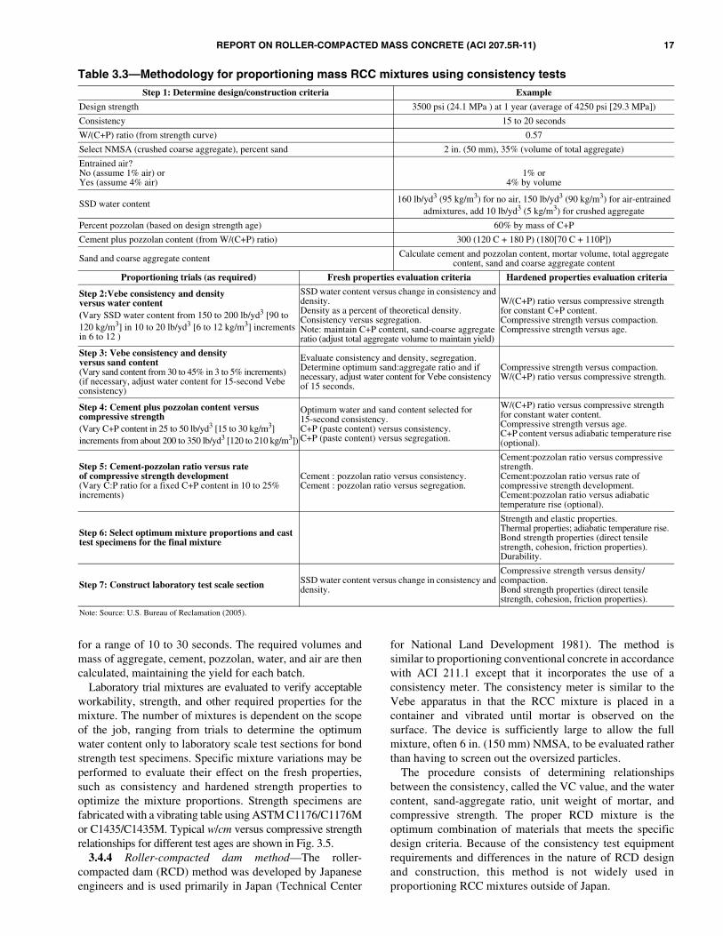
REPORT ON ROLLER-COMPACTED MASS CONCRETE (ACI 207.5R-11) 17
for a range of 10 to 30 seconds. The required volumes andmass of aggregate, cement, pozzolan, water, and air are thencalculated, maintaining the yield for each batch.
Laboratory trial mixtures are evaluated to verify acceptableworkability, strength, and other required properties for themixture. The number of mixtures is dependent on the scopeof the job, ranging from trials to determine the optimumwater content only to laboratory scale test sections for bondstrength test specimens. Specific mixture variations may beperformed to evaluate their effect on the fresh properties,such as consistency and hardened strength properties tooptimize the mixture proportions. Strength specimens arefabricated with a vibrating table using ASTM C1176/C1176Mor C1435/C1435M. Typical w/cm versus compressive strengthrelationships for different test ages are shown in Fig. 3.5.
3.4.4 Roller-compacted dam method—The roller-compacted dam (RCD) method was developed by Japaneseengineers and is used primarily in Japan (Technical Center
for National Land Development 1981). The method issimilar to proportioning conventional concrete in accordancewith ACI 211.1 except that it incorporates the use of aconsistency meter. The consistency meter is similar to theVebe apparatus in that the RCC mixture is placed in acontainer and vibrated until mortar is observed on thesurface. The device is sufficiently large to allow the fullmixture, often 6 in. (150 mm) NMSA, to be evaluated ratherthan having to screen out the oversized particles.
The procedure consists of determining relationshipsbetween the consistency, called the VC value, and the watercontent, sand-aggregate ratio, unit weight of mortar, andcompressive strength. The proper RCD mixture is theoptimum combination of materials that meets the specificdesign criteria. Because of the consistency test equipmentrequirements and differences in the nature of RCD designand construction, this method is not widely used inproportioning RCC mixtures outside of Japan.
Table 3.3—Methodology for proportioning mass RCC mixtures using consistency testsStep 1: Determine design/construction criteria Example
Design strength 3500 psi (24.1 MPa ) at 1 year (average of 4250 psi [29.3 MPa])
Consistency 15 to 20 seconds
W/(C+P) ratio (from strength curve) 0.57
Select NMSA (crushed coarse aggregate), percent sand 2 in. (50 mm), 35% (volume of total aggregate)
Entrained air?No (assume 1% air) orYes (assume 4% air)
1% or4% by volume
SSD water content 160 lb/yd3 (95 kg/m3) for no air, 150 lb/yd3 (90 kg/m3) for air-entrained admixtures, add 10 lb/yd3 (5 kg/m3) for crushed aggregate
Percent pozzolan (based on design strength age) 60% by mass of C+P
Cement plus pozzolan content (from W/(C+P) ratio) 300 (120 C + 180 P) (180[70 C + 110P])
Sand and coarse aggregate content Calculate cement and pozzolan content, mortar volume, total aggregate content, sand and coarse aggregate content
Proportioning trials (as required) Fresh properties evaluation criteria Hardened properties evaluation criteria
Step 2:Vebe consistency and densityversus water content(Vary SSD water content from 150 to 200 lb/yd3 [90 to 120 kg/m3] in 10 to 20 lb/yd3 [6 to 12 kg/m3] increments in 6 to 12 )
SSD water content versus change in consistency and density.Density as a percent of theoretical density.Consistency versus segregation.Note: maintain C+P content, sand-coarse aggregate ratio (adjust total aggregate volume to maintain yield)
W/(C+P) ratio versus compressive strength for constant C+P content.Compressive strength versus compaction.Compressive strength versus age.
Step 3: Vebe consistency and densityversus sand content(Vary sand content from 30 to 45% in 3 to 5% increments)(if necessary, adjust water content for 15-second Vebe consistency)
Evaluate consistency and density, segregation.Determine optimum sand:aggregate ratio and if necessary, adjust water content for Vebe consistency of 15 seconds.
Compressive strength versus compaction.W/(C+P) ratio versus compressive strength.
Step 4: Cement plus pozzolan content versuscompressive strength(Vary C+P content in 25 to 50 lb/yd3 [15 to 30 kg/m3]increments from about 200 to 350 lb/yd3 [120 to 210 kg/m3])
Optimum water and sand content selected for15-second consistency.C+P (paste content) versus consistency.C+P (paste content) versus segregation.
W/(C+P) ratio versus compressive strength for constant water content.Compressive strength versus age.C+P content versus adiabatic temperature rise (optional).
Step 5: Cement-pozzolan ratio versus rateof compressive strength development(Vary C:P ratio for a fixed C+P content in 10 to 25% increments)
Cement : pozzolan ratio versus consistency.Cement : pozzolan ratio versus segregation.
Cement:pozzolan ratio versus compressive strength.Cement:pozzolan ratio versus rate of compressive strength development.Cement:pozzolan ratio versus adiabatictemperature rise (optional).
Step 6: Select optimum mixture proportions and cast test specimens for the final mixture
Strength and elastic properties.Thermal properties; adiabatic temperature rise.Bond strength properties (direct tensile strength, cohesion, friction properties).Durability.
Step 7: Construct laboratory test scale section SSD water content versus change in consistency and density.
Compressive strength versus density/compaction.Bond strength properties (direct tensile strength, cohesion, friction properties).
Note: Source: U.S. Bureau of Reclamation (2005).

18 REPORT ON ROLLER-COMPACTED MASS CONCRETE (ACI 207.5R-11)
3.4.5 Maximum density method—This method is ageotechnical engineering approach similar to that used fordeveloping soil-cement- and cement-stabilized basemixtures (Reeves and Yates 1985). Instead of determiningthe water content by Vebe time or visual performance, thedesired water content is determined by moisture-densityrelationship of compacted specimens using ASTM D1557.Various modifications to the ASTM standard have beenfound to be desirable because the ASTM D1557 method wasnot developed for material larger than 3/4 in. (19.0 mm) indiameter (Method D is not included in the current standard),and is not suitable at relatively high levels of workability(Arnold et al. 1992). Proportioning by this approach is alsocovered in Appendix 3.7 of ACI 211.3R.
3.5—Laboratory trial mixtures3.5.1 General—It is recommended that a series of mixtures
be proportioned and laboratory trial-mixed to encompass thepotential range of performance requirements. This practicewill allow later mixture modifications or adjustments withoutnecessarily repeating the mixture evaluation process. Finaladjustments should be made based on full-size field trialbatches, preferably in a test strip or section where workabilityand compactibility can be observed.
3.5.2 Visual examination of fresh concrete—Severalcharacteristics can be determined by visual examination oflaboratory-prepared trial mixtures. Distribution of aggregatein the mixture, cohesiveness, and tendency for segregationare observable by handling the mixture on the lab floor withshovels. The texture of the mixture (harsh, unworkable,gritty, pasty, or smooth) can be seen and felt with the hand.These characteristics should be recorded for each mixture.
3.5.3 Testing—Laboratory tests, including temperature,consistency, unit weight, and air content, should beperformed by ACI-certified technicians on the fresh RCCproduced from each trial mixture. In addition, specimens shouldbe prepared for compressive strength testing at various ages,usually 7, 28, 90, 180 days, and 1 year to indicate the strengthgain characteristics of each mixture. These specimens can alsobe used for determination of static modulus of elasticity andPoisson’s ratio at selected ages. Additional specimens shouldalso be fabricated for splitting tensile strength (ASTM C496/C496M) or direct tensile strength at various ages to establishtheir relationship to compressive strength, and to provideparameters for use in structural analysis.
On major projects, specimens for thermal properties,including adiabatic temperature rise, coefficient of thermalexpansion, specific heat, thermal conductivity, and diffusivityare usually cast from one or more selected RCC mixtures.Specimens for specialized tests such as creep, tensile straincapacity, and shear strength may also be cast from thesemixtures. Many commercial laboratories are not equipped toconduct these tests, and special arrangements may be requiredwith the U.S. Army Corps of Engineers, U.S. Bureau ofReclamation, or universities that have the equipment andfacilities for this work. Commercial laboratories used shouldbe accredited in accordance with ASTM C1077 and E329.
3.6—Field adjustmentsThe primary purpose of laboratory mixture proportioning
is to provide proportions that when batched, mixed, andplaced in the field, will perform as intended. Laboratoryconditions, however, seldom perfectly duplicate fieldconditions due to ambient temperature and humidity,
Fig. 3.5—Compressive strength versus w/cm for mixtures with clean graded aggregates.
REPORT ON ROLLER-COMPACTED MASS CONCRETE (ACI 207.5R-11) 19
batching accuracies, differences in mixer size and mixingaction, changes in materials and material grading, compactionequipment, RCC curing, and time between adding water andcompaction. In spite of these differences, laboratory mixtureproportioning has proven to be an effective means to ensureRCC performance and to minimize field adjustments.
Field adjustments should include: 1) adjustment of aggregatepercentages based on stockpile grading for each individualsize range to produce the required combined grading; 2)correction of batch weights for aggregate moisturecontents; and 3) adjustment of water content for the desiredconsistency or degree of workability based on consistency andworkability of the mixture. Field adjustments should be donewith caution to ensure the original mixture w/cm or other criticalmixture requirements are not exceeded or misrepresented.
Before use in permanent work, it is recommended that theproposed RCC mixture be proportioned and mixed in full-size batches and placed, spread, and compacted in a test stripor section using the specified construction procedures. Thetest strip or section will provide valuable information on theneed for minor mixture modifications, and can be used todetermine the number of roller passes required for fullcompaction of the RCC mixture. A test strip or section canalso be used to visually examine the condition of lift jointsand potential for mixture segregation.
CHAPTER 4—PROPERTIES OF HARDENED ROLLER-COMPACTED CONCRETE
4.1—GeneralThe properties of hardened RCC are similar to those of mass
concrete. Some differences between RCC and conventionalmass concrete exist, however, primarily due to differences inrequired strength, paste volume, and voids content of the RCCmixtures. Most RCC mixtures are not air entrained and mayalso use aggregates that do not meet the quality or gradingrequirements of conventional mass concrete. RCC mixturesmay also use a higher percentage of pozzolan, which affects therate of strength gain, workability, and heat generation of themixture. Because some RCC mixtures may use lower-qualityaggregates and lower cementitious contents than conventionalconcretes, the range of hardened properties of RCC is greaterthan the range of properties of conventional concrete.
Designers should also be aware of the potential forincreased variability of hardened RCC properties due to thepotential for greater variations in materials and degree ofcompaction compared with conventional concrete. Lower-quality aggregates are those that may not meet the requirementsfor conventional concrete aggregates, either in durability orgrading, or those that have been processed without washing.The use of these materials should be carefully considered bythe designer and evaluated based on required performance.The rapid placing rates common in RCC construction canplace construction loads on concrete before it reaches itsinitial set; therefore, early-age testing of performance maybe needed for the design. The designer should be aware ofthe potential impact of low early-age strength onconstruction activities such as form support, vehicle access,and lift surface cleanup.
4.2—Strength4.2.1 Compressive strength—Compressive strength tests
are performed in accordance with ASTM C39/C39M duringthe design phase to determine mixture proportion requirements,and also to optimize combinations of cementitious materialsand aggregates. Compressive strength is used to satisfydesign loading requirements and also as an indicator of otherstrength properties or durability. Tests of cores from trialplacement areas may be used to evaluate strength of RCC fordesign purposes, and also to evaluate the effects of compactionmethods on these properties. During construction, compressivestrength tests are used to confirm design properties, to evaluatemixture variability, and to provide data for future designs.Cores extracted in accordance with ASTM C42/C42M afterconstruction is complete may be used to confirm designassumptions, construction practices, and may be used tofurther evaluate in-place properties of the structure. It isimportant to recognize that the compressive strength testresults during construction will lag far behind production, andthat maintaining quality can only be achieved as the RCC ismixed, placed, and compacted. Additionally, it is difficult to getreliable compressive strength results from low-strength corestaken too early following construction (though the cores can beused to evaluate compaction).
The compressive strength of RCC is influenced by watercontent, cementitious content, properties of the cementitiousmaterials, aggregate grading, aggregate quality, and the degreeof compaction. For fully-compacted RCC, the traditionalinfluence of w/cm on compressive strength is valid. Replace-ment of cement in an RCC mixture with pozzolan typicallydelays the early strength development of RCC. Mixturesproportioned for later-age strengths, such as at 180 days or1 year, often show no loss in strength, resulting in replacementof a significant portion of cement with pozzolan (Dolen 2003).
RCC mixtures with low cementitious contents or poorly-graded aggregates may not achieve anticipated strengthlevels if aggregate voids are not completely filled. For thesemixtures, the addition of nonplastic fines or rock dust hasbeen beneficial in filling voids, thus increasing the densityand strength. The use of plastic (clay) fines in RCC mixturesadversely affects strength and workability and, therefore, isnot recommended.
Significant differences in compaction have been observedto affect the strength of RCC in both the laboratory and incore samples extracted from in-place construction. Forlaboratory specimens, the energy imparted to the freshmixture should be sufficient to achieve full compaction, orstrength will not reach the required level due to increasedvoids. The compactive effort in the laboratory may becompared with cores extracted from a trial placement ofsimulated construction, provided that the test section hassufficient strength to be cored. The compressive strength ofconcrete will also decrease due to insufficient compactionthat can occur near the bottom of the lift when RCC haspoor workability. Not only does this affect compressivestrength, but also density, bond strength, and permeability.Compressive strength might also decrease due to delays incompleting compaction. Mixtures containing fly ash,
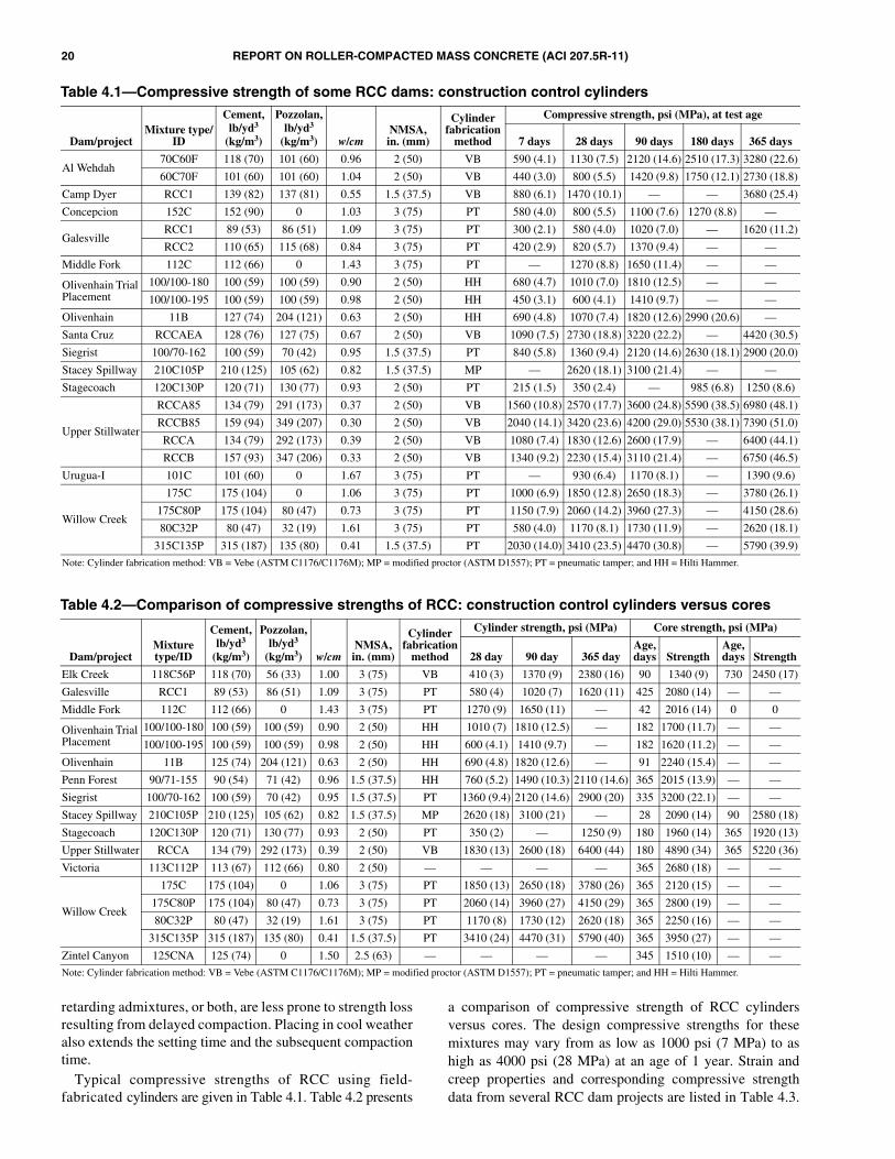
20 REPORT ON ROLLER-COMPACTED MASS CONCRETE (ACI 207.5R-11)
retarding admixtures, or both, are less prone to strength lossresulting from delayed compaction. Placing in cool weatheralso extends the setting time and the subsequent compactiontime.
Typical compressive strengths of RCC using field-fabricated cylinders are given in Table 4.1. Table 4.2 presents
a comparison of compressive strength of RCC cylindersversus cores. The design compressive strengths for thesemixtures may vary from as low as 1000 psi (7 MPa) to ashigh as 4000 psi (28 MPa) at an age of 1 year. Strain andcreep properties and corresponding compressive strengthdata from several RCC dam projects are listed in Table 4.3.
Table 4.1—Compressive strength of some RCC dams: construction control cylinders
Dam/projectMixture type/
ID
Cement, lb/yd3
(kg/m3)
Pozzolan,lb/yd3
(kg/m3) w/cmNMSA,in. (mm)
Cylinder fabrication
method
Compressive strength, psi (MPa), at test age
7 days 28 days 90 days 180 days 365 days
Al Wehdah70C60F 118 (70) 101 (60) 0.96 2 (50) VB 590 (4.1) 1130 (7.5) 2120 (14.6) 2510 (17.3) 3280 (22.6)
60C70F 101 (60) 101 (60) 1.04 2 (50) VB 440 (3.0) 800 (5.5) 1420 (9.8) 1750 (12.1) 2730 (18.8)
Camp Dyer RCC1 139 (82) 137 (81) 0.55 1.5 (37.5) VB 880 (6.1) 1470 (10.1) — — 3680 (25.4)
Concepcion 152C 152 (90) 0 1.03 3 (75) PT 580 (4.0) 800 (5.5) 1100 (7.6) 1270 (8.8) —
GalesvilleRCC1 89 (53) 86 (51) 1.09 3 (75) PT 300 (2.1) 580 (4.0) 1020 (7.0) — 1620 (11.2)
RCC2 110 (65) 115 (68) 0.84 3 (75) PT 420 (2.9) 820 (5.7) 1370 (9.4) — —
Middle Fork 112C 112 (66) 0 1.43 3 (75) PT — 1270 (8.8) 1650 (11.4) — —
Olivenhain Trial Placement
100/100-180 100 (59) 100 (59) 0.90 2 (50) HH 680 (4.7) 1010 (7.0) 1810 (12.5) — —
100/100-195 100 (59) 100 (59) 0.98 2 (50) HH 450 (3.1) 600 (4.1) 1410 (9.7) — —
Olivenhain 11B 127 (74) 204 (121) 0.63 2 (50) HH 690 (4.8) 1070 (7.4) 1820 (12.6) 2990 (20.6) —
Santa Cruz RCCAEA 128 (76) 127 (75) 0.67 2 (50) VB 1090 (7.5) 2730 (18.8) 3220 (22.2) — 4420 (30.5)
Siegrist 100/70-162 100 (59) 70 (42) 0.95 1.5 (37.5) PT 840 (5.8) 1360 (9.4) 2120 (14.6) 2630 (18.1) 2900 (20.0)
Stacey Spillway 210C105P 210 (125) 105 (62) 0.82 1.5 (37.5) MP — 2620 (18.1) 3100 (21.4) — —
Stagecoach 120C130P 120 (71) 130 (77) 0.93 2 (50) PT 215 (1.5) 350 (2.4) — 985 (6.8) 1250 (8.6)
Upper Stillwater
RCCA85 134 (79) 291 (173) 0.37 2 (50) VB 1560 (10.8) 2570 (17.7) 3600 (24.8) 5590 (38.5) 6980 (48.1)
RCCB85 159 (94) 349 (207) 0.30 2 (50) VB 2040 (14.1) 3420 (23.6) 4200 (29.0) 5530 (38.1) 7390 (51.0)
RCCA 134 (79) 292 (173) 0.39 2 (50) VB 1080 (7.4) 1830 (12.6) 2600 (17.9) — 6400 (44.1)
RCCB 157 (93) 347 (206) 0.33 2 (50) VB 1340 (9.2) 2230 (15.4) 3110 (21.4) — 6750 (46.5)
Urugua-I 101C 101 (60) 0 1.67 3 (75) PT — 930 (6.4) 1170 (8.1) — 1390 (9.6)
Willow Creek
175C 175 (104) 0 1.06 3 (75) PT 1000 (6.9) 1850 (12.8) 2650 (18.3) — 3780 (26.1)
175C80P 175 (104) 80 (47) 0.73 3 (75) PT 1150 (7.9) 2060 (14.2) 3960 (27.3) — 4150 (28.6)
80C32P 80 (47) 32 (19) 1.61 3 (75) PT 580 (4.0) 1170 (8.1) 1730 (11.9) — 2620 (18.1)
315C135P 315 (187) 135 (80) 0.41 1.5 (37.5) PT 2030 (14.0) 3410 (23.5) 4470 (30.8) — 5790 (39.9)
Note: Cylinder fabrication method: VB = Vebe (ASTM C1176/C1176M); MP = modified proctor (ASTM D1557); PT = pneumatic tamper; and HH = Hilti Hammer.
Table 4.2—Comparison of compressive strengths of RCC: construction control cylinders versus cores
Dam/projectMixture type/ID
Cement, lb/yd3
(kg/m3)
Pozzolan,lb/yd3
(kg/m3) w/cmNMSA,in. (mm)
Cylinder fabrication
method
Cylinder strength, psi (MPa) Core strength, psi (MPa)
28 day 90 day 365 dayAge, days Strength
Age, days Strength
Elk Creek 118C56P 118 (70) 56 (33) 1.00 3 (75) VB 410 (3) 1370 (9) 2380 (16) 90 1340 (9) 730 2450 (17)
Galesville RCC1 89 (53) 86 (51) 1.09 3 (75) PT 580 (4) 1020 (7) 1620 (11) 425 2080 (14) — —
Middle Fork 112C 112 (66) 0 1.43 3 (75) PT 1270 (9) 1650 (11) — 42 2016 (14) 0 0
Olivenhain Trial Placement
100/100-180 100 (59) 100 (59) 0.90 2 (50) HH 1010 (7) 1810 (12.5) — 182 1700 (11.7) — —
100/100-195 100 (59) 100 (59) 0.98 2 (50) HH 600 (4.1) 1410 (9.7) — 182 1620 (11.2) — —
Olivenhain 11B 125 (74) 204 (121) 0.63 2 (50) HH 690 (4.8) 1820 (12.6) — 91 2240 (15.4) — —
Penn Forest 90/71-155 90 (54) 71 (42) 0.96 1.5 (37.5) HH 760 (5.2) 1490 (10.3) 2110 (14.6) 365 2015 (13.9) — —
Siegrist 100/70-162 100 (59) 70 (42) 0.95 1.5 (37.5) PT 1360 (9.4) 2120 (14.6) 2900 (20) 335 3200 (22.1) — —
Stacey Spillway 210C105P 210 (125) 105 (62) 0.82 1.5 (37.5) MP 2620 (18) 3100 (21) — 28 2090 (14) 90 2580 (18)
Stagecoach 120C130P 120 (71) 130 (77) 0.93 2 (50) PT 350 (2) — 1250 (9) 180 1960 (14) 365 1920 (13)
Upper Stillwater RCCA 134 (79) 292 (173) 0.39 2 (50) VB 1830 (13) 2600 (18) 6400 (44) 180 4890 (34) 365 5220 (36)
Victoria 113C112P 113 (67) 112 (66) 0.80 2 (50) — — — — 365 2680 (18) — —
Willow Creek
175C 175 (104) 0 1.06 3 (75) PT 1850 (13) 2650 (18) 3780 (26) 365 2120 (15) — —
175C80P 175 (104) 80 (47) 0.73 3 (75) PT 2060 (14) 3960 (27) 4150 (29) 365 2800 (19) — —
80C32P 80 (47) 32 (19) 1.61 3 (75) PT 1170 (8) 1730 (12) 2620 (18) 365 2250 (16) — —
315C135P 315 (187) 135 (80) 0.41 1.5 (37.5) PT 3410 (24) 4470 (31) 5790 (40) 365 3950 (27) — —
Zintel Canyon 125CNA 125 (74) 0 1.50 2.5 (63) — — — — 345 1510 (10) — —
Note: Cylinder fabrication method: VB = Vebe (ASTM C1176/C1176M); MP = modified proctor (ASTM D1557); PT = pneumatic tamper; and HH = Hilti Hammer.

REPORT ON ROLLER-COMPACTED MASS CONCRETE (ACI 207.5R-11) 21
Figures 4.1 and 4.2 show compressive strength curvesdeveloped for two different aggregates using a maximumdensity method for mixture proportioning.
4.2.2 Tensile strength—Tensile strength of RCC isrequired for design loadings, including dynamic loading andin the thermal analysis. Table 4.4 shows direct tensilestrength values for core samples extracted from severalprojects. The ratios of direct tensile-to-compressive strengthfor parent (unjointed) RCC mixtures have typically averagedapproximately 4 to 8%, depending on aggregate quality,
strength, age, and test method. Mixtures with low cementitiousmaterials content, or those with lower-quality or coatedaggregates, or both, will have corresponding lower directtensile strengths. The ratio of direct tensile-to-compressivestrength of both RCC and conventional mass concrete willusually decrease with increasing age and compressive strength(Schrader 1994). The direct tensile strength of concrete is lessthan the splitting (indirect) tensile strength of unjointedconcrete. Splitting (indirect) tensile testing in accordance with
Table 4.3—Strain and creep properties of some laboratory RCC mixtures
Dam/projectCement,
lb/yd3 (kg/m3)Pozzolan,
lb/yd3 (kg/m3) w/cmLoading age,
days
Creep coefficients
Compressive strength, psi (MPa)
Modulus of elasticity,106/psi (GPa)
1/E, 10–6/psi(10–6/KPa) f(K)
Concepcion
152 (90) 0 1.20 7 1.4 (0.20) 0.12 640 (4) —
152 (90) 0 1.20 28 0.73 (0.11) 0.08 980 (7) 1.40 (10)
152 (90) 0 1.20 90 0.47 (0.07) 0.03 1250 (9) 2.10 (14)
Upper Stillwater
182 (108) 210 (125) 0.47 28 1.05 (0.15) 0.11 2150 (15) 1.03 (7)
129 (77) 286 (170) 0.43 28 0.66 (0.10) 0.04 2030 (14) 1.49 (10)
129 (77) 286 (170) 0.43 180 0.57 (0.08) 0.01 4170 (29) 1.69 (12)
121 (72) 269 (160) 0.45 180 0.62 (0.09) 0.02 3220 (22) 1.26 (9)
182 (108) 210 (125) 0.47 365 0.57 (0.08) 0.02 4990 (34) 1.75 (12)
121 (72) 269 (160) 0.45 365 0.57 (0.08) 0.01 4870 (34) 1.63 (11)
182 (108) 210 (125) 0.47 90 0.84 (0.12) 0.06 3410 (24) 1.32 (9)
129 (77) 286 (170) 0.43 365 0.53 (0.08) 0.02 5140 (35) 1.82 (13)
182 (108) 210 (125) 0.47 180 0.67 (0.10) 0.03 4120 (28) 1.58 (11)
Willow Creek
80 (47) 32 (19) 1.61 7 1.97 (0.29) 0.20 580 (4) 1.20 (8)
175 (104) 80 (47) 0.73 7 0.58 (0.08) 0.08 1150 (8) 2.40 (17)
80 (47) 32 (19) 1.61 28 1.09 (0.16) 0.11 1170 (8) 1.59 (11)
80 (47) 32 (19) 1.61 90 0.52 (0.08) — 1730 (12) 1.91 (13)
175 (104) 0 1.06 7 0.48 (0.07) 0.08 1000 (7) 2.20 (15)
175 (104) 0 1.06 28 0.34 (0.05) 0.05 1850 (13) 2.67 (18)
Zintel Canyon
100 (59) 0 2.00 28 0.76 (0.11) 0.08 630 (4) 1.54 (11)
100 (59) 0 2.00 90 0.47 (0.07) — 1090 (8) 2.15 (15)
100 (59) 0 2.00 365 0.39 (0.06) — 1550 (11) 2.57 (18)
200 (119) 0 1.00 7 0.76 (0.11) 0.05 990 (7) 1.54 (11)
200 (119) 0 1.00 28 0.45 (0.07) 0.03 1620 (11) 2.39 (16)
200 (119) 0 1.00 90 0.40 (0.06) — 2130 (15) 2.47 (17)
200 (119) 0 1.00 365 0.30 (0.04) — 3100 (21) 3.28 (23)
100 (59) 0 2.00 7 1.43 (0.21) 0.09 280 (2) 0.68 (5)
Fig. 4.1—RCC strength curves that can be developed fromtests conducted on concretes with varying proportions ofcement for high-quality aggregates.
Fig. 4.2—RCC strength curves developed for lesser-qualityaggregates.

22 REPORT ON ROLLER-COMPACTED MASS CONCRETE (ACI 207.5R-11)
ASTM C496/C496M may be used, with appropriate datareduction, to determine parent tensile strength.
If the tensile strength of lift joints is needed, direct tensilestrength testing is required. Designers should also consideranticipated construction and joint surface treatment methodsin their design tensile strength assumptions. The directtensile strength of RCC lift joints is not only dependent onthe strength of the RCC mixture, but also on the maturity ofthe joint, the lift-joint surface preparation, degree ofcompaction and segregation at the lift interface, themaximum aggregate size, and the use and strength of abonding mixture applied to the lift surface. Inadequate lift-surface cleanup, poor consolidation, or both, can drasticallyreduce the direct tensile strength of lift joints. Varioussurface preparation methods are discussed in Chapter 6.With adequate attention to lift surface preparation, thedirect tensile strength of RCC lift joints averaged approxi-mately 5% of the compressive strength. Testing of liftjoints constructed using planned mixtures and placingprocedures should be performed to confirm that requiredtensile strength can be achieved. The splitting tensilestrength of the parent (unjointed) RCC has been assumed tobe approximately 10% of the compressive strength.
4.2.3 Shear strength—Shear strength of lift joints is oftena critical hardened property for RCC gravity dams. Totalshear strength is the sum of cohesion plus internal friction forbonded, intact, lift joints. Shear resistance of unbonded liftjoints includes apparent cohesion and sliding friction resistancebetween the lift surfaces. The minimum shear within thestructure occurs at construction (lift) joints between lifts ofRCC. Typical shear test values for parent RCC and bondedand unbonded joints are given in Table 4.5.
The designer should determine the required shear strengthof lift joints, and also estimate a percentage of bonded liftjoint that is likely to result from the planned constructionmethods. Past experience has shown that assuming 100%bonded lift joints is generally not valid. Decreased bond(cohesion) may result from insufficient paste volume in theRCC mixture, poor cleanup, excessive rain, excessive curewater, drying or freezing of the lift surface, and segregationor poor consolidation near the bottom of an RCC lift. Thebond strength of RCC lift joints may be increased by usinggood construction joint surface treatment methods,increasing the strength or cementitious content of themixture, placing RCC rapidly over a fresh joint surface, orapplication of a supplemental bonding mixture of beddingmortar or concrete between lifts. The cohesion of bonded liftjoints in Table 4.5 averaged approximately 6 to 7.5% of thecompressive strength for mixtures without and with a bondingmixture, respectively. Although difficult to quantify, the typeof joint preparation, joint maturity, and moisture condition cansignificantly affect shear strength of bonded RCC lift joints.Thus, the shear properties can be significantly impacted byconstruction placing rates and ambient weather conditionsthat are not directly under the control of the designer.
The unconfined shear strength of unjointed (parent) RCCin Table 4.5 averaged approximately 13% of its compressivestrength and ranged from approximately 8 to 21%. Theunconfined shear strength of conventionally placed concrete,as determined by direct shear tests, generally ranges fromapproximately 20 to 25% of its compressive strength, but aconservative value of approximately 10% is often used indesign. The coefficient of friction within the mass has beenusually taken to be 1.0 (φ = 45 degrees) for RCC if noproject-specific tests have been conducted.
Table 4.4—Direct tensile strength of drilled cores of RCC dams
Dam/project
Mixturetype/ID
Cement, lb/yd3
(kg/m3)
Pozzolan,lb/yd3 (kg/
m3) w/cmNMSA,in. (mm)
Jointtype
Age,days
Compressivestrength,psi (MPa)
Tensilestrength,psi (MPa)
Vebetime, s
Percent bondedjoints
Joint maturity,
°F-hTesttype Comments
Mujib 143/0-6.0 143 (85) 0 — 2 (50) P 365 1870 (12.9) 230 (1.6) 30 to 45 — — DT
Olivenhain
11B 125 (74) 204 (121) 0.63 2 (50) NB 90 2030 (14.0) 124 (0.9) 15 95 240 DT
11B 125 (74) 204 (121) 0.63 2 (50) NB 90 2030 (14.0) 43 (0.3) 15 67 1700 DT
11B 125 (74) 204 (121) 0.63 2 (50) B 90 2030 (14.0) 102 (0.7) 15 60 1740 DT *
11B 125 (74) 204 (121) 0.63 2 (50) B 90 2030 (14.0) 169 (1.2) 15 75 7300 DT †
150/125-200 150 (89) 125 (74) 0.73 2 (50) B 90 1200 (8.3) 105 (0.7) 15 70 320 DT
150/125-200 150 (89) 125 (74) 0.73 2 (50) B 90 1200 (8.3) 123 (0.8) 15 90 1110 DT
150/125-200 150 (89) 125 (74) 0.73 2 (50) B 90 1200 (8.3) 140 (1.0) 15 90 6270 DT
Olivenhain Design Trial Placement
100/100-195 100 (59) 100 (59) 0.98 2 (50) B 200 1620 (11.2) 142 (1.0) 16 79 1170 DT
100/100-195 100 (59) 100 (59) 0.98 2 (50) B 200 1620 (11.2) 144 (1.0) 16 97 170 DT
100/100-195 100 (59) 100 (59) 0.98 2 (50) P 200 1620 (11.2) 151 (1.0) 16 — — DT
UpperStillwater
RCC B 150 (89) 328 (195) 0.35 2 (50) NB 5000 4630 (31.9) 250 (1.7) 15 90 — DT
RCC B 150 (89) 328 (195) 0.35 2 (50) P 5000 4630 (31.9) 230 (1.6) 15 90 — DT
RCC B 150 (89) 328 (195) 0.35 2 (50) NB 365 5130 (35.4) 190 (1.3) 15 80 — DT
RCC A 134 (80) 291 (173) 0.37 2 (50) P 730 6500 (44.8) 280 (1.9) 30 60 — DT
RCC A 134 (80) 291 (173) 0.37 2 (50) NB 730 6500 (44.8) 230 (1.6) 30 60 — DT
RCC A 134 (80) 292 (174) 0.39 2 (50) NB 365 5220 (36.0) 200 (1.4) 15 80 — DT*Surface vacuumed before placing bedding mixture.†Surface pressure washed and vacuumed before placing bedding mixture.Notes: Joint type: B = bedding concrete or mortar; NB = no bedding; and P = parent concrete. Test type: DT = direct tensile; ST = splitting (indirect) tensile.

REPORT ON ROLLER-COMPACTED MASS CONCRETE (ACI 207.5R-11) 23
4.3—Elastic properties4.3.1 Modulus of elasticity—Modulus of elasticity is
typically a required input parameter for most stress analysisprograms. In linear-elastic numerical analysis, a lowmodulus of elasticity may be desirable because it maypredict lower stresses from an assumed linear stress-strainrelationship versus a high-modulus material. In brittle
materials (and not modeled in linear elastic theory),however, ultimate failure strains used to predict stress mayalready be in the cracking (nonlinear) range for a low-modulusmaterial, thus not correctly predicting stress by linear-elasticbehavior. Principal factors affecting the elastic properties ofRCC are age, strength, paste volume, and aggregate type.Generally, for a given aggregate type, the modulus of elasticity
Table 4.5—Shear performance of drilled cores in RCC dams
Dam/project
Mixture type/ID
Cement, lb/yd3
(kg/m3)
Pozzolan, lb/yd3
(kg/m3) w/cmNMSA,in. (mm)
Joint type
Age, days
Core compressive
strength,psi (MPa)
Peakcohesion, psi (kPa)
Shear φ, deg
Residual shear
cohesion, psi (kPa)
Residual shear φ,
deg
Vebeconsis-tency, s
Bonded joints, %
Joint maturity,
°F-h* Comments
Cuchillo Negro
130C100P 130 (77) 100 (59) 0.99 3 (75) B 750 2530 (17) 225 (1551) 58 — — — — —
130C100P 130 (77) 100 (59) 0.99 3 (75) P 750 2530 (17) 360 (2482) 52 — — — — —
130C100P 130 (77) 100 (59) 0.99 3 (75) NB 750 2530 (17) 100 (689) 62 — — — — —
Elk Creek118C56P 118 (70) 56 (33) 1.00 3 (75) P 90 1340 (9) 225 (1551) 46 — — 21 — —
118C56P 118 (70) 56 (33) 1.00 3 (75) B 90 1340 (9) 125 (862) 49 — 49 — 58 —
Galesville
RCC1 89 (51) 86 (51) 1.09 3 (75) NB 415 2080 (14) 110 (758) 67 80 (552) 40 — 24 500
RCC1 89 (51) 86 (51) 1.09 3 (75) B 415 2080 (14) 330 (2275) 52 70 (483) 43 — 76 —
RCC1 89 (51) 86 (51) 1.09 3 (75) P 415 2080 (14) 380 (2620) 33 95 (655) 45 — — —
Mujib
143/0-6.0 143 (85) 0 (0) — 2 (50) P 365 1870 (12.9) 250 (1700) — — — 30 to 45 — — Conveyor delivery
143/0-6.0 143 (85) 0 (0) — 2 (50) P 365 1870 (12.9) 220 (1500) — — — 30 to 45 — — Truck delivery
143/0-6.0 143 (85) 0 (0) — 2 (50) B 365 1870 (12.9) 170 (1200) — — — 30 to 45 — — Conveyor delivery
143/0-6.0 143 (85) 0 (0) — 2 (50) B 365 1870 (12.9) 160 (1100) — — — 30 to 45 — — Truck delivery
Olivenhain TrialPlacement
100/100-195 100 (59) 100 (59) 0.98 2 (50) B 205 1620 (11.2) 350 (2410) 63 109 (751) 39 16 79 1130
100/100-195 100 (59) 100 (59) 0.98 2 (50) B 207 1620 (11.2) 305 (2100) 62 79 (540) 50 16 97 170
100/100-195 100 (59) 100 (59) 0.98 2 (50) P 206 1620 (11.2) 337 (2320) 62 78 (540) 50 16 — —
Saluda TrialPlacement
104/89-6.0 175 (104) 150 (89) 0.89 1.5 (37.5) NB 365 2760 (19.0) 82 (570) 56 0 47 15 to 20 † 375 Lightly washed
104/89-6.0 175 (104) 150 (89) 0.89 1.5 (37.5) B 365 2760 (19.0) 210 (1480) 67 0 49 15 to 20 † 375 Lightly washed
104/89-6.0 175 (104) 150 (89) 0.89 1.5 (37.5) B 365 2760 (19.0) 10 (70) 66 0 45 15 to 20 † 750 Lightly washed
74/89-6.3 125 (74) 150 (89) 0.91 1.5 (37.5) NB 365 2610 (18.0) 12 (80) 49 0 42 38 † 375 Lightly washed
89/89-6.8 150 (89) 150 (89) 0.86 1.5 (37.5) NB 365 3190 (22.0) 46 (320) 45 0 43 25 to 35 † 750 Air blown
89/89-6.8 150 (89) 150 (89) 0.86 1.5 (37.5) B 365 3190 (22.0) 65 (450) 61 0 52 25 to 35 † 750 Air blown
89/89-6.8 150 (89) 150 (89) 0.86 1.5 (37.5) NB 365 3190 (22.0) 65 (450) 47 0 43 25 to 35 † 375 Air blown
89/89-6.8 150 (89) 150 (89) 0.86 1.5 (37.5) NB 365 3190 (22.0) 81 (560) 49 0 43 25 to 35 † 125 Air blown
89/89-6.8 150 (89) 150 (89) 0.86 1.5 (37.5) B 365 3190 (22.0) 38 (260) 67 0 42 25 to 35 † 125 Air blown
104/89- 175 (104) 150 (89) — 1.5 (37.5) B 365 2760 (19.0) 0 (0) 64 0 45 35 † 375 Air blown
104/89- 175 (104) 150 (89) — 1.5 (37.5) NB 365 2760 (19.0) 8 (55) 36 0 44 35 † 375 Air blown
UpperStillwater
RCCA 134 (79) 292 (173) 0.39 2 (50) NB 365 5220 (36) 450 (3103) 53 30 (207) 49 17 80 —
RCCA 134 (79) 292 (173) 0.39 2 (50) NB 545 5590 (39) 560 (3821) 76 20 (138) 53 17 — —
RCCA85 134 (79) 291 (173) 0.37 2 (50) P 120 3870 (27) 300 (2068) 55 30 (207) 42 29 60 —
RCCA85 134 (79) 291 (173) 0.37 2 (50) NB 730 6510 (45) 440 (3034) 48 20 (138) 46 29 60 —
RCCB 150 (89) 328 (195) 0.35 2 (50) P 5000 4630 (31.9) 570 (3900) 49 — — 15 — —
RCCB 150 (89) 328 (195) 0.35 2 (50) NB 5000 4630 (31.9) 380 (2600) 52 — — 15 90 24-h
RCCB 150 (89) 328 (195) 0.35 2 (50) NB 5000 4630 (31.9) 650 (4500) 34 — — 15 90 12-h
Victoria
113C112P 113 (67) 112 (66) 0.80 2 (50) P 365 2680 (18) 280 (1931) 64 40 (276) 47 730 — —
113C112P 113 (67) 112 (66) 0.80 2 (50) B 365 2680 (18) 230 (1586) 69 10 (69) 44 — — —
113C112P 113 (67) 112 (66) 0.80 2 (50) NB 365 2680 (18) 170 (1172) 62 200 (1379) 48 — — —
Willow Creek
175C 175 (104) 0 1.06 3 (75) NB 200 — 185 (1278) 65 — — — 57 500
175C80P 175 (104) 80 (47) 0.73 3 (75) NB 200 — 186 (1279) 63 — — — 54 500
80C32P 80 (47) 32 (19) 1.61 3 (75) NB 200 — 115 (793) 62 — — — 58 500
Zintel Canyon
125CNA 125 (74) 0 1.50 2.5 (63) NB 345 1510 (10) 85 (586) 56 10 (69) 40 14 — —
125CNA 125 (74) 0 1.50 2.5 (63) B 345 1510 (10) 200 (1379) 54 10 (69) 40 14 65 —
125CNA 125 (74) 0 1.50 2.5 (63) P 345 1510 (10) 290 (1999) 56 0 55 14 — —
*Majority of Saluda test samples were purposely precracked at lift joint before testing.†Except as noted.Note: Joint type: B = bedding concrete or mortar; NB = no bedding; and P = parent concrete.

24 REPORT ON ROLLER-COMPACTED MASS CONCRETE (ACI 207.5R-11)
is a function of strength. Typical modulus of elasticity valuesfor a variety of RCC mixtures are shown in Tables 4.3 and 4.6.The modulus of elasticity in tension is typically assumed to bethe same as in compression.
4.3.2 Poisson’s ratio—Values of Poisson’s ratio for RCC,as indicated in Table 4.6, have ranged from approximately0.17 to 0.22, with lower values occurring at earlier ages andwith lower compressive strength mixtures. In general,Poisson’s ratio values for RCC are similar to values reportedfor conventional concrete mixtures.
4.4—Dynamic propertiesThe strength and material properties of conventional
concrete have been measured for cyclic loadings and rapidstrain rates to simulate dynamic loading conditions on damsduring earthquakes. The ultimate compressive and tensilestrength and elastic modulus generally increase under rapiddynamic loading conditions. To date, there are no knowncomparable test results for shear strength under similardynamic loading conditions.
The usual increase in concrete modulus during dynamicloading is well documented by laboratory tests and the use ofdynamic or rapid load concrete modulus for dynamic analysisis accepted practice (U. S. Bureau of Reclamation 1978;Clough and Zienkiewicz 1975; Lindvall, Richter, and
Associates 1975). A value of instantaneous dynamicconcrete modulus is approximately 25% greater than thestatic modulus of elasticity, and can be used for preliminarystudies in the absence of actual laboratory test data.
Dynamic strength values are dependent on the rate ofloading. The results from historical laboratory tests onconventional concrete indicate an approximate 30% increasefor compressive strength, and increases of slightly greaterthan 50% for tensile strength, based on splitting tensile ormodulus of rupture tests of cast specimens under rapiddynamic loading conditions (U.S. Bureau of Reclamation1977b; Raphael 1984; Soroushian et al. 1986). Recent testsof conventional mass concrete cores show the dynamiccompressive strength ranges from 75 to 145% of the staticstrength, the dynamic modulus of elasticity in compressionranges from 70 to 110% of the static value, and the dynamicsplitting tensile strength ranges from 80 to 130% of the staticsplitting tensile strength (Harris et al. 2000).
Laboratory testing should be performed to confirm thedynamic properties of RCC compared with static values.Currently, there are no published results of dynamic materialproperties tests for RCC. Field testing of existing RCC(based on both cast and cored specimens) shows thatconventional concrete exhibits similar material properties.
Table 4.6—Compressive strength and elastic properties of some laboratory RCC mixtures
Dam/project
Mixture type/ ID
Cylinder fabrication
method
NMSA, in.
(mm) w/cm
Compressive strength,psi (MPa)
Modulus of elasticity,million psi (GPa) Poisson’s ratio
7 day 28 day 90 day 365 day 7 day 28 day 90 day 365 day 7 day 28 day 90 day 365 day
Concepcion 152C PT 3(75) 1.03 640
(4.4)980 (6.8)
1250 (8.6)
1690 (11.7) — 1.10
(7.58)1.91
(13.17)3.31
(22.82) — 0.17 — —
Mujib 143/0-6.0 PT 2(50)
690 (4.8)
1020 (7.0)
1230 (8.5)
1870 (12.9)
0.9 (6.2)
1.62 (11.2)
2.77 (19.1)
3.39 (23.4) — — — —
Olivenhain
100/100-180 H 2(50) 0.90 600
(4.1)910 (6.3)
1440 (9.9)
2340 (16.1)
1.04 (7.17)
1.30 (8.97)
1.15 (7.93)
1.75 (12.07) — — — —
125/125-180 H 2(50) 0.72 640
(4.4)1110 (7.7)
1720 (11.9)
3050 (21.0) — 2.19
(15.10)2.90
(20.00)4.17
(28.76) — — — —
225/0-180 H 2(50) 0.80 1850
(12.8)2600 (17.9)
2820 (19.4)
3000 (20.7)
2.10 (14.48)
2.43 (16.75)
2.45 (16.90)
3.53 (24.34) — — — —
Santa Cruz 1e VB 2(50) 0.88 640
(4.4)1290 (8.9)
2180 (15.0)
3050 (21.0)
1.36 (9.38)
1.80 (12.41)
2.26 (15.58)
3.24 (22.34) 0.13 0.14 0.19 0.21
Siegrist 100/70 PT 1.5 (37.5) 0.95 630
(4.3)890 (6.1)
1320 (9.1)
2030 (14.0)
0.58 (4.00)
0.92 (6.34)
1.58 (10.89)
3.00 (20.68) — — — —
UpperStillwater
L1 VB 2(50) 0.47 1360
(9.4)2130 (14.7)
3510 (24.2)
5220 (36.0) — 1.03
(7.10)1.32
(9.10)1.71
(11.79) — 0.13 0.14 0.14
L2 VB 2(50) 0.45 770
(5.3)1220 (8.4)
2150 (14.8)
4780 (33.0) — 0.82
(5.65) — 1.59 (10.96) — 0.13 — 0.20
L3 VB 2(50) 0.43 1110
(7.7)1620 (11.2)
2770 (19.1)
4960 (34.2) — 0.92
(6.34) — 1.76 (12.14) — 0.13 — 0.18
Urugua-I 101C PT 3(75) 1.67 — 930
(6.4)1170 (8.1)
1390 (9.6) — 2.25
(15.51)3.12
(21.51)3.60
(24.82) — — — —
Willow Creek
175C PT 3(75) 1.06 1000
(6.9)1845 (12.7)
2650 (18.3)
3780 (26.1)
2.20 (15.17)
2.67 (18.41)
2.78 (19.17) — — 0.19 0.18 —
175C80P PT 3(75) 0.73 1150
(7.9)2060 (14.2)
3960 (27.3)
4150 (28.6)
2.40 (16.55)
2.91 (20.06)
3.25 (22.41) — — 0.21 0.21 —
80C23P PT 3(75) 1.61 580
(4.0)1170 (8.1)
1730 (11.9)
2620 (18.1)
1.20 (8.27)
1.59 (10.96)
1.91 (13.17) — — 0.14 0.17 —
Zintel Canyon
100C1975 PT 3(75) 2.00 280
(1.9)630 (4.3)
1090 (7.5)
1550 (10.7)
0.68 (4.69)
1.54 (10.62)
2.15 (14.82)
2.57 (17.72) — — 0.21 —
200C1975 PT 3(75) 1.00 990
(6.8)1620 (11.2)
2130 (14.7)
310 (21.4)
1.54 (10.62)
2.39 (16.48)
2.47 (17.03)
3.28 (22.62) — — 0.20 —
Note: Cylinder fabrication method: VB = Vebe (ASTM C1176/C1176M); PT = pneumatic tamper; HH = Hilti Hammer.

REPORT ON ROLLER-COMPACTED MASS CONCRETE (ACI 207.5R-11) 25
Thus, it is generally considered acceptable practice toassume comparable increases for compressive and tensilestrength and elastic modulus for RCC mixtures underdynamic loading conditions. In the absence of definitive testdata for dynamic shear strength of conventional concrete orRCC, designers should choose reasonable values for evaluatingdesigns for earthquake loads. The choice ranges from valuesof static shear strength to values based on the proportionalrelationship between ultimate compressive strength andshear strength. Until comparable testing of RCC specimensunder dynamic loading conditions has been accomplished toconfirm the validity of these relationships, a cautiousimplementation of this approach is suggested.
4.5—CreepCreep is a function of the material properties and proportions
of components in the RCC mixture, modulus of elasticity,and compressive strength. Generally, high-strength mixtureshave a more rigid cementing matrix and lower creep,whereas low-strength mixtures or those using aggregateswith low modulus of elasticity will produce concretes withhigher creep. Typical creep values for a variety of RCCmixtures are shown in Table 4.3. Higher creep properties aregenerally desirable to relieve stress and strain buildupresulting from foundation restraint, thermal conditions, andexterior loadings.
4.6—Volume change4.6.1 Drying shrinkage—Drying shrinkage is primarily
governed by the water content of the mixture and, to a lesserextent, by the degree of aggregate restraint. Compared withconventional mass concrete, the volume change from dryingshrinkage in RCC is similar or lower because of the reducedwater content.
4.6.2 Autogenous volume change—Autogenous volumechange is primarily a function of the material properties andproportions in the mixture. Similar to conventional concrete,autogenous volume change cannot be reliably predictedwithout laboratory testing. This is especially true for mixturesmade with an unusual cement, pozzolan, or aggregate.
4.7—Thermal propertiesThermal properties, including specific heat, conductivity,
diffusivity, coefficient of thermal expansion, and adiabatictemperature rise, are of primary concern for both conventionaland roller-compacted mass concrete. Thermal properties aregoverned by the thermal properties of the mixture constituents.Although values for conventional concrete and RCC aresimilar, the actual measured values can vary significantlydepending on aggregate type, cement, pozzolan chemistry,and cementitious content. For this reason, testing using thefull RCC mixture is recommended. Traditional test proceduresfor hardened concrete may not always be applicable to someRCC mixtures, particularly those with either low strength orhigh pozzolan contents. For example, the adiabatic temperaturerise of mass concrete is normally tested for approximately28 days, with most mixtures producing little temperature risebeyond that time. A high-pozzolan RCC mixture may have
significant delay in early-age temperature rise and increasedtemperature rise beyond 28 days. RCC mixtures with morethan approximately 30% pozzolan should be tested foradiabatic temperature rise and other properties to an age ofat least 56 days.
The adiabatic temperature rise is affected by the totalcementitious materials content and percentage of pozzolan inthe mixture. RCC mixtures with low cementitious materialscontent will have lower temperature rise than conventionalmass concrete mixtures. Typically, pozzolans, such as Class Fpozzolan, will produce an adiabatic temperature rise at 28 daysof approximately one-half that of an equivalent weight ofcement. Pozzolans may also reduce the rate of temperaturerise at early ages. Table 4.7 shows typical adiabatic tempera-ture rise and other thermal properties of some RCC mixtures.
4.8—Tensile strain capacityStrain is induced in concrete when a restrained volume
change occurs. When the volume change results in strain thatexceeds the tensile strain capacity of the material, a crackoccurs. The threshold strain value just before cracking is thetensile strain capacity of the material. Tensile strains inconcrete can be developed by external loads applied to thestructure as well as by volume changes induced throughdrying, reduction in temperature, and autogenous shrinkage.
The major factors affecting tensile strain capacity are thestrength and age of the concrete, rate of loading, type ofaggregate, aggregate shape (angular, as produced by crushing,versus natural round), and cementitious content.
As with other material properties, tensile strain capacitycan vary considerably because of the wide range of mixtureproportions and variety of aggregates used to produce RCC.Each mixture should be evaluated if tensile strain capacity isused for crack analysis. USACE (2000) recommendsdetermining the tensile strain capacity according to CRD-C 71.
4.9—PermeabilityThe permeability of RCC is largely dependent on voids in
the compacted mass together with porosity of the mortarmatrix, and is therefore almost totally controlled by mixtureproportioning, placement method, and degree of compaction.RCC will be relatively impervious when the mixture containssufficient paste and mortar, an adequate fine particledistribution that minimizes the air void system, limitedsegregation of coarse aggregate, and full compaction. Ingeneral, an unjointed mass of RCC proportioned with sufficientpaste will have permeability values similar to conventionalmass concrete. Test values typically range from 0.3 to 30 ×10–9 ft/min. (0.15 to 15 × 10–9 cm/s). High cementitiousmixtures tend to have lower permeability than lowcementitious mixtures.
If seepage occurs in RCC dams, it usually occurs along liftjoints or through contraction joints or cracks rather thanthrough the unjointed mass. If seepage occurs along liftjoints, it also indicates a reduction in shear and tensilestrength at this location.
Leakage can also be expected through cracks and monolithjoints, regardless of the permeability of the RCC. Although

26 REPORT ON ROLLER-COMPACTED MASS CONCRETE (ACI 207.5R-11)
generally not detrimental to the stability of a structure,leakage through cracks can result in an undesirable loss ofwater, create operational or maintenance problems, and beaesthetically undesirable. Leakage through vertical cracks canbe extremely difficult to stop or control without grouting,installation of external waterstops, or both. The best method ofpreventing leakage is to install stress relief (contraction) jointsin the mass RCC before filling and either control leakage withembedded waterstops and drains, seal the cracks on theupstream facing, or use a membrane facing system.
With time, natural calcification will generally reduceseepage through minor cracks and lift joints.
4.10—DurabilityRCC, like conventional mass concrete, is prone to deterio-
ration due to the effects of abrasion, freezing and thawing,and other factors such as alkali-aggregate reaction andsulfate attack.
4.10.1 Abrasion erosion—Abrasion erosion damageresults from the abrasive effects of waterborne sediments,ice, and other debris impinging on the RCC during operationof a hydraulic structure (ACI 210R). Abrasion erosionresistance is primarily governed by compressive strengthand quality of the aggregate. RCC pavements at heavy-dutyfacilities such as log storage yards and coal storage areas
Table 4.7—Thermal properties of some laboratory RCC mixtures
Dam/project
Mixture type/ID
Cement, lb/yd3 (kg/
m3)
Pozzolan, lb/yd3
(kg/m3)Aggregate
type
Specific heat,
Btu °F (J/kg °C)
Diffusivity, ft2/h (m2/h)
Conductivity,Btu/ft-h°F(W/m °K)
Coefficient of expansion
millionths/°F (millionths/°C)
Initial,°F (°C)
Adiabatictemperature rise
Comment
Change in °F (°C)
3 day 7 day 28 day
Concepcion 152CL 152(90)
0(0) Ignimbrite 0.25
(1047)0.03
(0.003) 1.1 (1.9) 6.2 (11) 67 (19.4)
21 (11.7)
24 (13.3)
25 (13.9) —
Coolidge 124C124 124(74)
124(74)
Volcanics/ alluvial — — — — 63
(17.2)23
(12.8)28
(15.6)35
(19.4) —
ElkCreek
113C28P 113(67)
28(17)
Basalt/sandstone — — — — 41
(5.0)11
(6.1)14
(7.8)20
(11.1) IP cement
118C56P 118(70)
56(33)
Basalt/sandstone
0.18 (754) — — — 43
(6.2)17
(9.4)21
(11.7)24
(13.3) —
94C38P 94(56)
38(23)
Basalt/sandstone
0.18 (754)
0.03(0.003) 1 (1.7) 3.9 (7.0) 44
(6.7)13
(7.2)16
(8.9)20
(11.1) —
Middle Fork 120C 120
(71) — Marlstone — — — — 60 (15.6)
17 (9.4)
22 (12.2)
27 (15.0) —
Milltown Hill 111C112 111
(66)112(66)
Andesite/ basalt
0.25 (1047)
0.05(0.005) 1.92 (3.3) 3.3 (5.9) 62
(16.7)17
(9.4)22
(12.2)30
(16.7)
Maximum 32°F
(18°C) at 54 days
Olivenhain
225/0-180
225(134)
0(0) Granodiorite — — — 5.4 (9.7) — — — — —
200/0-180
200(119)
0(0) Granodiorite — — — — 69
(38)28
(16)33
(18)35
(19) —
100/100-180
100(59)
100(59) Granodiorite 0.21
(880)0.03
(0.003) 0.94 (1.6) — 58(32)
17 (9.4)
21 (12)
24(13) —
Santa Cruz 1e 112(66)
112(66)
Alluvial granite
0.26 (1089)
0.04(0.004) 1.67 (2.9) 3.0 (5.4) 61
(16.1)25
(13.9)29
(16.1)33
(18.3)
AEAType A WRA
UpperStillwater
L1 182(108)
210(125)
Quartzite/ sandstone — 0.06
(0.006) — 4.9 (8.8) 60 (15.6)
25 (13.9)
34 (18.9)
45 (25.6)
Type D WRA
L2 121(72)
269(160)
Quartzite/ sandstone — 0.06
(0.006) — 4.0 (7.2) 47 (8.3)
15 (8.3)
26 (14.4)
33 (18.3)
Type D WRA
L3 129(77)
286(170)
Quartzite/ sandstone — — — — 45
(7.2)4
(2.2)20
(11.1)34
(18.9)Type D WRA
L3A 127(77)
286(170)
Quartzite/ sandstone — 0.06
(0.006) — 4.9 (8.8) 49 (9.4)
16 (8.9)
28 (15.6)
37 (20.6)
Type A WRA
L5 156(93)
344(204)
Quartzite/ sandstone — — — — 54
(12.2)24
(13.3)36
(20.0)48
(26.7)Type A WRA
Willow Creek
175C 175(104) 0 Basalt 0.22
(921)0.03
(0.003)1.05(1.8)
4.0(7.2)
55 (12.7)
23 (12.8)
29 (16.1)
36 (20.0) —
175C80P 175(104)
80(47) Basalt 0.22
(921)0.03
(0.003)1.05(1.8)
4.0(7.2)
52 (11.1)
23 (12.8)
29 (16.1)
36 (20.0) —
80C32P 80(47)
32(19) Basalt 0.22
(921)0.03
(0.003)1.05(1.8)
3.9(7.0)
53 (11.7)
13 (7.2) — 22
(12.2) —
315C135 315(187)
135(80) Basalt 0.22
(921)0.03
(0.003)1.05(1.8)
4.0(7.2)
53 (11.7)
31 (17.2)
36 (20)
53 (29.4) —
Zintel Canyon
100C197 100(59)
0(0)
Basalt/ gravel
0.23 (963)
0.03(0.003)
1.09(1.9)
4.2(7.6) — 14
(7.8)16
(8.9)19
(10.6) —
200C197 200(119)
0(0)
Basalt/ gravel
0.23 (963)
0.03(0.003)
1.06(1.8)
4.3(7.7) — 14
(7.8)16
(8.9)19
(10.6) —

REPORT ON ROLLER-COMPACTED MASS CONCRETE (ACI 207.5R-11) 27
have shown little wear from traffic and industrial abrasionunder severe conditions. The North Fork Toutle RiverDebris Dam spillway showed only surface wear after beingsubjected to extraordinary flows of highly abrasive grit,timber, and boulders. This structure was constructed withRCC containing high-quality, small-size aggregate and ahigher cement content than normally used in mass RCCconstruction (500 lb/yd3 [300 kg/m3]).
Overflow spillways of RCC dams subjected to frequentuse should generally be lined with high-quality conventionalconcrete to prevent abrasion erosion damage (refer toSection 5.8). The spillways at both Willow Creek andGalesville Dams do have exposed RCC flow surfaces. Therationale for not constructing conventional concrete-lined,overflow spillways was primarily based on cost and anticipatedinfrequent use. Spillway flows at Galesville Dam during1996 and 1997 flooding, however, resulted in an irregularlower nappe (surface) that separated from the spillway faceat some locations.
Some large-scale performance tests of lean mass RCC bythe USACE at the Detroit Dam test flume showed goodresistance to erosion (Schrader and Stefanakos 1995).Additional testing by USACE Los Angeles District usingsmall samples showed excellent resistance to erosion(Omoregie et al. 1994). Abrasion tests performed inaccordance with ASTM C1138 report the resistance toabrasion increased with increasing compressive strength andwith the larger NMSA mixtures (Dolen 1999). RCCmixtures should have comparable erosion resistance toconventional concrete of similar strength and NMSA.
Low-head structures at Ocoee No. 2 and Kerrville Damshave been subjected to overtopping without the need formaintenance or repairs. The spillway at Ringtown No. 5Dam in Pennsylvania has experienced flows on a frequentbasis for over 10 years with only minimal deterioration.Caution is still suggested because high-velocity flowsthrough RCC spillways have not yet been fully evaluated.Spillways subjected to frequent high-velocity flows are stilltypically faced with conventional concrete. USACErecommends that spillways with velocities exceeding 24 ft/s(7.3 m/s) or frequent flow that is likely to result in maintenanceproblems be lined with conventional concrete. ASTM C1138has been used to evaluate the underwater abrasion resistanceof both conventional concrete and RCC.
4.10.2 Freezing and thawing—RCC mixtures do notnormally have intentionally entrained air, and consequentlywill not have a high freezing-and-thawing resistance in acritically saturated moisture condition. Many examples ofgood field performance exist, although RCC subjected toASTM C666/C666M, Procedure A, typically performs verypoorly. Large blocks of the Lost Creek RCC test fill totallydeteriorated when exposed at mean tide level at Treat Island,ME, due to the combined action of salt water, major tidalfluctuations, wetting-and-drying cycles, and freezing andthawing. Large sections of air-entrained RCC exhibitedimproved performance after 2 years exposure at Treat Island(Day 2006).
Laboratory investigations and field applications haveshown an air-entraining admixture can effectively establishan air-void system with good performance, even whensubjected to ASTM 666/C666M testing. Air-entrained RCCsamples showed improved freezing-and-thawing resistancecompared with non-air-entrained RCC for Santa Cruz Dammixtures (Dolen 1991). Microscopic evaluation of coresfrom full-scale field mixtures at Zintel Canyon Dam hasshown satisfactory air-void systems and excellent freezing-and-thawing performance. Many mixtures require a highdosage of air-entraining admixture to be effective. Mixtureswith clean aggregates, however, do not require a significantchange in dosage rate (U.S. Bureau of Reclamation 1992).
4.11—DensityThe lack of entrained air and lower water content of many
RCC mixtures results in a slightly higher density whencompared to conventional air-entrained mass concrete madewith the same aggregate. Fully compacted, non-air-entrainedRCC has a low air content (generally 0.5 to 2.0%) and a lowwater content resulting in a density approximately 1 to 3%greater than conventional concrete and routinely exceeding150 lb/ft3 (2400 kg/m3). Air-entrained RCC will have a unitweight comparable to conventional concrete.
CHAPTER 5—DESIGN OF ROLLER-COMPACTED CONCRETE DAMS
5.1—GeneralRCC offers a wide range of economical and safe design
alternatives to conventional concrete and embankmentdams. Placing RCC in lifts that are compacted by vibratoryrollers, however, does not change the basic design conceptsfor dams, locks, or other massive structures. A detailed treatmentof dam design principles and formulas is not addressed inthis chapter. References and information sources for gravitydam design in general are available (U.S. Bureau ofReclamation 1976; USACE 1993, 1995a,b,c, 2003). Thischapter focuses on unique design considerations for RCCdams. The information in this chapter presents the state of theart in the design of RCC dams and other massive structures. Itis not purported to be the standard for design. Any organizationor individual may adopt practices or design criteria that aredifferent than the guidelines contained herein.
Important considerations that should be addressed beforeproceeding with detailed final designs include the basicpurpose of the dam and the owner’s requirements for cost,schedule, appearance, watertightness, operation, andmaintenance. A review of these considerations shoulddetermine the selection of the proper RCC mixture, lift surfacetreatments, facing treatments, and the basic configuration ofthe dam. The overall design should focus on keepingconstruction as simple as possible to fully capture theadvantages of rapid construction using RCC technology.
5.2—FoundationThe development of RCC technology, materials, and
construction practices has led to a number of developmentsrelated to foundation conditions. Practices have also evolved

28 REPORT ON ROLLER-COMPACTED MASS CONCRETE (ACI 207.5R-11)
that could be detrimental to the quality of an RCC structure.Several are discussed as follows.
5.2.1 Foundation quality—Foundations that are suitablefor conventional mass concrete are also suitable for RCCwith similar properties. As discussed in Section 5.3, the low-cost construction techniques and material properties of RCCmake it practical and economical to use a wider base andspecial design details to accommodate foundations thatwould otherwise be unsuitable. Examples include Concepcion,Big Haynes, Burton Gorge, Rompepicos, and BuckhornDams (Schrader 2006a,b).
Ground contours were widened in combination with otherspecial details that allowed these projects to be placed onpoor foundations for some, or all, of the length of the dams(Schrader 1999). Not all projects can accommodate theseadjustments, and not all RCC dams can use otherwiseunacceptable foundations. For example, the downstreamterrain may not permit widening a dam section. Also, thefoundations for some projects may have reasonable massmaterial properties with regard to strength, but they may haveother serious issues such as potential piping, seepage, or planesof weakness that preclude concrete dams, including RCC.
RCC dams have been built with different widths at thebase of adjacent monoliths to accommodate differentfoundation materials and support capacity. This has includedsudden changes in base width at a monolith joint as well astapering the base width to allow a variable slope of the down-stream face such as at Concepcion Dam and Big HaynesCreek Dam. When adjacent monoliths might undergodifferential movement or displacements due to differentbearing areas or monolith heights, compressible materials,such as cork board or bitumen-impregnated board, is advisablealong the full area of the monolith joint face to ensure thateach block is independent. This allows movement of onemonolith relative to the other monolith without transferringstresses from one side of the joint to the other side.
5.2.2 Foundation shaping—Foundation shaping shouldgenerally follow guidelines similar to those used forconventional concrete dams. This includes excavation ofshear zones and inactive fault areas and filling with them withconventional concrete where RCC cannot be practically placed.RCC of the same quality to be used in the dam should be usedwherever possible to fill irregularities and depressions.
If RCC cannot be practically placed in confined areas atthe foundation, conventional concrete that approximates theRCC, or approximates the mass modulus of the foundation,should be used. This includes elastic properties as well asstrength. Conventional concrete used for this purpose in damconstruction is typically referred to as dental concrete. It isgenerally undesirable to place significant quantities of high-strength, high-modulus concrete in isolated locations scatteredthroughout a foundation with a low mass modulus. This isespecially true if lower-strength RCC is to be used in thedam. In this case, the dental fill would be surrounded bylower-strength and low-modulus material.
If, on the other hand, both the foundation and RCC havehigher strength and modulus typical of most conventionalconcrete, less attention is needed, except with regard to
thermal cracking as discussed in the following. Whenneeded, suitable dental concrete mixture can usually beproportioned to achieve both lower strength and lowermodulus. As with the dam itself, short-term strength is not anissue. The dental mixture should be based on long-termstrength and properties, with a much lower interim short-term strength used for earlier-age quality-control cylinders.
Cracking has occurred in RCC above areas where a largeamount of relatively strong dental concrete was placed indeep troughs. This is related both to the stiffness or modulusof the hardened concrete, as discussed previously, and tothermal cracking. If a deep placement of dental concrete isrequired, the mixture should ideally be precooled. If this isnot practical, thermal cracking can usually be avoided byplacing the dental concrete in thin lifts every 2 or 3 days and,if necessary, separating placements in a checkerboard layoutwith waterstops in joints that are allowed to cool individuallybefore placing adjacent concrete. This generally does notapply where the distance from the center of the placement tothe foundation less than approximately 3 ft (1 m) becauseheat can flow in three directions from the dental mixture tothe foundation, and also in one direction to the atmosphere.Foundation shaping should avoid tall vertical or near-vertical steps that could propagate a crack upward in theRCC absent a mitigating control joint installed at the location.Where vertical, or near-vertical, steps are unavoidable (forexample, at steep abutments that require benches), excava-tion lines should be adjusted where practical so that the stepis located at a monolith joint, or the monolith joint should beadjusted to match the excavated step. Large longitudinal(parallel to the axis of the dam) steps in the foundation cannormally be avoided with reasonable excavation planning andguidelines. Particular attention should be given to avoiding acontinuous vertical step that extends longitudinally fromone monolith joint to another, especially near regions ofmaximum thermal stress.
Localized vertical steps on the order of 3 to 6 ft (1 to 2 m)high may need to be laid back with a flattened slope. This isa normal requirement for embankment dams where differen-tial settlement, as well as good compaction against the rockface, are legitimate concerns. Because RCC does not settle,and sealing to the rock is typically accomplished withbedding or conventional concrete placed concurrently withthe RCC, these concerns are not applicable to RCC dams.
Vertical or near-vertical steps that are higher or longerthan the aforementioned guidelines should generally be laidback to approximately 0.8 (H) to 1.0 (V) or flatter. This ismore important when the RCC has strength and massmodulus properties greater than those of the foundation, andconsiderably less important when the properties of thefoundation and the long-term properties of the RCC aresimilar. It is also less important when the RCC has low early-age modulus and strength, and high creep resulting in stressrelaxation with time. In this case, the RCC can deform andaccommodate abrupt irregularities in the foundation withlittle or no induced stress.
5.2.3 Embedded structures—Embedded structures may bepermanent features of the design, such as outlet encasements

REPORT ON ROLLER-COMPACTED MASS CONCRETE (ACI 207.5R-11) 29
or features necessitated by construction means and methods.It is preferable to locate encased outlets or diversions so thatthey do not interfere with the general progress of RCCplacement and do not initiate cracking within the dam itself.Embedded outlets placed in an excavated trench that is back-filled with dental concrete is ideal. A second preferred locationis at the abutment contact, particularly if they are steep.Some RCC dams are constructed using a conveyor system,with the conveyor being supported on posts that require asubstantial footing. Ideally, support posts should be constructedupstream of the face of the dam to avoid initiating cracks. Ifembedded in the dam, these footings represent fixed rigidblocks protruding into the dam with vertical faces that couldinitiate cracking. There are several alternatives to constructthese footings to minimize crack potential, such as to useappurtenant structures like an intake tower, or to constructthe footings upstream of the dam, recessed into the foundation,or at formed contraction joints.
Concrete (including RCC) ramps should also be avoidedwithin the RCC, unless their impact on design issuesincluding thermal stress/restraint and potential for propagationof a ramp face as a crack into the RCC is adequatelyaddressed. If ramps are to be constructed and left in place,they should use RCC similar to the RCC in the dam, and theposition of the ramp should usually be toward the middle ofa monolith. Because of restraint, ramps on the foundationrequire more attention than ramps that are within the RCC,above the foundation.
5.2.4 Leveling concrete—Some RCC projects have usedleveling concrete to cover the foundation and provide asmooth base from which to start RCC, whereas other projectsstart with RCC directly on the foundation. There are argumentsfor and against each approach, with each being more or lesssuitable to different conditions.
Leveling concrete simplifies the start of RCC placing andits initial production rate, but it requires considerable time toconstruct, uses concrete that is more expensive than RCC,and may have different properties than the RCC. If the RCC,foundation, or both have a high mass modulus similar totraditional concrete, leveling is simply another material withproperties similar to what is above or below it. If conventionalconcrete is used for leveling a foundation with substantialundulations and slopes, it may be very thick and requirecontrols to minimize cracking from thermal or dryingshrinkage. If foundation excavation and treatment areperformed before RCC, leveling concrete may be performedwithout interrupting RCC construction.
Formed vertical and clearly defined joints should beavoided in leveling concrete unless they have waterstopsand/or coincide with contraction joints in the RCC or aregrouted. This applies to both the transverse and longitudinaldirections. A formed joint represents the start of a crack offof the foundation and a stress riser (restraint) where thermalstresses are usually at their maximum. Some projects that haveused leveling concrete and could not avoid extra joints due toconcrete plant and placing capacity issues have epoxy-injected the joints after they opened and before placing RCC.
The trend in RCC dam construction is to minimize theamount of leveling concrete by using a bedding concreteplaced just before the RCC by first spreading a thin layer ofhigh-slump bedding mixture (with or without coarse aggregate)onto the rock, and then spreading the RCC over the beddingand compacting it while the bedding is still fresh. This hasbeen one of the most common procedures for placing RCCon foundations, and it has been very successful. The RCCcompacts into the bedding so the two materials become oneconcrete, while the grout and mortar portion of the beddingbond to the rock. There is no distinctly different materialbetween the foundation and RCC. This avoids the separateleveling mixture and its concerns.
If the foundation is relatively poor, and it would deterioratefrom exposure before placing RCC, it is common to useshotcrete or a thin mud mat to seal and protect it. This istypically approximately 2 to 4 in. (50 to 100 mm) thick forshotcrete and 4 to 6 in. (100 to 150 mm) thick for a mud mat.Clearly defined formed edges should be avoided. The materialwill be subject to some cracking, but it will be random. Bykeeping the mud mat thin, cracks will likely mirror the jointsin the foundation rock. Where shotcrete is placed againstabutments, and there is a tendency for the foundationunderneath to still deteriorate, or where the abutment cannotbe cleaned to sound material before shotcreting, grout pipescan be used to ensure a seal between the shotcrete andfoundation. The grout pipes are individual lines, usuallyPVC, that are routed through the dam to a convenientlocation, such as the downstream face, for later grouting. Itis imperative to maintain identification of each pipe so thatthey can be grouted in a planned pattern after the RCC hasbeen placed to a substantial height above the location.
5.3—Dam section considerationsThe design of an RCC structure balances the use of available
materials, the selection of structural features, and theproposed methods of construction. Each method should beconsidered within the context of the other factors. Forexample, a dam section may require certain shear strengthfor stability, the available materials may not be capable ofproviding those strengths, or the specified constructionmethod may not ensure that the lift-joint quality is sufficientto provide the required shear strength. Mixture proportionchanges, construction method changes, or a revised sectiondiscussed in Section 5.2 may be the solution.
RCC dams can be constructed with straight or curved axes,with vertical or inclined upstream faces, and with downstreamfaces varying from vertical to any slope that are economicallyand structurally appropriate for a given site. The adopteddesign criteria, proposed height, and foundation characteristicsstrongly influence the basic dam cross section (Tarbox andHansen 1988). The basic gravity section shown in Fig. 5.1,with a vertical upstream face, constant downstream slope,and a vertical downstream face at the top of the dam, hasbeen used for many RCC dams. The low cost of RCC oftenmakes it reasonable to flatten the downstream slope and addmore mass than with conventional concrete dams. Thisreduces foundation stress, RCC strength requirements, and
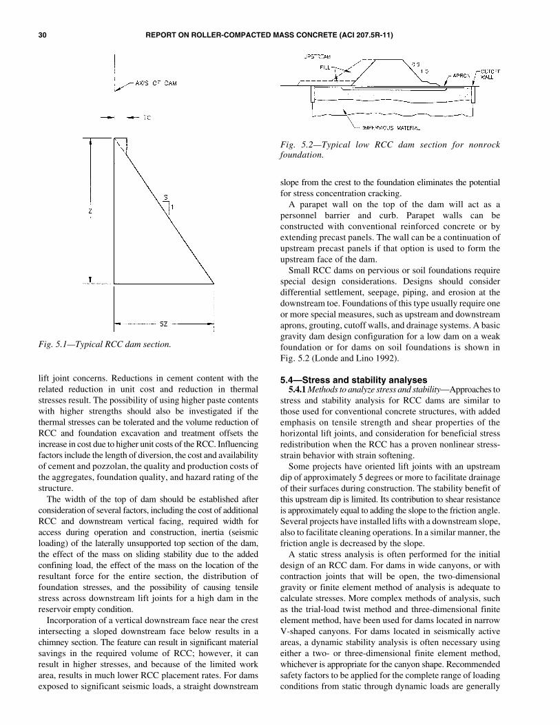
30 REPORT ON ROLLER-COMPACTED MASS CONCRETE (ACI 207.5R-11)
lift joint concerns. Reductions in cement content with therelated reduction in unit cost and reduction in thermalstresses result. The possibility of using higher paste contentswith higher strengths should also be investigated if thethermal stresses can be tolerated and the volume reduction ofRCC and foundation excavation and treatment offsets theincrease in cost due to higher unit costs of the RCC. Influencingfactors include the length of diversion, the cost and availabilityof cement and pozzolan, the quality and production costs ofthe aggregates, foundation quality, and hazard rating of thestructure.
The width of the top of dam should be established afterconsideration of several factors, including the cost of additionalRCC and downstream vertical facing, required width foraccess during operation and construction, inertia (seismicloading) of the laterally unsupported top section of the dam,the effect of the mass on sliding stability due to the addedconfining load, the effect of the mass on the location of theresultant force for the entire section, the distribution offoundation stresses, and the possibility of causing tensilestress across downstream lift joints for a high dam in thereservoir empty condition.
Incorporation of a vertical downstream face near the crestintersecting a sloped downstream face below results in achimney section. The feature can result in significant materialsavings in the required volume of RCC; however, it canresult in higher stresses, and because of the limited workarea, results in much lower RCC placement rates. For damsexposed to significant seismic loads, a straight downstream
slope from the crest to the foundation eliminates the potentialfor stress concentration cracking.
A parapet wall on the top of the dam will act as apersonnel barrier and curb. Parapet walls can beconstructed with conventional reinforced concrete or byextending precast panels. The wall can be a continuation ofupstream precast panels if that option is used to form theupstream face of the dam.
Small RCC dams on pervious or soil foundations requirespecial design considerations. Designs should considerdifferential settlement, seepage, piping, and erosion at thedownstream toe. Foundations of this type usually require oneor more special measures, such as upstream and downstreamaprons, grouting, cutoff walls, and drainage systems. A basicgravity dam design configuration for a low dam on a weakfoundation or for dams on soil foundations is shown inFig. 5.2 (Londe and Lino 1992).
5.4—Stress and stability analyses5.4.1 Methods to analyze stress and stability—Approaches to
stress and stability analysis for RCC dams are similar tothose used for conventional concrete structures, with addedemphasis on tensile strength and shear properties of thehorizontal lift joints, and consideration for beneficial stressredistribution when the RCC has a proven nonlinear stress-strain behavior with strain softening.
Some projects have oriented lift joints with an upstreamdip of approximately 5 degrees or more to facilitate drainageof their surfaces during construction. The stability benefit ofthis upstream dip is limited. Its contribution to shear resistanceis approximately equal to adding the slope to the friction angle.Several projects have installed lifts with a downstream slope,also to facilitate cleaning operations. In a similar manner, thefriction angle is decreased by the slope.
A static stress analysis is often performed for the initialdesign of an RCC dam. For dams in wide canyons, or withcontraction joints that will be open, the two-dimensionalgravity or finite element method of analysis is adequate tocalculate stresses. More complex methods of analysis, suchas the trial-load twist method and three-dimensional finiteelement method, have been used for dams located in narrowV-shaped canyons. For dams located in seismically activeareas, a dynamic stability analysis is often necessary usingeither a two- or three-dimensional finite element method,whichever is appropriate for the canyon shape. Recommendedsafety factors to be applied for the complete range of loadingconditions from static through dynamic loads are generally
Fig. 5.1—Typical RCC dam section.
Fig. 5.2—Typical low RCC dam section for nonrockfoundation.

REPORT ON ROLLER-COMPACTED MASS CONCRETE (ACI 207.5R-11) 31
similar among various international authorities, but they varysomewhat depending on the authority and the thoroughness ofanalysis.
5.4.2 Shear-friction factor—The following discussionrelates to shear within the RCC dam. Shear and stability ofthe foundation should be evaluated as a foundation issue, asit is for traditional concrete dams.
As in a conventional concrete gravity section, resistance tosliding within the RCC section is dependent on the cohesionof the concrete, the compressive stress on the potentialfailure plane, and the coefficient of sliding friction along thefailure plane. Shear through the mass should be considered,especially if there are thinned sections in the mass, such as atan extended toe, but the typical controlling shear plane willbe along the weakest lift joint relative to applied slidingforce, as it is for traditional concrete dams. RCC has manymore lift surfaces than traditional mass concrete, and RCC ismore likely to have low cohesion at the lift surface thantraditionally placed concrete (especially with leaner mixturesand with excessive lift joint maturity), so the probability ofat least some weak lift surfaces can be greater with RCC.This is minimized through proper mixture proportioning,construction equipment and construction procedures, retarders(to prevent forming of a cold joint), and diligent inspection.
The shear-friction factor (SFF) is a measure of the stabilityof a dam against sliding. The SFF on a horizontal plane isexpressed as
SFF = (cA + (N – U)tanφ) /T
where c is the unit cohesion; A is the area of cross section; Nis the component of confining force normal to the slidingsurface; U is the uplift force acting on cross section; φ is theangle of sliding friction; and T is the driving force parallel tothe sliding surface.
The cohesion component of sliding shear resistance alonglift joints is very sensitive to cementitious content andquality, construction quality, rate of placement and set timeof the mixture, and lift joint maturity (Schrader 1999). Bothcohesion and friction resistance are affected by compactionat the lift line, regardless of the cementitious materialscontent and parent strength of the compacted mixture.
Most design criteria require a minimum shear-frictionfactor of safety (SFFS) against sliding of 2 to 4 based onnormal high headwater and low tailwater conditions, from1.5 to 2 under flood conditions, and greater than 1.0 forseismic loads. Although it is not considered by most codesand authorities, a safe criteria for stability of an RCC damis that the factor of safety against sliding greater than 1.0for all load conditions using a cohesion value of zero, anda realistic residual friction angle after sliding, with realisticuplift for unbonded lift joints, should be considered. Precedentsfor this exist, with the most notable being the Saluda Dam(Schrader and Rizzo 2003). The average compacted in-place density at the time of construction is suitable forcomputing the vertical weight.
Shear properties at lift surfaces are dependent on a numberof factors including mixture properties, joint preparation,
time from mixing to compaction, and exposure conditions.Actual values used in final designs should be based on testsof the materials to be used or estimated from tests on RCCmixtures from other projects with similar aggregates,cementitious materials content, aggregate grading, and jointpreparation. As with any dam design, the designer of RCCstructures should be confident that design assumptions arerealistically achievable with the construction conditionsanticipated and the materials available. Joint shear strengthand sample data are discussed more in Chapters 4 and 6, andin various references (Schrader 1999; USACE 1995a; ElectricPower Research Institute 1986; McLean and Pierce 1988;Boggs and Richardson 1985; Tayabji and Okamoto 1987).
For initial planning and design purposes, a value of liftjoint cohesion of 5% of the design compressive strength witha coefficient of friction of 1.0 (corresponding to a φ angle of45 degrees) is generally used. Cohesion tends to be slightlylower for dry consistency RCC mixtures and slightly higherfor wetter consistency mixtures. Where bedding mixture isused, the cohesion value will be essentially the cohesion valueof the unjointed RCC mass. This normally approximates at least10% of the compressive strength of the unjointed RCC.
5.4.3 Determining design values for shear—Designvalues for shear strength parameters at lift joints can bedetermined in several ways. Drilled cores can be removedfrom RCC test placements and tested. Individual specimenscan be laboratory fabricated with simulated lift joints if themixture is of a consistency and the aggregate is of a size thatpermits representative individual samples to be fabricated,but care is needed to realistically correlate laboratory preparedsamples to what will actually be achieved in the field.
At a number of RCC projects, joint shear tests have beenperformed on a series of large blocks of the total RCCmixture cut from test placements compacted with full-scaleequipment or walk-behind rollers that simulate the energy ofa large roller. Various joint maturities and surface conditionsof the actual mixture for the project are evaluated and usedto confirm or modify the design and construction controls.Due to the unique nature of the design criterion, a compre-hensive series of tests was done for Saluda Dam where thedesign was based on residual shear strength after crackingand sliding (Schrader and Rizzo 2003).
In-place direct shear tests have been performed at variousconfining loads on blocks cut into field placements madewith full production equipment and procedures All sheartests for RCC are delicate and unique. They require experiencedpersonnel, special equipment, and special procedures, butin-place tests are probably the most difficult as they requireextra care and attention to detail.
Shear property estimates and shear analyses should takeinto account several key factors:• It is not reasonable that an isolated section of an RCC
dam would slide away, leaving behind another portionof the dam that remains bonded at a lift joint. Conse-quently, over-reaction should be avoided if a finiteelement method analysis indicates that shear stressexceeds shear strength (with appropriate factor ofsafety) for a small portion of a large lift surface;
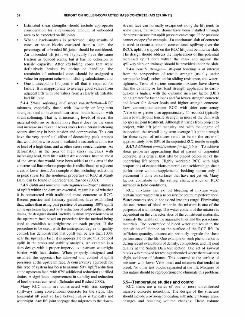
32 REPORT ON ROLLER-COMPACTED MASS CONCRETE (ACI 207.5R-11)
• Estimated shear strengths should include appropriateconsideration for a reasonable amount of unbondedarea to be expected on lift joints;
• When a back-analysis is performed using results ofcores or shear blocks extracted from a dam, thepercentage of unbonded lift joints should be considered.An unbonded lift joint will typically have the samefriction as bonded joints, but it has no cohesion ortensile capacity. After excluding cores that weredefinitively broken by coring or handling, theremainder of unbonded cores should be assigned avalue for apparent cohesion in sliding calculations; and
• One unacceptable lift joint is all that is required forfailure. It is inappropriate to average good values fromadjacent lifts with bad values from a clearly identifiablebad lift joint.
5.4.4 Strain softening and stress redistribution—RCCmixtures, especially those with low-early or long-termstrengths, tend to have nonlinear stress-strain behavior withstrain softening. That is, at increasing levels of stress, thematerial deforms or strains more than it does for the sameunit increase in stress at a lower stress level. Strain softeningoccurs similarly in both tension and compression. This canhave the very beneficial effect of decreasing peak stressesthat would otherwise occur in isolated areas such as at the toeor heel of a high dam, and at other stress concentrations. Asdeformation in the area of high stress increases withincreasing load, very little added stress occurs. Instead, mostof the stress that would have been added to this area if theconcrete had linear elastic properties is redistributed to adjacentareas of lower stress. An example of this, including reductionsin peak stress for the nonlinear properties of RCC at MujibDam, can be found in Schrader and Rashed (2002).
5.4.5 Uplift and upstream watertightness—Proper estimatesof uplift within the dam are essential, regardless of whetherit is constructed with traditional mass concrete or RCC.Recent practice and industry guidelines have establishedthat, rather than using past practice of assuming 100% upliftat the upstream face and 67% reduction of uplift at the drilleddrains, the designer should carefully evaluate imperviousness atthe upstream face based on precedent for the method beingused to establish watertightness on each project. If theprocedure to be used, with the anticipated degree of qualitycontrol, has demonstrated that uplift will be less than 100%near the upstream face, it is appropriate to use this reduceduplift in the stress and stability analysis. An example is adam design with a proper impervious upstream watertightbarrier with face drains. When properly designed andinstalled, this approach has achieved total control of upliftpressures at the upstream face. A conservative approach forthis type of system has been to assume 50% uplift reductionat the upstream face, with 67% additional reduction at drilleddrains. A significant improvement in stability and reductionof heel stresses can result (Schrader and Rashed 2002).
Many RCC dams are constructed with stair-steppedspillways using conventional concrete for the steps. Thehorizontal lift joint surface between steps is typically notwatertight. Any lift joint seepage that migrates to the down-
stream face can normally escape out along the lift joint. Insome cases, half-round drains have been installed throughthe steps to assure that uplift pressure can escape. If the pressurecannot escape (for example, if a continuous slab of concreteis used to create a smooth conventional spillway over theRCC), uplift is trapped on the RCC lift joint behind the slab.The design should address the implications of this potentialincreased uplift both within the mass and against thespillway slab, or drainage should be provided under the slab.
5.4.6 Tensile strength—Lift-joint bonding is of interestfrom the perspectives of tensile strength (usually underearthquake load), cohesion for sliding resistance, and water-tightness. Tests of various concrete mixtures have shownthat the dynamic or fast load strength applicable to earth-quakes is higher, with the dynamic increase factor (DIF)being greater for faster loads and for lower-strength concreteand lower for slower loads and higher-strength concrete.Low cementitious-content RCC with drier consistency(Vebe times greater than approximately 45 seconds) typicallyhas a low lift-joint tensile strength in most of the dam withno special joint treatment. Although it varies from project toproject, with lift joint maturity and with the degree ofinspection, the overall long-term average lift-joint strengthfor these types of mixtures tends to be on the order ofapproximately 30 to 80% of the unjointed RCC tensile strength.
5.4.7 Additional considerations for lift joints—To achieveshear properties approaching that of parent or unjointedconcrete, it is critical that lifts be placed before set of theunderlying lift occurs. Highly workable RCC with highproportions of cementitious materials can achieve high shearperformance without supplemental bedding mortar only ifplacement is done on surfaces that have not yet set. Manyfactors contribute to the setting characteristics of RCCsurfaces in field conditions.
RCC mixtures that exhibit bleeding of mixture watercontain more water than is necessary for optimum performance.Water contents should not extend into this range. Eliminatingthe occurrence of bleed water in the mixture is one of thepurposes of trial mixing. The water content of the mixture isdependent on the characteristics of the constituent materials,primarily the quality of the aggregate fines and the pozzolanicmaterials. The occurrence of bleed water can result in thedeposition of laitance on the surface of the RCC lift. Insufficient quantity, laitance can seriously degrade the shearperformance of the lift. One example of such phenomenon isduring recent evaluations of density, compaction, and lift jointquality at the Saluda Dam test section. One set of saw-cutblocks was removed for testing unbonded where there was justslight evidence of laitance. This occurred at the surface ofmixtures with lower Vebe times and mixtures that tended tobleed. No other test blocks separated at the lift. Mixtures ofthis nature should be reproportioned to eliminate this problem.
5.5—Temperature studies and controlRCC dams are a series of one or more unreinforced
massive concrete monoliths. The design of the structureshould include provisions for dealing with inherent temperaturechanges and resulting volume changes. These volume
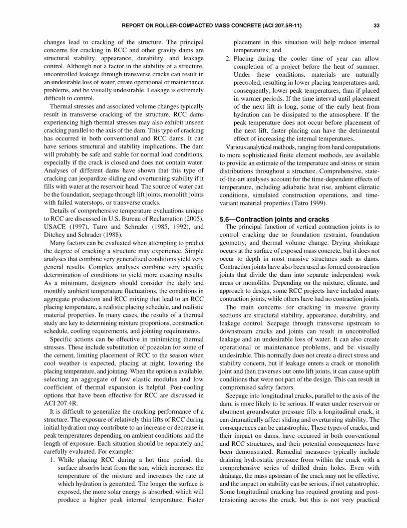
REPORT ON ROLLER-COMPACTED MASS CONCRETE (ACI 207.5R-11) 33
changes lead to cracking of the structure. The principalconcerns for cracking in RCC and other gravity dams arestructural stability, appearance, durability, and leakagecontrol. Although not a factor in the stability of a structure,uncontrolled leakage through transverse cracks can result inan undesirable loss of water, create operational or maintenanceproblems, and be visually undesirable. Leakage is extremelydifficult to control.
Thermal stresses and associated volume changes typicallyresult in transverse cracking of the structure. RCC damsexperiencing high thermal stresses may also exhibit unseencracking parallel to the axis of the dam. This type of crackinghas occurred in both conventional and RCC dams. It canhave serious structural and stability implications. The damwill probably be safe and stable for normal load conditions,especially if the crack is closed and does not contain water.Analyses of different dams have shown that this type ofcracking can jeopardize sliding and overturning stability if itfills with water at the reservoir head. The source of water canbe the foundation, seepage through lift joints, monolith jointswith failed waterstops, or transverse cracks.
Details of comprehensive temperature evaluations uniqueto RCC are discussed in U.S. Bureau of Reclamation (2005),USACE (1997), Tatro and Schrader (1985, 1992), andDitchey and Schrader (1988).
Many factors can be evaluated when attempting to predictthe degree of cracking a structure may experience. Simpleanalyses that combine very generalized conditions yield verygeneral results. Complex analyses combine very specificdetermination of conditions to yield more exacting results.As a minimum, designers should consider the daily andmonthly ambient temperature fluctuations, the conditions inaggregate production and RCC mixing that lead to an RCCplacing temperature, a realistic placing schedule, and realisticmaterial properties. In many cases, the results of a thermalstudy are key to determining mixture proportions, constructionschedule, cooling requirements, and jointing requirements.
Specific actions can be effective in minimizing thermalstresses. These include substitution of pozzolan for some ofthe cement, limiting placement of RCC to the season whencool weather is expected, placing at night, lowering theplacing temperature, and jointing. When the option is available,selecting an aggregate of low elastic modulus and lowcoefficient of thermal expansion is helpful. Post-coolingoptions that have been effective for RCC are discussed inACI 207.4R.
It is difficult to generalize the cracking performance of astructure. The exposure of relatively thin lifts of RCC duringinitial hydration may contribute to an increase or decrease inpeak temperatures depending on ambient conditions and thelength of exposure. Each situation should be separately andcarefully evaluated. For example:
1. While placing RCC during a hot time period, thesurface absorbs heat from the sun, which increases thetemperature of the mixture and increases the rate atwhich hydration is generated. The longer the surface isexposed, the more solar energy is absorbed, which willproduce a higher peak internal temperature. Faster
placement in this situation will help reduce internaltemperatures; and
2. Placing during the cooler time of year can allowcompletion of a project before the heat of summer.Under these conditions, materials are naturallyprecooled, resulting in lower placing temperatures and,consequently, lower peak temperatures, than if placedin warmer periods. If the time interval until placementof the next lift is long, some of the early heat fromhydration can be dissipated to the atmosphere. If thepeak temperature does not occur before placement ofthe next lift, faster placing can have the detrimentaleffect of increasing the internal temperatures.
Various analytical methods, ranging from hand computationsto more sophisticated finite element methods, are availableto provide an estimate of the temperature and stress or straindistributions throughout a structure. Comprehensive, state-of-the-art analyses account for the time-dependent effects oftemperature, including adiabatic heat rise, ambient climaticconditions, simulated construction operations, and time-variant material properties (Tatro 1999).
5.6—Contraction joints and cracksThe principal function of vertical contraction joints is to
control cracking due to foundation restraint, foundationgeometry, and thermal volume change. Drying shrinkageoccurs at the surface of exposed mass concrete, but it does notoccur to depth in most massive structures such as dams.Contraction joints have also been used as formed constructionjoints that divide the dam into separate independent workareas or monoliths. Depending on the mixture, climate, andapproach to design, some RCC projects have included manycontraction joints, while others have had no contraction joints.
The main concerns for cracking in massive gravitysections are structural stability, appearance, durability, andleakage control. Seepage through transverse upstream todownstream cracks and joints can result in uncontrolledleakage and an undesirable loss of water. It can also createoperational or maintenance problems, and be visuallyundesirable. This normally does not create a direct stress andstability concern, but if leakage enters a crack or monolithjoint and then traverses out onto lift joints, it can cause upliftconditions that were not part of the design. This can result incompromised safety factors.
Seepage into longitudinal cracks, parallel to the axis of thedam, is more likely to be serious. If water under reservoir orabutment groundwater pressure fills a longitudinal crack, itcan dramatically affect sliding and overturning stability. Theconsequences can be catastrophic. These types of cracks, andtheir impact on dams, have occurred in both conventionaland RCC structures, and their potential consequences havebeen demonstrated. Remedial measures typically includedraining hydrostatic pressure from within the crack with acomprehensive series of drilled drain holes. Even withdrainage, the mass upstream of the crack may not be effective,and the impact on stability can be serious, if not catastrophic.Some longitudinal cracking has required grouting and post-tensioning across the crack, but this is not very practical
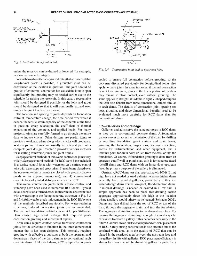
34 REPORT ON ROLLER-COMPACTED MASS CONCRETE (ACI 207.5R-11)
unless the reservoir can be drained or lowered (for example,in a navigation lock outage).
When thermal or other analysis indicates that an unacceptablelongitudinal crack is possible, a groutable joint can beconstructed at the location in question. The joint should begrouted after thermal contraction has caused the joint to opensignificantly, but grouting may be needed earlier due to theschedule for raising the reservoir. In this case, a regroutablejoint should be designed if possible, or the joint and groutshould be designed so that it will continually expand overtime as the joint tends to open more.
The location and spacing of joints depends on foundationrestraint, temperature change, the time period over which itoccurs, the tensile strain capacity of the concrete at the timein question, creep relaxation, the coefficient of thermalexpansion of the concrete, and applied loads. For manyprojects, joints are carefully formed to go through the entiredam to induce cracks. Other designs use partial joints toprovide a weakened plane along which cracks will propagate.Waterstops and drains are usually an integral part of acomplete joint design. Chapter 6 provides various methodsfor installing transverse joints and joint drains.
Seepage control methods of transverse contraction joints varywidely. Seepage control methods for RCC dams have included:1) a surface control joint with waterstop; 2) a surface controljoint with waterstops and grout taken; 3) membrane placed overthe upstream (either a membrane placed with precast concreteponds or an exposed membrane); and 4) conventionalconcrete face of jointed slabs placed after the RCC.
Transverse contraction joints with surface control andwaterstop have been used in numerous RCC dams. Typicaldetails consist of a formed crack inducer in the upstream facewith a waterstop in the facing concrete, as shown in Fig. 5.3and 5.4, followed by crack inducement in the RCC lift by oneof the methods described previously. For water-retainingstructures, induced contraction joints are recommended.Thermal and foundation related cracks at Upper StillwaterDam caused significant leakage that required post-construction grouting and subsequent repairs.
Arch dams require contact across transverse contractionjoints for the structure to function in the three-dimensionalmanner that is has been designed. This normally requiresgrouting with effective grout stops at both the upstream anddownstream faces of the dam, similar to conventional archconcrete dams. Unlike arch dams, RCC is typically not post-
cooled to ensure full contraction before grouting, so theconcerns discussed previously for longitudinal joints alsoapply to these joints. In some instances, if thermal contractionis kept to a minimum, joints in the lower portion of the dammay remain in close contact, even without grouting. Thesame applies to straight-axis dams in tight V-shaped canyonsthat can also benefit from three-dimensional effects similarto arch dams. The details of contraction joint opening (ornot), grouting, and three-dimensional benefits need to beevaluated much more carefully for RCC dams than forconventional dams.
5.7—Galleries and drainageGalleries and adits serve the same purposes in RCC dams
as they do in conventional concrete dams. A foundationgallery serves as access to the interior of the dam for drillingor redrilling foundation grout curtain and drain holes,grouting the foundation, inspections, seepage collection,access for instrumentation and other equipment, and aterminal point for drain holes drilled from the crest or into thefoundation. Of course, if foundation grouting is done from anupstream cutoff wall or plinth slab, as it is for concrete-facedrockfill dams and RCC dams with an impervious upstreamface, the primary purpose of the gallery is eliminated.
Generally, RCC dams less than approximately 100 ft (31 m)high have not needed or used galleries, whereas higher damsgenerally have included galleries, particularly if they arewater-storage dams versus low-pool, flood-retention dams.If internal drainage is needed or desired in a low dam, asimple approach has been to place free-draining coarseaggregate approximately three lifts high at the locationwhere a gallery would otherwise be located (Schrader 2002).Drains are then drilled from the top of RCC or top of thedam, through the aggregate drain, and into the foundation.The aggregate drain discharges to the downstream face. Bymaking the aggregate drain large enough, it can always beexcavated to create a gallery if this becomes necessary in thefuture. Galleries are an obstacle to rapid and efficient placementof RCC. Safety during construction is also affected due to theconfined work area, as is the quality of RCC that can beplaced in the restricted area between the upstream face andthe gallery. In lifts with galleries, RCC placement efficiency isalways less than it would be absent the gallery. In particularly
Fig. 5.3—Contraction joint detail.
Fig. 5.4—Contraction joint seal at upstream face.
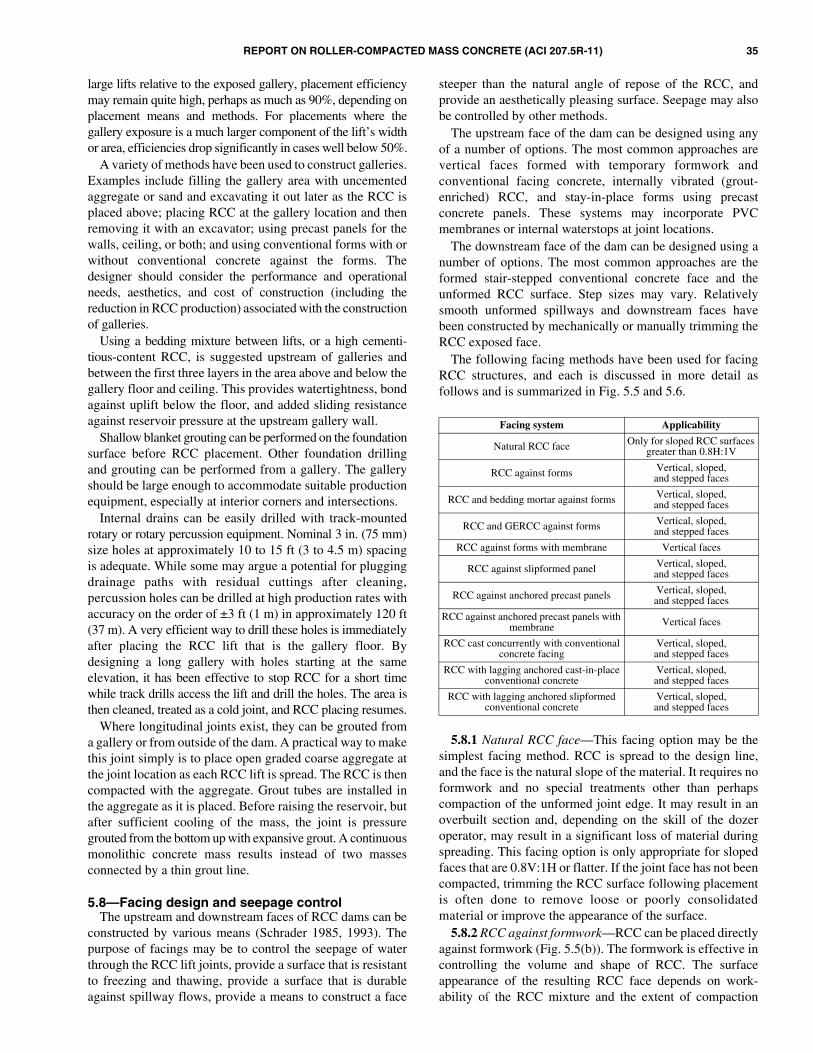
REPORT ON ROLLER-COMPACTED MASS CONCRETE (ACI 207.5R-11) 35
large lifts relative to the exposed gallery, placement efficiencymay remain quite high, perhaps as much as 90%, depending onplacement means and methods. For placements where thegallery exposure is a much larger component of the lift’s widthor area, efficiencies drop significantly in cases well below 50%.
A variety of methods have been used to construct galleries.Examples include filling the gallery area with uncementedaggregate or sand and excavating it out later as the RCC isplaced above; placing RCC at the gallery location and thenremoving it with an excavator; using precast panels for thewalls, ceiling, or both; and using conventional forms with orwithout conventional concrete against the forms. Thedesigner should consider the performance and operationalneeds, aesthetics, and cost of construction (including thereduction in RCC production) associated with the constructionof galleries.
Using a bedding mixture between lifts, or a high cementi-tious-content RCC, is suggested upstream of galleries andbetween the first three layers in the area above and below thegallery floor and ceiling. This provides watertightness, bondagainst uplift below the floor, and added sliding resistanceagainst reservoir pressure at the upstream gallery wall.
Shallow blanket grouting can be performed on the foundationsurface before RCC placement. Other foundation drillingand grouting can be performed from a gallery. The galleryshould be large enough to accommodate suitable productionequipment, especially at interior corners and intersections.
Internal drains can be easily drilled with track-mountedrotary or rotary percussion equipment. Nominal 3 in. (75 mm)size holes at approximately 10 to 15 ft (3 to 4.5 m) spacingis adequate. While some may argue a potential for pluggingdrainage paths with residual cuttings after cleaning,percussion holes can be drilled at high production rates withaccuracy on the order of ±3 ft (1 m) in approximately 120 ft(37 m). A very efficient way to drill these holes is immediatelyafter placing the RCC lift that is the gallery floor. Bydesigning a long gallery with holes starting at the sameelevation, it has been effective to stop RCC for a short timewhile track drills access the lift and drill the holes. The area isthen cleaned, treated as a cold joint, and RCC placing resumes.
Where longitudinal joints exist, they can be grouted froma gallery or from outside of the dam. A practical way to makethis joint simply is to place open graded coarse aggregate atthe joint location as each RCC lift is spread. The RCC is thencompacted with the aggregate. Grout tubes are installed inthe aggregate as it is placed. Before raising the reservoir, butafter sufficient cooling of the mass, the joint is pressuregrouted from the bottom up with expansive grout. A continuousmonolithic concrete mass results instead of two massesconnected by a thin grout line.
5.8—Facing design and seepage controlThe upstream and downstream faces of RCC dams can be
constructed by various means (Schrader 1985, 1993). Thepurpose of facings may be to control the seepage of waterthrough the RCC lift joints, provide a surface that is resistantto freezing and thawing, provide a surface that is durableagainst spillway flows, provide a means to construct a face
steeper than the natural angle of repose of the RCC, andprovide an aesthetically pleasing surface. Seepage may alsobe controlled by other methods.
The upstream face of the dam can be designed using anyof a number of options. The most common approaches arevertical faces formed with temporary formwork andconventional facing concrete, internally vibrated (grout-enriched) RCC, and stay-in-place forms using precastconcrete panels. These systems may incorporate PVCmembranes or internal waterstops at joint locations.
The downstream face of the dam can be designed using anumber of options. The most common approaches are theformed stair-stepped conventional concrete face and theunformed RCC surface. Step sizes may vary. Relativelysmooth unformed spillways and downstream faces havebeen constructed by mechanically or manually trimming theRCC exposed face.
The following facing methods have been used for facingRCC structures, and each is discussed in more detail asfollows and is summarized in Fig. 5.5 and 5.6.
5.8.1 Natural RCC face—This facing option may be thesimplest facing method. RCC is spread to the design line,and the face is the natural slope of the material. It requires noformwork and no special treatments other than perhapscompaction of the unformed joint edge. It may result in anoverbuilt section and, depending on the skill of the dozeroperator, may result in a significant loss of material duringspreading. This facing option is only appropriate for slopedfaces that are 0.8V:1H or flatter. If the joint face has not beencompacted, trimming the RCC surface following placementis often done to remove loose or poorly consolidatedmaterial or improve the appearance of the surface.
5.8.2 RCC against formwork—RCC can be placed directlyagainst formwork (Fig. 5.5(b)). The formwork is effective incontrolling the volume and shape of RCC. The surfaceappearance of the resulting RCC face depends on work-ability of the RCC mixture and the extent of compaction
Facing system Applicability
Natural RCC face Only for sloped RCC surfaces greater than 0.8H:1V
RCC against forms Vertical, sloped,and stepped faces
RCC and bedding mortar against forms Vertical, sloped,and stepped faces
RCC and GERCC against forms Vertical, sloped,and stepped faces
RCC against forms with membrane Vertical faces
RCC against slipformed panel Vertical, sloped,and stepped faces
RCC against anchored precast panels Vertical, sloped,and stepped faces
RCC against anchored precast panels with membrane Vertical faces
RCC cast concurrently with conventional concrete facing
Vertical, sloped,and stepped faces
RCC with lagging anchored cast-in-place conventional concrete
Vertical, sloped,and stepped faces
RCC with lagging anchored slipformed conventional concrete
Vertical, sloped,and stepped faces

36 REPORT ON ROLLER-COMPACTED MASS CONCRETE (ACI 207.5R-11)
effort near the form surface. Excellent results have beenachieved on several projects. Unfortunately, sufficient careis not usually taken in the placement of this system, and it isgenerally prone to poor appearance. The freezing-and-thawingresistance of this system is not good, and should only be usedin protected areas or temperate climates. Form movement isa concern when placing RCC directly against external formingsystems unless it is grout enriched and internally vibrated.
5.8.3 RCC and bedding mortar against forms—The additionof bedding mortar between the RCC and against the formsurface provides several improvements. It provides a barrierto water that may seep along a lift surface that is inadequatelycompacted or has accumulated segregated aggregate. Thebedding mortar fills voids at the form surface, resulting in amore conventional concrete appearance. The resultingappearance can be good. The freezing-and-thawing resistanceof this system is not good, and should only be used inprotected areas or in temperate climates.
5.8.4 RCC with GERCC against forms—When cementgrout is placed in sufficient quantity on the RCC surfacealong the formed face and the RCC is of sufficient workability,it is possible that the affected area can be consolidated withinternal vibrators. This is termed grout-enriched roller-
compacted concrete (GERCC). The practice varies fromplacing grout on the previous lift and covering with freshRCC, placing the fresh RCC with the grout on top, or both.The goal is to place a sufficient quantity of high-qualitygrout to modify the no-slump RCC to a consistency suitablefor internal vibrators. This system results in a very goodsurface appearance with less placement impacts than placingconventional concrete at the face. The freezing-and-thawingresistance of this system is not good, and should only be usedin protected areas or temperate climates.
5.8.5 RCC against forms with membrane—The previousfacing systems can be further modified to include a PVCmembrane. Membranes have been installed on the verticalformwork surfaces against which RCC is placed. The formsare removed and the membrane is left in place. It is morecommon, and often more practical, to install such amembrane after the RCC has been placed to avoid productionimpacts of concurrent membrane installation.
5.8.6 RCC against slipformed concrete element—Interlocking slipformed stay-in-place elements have beenused to create a permanent face (Fig. 5.5(e)). Slipformedconcrete has been used on several projects to provide a high-quality concrete facing cast hours ahead of the RCCplacement. After several hours, the interlocking curbelements are strong enough to serve as a form for the RCCyet young enough to maximize the bond between the RCCand the curb element. This system is ideal for projects wherelong continuous placements allow a slipform operation tomove efficiently and where the rate of rise of RCC structureis approximately 3 ft (1 m) or less per day and does notoverwhelm the slipform operation.
5.8.7 RCC against anchored precast panels—Anotherstay-in-place forming system uses precast concrete panels asforms (Fig. 5.5(f)). The precast concrete panels are placedand braced with either external form supports or bracedagainst adjacent staggered panels. The latter system candepend on tieback anchors to provide the lateral stability. Allprecast panel systems use internal anchors as the permanentmeans to attach the panels to the RCC.
5.8.8 RCC against anchored precast panels withmembrane—Precast panels make an attractive, economical,and crack-free face, but the panel joints are not watertight(Fig. 5.5(f)). Watertightness has been provided with amembrane of polyvinyl chloride (PVC) or polyethyleneattached to the back of each panel. A pressure connectionwith epoxy has been used to provide a watertight seal wherethe anchors penetrate the membrane. The joints betweenpanels need to be heat-welded to produce the impermeableface. Drains can be installed in the RCC to collect seepage.
There are two documented cases in the U.S. (Penn ForestDam and Hunting Run Dam) where panels with attachedmembranes failed during construction. Rain, curing water, ora combination of both seeped between the membrane and theRCC. The hydrostatic pressures caused the panel anchor rodinserts to fail, allowing the panel to move away from the damand thereby rupturing the membrane. Paradise Dam(formally Burnett Dam) in Australia had panel damageduring a drawdown of the reservoir.
Fig. 5.5—Upstream facing options.
Fig. 5.6—Downstream facing options.
REPORT ON ROLLER-COMPACTED MASS CONCRETE (ACI 207.5R-11) 37
5.8.9 RCC cast concurrently with consolidated concretefacing—If a conventional concrete appearance or addeddurability is desired, conventional concrete can be used forthe facing (Fig. 5.5(c) and (d)). A common method ofconstructing a conventional concrete face is to concurrentlyplace the RCC with the facing concrete. No anchors orreinforcement other than that necessary to stabilize form-work are used to anchor the facing concrete to the RCC(Fig. 5.5(c)). Crack control of the facing mixture can beprovided by water-stopped or sealed vertical contraction jointsspaced appropriately for the mixture and exposure conditions.Typically, this is approximately every 16 to 30 ft (5 to 10 m).The thickness, or width (upstream to downstream), of aconventional concrete face varies from 1 to 3 ft (0.3 to 0.9 m).For thicker facings, the designer should consider the effect theextra mass has on temperatures, thermal contraction of the RCCand facing, and the contraction joint spacing.
5.8.10 RCC with lagging anchored cast-in-place concrete—Figure 5.5(a) and (b) are reinforced conventional concretefacings placed after the RCC has been placed. This is similarin concept to the concrete facing on the sloped face of a rock-fill dam. Because of its typically high estimated cost andextended construction time, this facing method has not beenfrequently used. It has, however, been used at Stacy andLake Alan Henry Dams.
5.8.11 RCC with lagging anchored cast-in-placeconcrete—A modification of Fig. 5.5(c) and 5.6(c) uses atemporary blockout at the face for every other lift (Fig. 5.5(d)and 5.6(d)). The blockout is removed before placing theconventional facing and the next RCC lift. Added watertight-ness can be achieved by using a simple swelling-strip water-stop that is impregnated with chemical grout. It is placed alongthe lift surfaces of the facing concrete. If seepage occurs, themoisture causes the strip to swell and create a watertightpressure seal against the adjacent lift surface.
5.8.12 RCC with lagging anchored slipformed concrete—Slipformed concrete with anchors and two-way reinforcement,placed after completion of the RCC, is shown in Fig. 5.6(g)and is suitable as a flow surface.
The aforementioned systems use a variety of measures tocontrol potential seepage through the RCC lifts. Internalmeasures include mixture proportions that contain anabundance of paste so that bonding along the lift surface isimproved. Regardless of what facing design or seepagecontrol measures are selected, good bond is essential at thelift joint and at the interface between the dam and thefoundation. External measures include a number of featuresdiscussed herein.• The seepage control measures used for particular facing
systems can be used for most of the other facingsystems. Drains can be installed between the membraneand RCC;
• The use of bedding mixture between the lifts cansubstantially improve watertightness and bond alonghorizontal lift joints. This practice has become the morecommon approach to reducing seepage at lift joints;
• Added watertightness can be achieved by using asimple swelling strip waterstop that is impregnated
with chemical grout. It is laid along the facing mixturelift surface. If seepage penetrates the lift joint, moisturecauses the strip to swell and create a watertight pressureseal against the adjacent lift surfaces; and
• Another approach for RCC dams is to attach themembrane to the face of the dam with external profilesthat also serve as a drain system to relieve uplift pressureat the face. The membrane is a special formulation ofPVC, usually 0.08 in. (2 mm) thick, that is resistant toexposure and ultraviolet light. It resists puncture anddamage from ice and floating debris. Concerns fordamage due to vandalism can be overcome withvarious simple methods to prevent cutting and removalof a sheet of the membrane, but this concern has notbeen a real problem at the projects in service. Whenproperly designed with appropriate materials andinstalled by specialists, this proprietary membranesystem has essentially provided total watertightnessregardless of the cement content, cold joint criteria,construction method, and mixture proportions. Its successhas been one of the reasons for using it to stop leakageat cracks that have become a problem from the surfaceof the dam, if necessary. In addition to watertightness,one of the reasons for using the membrane and facedrain system is that it also relieves uplift pressure at theface of the dam, rather than allowing it to enter thebody of the dam. Relying on the mass of the RCC itselfand watertightness of lift joints requires a reduction ofstability due to full uplift at the face, decreasing to somelesser value within the dam depending on internal drainage.
Using a wetter consistency, high cementitious-contentmixture (typically with a high percentage of fly ash and alarge dosage of retarder), and cooling properly, can result indramatically better lift joint bond and watertightnesscompared with more economical mixtures with lowercementitious content, drier consistency, little or no cooling,and no admixture. When done properly, these mixturesgenerally provide lift joint quality similar to traditional massconcrete lift joints. That is, they are essentially watertight,with occasional instances of seepage. This is not guaranteedthough. It is normal to expect some seepage at some liftjoints, just as it typically occurs for conventional massconcrete dams.
5.9—Spillways, aprons, and stilling basinsTraditional spillway designs used for conventional
concrete dams are also appropriate for RCC dams. Gatedspillways that include controls, support piers, and spillwaychutes, constructed of both reinforced and unreinforcedconcrete, have been incorporated into RCC structures.Conventional stepped spillways are very common, althoughsmooth spillways are also used. Because erosion resistanceof RCC is exceptionally good, unformed spillway surfaces,having the rough textured appearance of the RCC placement,have also been used for low-head spillways or spillwayssubject to infrequent use (Schrader and Stefanakos 1995).Typically, the rough unformed RCC surface in these spillways
38 REPORT ON ROLLER-COMPACTED MASS CONCRETE (ACI 207.5R-11)
is trimmed back to sound material, with major abruptirregularities being removed.
For low spillway discharge situations, the spillway andoutlet may be combined. The primary spillway and outletworks at Middle Fork Dam were combined in a double-chambered tower placed against the upstream face andconnected to conduits in a trench at the maximum sectionleading to the control structure at the toe (Parent et al. 1985).The conduits were constructed before RCC placement, thusavoiding interference with RCC placing operations.
Spillways with conventional concrete steps have becomevery common in RCC dams (Campbell and Johnson 1984).They are relatively economical, and because they can beconstructed lift by lift with the RCC or as a separate activitytrailing RCC placement that is at some higher elevation, theycan save time on the overall construction schedule. Steps canalso be placed after all RCC is completed, similar to mostsmooth spillway facings. The steps should be some convenientmultiple of the lift height, with two lifts being most common.This is dictated partially by construction forming andconvenience, but primarily by hydraulic design. Larger unitdischarges require larger steps. Stepped spillways candissipate substantial energy, thereby significantly reducingstilling basin requirements for low and moderate unitdischarges. Steps that are up to several lifts high are noteffective for large unit discharges, but larger steps have beenmodeled and used for these conditions. A notable featureapplied to Littlerock Dam in California was a 6 ft (1.8 m)downstream step height used to lessen the likelihood ofpedestrians climbing the downstream face (McDonald andCurtis 1997). If steps are kept at a nominal height on theorder of 2 to 3 ft (600 to 900 mm), and they are effective forall except extreme floods, the steps will still pass the floodflow. The steps will simply create a boundary layer of low-velocity turbulent flow, with the mass of high-velocity waterflowing over this protective layer. The owner should becontent to accept the occasion duration and frequency offlow where energy is not effectively dissipated by the steps,such as at Buckhorn Dam.
Stepped spillways have been constructed with almost noreinforcement and with substantial reinforcement, all withgood success. Reinforcing does not add to cavitation orerosion resistance. Its purpose is to connect the conventionalfacing concrete to anchors placed in the RCC mass, and tocontrol the width of drying shrinkage cracks in the conventionalconcrete. If the facing mixture has minimal shrinkage andcontraction joints, reinforcing has been as minimal as justtwo longitudinal bars tied to the anchors. Contraction jointswith no continuous reinforcement should be placed at allmonoliths in the RCC mass. Primarily for aesthetic reasons,intermediate contraction joints are normally placed atapproximately 6 to 12 ft (2 to 4 m) spacing, typically withhalf the reinforcement being continuous through the joint.Anchorage for stepped spillways is primarily a judgmentaldesign with a wide range. Typically, two anchors are usedfor each step height and contraction joint spacing, but thereare many variations. The tendency is to have less anchorage
when the facing concrete is placed concurrently with, or verysoon after, the RCC.
As with stepped spillways, smooth conventional concreteslabs placed over RCC have had a wide range of judgmentalanchoring systems, but always with more concern than forstepped spillways. In addition to uplift pressure frompotential leaking lift joints that is trapped by the slab, theslab can also be subjected to negative pressures from high-velocity surface flows. The slab is typically designed withwaterstops to prevent velocity head from getting under theslab at construction joints. Reinforcing steel is typicallydesigned by a combination of judgment, structural design forthe slab being supported by the anchors, and reinforcementto keep shrinkage cracks small enough to prevent velocityhead from penetrating.
The Copperfield Dam has been in service for 20 years withroutine small discharges and occasional major floods withhigh velocities. It has a smooth spillway surface that wasconstructed by placing low-shrinkage conventional concretelift by lift with the RCC, and compacting the RCC into thefresh concrete. The spillway has no contraction joints, noreinforcement, and no anchors. It required extreme qualitycontrol during construction and the practice has not beenreadily adopted.
RCC has also been used to construct anchored and reinforcedstilling basin slabs and aprons. Willow Creek, Buckhorn,Burton Gorge, and Burnett River Dams are examples.Reinforcement is typically placed only in the top slab, whichnormally has a higher strength on the order of 3000 to 5000 psi(21 to 35 MPa). The maximum aggregate size is typically1 to 1-1/2 in. (25.0 to 37.5 mm).
5.10—Outlet worksOutlet structures and conduits can provide obstacles to
RCC placement. The preferred practice in placement of outletworks in RCC design is to locate the conduits in or along therock foundation to minimize delays in RCC placement.
Conduits are usually constructed of concrete-encased steelpipe or conventional concrete before initiating RCC place-ment. Locating the intake structure upstream of the dam andcontrol house and the energy dissipator downstream of thetoe also minimizes interference with RCC placement. Whileused, the avoidance of large embedments in the dam cansimplify the construction, minimize schedule impacts, andmaximize savings. The conduits are usually installed intrenches beneath the dam or along an abutment. It maysometimes be possible or even necessary to route outletsthrough diversion tunnels. In situations where conditionsdictate that waterways must pass through the dam, thepreferred approach is to locate all of the penetrations in oneconventionally placed concrete block before starting theRCC placements; this permits proper cooling of theconventional concrete and eliminates interface problemsbetween the RCC and conventional concrete.
Some RCC flood-control projects have combined oneconduit to serve the purpose of a passageway or roadwaythrough the dam for normal conditions, and to act as an

REPORT ON ROLLER-COMPACTED MASS CONCRETE (ACI 207.5R-11) 39
ungated outlet during floods (Schrader 2002; Schrader andBalli 2003).
CHAPTER 6—CONSTRUCTION OFROLLER-COMPACTED CONCRETE DAMS
6.1—GeneralThe layout, planning, and logistics for construction with
RCC are somewhat different than for conventional massconcrete construction. Instead of vertical construction withindependent monolith blocks, RCC construction involvesplacing relatively thin lifts over a large area. Conventionalmass concrete placement usually requires a high ratio oflabor hours to volume placed due to labor-intensive activi-ties, such as forming faces, joint preparation, and consoli-dating concrete with internal vibrators. RCC typically has alower ratio of labor hours to volume placed because of theuse of mechanical equipment for spreading and compactingthe mixture, less forming, and reduced joint cleanup. Morelabor and attention is required to provide wet curing for RCCbecause membrane-forming curing compounds are prohibiteddue to their adverse effects on lift joints.
Recent trends in RCC construction have centered ondeveloping equipment and methods for placing multiple liftsof RCC quickly, before the concrete has reached its initialset. This improves the bonding between successive lifts anddecreases the cost of cleaning lift surfaces and placing costlybonding mortar. Intensive lift surface preparation candecrease the RCC placing rate by up to 50%. The trend torapid lift placing has been fueled by the construction of muchlarger RCC dams in the last decade and more accepted use ofretarding admixtures to delay the setting time of the concreteuntil after the next lift is placed. Rapid placing rates shouldalso be accompanied by new methods of constructing theupstream and downstream faces of the dams and handlingand cooling the concrete. The sloping layer method ofplacing RCC and the development of GERCC facing are twoconstruction innovations that have markedly increased theability to rapidly place successive lifts of RCC withoutaffecting the forming progress.
With the rapid construction progress typical of RCCplacement, when problems develop in the placing area, theyshould be resolved quickly. There usually are no alternatemonolith blocks in RCC construction where work can progresswhile a problem is resolved. Raising a portion of the placingarea ahead of the problem area has been done, but it can laterresult in placing difficulties and potential planes of weakness.Planning and preparation of materials, access, embeddedparts, and foundation and lift cleanup before the start of RCCplacement are essential. It is also essential that lines ofcommunication between the engineer and contractor be well-established so that they can quickly resolve problems andspecification compliance issues that may impact the progressof the work. Interruptions and slowdowns generally causereduced joint and RCC quality, as well as increased costs.
Impediments to placement and compaction rates canreduce the RCC quality. Equipment, fueling, formwork, andassembly of embedded items should all be scheduled andplanned so that the majority of this work is accomplished off
the RCC surfaces and during shift changes or scheduleddowntime. All unnecessary vehicles and personnel should bekept out of placing areas and equipment paths.
The inter-relationship between design assumptions andconstruction methods has a significant effect on the successof the project. Successful construction of RCC dams isachieved by selecting equipment and plant systems withproduction rates to match the design assumptions and speci-fications requirements. This includes selecting an RCCproduction and placement rate and forming system for theupstream and downstream faces of the dam and matches theanticipated rate of rise of the dam to meet lift surface bondstrength requirements. A common problem occurs wheninevitable production breakdowns or slowdowns invokestringent specifications requirements for lift surface treatment,which reduces the placement rate. The reduced placementrate for lift surface treatment can again cascade and invokethe same lift surface treatment requirements, causing furtherdelays in production. Arguably, the most successful RCCprojects have been built with production and deliverysystems that very rarely are the controlling productionfeatures. An example is Stagecoach Dam, where the 150 ft(46 m) dam was placed in 35 production days, averagingbetter than four lifts per day, including gallery construction,drain-hole drilling, cast-in-place facings, and an intentionalspillway break (Arnold and Johnson 1992). Above thegallery and below the spillway break, 60 lifts were placed in10 days, production being limited by face forming procedures(the plant and delivery capacity was never the controllingfactor). Achievable plant capacity was in excess of 250 yd3
(190 m3) per hour, yet the overall project average per shift hourwas less than 100 yd3 (76 m3) per hour. While this was not oftenchallenged, the RCC was available whenever needed.
6.2—Aggregate production and batching and mixing plant location
Aggregate stockpiles and the concrete plant location forRCC can be even more important than for conventionalconcrete. Typically, large stockpiles are provided beforestarting RCC placement. Reasons for this include:
1. Temperature control: producing aggregates during thewinter (or summer) so that they are stockpiled cold (orwarm) for later use—When the aggregates are producedduring cool (or warm) weather, there is a temperature lagbetween the concrete placing temperature and the ambienttemperature. Rapid RCC placement following aggregatestockpiling can result in concrete temperatures severaldegrees lower (or higher) than ambient temperatures. AtMiddle Fork and Stagecoach Dams in Colorado, GrindstoneCanyon Dam in New Mexico, and Monksville Dam in NewJersey, winter stockpiling resulted in aggregates withoccasional frozen zones in the stockpiles, remaining as lateas late May. At Burton Gorge Dam in Australia, instrumentationshowed that production of RCC aggregate at night resulted ina 9°F (5°C) lower aggregate stockpile temperature than similaraggregates produced during the day.
40 REPORT ON ROLLER-COMPACTED MASS CONCRETE (ACI 207.5R-11)
2. Rapid placement rate—The rate of aggregate use duringRCC placing may exceed the capacity of an aggregateproduction plant.
3. Aggregate stockpile moisture—Large aggregatestockpiles also have the benefit of more stable moisturecontents, which reduces variations in RCC consistency.
The location and configuration of stockpiles, as well as themeans of aggregate and withdrawal from stockpiles, must becoordinated with the RCC plant location and method of feedto minimize segregation and variability. At the very highproduction rates possible with RCC, several loaders or aconveyor system may be required to keep the aggregate feedbins charged. The length of haul and size of turnaroundsneed to be considered so that transportation equipment canoperate rapidly, efficiently, and safely. If a rewashing/rescreening plant is required at the batching plant, the plantrate is frequently reduced by the aggregate feed and screenrate and may be further reduced if the screens become over-loaded or the aggregate gradation is highly variable.
Inadequate cementitious material delivery and storage haslimited RCC production on some projects. A steady flow ofthese materials is necessary for optimum production andconsistent RCC quality.
The RCC plant layout and location should be selected tominimize energy requirements and be appropriate for theterrain, whether the RCC is transported by conveyor or byhaul vehicles. The location should minimize overall hauldistances, vertical lift, and exposure of the fresh mixture tosun and inclement weather. The plant should be located on araised area and graded so that spillage and wash water drainaway without creating a muddy area, especially if vehicularhaul is used. The plant location for dams will generally be inthe future reservoir area and above the cofferdam level, or onone of the abutments. A plant location adjacent to the RCCstructure minimizes transport time, which is critical to RCCquality, and reduces transport equipment needs. The plantshould have a bypass or belt discharge that allows for wastingout-of-specification RCC without delivering it to the dam.
6.3—Batching and mixing6.3.1 General—The RCC method changes the production-
controlling elements of mass concrete placements, from therate of placement for conventional mass concrete to theoutput of the concrete plant and delivery system for RCC.Recent trends include the development of batching andmixing plants specifically for RCC construction rather thanmodified conventional plants. This includes more sophisticatedcontrols for both continuous volumetric and continuousweighing plants with the ability to batch admixtures and useof twin-shaft compulsory mixers. Batching can be achievedby conventional weigh-batching, continuous weigh-batchingusing belt scales, and continuous volumetric batching witheither vane feeders or cleated belt feeders. Mixing has beenaccomplished by conventional drum mixers, continuouspugmills, or batched twin-shaft compulsory mixers.
Rapid and continuous delivery of RCC is important tomass applications. The theoretical, or rated, peak capacity ofthe plant is invariably well above the desired average
production. As a general guide, the average sustainedplacing rate does not usually exceed approximately 65% ofthe peak or rated plant capacity when haul vehicles are usedfor delivery on the dam, and 75% when conveyor andhauling vehicles or an all-conveyor delivery system is used.These values tend to be lower on smaller projects and higheron uncomplicated or larger projects.
RCC mixers should accomplish two basic functions: tothoroughly blend all ingredients and to provide sufficientcapacity for high placing rates typical in RCC. Typicalplacing rates are 100 yd3/h (76 m3/h) for small projects, 250to 500 yd3/h (190 to 380 m3/h) for medium projects, and750 to over 1000 yd3/h (570 to over 760 m3/h) for largeprojects. Several individual mixers are used to provide thehigher production rates. Scheduled maintenance should notbe neglected, and repairs should be accomplished rapidly tominimize downtime.
Batching controls should be calibrated for the lowerquantities of cementitious materials common with RCC. Forexample, a typical 2% tolerance for a 10 yd3 (7.5 m3) batchof conventional concrete is 120 lb (55 kg), whereas for atypical RCC batch, the same 2% tolerance may be only 25 lb(11 kg) each for cement and pozzolan, and may be beyondthe scale tolerances of some concrete batching plants.
Variations in free moisture content of the aggregates canbe particularly troublesome at plant startup. Providing toolittle water in the initial mixtures is particularly undesirablebecause initial mixtures are frequently used for coveringconstruction joints or foundation areas where the RCCshould be on the wet side for improved workability andbond. It is better to start with higher moisture content and tosubsequently reduce it to the desired consistency than to startwith a mixture that is too dry. RCC placed with a higher-than-optimum moisture content is typically more dense andhas lower air voids and permeability. Care must be taken toavoid an overly wet mixture, which reduces the RCCstrength. Variability in moisture content significantly affectsthe quality of the RCC.
Accurately introducing the specified quantities of materialsinto a mixer is only one part of the mixing process.Uniformly distributing and thoroughly blending materials,and discharging them in a continuous and uniform mannerare also essential for providing quality RCC. Distributingand blending can be more troublesome with some RCCmixtures than with conventional concrete mixtures becauseof the lower unit water content in the RCC mixtures.
Both continuous mixers and batch mixers have been usedto produce RCC. Continuous mixers generally providehigher output capacity than batch-type plants. Continuouspugmill mixing plants that are specifically intended for RCCand are properly operated and maintained, routinely achievethe high production rates and uniformity required for massplacements. This applies to plants that operate with volumetriccontrols, as well as those that operate on weight controls.Operation of drum mixers requires less power than pugmillmixers. Batch operations with drum mixers tend to cause themost difficulties or concerns in producing RCC, as discussed

REPORT ON ROLLER-COMPACTED MASS CONCRETE (ACI 207.5R-11) 41
in Section 6.3.2. Traditional batch plants may be needed forbatching conventional concrete associated with the project.
6.3.2 Batching and drum mixing methods—RCC has beensuccessfully produced with conventional batch type plantsand drum mixers. Lower production, bulking, sensitivity tothe charging sequence, slow discharge, and buildup in themixer are common problems in RCC production comparedwith batching of conventional plant and transit-mixedconcrete. Equipment that is well-suited to normal high-production conventional concrete is not necessarily suitablefor all RCC mixtures and the typically higher productionrates required. Proper ribboning or sequencing and feed ratesof the aggregates and cementitious materials as they are fedinto the mixer are important factors in minimizing mixingtime and buildup for both drum-type batch operations andcontinuous mixers. The timing of adding water to themixture and the angle of its introduction have been critical indrum mixers. Each plant and RCC mixture has uniquerequirements that can only be determined by trial and errorand experience with RCC.
While RCC mixtures vary in paste and fines content andplasticity, mortar buildup in mixers is common. Drums areparticularly susceptible and should be designed or coated toresist buildup that tends to result from the high fines contentof some RCC mixtures. Even with these precautions,substantial buildup can develop on the vanes in drum mixers.If the buildup is not removed daily, it results in a loss of mixereffectiveness, both lessening quality and production capacity.
For small jobs, the conventional batching/mixing plantsmay also be used for other conventional concrete placements,particularly if the conventional concrete and RCC are notplaced concurrently. This is not desirable for larger jobs dueto the delays in RCC production. Inherent problems with thisapproach include aggregate feed complications, concurrentdemand, and increased mixer maintenance.
Transit mixer trucks and mobile batch plants should beavoided, except for small-volume applications with relativelyhigh cementitious-content mixtures, and mixtures with NMSAlimited to approximately 1 in. (25 mm). Even with thesetypes of mixtures, slow discharge or a need for dischargeassistance should be anticipated.
6.3.3 Continuous batching and mixing methods—Twotypes of continuous batching systems are presently beingused for RCC: a weigh-recording/batching system thatrecords product feed using belt scales, and a volumetric-batching system that records product feed via calibratedproportioning devices. Both systems perform well when theplant feed rate is held constant and the moisture content ofaggregates are consistent. The continuous weigh-batchingplant used at North Fork of Hughes Dam in West Virginiawas equipped with sensors to automatically compensate formoisture variations and could also continuously batchadmixtures. Continuous batching plants require accuratecalibration before operation and continuous monitoring toensure product feed. Volumetric proportioning plants typicallyrecord input revolutions of proportioning devices, regardlessif product is actually being fed at the calibrated rate. Somecontinuous volumetric plants record output feed weight via a
belt scale as a product check. Volumetric proportioning ofsand is sensitive to bulking in the normal moisture contentsobtained in stockpiles, and may thus affect the yield quantities.
Accurate and consistent control of cement and pozzolanfeed is particularly important with continuous mixing plants.This is especially true at lower cementitious materials feedrates. Maintaining sufficient head in the silos using airfluffers, vane feeders, or positive-displacement cleated beltfeeders has provided accurate feed of cementitious materials.At Cold Springs Dam spillway, the cement silo was mountedon load cells to provide an additional check of the continuousweight-recording system. Continuous batching and mixingplants should be checked for yield at regular intervals toensure accurate product feed. This requires regular densitytests to determine product quantities. Typically, the yield isdetermined for each production shift. For smaller jobs, it isconvenient to obtain the yield quantities when new truck-loads of cement arrive on site.
Properly designed pugmills have mixed 3 in. (75 mm) andlarger NMSA mixtures, but the amount of material largerthan 2 in. (50 mm) should not exceed approximately10%,and the maximum size should not exceed 4 in. (100 mm).Continuous drum mixers have been used successfully with 6 in.(150 mm) NMSA. Daily cleanup of buildup is also necessaryfor the mixing boxes of pugmill-type mixers.
6.3.4 Mixer uniformity—Mixture uniformity should bechecked and maintained at all production rates that will beused. Continuous mixers typically work efficiently above aminimum production rate, and up to production levels thatare two to three times that of the minimum rate. Variationsin production requirements, such as near abutments aroundgalleries or other confined areas, can be accommodated onlarge projects with multiple mixers by shutting down someof the mixers until the higher production rate is needed again.On smaller projects with one mixer, the mixer itself shouldbe capable of uniform production at varying outputs.Mixture variability with regard to design, equipment, andexperience is discussed in more detail in Schrader (1987a;Schrader and Namikas 1988).
The accuracy of the concrete plant and methods for controlof the mixture during production should be studied for costeffectiveness and mixture strength requirements. If exactingquality control and low variability are necessary, they can beprovided in RCC mixtures, but at increased cost and possiblyreduced placing rates. Typical coefficients of variation forRCC compression tests with reasonable weight or volumecontrols in mass mixtures tend to be approximately 10 to20%, with extremes ranging from approximately 5 to 45%.
6.4—Transporting and placingThe process of mixing, transporting, placing, spreading,
and compacting should be accomplished as rapidly aspossible and with as little rehandling as possible. The timelapse between the start of mixing and completion of compactionshould be considerably less than the initial set time of themixture under the conditions in which it is used. A generalrule for mixtures with little or no pozzolan is that placing(depositing), spreading, and compacting should be accom-

42 REPORT ON ROLLER-COMPACTED MASS CONCRETE (ACI 207.5R-11)
plished within 45 minutes of mixing, and preferably within30 minutes of mixing. This limit is applicable at mixture andweather conditions of approximately 70°F (21°C) and withmixtures that are not set-retarded. The time can be extendedfor cooler weather, and should be reduced in warmerweather. Low humidity, windy conditions, and multiplehandlings can decrease workability and reduce the allowabletime for completing compaction to less than 45 minutes.
6.4.1 Equipment selection guides—The volume of materialto be placed, access to the placement area, availability ofrental or lease equipment, capital cost for new equipment,and design parameters are generally controlling factors in theselection of equipment and procedures to be used fortransporting RCC from the mixing location to the placingarea. RCC is usually transported by vehicles, conveyors, ora combination of both. The transport system is selectedbased partly on the mixing system used. When a partialconveyor system is used, it typically involves transport byconveyor to a hopper on the dam or directly into trucks forfinal delivery to the spreading area (Fig. 6.1). The use ofholding hoppers designed to control segregation enablescontinuous mixers to be used with vehicle transportation andbatch mixers to be used with conveyors. Equipment andprocedures currently available are capable of mixing,delivering, and placing RCC at sustained rates in excess of1000 yd3/h (750 m3/h). It is important to realize thatproductions of this magnitude are only achieved throughcustom-designed batching and delivery systems.
6.4.2 Segregation considerations—The maximum size ofthe aggregate and the tendency for the mixture to segregateare major factors in selecting equipment used to transportRCC from the mixing plant to the placement area. A 1-1/2 in.(37.5 mm) NMSA concrete can be transported and placed innonagitating haul units designed for aggregate hauling andearthmoving, without objectionable segregation. Conveyorsystems should be designed to minimize segregation attransfer points. RCC mixtures with a 3 in. (75 mm) NMSAhave a greater tendency to segregate when they are dumpedonto hard surfaces, but with care and proper procedures,
these mixtures have been hauled, dumped, and remixedsuccessfully. Severe segregation can occur during the trans-portation and placing of large NMSA and drier-consistencymixtures. Design of wetter-consistency mixtures alsoreduces the tendency of mixtures to segregate. Hand labor isoften required to remove or remix segregated material beforecompaction, and the amount of hand labor will depend on thedegree of segregation and design requirements.
6.4.3 Transporting methods—The two principal methodsof transporting RCC are by conveyor, hauling vehicles, or acombination of both. Transport by bucket or dinky have beenused, but these slow the rate of production, and are moreprone to cause segregation. If such a system is alreadyavailable (or necessary) for large volumes of conventionalconcrete, it can also be used for the RCC.
6.4.3.1 Conveyors—Transport by continuous high-speed conveyors from the concrete plant directly to theplacement surface in particular for dams is ideal. The overalleconomics, including direct and indirect costs of alternatedelivery systems, as well as reliability, final quality, andschedule, should be considered when deciding whether touse or require a conveyor delivery system. All aspects of theconveyor system should be specifically designed for RCC ofthe type used on the project. Conveyor systems that workwell with a conventional concrete may not work well with alow cementitious, drier, larger-aggregate, or high-finesRCC. Some areas that need particular attention in the designand operation of conveyors are as follows: clogged transfers,segregation at the point of discharge, severe wear at transfers,segregation over rollers, slow belts, not being able to start orstop a loaded belt, drying, loss of paste, and contaminationof the RCC lift surface from material dropping off the returnside of belts. It is especially important that conveyors do notallow RCC or other material to ravel and scatter onto thecompacted RCC surface along the conveyor path. This cancause a contamination area that will require extra cleaningbetween lifts. Because of the rapid rise of RCC dams,conveyor systems should be designed to be raised quickly.When conveyors are located above the lift surface, provisionsshould be made for the spreading and compacting equipmentoperating beneath the delivery system.
As with conventional mass concrete conveyor systems,special attention should be given to belt widths, speed,protection, maintenance, incline angles, backup systems, andspare parts. Belt scrapers should be provided to clean thereturn belt. These typically require frequent attention foradjustment, maintenance, and wear. Properly designedcharging and discharge hoppers to prevent segregation attransfer points are essential. Exposure time on conveyorsshould be as short as practical, with 5 minutes being desirableand 10 minutes being a normal limit. Belt speeds should beapproximately 10 to 30 ft/s (3 to 9 m/s). Covering theconveyor to protect the mixture from drying and from rainshould be considered for all long sections and, preferably, forthe entire system.
A well-designed conveyor system can also be capable ofhandling conventional concretes that may be used concurrentlywith the RCC. This may require modifications such as
Fig. 6.1—Transporting RCC by conveyor discharging towaiting end dump trucks on lift surface, Al Wehda Dam,Hashemite Kingdom of Jordan. (Photo courtesy of EdwardWarren, Water Power and Dam Construction, 2009.)

REPORT ON ROLLER-COMPACTED MASS CONCRETE (ACI 207.5R-11) 43
differing wiper designs, and may complicate the placingoperation unless separate parallel conveyors for the RCC andconventional concrete are provided.
The use of a conveyor system with a belt feedingcontinuously from a pugmill mixer to a hopper on the damis shown in Fig. 6.2. To date, the highest placement rates forRCC dam construction, averaging over 12,000 yd3 (9000 m3)per day, have been achieved with combined systems ofconveyors discharging the RCC directly to waiting haulingtrucks which then transports it to the placement area(Dunstan et al. 2003). At Olivenhain Dam (Fig. 6.3), peakrates up to 16,000 yd3 (12,000 m3) were achieved with the
conveyor-hauling truck system (Reed et al. 2003). Conveyorsystems from a mixing plant to the placement area providerapid transport and allow more time for spreading andcompaction. Some problems with conveyor systems includecontinual raising of the hopper, if used; segregation at theedges of loads dumped into and out of trucks; damage to thesurface caused by the hauling equipment; and insufficientroom at the top of the dam for equipment. Conveyor systemsreduce the need for multiple access roads that need to beraised with the dam and reduce lift contamination andcleaning problems that occur with truck hauling equipment.Trucks are preferred for hauling RCC. Front-end loadershave been used for smaller jobs and in confined spaces.
All-conveyor delivery systems are shown in Fig. 6.4 to 6.6.The first system, shown in Fig. 6.4, uses embedded steelcolumns raised with the dam to support and raise theconveyors. Swinger conveyors reach from the columns toessentially the entire dam surface. The second (Fig. 6.5) usessegmented conveyors to feed a crawler-mounted conveyortraveling on the dam and reaching out to all placement areas.A detailed discussion of -conveyor equipment and methodscan be found in Schrader (1994). Figure 6.4 shows conveyordelivery of conventional concrete on a separate belt parallelto the wider RCC belt. At Miel I Dam (Fig. 6.6), an all-conveyor placing system achieved an average placing rate of5500 yd3 (4200 m3) per day, with a peak rate of 9400 yd3
(7200 m3) per day (Marulanda et al. 2003).A continuous belt conveying from the mixer to the final
placement area can reduce other equipment needs with theirrelated labor requirements. Regardless of the deliveryFig. 6.2—Partial conveyor system to hopper on dam.
Fig. 6.3—Overview of RCC placement operations using conveyors transporting RCCfrom the batching/mixing plant to the dam body and transferred to end dump trucks,Olivenhain Dam, CA. (Photo courtesy of San Diego County Water Authority, 2002.)
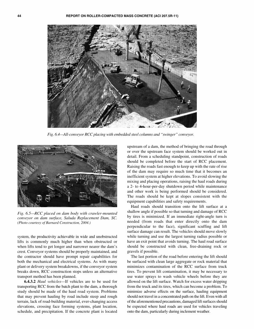
44 REPORT ON ROLLER-COMPACTED MASS CONCRETE (ACI 207.5R-11)
system, the productivity achievable in wide and unobstructedlifts is commonly much higher than when obstructed orwhen lifts tend to get longer and narrower nearer the dam’screst. Conveyor systems should be properly maintained, andthe contractor should have prompt repair capabilities forboth the mechanical and electrical systems. As with manyplant or delivery system breakdowns, if the conveyor systembreaks down, RCC construction stops unless an alternativetransport method has been planned.
6.4.3.2 Haul vehicles—If vehicles are to be used fortransporting RCC from the batch plant to the dam, a thoroughstudy should be made of the haul road system. Problemsthat may prevent hauling by road include steep and roughterrain, lack of road-building material, ever-changing accesselevations, crossing face forming systems, plant location,schedule, and precipitation. If the concrete plant is located
upstream of a dam, the method of bringing the road throughor over the upstream face system should be worked out indetail. From a scheduling standpoint, construction of roadsshould be completed before the start of RCC placement.Raising the roads fast enough to keep up with the rate of riseof the dam may require so much time that it becomes aninefficient system at higher elevations. To avoid slowing themixing and placing operations, raising the haul roads duringa 2- to 4-hour-per-day shutdown period while maintenanceand other work is being performed should be considered.The roads should be kept at slopes consistent with theequipment capabilities and safety requirements.
Haul roads should transition onto the lift surface at ashallow angle if possible so that turning and damage of RCCby tires is minimized. If an immediate right-angle turn isneeded (from roads that enter directly onto the damperpendicular to the face), significant scuffing and liftsurface damage can result. The vehicles should move slowlywhile turning and use the largest turning radius possible orhave an exit point that avoids turning. The haul road surfaceshould be constructed with clean, free-draining rock orgravels if possible.
The last portion of the road before entering the lift shouldbe surfaced with clean large aggregate or rock material thatminimizes contamination of the RCC surface from trucktires. To prevent lift contamination, it may be necessary touse water sprays to wash vehicle wheels before they areallowed on the lift surface. Watch for excess water drippingfrom the truck and its tires, which can become a problem. Tominimize adverse effects on the surface, hauling equipmentshould not travel in a concentrated path on the lift. Even with allof the aforementioned precautions, damaged lift surfaces shouldbe expected where haul roads are used for vehicles travelingonto the dam, particularly during inclement weather.
Fig. 6.4—All-conveyor RCC placing with embedded steel columns and “swinger” conveyor.
Fig. 6.5—RCC placed on dam body with crawler-mountedconveyor on dam surface, Saluda Replacement Dam, SC.(Photo courtesy of Barnard Construction, 2004.)
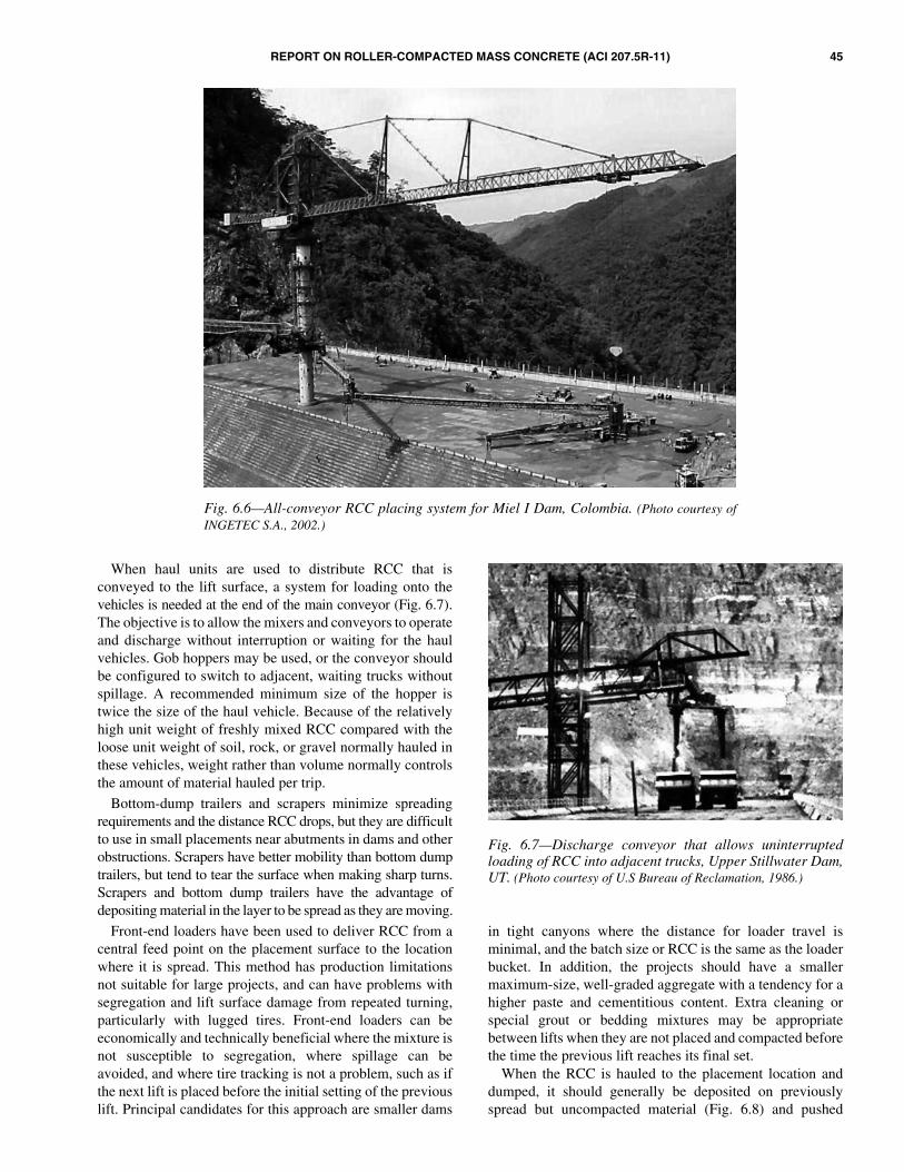
REPORT ON ROLLER-COMPACTED MASS CONCRETE (ACI 207.5R-11) 45
When haul units are used to distribute RCC that isconveyed to the lift surface, a system for loading onto thevehicles is needed at the end of the main conveyor (Fig. 6.7).The objective is to allow the mixers and conveyors to operateand discharge without interruption or waiting for the haulvehicles. Gob hoppers may be used, or the conveyor shouldbe configured to switch to adjacent, waiting trucks withoutspillage. A recommended minimum size of the hopper istwice the size of the haul vehicle. Because of the relativelyhigh unit weight of freshly mixed RCC compared with theloose unit weight of soil, rock, or gravel normally hauled inthese vehicles, weight rather than volume normally controlsthe amount of material hauled per trip.
Bottom-dump trailers and scrapers minimize spreadingrequirements and the distance RCC drops, but they are difficultto use in small placements near abutments in dams and otherobstructions. Scrapers have better mobility than bottom dumptrailers, but tend to tear the surface when making sharp turns.Scrapers and bottom dump trailers have the advantage ofdepositing material in the layer to be spread as they are moving.
Front-end loaders have been used to deliver RCC from acentral feed point on the placement surface to the locationwhere it is spread. This method has production limitationsnot suitable for large projects, and can have problems withsegregation and lift surface damage from repeated turning,particularly with lugged tires. Front-end loaders can beeconomically and technically beneficial where the mixture isnot susceptible to segregation, where spillage can beavoided, and where tire tracking is not a problem, such as ifthe next lift is placed before the initial setting of the previouslift. Principal candidates for this approach are smaller dams
in tight canyons where the distance for loader travel isminimal, and the batch size or RCC is the same as the loaderbucket. In addition, the projects should have a smallermaximum-size, well-graded aggregate with a tendency for ahigher paste and cementitious content. Extra cleaning orspecial grout or bedding mixtures may be appropriatebetween lifts when they are not placed and compacted beforethe time the previous lift reaches its final set.
When the RCC is hauled to the placement location anddumped, it should generally be deposited on previouslyspread but uncompacted material (Fig. 6.8) and pushed
Fig. 6.6—All-conveyor RCC placing system for Miel I Dam, Colombia. (Photo courtesy ofINGETEC S.A., 2002.)
Fig. 6.7—Discharge conveyor that allows uninterruptedloading of RCC into adjacent trucks, Upper Stillwater Dam,UT. (Photo courtesy of U.S Bureau of Reclamation, 1986.)

46 REPORT ON ROLLER-COMPACTED MASS CONCRETE (ACI 207.5R-11)
forward on to the compacted lift surface. This providesremixing action and minimizes clusters of coarse aggregatethat otherwise would tend to occur at the lift interface. WhenRCC is dumped in large piles, larger aggregates tend to rolldown the outside of the piles and create clusters. A generalrule is to limit the height of a pile to 5 ft (1.5 m) or less.Correcting this kind of segregation is nearly impossible if therock has already rolled onto a previously compacted lift.Where this condition occurs, the segregated large aggregateshould be removed and wasted or broadcast onto the RCClayer being spread. As with conventional concrete, RCCshould not be dropped free-fall without chutes or trunksmore than 4 ft (1.3 m).
6.4.4 Placing and spreading—Placing and spreadingmethods have undergone a transformation during the pastdecade of RCC construction. Early dams placed the RCC inhorizontal or nearly horizontal lifts. The RCC was placed ineither a 1 ft (300 mm) compacted lift or in multiple layers ofuncompacted RCC stacked to form a compacted lift up to 3 ft(900 mm) thick. Beginning in the mid-1990s, the slopinglayer method of placement was introduced at Jiangya Dam inChina (Forbes et al. 1999). This technique has rapidly grownin popularity, and will be discussed separately in this chapter.
The preferred technique of placing RCC in a dam is toadvance each lift from one abutment to the other. An exceptionis where the distance from abutment to abutment is shorterthan the distance from the upstream to the downstream face,such as at the bottom of dams in narrow canyons. In thiscase, placement can be started by working in the upstream-downstream direction. Unless it is carefully controlled,placement in the upstream-downstream direction may resultin segregation along lateral placement edges that causeporous zones through the structure. This can be particularlycritical for RCC mixtures with a tendency to segregate.Although the sloping layer method does not alter thisconcept, the higher lift thickness changes the typical operationsrelated to placing and spreading methods.
Some projects have required placing RCC in paving lanes,typically going from abutment to abutment. The problemswith placing RCC in paving lanes are more serious withlower cementitious-content, dryer-consistency, and larger-aggregate mixtures. Spreader boxes attached to dump trucks,spreaders attached to dozer equipment, and paving machineslack mobility and occupy space in narrow areas of the dam.They can be difficult to maneuver at the abutments. Pavinglanes can leave segregation along the edge of the lanes withdam mixtures. The edges can also become too old to becompacted into RCC of the adjacent lane by the time theadjacent lane is placed. The edge also tends to dry out whileexposed before placing the adjacent lane. This has resultedin concerns over poor quality and weakened or permeableplanes in the dam at the interface of paving lanes. This practiceshould be discouraged unless the problems described can besatisfactorily addressed. Motor graders have been used onsome RCC projects for spreading RCC. They are difficult tomaneuver in small areas and at abutments. The tires andblade can damage compacted surfaces. There is also atendency to overwork and rework the surface.
Tracked dozer equipment has proven to be best forspreading RCC. Tracked dozers are fast, sufficiently accurate,and contribute to uniformly compacted RCC. By carefulspreading, a dozer can remix RCC and minimize segregationthat occurs from dumping. Careful attention should be givento ensure that remixing is occurring and that the dozer is notsimply burying segregated material. Dozers using U-shapedblades are typically modified by welding extension plates onthe edges of the blades to limit segregation that can occur asRCC rolls off of the edge during spreading. Dozers shouldhave at least hydraulic tilt capability and preferably bothtilt and angle hydraulic capability. The dependability of theequipment and quality of the operator have a significanteffect on controlling segregation and spreading a uniform liftthickness.
A dozer typically spreads the RCC in a 12 ± 2 in. (300 ±50 mm) thick, loose lift in a manner that allows the dozer tooperate on uncompacted material. Dozers with street grouserrubber tracks, or worn tracks, are preferred so as to minimizebreakdown of the aggregate, shearing of the RCC, or both.Laser surveying equipment is used on many projects forcontrolling the grade of grading lift surfaces.
At Elk Creek Dam, RCC mixtures with a set-retardingadmixture and a Vebe time of 15 to 25 seconds were enddumped in piles on previously spread but not-yet-rolledmaterial at least 40 ft (12 m) from the advancing face(Hopman and Chambers 1988). Mortar was spread on eachhardened lift surface to a thickness of approximately 1 in.(25 mm), similar to the Japanese RCD method. Dozersleveled the piles and spread the RCC forward into 6 in.(150 mm) thick layers until a full lift thickness of 24 in.(600 mm) was reached. Two double-drum 11 ton (10 metricton) vibratory rollers and three 25 to 80 ton (23 to 72 metricton) dozers were able to spread and compact the 24 in.(600 mm) lift thicknesses at a rate of more than 900 yd3/h(690 m3/h). The entire surface of each 6 in. (150 mm) layerwas traversed by at least two passes of the dozer tracks. This
Fig. 6.8—Dumping fresh RCC onto previously placed andspread, uncompacted lift, Deimer Dam Modification. (Photocourtesy of MWH Global, 2007.)

REPORT ON ROLLER-COMPACTED MASS CONCRETE (ACI 207.5R-11) 47
dozer action produced an average density of 146 lb/ft3
(2350 kg/m3), or approximately 98% of the optimumcompaction density. Additional compaction of the roller wasadded only to the 24 in. (600 mm) full thickness of the lift. Ifthe mixture had not contained a retarder, more equipment orthinner lifts would have been needed. Typically, two rollersand one 18 ton (16 metric ton) dozer, with a backup dozer,can spread and roll RCC at a rate of approximately 300 to500 yd3/h (230 to 380 m3/h) in 12 in. (300 mm) thick lifts.
Similar results have been achieved with other RCCmixtures having a relatively plastic mixture consistency. Atthe Nickajack Dam auxiliary spillway project, wet-consistency,air-entrained RCC was spread in two 12 in. (300 mm) thicklifts, with the second layer following as a step behind the firstlayer (Cannon 1993). The first layer was substantiallycompacted before placement of the second layer, and thesecond layer was compacted before the first reached initialset. The advancing layer was approximately 100 ft (30 m) infront of the following layer.
At Upper Stillwater Dam, end dump trucks wereequipped with a tailgate-spreader box, shown in Fig. 6.9,that dumped and spread the RCC in approximately 16 in.(400 mm) thick loose lifts. Only a small dozer was neededfor final spreading with placement rates up to 800 yd3/h(600 m3/h) (Dolen et al. 1988).
Dozers should operate on fresh RCC that has not beencompacted. All turning and crabbing should be performed onuncompacted material. Operating the dozer on a compactedsurface will damage the RCC. When it is necessary for thedozer to drive onto compacted RCC, the operator shouldlimit the movement to straight back and forth travel, travelon rubber mats, or both, such as on lengths of old conveyorbelts. Track marks made before the mixture reaches initialset can be recompacted by the vibratory roller withoutsignificant loss of joint quality. Damaged surfaces that arerecompacted after the mixture has set or dried can developcompaction planes with little or no strength, even when theRCC has an acceptable surface appearance. Where compactionplanes result, the layers will not bond together. This materialcan be easily removed by blowing with an air jet, even manyhours later.
Spreading equipment should leave a flat or plane surfaceof the proper thickness before the roller compacts the lift.Depending on the workability of the mixture, ridges or stepsbetween adjacent passes of the dozer blade can result inuneven compactive effort and variable quality in the RCC.As a general rule, having a flat surface ready to roll in theleast amount of time is more important than having an exactgrade with delayed rolling.
Where conventional concrete mixtures are specified forlimited areas, for example, at the upstream or downstreamface, special procedures are required. If conventionalconcrete is used against a formed face with a dry consistencyRCC mass behind it (Fig. 5.5(c) and (d)), the conventionalmixture should be placed first with the RCC immediatelyspread against and on top of the sloping unformed face of theconventional concrete. The conventional mixture should beproportioned to lose slump rapidly, but not set rapidly. This
allows the RCC to be compacted into the conventionalconcrete before either mixture sets. If the conventionalconcrete does not lose slump soon enough, the roller willsink into it with a variety of ensuing construction problems.If rolling is delayed while waiting for the conventionalmixture to stiffen, the RCC can become too old for propercompaction. If the roller operator simply stays back from theconventional concrete far enough to avoid sinking into it orshoving it up, the two mixtures may not adequately compactor bond together. Conventional concrete is usually neededfor appearance and durability of the exposed face. Theminimum amount that can be stacked against the form,approximately 2 to 6 in. (50 to 150 mm) wide, will provide aconventional concrete appearance. Large compactors,however, cannot be operated that close to the forms. The useof smaller compactors may result in lower-density RCC in thisarea, require placement of thinner lifts, or both. If theconventional concrete zone is wider than approximately 6 in.(150 mm), the conventional concrete is usually consolidatedwith immersion-type vibrators while the adjacent RCC is rolled.
If the RCC has a wetter consistency, and especially if it hasa delayed set, it is possible to place the conventional concretemixture after the RCC. The facing concrete still needs tohave a relatively low slump when RCC compaction isperformed, but it can still be possible to immersion-vibratethe interface region of the RCC and conventional concrete.Experience, coring, and internal destructive investigationshave shown that a poor interface between conventionalconcrete and RCC often results in both sequences ofconventional and RCC interface placement. Efforts areongoing to improve the conventional concrete-RCC interfacearea. The use of GERCC involves pouring grout under orover the uncompacted RCC adjacent to the face of the dam,followed by immersion vibration and roller compaction.This placing method is discussed separately in this chapter.
The most common compacted lift thickness has been 12 in.(300 mm). The trend is to use the thickest lifts compatiblewith the RCC mixture and the spreading and compactionequipment to achieve the specified minimum density. In
Fig. 6.9—RCC dumped and spread with controlled tailgatein 16 in. (400 mm) loose layers prior to compaction. (Photocourtesy of U.S Bureau of Reclamation, 1986.)

48 REPORT ON ROLLER-COMPACTED MASS CONCRETE (ACI 207.5R-11)
Japan, thicker lifts from approximately 1.5 to 3 ft (0.5 to 1.0 m)have been compacted in one lift after being spread by dozersin several layers. A 12 in. (300 mm) thickness is convenientto work with in the field.
Another factor influencing lift thickness is the maximumallowed exposure time before covering one lift with thesubsequent lift. Each project should be studied to optimizethe benefits of various lift thicknesses. Thicker lifts meanlonger exposure times, but fewer lift joints and fewer potentialseepage paths. Thinner lifts result in more potential liftjoints, but allow the joints to be covered sooner, resulting inimproved bond. Mixture proportions will also affect theworkability and, consequently, the ability to achieve uniformdensity for the full lift thickness. The sloped layer methodseeks to optimize the exposure time versus volume of eachlift placed to achieve one thick layer with a large volumecomprised of multiple 12 in. (300 mm) compacted layersbefore the preceding lift has reached its initial set.
At the start of extremely rough foundations and where thefoundation has deep holes that have not been filled withdental or leveling concrete, a front-end loader, excavatorbucket, or conveyor can be used to reach the placement siteto deposit material. Conventional concrete can also be usedto achieve a level working area to start RCC placement.
A small dozer (2 tons [1.8 metric tons]) is needed to startthe foundation and for tight conditions. A small dozer isgenerally capable of spreading RCC at a rate of approximately300 yd3/h (230 m3/h). Undersized dozers decrease productivityif the RCC is dumped in large piles.
6.4.5 Sloped layer placing method—The sloped layermethod (SLM), shown in Fig. 6.10, is a more recent innovationin RCC placing that addresses concerns for maintaining theintegrity of lift joints. This is particularly important for largedams when it is impractical to place subsequent lifts beforethe previously placed lift has reached its initial set. SLM wasfirst conceived during the construction of Jingya Dam inChina (Forbes et al. 1999). The SLM was developed out ofnecessity when the time to place subsequent lifts of RCCbecame too great due to the large volume per lift of RCC.Instead of one large volume of RCC per lift placed over one
shift or more, 10 small-volume lifts of RCC are placedquickly and advance over a longer duration. The SLMinvolves placing multiple lifts of RCC on slopes from 1:10to 1:40 that are subsequently built up to a single layer, up to10 ft (3 m) thick (Forbes 1999). The advancing 12 in. (300 mm)lifts are placed from one abutment to the other betweenformed upstream and downstream faces of the dam. The keyto successful placing with the SLM is to maintain the volumeof each layer small enough to ensure all lifts are placedbefore the initial set of the preceding lift. Changing the slopeof the layers can alter the volume per lift, and thus the timeinterval between each placement. The top lift surface of themassive lift is essentially flat and treated by green-cuttingfollowed by a bonding layer of mortar, similar to typicalRCC practice for mature surfaces. The SLM method issomewhat related to the Japanese horizontally-placed RCDmethod and the traditional stair-step method of placingconventional mass concrete. A series of feather edges at the topand bottom of each sloped layer are treated by trimming, specialplacement procedures to prevent crushing aggregates, or both.
There are several advantages of SLM placing. Placementrates have been shown to increase by 30 to 50% by eliminationof time-consuming lift surface preparations. The 12 in.(300 mm) lifts are placed and compacted rapidly, beforethey have reached initial set, eliminating lift surface cleanupand bonding mortar. The 10 ft (3 m) lift of RCC decreasesthe number construction joints by up to 90% and permits liftsurface cleanup and placement of bonding mortar directly infront, but does not delay the advancing RCC. Critical pathitems, such as lift surface cleanup, curing, and erectingformwork can be carried out independent of the RCCplacing. The number of lifts and slope can be adjusted to fitdifferent form heights. The SLM has also been shown towork well with GERCC for both upstream and downstreamfaces. The exposed surface area of green RCC is decreased,reducing the amount of RCC that might be damaged (andthus removed) in inclement weather. The lower notch overthe RCC placement can be used to pass sudden overtoppingfloods while keeping equipment safely above the surface.
Although SLM can be used to increase productivity, itshould not be used as a corrective action for an undersizedplant. The SLM can be used with a typical 1 to 3% crest fallfor construction drainage purposes, though this requiressomewhat more advanced surveying techniques. Formbracing should be capable of resisting the static and dynamicloads of up to 10 ft (3 m) of freshly compacted RCC. Inaddition, the SLM may limit the options of downstreamforming methods, and finishing of horizontal surfaces ofRCC may be more difficult. The RCC mixture should becohesive and not segregate during the spreading process.
6.5—Compaction6.5.1 Roller selection—Maneuverability, compactive
force per unit of drum width, drum size, vibration, frequency,amplitude, operating speed, availability, and requiredmaintenance are all parameters to be considered in the selec-tion of a roller. The compactive output in volume of concreteper hour obviously increases with physical size and speed of
Fig. 6.10—Sloped layer placing method (SLM) (Forbes 1999).
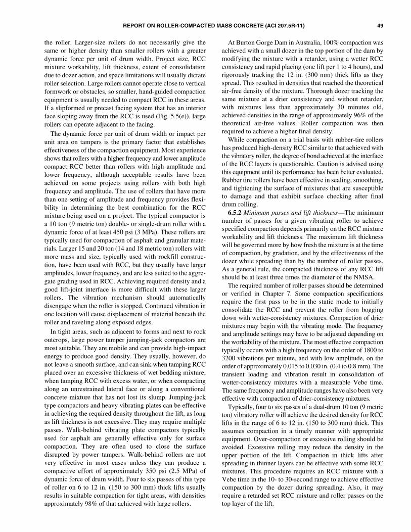
REPORT ON ROLLER-COMPACTED MASS CONCRETE (ACI 207.5R-11) 49
the roller. Larger-size rollers do not necessarily give thesame or higher density than smaller rollers with a greaterdynamic force per unit of drum width. Project size, RCCmixture workability, lift thickness, extent of consolidationdue to dozer action, and space limitations will usually dictateroller selection. Large rollers cannot operate close to verticalformwork or obstacles, so smaller, hand-guided compactionequipment is usually needed to compact RCC in these areas.If a slipformed or precast facing system that has an interiorface sloping away from the RCC is used (Fig. 5.5(e)), largerollers can operate adjacent to the facing.
The dynamic force per unit of drum width or impact perunit area on tampers is the primary factor that establisheseffectiveness of the compaction equipment. Most experienceshows that rollers with a higher frequency and lower amplitudecompact RCC better than rollers with high amplitude andlower frequency, although acceptable results have beenachieved on some projects using rollers with both highfrequency and amplitude. The use of rollers that have morethan one setting of amplitude and frequency provides flexi-bility in determining the best combination for the RCCmixture being used on a project. The typical compactor isa 10 ton (9 metric ton) double- or single-drum roller with adynamic force of at least 450 psi (3 MPa). These rollers aretypically used for compaction of asphalt and granular mate-rials. Larger 15 and 20 ton (14 and 18 metric ton) rollers withmore mass and size, typically used with rockfill construc-tion, have been used with RCC, but they usually have largeramplitudes, lower frequency, and are less suited to the aggre-gate grading used in RCC. Achieving required density and agood lift-joint interface is more difficult with these largerrollers. The vibration mechanism should automaticallydisengage when the roller is stopped. Continued vibration inone location will cause displacement of material beneath theroller and raveling along exposed edges.
In tight areas, such as adjacent to forms and next to rockoutcrops, large power tamper jumping-jack compactors aremost suitable. They are mobile and can provide high-impactenergy to produce good density. They usually, however, donot leave a smooth surface, and can sink when tamping RCCplaced over an excessive thickness of wet bedding mixture,when tamping RCC with excess water, or when compactingalong an unrestrained lateral face or along a conventionalconcrete mixture that has not lost its slump. Jumping-jacktype compactors and heavy vibrating plates can be effectivein achieving the required density throughout the lift, as longas lift thickness is not excessive. They may require multiplepasses. Walk-behind vibrating plate compactors typicallyused for asphalt are generally effective only for surfacecompaction. They are often used to close the surfacedisrupted by power tampers. Walk-behind rollers are notvery effective in most cases unless they can produce acompactive effort of approximately 350 psi (2.5 MPa) ofdynamic force of drum width. Four to six passes of this typeof roller on 6 to 12 in. (150 to 300 mm) thick lifts usuallyresults in suitable compaction for tight areas, with densitiesapproximately 98% of that achieved with large rollers.
At Burton Gorge Dam in Australia, 100% compaction wasachieved with a small dozer in the top portion of the dam bymodifying the mixture with a retarder, using a wetter RCCconsistency and rapid placing (one lift per 1 to 4 hours), andrigorously tracking the 12 in. (300 mm) thick lifts as theyspread. This resulted in densities that reached the theoreticalair-free density of the mixture. Thorough dozer tracking thesame mixture at a drier consistency and without retarder,with mixtures less than approximately 30 minutes old,achieved densities in the range of approximately 96% of thetheoretical air-free values. Roller compaction was thenrequired to achieve a higher final density.
While compaction on a trial basis with rubber-tire rollershas produced high-density RCC similar to that achieved withthe vibratory roller, the degree of bond achieved at the interfaceof the RCC layers is questionable. Caution is advised usingthis equipment until its performance has been better evaluated.Rubber tire rollers have been effective in sealing, smoothing,and tightening the surface of mixtures that are susceptibleto damage and that exhibit surface checking after finaldrum rolling.
6.5.2 Minimum passes and lift thickness—The minimumnumber of passes for a given vibrating roller to achievespecified compaction depends primarily on the RCC mixtureworkability and lift thickness. The maximum lift thicknesswill be governed more by how fresh the mixture is at the timeof compaction, by gradation, and by the effectiveness of thedozer while spreading than by the number of roller passes.As a general rule, the compacted thickness of any RCC liftshould be at least three times the diameter of the NMSA.
The required number of roller passes should be determinedor verified in Chapter 7. Some compaction specificationsrequire the first pass to be in the static mode to initiallyconsolidate the RCC and prevent the roller from boggingdown with wetter-consistency mixtures. Compaction of driermixtures may begin with the vibrating mode. The frequencyand amplitude settings may have to be adjusted depending onthe workability of the mixture. The most effective compactiontypically occurs with a high frequency on the order of 1800 to3200 vibrations per minute, and with low amplitude, on theorder of approximately 0.015 to 0.030 in. (0.4 to 0.8 mm). Thetransient loading and vibration result in consolidation ofwetter-consistency mixtures with a measurable Vebe time.The same frequency and amplitude ranges have also been veryeffective with compaction of drier-consistency mixtures.
Typically, four to six passes of a dual-drum 10 ton (9 metricton) vibratory roller will achieve the desired density for RCClifts in the range of 6 to 12 in. (150 to 300 mm) thick. Thisassumes compaction in a timely manner with appropriateequipment. Over-compaction or excessive rolling should beavoided. Excessive rolling may reduce the density in theupper portion of the lift. Compaction in thick lifts afterspreading in thinner layers can be effective with some RCCmixtures. This procedure requires an RCC mixture with aVebe time in the 10- to 30-second range to achieve effectivecompaction by the dozer during spreading. Also, it mayrequire a retarded set RCC mixture and roller passes on thetop layer of the lift.

50 REPORT ON ROLLER-COMPACTED MASS CONCRETE (ACI 207.5R-11)
6.5.3 Timing and procedures—The appearance of fullycompacted RCC depends on the mixture proportions.Mixtures of the wetter consistency usually exhibit a discerniblepressure wave in front of the roller. Mixtures that have morepaste than necessary to fill aggregate voids and a wetterconsistency will result in visible paste at the surface that maypick up on the roller drum, depending on the constituents andplasticity of the paste. If the paste content is equal to or lessthan the volume needed to fill all the aggregate voids, rock-to-rock aggregate contact occurs, and a pressure wave maynot be apparent. This can also occur if the mixture is simplytoo dry to develop internal pore pressure under the dynamiceffect of the roller.
Compaction should be accomplished as soon as possibleafter the RCC is spread, especially in hot weather. Typically,compaction is specified to be completed within 15 minutesof spreading and 45 minutes from the time of initial mixing.Substantial reductions in strength values can be expected ifthe RCC is compacted when it is more than approximately30 to 45 minutes old, and the mixture temperature is approx-imately 70°F (21°C) or higher. These times can be increasedfor RCC mixtures with extended set times due to pozzolans,admixtures, or cooler temperatures.
The fresh RCC mixture surface should be spread smoothly sothat the roller drum produces a consistent compactive pressureunder the entire width of the drum. If the uncompacted liftsurface of less workable RCC is not smooth, the drum mayover-compact high spots, and under-compact low spots.
Each RCC mixture will have its own characteristicbehavior for compaction depending on temperature,humidity, wind, mixture workability, aggregate fines contentand plasticity, overall gradation, and the NMSA. Generally,RCC mixtures should compact to a uniform texture with arelatively smooth surface. In general, the material should notpick up onto the roller drum, nor should there be free surfacemoisture or pumping of excess water from the mixture.Minor damage from scuff marks and unavoidable dozer tearsin the surface of a freshly compacted lift can usually beimmediately rolled with the vibratory drum in a static modeor with a rubber tire roller. If the mixture was sufficientlyfresh and moist and is rerolled before initial set, an acceptablecondition will result. If the mixture is too old, severelydamaged, or if the lift immediately below has hardened, thererolled RCC may look acceptable, but should be rerolled.Recompacted RCC that is too old or damaged can and shouldbe blown off by an air hose used for general cleanup of loosedebris on the lift.
6.6—Lift joints6.6.1 Lift horizontal joint development—Horizontal joints
are inevitable in mass RCC because of its layered or liftmethod of construction. RCC may be compacted in individuallifts, or several layers may be spread before compactingthem as one lift before initial set of the RCC. For slidingstability, joint shear strength, or water-tightness, designsusually require clean and relatively fresh joint surfaces withgood bond. This is typically done by suitable large vacuumtruck or air-blowing the surface with a wand. Some tests have
shown that sandblasting at 24 and 72 hours after placing canactually reduce bond (Dolen and Tayabji 1988).
When an RCC lift is not covered with additional RCCbefore it reaches initial set, a cold joint is formed. A coldjoint can be generally characterized by either initial settingtime or by joint maturity, which is a result of the averageambient air temperature (AAAT) and time of exposure(TE). Joint maturity is expressed in degree-hours, and iscalculated as
Joint maturity in °F-h = AAAT × (TE)
For example, for 14-1/2 hour exposure at an AAAT of70°F
Joint maturity = (70) × (14-1/2 hours) = 1015°F-h
Degrees Fahrenheit-hour can not be exactly converted todegrees Celsius-hour, or vice versa, without first convertingthe temperature.
Joint maturity in °C-h = [(AAAT × 1.8) + 32] × TE
The setting time of RCC is somewhat more complex todetermine. Many RCC mixtures have high percentages of flyash, retarding admixtures, and cool placement temperatures,all of which may delay initial setting. The standard testprocedure for initial setting is a penetration test that may notbe as reliable for RCC due to its stiff consistency.
Joints are also sensitive to the quantity and characteristicsof the cementitious material and the effectiveness of set-retarding admixtures. Each situation is different, but at anapproximate AAAT of 70°F (21°C), a cold joint usuallybegins to occur in nonretarded RCC by approximately 4 hours,and has most likely developed by 6 hours. A joint that hasbeen exposed less than 6 hours before being covered by thenext lift will have adequate shear strength, but it may not bewatertight unless it is clean and covered with a high-slumpbedding mixture or high cementitious-content RCC mixtureat a maturity of 500 to 1500°F-h (260 to 815°C-h). Afterapproximately 500°F-h (260°C-h), a bedding mixture maybe necessary to achieve the required shear or tensile strength.The exact maturity limit for each project depends on themixture and design requirements.
Not all RCC mixtures require strict limits for lift surfacematurity. The average lift surface exposure for the high-pozzolan mixture at Upper Stillwater Dam averagedapproximately 1000°F-h (220°C-h) due to the large size ofthe dam and construction schedule. The high-paste mixturewas retarded due to the high percentage of pozzolan, the lowplacing temperature, and the use of a chemical water-reducing admixture. The lift joint strengths exceeded thedesign requirements in both direct tension and shear withoutthe use of any supplemental bonding mixtures (Dolen 2003).
High dams, and those where joint shear strength is criticalto stability and safety, should have design assumptions forjoint shear strength confirmed with shear tests of the RCC tobe used, the conditions to be encountered, and the construction
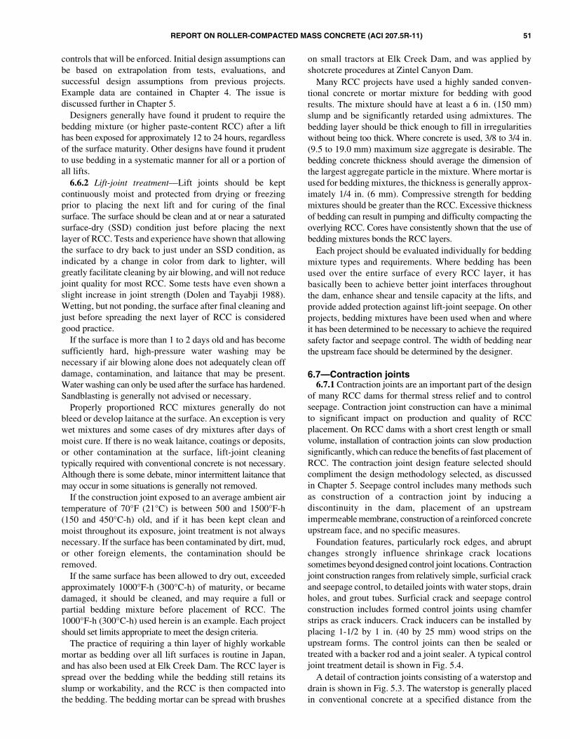
REPORT ON ROLLER-COMPACTED MASS CONCRETE (ACI 207.5R-11) 51
controls that will be enforced. Initial design assumptions canbe based on extrapolation from tests, evaluations, andsuccessful design assumptions from previous projects.Example data are contained in Chapter 4. The issue isdiscussed further in Chapter 5.
Designers generally have found it prudent to require thebedding mixture (or higher paste-content RCC) after a lifthas been exposed for approximately 12 to 24 hours, regardlessof the surface maturity. Other designs have found it prudentto use bedding in a systematic manner for all or a portion ofall lifts.
6.6.2 Lift-joint treatment—Lift joints should be keptcontinuously moist and protected from drying or freezingprior to placing the next lift and for curing of the finalsurface. The surface should be clean and at or near a saturatedsurface-dry (SSD) condition just before placing the nextlayer of RCC. Tests and experience have shown that allowingthe surface to dry back to just under an SSD condition, asindicated by a change in color from dark to lighter, willgreatly facilitate cleaning by air blowing, and will not reducejoint quality for most RCC. Some tests have even shown aslight increase in joint strength (Dolen and Tayabji 1988).Wetting, but not ponding, the surface after final cleaning andjust before spreading the next layer of RCC is consideredgood practice.
If the surface is more than 1 to 2 days old and has becomesufficiently hard, high-pressure water washing may benecessary if air blowing alone does not adequately clean offdamage, contamination, and laitance that may be present.Water washing can only be used after the surface has hardened.Sandblasting is generally not advised or necessary.
Properly proportioned RCC mixtures generally do notbleed or develop laitance at the surface. An exception is verywet mixtures and some cases of dry mixtures after days ofmoist cure. If there is no weak laitance, coatings or deposits,or other contamination at the surface, lift-joint cleaningtypically required with conventional concrete is not necessary.Although there is some debate, minor intermittent laitance thatmay occur in some situations is generally not removed.
If the construction joint exposed to an average ambient airtemperature of 70°F (21°C) is between 500 and 1500°F-h(150 and 450°C-h) old, and if it has been kept clean andmoist throughout its exposure, joint treatment is not alwaysnecessary. If the surface has been contaminated by dirt, mud,or other foreign elements, the contamination should beremoved.
If the same surface has been allowed to dry out, exceededapproximately 1000°F-h (300°C-h) of maturity, or becamedamaged, it should be cleaned, and may require a full orpartial bedding mixture before placement of RCC. The1000°F-h (300°C-h) used herein is an example. Each projectshould set limits appropriate to meet the design criteria.
The practice of requiring a thin layer of highly workablemortar as bedding over all lift surfaces is routine in Japan,and has also been used at Elk Creek Dam. The RCC layer isspread over the bedding while the bedding still retains itsslump or workability, and the RCC is then compacted intothe bedding. The bedding mortar can be spread with brushes
on small tractors at Elk Creek Dam, and was applied byshotcrete procedures at Zintel Canyon Dam.
Many RCC projects have used a highly sanded conven-tional concrete or mortar mixture for bedding with goodresults. The mixture should have at least a 6 in. (150 mm)slump and be significantly retarded using admixtures. Thebedding layer should be thick enough to fill in irregularitieswithout being too thick. Where concrete is used, 3/8 to 3/4 in.(9.5 to 19.0 mm) maximum size aggregate is desirable. Thebedding concrete thickness should average the dimension ofthe largest aggregate particle in the mixture. Where mortar isused for bedding mixtures, the thickness is generally approx-imately 1/4 in. (6 mm). Compressive strength for beddingmixtures should be greater than the RCC. Excessive thicknessof bedding can result in pumping and difficulty compacting theoverlying RCC. Cores have consistently shown that the use ofbedding mixtures bonds the RCC layers.
Each project should be evaluated individually for beddingmixture types and requirements. Where bedding has beenused over the entire surface of every RCC layer, it hasbasically been to achieve better joint interfaces throughoutthe dam, enhance shear and tensile capacity at the lifts, andprovide added protection against lift-joint seepage. On otherprojects, bedding mixtures have been used when and whereit has been determined to be necessary to achieve the requiredsafety factor and seepage control. The width of bedding nearthe upstream face should be determined by the designer.
6.7—Contraction joints6.7.1 Contraction joints are an important part of the design
of many RCC dams for thermal stress relief and to controlseepage. Contraction joint construction can have a minimalto significant impact on production and quality of RCCplacement. On RCC dams with a short crest length or smallvolume, installation of contraction joints can slow productionsignificantly, which can reduce the benefits of fast placement ofRCC. The contraction joint design feature selected shouldcompliment the design methodology selected, as discussedin Chapter 5. Seepage control includes many methods suchas construction of a contraction joint by inducing adiscontinuity in the dam, placement of an upstreamimpermeable membrane, construction of a reinforced concreteupstream face, and no specific measures.
Foundation features, particularly rock edges, and abruptchanges strongly influence shrinkage crack locationssometimes beyond designed control joint locations. Contractionjoint construction ranges from relatively simple, surficial crackand seepage control, to detailed joints with water stops, drainholes, and grout tubes. Surficial crack and seepage controlconstruction includes formed control joints using chamferstrips as crack inducers. Crack inducers can be installed byplacing 1-1/2 by 1 in. (40 by 25 mm) wood strips on theupstream forms. The control joints can then be sealed ortreated with a backer rod and a joint sealer. A typical controljoint treatment detail is shown in Fig. 5.4.
A detail of contraction joints consisting of a waterstop anddrain is shown in Fig. 5.3. The waterstop is generally placedin conventional concrete at a specified distance from the

52 REPORT ON ROLLER-COMPACTED MASS CONCRETE (ACI 207.5R-11)
upstream face of the dam, and joint filler placed upstreamand downstream of the waterstop. A frame with a roll ofwaterstop is frequently mounted to the upstream face formsto keep the material out of the construction area. For contractionjoints with drain holes, the drain holes are formed as theRCC is placed, and an outlet pipe is connected to thedrainage gallery.
The contraction joint through the RCC mass had beenformed by either setting a crack-inducing plate braced on thesurface during spreading, or inserting a plate throughout theloosely spread, uncompacted or compacted RCC. Thesequence for installation of the crack-inducing plate is asfollows: 1) spreading RCC to the contraction joint alignment;2) setting a vertical form plate for the joint with someexternal bracing to maintain the plate vertical; and 3) spreadingRCC on the opposite side of the vertical plate with manuallabor around the plate. Plastic is usually placed around thevertical plate and the metal plate is removed, leaving theplastic in place as a bond breaker.
An alternative method to induce a contraction jointthrough the RCC mass has included using a vertical plate ona vibrator attached to a backhoe, or using a manually operatedjackhammer. The galvanized steel plate is vibrated into placeand left in the RCC as a bond breaker. Plates inserted beforeRCC compaction may be quicker to install, but tend towander from a specified line. If a more definitive contractionjoint is desired, it is recommended to install the crackinducers after compaction (Fig. 6.11).
6.7.2 Grouting contraction joints—To date, few RCCdams have required grouting of contraction joints. With theadvent of much larger dams, arch RCC dams, and rehabilitationof existing dams, contraction joint grouting may becomenecessary. Both transverse and sloping longitudinal contractionjoints were planned and constructed at Meil Dam (Marulanda etal. 2003). The transverse contraction joint spacing wasreduced from the original 200 ft (60 m) spacing to 60 ft (18.5 m)to minimize thermal strains and decrease costs for coolingthe RCC. These contraction joints include PVC seals at theupstream face of the dam. The sloping, longitudinalcontraction joint was constructed in the lower third of thedam and included embedded pipes for post-constructiongrouting, when necessary.
Both longitudinal and transverse contraction joints wereinstalled at Pueblo Dam spillway stability buttress to preventfoundation movement. The contraction joints were formedwith steel plates inserted in every other lift of RCC aftercompaction. Joint displacement meters were installed duringconstruction across the contraction joints so that themaximum opening could be monitored pre- and post-grouting. Contraction joints were isolated by drilling verticalholes through the joint and plugging them with a polyurethanegrout. A manifold and header system placed in the RCCallowed grouting from the bottom of the joint to displace waterupward with mixtures ranging from 2:1 initially to 1:1 or 0.8:1for the grout in the joint (Aberle 2000).
6.8—Forms and facings6.8.1 General—Numerous methods of constructing the
upstream and downstream faces of RCC dams have beenadopted since the first RCC dam was completed in 1982(Arnold and Hansen 2002). Large surface areas that are nothorizontal, such as the upstream and downstream faces ofdams, can be shaped to almost any desired slope orconfiguration, but special consideration should be given toanchorages, appearance, and technique. A review of facingmethods of RCC dams constructed through 2003 revealstypical methods and some recent trends (MDA & Associates2003). The most common facing method for both upstreamand downstream facing is conventional concrete, accountingfor approximately 50% of all dams constructed. Approxi-mately 20% of the RCC dams are using RCC placed directlyagainst forms with an increasing trend toward the GERCCmethod. Various methods of precast forms with and withoutmembranes account for nearly 20% of the upstream andapproximately 10% of the downstream facing methods. Theremaining facing methods include slipforming and reinforcedconcrete. The trends are generally similar for downstreamfacing, with approximately 13% of the dams using eithercompacted or uncompacted RCC. A few of the morecommon methods used to date are discussed briefly asfollows, after general comments. These and other methodsdepicted in Fig. 5.5 and 5.6 for facing RCC dams arediscussed in Chapter 5 and in Schrader (1993).
The height of overhanging sloping forms, such as forspillway surfacing or downstream face forms, restricts areasaccessible to the vibratory rollers. These forms should,therefore, be limited in height or hinged at midheight toreduce the volume of concrete placed under the overhang byconventional methods. Conventional jump-form anchorsmay not have adequate embedment depth for form supportwhen anchored in low-strength RCC, and special anchors aretypically required.
Handling and raising conventional formwork may becomethe limiting factor in the rate of RCC placement. Near the topof a dam, where the volume of RCC per lift is low and theform area for upstream and downstream faces is relatively
Fig. 6.11—Crack inducers inserted by vibrating plate onfront end loader, Miel I Dam, Colombia. (Photo courtesy ofINGETEC S.A., 2002.)

REPORT ON ROLLER-COMPACTED MASS CONCRETE (ACI 207.5R-11) 53
large, more time may be required to set and move the formsthan it takes to place the RCC.
6.8.2 Formed faces—Conventional forming can be used atthe upstream or downstream face with the RCC or conventionalconcrete placed against the forms. Formed facing for bothupstream and downstream facing accounts for approximately70% of all RCC dams constructed through 2003 (includingGRCC facing), with approximately half the damsconstructed with some conventional concrete placed againstthe forms followed by RCC (Fig. 6.12). When RCC is placeddirectly against forms, the resulting RCC surface may haverelatively poor quality (unattractive and porous) unlessparticular attention is given to the placement and type ofmixture used next to the formwork. A conventional concretewith a set retarder has been used to provide a conventionalconcrete appearance and to provide freezing-and-thawingprotection for the structure. Also, a set-retarded conventionalconcrete facing has been used to effectively reduce thenumber of horizontal joints in the facing by vibratingsubsequent lifts of upstream facing together. The sequenceof placement (RCC spread first, followed by facing concreteversus stacking facing concrete, and then spreading RCC)has been performed on numerous projects. Both methodshave benefits and potential problems associated with theprocedures. Placement of RCC first has the benefit of morerapid construction, which can improve other aspects of RCCconstruction. The lateral edge of the RCC and the quality ofthe RCC-concrete interface are of concern, however.Stacking concrete against the form followed by RCC may besomewhat slower, and special workability properties of thefacing concrete are needed. Compaction of RCC on thefacing concrete can cause deformation of wetter-consistencyRCC and the facing concrete. Experimentation is ongoing toimprove the RCC-conventional concrete interface.
6.8.3 Grout-enriched roller-compacted concrete—GERCCis a relatively new method for constructing a dam facing, andaccounts for a growing percentage of RCC dams. GERCCinvolves placing RCC loosely against the forms, followed bythe addition of a fluid grout to fill voids and improve work-ability just before compaction/consolidation. The fluidizedRCC is typically consolidated by large-diameter immersionvibrators adjacent to the forms and standard vibratorsapproximately 1 to 2 ft (0.3 to 0.6 m) away from the forms.Smaller compaction equipment may also be used closer tothe forms. The GERCC method was first tried in 1987 at thecofferdam of the Yantan Dam in China in 1987, and furtherdeveloped at Rongdi Dam (upstream facing) and PuddingDam (upstream and downstream facing) in 1989 and 1992,respectively (Forbes 1999). Since then, nearly all RCC damsin China have used this method. The Olivenhain Dam, with amaximum height 318 ft (97 m) and a maximum length of2586 ft (788 m), used a slightly different method in 2002. TheGERCC method used at Meil Dam is shown in Fig. 6.13though Fig. 6.16.
In the GERCC method, grout is typically poured overfreshly placed RCC and allowed to penetrate the RCC beforeconsolidation. At Olivenhain Dam, the grout was placedbefore the RCC. The grout mixture had a water-cement ratio
(w/c) of approximately 1:1 by volume, and had a marsh coneviscosity of approximately 35 seconds. The amount of groutrequired per unit length of RCC facing varies with both theRCC consistency and the lift height. Typically, approximately2 gal./ft (25 L/m) of grout is required for a mixture with ameasurable consistency of 15 to 20 seconds, and approximately2.5 to 3 gal./ft (30 to 40 L/m) is necessary for a mixture with aconsistency in excess of 40 seconds. Water-reducing and set-retarding admixtures have been used successfully. Attempts touse air-entrained grout in GERCC were generally unsuccessfulin obtaining air-void systems necessary for resistance tofreezing and thawing (McDonald 2002).
GERCC has been consolidated with immersion vibratorsranging from approximately 3 to 6 in. (75 to 150 mm); thesize depends on both the consistency of the RCC and theamount of grout added (Fig. 6.14 and 6.15). This results in azone of GERCC of approximately 1.3 ft (0.4 m) thick normalto the face of the dam. After the addition of the grout, the
Fig. 6.12—Conventional cast-in-place concrete steppedfacing, Toker Dam, Eritrea, Africa. (Photo courtesy of MWHGlobal, 2003.)
Fig. 6.13—GERCC: adding grout onto surface of uncom-pacted RCC along upstream form, Kinta Dam, Malaysia(Forbes 2008).

54 REPORT ON ROLLER-COMPACTED MASS CONCRETE (ACI 207.5R-11)
resulting concrete may have a slump of 1/2 to 3/4 in. (5 to20 mm). Trials should be performed to assure there is sufficientoverlap of the radius of action of the vibrators to assure theGERCC zone is fully consolidated. Compaction shouldimmediately follow consolidating with a 2 to 3 in. (50 to75 mm) overlap of the enriched RCC (Fig. 6.16). The surfaceof GERCC may require cleaning before the next lift of RCC,similar to a conventional concrete facing. Tests by the U.S.Army Corps of Engineers (McDonald 2002) indicate thatadditional study is needed to optimize materials, proportions,and construction procedures that will provide air-voidsystems necessary for GERCC that is resistant to cycles offreezing and thawing.
6.8.4 Precast concrete forms—Vertical and very steepfaces can also be constructed with precast concrete panels or
blocks. Precast concrete panels (Fig. 6.17 and 6.18), consistof relatively thin, high-quality concrete slabs with integral orexternal supports, or both, for erection. These panels canincorporate insulation to protect the interior concrete inextremely cold regions. They can also include a heavy-dutyflexible impervious membrane attached to the rear of thepanel to provide watertightness. Of the 44 dams constructedusing these methods, the height averaged approximately175 ft (53 m), and the crest length averaged approximately1130 ft (345 m) (MDA & Associates 2003).
6.8.5 Uncompacted slope—Uncompacted or compactedRCC is primarily used for the downstream face of dams,accounting for approximately 13% of the dams constructedthrough 2003 (MDA & Associates 2003). If no attempt ismade to compact the edges of an RCC placement, the sides willassume a natural angle of repose of approximately 50 degrees(0.8H:1.0V) with crushed aggregate and 48 degrees(0.9H:1.0V) with rounded aggregate. This assumes reasonablecare with spreading and compacting. Any means of containingloose concrete at the edge (for example, by forming theheight of the lift, by supporting the edge by pins driventemporarily into the RCC, or by mechanical means) can be
Fig. 6.14—GERCC: consolidating GERCC with hand-heldimmersion vibrators at upstream formed facing, Kinta Dam,Malaysia (Forbes 2008).
Fig. 6.15—GERCC: consolidating of GERCC by 6 in.(150 mm) gang-mounted immersion vibrators, JiangyaDam, China (Forbes 2008).
Fig. 6.16—Vibratory roller compaction at GERCC interface,Kinta Dam, Malaysia (Forbes 2008).
Fig. 6.17—Precast panels for upstream face of Willow CreekDam, OR. (Photo courtesy of U.S. Army Corps of Engineers, 1982.)

REPORT ON ROLLER-COMPACTED MASS CONCRETE (ACI 207.5R-11) 55
used to construct steeper faces. On some projects, theexposed face of RCC has also been trimmed after compactionand before development of significant RCC strength.
6.8.6 Curb forming—One means of forming upstream anddownstream faces is using powered curbing machines toslipform conventional concrete curbs or facing elementsagainst which the RCC placement can be initiated withinapproximately 8 hours. This method is more applicable towide valleys and large projects where the rate of rise of theRCC does not exceed the rate of slipforming. At UpperStillwater Dam, it was possible to maintain an averageproduction rate of 2 ft (0.6 m) vertical rise per day, with thecurbs having enough time to develop the necessary strength.Nine slipformed facing dams constructed through 2003 hadan average height of approximately 250 ft (75 m) and crestlength of approximately 2300 ft (700 m).
6.9—Curing and protection from weatherAfter RCC has been placed and compacted, the lift surface
should be cured and protected just as for concrete placed byconventional methods. The surface should be maintained ina moist condition, or at least so that moisture does notescape. It should also be protected from temperatureextremes until it gains sufficient strength. RCC constructionshould typically stop when rain exceeds approximately0.1 in./h (2 to 3 mm/h).
When vehicles are used on the lift surface during rain, thetires may turn the surface into a soft damaged material. Thissituation may require waiting for the RCC to harden so thatextensive cleanup can be undertaken or the entire lift surfaceremoved. When conveyors are used for delivery, and little orno vehicular traffic is required on the RCC, construction cancontinue with slight rainfall. This may require a decrease inthe amount of mixture water used because of the higherhumidity and lack of surface drying.
Immediately after an RCC lift has been compacted, theRCC will not become damaged by light to moderate rain as
long as there is no hauling or traffic on the surface. After arain, hauling on the lift can resume only after the surface hasbegun to dry to a saturated surface-dry condition. A slightlysloped lift surface generally sloped down toward theupstream face of dams will aid in draining free water andspeed resumption of placement operations.
Curing during construction has been accomplished withmodified water trucks on larger projects, and with hand-heldhoses for all-size projects. Trucks should be equipped withfog nozzles that apply a fine mist that does not wash or erodethe surface. They can be augmented with hand-held hoses forareas that are inaccessible to the water truck. Provisionsshould be made for maintaining the damp surface while thetrucks are fueled, maintained, and refilled with water. Careshould be exercised so that the trucks do a minimum amountof turning (and disruption of) the surface. Maintainingaccess on and off every lift during construction can be aproblem that makes trucks impractical. Water tanks andpiping to transport water to the dam for distribution bysprinklers and hand-held hoses rather than water trucks havebeen used successfully on numerous projects.
The final lift of RCC should be cured for an appropriatetime, generally in excess of 14 days. Membrane-curingcompounds are not suitable because of the difficulty inachieving 100% coverage on the relatively rough surface,the probable damage to the membrane from constructionactivity, and the low initial moisture in the mixture. Curingcompounds also do not provide beneficial surface temperaturecontrol that is associated with moist curing.
Unformed sloping surfaces, such as the downstream faceof a dam, are difficult to compact and can be consideredsacrificial and unnecessary to cure, provided this has beenincorporated into the design. Uncompacted exposed RCCwill be subject to raveling due to weathering, which canresult in an unattractive surface. While the outside severalinches will be incapable of achieving any significant strengthor quality, it will serve as sacrificial protection and amoisture barrier for curing of the underlying interior RCC.Where unformed sloping surfaces have been trimmed, moistcuring is necessary.
Protection from temperature extremes and sudden largefluctuations should be provided in environments where it isappropriate, just as for conventionally placed concrete. Thelack of contraction or frequent monolith joints or both inRCC designs adds to the concern about cracking from earlyor rapid temperature drops, or both, because RCC has lowmodulus of elasticity and high creep rates at early ages. Veryfew recent RCC dams have been designed without transversecontraction joints.
The hydration heat generated by the RCC mass and thecontinuous placing sequence can combine to allow placementin cold weather, even when ambient conditions occasionallydrop below freezing, provided that the surface stays at least2°F (1°C) above freezing until it is covered by the subsequentlift. RCC construction in freezing weather may be hamperedby freezing water lines, pumps, valves, and other equipmentproblems at the concrete mixing plant.
Fig. 6.18—Precast concrete forms for vertical upstreamand stair-step downstream faces of Slauda ReplacementDam, SC. (Photo courtesy of Barnard Construction, 2005.)
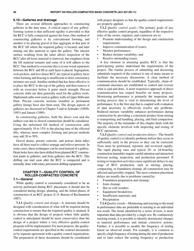
56 REPORT ON ROLLER-COMPACTED MASS CONCRETE (ACI 207.5R-11)
6.10—Galleries and drainageThere are several different approaches to constructing
galleries in the dam mass. A critical aspect of any gallery-forming system is that sufficient rigidity is provided so thatthe RCC is fully compacted against the form. One method ofconstructing galleries is by conventional forming, andanother is by placing gravel or fine aggregate in that part ofthe RCC lift where the required gallery is located, and latermining out this material to open the gallery. The interiorsurface resulting from the latter allows inspection of theRCC after all loose material is removed, but roughness fromthe fill material remains and some of it will adhere to theRCC. One method to overcome this is to use wood separatorsbetween the RCC and fill as each layer is placed. Segregation,rock pockets, and less-dense RCC are typical in gallery faceswhen forming and bracing is insufficient or drier consistencymixtures are used. Another method that has been effective isto place the RCC to the top of the gallery and then remove itwith an excavator before it gains much strength. Precastconcrete slabs are then generally used for the gallery roofs.Slipformed curbs were used as gallery walls at Upper StillwaterDam. Precast concrete sections installed as permanentgallery linings have also been used. The design aspects ofgalleries are discussed in Chapter 5 and in Schrader (1985b,1993) and Jansen (1989).
In constructing galleries, both the direct cost and theindirect cost due to slowed construction should be considered.Using the unformed fill method of construction addsapproximately 10 to 15% to the placing time of the effectedlifts, whereas more complex forming and precast methodsmay add 20 to 50%.
Gravel drains, porous concrete, and porous drain tubeshave all been used to collect seepage and relieve pressure. Insome cases, these techniques can be used instead of a gallery.Drain holes have also been drilled from planned RCC construc-tion joints to galleries, and from galleries into the RCC. Thisdrilling can start soon after the RCC is compacted and isnormally done with rotary percussion drilling equipment.
CHAPTER 7—QUALITY CONTROL OFROLLER-COMPACTED CONCRETE
7.1—GeneralWhile quality control is customarily considered to be an
activity performed during RCC placement, it should also beconsidered during design, planning, and the initial phases ofconstruction of an RCC project (U.S. Bureau of Reclamation1987).
7.1.1 Quality control and design—A structure should bedesigned with consideration of what will be required duringconstruction to ensure that the required quality is attained. Itis obvious that the design of projects where little qualitycontrol is anticipated should be more conservative than thedesign of a project where a very effective quality-controlprogram will be implemented. For most projects, the quality-control requirements are specified in the contract documentsor by separate agreement with a quality control organization.The preparation of these documents should be coordinated
with project designers so that the quality-control requirementsare properly applied.
7.1.2 Quality control goals—The primary goals of anyeffective quality control program, regardless of the respectiveroles of the owner, engineer, and contractor are to:• Promote understanding of the design and construction
requirements;• Improve communication of issues;• Monitor performance;• Reduce mixture variability; and• Resolve outstanding issues.
A key element in attaining quality RCC is that theparticipating parties understand the requirements of theproject. The routine process of submitting and discussingsubmittals required of the contract is one of many means tofacilitate the necessary discussions. A clear method ofcommunication should be established. Typically, chain-of-command structures are established to control and overseewhat is said and done. A more responsive approach of directcommunication has reaped benefits on many projects.Monitoring performance is primarily the inspection andtesting process that is vital to determining the level ofperformance. It is the first step that is coupled with evaluationof data necessary to effectively resolve any problems.Reduced mixture variability enhances performance duringconstruction by providing a consistent product from mixingto transporting and handling, placing, and final compaction.The majority of the remainder of this chapter deals with thespecific elements involved with inspecting and testing ofRCC operations.
7.1.3 Quality control and production delays—The benefitof quality control is to identify problems before they occur orsufficiently early in the process so they can be corrected.Tests must be performed, reported, and reviewed rapidly.The rapid placing rates and typical 20- or 24-hour/dayconstruction timetables require careful attention and interactionbetween testing, inspection, and production personnel. Iftesting or inspection activities cause significant delays to anystage of RCC production, such as mixing, placing,compacting, or foundation cleanup, all construction may beaffected and possibly stopped. The most common placementdelays are usually due to problems caused by:• Foundation preparation and cleanup;• Joint cleanup;• Hot or cold weather;• Equipment breakdown;• Insufficient materials; and• Precipitation
7.1.4 Quality trends—Monitoring and reacting to the trendin performance data are preferable to reacting to an individualtest result. The trend, identified by a series of tests, is moreimportant than data provided by a single test. By continuouslytracking trends, it is possible to identify detrimental changesin material performance and initiate corrective actions.Further, it is possible to modify the frequency of testingbased on observed trends. For example, it is common tospecify a high frequency of testing during the start of productionand to later reduce the testing frequency as production
REPORT ON ROLLER-COMPACTED MASS CONCRETE (ACI 207.5R-11) 57
stabilizes. Once the production develops a manufacturedprocess that is deemed stable, testing and inspection becomemore of a validation process to the design requirements.
7.2—Activities before RCC placement7.2.1 General—RCC placing rates can be significantly
higher than those for conventional concrete. Placing rates inexcess of 1000 yd3/h (760 m3/h) have been achieved on proj-ects. Small structures have been constructed in only a fewdays or weeks. With such rapid placement rates or short-termconstruction periods, problems need to be evaluated andsolutions implemented in a short period of time. Any problemsthat delay RCC placing essentially delay all production.Good communication between the owner, engineer, quality-control personnel, and contractor is essential, and should beestablished in advance of the work.
7.2.2 Preparatory issues—A key element in resolvingpotential problems in advance is to ensure that all participantsunderstand the project requirements and procedures. Basicissues that should be considered in advance are detailed inthe following.
7.2.2.1 Staffing—Sufficient laboratory and inspectionpersonnel should be trained and available for the anticipatedproduction operations. These two groups work together toensure and validate conformance with the design specifications.It is critical that personnel be adequately trained and orientedto recognize acceptable and unacceptable processes andproducts. Credentials may include various testing certificationsand experience. Efforts should include orientations so thatall production and oversight staff are on the same page withregard to acceptability of operations. Many RCC projectsrequire nearly continuous placement operations and staffingmust be sufficient to keep quality-control personnel fresh andnot overworked. Shift overlaps and transitions requireadvance planning. The personnel listed in Table 7.1 are typicalquality-control staffing levels observed on various projects ofvarious sizes. They include testing and inspection personnel.
7.2.2.2 Testing controls—The main objective of thelaboratory and field testing is to produce timely, accuratetesting results. Technicians should be trained in the proper useof the equipment and in the proper testing procedures. Certaincontrols should be developed to check for accuracy and repeat-ability. A procedures manual for large projects should bedeveloped to lay out the policy for testing. Checks, balances,and the flow of critical data should be discussed. Databases thatcan check, store, and report testing can be very useful.
7.2.2.3 Inspection controls—The inspection staff shouldhave project specifications, references, and critical guidelinescompiled and available to review in the field. Inspectors need tobe trained in the entire construction process developed for theproject and the quality issues critical to design performance.
Appropriate inspection reports for the various items to beinspected should be developed.
7.2.2.4 Facilities and equipment—Appropriate testingfacilities and equipment for the size of material and thefrequency of testing should be available in advance of RCC-related work. This process takes time, and is generallyunderestimated. For larger projects, quality-control contractsshould be awarded and given notice to proceed at the sametime as the RCC contract. Facilities need to be constructedand equipment needs to be procured and calibrated. Equipmentshould be selected for the testing specified and additionalnecessary tests. The building should be designed based onthe equipment layout and the testing process anticipated.Enough room should be provided to allow for an orderlyflow of samples to be tested in the laboratory. A canopyattached to the building is usually necessary for largeprojects to allow as large as 1400 lb (635 kg) samples to bedelivered to the laboratory. This allows the RCC to beshaded from direct sunlight, thereby preventing unnecessarydrying out of the sample. Samples can quickly becomeunworkable for the fabrication of cylinders and other testingwhen tested in direct sunlight.
Certain test procedures are critical for construction tobegin and continue uninterrupted. These procedures shouldbe identified and backup equipment, such as density testingequipment, Vebe machines, and cylinder fabricationequipment, should be available. Table 7.2 provides a guideof typical testing facilities used on other projects. High produc-tion rates coupled with long-term strength requirements mayrequire larger cylinder storage/curing rooms or provisions totransfer excess test cylinders to an offsite testing facility.
7.2.2.5 Communications—The design engineer andquality-control staff should meet with the production staff toreview and discuss requirements and procedures for RCCmaterial production, mixing, placement, testing, inspection,and job-site safety. These communication activities shouldbe scheduled frequently, if not daily, to evaluate dailyconstruction activity for the staff and to ensure that safeworking conditions are maintained throughout the job.Adequate radio communication at the job site among keypersonnel of the production, inspection and quality controlorganization, and field engineer staff is critical for avoidingwork stoppages and unnecessary removal of material.
7.2.3 Production issues—Quality-control issues that relateto the production of materials for RCC placement are shownin Table 7.3 as follows:
7.2.3.1 Aggregate production—Sufficient material ofacceptable quality characteristics, grading, and uniformmoisture content should be tested and stockpiled beforestarting RCC. The quality of material processed will have an
Table 7.1—Typical quality control staffing levels
Small projects<10,000 yd3
(< 7650 m3)
Medium projects10,000 to 100,000 yd3
(7650 to 76,500 m3)
Medium to large projects100,000 to 500,000 yd3
(76,500 to 382,500 m3)
Large projects> 500,000 yd3
(> 382,500 m3)
Single shift Single shift Double shift Single shift Double Shift Double shift
Personnel 2 3 6 4 8 20

58 REPORT ON ROLLER-COMPACTED MASS CONCRETE (ACI 207.5R-11)
impact on the quality of the final product of RCC. Aggregatesto be received from a local supplier should be checked forquality and reliability before the aggregates are received.Table 7.3 provides a list of potential tests that may be necessaryto be performed during this production phase. Productionshould be continually monitored and adjustments madewhen quality variations are detected. Stockpile operationsshould be inspected to ensure that improper operations arenot creating segregation and that stockpiles are oriented toprevent cross contamination and reduce fluctuations inaggregate moisture.
7.2.3.2 Aggregate sampling—Sampling needs to bedone as per ASTM D75/D75M. Sampling devices that are
mounted at the end of the conveyor and sample all the waythrough the stream of aggregate are necessary for a represen-tative sample. Two locations are critical for sampling. Tomonitor the efficiency of the crushing operation, samplingon a conveyor should be done just before it goes into thestock pile. This will monitor the performance of the crushingplant. To monitor the possibility of segregation when stock-piling, sampling should be done just before the product goesinto a surge bin before entering the weigh batcher. Thissampling point will indicate if there is segregation during thestockpiling operation.
7.2.3.3 Stockpile temperature—Monitoring the stockpiletemperature is necessary when unusually warm or cold
Table 7.2—Typical laboratory facility for various project sizesSmall projects
<10,000 yd3
(< 7650 m3)
Medium projects10,000 to 100,000 yd3
(7650 to 76,500 m3)
Medium to large projects100,000 to 500,000 yd3
(76,500 to 382,500 m3)
Large projects> 500,000 yd3
(> 382,500 m3)
Laboratory size One converted semi trailer or storage container
Two converted semi trailers or storage containers*
Permanent structure approximately 2500 ft2 (230 m2) or four converted semi trailers or storage containers
Permanent structure3750 ft2 (350 m2)
*One trailer for laboratory testing, and one for equipment storage and cylinder curing.
Table 7.3—Sample quality-control tests and frequencies.
Material tested Test procedure Test standards* Frequency†
Cement Physical/chemical properties ASTM C150/C150M or equivalent Manufacturer’s certification or prequalified
Pozzolan Physical/chemical properties ASTM C618 or equivalent Manufacturer’s certification or prequalified
Admixtures — ASTM C494/C494MASTM C260/C260M Manufacturer’s certification
Aggregates
Specific gravity—absorption ASTM C127ASTM C128 1/week initially, 1/ month
Grading ASTM C117ASTM C136 1/shift or 1/day
Moisture content ASTM C566ASTM C70 Before each shift, or as required
Flat/long particles ASTM D4791CRD-C 119 1/week initially, 1/month
Plasticity of fines — 1/month or 10,000 yd3 (7500 m3)
Sand equivalent ASTM D2419 1/shift or 1/day initially, 1/week
Abrasion resistance ASTM C535ASTM C131 1/month initially, or as needed
Clay lumps and friable particles ASTM C142/C142M 1/week initially, 1/month
RCC
Consistency and density ASTM C1170/C1170M 2/shift, or as required
In-place density ASTM C1040/C1040M 1/h or every 250 yd3 (200 m3)
In-place moisture (double-probe, nuclear gauge only) ASTM C1040/C1040M 1/h or every 250 yd3 (200 m3)
Oven-dry moisture ASTM C566 1/shift or every 1000 yd3 (750 m3)
Mixture proportions—RCC mixture variability ASTM C172/C172M, C1078, C1079 1/week or every 5000 yd3 (4000 m3)
Temperature ASTM C1064/C1064M 1 every 2 hours or every 500 yd3 (400 m3)
Compressive strength‡ ASTM C1435/C1435M 1/day or every 5000 yd3 (4000 m3)
Split tensile strength‡ ASTM C496/C496M 1/day or every 5000 yd3 (4000 m3)
Elastic modulus‡ ASTM C469/C469M 1/day or every 5000 yd3 (4000 m3)
Compaction§ ASTM D1557 Start of materials and RCC production and if changes in compaction characteristics are observed.
*Other appropriate industry standards may be used.†Frequency shown is example typical of thorough agency testing. On projects with less stringent designs, less frequent testing may be appropriate.‡Some projects used approach of relying on control during construction to achieve required quality, making few cylinders and taking cores afterward for verification of materialproperties in-place.§Some projects use this method for determining the moisture content and compaction characteristics of the mixture.
REPORT ON ROLLER-COMPACTED MASS CONCRETE (ACI 207.5R-11) 59
ambient conditions develop during RCC production, especiallywhen temperature constraints on the RCC are very stringent.Information on stockpile temperature may allow productionadjustments that will allow placement to continue duringperiods of marginal temperature performance.
7.2.3.4 Mixing plant sampling and calibration—Themixing plant layout should provide easy access to aggregatestockpiles and methods of sampling all materials withoutinterruption of RCC production. Sampling locations andequipment for cement, pozzolan, aggregates, and concreteshould be determined to safely obtain representative materials.All equipment should be properly calibrated, and calibrationsdocumented. Batching controls and output should bechecked to confirm the plant’s ability to meter and mix thefresh properties of RCC. The mixing time is critical for RCCand needs to be sufficient to ensure that the material isuniform and of the right consistency.
7.2.3.5 Mixer uniformity testing—Uniformity testingshould be done in advance of the RCC test strips and RCCplacement. Methods are based on ASTM C172/C172M,Annex A1 of ASTM C94/C94M, and CRD-C 55. These haveall been used in modified form to conduct uniformity tests offresh RCC, and to establish acceptable mixing procedures inthe field. Uniformity testing samples the final product ofRCC at the mixing plant at three different increments andmeasures the variability of the mixture to assess the thorough-ness of the metering and mixing process. The followingprocess is generally used:
1. A sample of the metered aggregate only is taken first todetermine the aggregate gradation. The batch plant should beallowed to meter the aggregates only. Sampling the materialmay be done by reversing the belt and creating a stockpile,or just simply stopping the belt and sample from the belt. Theresults of this testing should fall within the establishedgradation band that is developed for the combined aggregate;
2. A second evaluation is to meter all of the fresh propertiesof RCC through the mixing plant. Batch style plants andcontinuous flow plants are different. The batch-style plantsshould be sampled from the first, second, and third portion ofthe batched load. The continuous flow plant should besampled from a continuous length of conveyor belt or at theplacement site where a designated volume of RCC can besampled. Alternate considerations are presented as follows.Each of the three samples should be approximately 600 lb(270 kg). Proper sampling and handling techniques are criticalto not influence the uniformity results. This exercise is verylabor intensive and requires a lot of advanced planning. Thefollowing tests should be performed and repeated for thesecond and third sample.
a) Perform one consistency test as per ASTM C1170,Section 9.1, Method A; determine the unit weight as perSection 9.2;
b) Weigh two individual 30 lb (14 kg) samples of thecomposite mixture of RCC for moisture. Calculate theaverage of the two samples;
c) For air-entrained RCC, perform air content of the fullmixture using a standard pressure meter. The sample isconsolidated by a vibrating table;
d) Weigh 200 lb (90 kg) of material for coarse aggregatewash. Wash material over a No. 4 (4.75 mm) screen,until minus No. 4 has been washed through. Towel dryremaining plus No. 4 material until sample is at anSSD condition and calculate the percentage of coarseaggregate;
e) Fabricate a total of two cylinders as per ASTM C1170or C1435/C1435M. Cylinders should be cured as perASTM C31/C31M. RCC cylinders should be kept intheir plastic molds for a minimum of 2 days in thecuring room, with lids fastened tightly, before strippingis done. Low cement-content mixtures are very unstablein their first couple of days. A special standard of careshould be given to these cylinders. Test for compressivestrength at 7 days, as per ASTM C39/C39M.
Table 7.4 summarizes typical results based on previousproject criteria.
7.2.3.6 RCC placement plan—The details of RCCplacement should be documented and discussed in detail.The plan should include preparatory operations, materialssupply, RCC transportation, spreading, compaction, curing,cleanup, supply, and any other operation that may impact theplanned rate of RCC placement. The plan should include adetailed listing of equipment, pertinent characteristics, andcrew composition. In many cases, this discussion serves toresolve issues that may not have been extensively addressedin the contract documents.
7.2.4 RCC test section and test strips—One of the primarypurposes for a test section is for the contractor to demonstrateequipment and procedures to be used for mixing, handling,and placing RCC and conventional concrete, and toprequalify compaction procedures and equipment. It alsoserves as a training and practice area for both quality-controland RCC production personnel. It is important to recognize that,especially if the section is small or full production equipment isnot available, obtaining the same quality as can be expectedunder full production conditions will be difficult or impractical.A separate test section is preferred over starting immediately onthe permanent work because the first placement is typically at acritical section of the structure, at its base.
Table 7.4—Uniformity testing
TestsMaximum allowable
difference, % ASTM Standard
Vebe consistency 15 ASTM C1170/C1170M, Method A
Vebe density 15 ASTM C1170/C1170M, Method A
Water content of full mixture, % 15 ASTM D2216
Air content, % 100 ASTM C231/C231M*
Coarse aggregate, % 15 ASTM C94/C94M
Fabricate compressive strength cylinders for
7-day break25 ASTM C1176/C1176M or
C1435/C1435M
Density of air-free mortar 2 ASTM C94/C94M
*Pressure air content of RCC can be determined by rigidly attaching air meter bowl toa vibrating table and compacting mixture in two lifts under a 34 lb (15 kg) surcharge.

60 REPORT ON ROLLER-COMPACTED MASS CONCRETE (ACI 207.5R-11)
Typically, the test section is two to four lifts high andincludes at least one lift joint requiring joint surface cleanup.The facing system should also be evaluated in the testsection. Test section construction should be staged so thatnumerous operations are not required at the same time. Forexample, surface treatments should be evaluated on one liftsurface, facing construction on another lift surface, andcompaction alternatives on yet another lift surface. The testsection should be started on a firm foundation, often a lift ofRCC used in calibration of the batching and mixing plant.
The workability and density of the RCC mixture areevaluated by laboratory testing, and any mixture proportionadjustments can be fine-tuned during construction of the testsection. This may include adjusting the water content,cement plus pozzolan content, or fine-coarse aggregate ratio.The test section can also be used to determine field densityrequirements. Coring, sawing, test trenches, and demolitionof the test section with heavy equipment provides a methodof evaluating lift-joint quality, a critical feature of RCCdams. Cores representative of the test section mass may bedifficult to recover at early ages. To increase core recovery,a number of measures have been successful. They includethe use of drilling fluids, split core barrels, proper drillselection, and collar installation. Use of a split inner tubecore barrel has been found to minimize drilling damage,particularly at lift joints.
A major goal in test section construction is to evaluate theRCC mixture performance (that is, mixture segregation,mixture proportions, and compactibility). For a number ofprojects, it was advantageous to evaluate mixture performance,including desired moisture content separately from and inadvance of test section construction. This can be done byconstructing test strips at placements of approximately oneequipment width (approximately 10 ft [3 m]) extending 30 ft(10 m) or more in length (approximately two vibratory rollerlengths) and not more than two lifts in thickness. Fieldmaximum density (density versus roller passes) is measured onthe test placements for all the compaction equipment. Thisoperation allows early and independent evaluation ofmixture handling characteristics and compaction performanceand eases later test section activities by reducing test sectionevaluations to production and placement issues.
7.2.5 Determining field density/compaction requirements—It is common to perform field density tests to establish orverify density requirements for construction and forcomparison with laboratory RCC mixture properties usedfor design. One approach for technical specifications is touse an in-place control section to establish the densityrequired for acceptance. Later, additional density controlsections may be done on a regular interval for the mixtureused in RCC production. The following steps illustrate amaximum density determination:
1. Select the location and dimensions of the controlsection (that is, 100 ft [30 m] long and at least two rollerwidths wide);
2. Begin compacting the freshly placed RCC and test thewet density after every two passes until the density is no
longer increasing, or the increase is less than 0.2 lb/ft3
(3.0 kg/m3); and3. Perform sufficient wet density tests and determine the
average maximum wet density (AMD) based on 10 tests.The performance during construction is based on
achieving 99% of the AMD obtained from the most recentcontrol section. If the wet density fails the specified limit, theRCC should be rerolled within approximately 30 minutes afterthe failing test or, if necessary, the RCC should be removed.
The control section moisture content should be monitored.If the in-place moisture content changes by more thanapproximately 0.3% by mass, another control section isnecessary to maintain the equivalent percent compaction.
7.2.6 Checking compaction equipment—Inspectionpersonnel should check compaction equipment for compliancewith specification requirements before the start of work. Ifthere is reason to believe the equipment is not workingproperly, the equipment manufacturer should be consulted.
7.3—Activities during RCC placement7.3.1 General—Inspection is the first opportunity to
observe an RCC problem and institute measures to correct it.In addition to inspection activities, a comprehensive RCCtesting program should monitor the aggregate properties,RCC mixture proportions, fresh concrete properties, hardenedconcrete properties, and in-place compaction. Examples ofpossible tests and test frequencies are given in Table 7.3. Thefrequency and extent of testing should be establishedaccording to the size of the project, the sensitivity of the designto variations in quality, and the rate of RCC production.
Fresh RCC properties may vary with daily, weekly, orseasonal fluctuations in ambient weather conditions. Thevariations generally affect water requirements, compactioncharacteristics during construction, and the quality of theconcrete. Normally, construction activities continue throughouta variety of warm, cold, wet, or dry ambient conditions. Quality-control personnel should ensure that continuous adjustments inmoisture and, if appropriate, other mixture proportions aremade to adapt to these conditions. Communication betweenshifts about these adjustments is also important.
7.3.2 Inspection—Monitoring quality and verifyingquantities are critical. Careful monitoring of these areas willhelp in eliminating variability and unacceptable material atthe point of placement. This also serves as the verification ofthe process. A structure should be built to validate thedesigner’s intent. Each point of monitoring should haveinspection criteria and a remedy for each deficiency. Thiswill help in unnecessary slowdown or shutdowns of the RCCprocess. The following sections contain areas of projectmonitoring. Projects with less stringent design may not needthe amount of monitoring described herein.
7.3.2.1 Batch plant monitoring—The inspector in chargeof the batch plant needs to verify this process through a seriesof daily inspections. The inspection should include verificationof individual batching weights of the different products, suchas cement, fly ash, and the aggregates and water for batch-styleplants, or verification of the volumetric feed of materialsthrough a continuous flow plant. Inspections should also

REPORT ON ROLLER-COMPACTED MASS CONCRETE (ACI 207.5R-11) 61
include moisture content of each aggregate, which is criticalto recalculating the batched water. Verification of deliveredcementitious materials should also be recorded and verified.The inspector should also evaluate the mixture for consistencyand uniformity. Larger projects have a Vebe table at the plantto monitor consistency and density as necessary. This helpsto produce an RCC product that is more consistent and relievea lot of time trying to fix problems with consistency at theplacement, when material is already on the ground. Theconsistency will differ from the plant to the placement due tothe time taken to deliver the product. A correlation should bedeveloped early on to understand these issues. For instance,if the placement is looking for a 25-second consistencytime, the material will probably have to leave the plant at20 seconds. Consistency times reflect the consistency orworkability properties of the mixture, and are highly dependenton water content. Too much water can cause rutting andpumping and affect lift surface cleanup. Too little water cancause segregation and difficulty in achieving full compaction.These problems affect the strengths, densities, and lift jointcohesion and create other problems. Although consistencytimes do not directly report these characteristics, they are auseful tool in determining the desired RCC. Once the inspectorand plant personnel have a trained eye for the necessary work-ability for compaction, the consistency time is useful for spotchecks and record keeping of the mixture performance.
7.3.2.2 RCC placement—Placement inspectors have awide range of activities. The number of inspections neededis dependent on the anticipated production rates and designfeatures requiring monitoring, such as facing concrete,bedding, and precast panels. The actual placement inspectionactivity of the RCC should include lift thickness verification,compaction time, and the required number of roller passes.The rollers need to compact the fresh RCC before it becomesdry and unworkable. Inspectors should look for consistencyand uniformity in the final in-place product of RCC.Communication between testing personnel on the placementis critical to the process of rapid construction of RCC. Onlarge projects, a second inspector may be necessary toinspect other construction activities such as placement ofbedding materials and concrete facing and forming. A thirdinspector may be used to evaluate lift surface treatment andcleanup that usually takes place on a different shift with adifferent crew for the contractor. Inspection as workprogresses, rather than once a full lift is clean, is effective inhelping production restart and continue efficiently. Theinspection staff will double if two shifts are being used forthe placement.
7.3.3 Material testing—All RCC materials should bechecked to confirm that they meet the project specificationrequirements before use in the work. Table 7.3 summarizestypical tests and typical testing frequencies.
7.3.3.1 Cement and pozzolan—Cement and pozzolan arenormally accepted based on manufacturer’s certification. Testsmay also be performed on grab samples during construction oflarge projects under their quality-assurance program.
7.3.3.2 Admixtures—Admixtures are normally acceptedbased on manufacturer’s certification.
7.3.3.3 Aggregates—The moisture content, grading,particle shape, and the quality of the aggregates significantlyaffects the fresh and hardened properties of RCC. Thegrading of the combined sand and coarse aggregates affectsworkability and the ability to effectively compact or consolidateRCC. In addition to standard gradation analyses, the aggregateshould be tested for its quality and variability compared withthe specified or designed requirements. Fine aggregatetesting may include testing for material passing the No. 200(75 μm) sieve. Specific gravity is useful in monitoring thedensity of the fine and coarse aggregate. Other quality testsof aggregate may include the Los Angeles abrasion resistanceor sodium sulfate soundness, which will monitor the qualityand durability of the aggregate, and specific gravity, whichwill help ensure mining in a dense aggregate. Flat andelongated testing will help ensure that coarse aggregateparticle shape is maintained.
Varying moisture in stockpiles will result in varyingworkability of RCC. An increase or decrease in moisture ofa few tenths of 1% can change the compacting characteristics ofRCC. Samples of aggregate, as batched, should be taken andtested at least once per shift to confirm concrete plantmoisture meter readings and to calculate the actual amountof water being used in the RCC mixture.
7.3.4 RCC testing—A variety of RCC quality-control testswere developed to accommodate the wide range of consis-tencies, mixture proportions, and aggregate grading possiblewith RCC. Some tests are adapted from conventionalconcrete procedures, while others are adapted from soilcement or earthwork technology. There is no single set oftests that applies to all RCC mixtures and placing operations.ASTM standard test methods for RCC require that theconcrete shall have a maximum size aggregate of 2 in. (50 mm).If the RCC has aggregate larger than 2 in. (50 mm), samplesshall be obtained by wet sieving over a 2 in. (50 mm) sievein accordance with ASTM C172/C172M.
7.3.4.1 Consistency tests—The Vebe (Fig. 7.1) orsimilar apparatus is used to measure the consistency of manyRCC mixtures, but does not provide a measure of consistencyfor the drier or lower paste-volume RCC (U.S. Bureau ofReclamation 2005). When it is used for the more workabletypes of RCC mixtures, typical consistency times are 10 to30 seconds (Cannon 1974). The Vebe consistency anddensity tests take approximately 15 minutes to perform afterthe sample is delivered to the laboratory. In some instances,Vebe tables at the plant and placement are useful. Placementconsistency will be higher than those taken at the plant. Acorrelation early on will help. Plant tests are taken to ensurethat the product is leaving the plant at the right consistency.Tests at the placement are the verification of the final in-place product. Testing at both points will help eliminate thepossibility of removal of material at the placement. Thistesting is critical early on until the placement staff developsa trained eye for the RCC.
The standard Vebe apparatus for conventional no-slumpconcrete has been modified for RCC. Fresh RCC is placed inthe 1/3 ft3 (9.4 L) cylindrical steel container under asurcharge. The sample is vibrated until it fully consolidates
62 REPORT ON ROLLER-COMPACTED MASS CONCRETE (ACI 207.5R-11)
under the surcharge. The Vebe consistency is the time ittakes to fully consolidate the sample as indicated by a ring ofmortar around the periphery of the surcharge (Fig. 7.2). Thedensity of fresh RCC is determined from the consolidatedsample. ASTM C1170 includes procedures for testing RCCwith either a 27.5 or 50 lb (12.5 or 22.7 kg) surcharge. TheU.S. Army Corps of Engineers (USACE 2000) recommendsusing the smaller surcharge.
7.3.4.2 Density and air-void tests—The maximumdensity of RCC is measured from fresh samples obtained atthe mixing plant or from the placement and compactedaccording to standardized procedures.
The Vebe density test is used as a method to measure thedegree of compaction or air void content. Air voids for bothair-entrained and non-air-entrained RCC can be determinedby compacting or consolidating the fresh RCC into a standardcontainer rigidly attached to the Vebe table and determiningthe air content by the pressure method.
The in-place wet density of RCC is determined indirectlywith a calibrated nuclear density gauge. Sand cone andballoon methods of determining density are generally notsuitable because of the difficulty and time required to excavatethe test hole with undisturbed sides. Two types of apparatusare commercially available for the nuclear test: a single-probe (Fig. 7.3) and a double-probe nuclear density gauge.Testing may take 5 to 15 minutes, depending on the numberof positions that the gauge is rotated (for the single-probedevice), the ease of driving the probe hole, and the numberof depths at which densities are checked. In the U.S., thegauges must be licensed by the Nuclear Regulatory Commission(NRC) and operators must receive NRC-approved training.
Both the single- and double-probe gauge have limitationsdue to their design and geometry. The single-probe gaugecan usually measure up to 12 in. (300 mm) depth. The single-probe gauge takes the average density of the lift from thebottom of the inserted probe to the top surface. The densityresult, however, is weighted to the more easily compactedtop of the lift than the lower portion of the lift, which is moredifficult to compact, and can contain segregated materialwith some RCC mixtures. A 10% drop in density in thebottom 2 in. (50 mm) of the lift may only be recorded as a1% drop in overall density with the single-probe gauge.
The geometry-related problems of the single-probe gaugeare avoided with the double-probe gauge. The density ismeasured horizontally from the source probe to the detectorprobe at the same depth. Thus, individual strata can bemeasured at different depths. The double-probe gauge canmeasure up to 24 in. (600 mm) depth. Though more desirablethan the single-probe gauge, the double-probe apparatus ismore costly, heavier, and more time-consuming to use. Asignificant difficulty with the double-probe gauge occurs ifthe two pilot holes for the probes are not properly aligned inthe RCC. Due to the granular nature of RCC, driving two
Fig. 7.1—Vebe consistency apparatus (ASTM C1170).
Fig. 7.2—Vebe consistency test time with ring of mortar onconsolidated sample. (Photo courtesy of U.S. Bureau of Recla-mation, 1985.)
Fig. 7.3—Single-probe nuclear gauge. (Photo courtesy ofTroxler Electronic Laboratories, 1981.)
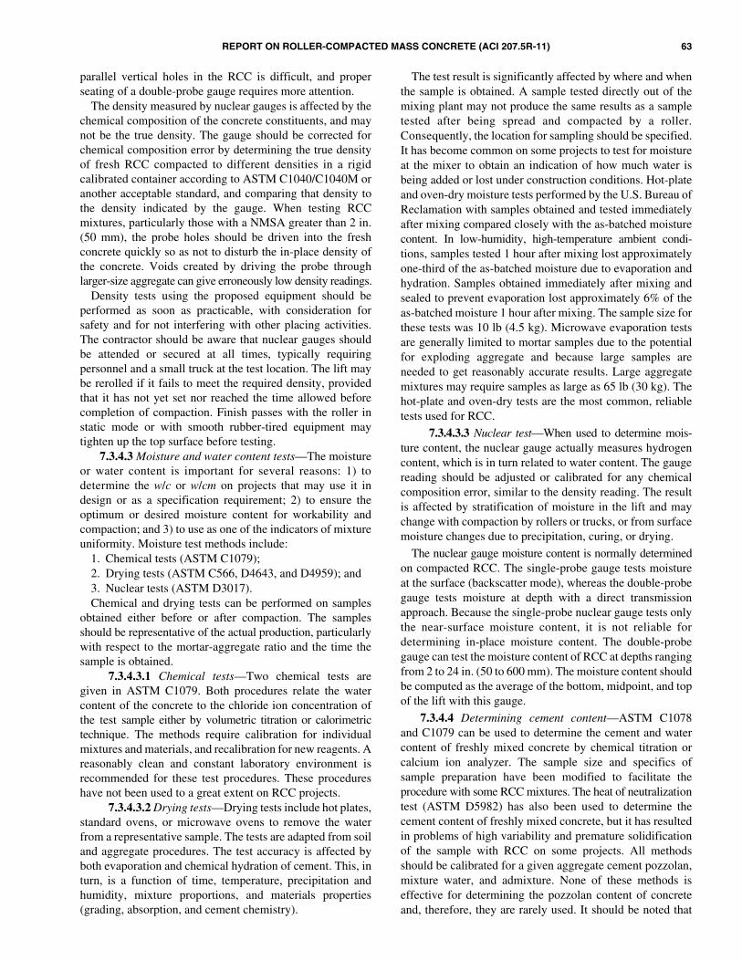
REPORT ON ROLLER-COMPACTED MASS CONCRETE (ACI 207.5R-11) 63
parallel vertical holes in the RCC is difficult, and properseating of a double-probe gauge requires more attention.
The density measured by nuclear gauges is affected by thechemical composition of the concrete constituents, and maynot be the true density. The gauge should be corrected forchemical composition error by determining the true densityof fresh RCC compacted to different densities in a rigidcalibrated container according to ASTM C1040/C1040M oranother acceptable standard, and comparing that density tothe density indicated by the gauge. When testing RCCmixtures, particularly those with a NMSA greater than 2 in.(50 mm), the probe holes should be driven into the freshconcrete quickly so as not to disturb the in-place density ofthe concrete. Voids created by driving the probe throughlarger-size aggregate can give erroneously low density readings.
Density tests using the proposed equipment should beperformed as soon as practicable, with consideration forsafety and for not interfering with other placing activities.The contractor should be aware that nuclear gauges shouldbe attended or secured at all times, typically requiringpersonnel and a small truck at the test location. The lift maybe rerolled if it fails to meet the required density, providedthat it has not yet set nor reached the time allowed beforecompletion of compaction. Finish passes with the roller instatic mode or with smooth rubber-tired equipment maytighten up the top surface before testing.
7.3.4.3 Moisture and water content tests—The moistureor water content is important for several reasons: 1) todetermine the w/c or w/cm on projects that may use it indesign or as a specification requirement; 2) to ensure theoptimum or desired moisture content for workability andcompaction; and 3) to use as one of the indicators of mixtureuniformity. Moisture test methods include:
1. Chemical tests (ASTM C1079);2. Drying tests (ASTM C566, D4643, and D4959); and3. Nuclear tests (ASTM D3017).Chemical and drying tests can be performed on samples
obtained either before or after compaction. The samplesshould be representative of the actual production, particularlywith respect to the mortar-aggregate ratio and the time thesample is obtained.
7.3.4.3.1 Chemical tests—Two chemical tests aregiven in ASTM C1079. Both procedures relate the watercontent of the concrete to the chloride ion concentration ofthe test sample either by volumetric titration or calorimetrictechnique. The methods require calibration for individualmixtures and materials, and recalibration for new reagents. Areasonably clean and constant laboratory environment isrecommended for these test procedures. These procedureshave not been used to a great extent on RCC projects.
7.3.4.3.2 Drying tests—Drying tests include hot plates,standard ovens, or microwave ovens to remove the waterfrom a representative sample. The tests are adapted from soiland aggregate procedures. The test accuracy is affected byboth evaporation and chemical hydration of cement. This, inturn, is a function of time, temperature, precipitation andhumidity, mixture proportions, and materials properties(grading, absorption, and cement chemistry).
The test result is significantly affected by where and whenthe sample is obtained. A sample tested directly out of themixing plant may not produce the same results as a sampletested after being spread and compacted by a roller.Consequently, the location for sampling should be specified.It has become common on some projects to test for moistureat the mixer to obtain an indication of how much water isbeing added or lost under construction conditions. Hot-plateand oven-dry moisture tests performed by the U.S. Bureau ofReclamation with samples obtained and tested immediatelyafter mixing compared closely with the as-batched moisturecontent. In low-humidity, high-temperature ambient condi-tions, samples tested 1 hour after mixing lost approximatelyone-third of the as-batched moisture due to evaporation andhydration. Samples obtained immediately after mixing andsealed to prevent evaporation lost approximately 6% of theas-batched moisture 1 hour after mixing. The sample size forthese tests was 10 lb (4.5 kg). Microwave evaporation testsare generally limited to mortar samples due to the potentialfor exploding aggregate and because large samples areneeded to get reasonably accurate results. Large aggregatemixtures may require samples as large as 65 lb (30 kg). Thehot-plate and oven-dry tests are the most common, reliabletests used for RCC.
7.3.4.3.3 Nuclear test—When used to determine mois-ture content, the nuclear gauge actually measures hydrogencontent, which is in turn related to water content. The gaugereading should be adjusted or calibrated for any chemicalcomposition error, similar to the density reading. The resultis affected by stratification of moisture in the lift and maychange with compaction by rollers or trucks, or from surfacemoisture changes due to precipitation, curing, or drying.
The nuclear gauge moisture content is normally determinedon compacted RCC. The single-probe gauge tests moistureat the surface (backscatter mode), whereas the double-probegauge tests moisture at depth with a direct transmissionapproach. Because the single-probe nuclear gauge tests onlythe near-surface moisture content, it is not reliable fordetermining in-place moisture content. The double-probegauge can test the moisture content of RCC at depths rangingfrom 2 to 24 in. (50 to 600 mm). The moisture content shouldbe computed as the average of the bottom, midpoint, and topof the lift with this gauge.
7.3.4.4 Determining cement content—ASTM C1078and C1079 can be used to determine the cement and watercontent of freshly mixed concrete by chemical titration orcalcium ion analyzer. The sample size and specifics ofsample preparation have been modified to facilitate theprocedure with some RCC mixtures. The heat of neutralizationtest (ASTM D5982) has also been used to determine thecement content of freshly mixed concrete, but it has resultedin problems of high variability and premature solidificationof the sample with RCC on some projects. All methodsshould be calibrated for a given aggregate cement pozzolan,mixture water, and admixture. None of these methods iseffective for determining the pozzolan content of concreteand, therefore, they are rarely used. It should be noted that
64 REPORT ON ROLLER-COMPACTED MASS CONCRETE (ACI 207.5R-11)
cement content is very difficult to obtain with mixturesincorporating limestone aggregates.
7.3.4.5 Evaluating RCC mixture proportions7.3.4.5.1 General—Evaluating RCC mixture proportions
has two main aspects: 1) establishing that materials enter themixer with the desired proportions; and 2) evaluating theworkability of the RCC and the uniformity (or variability) ofthe mixture proportions after it leaves the mixer or after it hasbeen placed and compacted. An essential element of qualitycontrol is the monitoring of batch weights or proportioningweights during RCC production.
7.3.4.5.2 Batch-type plant records and calibration—The primary concerns with RCC, like any concrete, areensuring batch constituents are properly proportioned withinacceptable tolerances, matching aggregate feed rates andstorage capacities to high production rates, finding the bestbatching sequence for each mixture, and getting all materialsuniformly blended within a reasonable mixing time. Thecombined charging, mixing, discharge, and return timedetermines the maximum production rate. Mixture proportionsare input from manual or computer controls. Actual andtarget batch weights of ingredients should be recordedelectronically or on a printout for each batch.
7.3.4.5.3 Continuous mixing plant records and calibra-tion—Mixture proportions are converted to a continuousfeed rate in tons per hour (kilograms per hour). Materialsused for calibration tests are accumulated over a fixed periodof time rather than being measured individually for a separatebatch. As with batch-type plants, materials may be individuallyfed into the mixer from separate bins, or they may beaccumulated on a common final feed belt. This is determinedby whether the mixer has, for example, one belt for allaggregate bins or multiple belts with one for each bin.Calibration with just one belt operating may not apply whenthe plant is in full operation with all feed belts operating.Weigh belts provide weight controls rather than volumetriccontrol, and computer printouts have been used on someRCC projects and are recommended for quality control ofthis proportioning method. As with batch-type plants, adiversion conveyor belt is recommended to sample RCC atthe plant without stopping production. Proper interlocksshould be provided to prevent continued plant operation ifone belt stops or slows. Also, as with batch-type plants, thecontinuous proportioning plant should be calibrated at theminimum, average, and maximum expected productionrates. During production, it may be necessary to recalibratethe plant following a shutdown or if an unusual change in themixture is noted.
7.3.4.6 Temperature—The temperature of RCC, whenmeasured during placement, depends on the temperature ofconcrete ingredients, time to placement, handling anddelivery methods, and the current ambient conditions. Whena maximum or minimum temperature is specified, it usuallyis applicable just before or after compaction. The temperature isnormally determined by thermometers or thermocouplesembedded in the concrete.
7.3.4.7 Making test specimens—Six-inch diameter x 12 in.long (150 x 300 mm) cylinders and other sizes of RCC test
specimens should be made using procedures suited to theconsistency of the mixture, the maximum aggregate size, andthe number of samples to be made before the mixture beginsto dry out. Test specimens should be compacted in rigidmolds or in removable liners supported during compactionby rigid molds. Higher paste-content mixtures with aconsistency time less than approximately 30 seconds aresuited to consolidation by ASTM C1176/C1176M (Fig. 7.4).This procedure uses a vibrating table similar to the Vebe appa-ratus and a surcharge weight such as 20 lb (9.1 kg). The RCCis consolidated in three layers. Other surcharges andmodifications have also been used.
Mixtures that do not respond at all to the Vebe test can becompacted by procedures using vibrating hammers inaccordance with ASTM C1435/C1435M (Fig. 7.5). Thesehammers have been modified by securing a 5-1/4 in. (133 mm)diameter flat plate on the end and have become increasinglypopular for preparing test specimens. The frequency andamplitude of the vibration approximates that of a vibratoryroller. It can be used for RCC of all consistencies. If mortarappears around the plate at less than maximum 15 secondsper each of four lifts, the apparatus should be removed fromthe lift surface.
The modified proctor method of compaction (ASTMD1557) has also been used. The modified proctor methodshould be adjusted for use with RCC by changing the liftthickness and aggregate size from the standard procedure(Arnold et al. 1992). In addition, the compaction hammertends to fracture aggregates and is slow.
Another cylinder preparation method consists of compactionin three layers with a pneumatic tamper with a 5-3/4 in.(146 mm) diameter smooth faced tamping foot. This method
Fig. 7.4—Device for making RCC test cylinders withmodified Vebe apparatus.

REPORT ON ROLLER-COMPACTED MASS CONCRETE (ACI 207.5R-11) 65
is typically used for lower-cementitious-content RCCmixtures (Schrader 1987b).
Regardless of the procedure used, it should be capable ofcompacting the test specimens to a density comparable withthat achieved with the rollers in the field in a standard manner.
7.3.4.8 Strength testing—RCC strength test specimensmay have extremely low early-age compressive strength,which makes handling, stripping, and capping difficult.Some mixtures have compressive strengths of only 200 psi(1.4 MPa) or less at 3 days of age. A procedure that minimizesthe problem of handling and storing these cylinders is tocompact the specimens in thin or precut metal, or PVC linersthat are supported by rigid molds during compaction. The linerthen stays on the sample until immediately before it is tested.
Because of the rapid rate of RCC production and the factthat most projects use design ages of 90 days to 1 year, RCCstrength tests have limited use as a quality-control tool. By thetime reliable results indicating a low ultimate strength areavailable, the project will have progressed well beyond wherethe questionable material was used or where any action can betaken. The information obtained from these tests is useful formonitoring the control maintained on the project, and isvaluable documentation of the work similar to that performedfor conventional concrete dam construction.
If strength testing is required, it is common to cast a set oftest specimens from each shift or each day of production.Tests are normally performed at 7, 28, and 90 days, and extraspecimens are often performed at 1 year on a weekly ormonthly basis. Accelerated curing (ASTM C684) of cylindersand mortar cubes has been used in an effort to get an earlierindication of ultimate strength potential and variability.Accelerated curing appears to have more potential for successwith higher-cementitious-content mixtures and conventionalconcrete aggregates, although standard procedures forRCC have not been developed.
7.3.4.9 Control charts—Control charts are one of the mosteffective methods of tracking, displaying, and interpretingquality-control test data, and their use should be required bythe project specifications. Many quality-control tests can bedirectly input into computers and displayed as real-time infor-mation. Nuclear density and moisture tests can be saved inmost commercial gauges, and test results can be fed into acomputer after each shift to give a shift moving average.Control charts should identify representative trends. A samplecontrol chart for aggregate grading is given in Fig. 7.6. Samplecontrol charts for RCC fresh properties are given in Fig. 7.7and 7.8. Chapter 2 of ACI SP-2 (ACI Committee 311 1999)contains additional information on this subject.
7.4—Activities after RCC placement7.4.1 General—Quality control after placement should
include periodic inspections to ensure that the RCC is beingcontinuously moist-cured and properly protected from damage.
7.4.2 Curing RCC—Quality-control records should bemaintained that document the time and extent of curing, andaction should be taken to correct deficiencies when observed.
7.4.3 Protecting RCC—Quality-control personnel shouldensure that the contractor has protected the RCC surface
Fig. 7.5—Making RCC test cylinders with vibrating hammer.
Fig. 7.6—Typical control charts for tracking fine aggregategrading results by selected individual sieves.

66 REPORT ON ROLLER-COMPACTED MASS CONCRETE (ACI 207.5R-11)
from freezing, drying, or precipitation. When required, RCCshould be covered quickly with plastic or insulating mats toreduce evaporation or protect the surface from rain, dust,snow, and freezing temperatures. If rain is imminent orstarting, inspectors should make sure that the contractorcompletes compaction of uncompacted RCC and immediatelycovers the RCC surfaces to prevent damage.
7.4.4 Post-construction coring—The most accurateinformation on in-place strength can be obtained from corestaken after completion of the project. This normally is notcompleted for 90 days to a year after completion of construction.The number of core tests is usually limited compared with
the normal number of cast cylinder tests made during theconstruction period. Carefully drilled cores also provide anindication of the lift line bonding. Post-construction coring isrecommended for large projects to document the overallperformance of the dam. This is useful for long-term damsafety evaluation. Concrete cores may be obtained from post-construction instrumentation holes, such as inclinometers.Typically, post-construction cores are obtained for the fulldepth of the dam at one or two locations or from galleries,depending on access.
CHAPTER 8—REFERENCES8.1—Referenced standards and reports
The standards and reports listed below were the latesteditions at the time this document was prepared. Becausethese documents are revised frequently, the reader is advisedto contact the proper sponsoring group if it is desired to referto the latest version.
American Concrete Institute207.1R Guide to Mass Concrete207.2R Report on Thermal and Volume Change Effects
on Cracking of Mass Concrete207.4R Cooling and Insulating Systems for Mass Concrete210R Erosion of Concrete in Hydraulic Structures211.1 Standard Practice for Selecting Proportions for
Normal, Heavyweight, and Mass Concrete211.3R Guide for Selecting Proportions for No-Slump
Concrete214R Guide to Evaluation of Strength Test Results of
Concrete304R Guide for Measuring, Mixing, Transporting, and
Placing Concrete325.10R Report on Roller-Compacted Concrete Pavements
ASTM InternationalC31/C31M Standard Practice for Making and Curing
Concrete Test Specimens in the FieldC33/C33M Standard Specification for Concrete
AggregatesFig. 7.7—Typical control charts for consecutive testing ofVebe, unit weight, and moisture content.
Fig. 7.8—Typical control chart for consecutive wet density test results.

REPORT ON ROLLER-COMPACTED MASS CONCRETE (ACI 207.5R-11) 67
C39/C39M Standard Test Method for CompressiveStrength of Cylindrical Concrete Specimens
C42/C42M Standard Test Method for Obtaining andTesting Drilled Cores and Sawed Beamsof Concrete
C70 Standard Test Method for Surface Mois-ture in Fine Aggregate
C94/C94M Standard Specification for Ready-MixedConcrete
C117 Standard Test Method for Materials Finerthan 75-μm (No. 200) Sieve in MineralAggregates by Washing
C127 Standard Test Method for Density, Rela-tive Density (Specific Gravity), andAbsorption of Coarse Aggregate
C128 Standard Test Method for Density, Rela-tive Density (Specific Gravity), andAbsorption of Fine Aggregate
C131 Standard Test Method for Resistance toDegradation of Small-Size Coarse Aggre-gate by Abrasion and Impact in the LosAngeles Machine
C136 Standard Test Method for Sieve Analysisof Fine and Coarse Aggregates
C142/C142M Standard Test Method for Clay Lumps andFriable Particles in Aggregates
C150/C150M Standard Specification for PortlandCement
C172/C172M Standard Practice for Sampling FreshlyMixed Concrete
C231/C231M Standard Test Method for Air Content ofFreshly Mixed Concrete by the PressureMethod
C260/C260M Standard Specification for Air-EntrainingAdmixtures for Concrete
C469/C469M Standard Test Method for Static Modulusof Elasticity and Poisson’s Ratio ofConcrete in Compression
C494/C494M Standard Specification for ChemicalAdmixtures for Concrete
C496/C496M Standard Test Method for SplittingTensile Strength of Cylindrical ConcreteSpecimens
C535 Standard Test Method for Resistance toDegradation of Large-Size Coarse Aggre-gate by Abrasion and Impact in the LosAngeles Machine
C566 Standard Test Method for Total EvaporableMoisture Content of Aggregate by Drying
C595/C595M Standard Specification for BlendedHydraulic Cements
C618 Standard Specification for Coal Fly Ashand Raw or Calcined Natural Pozzolan forUse in Concrete
C666/C666M Standard Test Method for Resistance ofConcrete to Rapid Freezing and Thawing
C684 Standard Test Method for Making,Accelerated Curing, and Testing ConcreteCompression Test Specimens
C1040/C1040M Standard Test Methods for In-PlaceDensity of Unhardened and HardenedConcrete, Including Roller-CompactedConcrete, By Nuclear Methods
C1064/C1064M Standard Test Method for Temperature ofFreshly Mixed Hydraulic-Cement Concrete
C1077 Standard Practice for Agencies TestingConcrete and Concrete Aggregates forUse in Construction and Criteria forTesting Agency Evaluation
C1078 Test Methods for Determining the CementContent of Freshly Mixed Concrete (with-drawn 1998)
C1079 Test Methods for Determining the WaterContent of Freshly Mixed Concrete (with-drawn 1998)
C1138 Standard Test Method for Abrasion Resis-tance of Concrete (Underwater Method)
C1157/1157M Standard Performance Specification forHydraulic Cement
C1170/C1170M Standard Test Method for DeterminingConsistency and Density of Roller-Compacted Concrete Using a VibratingTable
C1176/C1176M Standard Practice for Making Roller-Compacted Concrete in Cylinder MoldsUsing a Vibrating Table
C1435/C1435M Standard Practice for Molding Roller-Compacted Concrete in Cylinder MoldsUsing a Vibrating Hammer
D75/D75M Standard Practice for Sampling AggregatesD1557 Standard Test Methods for Laboratory
Compaction Characteristics of Soil UsingModified Effort (56,000 ft-lbf/ft3 (2,700kN-m/m3))
D2216 Standard Test Methods for LaboratoryDetermination of Water (Moisture)Content of Soil and Rock by Mass
D2419 Standard Test Method for Sand Equiva-lent Value of Soils and Fine Aggregate
D2940/D2940M Standard Specification for GradedAggregate Material for Bases or Subbasesfor Highways or Airports
D3017 Standard Test Method for Water Contentof Soil and Rock in Place by NuclearMethods (Shallow Depth) (withdrawn 2007)
D4643 Standard Test Method for Determinationof Water (Moisture) Content of Soil by theMicrowave Oven Method
D4791 Standard Test Method for Flat Particles,Elongated Particles, or Flat and ElongatedParticles in Coarse Aggregate
D4959 Standard Test Method for Determinationof Water (Moisture) Content of Soil byDirect Heating

68 REPORT ON ROLLER-COMPACTED MASS CONCRETE (ACI 207.5R-11)
D5982 Standard Test Method for DeterminingCement Content of Fresh Soil-Cement(Heat of Neutralization Method)
E329 Standard Specification for AgenciesEngaged in Construction Inspection,Special Inspection, or Testing MaterialsUsed in Construction
U.S. Army Corps of EngineersCRD-C 55 Test Method for Within-Batch Uniformity
of Freshly Mixed ConcreteCRD-C 119 Test Method for Flat and Elongated Particles
in Coarse Aggregate
These publications may be obtained from the followingorganizations:
American Concrete InstituteP.O. Box 9094Farmington Hills, MI 48333-9094www.concrete.org
ASTM International100 Barr Harbor DriveWest Conshohocken, PA 19428-2959www.astm.org
U.S. Army Engineer Research and Development Center 3909 Halls Ferry RoadVicksburg, MS 39180-6199www.erdc.usace.army.mil
8.2—Cited referencesAberle, P., 2000, “Report for Grouting of Contraction Joints
for Pueblo Dam,” Report to U.S. Department of the Interior,U.S. Bureau of Reclamation, Washington, DC, June 14.
Abrams, D., 1918, “Effect of Time of Mixing on theStrength and Wear of Concrete,” ACI JOURNAL, ProceedingsV. 14, No. 6, June, pp. 22-92.
ACI Committee 311, 2007, ACI Manual of ConcreteInspection, SP-2(07), American Concrete Institute, FarmingtonHills, MI, 199 pp.
American Concrete Institute, 2010, “ACI Concrete Termi-nology,” American Concrete Institute, Farmington Hills, MI,http:// Terminology.concrete.org (accessed Jan. 14, 2008).
Andriolo, R. F., 1998, The Use of Roller CompactedConcrete, Oficina de Textos, Brazil.
Arnold, T. E., and Hansen, K. D., 2002, “SeepagePerformance of RCC Dams: Then and Now,” 22nd AnnualUSSD Lecture Series, San Diego, CA, June.
Arnold, T. E., and Johnson, D. L., 1992, “RCC DamDesign Concepts versus Construction Conditions for Stage-coach Dam,” Roller-Compacted Concrete III, ASCE, NewYork, Feb., pp. 291-307.
Arnold, T. E.; Feldsher, T. D.; and Hansen, K. D., 1992,“RCC Test Specimen Preparation—Developments towardStandard Method,” Roller-Compacted Concrete III, ASCE,New York, pp. 341-357.
ASCE, 1988, “Roller Compacted Concrete II,” Proceedingsof the Conference Sponsored by the Construction, Geotech-nical Engineering, and Materials Engineering Divisions ofthe American Society of Civil Engineers, K. D. Hanson andL. K. Guice, eds., New York.
Azari, A. M.; Peyroudin, R.; and Orteha, F., 2003,“Construction Methods for the First Large RCC Dam in Iran,”Roller Compacted Concrete Dams: Proceedings of the FourthInternational Symposium on Roller Compacted ConcreteDams, Swets & Zeitlinger, The Netherlands, pp. 905-912.
Boggs, H. L., and Richardson, A. T., 1985, “USBR DesignConsiderations for Roller-Compacted Concrete Dams,” Roller-Compacted Concrete, ASCE, New York, pp. 123-140.
Campbell, D. B., and Johnson, P. C., 1984, “RCC DamIncorporates Innovative Hydraulic Features,” Proceedings ofthe Conference on Water for Resource Development, ASCE,Hydraulics Division, Coeur d’Alene, ID, pp. 138-142.
Cannon, R. W., 1972, “Concrete Dam Construction UsingEarth Compaction Methods,” Economical Construction ofConcrete Dams, ASCE, New York, pp. 143-152.
Cannon, R. W., 1974, “Compaction of Mass Concretewith Vibratory Roller,” ACI JOURNAL, Proceedings V. 71,No. 10, Oct., pp. 506-513.
Cannon, R. W., 1993, “An Entrained Roller-CompactedConcrete,” Concrete International, V. 15, No. 5, May, pp. 49-54.
Chugoku Regional Construction Bureau, 1981, Constructionof Shimajigawa Dam with Roller-Compacted DamConcrete, Ministry of Construction, Japan.
Clough, R. W., and Zienkiewicz, O. C., 1975, “FiniteElement Methods in Analysis and Design of Dams—Part C,”Criteria and Assumptions for Numerical Analysis of Dams,Proceedings of International Symposium, Swansea, UK,Sept.
Croquevielle, D.; Uribe, L.; and Mutis, R., 2003, “RalcoDam, Chile—Features of its Design and Construction,”Proceedings of the Fourth International Symposium on Roller-Compacted Concrete Dams, Madrid, Spain, pp 589-598.
Crow, R.; Dolen, T.; Oliverson, J.; and Prusia, C., 1984,“Mix Design Investigation—Roller-Compacted ConcreteConstruction, Upper Stillwater Dam, Utah,” USBR ReportREC-ERC-84-15, June.
Day, D. C., 2006, “Natural Weathering Exposure Station,”Treat Island Programs, Engineer Research and DevelopmentCenter, Geotechnical and Structures Laboratory, (http://www.wes.army.mil/SL/TREAT_ISL/index.html).
Ditchey, E., and Schrader, E. K., 1988, “Monksville DamTemperature Studies,” 16th International Congress onLarge Dams, San Francisco, June, International Commissionon Large Dams (ICOLD), V. III, Q62, pp. 379-396.
Dolen, T. P., 1991, “Freezing and Thawing Durability ofRoller Compacted Concrete,” Durability of Concrete, SP-126,American Concrete Institute, Farmington Hills, MI, 1991,pp. 101-114.
Dolen, T. P., 1999, “Mixture Proportioning Investigations,”Soil Cement/Roller Compacted Concrete, Rio SaladoProject, Department of the Interior, U.S. Bureau of Reclama-tion, Denver, CO, 6 pp.
REPORT ON ROLLER-COMPACTED MASS CONCRETE (ACI 207.5R-11) 69
Dolen, T. P., 2002, “Mixture Proportioning Investigationsand Roller Compacted Concrete Construction, Pueblo DamModification,” Fryingpan Arkansas Project, Report No.MERL-2002-02, U.S. Department of the Interior, U.S.Bureau of Reclamation, Denver, CO, 8 pp.
Dolen, T. P., 2003, “Long-Term Performance of RollerCompacted Concrete at Upper Stillwater Dam, Utah,”Proceedings of the International Symposium on RollerCompacted Concrete Dams, Swets & Zeitlinger, TheNetherlands, pp. 1117-1126.
Dolen, T. P., and Tayabji, S. D., 1988, “Bond Strength ofRoller-Compacted Concrete,” Roller-Compacted ConcreteII, ASCE, New York, Feb., pp. 170-186.
Dolen, T. P.; Richardson, A. T.; and White, W. R., 1988,“Quality Control/Inspection—Upper Stillwater Dam,”Roller-Compacted Concrete II, ASCE, New York, Feb.,pp. 277-293.
Dunstan, M. R. H., 1978, “Rolled Concrete—With ParticularReference to Its Use as Heating Material in Concrete Dams,”The Concrete Society, London, UK, Mar.
Dunstan, M. R. H., 1981a, “Rolled Concrete for Dams—Laboratory Study of Properties of High Fly Ash ContentConcrete,” CIRIA Technical Note 105, London, UK, May,96 pp.
Dunstan, M. R. H., 1981b, “Rolled Concrete for Dams—Construction Trials Using High Fly Ash Content Concrete,”CIRIA Technical Note 106, London, UK, May, 94 pp.
Dunstan, M. R. H., 1985, “A Method of Design for MixProportions of Roller-Compacted Concrete to be Used inDams,” Transactions, V. 2, 15th International Congress onLarge Dams, International Commission on Large Dams(ICOLD), Paris, pp. 713-738.
Dunstan, M. R. H.; Dolen, T. P.; Ibanez-de-Aldecoa, R.;and Erharz, J. L., 2003, “Successful Large RCC Dams—What Are the Common Features?” Internal RCC Symposium,Swets & Zeitlinger, The Netherlands, pp. 127-138.
Electric Power Research Institute (EPRI), 1986, “Roller-Compacted Concrete for Dams,” Report AP-4715, PaloAlto, CA, Sept.
Engineering News Record, 1964, “Concrete Gravity DamBuilt Like Earthfill,” V. 173, Dec. 24, 32 pp.
Engineering News Record, 1986, “RCC Dam SurvivesTexas Flood,” Apr. 27.
Forbes, B. A., 1985, “Roller-Compacted Concrete Design,Construction, and Performance of Copperfield Dam,”Institution of Engineers Australia (Queensland Division),Brisbane, Sept.-Oct.
Forbes, B. A., 1999, “Grout Enriched RCC: A History andFuture,” International Water Power and Dam Construction,Wilmington Business Publishing, Kent, UK, June, pp. 34-38.
Forbes, B. A., 2008, “RCC—New Developments andInnovations,” IBRACON 1st Brazilian International RCCSymposium, Salvador, Brazil.
Forbes, B. A.; Yang, L.; Tang, G.; and Yang, K., 1999,“Some Interesting Techniques Developed for High QualityRCC Construction,” Proceedings of the Internal Symposiumon Roller Compacted Concrete Construction, Apr.
Gaekel, L., and Schrader, E. K., 1992, “RCC Mixes andProperties Using Poor Quality Materials—ConcepcionDam,” Roller-Compacted Concrete III, ASCE, New York.
Gentile, G., 1964, “Study, Preparation, and Placement ofLow Cement Concrete, with Special Regard to its Use inSolid Gravity Dams,” Transactions, International Congresson Large Dams, International Commission on Large Dams(ICOLD), Paris, France.
Giovagnoli, M.; Schrader, E.; and Ercoli, F., 1991,“Design and Construction of Concepcion Dam,” Proceedings,International Symposium on RCC Dams, Nov.
Hall, D. J., and Houghton, D. L., 1974, “Roller-Compacted Concrete Studies at Lost Creek Dam,” U.S.Army Engineer District, Portland, OR, June.
Hansen, K. D., 1992, “RCC for Rehabilitation of Dams inUSA—An Overview,” Roller-Compacted Concrete III,ASCE, New York, Feb., pp. 22-46.
Hansen, K. D., 2001, “The Many Faces of RCC,” CivilEngineering, ASCE, V. 71, No. 4, Apr., pp. 48-53.
Hansen, K. D., and Reinhardt, W. G., 1991, Roller-Compacted Concrete Dams, McGraw Hill, New York.
Harris, D. W.; Mohorovic, C. E.; and Dolen, T. P., 2000,“Dynamic Properties of Mass Concrete Obtained fromDam Cores,” ACI Materials Journal, V. 97, No. 3, May-June, pp. 290-296.
Hirose, T., and Yanagida, T., 1981, “Some ExperiencesGained in Construction of Shimajigawa and Okawa Dams,”Proceedings, CIRIA Conference on Rolled Concrete forDams, Construction Industry Research and InformationAssociation, London, UK, June.
Hollingworth, F.; Druyts, F. H. W. H; and Maartens, W. W.,1988, “Some South African Experiences in Design andConstruction of Rollcrete Dams,” 16th InternationalCongress on Large Dams, V. III, International Commissionon Large Dams (ICOLD), pp. 33-51.
Hopman, D. R., 1992, “Lessons Learned from Elk CreekDam,” Roller-Compacted Concrete III, ASCE, New York,Feb., pp. 162-180.
Hopman, D. R., and Chambers, D. R., 1988, “Constructionof Elk Creek Dam,” Roller-Compacted Concrete II, ASCE,New York, Feb., pp. 251-266.
Humphreys, T. D.; Jardine, F. M.; and Nash, J. K., 1965,“The Economic and Physical Feasibility of Soil-CementDams,” 6th International Conference on Soil Mechanics andFoundation Engineering, V. II, Canada.
Jansen, R. B., 1989, Advanced Dam Engineering forDesign, Construction, and Rehabilitation, Van NostrandReinhold, New York.
Johnson, H. A., and Chao, P. C., 1979, “Rollcrete Usage atTarbela Dam,” Concrete International, V. 1, No. 11, Nov.,pp. 20-33.
Lindvall, Richter, and Associates, 1975, Final Report forInvestigation and Reanalysis of Big Tujunga Dam, V. 2, LosAngeles, CA, Oct.
Londe, P., and Lino, M., 1992, “The Faced SymmetricalHard Fill Dam: A New Concept for RCC,” Water Power andDam Construction, Feb.
70 REPORT ON ROLLER-COMPACTED MASS CONCRETE (ACI 207.5R-11)
Marulanda, A.; Amaya, F.; and Schrader E., 1992,“Design of Meil II—A High RCC Dam,” Proceedings ofASCE Roller Compacted Concrete III, San Diego, CA,pp. 83-98.
Marulanda, A.; Rubiano, N. R.; and Castro, A., 2003,“Construction Issues of Meil I Dam, The World’s TallestRCC Dam,” Internal RCC Symposium, Madrid, Spain,pp. 333-343.
McDonald, J. E., 2002, “Grout Enriched Roller-CompactedConcrete—Phase I Investigation,” U.S. Army EngineerResearch and Development Center (CEERD-GM-R), Vicks-burg, MS. http://www.wes.army.mil/SL/HPMS/HPMS_art-3.pdf (accessed March 2, 2008)
McDonald, J. E., and Curtis, N. F., 1997, “Applications ofRoller-Compacted Concrete in Rehabilitation and Replace-ment of Hydraulic Structures,” Technical Report REMR-CS-53, U.S. Army Engineer Waterways Experiment Station,Vicksburg, MS, 184 pp.
McLean, F. G., and Pierce, J. S., 1988, “Comparison ofJoint Strengths for Conventional and Roller-CompactedConcrete,” Roller-Compacted Concrete II, ASCE, NewYork, Feb., pp. 151-169.
McTavish, R. F., 1988, “Construction of Upper StillwaterDam,” Roller-Compacted Concrete II, ASCE, New York,Feb., pp. 267-276.
MDA & Associates, “RCC Dams Database,” Devon, UK,2003.
Ministry of Construction, 1984, “Development in Japan ofConcrete Dam Construction by RCD Method,” Tokyo, Japan.
Moreno, G., 2003, “Challenges in Ralco Dam Construction,”Proceedings of the Fourth International Symposium on RollerCompacted Concrete Dams, Madrid, Spain, pp. 1005-1011.
Oliverson, J. E., and Richardson, A. T., 1984, “UpperStillwater Dam—Design and Construction Concepts,”Concrete International, V. 6, No. 5, May, pp. 20-28.
Omoregie, F. A.; Gutschow, R. A.; and Russell, M. L.,1994, “Cement-Hardened Materials for Abrasion-Erosion inHydraulic Structures,” Concrete International, V. 16, No. 7,July, pp. 47-50.
Parent, W. F.; Moler, W. A.; and Southard, R. W., 1985,“Construction of Middle Fork Dam,” Roller-CompactedConcrete, ASCE, New York, pp. 71-89.
Pauletto, M.; Dunstan, M. R. H.; and Ortega, F., 2003,“Trial Mix Programme and Full-Scale Trials for OlivenhainRCC Dam, USA,” Proceedings of the Fourth InternationalSymposium on Roller Compacted Concrete Dams, Madrid,Spain, pp. 329-338.
Portland Cement Association, 2002, “RCC for Safe DamsResource Notebook,” SP-387, PCA, Skokie, IL.
Raphael, J. M., 1971, “The Optimum Gravity Dam,”Rapid Construction of Concrete Dams, ASCE, New York,pp. 221-247.
Raphael, J. M., 1984, “Tensile Strength of Concrete,” ACIJOURNAL, Proceedings V. 81, No. 2, Mar.-Apr., pp. 158-165.
Reed, G. E.; Rogers, M. F.; and Ehasz, J. L., 2003, “Buildingthe Olivenhain,” Civil Engineering, Apr., pp. 46-53.
Reeves, G. N., and Yates, L. B., 1985, “Simplified Designand Construction Control for Roller-Compacted Concrete,”Roller-Compacted Concrete, New York, pp. 48-61.
Schrader, E. K., 1982, “The First Concrete Gravity DamDesigned and Built for Roller-Compacted ConstructionMethods,” Concrete International, V. 5, No. 10, Oct., pp. 16-24.
Schrader, E. K., 1985, “Watertightness and SeepageControl in Roller-Compacted Concrete Dams,” Roller-Compacted Concrete, ASCE, New York, May, pp. 11-30.
Schrader, E. K., 1987a, “Design for Strength Variability:Testing and Effects on Cracking in RCC and ConventionalConcretes,” Lewis Tuthill Symposium on Concrete andConcrete Construction, SP-104, G. T. Halvorsen, ed., Amer-ican Concrete Institute, Farmington Hills, MI, pp. 1-25.
Schrader, E. K., 1987b, “Compaction of Roller-Compacted Concrete,” Consolidation of Concrete, SP-96,S. H. Gebler, ed., American Concrete Institute, FarmingtonHills, MI, pp. 77-101.
Schrader, E. K., 1993, “Design and Facing Options forRCC on Various Foundations,” Water Power & DamConstruction, Sutton, Surrey, UK, Feb.
Schrader, E. K., 1994, “Roller-Compacted Concrete forDams, State of the Art,” International Conference onAdvances in Concrete Technology, second edition,CANMET, Ottawa, ON, Canada.
Schrader, E. K., 1999, “Shear Strength and Lift JointQuality of RCC,” Hydropower & Dams, Issue 1, pp. 46-55.
Schrader, E. K., 2002, “A Few Interesting RCC Dams,”Roller Compacted Concrete for Dams and Dam Rehabilitation,Proceedings, Portland Cement Association Symposium, SanDiego, CA, Aug. 26-27.
Schrader, E. K., 2006a, “Building Roller-CompactedConcrete Dams on Unique Foundations,” HRW, HCIPublications, Mar., pp. 28-33.
Schrader, E. K., 2006b, “Building Roller-Compacted-Concrete Dams on Difficult Foundations: Practical Examples,”HRW, HCI Publications, May, pp. 1-10.
Schrader, E. K., and Balli, J. A., 2003, “Rompepicos Damat Corral des Palmas with Final Design During Construction,”Roller Compacted Concrete Dams, International RCC DamSymposium, Madrid, Spain, Nov.
Schrader, E. K., and McKinnon, R., 1984, “Constructionof Willow Creek Dam,” Concrete International, V. 6, No. 5,May, pp. 38-45.
Schrader, E. K., and Namikas, D., 1988, “Performance ofRoller-Compacted Concrete Dams,” 16th InternationalCongress on Large Dams, San Francisco, June, Interna-tional Commission on Large Dams (ICOLD), V. III, Q62,pp. 339-364.
Schrader, E. K., and Rashed, A., 2002, “Benefits of Non-Linear Stress-Strain Properties and Membranes for RCCDam Stresses,” International Conference on RCC DamConstruction in Middle East, pp. 331-344.
Schrader, E. K., and Rizzo, P. C., 2003, “Extensive ShearTesting for Saluda Dam Roller Compacted Concrete,” RollerCompacted Concrete Dams, International RCC DamSymposium, Madrid, Spain, pp. 1045-1056.
REPORT ON ROLLER-COMPACTED MASS CONCRETE (ACI 207.5R-11) 71
Schrader, E. K., and Stefanakos, J., 1995, “RCC Cavitationand Erosion Resistance,” Proceedings of the InternationalSymposium on Roller Compacted Concrete, pp. 1175-1188.
Schrader, E. K., and Thayer, H. J., 1982, “Willow CreekDam—A Roller-Compacted Concrete Fill,” Transactions,V. 4, 14th International Congress on Large Dams, Rio deJaneiro, International Commission on Large Dams(ICOLD), Paris, pp. 453-479.
Sexton, D. L.; Hurt R. L.; and Lewis, R. G., “RCC DamConstruction and Method,” United States Patent and TrademarkOffice, Washington, DC. http://patimg1.uspto.gov/.piw?Docid= 4659252&idkey=NONE (accessed Dec. 9, 2010)
Shelke, V. C.; Dunstan, M. R. H.; Hinks, J. L.; andZelenka, T., 2006, “Construction of Three RCC DamsForming Part of the Ghatghar Pumped Storage Project inIndia,” Improvements in Reservoir Construction, Operationsand Maintenance, 14th Conference of the British DamSociety, University of Durham, pp. 406-411.
Sivley, W. E., 1976, “Zintel Canyon Optimum GravityDam,” Transactions, V. 5, 12th International Congress onLarge Dams, pp. 141-145.
Soroushian, P.; Choi, K.-B.; and Abdulazig, A., 1986,“Dynamic Constitutive Behavior of Concrete,” ACIJOURNAL, Proceedings V. 83, No. 2, Mar.-Apr., pp. 251-259.
Tarbox, G. S., and Hansen, K. D., 1988, “Planning,Design, and Cost Estimates for RCC Dams,” Roller-Compacted Concrete II, ASCE, New York, Feb., pp. 21-38.
Tatro, S. B., 1999, “Commentary on the Corps of EngineersApproach to Thermal Analysis of RCC Structures,”Proceedings of the International Symposium on RollerCompacted Concrete Dam, Chinese Society for HydroelectricEngineering, Chengdu, China.
Tatro, S. B., and Schrader, E. K., 1985, “ThermalConsiderations for Roller-Compacted Concrete,” ACIJOURNAL, Proceedings V. 82, No. 2, Mar.-Apr., pp. 119-128.
Tatro, S. B., and Hinds, J. L., 1992, “Roller-CompactedConcrete Mix Design,” Roller-Compacted Concrete III,ASCE, New York, pp. 323-340.
Tatro, S. B., and Schrader, E. K., 1992, “Thermal Analysisfor RCC—A Practical Approach,” Roller-CompactedConcrete III, ASCE, New York, pp. 389-406.
Tayabji, S. D., and Okamoto, A. S., 1987, “Bonding ofSuccessive Layers of Roller-Compacted Concrete,”Construction Technology Laboratories, Skokie, IL.
Technical Center for National Land Development, 1981,“Technical Guide to RCD Construction Method,” Japan, July.
Tynes, W. O., 1973, “Feasibility Study of No-SlumpConcrete for Mass Concrete Construction,” MiscellaneousPaper No. C-73-10, U.S. Army Corps of Engineers, Water-ways Experiment Station, Vicksburg, MS, Oct., 29 pp.
United States Society on Dams, 2003, “RCC Constructionfor Dam Rehabilitation,” Denver, CO.
USACE, 1984, “Willow Creek Dam Concrete Report,”V. 1 and 2, U.S. Army Corps of Engineers, Walla Walla, WA.
USACE, 1993, “Structural Design Using the Roller-Compacted Concrete (RCC) Construction Process,” ETL 1110-2-343, U.S. Army Corps of Engineers, Washington, DC, 25 pp.
USACE, 1994a, “Nonlinear, Incremental StructuralAnalysis of Massive Concrete Structures,” ETL 1110-2-265,U.S. Army Corps of Engineers, Washington, DC, 75 pp.
USACE, 1994b, “Standard Practice for Concrete for CivilWorks Structures,” EM 1110-2-2000, U.S. Army Corps ofEngineers, Washington, DC, 124 pp.
USACE, 1995a, “Gravity Dam Design,” EM No. 1110-2-2200, U.S. Army Corps of Engineers, Washington, DC, 88 pp.
USACE, 1995b, “Seismic Design Provisions for RollerCompacted Concrete Dams,” EP 1110-2-12, Washington,DC, 117 pp.
USACE, 1995c, “Earthquake Design and Analysis forCorps of Engineers Projects,” ER 1110-2-1806, Wash-ington, DC, 25 pp.
USACE, 1997, “Thermal Studies of Mass Concrete Struc-tures,” ETL 1110-2-542, U.S. Army Corps of Engineers,Washington, DC, 75 pp.
USACE, 2003, “Structural Design and Evaluation of OutletWorks,” EM 1110-2-2400, Washington, DC, 143 pp.
USACE, 2006, “Roller-Compacted Concrete,” EM 1110-2-2006, U.S. Army Corps of Engineers, Washington, DC, 77 pp.
U.S. Bureau of Reclamation, 1976, “Design of GravityDams,” Denver, CO, 553 pp.
U.S. Bureau of Reclamation, 1977a, “Design Criteria forConcrete Arch and Gravity Dams,” Engineering MonographNo. 19, Feb.
U.S. Bureau of Reclamation, 1977b, “Laboratory TestingProgram to Evaluate Physical Properties of Auburn DamDesign Concrete Mix for Rapid Strain Rates—Central ValleyProject, California,” Memorandum from Chief, Dam Branch toChief, Concrete and Structural Branch, Denver, CO, Aug. 29.
U.S. Bureau of Reclamation, 1978, “Design and Analysisof Auburn Dam,” Dynamic Studies, V. 4, Denver, CO, Apr.
U.S. Bureau of Reclamation, 1987, “Guidelines forDesigning and Constructing Roller-Compacted ConcreteDams,” ACER Technical Memorandum No. 8, Denver, CO.
U.S. Bureau of Reclamation, 1992, “Concrete ConstructionData, Camp Dyer Diversion Dam Modification,” Feb.
U.S. Bureau of Reclamation, 2005, “Roller-CompactedConcrete, Design and Construction Considerations forHydraulic Structures,” Technical Service Center, Denver,CO, pp. 14-15.
U.S. Committee on Large Dams, 1994, “Annotated Bibliog-raphy on Roller-Compacted Concrete Dams,” Denver, CO, June.
Wallingford, V. M., 1970, “Proposed New Technique forConstruction of Concrete Gravity Dams,” Transactions,V. 4, 10th International Congress on Large Dams,Montreal, QC, Canada, International Commission on LargeDams (ICOLD), Paris, pp. 439-452.
Warren, E., 2009, “Building an RCC Dam in the JordanValley,” International Water Power and Dam Construction,Global Trade Media, UK, Aug.
Wenquan, L; Huizhen, L.; Zhen, H.; and Yajie, L., 1997,“Use of High-Range Retarder-Plasticizer for Roller-Compacted Concrete of the Three Gorges Project in China,”Superplasticizers and Other Chemical Admixtures inConcrete, SP-173, V. M. Malhotra, ed., American ConcreteInstitute, Farmington Hills, MI, pp. 835-854.

As ACI begins its second century of advancing concrete knowledge, its original chartered purposeremains “to provide a comradeship in finding the best ways to do concrete work of all kinds and inspreading knowledge.” In keeping with this purpose, ACI supports the following activities:
· Technical committees that produce consensus reports, guides, specifications, and codes.
· Spring and fall conventions to facilitate the work of its committees.
· Educational seminars that disseminate reliable information on concrete.
· Certification programs for personnel employed within the concrete industry.
· Student programs such as scholarships, internships, and competitions.
· Sponsoring and co-sponsoring international conferences and symposia.
· Formal coordination with several international concrete related societies.
· Periodicals: the ACI Structural Journal and the ACI Materials Journal, and Concrete International.
Benefits of membership include a subscription to Concrete International and to an ACI Journal. ACImembers receive discounts of up to 40% on all ACI products and services, including documents, seminarsand convention registration fees.
As a member of ACI, you join thousands of practitioners and professionals worldwide who share acommitment to maintain the highest industry standards for concrete technology, construction, andpractices. In addition, ACI chapters provide opportunities for interaction of professionals and practitionersat a local level.
American Concrete Institute38800 Country Club DriveFarmington Hills, MI 48331U.S.A.Phone: 248-848-3700Fax: 248-848-3701
www.concrete.org
American Concrete Institute®
Advancing concrete knowledge
The AMERICAN CONCRETE INSTITUTE
was founded in 1904 as a nonprofit membership organization dedicated to publicservice and representing the user interest in the field of concrete. ACI gathers anddistributes information on the improvement of design, construction andmaintenance of concrete products and structures. The work of ACI is conducted byindividual ACI members and through volunteer committees composed of bothmembers and non-members.
The committees, as well as ACI as a whole, operate under a consensus format,which assures all participants the right to have their views considered. Committeeactivities include the development of building codes and specifications; analysis ofresearch and development results; presentation of construction and repairtechniques; and education.
Individuals interested in the activities of ACI are encouraged to become a member.There are no educational or employment requirements. ACI’s membership iscomposed of engineers, architects, scientists, contractors, educators, andrepresentatives from a variety of companies and organizations.
Members are encouraged to participate in committee activities that relate to theirspecific areas of interest. For more information, contact ACI.
www.concrete.org
Report on Roller-Compacted Mass Concrete
American Concrete Institute®
Advancing concrete knowledge