report on geotechnical investigation proposed residential
TRANSCRIPT
Report on Geotechnical Investigation
Proposed Residential Development 1 Avon Road, Pymble
Prepared for Ausbao Pymble Pty Ltd
Project 84887.01 June 2015

Geotechnical Investigation, Proposed Residential Development Project 84887.01 1 Avon Road, Pymble June 2015
Table of Contents
Page
1. Introduction ................................................................................................................... 1
2. Previous Assessment ................................................................................................... 1
3. Site Description ............................................................................................................ 3
4. Regional Geology ......................................................................................................... 4
5. Field Work Methods ...................................................................................................... 4
6. Field Work Results ........................................................................................................ 5
7. Laboratory Testing ........................................................................................................ 7
8. Proposed Development ................................................................................................ 8
9. Comments .................................................................................................................... 8
9.1 Geotechnical Model ............................................................................................. 8
9.2 Excavation Conditions ......................................................................................... 9
9.3 Excavation Support............................................................................................ 10
9.3.1 General .................................................................................................. 10
9.3.2 Temporary Batters.................................................................................. 11
9.3.3 Design of Lateral Support ....................................................................... 11
9.3.4 Ground Anchors ..................................................................................... 13
9.3.5 The Effect of the Proposed Basements on Rail Infrastructure ................ 14
9.4 Vibrations .......................................................................................................... 15
9.5 Foundations ....................................................................................................... 16
9.6 Floor Slabs ........................................................................................................ 17
9.7 Seismic Design .................................................................................................. 17
9.8 Further Investigation .......................................................................................... 18
10. Limitations .................................................................................................................. 18
Appendix A: About this Report
Appendix B: Drawings
Appendix C: Results of Field Work
Appendix D: Vibration Notes

Page 1 of 19
Geotechnical Investigation, Proposed Residential Development Project 84887.01 1 Avon Road, Pymble June 2015
Report on Geotechnical Investigation
Proposed Residential Development
1 Avon Road, Pymble
1. Introduction
This report presents the results of a geotechnical investigation carried out by Douglas Partners Pty Ltd
(DP) for a proposed residential development at 1 Avon Road, Pymble. The investigation was carried
out in accordance with DP's proposal SYD150491-Rev1 dated 6 May 2015 and was commissioned by
Mr Jason Gao of Ausbao Pymble Pty Ltd (AP), the developer of the property, on 18 May 2015. The
work was carried out in consultation with Price Waterhouse Coopers Pty Ltd (PWC), project managers
and Marchese Partners International Pty Ltd, structural engineers for the project.
It is understood that the proposed development of the site will include the construction of three multi-
storey buildings (up to 9 storeys) with an associated common underground basement up to four levels
deep. Site investigation was carried out to provide information on subsurface conditions for the
design of earthworks, foundations, retaining walls and drainage.
Residential buildings are also understood to be proposed for the north-west section of the site, on the
properties accessed via Beechworth Road. A separate report has been prepared for these residential
developments.
The investigation included the drilling of eight boreholes, the installation of a groundwater monitoring
wells and laboratory testing of selected samples. The details of the field work are presented in this
report, together with comments and recommendations on the issues listed above.
2. Previous Assessments
A geotechnical assessment has previously been carried out for the site by Mr Bruce Walker of JK
Geotechnics Pty Ltd (JK) and presented in a report dated 7 May 2015 (Report No. 23513 Rev 3). This
assessment was prepared as part of the Land and Environment Court of NSW proceedings.
This assessment comprised a site walkover by Mr Walker, inspection of the surrounding area and
review of available information.
The development was specified to include excavations ranging from 12 m to 20 m depth and their
assessment indicated the following:
The anticipated geological profile comprised clays to relatively shallow depths overlying shale
which progressively increases in depth. It noted the presence of Hawkesbury Sandstone in the
area at lower elevations.
The nature of the proposed development is relatively routine and proven engineering solutions are
available for the proposed extent of excavation

Page 2 of 19
Geotechnical Investigation, Proposed Residential Development Project 84887.01 1 Avon Road, Pymble June 2015
No landslides are known on the North Shore ridgeline in the Ashfield Shale although instability can
occur in filled embankments and cut slopes.
No evidence of instability was observed in the adjacent fill embankment within the rail corridor.
A landslide risk assessment to determine the qualitative risk of the site of various site hazards
features was carried out in accordance with the Australian Geomechanics Society ‘Practice Note-
Guidelines for Landslide Risk Management (AGS2007c). An excerpt of the accompanying table on
risk is provided in Table 1. It should be noted that the table in the JK report includes reference to
fill batter on north-west side.
Table 1: “Summary of Risk Assessment to Property”
POTENTIAL
LANDSLIDE
HAZARD
Overall Instability
of Existing Natural
Hillside Slope
Instability of Railway Fill
Embankment
Instability of
Possible Cut
Batters at
1V:@H
Instability of
Proposed Retaining
Walls
Assessed
Likelihood
<10-5pa
Say, RARE to
BARELY CREDIBLE
≈ 10-4 pa
UNLIKELY
≈ 10-4 pa
UNLIKELY
≈1 0-5 pa to 10
-6 pa
RARE TO BARELY
CREDIBLE
Assessed
Consequences
Ranges from
localised impact on
landsliding to
impacting on
development
MINOR to MAJOR
May impact part of development,
if forms flow slide, more likely to
be located in gully area and
therefore would not impact
development
INSIGNIFICANT to MEDIUM
Only localised
impact on
proposed
development
MINOR to
MEDIUM
If occurs, may
require strengthening
of proposed walls or
stabilisation by
drainage
MINOR to MEDIUM
Risk VERY LOW TO
LOW VERY LOW to LOW
VERY LOW to
LOW
VERY LOW to LOW
Comments
Development to be
founded on rock and
will have reduced
vulnerability
If occurs, may form a flow slide,
or may only be a slump, debris
slide. Run-out distance
estimated from 3 m to 20 m
No cuts currently
proposed without
support by
retaining wall
Basement walls will
be properly
engineered
A ‘Very Low to Low’ risk is considered ‘acceptable’ when assessed in accordance with the
aforementioned AGS guidelines.
Indicative probabilities of the likelihood of instability to calculate the of risk of loss of life was
assessed to be at most 5 x 10⁻⁷
pa. This risk to life was also noted to be considered ‘acceptable
using the criteria outlined in the AGS guidelines.
The proposed basement will likely intersect groundwater which should be readily control with
conventional pump and sump drainage measures. This may result in some minor drawdown and
subsequently settlement of neighbouring properties, which they have estimated to be between
3 mm to 6 mm although the report indicated that such drawdown is likely to be limited to 6 m on the
downhill side of Avon Road and insignificant on the rail corridor on the northern boundary.
Excavation into bedrock would experience lateral movements due to stress relief. Estimates of the
amount of stress relief at the crest of the excavation are 5 mm for a 13 m deep excavation on its
southern side . The amount of stress relief was noted to reduce with increasing distance away
from the excavation. At the rail tracks are approximately 30 m from the excavation it was
‘conservatively’ estimated that the lateral movements would be about 3 mm to 6 mm.

Page 3 of 19
Geotechnical Investigation, Proposed Residential Development Project 84887.01 1 Avon Road, Pymble June 2015
A Preliminary Stage 2 Environmental Site Assessment was carried out by Environmental Investigation
Services (EIS) which was presented in a report dated 22 May 2015 (E24192Krpt2). As part of this
assessment a groundwater monitoring well was installed in Bore 31 (MW 31). The EIS report records
the depth of this well as 5.5 m and the depth of groundwater as 4.6 m. This groundwater well was
monitored as part of DP’s investigation and is referenced in this report.
3. Site Description
The ‘site’ is part of a larger ‘property’ located between Avon Road and Beechworth Road, Pymble.
The residential address of the property are 1, 3 and 5 Avon Road and 4 and 8 Beechworth Road,
Pymble. The allotment numbers are listed below:
Lots 1 and 2 DP 583803.
Lots 1 and 2 DP 205504.
Lots 1 to 4 DP 403072.
The property is an irregular shaped property with maximum dimensions in a north-east to south-west
and north-west to south-east directions of approximately 270 m and 185 m respectively. The site
covers a smaller area on the eastern side of the property with maximum dimensions in a north-east to
south-west and north-west to south-east directions of approximately 120 m and 80 m respectively.
The property spans a steeply incised valley with a creek at the base of the valley flowing to the south
along an approximate north-south alignment.
The property is covered by one to two storey residential buildings fronting Avon Road on the eastern
side (three properties) and Beechworth Road on the western side (four residential battle-axe blocks)
with the middle section is covered by dense vegetation including numerous mature trees that are up to
an estimated height of 40 m. The residential properties typical comprise one to two storey buildings,
generally estimated to at least 50 years old with associated driveways, paths, gardens, garages, an
inground pool and a disused tennis court. The residence at 1 Avon Road is understood to be a
heritage listed building and will be retained as part of the site development.
The residential areas are generally at the top of the ridgelines with ground surface levels generally
less than 10º while the ground surface levels of the slopes of generally dip at angles of up to 22º with
some localised steeper areas that are up to 30º. Slopes generally dip towards the approximate north-
south aligned creek at the base of the valley. The base of the valley is generally less than 5 m in width
except at the southern end of the site where it broadens to 20 – 30 m wide and is relatively level.
The property is bordered by Avon Road and then the rail corridor (North Shore Line) to the north-east,
Avon Road to the east and residential properties on all other boundaries.
The rail corridor follows an approximate north-west to south-east alignment and fronts the entire north-
eastern boundary of the site. Over this length of the property it appears to have been constructed
using a cut-fill method. Cuts up to 6 m in height which expose shale were observed at the eastern and
western ends (adjacent to 1 Avon Road and the Beechworth Road overpass respectively). A fill
embankment up to 6 m high, estimated from the survey plan to slope at 40º to the horizontal line in the

Page 4 of 19
Geotechnical Investigation, Proposed Residential Development Project 84887.01 1 Avon Road, Pymble June 2015
mid-point of the valley. The fill embankment is set back a distance ranging from 4 m to 12 m from the
common boundary. A drainage pipe outlet is located at the base of the embankment.
4. Regional Geology
Reference to the Sydney 1:100,000 Geological Series Sheet indicates that the site is underlain by rock
of the Ashfield Shale of Triassic Age over most of the site but is located close to the boundary with
Hawkesbury Sandstone (also of Triassic age) at lower elevations to the south and south-west of the
site (refer to Figure 1 below). The boundary is often marked by a thin (typically less than 6 m)
transitional unit known as the Mittagong Formation.
The Ashfield Shale typically comprises dark grey to black shale, siltstone and laminite which weathers
to a residual clay profile of medium to high plasticity and is sometimes of significant depth. The
Hawkesbury Sandstone comprises massive and cross-bedded quartz sandstone with a few shale
interbeds. The Mittagong Formation contains quartz sandstone similar to, but finer grained than the
underlying Hawkesbury Sandstone, with common micro-crossbedding and laminations, but rare large
scale crossbeds as found in the Hawkesbury Sandstone
The field work confirmed the presence of the Ashfield Shale overlying the Mittagong Formation and
then Hawkesbury Sandstone.
Figure 1: Excerpt from the Sydney 1:100 000 Geological Series Sheet
5. Field Work Methods
The field work was undertaken between 27 May 2015 and 11 June 2015 and involved the following:
A walkover inspection by a senior geotechnical engineer.
The drilling of eight boreholes (Bores 1 to 8), using either track-mounted or a bobcat-mounted drill
rigs, to depths of 5.1 m to 31.5 m which is generally to a depth below the bulk excavation level of
the development. The boreholes were drilled with solid flight augers and rotary methods to depths
of 1.8 m to 4.0 m (diatube coring was also used to penetrate concrete in Bore 5). Bores were then
Approximate
location of site
Page 5 of 19
Geotechnical Investigation, Proposed Residential Development Project 84887.01 1 Avon Road, Pymble June 2015
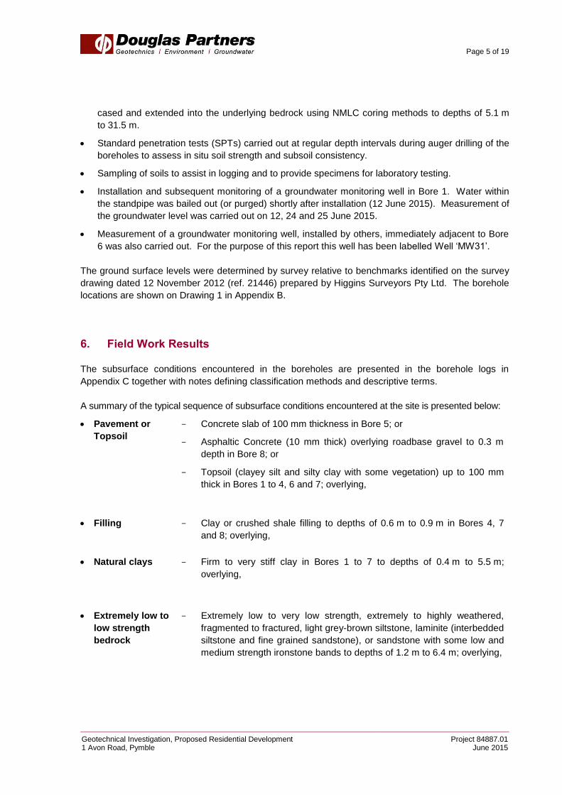
cased and extended into the underlying bedrock using NMLC coring methods to depths of 5.1 m
to 31.5 m.
Standard penetration tests (SPTs) carried out at regular depth intervals during auger drilling of the
boreholes to assess in situ soil strength and subsoil consistency.
Sampling of soils to assist in logging and to provide specimens for laboratory testing.
Installation and subsequent monitoring of a groundwater monitoring well in Bore 1. Water within
the standpipe was bailed out (or purged) shortly after installation (12 June 2015). Measurement of
the groundwater level was carried out on 12, 24 and 25 June 2015.
Measurement of a groundwater monitoring well, installed by others, immediately adjacent to Bore
6 was also carried out. For the purpose of this report this well has been labelled Well ‘MW31’.
The ground surface levels were determined by survey relative to benchmarks identified on the survey
drawing dated 12 November 2012 (ref. 21446) prepared by Higgins Surveyors Pty Ltd. The borehole
locations are shown on Drawing 1 in Appendix B.
6. Field Work Results
The subsurface conditions encountered in the boreholes are presented in the borehole logs in
Appendix C together with notes defining classification methods and descriptive terms.
A summary of the typical sequence of subsurface conditions encountered at the site is presented below:
Pavement or
Topsoil
- Concrete slab of 100 mm thickness in Bore 5; or
- Asphaltic Concrete (10 mm thick) overlying roadbase gravel to 0.3 m
depth in Bore 8; or
- Topsoil (clayey silt and silty clay with some vegetation) up to 100 mm
thick in Bores 1 to 4, 6 and 7; overlying,
Filling
- Clay or crushed shale filling to depths of 0.6 m to 0.9 m in Bores 4, 7
and 8; overlying,
Natural clays - Firm to very stiff clay in Bores 1 to 7 to depths of 0.4 m to 5.5 m;
overlying,
Extremely low to
low strength
bedrock
- Extremely low to very low strength, extremely to highly weathered,
fragmented to fractured, light grey-brown siltstone, laminite (interbedded
siltstone and fine grained sandstone), or sandstone with some low and
medium strength ironstone bands to depths of 1.2 m to 6.4 m; overlying,
Page 6 of 19
Geotechnical Investigation, Proposed Residential Development Project 84887.01 1 Avon Road, Pymble June 2015
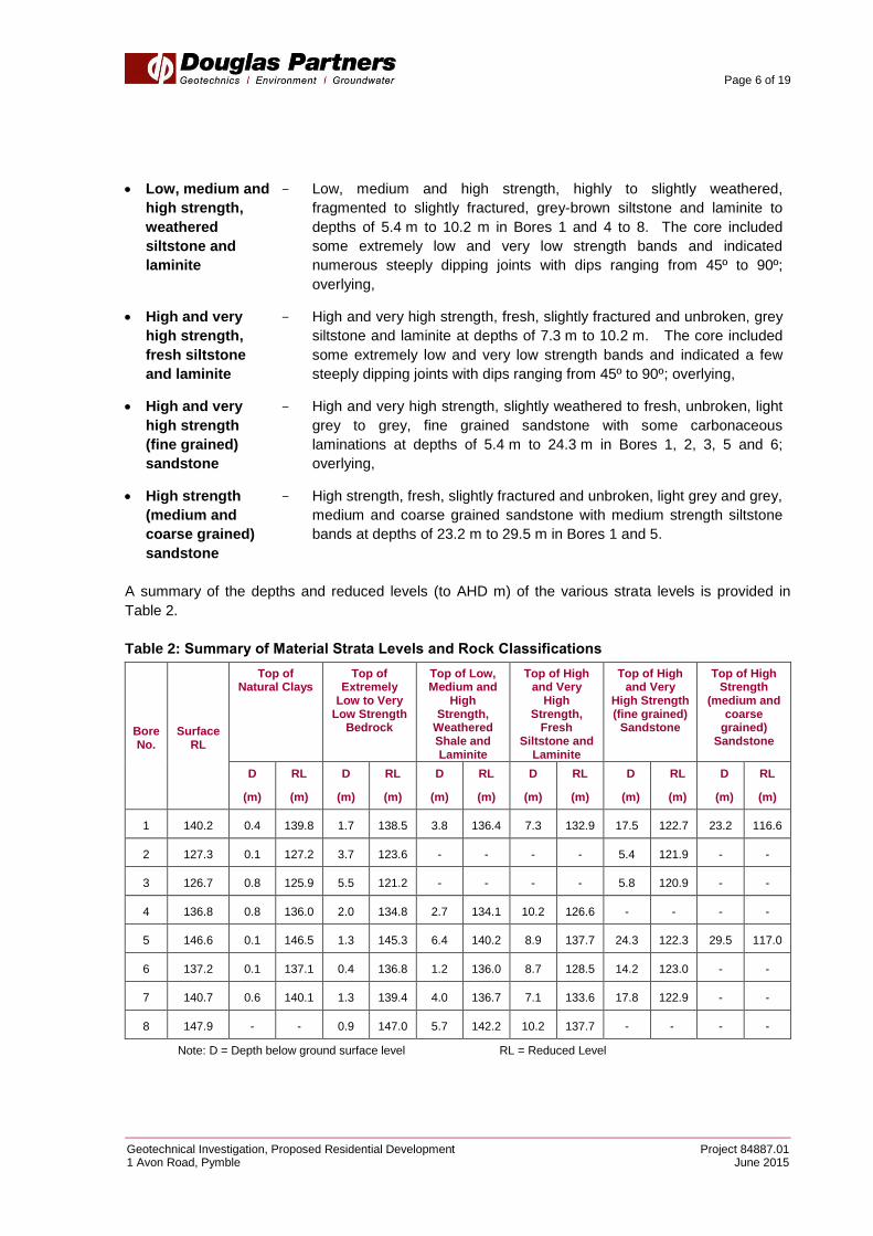
Low, medium and
high strength,
weathered
siltstone and
laminite
- Low, medium and high strength, highly to slightly weathered,
fragmented to slightly fractured, grey-brown siltstone and laminite to
depths of 5.4 m to 10.2 m in Bores 1 and 4 to 8. The core included
some extremely low and very low strength bands and indicated
numerous steeply dipping joints with dips ranging from 45º to 90º;
overlying,
High and very
high strength,
fresh siltstone
and laminite
- High and very high strength, fresh, slightly fractured and unbroken, grey
siltstone and laminite at depths of 7.3 m to 10.2 m. The core included
some extremely low and very low strength bands and indicated a few
steeply dipping joints with dips ranging from 45º to 90º; overlying,
High and very
high strength
(fine grained)
sandstone
- High and very high strength, slightly weathered to fresh, unbroken, light
grey to grey, fine grained sandstone with some carbonaceous
laminations at depths of 5.4 m to 24.3 m in Bores 1, 2, 3, 5 and 6;
overlying,
High strength
(medium and
coarse grained)
sandstone
- High strength, fresh, slightly fractured and unbroken, light grey and grey,
medium and coarse grained sandstone with medium strength siltstone
bands at depths of 23.2 m to 29.5 m in Bores 1 and 5.
A summary of the depths and reduced levels (to AHD m) of the various strata levels is provided in
Table 2.
Table 2: Summary of Material Strata Levels and Rock Classifications
Bore No.
Surface RL
Top of Natural Clays
Top of Extremely
Low to Very Low Strength
Bedrock
Top of Low, Medium and
High Strength,
Weathered Shale and Laminite
Top of High and Very
High Strength,
Fresh Siltstone and
Laminite
Top of High and Very
High Strength (fine grained)
Sandstone
Top of High Strength
(medium and coarse
grained) Sandstone
D
(m)
RL
(m)
D
(m)
RL
(m)
D
(m)
RL
(m)
D
(m)
RL
(m)
D
(m)
RL
(m)
D
(m)
RL
(m)
1 140.2 0.4 139.8 1.7 138.5 3.8 136.4 7.3 132.9 17.5 122.7 23.2 116.6
2 127.3 0.1 127.2 3.7 123.6 - - - - 5.4 121.9 - -
3 126.7 0.8 125.9 5.5 121.2 - - - - 5.8 120.9 - -
4 136.8 0.8 136.0 2.0 134.8 2.7 134.1 10.2 126.6 - - - -
5 146.6 0.1 146.5 1.3 145.3 6.4 140.2 8.9 137.7 24.3 122.3 29.5 117.0
6 137.2 0.1 137.1 0.4 136.8 1.2 136.0 8.7 128.5 14.2 123.0 - -
7 140.7 0.6 140.1 1.3 139.4 4.0 136.7 7.1 133.6 17.8 122.9 - -
8 147.9 - - 0.9 147.0 5.7 142.2 10.2 137.7 - - - -
Note: D = Depth below ground surface level RL = Reduced Level
Page 7 of 19
Geotechnical Investigation, Proposed Residential Development Project 84887.01 1 Avon Road, Pymble June 2015
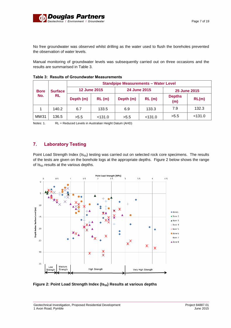
No free groundwater was observed whilst drilling as the water used to flush the boreholes prevented
the observation of water levels.
Manual monitoring of groundwater levels was subsequently carried out on three occasions and the
results are summarised in Table 3.
Table 3: Results of Groundwater Measurements
Bore No.
Surface RL
Standpipe Measurements – Water Level
12 June 2015 24 June 2015 25 June 2015
Depth (m) RL (m) Depth (m) RL (m) Depths
(m) RL(m)
1 140.2 6.7 133.5 6.9 133.3 7.9 132.3
MW31 136.5 >5.5 <131.0 >5.5 <131.0 >5.5 <131.0
Notes: 1. RL = Reduced Levels in Australian Height Datum (AHD)
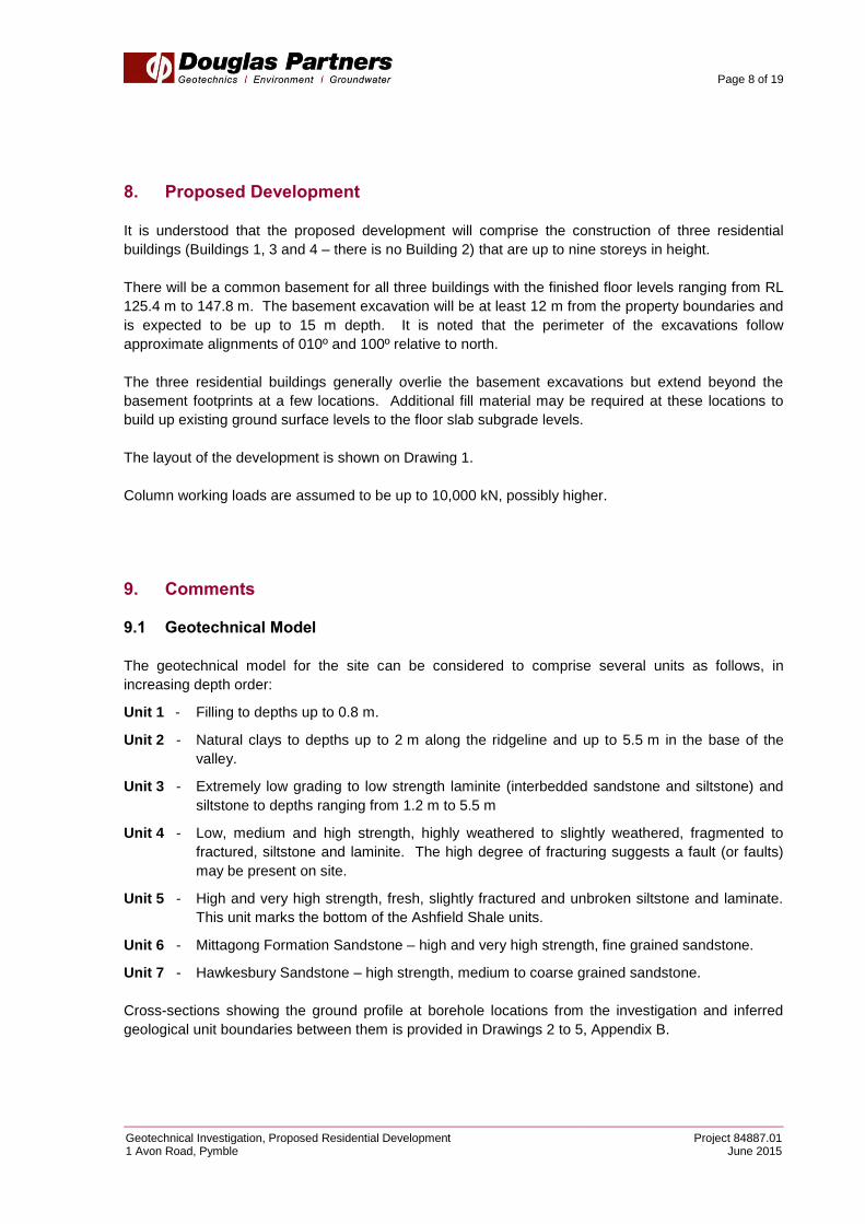
7. Laboratory Testing
Point Load Strength Index (Is50) testing was carried out on selected rock core specimens. The results
of the tests are given on the borehole logs at the appropriate depths. Figure 2 below shows the range
of Is50 results at the various depths.
Figure 2: Point Load Strength Index (Is50) Results at various depths
Page 8 of 19
Geotechnical Investigation, Proposed Residential Development Project 84887.01 1 Avon Road, Pymble June 2015
8. Proposed Development
It is understood that the proposed development will comprise the construction of three residential
buildings (Buildings 1, 3 and 4 – there is no Building 2) that are up to nine storeys in height.
There will be a common basement for all three buildings with the finished floor levels ranging from RL
125.4 m to 147.8 m. The basement excavation will be at least 12 m from the property boundaries and
is expected to be up to 15 m depth. It is noted that the perimeter of the excavations follow
approximate alignments of 010º and 100º relative to north.
The three residential buildings generally overlie the basement excavations but extend beyond the
basement footprints at a few locations. Additional fill material may be required at these locations to
build up existing ground surface levels to the floor slab subgrade levels.
The layout of the development is shown on Drawing 1.
Column working loads are assumed to be up to 10,000 kN, possibly higher.
9. Comments
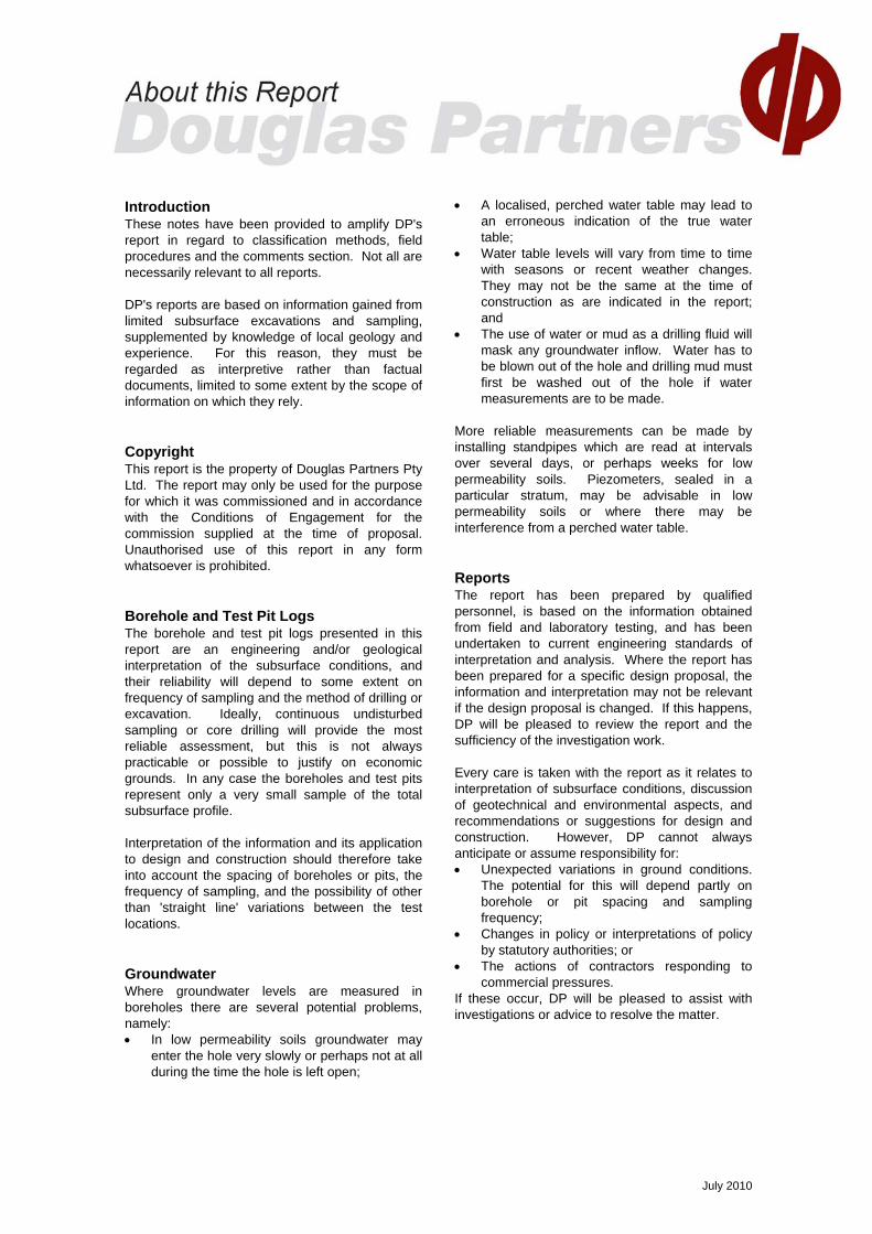
9.1 Geotechnical Model
The geotechnical model for the site can be considered to comprise several units as follows, in
increasing depth order:
Unit 1 - Filling to depths up to 0.8 m.
Unit 2 - Natural clays to depths up to 2 m along the ridgeline and up to 5.5 m in the base of the
valley.
Unit 3 - Extremely low grading to low strength laminite (interbedded sandstone and siltstone) and
siltstone to depths ranging from 1.2 m to 5.5 m
Unit 4 - Low, medium and high strength, highly weathered to slightly weathered, fragmented to
fractured, siltstone and laminite. The high degree of fracturing suggests a fault (or faults)
may be present on site.
Unit 5 - High and very high strength, fresh, slightly fractured and unbroken siltstone and laminate.
This unit marks the bottom of the Ashfield Shale units.
Unit 6 - Mittagong Formation Sandstone – high and very high strength, fine grained sandstone.
Unit 7 - Hawkesbury Sandstone – high strength, medium to coarse grained sandstone.
Cross-sections showing the ground profile at borehole locations from the investigation and inferred
geological unit boundaries between them is provided in Drawings 2 to 5, Appendix B.

Page 9 of 19
Geotechnical Investigation, Proposed Residential Development Project 84887.01 1 Avon Road, Pymble June 2015
It is noted that experience within the Ashfield Shale has indicated that there are dominant joint sets
present along 020º and 110º alignments (with up to 20 degree variations). These joint sets generally
dip between 30º to 70º.
The groundwater level appears to be at a level within the siltstone bedrock. It is likely that
groundwater seepage flows will occur within the upper weathered siltstone profiles. Groundwater
levels are likely to fluctuate, particularly after wet weather.
9.2 Excavation Conditions
Bulk excavation to RL 125.4 m for the proposed basement will encounter Geological Units 1 to 5.
Excavation within the Unit 1 and 2 soils and the Unit 3 weathered rock should be readily achievable by
bulldozer blade or an excavator with bucket attachment. Some light to medium ripping assistance or
the careful use of rock hammers, grinders or rock saws may be required for layers of higher strength
ironstone within Unit 3 rock.
Any excavation within Units 4 and 5 will require medium to heavy rock breaking equipment. Medium
strength rock is expected to have an unconfined compressive strength (UCS) of 6 – 20 MPa, high
strength rock is expected to have a UCS of 20 – 60 MPa and layers of very high strength siltstone with
a UCS of up to 90 MPa. Low productivity during excavation should be expected with such materials.
Rock breaking equipment will generally cause noise and vibrations that could be disturbing to
neighbours.
All excavated materials will need to be disposed in accordance with current DECC policies. Under the
Waste Avoidance and Resource Recovery Act (NSW EPA, 2001) a waste/fill receiving site must be
satisfied that materials received meet the environmental criteria for proposed land use. This includes
filling and virgin excavated natural materials (VENM), such as may be removed from site. The type
and extent of testing undertaken will depend on the final use or destination of the spoil, and
requirements of the receiving site.
It is anticipated that there may be some seepage of groundwater into the excavation. Such seepage
will need to be collected during construction by the judicious placement of drainage sumps and by
intermittent pumping or gravity discharge. At this stage, it is not possible to estimate the likely extent
and rate of seepage although it is anticipated from the extent of fracturing in the rock that it should be
readily handled by sump and pump measures. It is suggested that monitoring of flow during the early
phases of excavation below the groundwater table be undertaken to assess long term drainage
requirements.
Given that the groundwater seepage appears to be occurring in the weathered siltstones it is unlikely
that any drawdown of groundwater levels on neighbouring properties or the railway corridor will result
in settlement of neighbouring properties or infrastructure.
Noise and vibration will be associated with the excavation of bedrock materials. Further comments
regarding vibrations are included in Section 9.4.

Page 10 of 19
Geotechnical Investigation, Proposed Residential Development Project 84887.01 1 Avon Road, Pymble June 2015
9.3 Excavation Support
9.3.1 General
Vertical excavations in Units 1 to 5 will not be stable for any extended period of time due to either the
low shear strength of the soils/weathered rock (Units 1 to 3) or the high degree of fracturing of the
siltstone and laminite (Units 4 and 5).
Consideration has been given to vertical cuts in Units 4 and 5, however, given the high number of
steeply oriented joints (45° to 90°) observed within these units there is a high risk that an unstable
wedge could develop that would pose both an OH&S hazard to personnel on site and a sidewall
stability problem. Furthermore, the orientation of the edges of the excavations are almost parallel to
known steeply dipping joint sets that have been observed on numerous other projects in the Ashfield
Shale. If present, these joints could pose a significant risk to the stability of the sidewalls. Therefore it
is recommended that shoring walls extend the full depth of the excavation to below the bulk excavation
level (BEL).
The sidewalls of the basement excavation will therefore require temporary shoring support during
excavation and permanent retaining wall support as part of the final construction. The following
methods of support are recommended:
Temporary Batters (for excavations up to 3 m) - Temporary batter could be used to support
the sides of the excavation to a depth of up to 3 m, but will only where space permits. The
temporary batters will allow block retaining walls, or similar, to be constructed in front of the
batter. Further details regarding batter slopes are provided in Section 9.3.2.
Soldier pile/infill panel wall system (for excavations greater than 3 m) - for excavations
greater than 3 m depth, where batters cannot be provided, it is suggested that the excavation be
supported by temporary shoring and permanent retaining walls such as a soldier pile/infill panel
wall system. The soldier piles would generally be spaced at about 2 m to 3 m centres and should
be founded at least two pile diameters below the lowest excavation level (both bulk and detailed)
adjacent to the pile location. Soldier piles typically involve either bored piles or continuous flight
auger (CFA) piles.
At the completion of the each excavation lift, reinforced shotcrete infill panels should be
constructed. At no stage should progressive vertical excavation proceed beyond 2 m without infill
panel support being constructed. It is possible that adverse jointing may give rise to unstable
wedges and thus cause localised or even major instability in the exposed material. Regular
inspections by a geotechnical professional following each progressive lift of excavation would be
prudent to determine if any further stabilisation measures are required.
Strip drains should be installed behind the shotcrete of the soldier pile/infill panel wall system to
facilitate drainage and prevent build-up of water pressures behind the shoring.
Continuous pile wall (for excavations greater than 3 m) – for retaining walls requiring greater
stiffness then consideration could be given to installing a continuous pile wall. A continuous pile
wall involves the installation of either bored or CFA piles immediately adjacent to each other to
provide a continuous pile wall.
Page 11 of 19
Geotechnical Investigation, Proposed Residential Development Project 84887.01 1 Avon Road, Pymble June 2015
The presence of high and very high strength rock layers will require a drilling rig with sufficient torque
capacity to drill through these layers. The drilling contractor should confirm that the proposed drill rig
is of sufficient size and capacity to be able to confidently drill through these high and very high
strength layers.
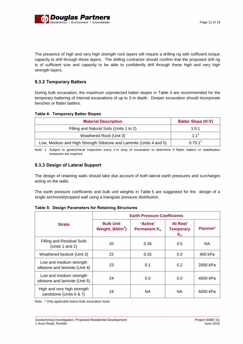
9.3.2 Temporary Batters
During bulk excavation, the maximum unprotected batter slopes in Table 4 are recommended for the
temporary battering of internal excavations of up to 3 m depth. Deeper excavation should incorporate
benches or flatter batters.
Table 4: Temporary Batter Slopes
Material Description Batter Slope (H:V)
Filling and Natural Soils (Units 1 to 2) 1.5:1
Weathered Rock (Unit 3) 1:11
Low, Medium and High Strength Siltstone and Laminite (Units 4 and 5) 0.75:11
Note: 1 Subject to geotechnical inspection every 2 m drop of excavation to determine if flatter batters or stabilisation
measures are required.
9.3.3 Design of Lateral Support
The design of retaining walls should take due account of both lateral earth pressures and surcharges
acting on the walls.
The earth pressure coefficients and bulk unit weights in Table 5 are suggested for the design of a
single anchored/propped wall using a triangular pressure distribution.
Table 5: Design Parameters for Retaining Structures
Strata
Earth Pressure Coefficients
Bulk Unit
Weight, (kN/m3)
‘Active’
Permanent Ka
‘At Rest’
Temporary
Ko
Passive*
Filling and Residual Soils
(Units 1 and 2) 20 0.35 0.5 NA
Weathered bedock (Unit 3) 22 0.25 0.3 400 kPa
Low and medium strength
siltstone and laminite (Unit 4) 23 0.1 0.2 2000 kPa
Low and medium strength
siltstone and laminite (Unit 5) 24 0.0 0.0 4000 kPa
High and very high strength
sandstone (Units 6 & 7) 24 NA NA 6000 kPa
Note: * Only applicable below bulk excavation level.

Page 12 of 19
Geotechnical Investigation, Proposed Residential Development Project 84887.01 1 Avon Road, Pymble June 2015
The active earth pressure coefficient, Ka, to be used for estimating soil pressures in Table 5 is for a
flexible wall allowing some lateral or outward “tilting” movement. Where it is necessary to limit
movement, it is suggested that the wall be designed for K0 (lateral earth pressure coefficients “at rest”)
conditions in combination with an analytical approach that considers the excavation and propping or
anchoring sequence.
The passive pressures provided in Table 5 are ultimate and an appropriate factor of safety should be
used to limit movement.
The design for lateral earth pressures for a multi-anchored wall system may be based on a uniform
rectangular earth pressure distribution. The following earth pressure distributions are considered
appropriate:
Units 1 to 3 = 4H (where H= height to be retained)
Units 1 to 3 = 8H (where lateral movements are to be limited)
Units 4 & 5 = 2H
Units 4 & 5 = 4H (where lateral movements are to be limited)
The design of temporary and permanent support will need to consider the possibility that 45° joints in
the siltstone and laminite (Units 4 and 5) will daylight near the base of the excavation leading to large
wedges of rock requiring support by the temporary and permanent retaining structures. Sufficient
anchoring of the shoring wall should be undertaken to prevent movements along 45° joints, even
though there is a low probability that a joint would run the full length and height of the excavation. It is
suggested that design be carried out such that the support system has a factor of safety of 1.2 against
the ultimate sliding force along the most unfavourable 45° joint.
The support system would typically comprise anchors spaced over the rock face. These anchors
should have their bond lengths behind the projected 45° line from the bulk excavation level and should
provide sufficient force to resist the movement of a wedge of rock projected at 45° from just below the
anchor to the ground surface. The frictional resistance of the wedge along the joint may be calculated
assuming an angle of friction of 20°. Regular rock-face inspections will be required during excavation
to determine whether the assumed factor of safety is adequate. Additional anchors may be required to
increase the factor of safety if large wedges are observed during excavation.
Wall design using the parameters given in Table 5 assume the following:
A level surface behind the top of the excavation;
Retaining walls will need to allow for hydrostatic pressures from the ground surface level if
drainage is not installed or maintained;
Construction traffic and other surcharge loadings (e.g. stacked materials) are not applied at the
crest of the retaining walls, for a distance of say 5 m behind the wall/shoring (otherwise the
resultant additional lateral loads need to be considered);
Passive resistance may be developed in Units 4 or 5 from beneath one pile diameter below the
bulk excavation level or below the base of any adjacent localised excavation. The passive
pressures calculated are ultimate values to which an appropriate factor of safety (say 3) should be

Page 13 of 19
Geotechnical Investigation, Proposed Residential Development Project 84887.01 1 Avon Road, Pymble June 2015
incorporated so as to limit the movement that otherwise is required to develop full passive
pressure.
The final or detailed design of retaining walls is normally undertaken using interactive computer
programs such as WALLAP, PLAXIS or FLAC, which can take due regard of soil-structure interaction
during the progressive stages of wall construction, anchoring and bulk excavation.
9.3.4 Ground Anchors
Temporary ground anchors will be required for the lateral restraint of most boundary shoring walls
greater than 3 m height (unless soil nails are used) until such time that the walls are permanently
strutted by the building floor slabs. The anchors should preferably have their bond length within
weathered (or stronger) rock.
Suggested allowable bond stresses for the design of temporary ground anchors for the support of
piled wall systems are given in Table 6.
Table 6: Bond Stresses for Anchor Design
Material Description Ultimate Bond Stress (kPa)
Weathered bedock (Unit 3) 100
Low and medium strength siltstone and laminite (Unit 4) 500
Low and medium strength siltstone and laminite (Unit 5) 1000
High and very high strength sandstone (Units 6 & 7) 3000
Ground anchors should be designed to have a free length that extends beyond an imaginary line
drawn upwards at an angle of 45° from the toe of the wall. The minimum free length should be 3 m.
After installation, each anchor should be proof loaded to 125% of the design working load and locked-
off at about 80% of the working load. Periodic checks should be carried out during the construction
phase to ensure that the lock-off load is maintained and not lost due to creep effects or other causes.
The above parameters are based on the assumption that the anchor holes are clean and thoroughly
flushed and that the grouting and other installation procedures carried out carefully and in accordance
with normal good anchoring practice. The successful anchoring contractor should be required to
demonstrate that design bond values are achievable with the proposed anchor construction methods.
If required, permanent ground anchors will require appropriate corrosion protection, anticipated to
include grouting and sheathing, to maintain the integrity of the anchor for its design life.
Approval should be sought from the adjacent property owners, where anchors extend below
neighbouring properties, roads or public access areas. Sydney Trains will not allow anchors under
their property.

Page 14 of 19
Geotechnical Investigation, Proposed Residential Development Project 84887.01 1 Avon Road, Pymble June 2015
9.3.5 Impacts on Rail Infrastructure
Lateral displacement along the north-eastern boundary, related to stress relief during basement
excavation, is expected to be less than that normally experienced for deep basements in the Sydney
area. The following factors are expected to contribute to the reduction in horizontal displacement that
the rail corridor is likely to experience during bulk excavation of the proposed basement:
The basement excavation is irregular in shape with return faces bracing the relatively short north-
east to south-west faces.
The site has a relatively deep soil and weathered rock cover.
The deep rail cutting into the shale has released some of the near surface locked-in stress.
The closest excavation is more than 14 m from the rail corridor.
The relatively deep gully to the southeast would have resulted in some stress relief.
The principal locked in stress in the Sydney region is north-south, therefore, east-west trending
excavation faces will experience larger displacements than north-south faces during excavation.
Measurements from numerous projects in Sydney suggests that long east-west trending faces
generally experience displacements at mid-face of 1 to 2 mm/m depth of excavation in low to medium
strength and stronger rock, with displacements reducing asymptotically away from the face.
Design drawings by Marchese Partners indicate the following for the buildings closest to the rail
corridor:
Building 1 – 13 m deep excavation set back 14 m from the rail corridor boundary.
Building 4 – 21.3 m deep excavation set back 22 m from the rail corridor boundary.
Borehole information indicates that these excavations will predominantly be in siltstone of medium
strength and stronger.
Based on this information the following worst case displacements, without anchors, are estimated:
Building 1 – 26 mm at the crest of Building 1 excavation and up to 6 mm at the rail track.
Building 4 – 43 mm at the crest of Building 4 excavation and up to 7 mm at the rail track.
These upper bound estimates are based on two dimensional measurements. The proposed
geometry, however, largely ignores the short face length of the proposed excavation and also the fact
that the excavation is not parallel or perpendicular to the adjacent railway line. Accordingly, the three
dimension configuration is likely to result in less stress relief. The proposed numerical modelling by
DP will be carried out in 3D and will model the effects of stress relief.
From an overall stability point of view retention support will be required. Reference to previous
comments in Section 9.3 should be made for advice regarding retention support.

Page 15 of 19
Geotechnical Investigation, Proposed Residential Development Project 84887.01 1 Avon Road, Pymble June 2015
9.4 Vibrations
During excavation it will be necessary to use appropriate methods and equipment to keep ground
vibrations within acceptable limits. The standards detailed in the Appendix D are considered
appropriate for management of ground vibrations.
Provisional Allowed Vibration Limit
From current information it is considered that the structures adjacent to the site can withstand vibration
levels higher than those required to maintain the comfort of their occupants. A human comfort
criterion is therefore indicated and the peak particle velocity in any direction i (PPVi), is proposed as
the control parameter. It is recommended that a Provisional Allowed Vibration Limit of 8.0 mm/sec
PPVi be set during normal working hours, at foundation level of the potentially affected building/s.
Excavation Plant
DP maintains a database of vibration trial results which can provide guidance for the selection of plant.
Trial data is dependent on site conditions and equipment, hence actual vibration levels may differ from
predictions and a specific trial is recommended at the commencement of rock excavation. The
database suggests that buffer distances within the ranges shown in Table 7 should be maintained
between excavation plant and adjacent buildings. These estimates should be examined in relation to
the distances between adjacent buildings and the proposed excavation footprint, in order to select
suitable plant.
Table 7: Approximate Buffer Distances for Excavation Plant
Excavation Plant Buffer Distance
(from trial maxima)1 (from trial averages)
Provisional Allowed Vibration Limit: 8 mm/s PPVi
Likely equivalent maximum Vector Sum PPV 11 mm/s VSPPV
Ripper on 20 t Excavator 2.5 m 0.9 m
Rock Hammer < 500 kg Operating Weight 5.6 m 2.2 m
Rock Hammer 501 – 1000 kg Operating Weight 6.3 m 2.6 m
Rock Hammer 1001 – 2000 kg Operating Weight 9.7 m 4.3 m
Rock Hammer >2000 kg Operating Weight 6.2 m 4.3 m
Note: 1 Smaller distances may be determined from individual trials, as indicated by those from trial averages

Page 16 of 19
Geotechnical Investigation, Proposed Residential Development Project 84887.01 1 Avon Road, Pymble June 2015
9.5 Foundations
Footing loads for the structure are assumed to be up to 10,000 kN (ultimate) for the multi-storey
building.
It is anticipated that both the weathered bedrock (extremely low to very low strength laminite and
siltstone - Unit 3) together with the low and medium strength siltstone (Units 4 and 5) will generally be
exposed at the bulk excavation levels. It is recommended that all footing loads be transferred to a
consistent stratum to achieve uniform founding conditions so as to avoid potential differential
settlement across the building. A combination of shallow foundations and piles are therefore
recommended over the basement area to uniformly found on the same rock layer.
The design of shallow or piled footings, for axial compression loading, may be based on the maximum
Limit State Design or Working Stress parameters given in Table 8.
Table 8: Maximum Foundation Design Parameters
Unit
Working Stress Design Values Limit State Design Values Elastic
Modulus
(MPa)
Allowable End
Bearing
Pressure (kPa)
Shaft Adhesion
(kPa)
Ultimate End
Bearing Pressure
(kPa)
Shaft Adhesion
(kPa)
Weathered Shale
(Unit 3) 700 70 3000 100 100
Low to Medium and
Medium Strength
Siltstone and Laminite
(Unit 4)
2500 250 20000 400 800
Low and medium
strength siltstone and
laminite (Unit 5)1
3500 350 30000 600 1000
High and very high
strength sandstone
(Units 6 & 7)2
6000 600 50000 1200 2000
Note: 1 Spoon testing of shallow footing will need to be carried out at least 30% of the footings across the site.
2. Increased design parameters may be appropriate following additional investigation of these units.
It should be noted that the allowable pressures for “Working Stress Design Values” given in Table 8
are based on a ‘limiting settlement’ of 1% of the footing width. Higher applied bearing pressures could
likely be adopted if a limit state approach to design is employed, provided that settlements remain
within the tolerable limits.
The design of footings is usually governed by settlement criteria and performance rather than the
ultimate bearing capacity or Ultimate Limit State condition. The Serviceability limit could be assessed,

Page 17 of 19
Geotechnical Investigation, Proposed Residential Development Project 84887.01 1 Avon Road, Pymble June 2015
for normal ‘static’ load cases, using the elastic modulus value given in Table 8. This modulus value is
appropriate for the anticipated working stress values or strain expected under serviceability loading.
Where the ultimate bearing pressures are adopted for Limit State Design of piles, a geotechnical
strength reduction factor (g) should be applied to the Ultimate geotechnical strength of the pile (Rd,ug),
in accordance with AS2159 – 2009 (Piling – Design and Installation). The g value adopted is
dependent on the level of confidence in the selected design parameters, design methods and
construction/installation methods. The level of site investigation and pile load testing are key inputs in
determining the g value. Given the coverage of boreholes over the site, an Individual Risk Rating
(IRR) of 3.0 is considered appropriate in accordance with Table 4.3.2(B) of AS 2159. This risk rating
should be combined with appropriate IRR’s for the design and installation of the piles to yield an
overall Average Risk Rating (ARR) and basic geotechnical strength reduction factor (gb). This factor
may be increased dependent on the amount of pile load testing employed, to give an g value that is
greater than gb.
Where shallow footings are located close to known subvertical excavations in rock it may be
necessary to downgrade the applied bearing pressure. The entire base should be below an imaginary
‘influence line’ projected upwards at 45° from the base of the subject excavation. Such situations
should be reviewed by the designer on a case-by-case basis.
The foundation design parameters presented in Table 8 assume that the shallow or pile footings are
clean at the base and free of loose debris prior to concrete placement.
All footings should be inspected by an experienced geotechnical professional to check the adequacy
of the foundation material. Spoon testing of a third of shallow footings founded in Unit 5 siltstone and
laminite.
9.6 Seismic Design
In accordance with Part 4 of the Structural design actions Standard, AS1170.4 – 2007, the site is
assessed to have a Site Sub-Soil Class of “Ce”.
9.7 Floor Slabs
The ground floor slab at the lowest level of the basement is expected to be used for carparking and
hence will probably only be lightly loaded. The base of the excavation will generally expose bedrock
which will provide adequate support for a slab-on-grade. The final surface should be trimmed and
scraped clean of debris etc. prior to pouring concrete.
On the western edge of the excavations, where natural clays are exposed at the bulk excavation level,
the floor slab should either be suspended on piles to be consistent with the floor slab to the east or an
articulation joint should be placed in the ground slab to allow for movements associated with the
shrink-swell or settlement of natural clays.
A gravel layer should be provided beneath the floor slab and should slope towards the sump pit to
allow sub-floor drainage. Given the high iron content of the siltstone, seepage is expected to result in
Page 18 of 19
Geotechnical Investigation, Proposed Residential Development Project 84887.01 1 Avon Road, Pymble June 2015
the formation of an iron-rich ‘gelatinous’ precipitate over the long-term, that can lead to the blockage of
drains and can cause problems for pumps. Adequate provision for access and maintenance of pumps
and drains should be incorporated into the design.
9.8 Subgrade Preparation
Where floor slabs beneath buildings, outside the footprint of excavations are proposed the following
subgrade preparation measures are recommended:
Remove all topsoil and filling materials.
Proof roll the exposed surface using a minimum 10 tonne smooth drum roller in non-vibration
mode. The surface should be rolled a minimum of six times with the last two passes observed
by an experienced geotechnical engineer to detect any ‘soft spots’.
Any heaving materials identified during proof rolling should be treated as directed by the
geotechnical engineer.
Any new filling should be placed in layers of 250 mm maximum loose thickness and compacted
to a dry density ratio between 98% and 102% relative to Standard compaction with moisture
contents maintained within 2% of Standard optimum moisture content.
Rockfill won from the excavation will general be suitable to re-use as fill up to the subgrade level
of floor slabs provided it is broken down to a well-graded material with a maximum particle size
of 100 mm. The rockfill won from Units 5 to 7 will generally be more difficult to breakdown than
the rockfill won from Units 3 and 4.
Density testing of the filling should be carried out in accordance with AS3798 “Guidelines for
Earthworks for Commercial and Residential Developments”.
Drainage measures should be included within all earthworks operations carried out on site.
9.9 Further Work
The following further work is recommended:
1) Three-dimensional numerical modelling to confirm the effect of the proposed development on the
neighbouring railway line.
2) Waste classification of material proposed to be transported off site in accordance with the
appropriate guidelines.
10. Limitations
Douglas Partners (DP) has prepared this report for this project at 1 Avon Road, Pymble in accordance
with DP’s proposal SYD150491-Rev1 dated 6 May 2015 and acceptance from Ausbao Pymble Pty Ltd
(AP) dated 18 May 2015. The work was carried out under DP’s conditions of Engagement. This
report is provided for the exclusive use of AP and their agents for the specific project and purpose as

Page 19 of 19
Geotechnical Investigation, Proposed Residential Development Project 84887.01 1 Avon Road, Pymble June 2015
described in the report. It should not be used for other projects or by a third party. DP has necessarily
relied upon information provided by the client and/or their agents.
The results provided in the report are considered to be indicative of the sub-surface conditions on the
site only to the depths investigated at the specific sampling and/or testing locations, and only at the
time the work was carried out. Sub-surface conditions can change abruptly due to variable geological
processes and also as a result of human influences. Such changes may occur after DP’s field testing
has been completed.
DP’s advice is based upon the conditions encountered during this investigation. The accuracy of the
advice provided by DP in this report may be affected by undetected variations in ground conditions
across the site between and beyond the sampling and/or testing locations. The advice may also be
limited by budget constraints imposed by others or by site accessibility.
This report must be read in conjunction with all the attached notes and should be kept in its entirety
without separation of individual pages or sections. DP cannot be held responsible for interpretations
or conclusions made by others unless they are supported by an expressed statement, interpretation,
outcome or conclusion stated in this report.
This report, or sections from this report, should not be used as part of a specification for a project,
without review and agreement by DP. This is because this report has been written as advice and
opinion rather than instructions for construction.
The contents of this report do not constitute formal design components such as are required, by the
Health and Safety Legislation and Regulations, to be included in a Safety Report specifying the
hazards likely to be encountered during construction and the controls required to mitigate risk. This
design process requires risk assessment to be undertaken, with such assessment being dependent
upon factors relating to likelihood of occurrence and consequences of damage to property and to life.
This, in turn, requires project data and analysis presently beyond the knowledge and project role
respectively of DP. DP may be able, however, to assist the client in carrying out a risk assessment of
potential hazards contained in the Comments section of this report, as an extension to the current
scope of works, if so requested, and provided that suitable additional information is made available to
DP. Any such risk assessment would, however, be necessarily restricted to the Geotechnical,
environmental and groundwater components set out in this report and to their application by the
project designers to project design, construction, maintenance and demolition.
Douglas Partners Pty Ltd

Appendix A
About this Report
July 2010
Introduction These notes have been provided to amplify DP's report in regard to classification methods, field procedures and the comments section. Not all are necessarily relevant to all reports. DP's reports are based on information gained from limited subsurface excavations and sampling, supplemented by knowledge of local geology and experience. For this reason, they must be regarded as interpretive rather than factual documents, limited to some extent by the scope of information on which they rely. Copyright This report is the property of Douglas Partners Pty Ltd. The report may only be used for the purpose for which it was commissioned and in accordance with the Conditions of Engagement for the commission supplied at the time of proposal. Unauthorised use of this report in any form whatsoever is prohibited. Borehole and Test Pit Logs The borehole and test pit logs presented in this report are an engineering and/or geological interpretation of the subsurface conditions, and their reliability will depend to some extent on frequency of sampling and the method of drilling or excavation. Ideally, continuous undisturbed sampling or core drilling will provide the most reliable assessment, but this is not always practicable or possible to justify on economic grounds. In any case the boreholes and test pits represent only a very small sample of the total subsurface profile. Interpretation of the information and its application to design and construction should therefore take into account the spacing of boreholes or pits, the frequency of sampling, and the possibility of other than 'straight line' variations between the test locations. Groundwater Where groundwater levels are measured in boreholes there are several potential problems, namely: • In low permeability soils groundwater may
enter the hole very slowly or perhaps not at all during the time the hole is left open;
• A localised, perched water table may lead to an erroneous indication of the true water table;
• Water table levels will vary from time to time with seasons or recent weather changes. They may not be the same at the time of construction as are indicated in the report; and
• The use of water or mud as a drilling fluid will mask any groundwater inflow. Water has to be blown out of the hole and drilling mud must first be washed out of the hole if water measurements are to be made.
More reliable measurements can be made by installing standpipes which are read at intervals over several days, or perhaps weeks for low permeability soils. Piezometers, sealed in a particular stratum, may be advisable in low permeability soils or where there may be interference from a perched water table. Reports The report has been prepared by qualified personnel, is based on the information obtained from field and laboratory testing, and has been undertaken to current engineering standards of interpretation and analysis. Where the report has been prepared for a specific design proposal, the information and interpretation may not be relevant if the design proposal is changed. If this happens, DP will be pleased to review the report and the sufficiency of the investigation work. Every care is taken with the report as it relates to interpretation of subsurface conditions, discussion of geotechnical and environmental aspects, and recommendations or suggestions for design and construction. However, DP cannot always anticipate or assume responsibility for: • Unexpected variations in ground conditions.
The potential for this will depend partly on borehole or pit spacing and sampling frequency;
• Changes in policy or interpretations of policy by statutory authorities; or
• The actions of contractors responding to commercial pressures.
If these occur, DP will be pleased to assist with investigations or advice to resolve the matter.

July 2010
Site Anomalies In the event that conditions encountered on site during construction appear to vary from those which were expected from the information contained in the report, DP requests that it be immediately notified. Most problems are much more readily resolved when conditions are exposed rather than at some later stage, well after the event. Information for Contractual Purposes Where information obtained from this report is provided for tendering purposes, it is recommended that all information, including the written report and discussion, be made available. In circumstances where the discussion or comments section is not relevant to the contractual situation, it may be appropriate to prepare a specially edited document. DP would be pleased to assist in this regard and/or to make additional report copies available for contract purposes at a nominal charge. Site Inspection The company will always be pleased to provide engineering inspection services for geotechnical and environmental aspects of work to which this report is related. This could range from a site visit to confirm that conditions exposed are as expected, to full time engineering presence on site.

Appendix B
Drawings

1
4
2
.
7
6
1
4
2
.
6
9
1
4
2
.
2
3
1
4
2
.
0
9
1
4
1
.
2
5
1
4
0
.
8
2
1
4
0
.
0
5
1
4
2
.
6
2
1
4
2
.
4
2
1
4
1
.
9
8
1
4
1
.
5
3
1
4
2
.
2
9
1
4
2
.
7
1
1
4
3
.
7
3
1
4
2
.
5
0
1
4
2
.
6
5
1
4
6
.
3
7
1
4
5
.
0
0
1
4
1
.
7
6
1
4
1
.
7
6
1
4
1
.
8
1
1
4
1
.
7
6
1
4
1
.
9
7
1
4
2
.
1
8
1
4
2
.
2
2
1
3
7
.
5
8
1
2
9
.
7
0
1
2
9
.
8
9
1
2
9
.
5
1
1
2
6
.
3
4
1
2
6
.
1
2
1
2
6
.
4
4
1
2
6
.
5
1
1
2
6
.
4
1
1
2
6
.
2
1
1
2
6
.
1
71
2
6
.
0
8
1
2
6
.
3
3
1
2
6
.
4
5
1
2
6
.
1
8
1
4
2
.
4
1
1
4
2
.
8
1
1
4
4
.
0
1
1
4
6
.
3
4
1
4
5
.
3
8
1
4
7
.
6
7
1
4
3
.
1
6
1
4
6
.
1
5
1
4
5
.
8
8
1
4
4
.
8
7
1
4
6
.
4
3
1
4
5
.
1
9
1
4
3
.
5
2
1
4
4
.
4
4
1
4
7
.
5
6
1
4
9
.
1
3
1
4
9
.
9
1
1
4
7
.
4
3
1
5
0
.
9
3
1
5
0
.
5
4
1
5
0
.
8
4
1
4
8
.
3
0
1
4
8
.
9
1
1
4
6
.
1
0
1
4
1
.
7
2
1
4
4
.
5
8
1
4
4
.
3
5
1
4
3
.
6
0
1
3
2
.
3
7
1
4
6
.
1
6
1
4
3
.
7
3
1
3
5
.
2
4
1
3
3
.
6
7
1
3
6
.
7
5
1
4
3
.
1
6
1
4
3
.
4
9
1
4
3
.
3
7
1
4
3
.
4
8
1
4
3
.
7
6
1
4
0
.
8
2
1
4
2
.
7
1
1
4
2
.
9
3
1
4
3
.
5
4
1
4
3
.
0
4
1
4
3
.
9
0
1
4
4
.
4
3
1
4
4
.
9
2
1
4
5
.
5
3
1
4
5
.
5
3
1
4
6
.
4
5
1
4
6
.
2
6
1
4
6
.
8
5
1
4
7
.
4
4
1
4
3
.
0
6
1
4
6
.
2
1
1
4
4
.
8
5
1
4
3
.
7
3
1
4
3
.
1
4
1
4
6
.
1
0
1
4
2
.
7
5
1
2
5
.
0
0
1
4
2
.
3
0
1
4
2
.
1
9
1
4
1
.
8
8
1
4
1
.
7
0
1
4
2
.
0
5
1
4
3
.
4
3
1
4
7
.
5
6
1
4
7
.
6
1
1
4
7
.
5
9
1
4
7
.
6
0
1
4
7
.
9
5
1
4
7
.
4
9
1
4
6
.
8
6
1
4
6
.
4
6
1
4
6
.
1
4
1
4
5
.
6
3
1
3
7
.
0
5
1
3
5
.
1
4
1
3
4
.
1
6
1
3
0
.
7
5
1
3
1
.
9
2
1
4
9
.
0
9
1
4
9
.
0
7
1
4
8
.
4
5
1
4
7
.
1
0
1
4
6
.
2
2
1
3
7
.
4
9
1
4
8
.
5
0
1
4
7
.
3
2
1
4
7
.
7
9
1
4
7
.
8
1
1
4
7
.
6
0
1
4
7
.
7
8
1
4
7
.
1
4
1
4
7
.
0
8
1
4
4
.
4
0
1
4
8
.
7
0
1
4
4
.
9
9
1
4
4
.
6
7
1
4
5
.
2
0
1
4
2
.
5
4
1
4
2
.
7
6
1
4
0
.
4
9
1
3
9
.
5
8
1
3
7
.
9
2
1
4
0
.
1
9
1
3
9
.
4
9
1
3
8
.
7
5
1
3
7
.
6
8
1
4
3
.
9
6
1
4
4
.
0
9
1
4
2
.
9
4
1
3
0
.
1
7
1
3
3
.
8
4
1
3
0
.
7
0
1
3
4
.
5
7
1
2
4
.
8
5
1
2
5
.
7
4
1
4
7
.
4
1
R
A
I
L
F
C
E
1
4
7
.
9
5
1
4
5
.
8
6
1
4
5
.
6
8
1
4
5
.
8
9
1
4
4
.
4
5
1
4
5
.
0
3
1
4
5
.
3
6
1
4
5
.
6
5
1
4
4
.
8
2
1
4
4
.
2
0
1
4
4
.
2
5
1
4
4
.
3
6
1
4
5
.
5
4
1
3
0
.
9
0
1
4
5
.
6
8
1
4
4
.
9
8
1
4
3
.
9
5
1
4
3
.
3
0
1
4
2
.
4
8
1
4
1
.
7
7
1
4
1
.
0
7
1
4
0
.
5
3
1
3
8
.
5
6
1
3
7
.
7
1
1
4
2
.
9
3
1
4
3
.
6
3
1
4
2
.
3
5
1
4
2
.
1
2
1
4
1
.
5
6
1
4
0
.
8
8
1
4
0
.
1
9
1
3
9
.
2
1
1
3
8
.
5
4
1
3
7
.
6
3
1
3
6
.
9
1
1
3
5
.
8
8
1
3
4
.
0
7
1
3
1
.
8
1
1
3
9
.
8
4
1
2
9
.
3
9
1
3
1
.
1
6
1
3
0
.
6
8
1
4
2
.
4
5
1
4
4
.
4
2
1
3
6
.
2
6
1
3
6
.
2
0
1
3
7
.
2
7
1
4
4
.
2
6
1
4
4
.
8
8
1
2
3
.
4
6
1
2
4
.
1
2
1
2
4
.
5
7
1
2
5
.
2
0
1
2
5
.
2
3
1
4
8
.
2
1
1
2
9
.
4
7
1
2
6
.
4
5
1
2
6
.
5
0
1
2
6
.
1
7
1
4
6
.
8
2
1
3
4
.
6
8
1
3
1
.
2
0
1
2
8
.
3
8
1
2
9
.
3
0
1
4
7
.
7
1
1
2
4
.
2
5
1
4
4
.
9
2
1
3
5
.
7
1
1
3
5
.
7
5
1
3
5
.
7
4
1
3
4
.
4
0
1
2
9
.
0
0
1
3
0
.
6
0
1
3
0
.
4
0
1
3
1
.
6
1
1
2
7
.
2
9
1
2
6
.
1
6
1
2
8
.
6
3
1
3
0
.
5
9
1
2
8
.
4
5
1
2
6
.
3
9
1
2
7
.
1
1
1
2
8
.
2
6
1
2
5
.
4
0
1
2
6
.
4
6
1
2
9
.
6
0
1
3
9
.
4
5
1
2
6
.
3
8
1
2
4
.
8
9
1
2
4
.
1
4
1
2
3
.
9
0
1
4
3
.
9
3
1
4
2
.
8
4
1
4
8
.
5
6
1
4
4
.
6
0
1
4
6
.
4
9
1
4
7
.
8
6
1
4
7
.
7
4
1
4
3
.
7
3
1
4
4
.
6
8
1
4
4
.
0
2
1
4
7
.
8
8
1
4
7
.
8
9
1
4
7
.
1
6
1
4
7
.
0
4
1
4
6
.
4
0
1
4
1
.
1
4
1
4
4
.
3
8
1
4
2
.
4
6
1
4
4
.
0
3
1
4
5
.
0
8
1
4
4
.
7
2
1
4
4
.
4
7
1
4
5
.
8
8
1
4
5
.
2
1
1
4
6
.
3
6
1
4
6
.
1
0
1
4
5
.
8
2
1
4
4
.
2
4
1
4
4
.
0
8
1
4
4
.
0
2
1
4
4
.
1
4
1
4
4
.
1
7
1
4
4
.
4
4
1
4
4
.
3
8
1
4
1
.
6
5
1
4
6
.
4
3
1
4
6
.
0
6
1
4
6
.
4
6
1
4
7
.
5
8
1
4
0
.
2
0
1
4
1
.
3
0
1
4
0
.
3
1
1
4
2
.
0
0
1
4
0
.
9
0
1
4
3
.
8
7
1
4
3
.
9
3
1
4
3
.
5
0
1
4
1
.
7
0
1
4
2
.
1
9
1
4
1
.
9
1
1
4
3
.
0
7
1
4
4
.
0
0
1
4
6
.
6
1
1
4
3
.
8
7
1
2
6
.
4
3
1
2
5
.
6
3
1
2
9
.
0
2
1
3
4
.
2
1
1
3
7
.
0
2
1
4
5
.
9
1
1
4
7
.
3
0
1
4
6
.
1
5
1
4
7
.
7
7
1
4
7
.
7
4
1
4
5
.
3
9
1
4
3
.
9
0
1
4
0
.
2
7
1
4
4
.
1
1
1
2
9
.
9
4
1
3
2
.
2
4
1
2
9
.
1
6
1
4
4
.
5
0
1
4
5
.
4
8
1
4
6
.
3
8
1
4
3
.
3
7
1
4
5
.
0
4
1
4
3
.
9
5
1
4
6
.
8
2
1
4
2
.
2
2
1
4
2
.
7
5
1
4
3
.
1
2
1
4
4
.
9
1
1
4
6
.
1
0
1
4
7
.
4
5
1
4
7
.
1
1
1
4
6
.
6
6
1
4
3
.
6
0
1
4
3
.
3
6
1
4
2
.
8
9
1
4
2
.
8
7
1
4
2
.
9
1
1
4
5
.
1
8
1
4
7
.
0
0
1
4
7
.
0
0
1
4
2
.
5
9
1
4
0
.
4
3
1
4
1
.
3
6
1
4
1
.
1
5
139.42
1
3
9
.
2
6
1
4
1
.
8
7
1
4
2
.
8
6
1
4
2
.
8
2
1
4
1
.
2
4
1
4
1
.
5
0
1
4
0
.
7
5
1
4
0
.
4
8
1
3
9
.
9
7
1
3
8
.
8
9
1
3
7
.
3
4
1
3
7
.
3
3
1
3
8
.
6
8
1
4
3
.
4
7
1
4
2
.
3
4
1
3
5
.
3
2
1
3
5
.
7
3
1
3
7
.
3
4
1
3
7
.
2
2
1
3
4
.
8
2
1
3
9
.
4
4
1
4
0
.
7
5
1
4
0
.
1
4
1
3
9
.
4
9
1
3
8
.
3
7
1
3
8
.
0
7
1
3
8
.
4
9
1
3
8
.
9
9
1
3
7
.
0
1
1
3
6
.
6
5
1
3
6
.
5
0
1
4
0
.
8
5
1
4
1
.
2
1
1
4
1
.
0
8
1
4
1
.
6
9
1
3
8
.
1
9
1
3
7
.
8
0
1
3
7
.
3
7
1
3
7
.
4
5
1
3
7
.
7
7
1
3
7
.
8
4
1
3
7
.
3
3
1
4
0
.
0
2
1
3
9
.
8
0
1
4
0
.
6
3
1
3
9
.
4
1
1
3
8
.
3
7
1
3
8
.
3
0
1
4
1
.
1
3
1
4
1
.
2
9
1
4
0
.
1
5
1
4
0
.
8
2
1
3
5
.
4
7
1
3
5
.
9
3
1
4
1
.
2
2
1
3
9
.
9
3
1
3
7
.
5
5
1
4
2
.
9
4
1
4
2
.
8
2
1
4
2
.
5
6
1
4
1
.
9
3
1
4
1
.
3
0
1
3
8
.
9
9
1
3
7
.
3
2
1
3
5
.
4
7
1
3
5
.
7
8
1
3
5
.
3
8
1
4
0
.
9
2
1
3
6
.
4
4
1
3
6
.
3
5
1
3
5
.
5
3
1
3
9
.
3
5
1
3
8
.
7
5
1
3
8
.
8
3
1
3
6
.
5
4
1
3
6
.
0
4
1
3
4
.
4
9
1
3
6
.
1
3
1
3
7
.
1
5
1
2
7
.
2
8
1
2
7
.
5
9
1
2
7
.
8
4
1
2
7
.
9
8
1
2
8
.
3
3
1
2
8
.
1
9
1
2
7
.
0
8
1
2
7
.
7
2
1
2
9
.
0
0
1
2
8
.
7
2
1
2
8
.
7
0
1
2
8
.
6
1
1
2
4
.
3
5
1
2
5
.
6
1
1
2
4
.
7
9
1
2
5
.
8
8
1
2
4
.
5
0
1
3
4
.
9
4
1
3
7
.
5
8
1
3
8
.
9
2
1
3
9
.
0
0
1
4
1
.
5
0
1
3
8
.
7
3
1
4
0
.
4
5
1
4
0
.
7
9
1
3
9
.
6
5
1
3
6
.
8
9
1
3
5
.
2
4
1
2
9
.
3
6
1
2
8
.
6
8
1
2
9
.
8
0
1
3
0
.
3
2
1
2
9
.
9
8
1
3
8
.
4
1
1
3
8
.
5
0
1
4
2
.
4
8
1
3
0
.
0
8
1
3
2
.
6
5
1
3
0
.
3
6
1
3
0
.
8
6
1
2
8
.
5
7
1
2
9
.
3
6
1
2
7
.
0
2
1
2
9
.
8
6
1
2
9
.
5
8
1
2
9
.
5
1
1
3
3
.
3
4
1
2
8
.
0
6
1
2
8
.
6
2
1
2
7
.
8
3
1
3
0
.
9
7
1
2
5
.
0
0
1
2
5
.
8
0
1
2
9
.
8
2
1
3
0
.
6
5
1
3
0
.
7
9
1
2
8
.
7
4
1
3
0
.
0
0
1
3
7
.
1
5
1
3
0
.
6
4
1
2
4
.
0
0
1
2
4
.
9
51
2
4
.
6
1
1
2
4
.
5
3
1
2
4
.
7
6
1
2
9
.
4
8
1
3
2
.
3
0
1
3
4
.
9
7
1
3
0
.
4
5
1
3
5
.
1
6
1
3
9
.
3
1
1
3
7
.
4
4
1
4
0
.
6
0
1
4
0
.
0
7
1
3
7
.
6
8
1
3
8
.
6
5
1
4
0
.
0
4
1
4
2
.
7
2
1
4
3
.
1
8
1
4
6
.
8
8
1
4
4
.
6
0
1
4
0
.
3
0
1
4
7
.
8
6
1
4
9
.
4
4
1
4
9
.
5
7
1
4
9
.
9
3
1
5
0
.
4
8
1
4
5
.
8
2
1
4
6
.
0
0
1
4
7
.
0
7
1
4
5
.
6
2
1
4
5
.
0
0
1
4
7
.
0
7
1
4
1
.
7
0
1
4
1
.
8
2
1
4
4
.
3
2
1
4
3
.
5
0
1
4
3
.
4
4
1
4
2
.
4
3
1
3
9
.
4
3
1
3
8
.
5
2
1
4
0
.
0
7
1
3
9
.
6
4
1
4
0
.
3
5
1
4
3
.
1
8
1
4
2
.
7
8
1
4
3
.
4
8
1
4
3
.
6
0
1
4
2
.
7
1
1
4
1
.
0
8
1
4
2
.
5
7
1
4
2
.
7
9
1
4
3
.
3
2
1
4
3
.
5
6
1
4
5
.
0
0
1
4
7
.
5
8
1
3
8
.
9
2
1
4
1
.
5
6
1
4
2
.
7
4
1
4
1
.
4
9
1
4
7
.
8
0
1
4
7
.
6
8
1
4
5
.
4
3
1
4
6
.
7
7
1
4
8
.
6
1
1
4
9
.
6
9
1
4
9
.
0
9
1
4
8
.
1
1
1
4
5
.
2
7
1
4
6
.
2
5
1
4
8
.
3
3
1
4
9
.
9
7
1
5
0
.
0
9
1
5
0
.
0
2
1
4
7
.
7
2
1
4
6
.
7
7
1
5
0
.
0
5
1
3
8
.
2
0
1
3
9
.
3
0
1
3
8
.
8
5
1
3
9
.
1
0
1
4
1
.
1
9
1
3
9
.
8
9
1
3
6
.
4
1
1
3
5
.
2
1
1
2
3
.
8
5
1
4
7
.
5
0
1
2
8
.
0
3
1
3
6
.
1
1
1
4
4
.
4
1
1
4
2
.
7
2
1
3
6
.
9
2
1
4
9
.
1
4
A
V
O
N
R
O
A
D
1
4
1
.
3
9
1
4
1
.
6
3
1
4
1
.
2
1
1
4
0
.
3
2
1
4
7
.
6
6
1
4
8
.
3
9
1
4
8
.
9
2
1
2
8
.
7
5
1
3
1
.
2
4
D P 5 8 3 8 0 3
1
D P 2 0 5 5 0 4
2
D P 5 8 3 8 0 3
2
D P 3 8 8 4 0 7
A
D P 2 0 5 5 0 4
1
R
ID
G
E
R
.L
1
4
5
.1
3
R
I
D
G
E
R
.
L
1
5
0
.
3
0
1
3
4
.
4
9
1
3
6
.
1
3
1
3
7
.
1
5
T
R
E
E
1
3
3
.
0
6
T
R
E
E
1
3
1
.
7
8
T
R
E
E
1
3
6
.
0
0
T
R
E
E
1
3
6
.
5
5
T
R
E
E
1
3
7
.
2
7
T
R
E
E
1
3
7
.
3
8
1
3
5
.
8
1
1
3
5
.
7
0
1
3
6
.
7
0
1
3
6
.
3
8
1
3
6
.
6
9
137.32
1
3
6
.
8
3
1
3
6
.
7
5
1
3
7
.
2
7
P
A
L
M
1
3
7
.
3
7
1
3
6
.
6
9
1
3
7
.
2
8
1
3
7
.
2
8
1
3
5
.
6
1
R
ID
G
E
R
.L
1
4
2
.3
1
U
/S
G
U
T
T
E
R
R
.L
1
3
9
.0
0
U
/S
G
U
T
T
E
R
R
.L
1
4
0
.4
5
U
/S
G
U
T
T
E
R
R
.L
1
4
2
.9
0
U
/S
G
U
T
T
E
R
R
.L
1
4
2
.9
0
R
ID
G
E
R
.L
1
4
5
.0
5
1
4
5
.5
4
1
4
4
.5
9
145.54
1
4
5
.4
0
1
4
3
.6
3
1
4
3
.6
5
1
4
3
.9
7
1
4
6
.1
1
1
4
6
.1
0
1
4
6
.1
0
1
4
6
.0
9
T
R
E
E
1
4
4
.7
6
T
R
E
E
1
4
5
.0
3
T
R
E
E
1
4
5
.4
5
T
R
E
E
1
4
5
.8
0
L
E
V
E
L
R
.
L
1
4
3
.
9
5
F
L
O
O
R
U
/
S
G
U
T
T
E
R
R
.
L
1
4
8
.
1
3
U
/
S
G
U
T
T
E
R
R
.
L
1
4
8
.
1
3
L
E
V
E
L
R
.
L
1
4
5
.
6
8
F
L
O
O
R
L
E
V
E
L
R
.
L
1
4
5
.
6
8
F
L
O
O
R
LE
V
E
L
R
.L
137.4
8
F
L
O
O
R
R
ID
G
E
R
.L
1
4
3
.8
5
R
ID
G
E
R
.L
1
4
3
.8
5
R
ID
G
E
R
.L
1
4
3
.8
5
R
ID
G
E
R
.L
1
4
1
.9
5
RID
GE
R
.L
15
5.1
0
RIDGE R.L155.10
RIDGE R.L155.10
RIDGE R.L157.90
142.25
137.64
TR
EE
133.24
129.75
135.47
129.70
GU
M
GU
M
GU
M
130.00
GU
M
134.31
GU
M
131.58
127.70
128.94
128.61
PA
LM
131.04
GU
M
GU
M
GU
M
GU
M
GU
M
TR
EE
TR
EE
TR
EE
CO
NC
14
1.7
6
CO
NC
14
1.8
1
14
2.6
0
14
3.3
4
KB
14
2.8
2
SIG
N
142.77
SIG
N
14
2.7
7
SIG
N
14
2.7
5
SIG
N
14
2.6
8
SIG
N
14
2.8
1
SIG
N
14
2.2
2
14
2.3
2
142.50
1
4
3
.6
1
1
4
3
.5
7
1
4
3
.4
5
1
4
3
.2
9
1
4
2
.9
5
1
4
2
.6
2
1
4
2
.5
0
1
4
2
.2
1
1
4
1
.7
9
1
4
3
.8
0
1
4
3
.6
9
1
4
3
.5
8
1
4
3
.2
5
1
4
2
.8
4
1
4
3
.7
3
1
4
5
.5
3
1
4
5
.5
3
146.11
T
O
P
O
F
W
A
L
L
R
.
L
.
1
4
4
.
5
4
S
T
R
E
E
1
4
2
.6
8
S
T
R
E
E
1
4
3
.0
9
T
R
E
E
1
4
4
.5
1
1
4
4
.8
2
1
4
6
.6
2
1
4
3
.6
0
1
4
5
.2
9
143.14
1
4
4
.3
4
1
4
3
.7
5
1
4
3
.7
8
1
4
3
.8
0
1
4
3
.8
2
143.83
1
4
5
.4
3
1
4
5
.4
1
1
4
4
.5
0
144.19
1
4
4
.1
9
1
4
4
.4
3
1
4
4
.5
2
1
4
4
.5
9
1
4
4
.8
1
1
4
5
.0
8
1
4
5
.2
5
1
4
5
.3
6
1
4
4
.9
8
145.37
145.45
1
4
6
.0
2
1
4
6
.1
0
1
4
5
.8
0
1
4
5
.5
4
1
4
5
.7
3
1
4
5
.
9
6
1
4
5
.3
3
1
4
5
.9
6
1
4
6
.1
3
1
4
6
.3
4
145.97
145.98
1
4
5
.8
7
T
O
P
O
F
W
A
L
L
R
.
L
.
1
4
4
.
4
4
T
O
P
O
F
W
A
L
L
R
.
L
.
1
4
4
.
2
7
T
O
P
O
F
W
A
L
L
R
.
L
.
1
4
3
.
9
3
T
O
P
O
F
W
A
L
L
R
.
L
.
1
4
3
.
6
9
T
O
P
O
F
W
A
L
L
R
.
L
.
1
4
2
.
3
4
T
O
P
O
F
W
A
L
L
R
.
L
.
1
4
2
.
6
5
T
O
P
O
F
W
A
L
L
R
.
L
.
1
4
6
.
2
6
T
O
P
O
F
W
A
L
L
R
.
L
.
1
4
6
.
6
0
T
O
P
O
F
W
A
L
L
R
.
L
.
1
4
6
.
3
7
T
O
P
O
F
W
A
L
L
R
.
L
.
1
4
6
.
1
0
T
O
P
O
F
W
A
L
L
R
.
L
.
1
4
7
.
3
2
T
O
P
O
F
W
A
L
L
R
.
L
.
1
4
5
.
7
7
T
R
E
E
0
.
8
Ø
,
1
3
S
P
,
1
8
H
P
I
N
E
T
R
E
E
1
.
0
Ø
,
1
0
S
P
,
2
5
H
T
R
E
E
0
.
9
Ø
,
1
5
S
P
,
1
8
H
P
I
N
E
T
R
E
E
0
.
6
Ø
,
7
S
P
,
2
0
H
U/S
G
UT
TE
R R
.L
15
1.2
9
U/S
G
UT
TE
R
R.L
15
1.9
0
U/S
G
UT
TE
R R
.L
. 1
51
.9
0
R.L
15
1.9
0
U/S GUTTER
R.L151.90
147.65
147.32
1
2
3
4
5
6
7
8
X
MW31
Location of Boreholes
Proposed Residential Development
1 Avon Road, PYMBLE
LEGEND
Borehole location
Approximate extent of bulk excavation
Approximate extent of building
Groundwater well - EIS2015
NOTE: 1. Base drawing from Higgins Surveyors Pty Ltd
(Ref. 21446, dated 12.11.2012)
2. Test locations are approximate only and are
shown with reference to existing site features.
125.40
147.30
144.20
131.60
128.50
144.20
138.00
134.20
139.20
RAILWAY CORRIDOR
Geotechnical Cross Section A-A'
0 5 10 20
1:500 @ A3
30 40 50m15
BUILDING1
BUILDING3
BUILDING4
x
22m
14m
P:\8
48
87
.0
1 - A
vo
n R
d P
ym
ble
G
eo
te
ch
In
ve
stig
atio
n\7
.0
D
ra
win
gs\7
.2
O
ut\8
48
87
.0
1-1
.d
wg
, 1
/0
7/2
01
5 1
0:5
6:0
0 A
M, D
WG
T
o P
DF
.p
c3
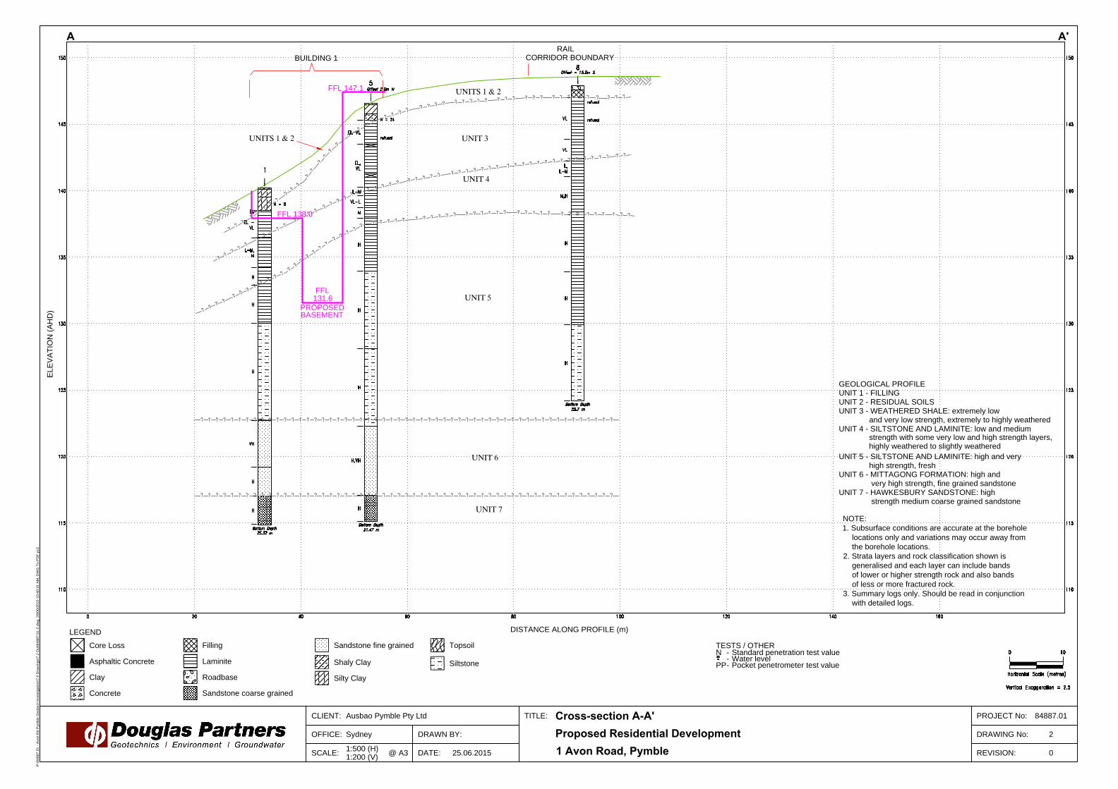
OFFICE: DRAWN BY:
CLIENT: TITLE: PROJECT No:
DRAWING No:
REVISION:25.06.2015
2
ELE
VA
TIO
N (A
HD
)
Core Loss
Asphaltic Concrete
Clay
1:500 (H)
1:200 (V)
SCALE: @ A3
Sydney
DATE:
TESTS / OTHER
LEGEND
DISTANCE ALONG PROFILE (m)
Concrete
Filling
Laminite
Roadbase
Sandstone coarse grained
Sandstone fine grained
Shaly Clay
Silty Clay
Topsoil
Proposed Residential Development
A A'
1 Avon Road, Pymble
Ausbao Pymble Pty Ltd
Cross-section A-A'
84887.01
N - Standard penetration test value
- Water level
PP- Pocket penetrometer test value
BUILDING 1
UNITS 1 & 2
CORRIDOR BOUNDARY
UNIT 3
UNIT 4
UNIT 5
UNIT 6
UNIT 7
GEOLOGICAL PROFILE
UNIT 1 - FILLING
UNIT 2 - RESIDUAL SOILS
UNIT 3 - WEATHERED SHALE: extremely low
and very low strength, extremely to highly weathered
UNIT 4 - SILTSTONE AND LAMINITE: low and medium
strength with some very low and high strength layers,
UNIT 5 - SILTSTONE AND LAMINITE: high and very
high strength, fresh
UNIT 6 - MITTAGONG FORMATION: high and
very high strength, fine grained sandstone
UNIT 7 - HAWKESBURY SANDSTONE: high
strength medium coarse grained sandstone
FFL 138.0
FFL
131.6
0
NOTE:
1. Subsurface conditions are accurate at the borehole
locations only and variations may occur away from
the borehole locations.
2. Strata layers and rock classification shown is
generalised and each layer can include bands
of lower or higher strength rock and also bands
of less or more fractured rock.
3. Summary logs only. Should be read in conjunction
with detailed logs.
FFL 147.1 UNITS 1 & 2
RAIL
PROPOSED
BASEMENT
highly weathered to slightly weathered
Siltstone
P:\8
48
87
.0
1 - A
vo
n R
d P
ym
ble
G
eo
te
ch
In
ve
stig
atio
n\7
.0
D
ra
win
gs\7
.2
O
ut\8
48
87
.0
1-2
.d
wg
, 2
9/0
6/2
01
5 1
0:4
0:3
1 A
M, D
WG
T
o P
DF
.p
c3
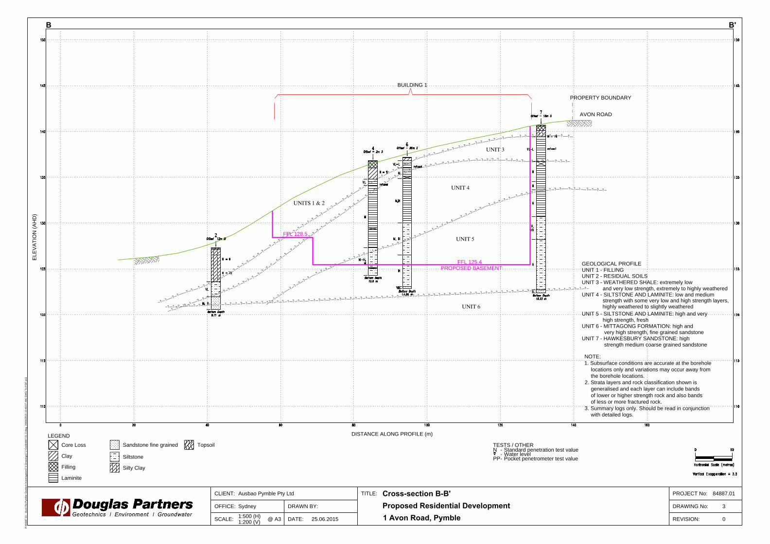
OFFICE: DRAWN BY:
CLIENT: TITLE: PROJECT No:
DRAWING No:
REVISION:25.06.2015
3
ELE
VA
TIO
N (A
HD
)
Core Loss
Clay
Filling
1:500 (H)
1:200 (V)
SCALE: @ A3
Sydney
DATE:
TESTS / OTHER
LEGEND
DISTANCE ALONG PROFILE (m)
Laminite
Sandstone fine grained
Siltstone
Silty Clay
Topsoil
Proposed Residential Development
B B'
1 Avon Road, Pymble
Ausbao Pymble Pty Ltd
Cross-section B-B'
84887.01
N - Standard penetration test value
- Water level
PP- Pocket penetrometer test value
UNITS 1 & 2
UNIT 3
UNIT 4
UNIT 5
UNIT 6
FFL 128.5
FFL 125.4
0
PROPOSED BASEMENT
BUILDING 1
AVON ROAD
PROPERTY BOUNDARY
GEOLOGICAL PROFILE
UNIT 1 - FILLING
UNIT 2 - RESIDUAL SOILS
UNIT 3 - WEATHERED SHALE: extremely low
and very low strength, extremely to highly weathered
UNIT 4 - SILTSTONE AND LAMINITE: low and medium
strength with some very low and high strength layers,
UNIT 5 - SILTSTONE AND LAMINITE: high and very
high strength, fresh
UNIT 6 - MITTAGONG FORMATION: high and
very high strength, fine grained sandstone
UNIT 7 - HAWKESBURY SANDSTONE: high
strength medium coarse grained sandstone
NOTE:
1. Subsurface conditions are accurate at the borehole
locations only and variations may occur away from
the borehole locations.
2. Strata layers and rock classification shown is
generalised and each layer can include bands
of lower or higher strength rock and also bands
of less or more fractured rock.
3. Summary logs only. Should be read in conjunction
with detailed logs.
highly weathered to slightly weathered
P:\8
48
87
.0
1 - A
vo
n R
d P
ym
ble
G
eo
te
ch
In
ve
stig
atio
n\7
.0
D
ra
win
gs\7
.2
O
ut\8
48
87
.0
1-3
.d
wg
, 2
9/0
6/2
01
5 1
0:4
0:0
7 A
M, D
WG
T
o P
DF
.p
c3
OFFICE: DRAWN BY:
CLIENT: TITLE: PROJECT No:
DRAWING No:
REVISION:26.06.2015
4
ELE
VA
TIO
N (A
HD
)
Core Loss
Clay
Concrete
1:500 (H)
1:200 (V)
SCALE: @ A3
Sydney
DATE:
TESTS / OTHER
LEGEND
DISTANCE ALONG PROFILE (m)
Filling
Laminite
Sandstone coarse grained
Sandstone fine grained
Shaly Clay
Siltstone
Silty Clay
Topsoil
Proposed Multi-Unit Building Development
C C'
1 Avon Road, Pymble
Ausbao Pymble Pty Ltd
Cross-section C-C'
84887.01
N Standard penetration test value
Water level
PP Pocket penetrometer test value
BUILDING 4
UNIT 3
UNIT 4
UNIT 5
UNIT 6
UNIT 7
GEOLOGICAL PROFILE
UNIT 1 - FILLING
UNIT 2 - RESIDUAL SOILS
UNIT 3 - WEATHERED SHALE: extremely low
and very low strength, extremely to highly weathered
UNIT 4 - SILTSTONE AND LAMINITE: low and medium
strength with some very low and high strength layers,
UNIT 5 - SILTSTONE AND LAMINITE: high and very
high strength, fresh
UNIT 6 - MITTAGONG FORMATION: high and
very high strength, fine grained sandstone
UNIT 7 - HAWKESBURY SANDSTONE: high
strength medium coarse grained sandstone
NOTE:
1. Subsurface conditions are accurate at the borehole
locations only and variations may occur away from
the borehole locations.
2. Strata layers and rock classification shown is
generalised and each layer can include bands
of lower or higher strength rock and also bands
of less or more fractured rock.
3. Summary logs only. Should be read in conjunction
with detailed logs.
FFL 131.6
UNITS 1 & 2
highly weathered to slightly weathered
0
PROPOSED BASEMENT FFL 125.4
PROPERTY BOUNDARY
RAIL TRACKS
FILL
EMBANKMENT
RAIL CORRIDOR
14m
P:\8
48
87
.0
1 - A
vo
n R
d P
ym
ble
G
eo
te
ch
In
ve
stig
atio
n\7
.0
D
ra
win
gs\7
.2
O
ut\8
48
87
.0
1-4
.d
wg
, 1
/0
7/2
01
5 1
1:3
5:3
1 A
M, D
WG
T
o P
DF
.p
c3
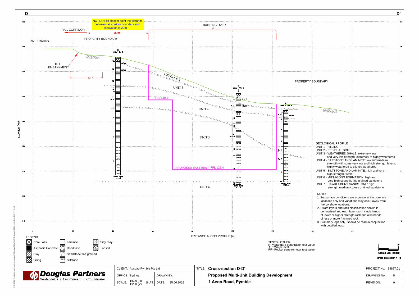
OFFICE: DRAWN BY:
CLIENT: TITLE: PROJECT No:
DRAWING No:
REVISION:25.06.2015
5
Core Loss
Asphaltic Concrete
Clay
1:500 (H)
1:200 (V)
SCALE: @ A3
Sydney
DATE:
TESTS / OTHER
LEGEND
DISTANCE ALONG PROFILE (m)
Filling
Laminite
Roadbase
Sandstone fine grained
Siltstone
Silty Clay
Topsoil
Proposed Multi-Unit Building Development
D D'
1 Avon Road, Pymble
Ausbao Pymble Pty Ltd
Cross-section D-D'
84887.01
N Standard penetration test value
Water level
PP Pocket penetrometer test value
UNITS 1 & 2
UNIT 3
UNIT 4
UNIT 5
UNIT 6
FFL 125.4 PROPOSED BASEMENT
PROPERTY BOUNDARY
GEOLOGICAL PROFILE
UNIT 1 - FILLING
UNIT 2 - RESIDUAL SOILS
UNIT 3 - WEATHERED SHALE: extremely low
and very low strength, extremely to highly weathered
UNIT 4 - SILTSTONE AND LAMINITE: low and medium
strength with some very low and high strength layers,
UNIT 5 - SILTSTONE AND LAMINITE: high and very
high strength, fresh
UNIT 6 - MITTAGONG FORMATION: high and
very high strength, fine grained sandstone
UNIT 7 - HAWKESBURY SANDSTONE: high
strength medium coarse grained sandstone
NOTE:
1. Subsurface conditions are accurate at the borehole
locations only and variations may occur away from
the borehole locations.
2. Strata layers and rock classification shown is
generalised and each layer can include bands
of lower or higher strength rock and also bands
of less or more fractured rock.
3. Summary logs only. Should be read in conjunction
with detailed logs.
highly weathered to slightly weathered
0
PROPERTY BOUNDARY
RAIL TRACKS
FFL 139.2
FILL
EMBANKMENT
30m
RAIL CORRIDOR
NOTE: At its closest point the distance
between rail corridor boundary and
excavation is 22m
BUILDING OVER
30m30m
P:\8
48
87
.0
1 - A
vo
n R
d P
ym
ble
G
eo
te
ch
In
ve
stig
atio
n\7
.0
D
ra
win
gs\7
.2
O
ut\8
48
87
.0
1-5
.d
wg
, 1
/0
7/2
01
5 1
1:2
8:0
2 A
M, D
WG
T
o P
DF
.p
c3

Appendix C
Results of Field Work

July 2010
Rock Strength Rock strength is defined by the Point Load Strength Index (Is(50)) and refers to the strength of the rock substance and not the strength of the overall rock mass, which may be considerably weaker due to defects. The test procedure is described by Australian Standard 4133.4.1 - 1993. The terms used to describe rock strength are as follows:
Term Abbreviation Point Load Index Is(50) MPa
Approx Unconfined Compressive Strength MPa*
Extremely low EL <0.03 <0.6
Very low VL 0.03 - 0.1 0.6 - 2
Low L 0.1 - 0.3 2 - 6
Medium M 0.3 - 1.0 6 - 20
High H 1 - 3 20 - 60
Very high VH 3 - 10 60 - 200
Extremely high EH >10 >200 * Assumes a ratio of 20:1 for UCS to Is(50)
Degree of Weathering The degree of weathering of rock is classified as follows:
Term Abbreviation Description Extremely weathered EW Rock substance has soil properties, i.e. it can be remoulded
and classified as a soil but the texture of the original rock is still evident.
Highly weathered HW Limonite staining or bleaching affects whole of rock substance and other signs of decomposition are evident. Porosity and strength may be altered as a result of iron leaching or deposition. Colour and strength of original fresh rock is not recognisable
Moderately weathered
MW Staining and discolouration of rock substance has taken place
Slightly weathered SW Rock substance is slightly discoloured but shows little or no change of strength from fresh rock
Fresh stained Fs Rock substance unaffected by weathering but staining visible along defects
Fresh Fr No signs of decomposition or staining Degree of Fracturing The following classification applies to the spacing of natural fractures in diamond drill cores. It includes bedding plane partings, joints and other defects, but excludes drilling breaks.
Term Description Fragmented Fragments of <20 mm Highly Fractured Core lengths of 20-40 mm with some fragments Fractured Core lengths of 40-200 mm with some shorter and longer sections Slightly Fractured Core lengths of 200-1000 mm with some shorter and loner sections Unbroken Core lengths mostly > 1000 mm

July 2010
Rock Quality Designation The quality of the cored rock can be measured using the Rock Quality Designation (RQD) index, defined as:
RQD % = cumulative length of 'sound' core sections ≥ 100 mm long total drilled length of section being assessed
where 'sound' rock is assessed to be rock of low strength or better. The RQD applies only to natural fractures. If the core is broken by drilling or handling (i.e. drilling breaks) then the broken pieces are fitted back together and are not included in the calculation of RQD. Stratification Spacing For sedimentary rocks the following terms may be used to describe the spacing of bedding partings:
Term Separation of Stratification Planes Thinly laminated < 6 mm Laminated 6 mm to 20 mm Very thinly bedded 20 mm to 60 mm Thinly bedded 60 mm to 0.2 m Medium bedded 0.2 m to 0.6 m Thickly bedded 0.6 m to 2 m Very thickly bedded > 2 m

July 2010
Sampling Sampling is carried out during drilling or test pitting to allow engineering examination (and laboratory testing where required) of the soil or rock. Disturbed samples taken during drilling provide information on colour, type, inclusions and, depending upon the degree of disturbance, some information on strength and structure. Undisturbed samples are taken by pushing a thin-walled sample tube into the soil and withdrawing it to obtain a sample of the soil in a relatively undisturbed state. Such samples yield information on structure and strength, and are necessary for laboratory determination of shear strength and compressibility. Undisturbed sampling is generally effective only in cohesive soils. Test Pits Test pits are usually excavated with a backhoe or an excavator, allowing close examination of the in-situ soil if it is safe to enter into the pit. The depth of excavation is limited to about 3 m for a backhoe and up to 6 m for a large excavator. A potential disadvantage of this investigation method is the larger area of disturbance to the site. Large Diameter Augers Boreholes can be drilled using a rotating plate or short spiral auger, generally 300 mm or larger in diameter commonly mounted on a standard piling rig. The cuttings are returned to the surface at intervals (generally not more than 0.5 m) and are disturbed but usually unchanged in moisture content. Identification of soil strata is generally much more reliable than with continuous spiral flight augers, and is usually supplemented by occasional undisturbed tube samples. Continuous Spiral Flight Augers The borehole is advanced using 90-115 mm diameter continuous spiral flight augers which are withdrawn at intervals to allow sampling or in-situ testing. This is a relatively economical means of drilling in clays and sands above the water table. Samples are returned to the surface, or may be collected after withdrawal of the auger flights, but they are disturbed and may be mixed with soils from the sides of the hole. Information from the drilling (as distinct from specific sampling by SPTs or undisturbed samples) is of relatively low
reliability, due to the remoulding, possible mixing or softening of samples by groundwater. Non-core Rotary Drilling The borehole is advanced using a rotary bit, with water or drilling mud being pumped down the drill rods and returned up the annulus, carrying the drill cuttings. Only major changes in stratification can be determined from the cuttings, together with some information from the rate of penetration. Where drilling mud is used this can mask the cuttings and reliable identification is only possible from separate sampling such as SPTs. Continuous Core Drilling A continuous core sample can be obtained using a diamond tipped core barrel, usually with a 50 mm internal diameter. Provided full core recovery is achieved (which is not always possible in weak rocks and granular soils), this technique provides a very reliable method of investigation. Standard Penetration Tests Standard penetration tests (SPT) are used as a means of estimating the density or strength of soils and also of obtaining a relatively undisturbed sample. The test procedure is described in Australian Standard 1289, Methods of Testing Soils for Engineering Purposes - Test 6.3.1. The test is carried out in a borehole by driving a 50 mm diameter split sample tube under the impact of a 63 kg hammer with a free fall of 760 mm. It is normal for the tube to be driven in three successive 150 mm increments and the 'N' value is taken as the number of blows for the last 300 mm. In dense sands, very hard clays or weak rock, the full 450 mm penetration may not be practicable and the test is discontinued. The test results are reported in the following form. • In the case where full penetration is obtained
with successive blow counts for each 150 mm of, say, 4, 6 and 7 as:
4,6,7 N=13
• In the case where the test is discontinued before the full penetration depth, say after 15 blows for the first 150 mm and 30 blows for the next 40 mm as:
15, 30/40 mm

July 2010
The results of the SPT tests can be related empirically to the engineering properties of the soils. Dynamic Cone Penetrometer Tests / Perth Sand Penetrometer Tests Dynamic penetrometer tests (DCP or PSP) are carried out by driving a steel rod into the ground using a standard weight of hammer falling a specified distance. As the rod penetrates the soil the number of blows required to penetrate each successive 150 mm depth are recorded. Normally there is a depth limitation of 1.2 m, but this may be extended in certain conditions by the use of extension rods. Two types of penetrometer are commonly used. • Perth sand penetrometer - a 16 mm diameter
flat ended rod is driven using a 9 kg hammer dropping 600 mm (AS 1289, Test 6.3.3). This test was developed for testing the density of sands and is mainly used in granular soils and filling.
• Cone penetrometer - a 16 mm diameter rod with a 20 mm diameter cone end is driven using a 9 kg hammer dropping 510 mm (AS 1289, Test 6.3.2). This test was developed initially for pavement subgrade investigations, and correlations of the test results with California Bearing Ratio have been published by various road authorities.

July 2010
Description and Classification Methods The methods of description and classification of soils and rocks used in this report are based on Australian Standard AS 1726, Geotechnical Site Investigations Code. In general, the descriptions include strength or density, colour, structure, soil or rock type and inclusions. Soil Types Soil types are described according to the predominant particle size, qualified by the grading of other particles present:
Type Particle size (mm) Boulder >200 Cobble 63 - 200 Gravel 2.36 - 63 Sand 0.075 - 2.36 Silt 0.002 - 0.075 Clay <0.002
The sand and gravel sizes can be further subdivided as follows:
Type Particle size (mm) Coarse gravel 20 - 63 Medium gravel 6 - 20 Fine gravel 2.36 - 6 Coarse sand 0.6 - 2.36 Medium sand 0.2 - 0.6 Fine sand 0.075 - 0.2
The proportions of secondary constituents of soils are described as:
Term Proportion Example And Specify Clay (60%) and
Sand (40%) Adjective 20 - 35% Sandy Clay Slightly 12 - 20% Slightly Sandy
Clay With some 5 - 12% Clay with some
sand With a trace of 0 - 5% Clay with a trace
of sand
Definitions of grading terms used are: • Well graded - a good representation of all
particle sizes • Poorly graded - an excess or deficiency of
particular sizes within the specified range • Uniformly graded - an excess of a particular
particle size • Gap graded - a deficiency of a particular
particle size with the range Cohesive Soils Cohesive soils, such as clays, are classified on the basis of undrained shear strength. The strength may be measured by laboratory testing, or estimated by field tests or engineering examination. The strength terms are defined as follows:
Description Abbreviation Undrained shear strength
(kPa) Very soft vs <12 Soft s 12 - 25 Firm f 25 - 50 Stiff st 50 - 100 Very stiff vst 100 - 200 Hard h >200
Cohesionless Soils Cohesionless soils, such as clean sands, are classified on the basis of relative density, generally from the results of standard penetration tests (SPT), cone penetration tests (CPT) or dynamic penetrometers (PSP). The relative density terms are given below:
Relative Density
Abbreviation SPT N value
CPT qc value (MPa)
Very loose vl <4 <2 Loose l 4 - 10 2 -5 Medium dense
md 10 - 30 5 - 15
Dense d 30 - 50 15 - 25 Very dense
vd >50 >25

July 2010
Soil Origin It is often difficult to accurately determine the origin of a soil. Soils can generally be classified as: • Residual soil - derived from in-situ weathering
of the underlying rock; • Transported soils - formed somewhere else
and transported by nature to the site; or • Filling - moved by man. Transported soils may be further subdivided into: • Alluvium - river deposits • Lacustrine - lake deposits • Aeolian - wind deposits • Littoral - beach deposits • Estuarine - tidal river deposits • Talus - scree or coarse colluvium • Slopewash or Colluvium - transported
downslope by gravity assisted by water. Often includes angular rock fragments and boulders.

July 2010
Introduction These notes summarise abbreviations commonly used on borehole logs and test pit reports. Drilling or Excavation Methods C Core Drilling R Rotary drilling SFA Spiral flight augers NMLC Diamond core - 52 mm dia NQ Diamond core - 47 mm dia HQ Diamond core - 63 mm dia PQ Diamond core - 81 mm dia Water
Water seep Water level
Sampling and Testing A Auger sample B Bulk sample D Disturbed sample E Environmental sample U50 Undisturbed tube sample (50mm) W Water sample pp pocket penetrometer (kPa) PID Photo ionisation detector PL Point load strength Is(50) MPa S Standard Penetration Test V Shear vane (kPa) Description of Defects in Rock The abbreviated descriptions of the defects should be in the following order: Depth, Type, Orientation, Coating, Shape, Roughness and Other. Drilling and handling breaks are not usually included on the logs. Defect Type B Bedding plane Cs Clay seam Cv Cleavage Cz Crushed zone Ds Decomposed seam F Fault J Joint Lam lamination Pt Parting Sz Sheared Zone V Vein
Orientation The inclination of defects is always measured from the perpendicular to the core axis. h horizontal v vertical sh sub-horizontal sv sub-vertical Coating or Infilling Term cln clean co coating he healed inf infilled stn stained ti tight vn veneer Coating Descriptor ca calcite cbs carbonaceous cly clay fe iron oxide mn manganese slt silty Shape cu curved ir irregular pl planar st stepped un undulating Roughness po polished ro rough sl slickensided sm smooth vr very rough Other fg fragmented bnd band qtz quartz
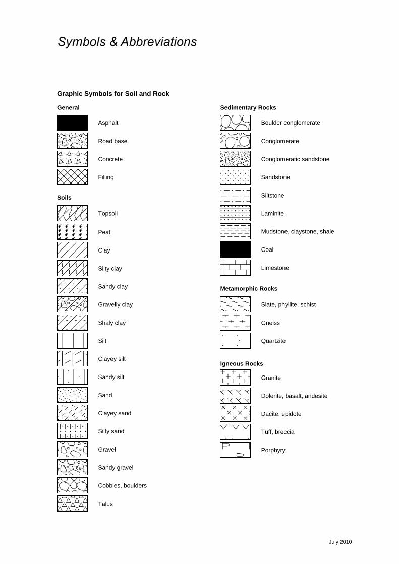
July 2010
Graphic Symbols for Soil and Rock General
Soils
Sedimentary Rocks
Metamorphic Rocks
Igneous Rocks
Road base
Filling
Concrete
Asphalt
Topsoil
Peat
Clay
Conglomeratic sandstone
Conglomerate
Boulder conglomerate
Sandstone
Slate, phyllite, schist
Siltstone
Mudstone, claystone, shale
Coal
Limestone
Porphyry
Cobbles, boulders
Sandy gravel
Laminite
Silty sand
Clayey sand
Silty clay
Sandy clay
Gravelly clay
Shaly clay
Silt
Clayey silt
Sandy silt
Sand
Gravel
Talus
Gneiss
Quartzite
Dolerite, basalt, andesite
Granite
Tuff, breccia
Dacite, epidote
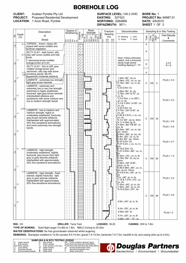
Note: Unless otherwisestated, rock is fracturedalong rough planarbedding dipping 0°- 10°
1.94m: B0°, cly co2.08m: J70°, un, ro, cly2.18m: J60°, un, ro, fe,cly2.23-2.6m: Cs
2.68m: B0°, fe, cly2.78m: J40° & 75°, st,ro, fe3.0-3.25m: J, sv (90°),pl, ro, cly3.3 & 3.35m: J's 65°, un,ro, cly3.45-3.6m: Cs3.75m: J20° & 45°, st,ro, cly3.82 & 3.91m: J, sv, un,ro, cly4.1m: B0°, cly co, 5mm4.11-4.35m: fg, fe4.48m: J60° P& 90°, st,ro, fe4.54m: J80°, un, ro, clyinf, 10mm4.65m: J60°, pl, sm, cln4.8m: J50°, un, ro, fe4.9m: B0°, cly, 10mm4.97-5.0m: Cs5.07-5.2m: J, sv, cu, ro,cly5.18-5.23m: Cs5.27-5.42m: J80°, un, ro,fe5.42m: J70°, un, ro, fe5.78m: B0°, fe, cly co,5mm5.82m: J35° & 80°,st/un, ro, fe5.86-5.96m: J65°, un, ro,fe, cly inf, 10mm6.2 & 6.4m: J30°, pl, ro,fe7m: J45°, pl, ro, fe7.18 & 7.27m: J70°, un,ro, cln7.42m: J45°, pl, ro, cln7.84m: J40°, pl, ro, cln8.15-8.25m: J70°, he
8.9m: J45°, pl, ro, fe
9.3m: J30°, pl, ro, fe
9.48m: B0°, fe
9.7m: J30°, pl, ro, fe
9.88m: J30° - 70°, cu,
TOPSOIL - brown, clayey silttopsoil with some rootlets andsurficial vegetation
SILTY CLAY - dark brown, siltyclay with some rootlets and treeroots,
- becoming brown mottledorange-brown at 0.3m
SILTY CLAY - firm to stiff, greymottled orange-brown andred-brown, silty clay with someironstone gravel, Mc<PL.Apparently moderate plasticity
LAMINITE - extremely low strength,light grey-brown laminite
LAMINITE - extremely andextremely low to very low strength,extremely to highly weathered,fractured, light grey-brown laminite(interbedded siltstone andsandstone) with some medium andlow to medium strength bands
LAMINITE - low to medium andmedium strength, highly tomoderately weathered, fractured,grey-brown laminite (siltstoneinterbedded with approximately25% fine sandstone laminations)and some extremely low strengthbands
LAMINITE - high strength,moderately weathered, slightlyfractured, grey-brown then lightgrey to grey laminite (siltstoneinterbedded with approximately20% fine sandstone laminations)
LAMINITE - high strength, freshstained, slightly fractured, lightgrey to grey laminite (siltstoneinterbedded with approximately20% fine sandstone laminations)
2,3,5N = 8
PL(A) = 0.4
PL(A) = 0.3
PL(A) = 0.9
PL(A) = 0.9
PL(A) = 0.7
PL(A) = 1.4
PL(A) = 3.4
PL(A) = 2.8
PL(A) = 2
0
35
80
90
100
100
100
100
A
A
S
A
C
C
C
C
0.1
0.7
1.71.8
3.75
6.0
7.3
FractureSpacing(m)
0.01
Depth(m) B - Bedding
S - Shear
RockStrength
Type
Sampling & In Situ Testing
Ex Low
Very Low
Low
Medium
High
Very High
Ex High
0.10
0.50
1.00 RQD%
Core
Rec. %
Graphic
Log
Water
Degree ofWeathering
EW
HW
MW
SW
FS
FR
Description
of
Strata
1
2
3
4
5
6
7
8
9
J - Joint
F - Fault
RL
140
139
138
137
136
135
134
133
132
131
Test Results&
Comments0.05
Discontinuities
BOREHOLE LOG BOREHOLE LOG BOREHOLE LOG BOREHOLE LOG BOREHOLE LOG BOREHOLE LOG BOREHOLE LOG
CLIENT:
PROJECT:
LOCATION: 1 Avon Road, Pymble
SAMPLING & IN SITU TESTING LEGENDA Auger sample G Gas sample PID Photo ionisation detector (ppm)B Bulk sample P Piston sample PL(A) Point load axial test Is(50) (MPa)BLK Block sample Ux Tube sample (x mm dia.) PL(D) Point load diametral test Is(50) (MPa)C Core drilling W Water sample pp Pocket penetrometer (kPa)D Disturbed sample Water seep S Standard penetration testE Environmental sample Water level V Shear vane (kPa)
BORE No: 1
PROJECT No: 84887.01
DATE: 4/6/2015
SHEET 1 OF 3
DRILLER: Terra Test LOGGED: SI/JS CASING: HW to 1.8m
Ausbao Pymble Pty Ltd
Proposed Residential Development
REMARKS:
RIG: XC
WATER OBSERVATIONS:
TYPE OF BORING:
No free groundwater observed whilst augering
Solid flight auger (Tc-Bit) to 1.8m; NMLC-Coring to 25.32m
Standpipe installed to 14.5m (screen 8.5-14.5m; gravel 7.5-14.5m; bentonite 7.0-7.5m; backfill to GL and casing sitck-up to 0.5m)
SURFACE LEVEL: 140.2 AHD
EASTING: 327423
NORTHING: 6264869
DIP/AZIMUTH: 90°/--

ro, fe10.12m: J30° & 70°, st,ro, fe10.33m: J35°, pl, ro, cln10.42m: J45°, pl, ro, cln10.61m: J60°, pl, ro, cln
11.15m: J45°, pl, ro, cln
11.66m: J30°, pl, ro, cln
13.22m: J30°, pl, ro, cln13.22-13.9m: J (x3) 30°-45°, pl, sm, cln
14.52 & 14.75m: J (x3)45°, pl, sm, cln
14.93m: J70°, he
15.16m: J45°, sl, sm, si15.2-15.3m: Sz15.3m: J60°, st, ro, cln15.5-15.7m: J65° & 90°,st, sm, cln
16.03m: J60°, pl, sm, cln16.12m: J60°- 70°, cu,sm, cln
16.54m: J45°, sm, pl, cln
16.73m: J35°, pl, ro, cly16.85m: J30°, pl, sm, cln
17.08m: J55°, sl, sm, cln
17.55m: J30°, pl, ro, cly
18.73m: B0°, cly
SILTSTONE - high strength, fresh,slightly fractured and unbroken,grey siltstone interbedded withapproximately 5-10% finesandstone laminations
SANDSTONE - very high strength,fresh, unbroken, light grey, finegrained sandstone
PL(A) = 2.1
PL(A) = 2.1
PL(A) = 2.6
PL(A) = 2.2
PL(A) = 1.6
PL(A) = 2.2
PL(A) = 1.4
PL(A) = 2.1
PL(A) = 3.2
PL(A) = 3.9
90
95
100
96
100
100
100
100
100
100
C
C
C
C
C
10.15
17.5
FractureSpacing(m)
0.01
Depth(m) B - Bedding
S - Shear
RockStrength
Type
Sampling & In Situ Testing
Ex Low
Very Low
Low
Medium
High
Very High
Ex High
0.10
0.50
1.00 RQD%
Core
Rec. %
Graphic
Log
Water
Degree ofWeathering
EW
HW
MW
SW
FS
FR
Description
of
Strata
11
12
13
14
15
16
17
18
19
J - Joint
F - Fault
RL
130
129
128
127
126
125
124
123
122
121
Test Results&
Comments0.05
Discontinuities
BOREHOLE LOG BOREHOLE LOG BOREHOLE LOG BOREHOLE LOG BOREHOLE LOG BOREHOLE LOG BOREHOLE LOG
CLIENT:
PROJECT:
LOCATION: 1 Avon Road, Pymble
SAMPLING & IN SITU TESTING LEGENDA Auger sample G Gas sample PID Photo ionisation detector (ppm)B Bulk sample P Piston sample PL(A) Point load axial test Is(50) (MPa)BLK Block sample Ux Tube sample (x mm dia.) PL(D) Point load diametral test Is(50) (MPa)C Core drilling W Water sample pp Pocket penetrometer (kPa)D Disturbed sample Water seep S Standard penetration testE Environmental sample Water level V Shear vane (kPa)
BORE No: 1
PROJECT No: 84887.01
DATE: 4/6/2015
SHEET 2 OF 3
DRILLER: Terra Test LOGGED: SI/JS CASING: HW to 1.8m
Ausbao Pymble Pty Ltd
Proposed Residential Development
REMARKS:
RIG: XC
WATER OBSERVATIONS:
TYPE OF BORING:
No free groundwater observed whilst augering
Solid flight auger (Tc-Bit) to 1.8m; NMLC-Coring to 25.32m
Standpipe installed to 14.5m (screen 8.5-14.5m; gravel 7.5-14.5m; bentonite 7.0-7.5m; backfill to GL and casing sitck-up to 0.5m)
SURFACE LEVEL: 140.2 AHD
EASTING: 327423
NORTHING: 6264869
DIP/AZIMUTH: 90°/--
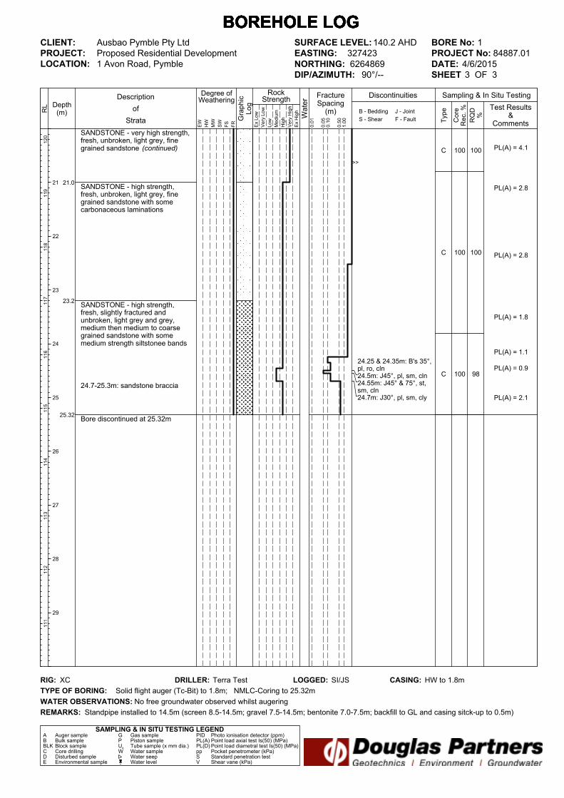
>>
24.25 & 24.35m: B's 35°,pl, ro, cln24.5m: J45°, pl, sm, cln24.55m: J45° & 75°, st,sm, cln24.7m: J30°, pl, sm, cly
SANDSTONE - very high strength,fresh, unbroken, light grey, finegrained sandstone (continued)
SANDSTONE - high strength,fresh, unbroken, light grey, finegrained sandstone with somecarbonaceous laminations
SANDSTONE - high strength,fresh, slightly fractured andunbroken, light grey and grey,medium then medium to coarsegrained sandstone with somemedium strength siltstonee bands
24.7-25.3m: sandstone braccia
Bore discontinued at 25.32m
PL(A) = 4.1
PL(A) = 2.8
PL(A) = 2.8
PL(A) = 1.8
PL(A) = 1.1
PL(A) = 0.9
PL(A) = 2.1
100
100
98
100
100
100
C
C
C
21.0
23.2
25.32
FractureSpacing(m)
0.01
Depth(m) B - Bedding
S - Shear
RockStrength
Type
Sampling & In Situ Testing
Ex Low
Very Low
Low
Medium
High
Very High
Ex High
0.10
0.50
1.00 RQD%
Core
Rec. %
Graphic
Log
Water
Degree ofWeathering
EW
HW
MW
SW
FS
FR
Description
of
Strata
21
22
23
24
25
26
27
28
29
J - Joint
F - Fault
RL
120
119
118
117
116
115
114
113
112
111
Test Results&
Comments0.05
Discontinuities
BOREHOLE LOG BOREHOLE LOG BOREHOLE LOG BOREHOLE LOG BOREHOLE LOG BOREHOLE LOG BOREHOLE LOG
CLIENT:
PROJECT:
LOCATION: 1 Avon Road, Pymble
SAMPLING & IN SITU TESTING LEGENDA Auger sample G Gas sample PID Photo ionisation detector (ppm)B Bulk sample P Piston sample PL(A) Point load axial test Is(50) (MPa)BLK Block sample Ux Tube sample (x mm dia.) PL(D) Point load diametral test Is(50) (MPa)C Core drilling W Water sample pp Pocket penetrometer (kPa)D Disturbed sample Water seep S Standard penetration testE Environmental sample Water level V Shear vane (kPa)
BORE No: 1
PROJECT No: 84887.01
DATE: 4/6/2015
SHEET 3 OF 3
DRILLER: Terra Test LOGGED: SI/JS CASING: HW to 1.8m
Ausbao Pymble Pty Ltd
Proposed Residential Development
REMARKS:
RIG: XC
WATER OBSERVATIONS:
TYPE OF BORING:
No free groundwater observed whilst augering
Solid flight auger (Tc-Bit) to 1.8m; NMLC-Coring to 25.32m
Standpipe installed to 14.5m (screen 8.5-14.5m; gravel 7.5-14.5m; bentonite 7.0-7.5m; backfill to GL and casing sitck-up to 0.5m)
SURFACE LEVEL: 140.2 AHD
EASTING: 327423
NORTHING: 6264869
DIP/AZIMUTH: 90°/--
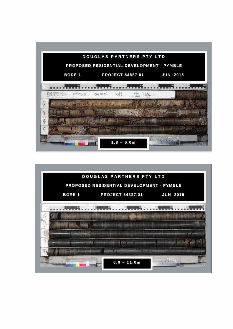
D O U G L A S P A R T N E R S P T Y L T D
PROPOSED RESIDENTIAL DEVELOPMENT - PYMBLE
BORE 1 PROJECT 84887.01 JUN 2015
1 . 8 – 6 . 0 m
D O U G L A S P A R T N E R S P T Y L T D
PROPOSED RESIDENTIAL DEVELOPMENT - PYMBLE
BORE 1 PROJECT 84887.01 JUN 2015
6 . 0 – 1 1 . 0 m

D O U G L A S P A R T N E R S P T Y L T D
PROPOSED RESIDENTIAL DEVELOPMENT - PYMBLE
BORE 1 PROJECT 84887.01 JUN 2015
1 1 . 0 – 1 6 . 0 m
D O U G L A S P A R T N E R S P T Y L T D
PROPOSED RESIDENTIAL DEVELOPMENT - PYMBLE
BORE 1 PROJECT 84887.01 JUN 2015
1 6 . 0 – 2 1 . 0 m

D O U G L A S P A R T N E R S P T Y L T D
PROPOSED RESIDENTIAL DEVELOPMENT - PYMBLE
BORE 1 PROJECT 84887.01 JUN 2015
21.0 – 25.32m

Note: Unless otherwisestated, rock is fracturedalong rough planarbedding dipping 0°- 10°
4.0-4.08m: Cz
4.3m: Fr, 0°, sm, pl, clyvn4.36m: Fr, 5°, sm, ir, cln4.38-4.42m: Cz
5.11m: B5°, sm, pl, clyvn5.14m: B5°, sm, pl, clyvn5.27m: B0°, sm, pl, cln5.28m: B0°, sm, pl, cln5.3m: B0°, sm, pl, cln5.32m: B0°, sm, pl, cln5.35m: B0°, sm, pl, cln5.43m: B0°, ro, pl, cln5.45m: B0°, ro, un, cln5.52m: J0°, ro, un, cln5.6m: J5°, ro, un, cln5.63m: J0°, ro, un, cln5.7-5.77m: Cz5.98m: J0°, ro, pl, cln6.05m: J0°, ro, pl, cln6.2m: B5°, ro, un, cln6.28m: B0°, sm, pl, clyvn6.42m: J5°, ro, un, cln6.45-6.47m: Cz
TOPSOIL - brown, clayey silttopsoil with some rootlets andsurficial vegetation
SILTY CLAY - apparently stiff, darkgrey, silty clay with trace roots,humid
SILTY CLAY - firm, orange-brown,silty clay, damp
SILTY CLAY - stiff, grey mottledred and orange, silty clay, damp
- with ironstone gravel from 2.4m
SILTSTONE - very low then lowstrength, extremely weathered,fragmented then highly fractured,grey siltstone
- sandstone bed from 5.11m to5.14m
SANDSTONE - medium then highstrength, slightly weathered thenfresh, fractured then slightlyfractured, grey sandstone withorange-brown and red-brownlaminations from 5.36m to 5.64m
- interbedded shale from 5.71m to5.97m and from 6.45m to 6.47m
Bore discontinued at 6.71m
3,2,4N = 6
4,6,6N = 12
PL(A) = 0.16PL(A) = 0.09
PL(A) = 0.15
PL(A) = 0.92
PL(A) = 1.9
PL(A) = 2.5
80
45
75
100
100
100
AA
A
A
S
S
C
C
C
0.10.2
0.8
3.7
5.36
6.71
FractureSpacing(m)
0.01
Depth(m) B - Bedding
S - Shear
RockStrength
Type
Sampling & In Situ Testing
Ex Low
Very Low
Low
Medium
High
Very High
Ex High
0.10
0.50
1.00 RQD%
Core
Rec. %
Graphic
Log
Water
Degree ofWeathering
EW
HW
MW
SW
FS
FR
Description
of
Strata
1
2
3
4
5
6
7
8
9
J - Joint
F - Fault
RL
127
126
125
124
123
122
121
120
119
118
Test Results&
Comments0.05
Discontinuities
BOREHOLE LOG BOREHOLE LOG BOREHOLE LOG BOREHOLE LOG BOREHOLE LOG BOREHOLE LOG BOREHOLE LOG
CLIENT:
PROJECT:
LOCATION: 1 Avon Road, Pymble
SAMPLING & IN SITU TESTING LEGENDA Auger sample G Gas sample PID Photo ionisation detector (ppm)B Bulk sample P Piston sample PL(A) Point load axial test Is(50) (MPa)BLK Block sample Ux Tube sample (x mm dia.) PL(D) Point load diametral test Is(50) (MPa)C Core drilling W Water sample pp Pocket penetrometer (kPa)D Disturbed sample Water seep S Standard penetration testE Environmental sample Water level V Shear vane (kPa)
BORE No: 2
PROJECT No: 84887.01
DATE: 1/6/2015
SHEET 1 OF 1
DRILLER: Terratest LOGGED: CG CASING: to 4.0m
Ausbao Pymble Pty Ltd
Proposed Residential Development
REMARKS:
RIG: Drillcat
WATER OBSERVATIONS:
TYPE OF BORING:
No free groundwater observed whilst augering
Solid flight auger to 4.0m; HQ-Coring to 6.71m
SURFACE LEVEL: 127.3 AHD
EASTING: 327371
NORTHING: 6264796
DIP/AZIMUTH: 90°/--

D O U G L A S P A R T N E R S P T Y L T D
PROPOSED RESIDENTIAL DEVELOPMENT - PYMBLE
BORE 2 PROJECT 84887.01 JUN 2015
4.0 – 6 .71m
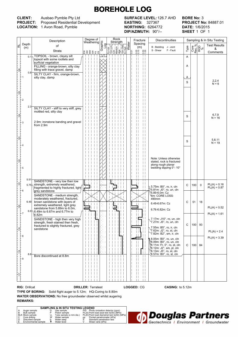
Note: Unless otherwisestated, rock is fracturedalong rough planarbedding dipping 0°- 10°
5.75m: B0°, ro, ir, cln5.81m: J0°, ro, un, cln5.89-6.0m: Cz6m: CORE LOSS:490mm
6.49-6.67m: Cz
6.76-6.82m: Cz
7.17m: J10°, ro, un, cln7.27m: J5°, ro, un, cln
7.55m: B5°, ro, ir, cln7.62m: J2°, ro, st, cln7.82m: B2°, sm, ir, cln
8.05m: B0°, ro, un, cln8.09m: B0°, ro, un, cln8.11m: Fr, 0°, ro, st, cln8.12m: J2°, sm, pl, cln8.13m: J5°, ro, st, cln8.57m: B0°, ro, st, cln
TOPSOIL - brown, clayey silttopsoil with some rootlets andsurficial vegetation
FILLING - orange-brown, silty clayfilling with trace gravel, damp
SILTY CLAY - firm, orange-brown,silty clay, damp
SILTY CLAY - stiff to very stiff, greymottled red, silty clay
2.9m: ironstone banding and gravelfrom 2.9m
SANDSTONE - very low then lowstrength, extremely weathered,fragmented to highly fractured, lightgrey sandstone
SANDSTONE - medium strength,moderately weathered, fractured,brown sandstone with layers ofextremely weathered, light greysandstone from 5.89m to 6.0m,6.49m to 6.67m and 6.77m to6.82m
SANDSTONE - high then very highstrength, fresh stained then fresh,fractured to slightly fractured, greysandstone
Bore discontinued at 8.8m
2,2,4N = 6
6,7,9N = 16
5,8,11N = 19
PL(A) = 0.16PL(A) = 0.87
PL(A) = 0.52
PL(A) = 1.61
PL(A) = 2.4
PL(A) = 3.39
0
18
93
84
100
51
100
100
A
A
A
S
S
S
C
C
C
C
0.1
0.8
2.3
5.51
5.75
6.49
6.9
8.8
FractureSpacing(m)
0.01
Depth(m) B - Bedding
S - Shear
RockStrength
Type
Sampling & In Situ Testing
Ex Low
Very Low
Low
Medium
High
Very High
Ex High
0.10
0.50
1.00 RQD%
Core
Rec. %
Graphic
Log
Water
Degree ofWeathering
EW
HW
MW
SW
FS
FR
Description
of
Strata
1
2
3
4
5
6
7
8
9
J - Joint
F - Fault
RL
126
125
124
123
122
121
120
119
118
117
Test Results&
Comments0.05
Discontinuities
BOREHOLE LOG BOREHOLE LOG BOREHOLE LOG BOREHOLE LOG BOREHOLE LOG BOREHOLE LOG BOREHOLE LOG
CLIENT:
PROJECT:
LOCATION: 1 Avon Road, Pymble
SAMPLING & IN SITU TESTING LEGENDA Auger sample G Gas sample PID Photo ionisation detector (ppm)B Bulk sample P Piston sample PL(A) Point load axial test Is(50) (MPa)BLK Block sample Ux Tube sample (x mm dia.) PL(D) Point load diametral test Is(50) (MPa)C Core drilling W Water sample pp Pocket penetrometer (kPa)D Disturbed sample Water seep S Standard penetration testE Environmental sample Water level V Shear vane (kPa)
BORE No: 3
PROJECT No: 84887.01
DATE: 1/6/2015
SHEET 1 OF 1
DRILLER: Terratest LOGGED: CG CASING: to 5.12m
Ausbao Pymble Pty Ltd
Proposed Residential Development
REMARKS:
RIG: Drillcat
WATER OBSERVATIONS:
TYPE OF BORING:
No free groundwater observed whilst augering
Solid flight auger to 5.12m; HQ-Coring to 8.80m
SURFACE LEVEL: 126.7 AHD
EASTING: 327367
NORTHING: 6264772
DIP/AZIMUTH: 90°/--
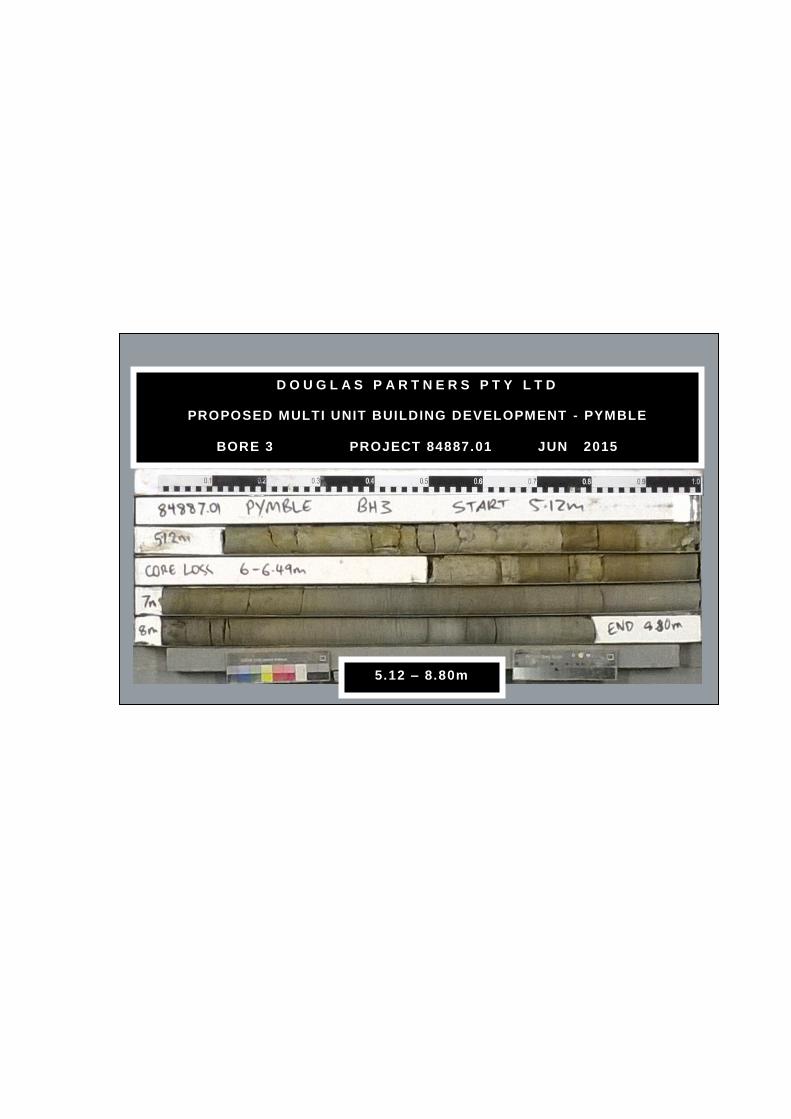
D O U G L A S P A R T N E R S P T Y L T D
PROPOSED MULTI UNIT BUILDING DEVELOPMENT - PYMBLE
BORE 3 PROJECT 84887.01 JUN 2015
5.12 – 8.80m

Note: Unless otherwisestated, rock is fracturedalong rough planarbedding dipping 0°- 10°
2.7m: CORE LOSS:60mm2.76m: J35°, un, ro, fe,cly3.1-3.17m: fg, fe
3.4m: J? 70°, un, ro, cly
3.95-4.75m: B's 5°, fe,cly vn
4.25m: J?, sv, un, ro, cly
4.9-5.7m: B's 0°- 5°, fe
5.8m: J60°, pl, sm, cly5.89m: B0°, fe6.02m: J60°, pl, ro, cly
6.48-6.62m: J,sv, ir, ro,fe, cly
6.8m: J60°, un, ro, fe6.92-7.31m: B's 0°, fe
7.31m: CORE LOSS:190mm
7.73m: J30°- 70°, cu, ro,cln8.0-8.4m: J's 50°- 70°,st, ro, fe
8.75m: J45°, pl, ro, fe
9m: J70°, pl, ro, fe9.1-9.55m: J (x7) 30°-35°, pl, ro, fe
9.6-9.63m: Cz9.85m: J35°, pl, ro, fe9.93m: J45°, un, ro, fe
TOPSOIL - brown, clayey silttopsoil with some rootlets andsurficial vegetation
FILLING - dark grey, silty sandyclay filling with a trace of roadbasegravel, moist
CLAY - stiff, brown clay, moist
LAMINITE - very low strength, lightgrey to grey laminite (interbeddedsiltstone and sandstone)
LAMINITE - medium strength,moderately then slightly weathered,fractured and slightly fractured,grey-brown laminite (siltstoneinterbedded with approximately25% fine sandstone laminations)
3.25-3.8m: very low strengthlaminite
3,4,5N = 9
30/130mmrefusal
PL(A) = 0.9
PL(A) = 0.8
PL(A) = 0.4
PL(A) = 0.9
PL(A) = 0.9
PL(A) = 0.4
PL(A) = 0.8
PL(A) = 0.6
100
30
20
100
100
93
A
A
A
S
S
C
C
C
0.05
0.8
2.0
2.72.76
7.31
7.5
9.5
FractureSpacing(m)
0.01
Depth(m) B - Bedding
S - Shear
RockStrength
Type
Sampling & In Situ Testing
Ex Low
Very Low
Low
Medium
High
Very High
Ex High
0.10
0.50
1.00 RQD%
Core
Rec. %
Graphic
Log
Water
Degree ofWeathering
EW
HW
MW
SW
FS
FR
Description
of
Strata
1
2
3
4
5
6
7
8
9
J - Joint
F - Fault
RL
136
135
134
133
132
131
130
129
128
127
Test Results&
Comments0.05
Discontinuities
BOREHOLE LOG BOREHOLE LOG BOREHOLE LOG BOREHOLE LOG BOREHOLE LOG BOREHOLE LOG BOREHOLE LOG
CLIENT:
PROJECT:
LOCATION: 1 Avon Road, Pymble
SAMPLING & IN SITU TESTING LEGENDA Auger sample G Gas sample PID Photo ionisation detector (ppm)B Bulk sample P Piston sample PL(A) Point load axial test Is(50) (MPa)BLK Block sample Ux Tube sample (x mm dia.) PL(D) Point load diametral test Is(50) (MPa)C Core drilling W Water sample pp Pocket penetrometer (kPa)D Disturbed sample Water seep S Standard penetration testE Environmental sample Water level V Shear vane (kPa)
BORE No: 4
PROJECT No: 84887.01
DATE: 3/6/2015
SHEET 1 OF 2
DRILLER: SY LOGGED: SI CASING: HW to 2.5m
Ausbao Pymble Pty Ltd
Proposed Residential Development
REMARKS:
RIG: Bobcat
WATER OBSERVATIONS:
TYPE OF BORING:
No free groundwater observed whilst augering
Solid flight auger to 2.5m; Rotary to 2.7m; NMLC-Coring to 12.5m
SURFACE LEVEL: 136.8 AHD
EASTING: 327415
NORTHING: 6264794
DIP/AZIMUTH: 90°/--
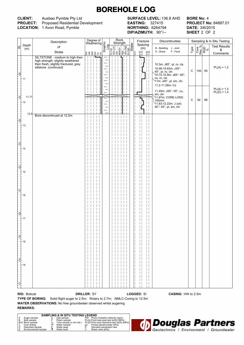
10.3m: J65°, pl, ro, cly
10.48-10.63m: J35°-45°, pl, ro, cln10.72-10.9m: J65°- 85°,cu, ro, cln11m: J45°, pl, sm, cln
11.2-11.28m: Cz
11.45m: J45°- 55°, cu,sm, cln11.67m: CORE LOSS:100mm11.83-12.22m: J (x4)40°- 45°, pl, sm, cln
SILTSTONE - medium to high thenhigh strength, slightly weatheredthen fresh, slightly fractured, greysiltstone (continued)
Bore discontinued at 12.5m
PL(A) = 1.2
PL(A) = 1.3PL(D) = 1.4
50
88
100
92
C
C11.77
12.5
FractureSpacing(m)
0.01
Depth(m) B - Bedding
S - Shear
RockStrength
Type
Sampling & In Situ Testing
Ex Low
Very Low
Low
Medium
High
Very High
Ex High
0.10
0.50
1.00 RQD%
Core
Rec. %
Graphic
Log
Water
Degree ofWeathering
EW
HW
MW
SW
FS
FR
Description
of
Strata
11
12
13
14
15
16
17
18
19
J - Joint
F - Fault
RL
126
125
124
123
122
121
120
119
118
117
Test Results&
Comments0.05
Discontinuities
BOREHOLE LOG BOREHOLE LOG BOREHOLE LOG BOREHOLE LOG BOREHOLE LOG BOREHOLE LOG BOREHOLE LOG
CLIENT:
PROJECT:
LOCATION: 1 Avon Road, Pymble
SAMPLING & IN SITU TESTING LEGENDA Auger sample G Gas sample PID Photo ionisation detector (ppm)B Bulk sample P Piston sample PL(A) Point load axial test Is(50) (MPa)BLK Block sample Ux Tube sample (x mm dia.) PL(D) Point load diametral test Is(50) (MPa)C Core drilling W Water sample pp Pocket penetrometer (kPa)D Disturbed sample Water seep S Standard penetration testE Environmental sample Water level V Shear vane (kPa)
BORE No: 4
PROJECT No: 84887.01
DATE: 3/6/2015
SHEET 2 OF 2
DRILLER: SY LOGGED: SI CASING: HW to 2.5m
Ausbao Pymble Pty Ltd
Proposed Residential Development
REMARKS:
RIG: Bobcat
WATER OBSERVATIONS:
TYPE OF BORING:
No free groundwater observed whilst augering
Solid flight auger to 2.5m; Rotary to 2.7m; NMLC-Coring to 12.5m
SURFACE LEVEL: 136.8 AHD
EASTING: 327415
NORTHING: 6264794
DIP/AZIMUTH: 90°/--
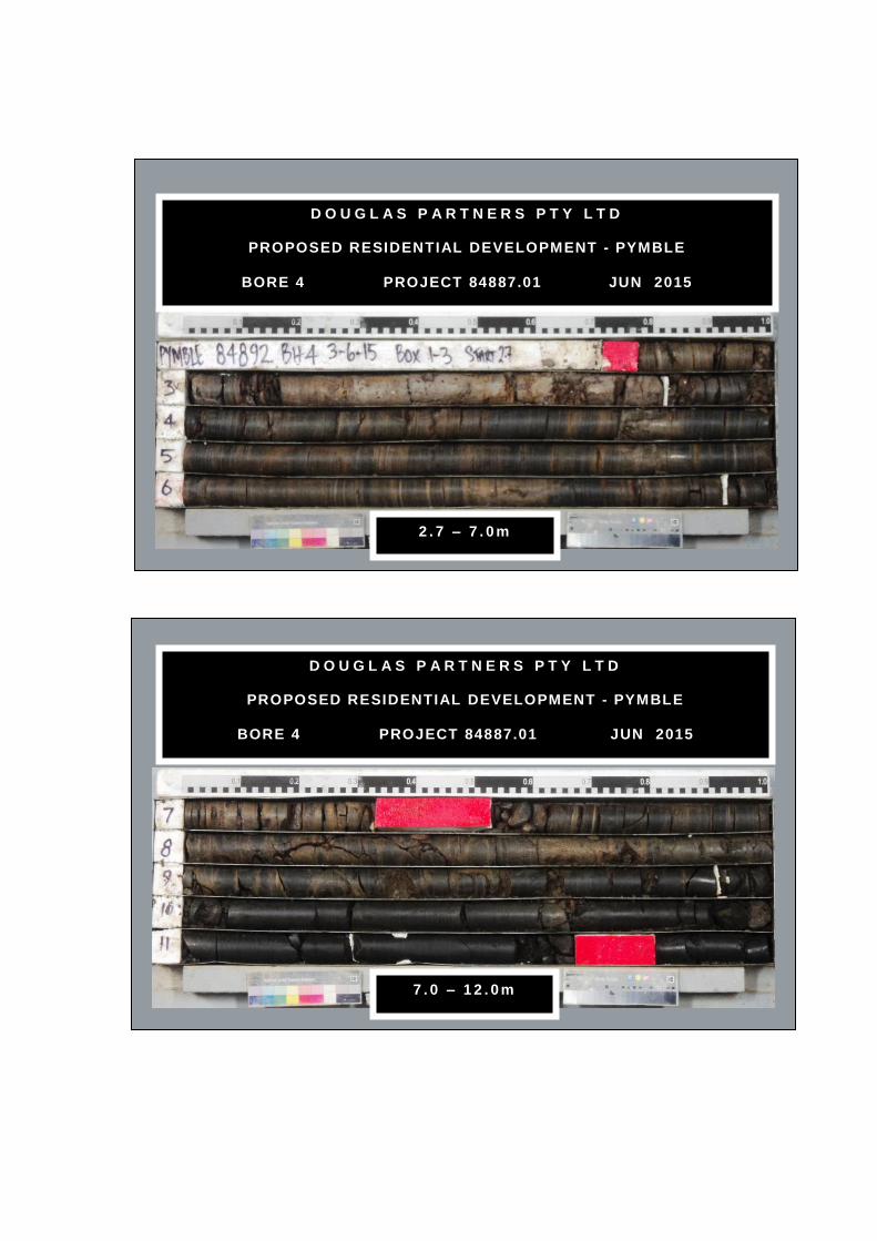
D O U G L A S P A R T N E R S P T Y L T D
PROPOSED RESIDENTIAL DEVELOPMENT - PYMBLE
BORE 4 PROJECT 84887.01 JUN 2015
2 . 7 – 7 . 0 m
D O U G L A S P A R T N E R S P T Y L T D
PROPOSED RESIDENTIAL DEVELOPMENT - PYMBLE
BORE 4 PROJECT 84887.01 JUN 2015
7 . 0 – 1 2 . 0 m
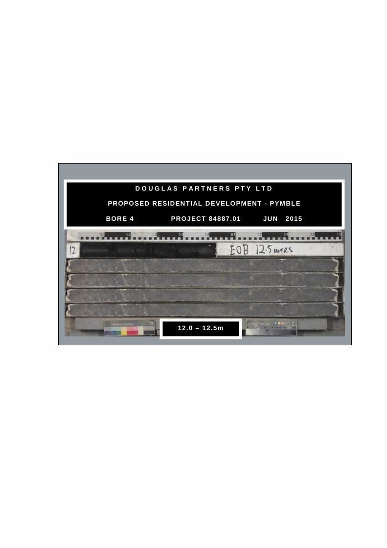
D O U G L A S P A R T N E R S P T Y L T D
PROPOSED RESIDENTIAL DEVELOPMENT - PYMBLE
BORE 4 PROJECT 84887.01 JUN 2015
12.0 – 12.5m

Note: Unless otherwisestated, rock is fracturedalong rough planarbedding dipping 0°- 10°
3.1m: CORE LOSS:200mm
3.8m: J70°, pl, ro, fe3.9m: J70°, pl, ro, fe
4.2m: J30°, pl, ro, fe4.32m: J50°, un, ro, cly4.43 & 4.51m: J's 55°,un, ro, fe, cly4.68m: J60°, un, ro, fe,cly4.76m: J70°, un, ro, cly4.84m: J70°, un, ro, fe5m: J, sv, un, ro, fe5.3m: CORE LOSS:300mm5.6-6.35m: Cs
6.55m: J70°, un, ro, fe,cly6.83, 7.2 & 7.6m B0°-5°, cly
7.72m: J30° & 50°, st,ro, fe7.85-7.87m: Cs8.05m: B0°, fe, cly
8.45m: J45°, pl, sm, cln
8.66-9.48m: B (x10) 0°,fe, cly co, 1-5mm
9.6m: J30°, pl, ro, cln9.63-9.93m: B (x4) 0°,cly co, 1-3mm
CONCRETE
CLAY - apparently stiff,orange-brown clay with someironstone gravel, moist
SHALY CLAY - very stiff, lightbrown, shaly clay, moist
LAMINITE - extremely low to verylow strength, grey-brown laminite(interbedded siltstone andsandstone)
LAMINITE - extremely low and verylow to low strength, extremely tohighly weathered, fragmented tofractured, grey-brown laminite withsome low and low to mediumstrength bands
LAMINITE - low to mediumstrength, slightly weathered,fractured and slightly fractured,grey-brown laminite (siltstoneinterbedded with approximately20% fine sandstone laminations)
LAMINITE - very low to lowstrength, highly weathered, slightlyfractured, grey-brown laminite
LAMINITE - medium and highstrength, slightly weathered, slightlyfractured, light grey-brown laminite(siltstone interbedded withapproximately 30% fine grainedsandstone laminations)
LAMINITE - high strength, fresh,slightly fractured, grey laminite(siltstone interbedded withapproximately 25% fine grainedsandstone laminations)
7,10,14N = 24
23,20/100mmrefusal
PL(A) = 0.2
PL(A) = 0.3
PL(A) = 0.3
PL(A) = 0.3
PL(A) = 0.5
PL(A) = 1.2
PL(A) = 1.3
0
0
60
64
91
85
100
100
A
A
A
S
S
C
C
C
C
0.1
0.8
1.3
3.1
3.3
5.6
6.35
7.0
7.85
8.85
10.0
FractureSpacing(m)
0.01
Depth(m) B - Bedding
S - Shear
RockStrength
Type
Sampling & In Situ Testing
Ex Low
Very Low
Low
Medium
High
Very High
Ex High
0.10
0.50
1.00 RQD
%
Core
Rec. %
Graphic
Log
Water
Degree ofWeathering
EW
HW
MW
SW
FS
FR
Description
of
Strata
1
2
3
4
5
6
7
8
9
J - Joint
F - Fault
RL
146
145
144
143
142
141
140
139
138
137
Test Results&
Comments0.05
Discontinuities
BOREHOLE LOG BOREHOLE LOG BOREHOLE LOG BOREHOLE LOG BOREHOLE LOG BOREHOLE LOG BOREHOLE LOG
CLIENT:
PROJECT:
LOCATION: 1 Avon Road, Pymble
SAMPLING & IN SITU TESTING LEGENDA Auger sample G Gas sample PID Photo ionisation detector (ppm)B Bulk sample P Piston sample PL(A) Point load axial test Is(50) (MPa)BLK Block sample Ux Tube sample (x mm dia.) PL(D) Point load diametral test Is(50) (MPa)C Core drilling W Water sample pp Pocket penetrometer (kPa)D Disturbed sample Water seep S Standard penetration testE Environmental sample Water level V Shear vane (kPa)
BORE No: 5
PROJECT No: 84887.01
DATE: 27/5/2015
SHEET 1 OF 4
DRILLER: SY LOGGED: SI CASING: HW to 2.5m
Ausbao Pymble Pty Ltd
Proposed Residential Development
REMARKS:
RIG: Bobcat
WATER OBSERVATIONS:
TYPE OF BORING: Diatube to 0.10m; Solid flight auger to 2.5m; Rotary to 3.1m; NMLC-Coring ot 31.47m
SURFACE LEVEL: 146.6 AHD
EASTING: 327443
NORTHING: 6264865
DIP/AZIMUTH: 90°/--

>>
10.3m: J45°, pl, ro, fe10.43m: B0°, fe, Cz,5mm10.65-11.3m: J (x7) 30°-35°, pl, ro, fe
11.5m: J45°, un, ro,cln
11.65-11.75m: J70°, pl,ro, cln
13.2 & 13.3m: J's 60°,un, ro, cln
13.5-13.62m: J's 45°, pl,ro, cln13.67 & 13.74m: J'ls35°, pl, ro, cln13.8m: J45°, pl, ro, cln14.12m: J45°, pl, ro cln
18.55m: J45°, pl, sm, cln
18.7-18.8m: J75°, un, ro,cln
19.1m: J85°, pl, sm, ci
19.45m: J40°, pl, sm, cln
LAMINITE - high strength, fresh,slightly fractured and unbroken,grey laminite (siltstone interbeddedwith approximately 25% finegrained sandstone laminations)
SILTSTONE - high strength, fresh,slightly fractured and unbroken,grey siltstone with approximately5% fine grained sandstonelaminations
SILTSTONE - high strength,fresh,slightly fractured and unbroken,grey to dark grey siltstone
PL(A) = 1.5
PL(A) = 2.8
PL(A) = 2.6
PL(A) = 2.2
PL(A) = 2.6
PL(A) = 2.4
PL(A) = 2.3
PL(A) = 2.4
PL(A) = 1.6
PL(A) = 1.5
64
98
94
100
100
100
100
100
100
100
C
C
C
C
C
12.65
18.5
FractureSpacing(m)
0.01
Depth(m) B - Bedding
S - Shear
RockStrength
Type
Sampling & In Situ Testing
Ex Low
Very Low
Low
Medium
High
Very High
Ex High
0.10
0.50
1.00 RQD
%
Core
Rec. %
Graphic
Log
Water
Degree ofWeathering
EW
HW
MW
SW
FS
FR
Description
of
Strata
11
12
13
14
15
16
17
18
19
J - Joint
F - Fault
RL
136
135
134
133
132
131
130
129
128
127
Test Results&
Comments0.05
Discontinuities
BOREHOLE LOG BOREHOLE LOG BOREHOLE LOG BOREHOLE LOG BOREHOLE LOG BOREHOLE LOG BOREHOLE LOG
CLIENT:
PROJECT:
LOCATION: 1 Avon Road, Pymble
SAMPLING & IN SITU TESTING LEGENDA Auger sample G Gas sample PID Photo ionisation detector (ppm)B Bulk sample P Piston sample PL(A) Point load axial test Is(50) (MPa)BLK Block sample Ux Tube sample (x mm dia.) PL(D) Point load diametral test Is(50) (MPa)C Core drilling W Water sample pp Pocket penetrometer (kPa)D Disturbed sample Water seep S Standard penetration testE Environmental sample Water level V Shear vane (kPa)
BORE No: 5
PROJECT No: 84887.01
DATE: 27/5/2015
SHEET 2 OF 4
DRILLER: SY LOGGED: SI CASING: HW to 2.5m
Ausbao Pymble Pty Ltd
Proposed Residential Development
REMARKS:
RIG: Bobcat
WATER OBSERVATIONS:
TYPE OF BORING: Diatube to 0.10m; Solid flight auger to 2.5m; Rotary to 3.1m; NMLC-Coring ot 31.47m
SURFACE LEVEL: 146.6 AHD
EASTING: 327443
NORTHING: 6264865
DIP/AZIMUTH: 90°/--

>>
20.85m: J45°, pl, sm, cln
21.23m: J55°, pl, sm, cln
21.46m: J90°, pl, ro, cln
22.57m: J25°, pl, sm,Cz, 5mm
23.8m: J30°, pl, cm, cln
SILTSTONE - high strength,fresh,slightly fractured and unbroken,grey to dark grey siltstone(continued)
SANDSTONE - high then very highstrength, fresh, unbroken, light greyto grey, fine grained sandstone withsome carbonaceous laminations
SANDSTONE - see next page
PL(A) = 1.6
PL(A) = 1.1
PL(A) = 1.2
PL(A) = 2.3
PL(A) = 1.9
PL(A) = 3.2
PL(A) = 3.1
PL(A) = 3.8
PL(A) = 4.1
PL(A) = 2.2
100
100
100
100
100
100
100
100
C
C
C
C
24.3
29.5
FractureSpacing(m)
0.01
Depth(m) B - Bedding
S - Shear
RockStrength
Type
Sampling & In Situ Testing
Ex Low
Very Low
Low
Medium
High
Very High
Ex High
0.10
0.50
1.00 RQD
%
Core
Rec. %
Graphic
Log
Water
Degree ofWeathering
EW
HW
MW
SW
FS
FR
Description
of
Strata
21
22
23
24
25
26
27
28
29
J - Joint
F - Fault
RL
126
125
124
123
122
121
120
119
118
117
Test Results&
Comments0.05
Discontinuities
BOREHOLE LOG BOREHOLE LOG BOREHOLE LOG BOREHOLE LOG BOREHOLE LOG BOREHOLE LOG BOREHOLE LOG
CLIENT:
PROJECT:
LOCATION: 1 Avon Road, Pymble
SAMPLING & IN SITU TESTING LEGENDA Auger sample G Gas sample PID Photo ionisation detector (ppm)B Bulk sample P Piston sample PL(A) Point load axial test Is(50) (MPa)BLK Block sample Ux Tube sample (x mm dia.) PL(D) Point load diametral test Is(50) (MPa)C Core drilling W Water sample pp Pocket penetrometer (kPa)D Disturbed sample Water seep S Standard penetration testE Environmental sample Water level V Shear vane (kPa)
BORE No: 5
PROJECT No: 84887.01
DATE: 27/5/2015
SHEET 3 OF 4
DRILLER: SY LOGGED: SI CASING: HW to 2.5m
Ausbao Pymble Pty Ltd
Proposed Residential Development
REMARKS:
RIG: Bobcat
WATER OBSERVATIONS:
TYPE OF BORING: Diatube to 0.10m; Solid flight auger to 2.5m; Rotary to 3.1m; NMLC-Coring ot 31.47m
SURFACE LEVEL: 146.6 AHD
EASTING: 327443
NORTHING: 6264865
DIP/AZIMUTH: 90°/--

31.2m: J45°, pl, sm, cln
SANDSTONE - high strength,fresh,slightly fractured andunbroken, light grey, medium tocoarse grained sandstone withmedium strength siltstone band at31.0m (continued)
Bore discontinued at 31.47m
PL(A) = 1.7
PL(A) = 2.2
100100C
31.47
FractureSpacing(m)
0.01
Depth(m) B - Bedding
S - Shear
RockStrength
Type
Sampling & In Situ Testing
Ex Low
Very Low
Low
Medium
High
Very High
Ex High
0.10
0.50
1.00 RQD
%
Core
Rec. %
Graphic
Log
Water
Degree ofWeathering
EW
HW
MW
SW
FS
FR
Description
of
Strata
31
32
33
34
35
36
37
38
39
J - Joint
F - Fault
RL
116
115
114
113
112
111
110
109
108
107
Test Results&
Comments0.05
Discontinuities
BOREHOLE LOG BOREHOLE LOG BOREHOLE LOG BOREHOLE LOG BOREHOLE LOG BOREHOLE LOG BOREHOLE LOG
CLIENT:
PROJECT:
LOCATION: 1 Avon Road, Pymble
SAMPLING & IN SITU TESTING LEGENDA Auger sample G Gas sample PID Photo ionisation detector (ppm)B Bulk sample P Piston sample PL(A) Point load axial test Is(50) (MPa)BLK Block sample Ux Tube sample (x mm dia.) PL(D) Point load diametral test Is(50) (MPa)C Core drilling W Water sample pp Pocket penetrometer (kPa)D Disturbed sample Water seep S Standard penetration testE Environmental sample Water level V Shear vane (kPa)
BORE No: 5
PROJECT No: 84887.01
DATE: 27/5/2015
SHEET 4 OF 4
DRILLER: SY LOGGED: SI CASING: HW to 2.5m
Ausbao Pymble Pty Ltd
Proposed Residential Development
REMARKS:
RIG: Bobcat
WATER OBSERVATIONS:
TYPE OF BORING: Diatube to 0.10m; Solid flight auger to 2.5m; Rotary to 3.1m; NMLC-Coring ot 31.47m
SURFACE LEVEL: 146.6 AHD
EASTING: 327443
NORTHING: 6264865
DIP/AZIMUTH: 90°/--
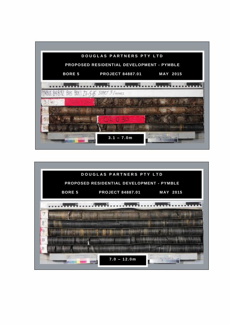
D O U G L A S P A R T N E R S P T Y L T D
PROPOSED RESIDENTIAL DEVELOPMENT - PYMBLE
BORE 5 PROJECT 84887.01 MAY 2015
3 . 1 – 7 . 0 m
D O U G L A S P A R T N E R S P T Y L T D
PROPOSED RESIDENTIAL DEVELOPMENT - PYMBLE
BORE 5 PROJECT 84887.01 M AY 2015
7 . 0 – 1 2 . 0 m
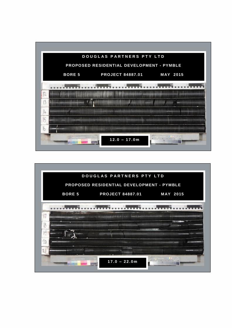
D O U G L A S P A R T N E R S P T Y L T D
PROPOSED RESIDENTIAL DEVELOPMENT - PYMBLE
BORE 5 PROJECT 84887.01 MAY 2015
1 2 . 0 – 1 7 . 0 m
D O U G L A S P A R T N E R S P T Y L T D
PROPOSED RESIDENTIAL DEVELOPMENT - PYMBLE
BORE 5 PROJECT 84887.01 M AY 2015
1 7 . 0 – 2 2 . 0 m
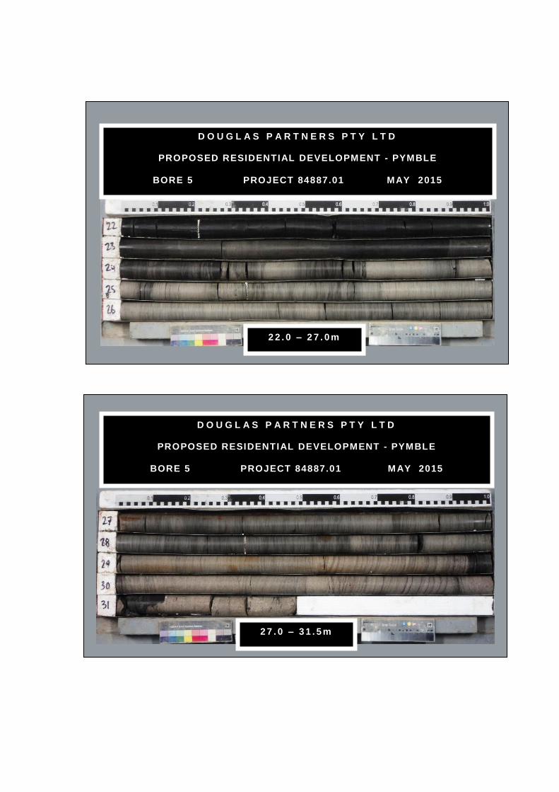
D O U G L A S P A R T N E R S P T Y L T D
PROPOSED RESIDENTIAL DEVELOPMENT - PYMBLE
BORE 5 PROJECT 84887.01 MAY 2015
2 2 . 0 – 2 7 . 0 m
D O U G L A S P A R T N E R S P T Y L T D
PROPOSED RESIDENTIAL DEVELOPMENT - PYMBLE
BORE 5 PROJECT 84887.01 M AY 2015
2 7 . 0 – 3 1 . 5 m

Note: Unless otherwisestated, rock is fracturedalong rough planarbedding dipping 0°- 10°
1.5m: J70°, pl, ro, fe1.62m: J75°, pl, ro, cly1.7-1.73m: Cs1.78-1.94m: B (x3) 5°,Cz, 10-15mm2.1m: CORE LOSS:240mm2.34-2.6m: fg, fe
2.77 & 2.97m: B20°, fe
3.05m: J70°, un, ro, fe
3.2m: J45°, pl, ro, fe
3.36m: J25°, pl, ro, fe
3.64m: J35°, un, ro, cln3.78m: J30°, un, ro, fe3.85m: J30°, un, ro, fe3.95m: J45°, pl, ro, fe4m: J75°, un, ro, cln4.3 -4.6m: B's 5°- 10°, fe
4.68m: J45° - 50°, cu,ro, fe
6.05m: J35°, un, ro, fe6.14-6.36m: B's 0°, fe
6.4m: J40°, pl, ro, fe6.5m: J (x4) 30°- 35°, pl,ro, fe
7m: J60°, un, ro, fe, cly
7.15 & 7.2m: J45°- 50°,un, ro, fe7.4-7.6m: B's 0°, cly
8m: J80°, pl, sm, cln
8.4-8.7m: fg
TOPSOIL - brown, clayey silttopsoil with some rootlets andsurficial vegetation
CLAY - apparently firm to stiff, lightgrey-brown, clay with ironstonegravel, moist
LAMINITE - very low to lowstrength, light brown to red-brownlaminite (interbedded siltstone andsandstone)
LAMINITE - medium strength,highly to moderately weathered,highly fractured to fractured,grey-brown laminite (siltstoneinterbedded with approximately20% fine grained sandstonelaminations) and some very lowstrength bands
LAMINITE - medium then highstrength, moderately weathered,fractured, grey-brown laminite(siltstone interbedded withapproximately 25-30% fine grainedsandstone laminations)
LAMINITE - high strength,moderately weathered, fractured,grey-brown laminite (siltstoneinterbedded with approximately25-30% fine grained sandstonelaminations)
SILTSTONE - high and mediumstrength, slightly weathered,fragmented and slightly fractured,grey-brown, siltstone withapproximately 5-10% finesandstone laminations
SILTSTONE - high strength, fresh,fragmented and slightly fractured,grey, siltstone with approximately5-10% fine sandstone laminations
25/50mmrefusal
PL(A) = 0.9
PL(A) = 0.8
PL(A) = 0.7
PL(A) = 0.7
PL(A) = 1.1
PL(A) = 1.3
PL(A) = 2.4
PL(A) = 1.4
PL(A) = 1.7
0
0
35
82
92
100
100
100
A
A
AS
C
C
C
C
0.05
0.4
1.15
2.342.35
5.2
7.2
8.7
FractureSpacing
(m)
0.01
Depth(m) B - Bedding
S - Shear
RockStrength
Type
Sampling & In Situ Testing
Ex Low
Very Low
Low
Medium
High
Very H
igh
Ex H
igh
0.10
0.50
1.00 RQD
%
Core
Rec. %
Graphic
Log
Water
Degree ofWeathering
EW
HW
MW
SW
FS
FR
Description
of
Strata
1
2
3
4
5
6
7
8
9
J - Joint
F - Fault
RL
137
136
135
134
133
132
131
130
129
128
Test Results&
Comments0.05
Discontinuities
BOREHOLE LOG BOREHOLE LOG BOREHOLE LOG BOREHOLE LOG BOREHOLE LOG BOREHOLE LOG BOREHOLE LOG
CLIENT:
PROJECT:
LOCATION: 1 Avon Road, Pymble
SAMPLING & IN SITU TESTING LEGENDA Auger sample G Gas sample PID Photo ionisation detector (ppm)B Bulk sample P Piston sample PL(A) Point load axial test Is(50) (MPa)BLK Block sample Ux Tube sample (x mm dia.) PL(D) Point load diametral test Is(50) (MPa)C Core drilling W Water sample pp Pocket penetrometer (kPa)D Disturbed sample Water seep S Standard penetration testE Environmental sample Water level V Shear vane (kPa)
BORE No: 6
PROJECT No: 84887.01
DATE: 10/6/2015
SHEET 1 OF 2
DRILLER: SM LOGGED: SI CASING: HW to 1.15m
Ausbao Pymble Pty Ltd
Proposed Residential Development
REMARKS:
RIG: DT 100
WATER OBSERVATIONS:
TYPE OF BORING:
No free groundwater observed whilst augering
Solid flight auger to 1.0m; Rotary to1.15m; NMLC-Coring to 14.35m
SURFACE LEVEL: 137.2 AHD
EASTING: 327431
NORTHING: 6264759
DIP/AZIMUTH: 90°/--
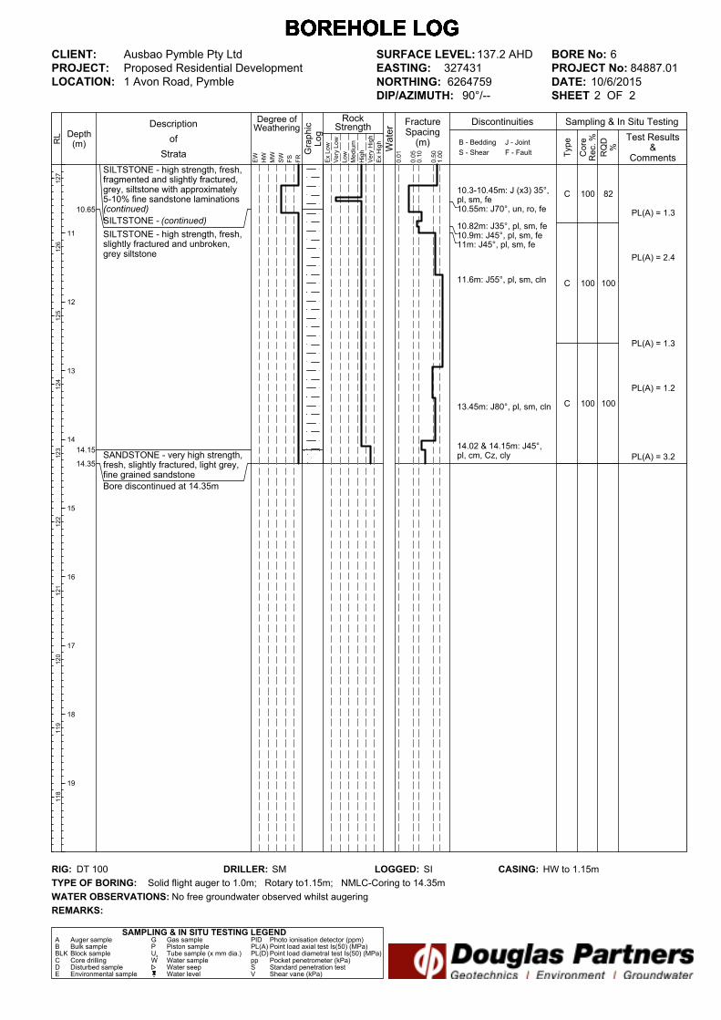
10.3-10.45m: J (x3) 35°,pl, sm, fe10.55m: J70°, un, ro, fe
10.82m: J35°, pl, sm, fe10.9m: J45°, pl, sm, fe11m: J45°, pl, sm, fe
11.6m: J55°, pl, sm, cln
13.45m: J80°, pl, sm, cln
14.02 & 14.15m: J45°,pl, cm, Cz, cly
SILTSTONE - high strength, fresh,fragmented and slightly fractured,grey, siltstone with approximately5-10% fine sandstone laminations(continued)
SILTSTONE - (continued)
SILTSTONE - high strength, fresh,slightly fractured and unbroken,grey siltstone
SANDSTONE - very high strength,fresh, slightly fractured, light grey,fine grained sandstone
Bore discontinued at 14.35m
PL(A) = 1.3
PL(A) = 2.4
PL(A) = 1.3
PL(A) = 1.2
PL(A) = 3.2
82
100
100
100
100
100
C
C
C
10.65
14.15
14.35
FractureSpacing
(m)
0.01
Depth(m) B - Bedding
S - Shear
RockStrength
Type
Sampling & In Situ Testing
Ex Low
Very Low
Low
Medium
High
Very H
igh
Ex H
igh
0.10
0.50
1.00 RQD
%
Core
Rec. %
Graphic
Log
Water
Degree ofWeathering
EW
HW
MW
SW
FS
FR
Description
of
Strata
11
12
13
14
15
16
17
18
19
J - Joint
F - Fault
RL
127
126
125
124
123
122
121
120
119
118
Test Results&
Comments0.05
Discontinuities
BOREHOLE LOG BOREHOLE LOG BOREHOLE LOG BOREHOLE LOG BOREHOLE LOG BOREHOLE LOG BOREHOLE LOG
CLIENT:
PROJECT:
LOCATION: 1 Avon Road, Pymble
SAMPLING & IN SITU TESTING LEGENDA Auger sample G Gas sample PID Photo ionisation detector (ppm)B Bulk sample P Piston sample PL(A) Point load axial test Is(50) (MPa)BLK Block sample Ux Tube sample (x mm dia.) PL(D) Point load diametral test Is(50) (MPa)C Core drilling W Water sample pp Pocket penetrometer (kPa)D Disturbed sample Water seep S Standard penetration testE Environmental sample Water level V Shear vane (kPa)
BORE No: 6
PROJECT No: 84887.01
DATE: 10/6/2015
SHEET 2 OF 2
DRILLER: SM LOGGED: SI CASING: HW to 1.15m
Ausbao Pymble Pty Ltd
Proposed Residential Development
REMARKS:
RIG: DT 100
WATER OBSERVATIONS:
TYPE OF BORING:
No free groundwater observed whilst augering
Solid flight auger to 1.0m; Rotary to1.15m; NMLC-Coring to 14.35m
SURFACE LEVEL: 137.2 AHD
EASTING: 327431
NORTHING: 6264759
DIP/AZIMUTH: 90°/--
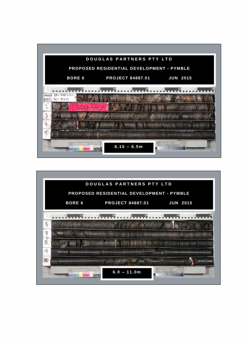
D O U G L A S P A R T N E R S P T Y L T D
PROPOSED RESIDENTIAL DEVELOPMENT - PYMBLE
BORE 6 PROJECT 84887.01 JUN 2015
6 . 1 5 – 6 . 0 m
D O U G L A S P A R T N E R S P T Y L T D
PROPOSED RESIDENTIAL DEVELOPMENT - PYMBLE
BORE 6 PROJECT 84887.01 JUN 2015
6 . 0 – 1 1 . 0 m
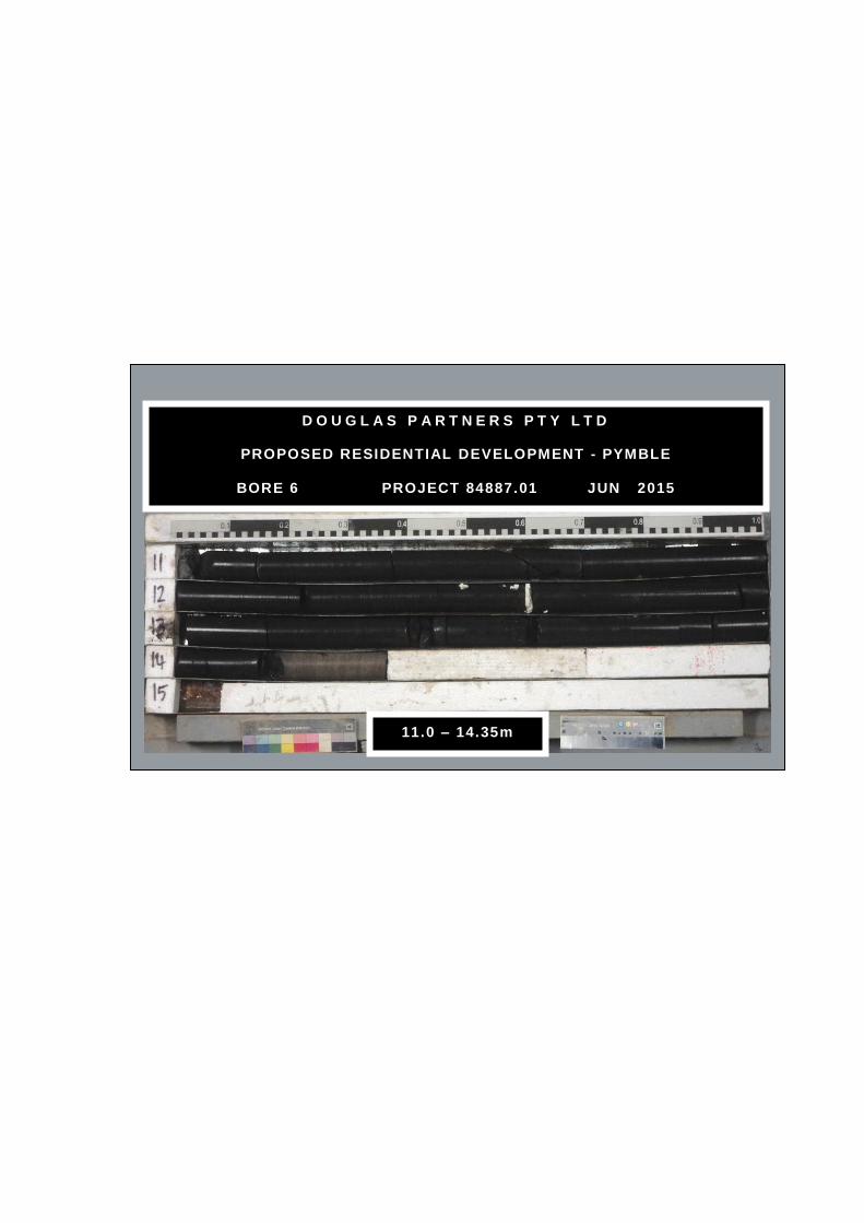
D O U G L A S P A R T N E R S P T Y L T D
PROPOSED RESIDENTIAL DEVELOPMENT - PYMBLE
BORE 6 PROJECT 84887.01 JUN 2015
11.0 – 14.35m

>>
Note: Unless otherwisestated, rock is fracturedalong rough planarbedding dipping 0°- 10°
4m: CORE LOSS:480mm
4.48-5.5m: B's 0°- 5°,fe,cly
5.5-5.75m: J,sv (85°-90°), un, ro, fe
5.9-7.05m: B's 0°, fe
7.93 & 7.96m: B's 0°, fe
TOPSOIL - brown, clayey silttopsoil with some rootlets andsurficial vegetation
FILLING - grey to grey-brown, siltyclay filling with a trace of concreteand ironstone gravel, moist
SILTY CLAY - apparently stiff,brown, silty clay with a trace of fineironstone gravel, moist
LAMINITE - very low to lowstrength, grey-brown laminite(interbedded siltstone andsandstone)
LAMINITE - medium strength,extremely to highly weathered,fragmented to fractured,grey-brown laminite (siltstoneinterbedded with approximately25% fine sandstone laminations)and some extremely low and verylow strength bands
LAMINITE - medium strength,moderately weathered, fragmentedand fractured, grey-brown laminite(siltstone interbedded withapproximately 30% fine sandstonelaminations)
LAMINITE - high and high to veryhigh strength, fresh, slightlyfractured and unbroken, light greyto grey, laminite (siltstoneinterbedded with approximately20% fine sandstone laminations)
5,7,12N = 19
27/150mmrefusal
PL(A) = 0.6
PL(A) = 0.6
PL(A) = 0.8
PL(A) = 2.2
PL(A) = 2.3
PL(A) = 3.1
0
68
98
81
100
100
A
A
A
S
S
C
C
C
0.1
0.6
1.3
4.0
4.48
6.15
7.05
10.0
FractureSpacing(m)
0.01
Depth(m) B - Bedding
S - Shear
RockStrength
Type
Sampling & In Situ Testing
Ex Low
Very Low
Low
Medium
High
Very High
Ex High
0.10
0.50
1.00 RQD
%
Core
Rec. %
Graphic
Log
Water
Degree ofWeathering
EW
HW
MW
SW
FS
FR
Description
of
Strata
1
2
3
4
5
6
7
8
9
J - Joint
F - Fault
RL
140
139
138
137
136
135
134
133
132
131
Test Results&
Comments0.05
Discontinuities
BOREHOLE LOG BOREHOLE LOG BOREHOLE LOG BOREHOLE LOG BOREHOLE LOG BOREHOLE LOG BOREHOLE LOG
CLIENT:
PROJECT:
LOCATION: 1 Avon Road, Pymble
SAMPLING & IN SITU TESTING LEGENDA Auger sample G Gas sample PID Photo ionisation detector (ppm)B Bulk sample P Piston sample PL(A) Point load axial test Is(50) (MPa)BLK Block sample Ux Tube sample (x mm dia.) PL(D) Point load diametral test Is(50) (MPa)C Core drilling W Water sample pp Pocket penetrometer (kPa)D Disturbed sample Water seep S Standard penetration testE Environmental sample Water level V Shear vane (kPa)
BORE No: 7
PROJECT No: 84887.01
DATE: 28/5/2015
SHEET 1 OF 2
DRILLER: SY LOGGED: SI CASING: HW to 2.5m
Ausbao Pymble Pty Ltd
Proposed Residential Development
REMARKS:
RIG: Bobcat
WATER OBSERVATIONS:
TYPE OF BORING: Solid flight auger to 2.5m; Rotary to 4.0m; NMLC-Coring to 18.33m
SURFACE LEVEL: 140.7 AHD
EASTING: 327465
NORTHING: 6264776
DIP/AZIMUTH: 90°/--
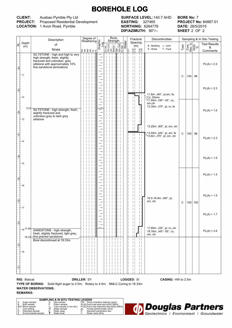
11.8m: J45°, pl,sm, fe,Cz, 20mm11.94m: J30°- 45°, cu,sm,cln12.35m: J70°, pl, ro, fe
13.25m: J65°, pl, sm, cln
13.55m: J45°, pl, sm, fe13.6m: J75°, pl, sm, cln
16.5-16.9m: J90°, pl,sm, cln
17.85m: J35°, pl, ro, cln
18.16m: J45°- 55°, cu,sm, cln
SILTSTONE - high and high to veryhigh strength, fresh, slightlyfractured and unbroken, greysiltstone with approximately 10%fine sandstone laminations
SILTSTONE - high strength, fresh,slightly fractured andunbroken,grey to dark greysiltstone
SANDSTONE - high strength,fresh, slightly fractured, light grey,fine grained sandstone
Bore discontinued at 18.33m
PL(A) = 2.3
PL(A) = 2.3
PL(A) = 1.6
PL(A) = 2.3
PL(A) = 1.5
PL(A) = 1.5
PL(A) = 1.5
PL(A) = 1.7
PL(A) = 2.6
98
98
100
100
100
100
C
C
C
12.5
17.95
18.33
FractureSpacing(m)
0.01
Depth(m) B - Bedding
S - Shear
RockStrength
Type
Sampling & In Situ Testing
Ex Low
Very Low
Low
Medium
High
Very High
Ex High
0.10
0.50
1.00 RQD
%
Core
Rec. %
Graphic
Log
Water
Degree ofWeathering
EW
HW
MW
SW
FS
FR
Description
of
Strata
11
12
13
14
15
16
17
18
19
J - Joint
F - Fault
RL
130
129
128
127
126
125
124
123
122
121
Test Results&
Comments0.05
Discontinuities
BOREHOLE LOG BOREHOLE LOG BOREHOLE LOG BOREHOLE LOG BOREHOLE LOG BOREHOLE LOG BOREHOLE LOG
CLIENT:
PROJECT:
LOCATION: 1 Avon Road, Pymble
SAMPLING & IN SITU TESTING LEGENDA Auger sample G Gas sample PID Photo ionisation detector (ppm)B Bulk sample P Piston sample PL(A) Point load axial test Is(50) (MPa)BLK Block sample Ux Tube sample (x mm dia.) PL(D) Point load diametral test Is(50) (MPa)C Core drilling W Water sample pp Pocket penetrometer (kPa)D Disturbed sample Water seep S Standard penetration testE Environmental sample Water level V Shear vane (kPa)
BORE No: 7
PROJECT No: 84887.01
DATE: 28/5/2015
SHEET 2 OF 2
DRILLER: SY LOGGED: SI CASING: HW to 2.5m
Ausbao Pymble Pty Ltd
Proposed Residential Development
REMARKS:
RIG: Bobcat
WATER OBSERVATIONS:
TYPE OF BORING: Solid flight auger to 2.5m; Rotary to 4.0m; NMLC-Coring to 18.33m
SURFACE LEVEL: 140.7 AHD
EASTING: 327465
NORTHING: 6264776
DIP/AZIMUTH: 90°/--

D O U G L A S P A R T N E R S P T Y L T D
PROPOSED RESIDENTIAL DEVELOPMENT - PYMBLE
BORE 7 PROJECT 84887.01 MAY 2015
4 . 0 – 8 . 0 m
D O U G L A S P A R T N E R S P T Y L T D
PROPOSED RESIDENTIAL DEVELOPMENT - PYMBLE
BORE 7 PROJECT 84887.01 M AY 2015
8 . 0 – 1 3 . 0 m

D O U G L A S P A R T N E R S P T Y L T D
PROPOSED RESIDENTIAL DEVELOPMENT - PYMBLE
BORE 7 PROJECT 84887.01 MAY 2015
1 3 . 0 – 1 8 . 0 m
D O U G L A S P A R T N E R S P T Y L T D
PROPOSED RESIDENTIAL DEVELOPMENT - PYMBLE
BORE 7 PROJECT 84887.01 M AY 2015
1 8 . 0 – 1 8 . 3 3 m
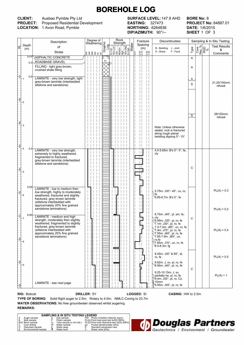
Note: Unless otherwisestated, rock is fracturedalong rough planarbedding dipping 0°- 10°
4.0-5.65m: B's 0°- 5°, fe,cly
5.75m: J30°- 45°, cu, ro,fe5.85-6.7m: B's 0°, fe
6.75m: J45°, pl, sm, fe,cly6.95m: J35°, pl, ro, fe7.1m: J30°, pl, ro, fe7.3-7.4m: J85°, un, ro, fe7.4m: J70°, pl, ro, fe7.55m: J65°, pl, ro, fe7.65-7.9m: J85°, un,ro,fe7.85m: J70°, un, ro, fe8.0-8.3m: fg
8.45m: J30° & 65°, st,ro, fe
8.82m: J, sv, pl, ro, fe8.95m: J40°, pl, ro, fe
9.25-10.15m: J, sv,partially he, pl, ro, fe9.4m: J35°, pl, ro, Cz,10mm9.55m: J45°, pl, ro, fe
ASPHALTIC CONCRETE
ROADBASE GRAVEL
FILLING - light grey-brown,crushed shale filling
LAMINITE - very low strength, lightgrey-brown laminite (interbeddedsiltstone and sandstone)
LAMINITE - very low strength,extremely to highly weathered,fragmented to fractured,grey-brown laminite (interbeddedsiltstone and sandstone)
LAMINITE - low to medium thenlow strength, highly to moderatelyweathered, fractured and slightlyfractured, grey brown laminite(siltstone interbedded withapproximately 20% fine grainedsandstone laminations)
LAMINITE - medium and highstrength, moderately then slightlyweathered, fragmented to slightlyfractured, grey-brown laminite(siltstone interbedded withapproximately 20% fine grainedsandstone laminations)
LAMINITE - see next page
21,20/100mmrefusal
28/150mmrefusal
PL(A) = 0.3
PL(A) = 0.2
PL(A) = 0.4
PL(A) = 0.5
PL(A) = 1
A
A
A
S
S
C
C
C
0.01
0.3
0.9
4.0
5.65
6.85
FractureSpacing(m)
0.01
Depth(m) B - Bedding
S - Shear
RockStrength
Type
Sampling & In Situ Testing
Ex Low
Very Low
Low
Medium
High
Very High
Ex High
0.10
0.50
1.00 RQD
%
Core
Rec. %
Graphic
Log
Water
Degree ofWeathering
EW
HW
MW
SW
FS
FR
Description
of
Strata
1
2
3
4
5
6
7
8
9
J - Joint
F - Fault
RL
147
146
145
144
143
142
141
140
139
138
Test Results&
Comments0.05
Discontinuities
BOREHOLE LOG BOREHOLE LOG BOREHOLE LOG BOREHOLE LOG BOREHOLE LOG BOREHOLE LOG BOREHOLE LOG
CLIENT:
PROJECT:
LOCATION: 1 Avon Road, Pymble
SAMPLING & IN SITU TESTING LEGENDA Auger sample G Gas sample PID Photo ionisation detector (ppm)B Bulk sample P Piston sample PL(A) Point load axial test Is(50) (MPa)BLK Block sample Ux Tube sample (x mm dia.) PL(D) Point load diametral test Is(50) (MPa)C Core drilling W Water sample pp Pocket penetrometer (kPa)D Disturbed sample Water seep S Standard penetration testE Environmental sample Water level V Shear vane (kPa)
BORE No: 8
PROJECT No: 84887.01
DATE: 1/6/2015
SHEET 1 OF 3
DRILLER: SY LOGGED: SI CASING: HW to 2.5m
Ausbao Pymble Pty Ltd
Proposed Residential Development
REMARKS:
RIG: Bobcat
WATER OBSERVATIONS:
TYPE OF BORING:
No free groundwater observed whilst augering
Solid flight auger to 2.5m; Rotary to 4.0m; NMLC-Coring to 23.7m
SURFACE LEVEL: 147.9 AHD
EASTING: 327473
NORTHING: 6264836
DIP/AZIMUTH: 90°/--
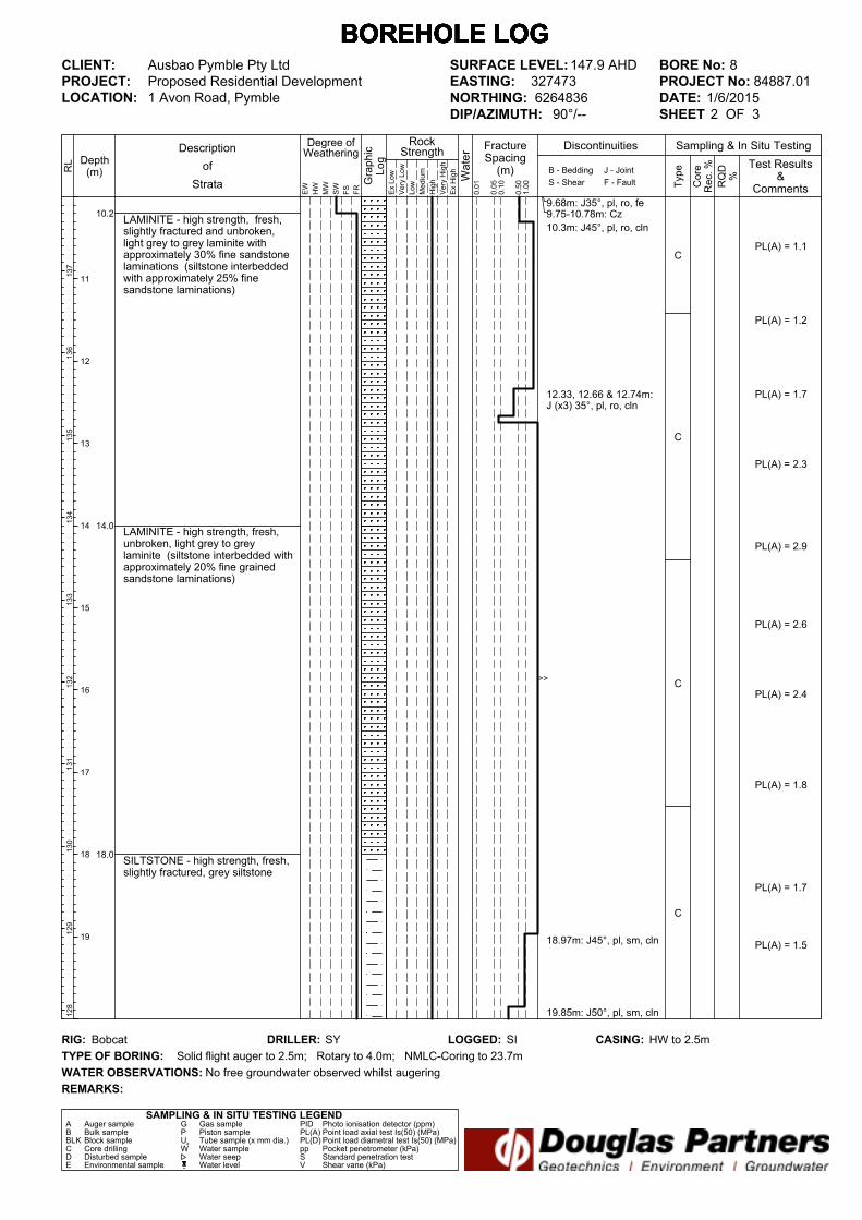
>>
9.68m: J35°, pl, ro, fe9.75-10.78m: Cz
10.3m: J45°, pl, ro, cln
12.33, 12.66 & 12.74m:J (x3) 35°, pl, ro, cln
18.97m: J45°, pl, sm, cln
19.85m: J50°, pl, sm, cln
LAMINITE - high strength, fresh,slightly fractured and unbroken,light grey to grey laminite withapproximately 30% fine sandstonelaminations (siltstone interbeddedwith approximately 25% finesandstone laminations)
LAMINITE - high strength, fresh,unbroken, light grey to greylaminite (siltstone interbedded withapproximately 20% fine grainedsandstone laminations)
SILTSTONE - high strength, fresh,slightly fractured, grey siltstone
PL(A) = 1.1
PL(A) = 1.2
PL(A) = 1.7
PL(A) = 2.3
PL(A) = 2.9
PL(A) = 2.6
PL(A) = 2.4
PL(A) = 1.8
PL(A) = 1.7
PL(A) = 1.5
C
C
C
C
10.2
14.0
18.0
FractureSpacing(m)
0.01
Depth(m) B - Bedding
S - Shear
RockStrength
Type
Sampling & In Situ Testing
Ex Low
Very Low
Low
Medium
High
Very High
Ex High
0.10
0.50
1.00 RQD
%
Core
Rec. %
Graphic
Log
Water
Degree ofWeathering
EW
HW
MW
SW
FS
FR
Description
of
Strata
11
12
13
14
15
16
17
18
19
J - Joint
F - Fault
RL
137
136
135
134
133
132
131
130
129
128
Test Results&
Comments0.05
Discontinuities
BOREHOLE LOG BOREHOLE LOG BOREHOLE LOG BOREHOLE LOG BOREHOLE LOG BOREHOLE LOG BOREHOLE LOG
CLIENT:
PROJECT:
LOCATION: 1 Avon Road, Pymble
SAMPLING & IN SITU TESTING LEGENDA Auger sample G Gas sample PID Photo ionisation detector (ppm)B Bulk sample P Piston sample PL(A) Point load axial test Is(50) (MPa)BLK Block sample Ux Tube sample (x mm dia.) PL(D) Point load diametral test Is(50) (MPa)C Core drilling W Water sample pp Pocket penetrometer (kPa)D Disturbed sample Water seep S Standard penetration testE Environmental sample Water level V Shear vane (kPa)
BORE No: 8
PROJECT No: 84887.01
DATE: 1/6/2015
SHEET 2 OF 3
DRILLER: SY LOGGED: SI CASING: HW to 2.5m
Ausbao Pymble Pty Ltd
Proposed Residential Development
REMARKS:
RIG: Bobcat
WATER OBSERVATIONS:
TYPE OF BORING:
No free groundwater observed whilst augering
Solid flight auger to 2.5m; Rotary to 4.0m; NMLC-Coring to 23.7m
SURFACE LEVEL: 147.9 AHD
EASTING: 327473
NORTHING: 6264836
DIP/AZIMUTH: 90°/--

20.04m: J35°, un, ro, cln
20.4-20.5m: J85°, pl, ro,cln20.56m: J45°, sl, sm, cln20.72m: J45°, pl, sm,Cz, 10mm20.82m: J50°, pl, sm, ci20.95m: J50°, pl, ro, cln21.05m: J50° & 85°, st,ro, cln21.36m: J990°, un, ro,cln
22.2m: J80°, pl, sm, cln22.25-22.5m: Sz22.45-22.5m: Cz
22.86m: J40°, pl, sm,cln
SILTSTONE - high strength, fresh,slightly fractured, grey siltstone(continued)
Bore discontinued at 23.7m
PL(A) = 1.8
PL(A) = 1.1
PL(A) = 1.3
PL(A) = 1.8
C
C
23.7
FractureSpacing(m)
0.01
Depth(m) B - Bedding
S - Shear
RockStrength
Type
Sampling & In Situ Testing
Ex Low
Very Low
Low
Medium
High
Very High
Ex High
0.10
0.50
1.00 RQD
%
Core
Rec. %
Graphic
Log
Water
Degree ofWeathering
EW
HW
MW
SW
FS
FR
Description
of
Strata
21
22
23
24
25
26
27
28
29
J - Joint
F - Fault
RL
127
126
125
124
123
122
121
120
119
118
Test Results&
Comments0.05
Discontinuities
BOREHOLE LOG BOREHOLE LOG BOREHOLE LOG BOREHOLE LOG BOREHOLE LOG BOREHOLE LOG BOREHOLE LOG
CLIENT:
PROJECT:
LOCATION: 1 Avon Road, Pymble
SAMPLING & IN SITU TESTING LEGENDA Auger sample G Gas sample PID Photo ionisation detector (ppm)B Bulk sample P Piston sample PL(A) Point load axial test Is(50) (MPa)BLK Block sample Ux Tube sample (x mm dia.) PL(D) Point load diametral test Is(50) (MPa)C Core drilling W Water sample pp Pocket penetrometer (kPa)D Disturbed sample Water seep S Standard penetration testE Environmental sample Water level V Shear vane (kPa)
BORE No: 8
PROJECT No: 84887.01
DATE: 1/6/2015
SHEET 3 OF 3
DRILLER: SY LOGGED: SI CASING: HW to 2.5m
Ausbao Pymble Pty Ltd
Proposed Residential Development
REMARKS:
RIG: Bobcat
WATER OBSERVATIONS:
TYPE OF BORING:
No free groundwater observed whilst augering
Solid flight auger to 2.5m; Rotary to 4.0m; NMLC-Coring to 23.7m
SURFACE LEVEL: 147.9 AHD
EASTING: 327473
NORTHING: 6264836
DIP/AZIMUTH: 90°/--

D O U G L A S P A R T N E R S P T Y L T D
PROPOSED RESIDENTIAL DEVELOPMENT - PYMBLE
BORE 8 PROJECT 84887.01 JUN 2015
4 . 0 – 8 . 0 m
D O U G L A S P A R T N E R S P T Y L T D
PROPOSED RESIDENTIAL DEVELOPMENT - PYMBLE
BORE 8 PROJECT 84887.01 JUN 2015
8 . 0 – 1 3 . 0 m
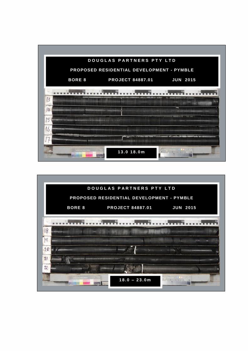
D O U G L A S P A R T N E R S P T Y L T D
PROPOSED RESIDENTIAL DEVELOPMENT - PYMBLE
BORE 8 PROJECT 84887.01 JUN 2015
1 3 . 0 1 8 . 0 m
D O U G L A S P A R T N E R S P T Y L T D
PROPOSED RESIDENTIAL DEVELOPMENT - PYMBLE
BORE 8 PROJECT 84887.01 JUN 2015
1 8 . 0 – 2 3 . 0 m

D O U G L A S P A R T N E R S P T Y L T D
PROPOSED RESIDENTIAL DEVELOPMENT - PYMBLE
BORE 8 PROJECT 84887.01 JUN 2015
23.0 – 23.7m

Appendix D
Vibration Notes

Page 1 of 3
Ground Vibration
Ground vibration can be described by measurement of the acceleration, velocity or displacement of the
ground particles at one or more locations. Triaxial geophone sensors for example can measure the peak
velocities of radial, transverse or vertical particle motion (designated PPVr, PPVt and PPVz respectively
and PPVi for any directional component) within selected sample periods and peak velocities can also be
determined in the resultant direction of particle motion, from calculations of instantaneous vector sums
throughout the sample period. Vector sum velocities are designated VSPPV, or in many cases simply
PPV.
There are three aspects of vibration which need to be assessed:
1. Effects on structures
2. Effects on architectural finishes
3. Effects on humans
Numerous standards and guidelines exist worldwide which provide a basis for these assessments. Their
focus varies from structural damage to human comfort and from transient to intermittent to continuous
vibrations. Most provide guideline vibration limits for protection against damage or human discomfort,
however these limits are not always consistent and application of a particular standard or guideline should
be based on the expected type of vibration, the types and conditions of the potentially affected buildings
and the potential for discomfort of their occupants.
Both the guideline and the vibration limits should be determined on a case by case basis and the adopted
limits (damage and human comfort or the lower of the two) may differ from the guideline values,
according to the experience of the vibration consultant, due to the sensitivity of the building or the
activities of its occupants. Some applicable guidelines are summarised in the graph on the following
page.
Depending on site conditions, proposed works, results of building condition surveys and on-site vibration
trials (indicating vibration attenuation rates and dominant vibration frequencies of excavation plant), the
standards, guidelines and limits discussed below are considered appropriate for management of ground
vibrations generated during rock excavation.
Effects on Structures
The German Standard DIN4150-3-1999 “Structural vibration – effects of vibrations on structures”,
recommends that ground vibration at foundation level of residential buildings, in good condition bearing
on sound rock foundations, be limited to 5 - 15 - 20 mm/s PPVi (at vibration frequencies of 10 - 50 - 100
Hz typical of excavation plant), in order to reduce the potential for structural damage. Higher limits (20 -
40 - 50 mm/s PPVi) and lower limits (3 - 8 -10 mm/s PPVi) are recommended for commercial/industrial
and sensitive buildings respectively. From DP experience where buildings are bearing on loose sand,
maximum vibration levels should be significantly reduced to the order of 5 to 7 mm/s VSPPV to reduce
the risk of vibration-induced sand densification and settlement.
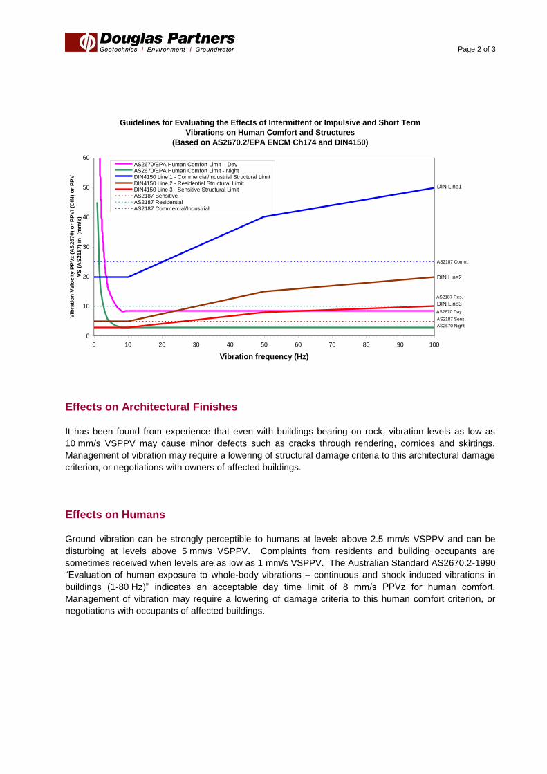
Page 2 of 3
Effects on Architectural Finishes
It has been found from experience that even with buildings bearing on rock, vibration levels as low as
10 mm/s VSPPV may cause minor defects such as cracks through rendering, cornices and skirtings.
Management of vibration may require a lowering of structural damage criteria to this architectural damage
criterion, or negotiations with owners of affected buildings.
Effects on Humans
Ground vibration can be strongly perceptible to humans at levels above 2.5 mm/s VSPPV and can be
disturbing at levels above 5 mm/s VSPPV. Complaints from residents and building occupants are
sometimes received when levels are as low as 1 mm/s VSPPV. The Australian Standard AS2670.2-1990
“Evaluation of human exposure to whole-body vibrations – continuous and shock induced vibrations in
buildings (1-80 Hz)” indicates an acceptable day time limit of 8 mm/s PPVz for human comfort.
Management of vibration may require a lowering of damage criteria to this human comfort criterion, or
negotiations with occupants of affected buildings.
Guidelines for Evaluating the Effects of Intermittent or Impulsive and Short Term
Vibrations on Human Comfort and Structures
(Based on AS2670.2/EPA ENCM Ch174 and DIN4150)
0
10
20
30
40
50
60
0 10 20 30 40 50 60 70 80 90 100
Vibration frequency (Hz)
Vib
rati
on
Ve
loc
ity
PP
Vz (
AS
26
70
) o
r P
PV
i (D
IN)
or
PP
V-
VS
(A
S2
18
7)
in
(mm
/s)
AS2670/EPA Human Comfort Limit - DayAS2670/EPA Human Comfort Limit - NightDIN4150 Line 1 - Commercial/Industrial Structural LimitDIN4150 Line 2 - Residential Structural LimitDIN4150 Line 3 - Sensitive Structural LimitAS2187 SensitiveAS2187 ResidentialAS2187 Commercial/Industrial
AS2670 Day
DIN Line1
DIN Line2
DIN Line3
AS2670 Night
AS2187 Sens.
AS2187 Comm.
AS2187 Res.

Page 3 of 3
Vibration Dosage
A vibration limit based on a particle velocity allows real time control of excavation using warning systems
(e.g. flashing lights) attached to vibration monitors. Occasional exceedances (vibration levels exceeding
the allowed limit) are not damaging or disturbing and can be allowed but frequent exceedances should be
avoided by changes in excavation methods. The difference between occasional and frequent is difficult
to gauge on site but can be assessed using recorded vibration data, on the basis of experience or by
application of a vibration dosage criterion.
A vibration dosage value (VDV) can be used to assess the effect of intermittent vibrations (e.g. from
bursts of rock hammering) on humans over a defined period. Acceptable dosages (generally VDVz for
vertical vibrations found most disturbing by humans) have been defined for occupants of residential,
commercial and industrial buildings (“Assessing Vibration: a technical guideline”, Department of
Environment and Conservation, 2006). Estimates of VDV (eVDV) can be calculated from recorded
vibration data and can be compared with recommended maxima of 0.4, 0.8 and 1.6 m/s1.75
for residential,
commercial and industrial locations respectively, to assess the need to change excavation methods to
restore human comfort.
The vibration dosage guideline does not relate VDV to structural damage however it is considered that if
the VDV is acceptable from a human comfort viewpoint, vibrations leading to that VDV would be unlikely
to cause damage to the corresponding residential, commercial or industrial structure.
Management of vibrations may require addition of these vibration dosage criteria to other human comfort
or damage criteria, if the frequency of vibration exceedances becomes difficult to assess on site or by
experienced-based data review.