report on best available techniques (bat) in german … · report on best available techniques...
TRANSCRIPT

Report on Best Available Techniques (BAT) in
German Zinc and Lead Production
FINAL DRAFT
Deutsch-Französisches Institut für Umweltforschung (DFIU) French-German Institute for Environmental Research
University of Karlsruhe (TH) o. Prof. Dr. O. Rentz
Dipl.-Ing. Stephan Hähre, Dr. Frank Schultmann
Karlsruhe, February 1999
On behalf of the German Federal Environmental Agency, Berlin (UBA) in the frame of the Research Project 109 05 006


Contents
3
Contents PREFACE.............................................................................................................................................................13
1 GENERAL INFORMATION.......................................................................................................................... 15
1.1 PRODUCTION AND USE OF ZINC AND LEAD ................................................................................................... 15 1.1.1 Zinc ..................................................................................................................................................... 15 1.1.2 Lead .................................................................................................................................................... 16
1.2 FIRST INDICATION OF ENVIRONMENTAL CONCERNS REGARDING THE PRODUCTION OF ZINC AND LEAD ........ 19 1.2.1 Emissions into the atmosphere............................................................................................................ 19 1.2.2 Potential releases into water............................................................................................................... 21 1.2.3 Solid materials generated ................................................................................................................... 21
2 APPLIED PROCESS TECHNOLOGY AND ABATEMENT TECHNIQUES IN GERMAN ZINC AND LEAD PRODUCTION........................................................................................................................................ 23
2.1 INTRODUCTION AND SCOPE OF THE STUDY................................................................................................... 23 2.2 BASIC DESCRIPTION OF ZINC AND LEAD PRODUCTION .................................................................................. 24
2.2.1 Zinc production................................................................................................................................... 24 2.2.1.1 Hydrometallurgical zinc production ............................................................................................................. 25
2.2.1.1.1 General process description .................................................................................................................. 25 2.2.1.1.2 Main outputs and environmental concerns of the hydrometallurgical zinc production processes ........ 27
2.2.1.2 Pyrometallurgical zinc production ................................................................................................................ 29 2.2.1.2.1 Imperial Smelting Process .................................................................................................................... 29 2.2.1.2.2 Waelz kiln process................................................................................................................................ 34 2.2.1.2.3 Reduction in vertical retorts (New Jersey retort process route) ............................................................ 36 2.2.1.2.4 Fuming plant......................................................................................................................................... 37 2.2.1.2.5 Melting of metallic raw materials ......................................................................................................... 37 2.2.1.2.6 Refining of crude zinc .......................................................................................................................... 38
2.2.1.3 Zinc production plants in Germany............................................................................................................... 38 2.2.2 Lead production.................................................................................................................................. 41
2.2.2.1 Lead-containing raw materials ...................................................................................................................... 41 2.2.2.2 Sinter plant - blast furnace route for lead production.................................................................................... 42 2.2.2.3 New direct smelting processes for lead production....................................................................................... 44 2.2.2.4 Lead production from secondary raw material.............................................................................................. 45
2.2.2.4.1 Preparation of battery and scrap materials ............................................................................................ 46 2.2.2.4.2 Smelting furnaces ................................................................................................................................. 47
2.2.2.5 Lead refining................................................................................................................................................. 48 2.2.2.6 Main outputs and environmental concerns of lead production plants........................................................... 49
2.2.2.6.1 New direct smelting plants (QSL process, Sirosmelt Process) ............................................................. 50 2.2.2.6.2 Rotary and shaft furnace process plants using exclusively secondary raw materials ............................ 52 2.2.2.6.3 Refining of lead bullion from primary and secondary plants................................................................ 54
2.2.2.7 Lead production plants in Germany.............................................................................................................. 54
3 PROCESS TECHNOLOGY, ABATEMENT TECHNIQUES AND PRESENT CONSUMPTION/EMISSION LEVELS IN GERMAN ZINC AND LEAD PRODUCTION ...................... 57
3.1 ZINC PRODUCTION IN GERMANY.................................................................................................................. 57 3.1.1 Hydrometallurgical zinc production plants in Germany .................................................................... 57
3.1.1.1 Zinc electrolysis plant Z1.............................................................................................................................. 57 3.1.1.1.1 General information.............................................................................................................................. 57 3.1.1.1.2 Description of the main process units and environmental techniques .................................................. 59 3.1.1.1.3 Summarised data on outputs and environmental concerns ................................................................... 62
3.1.1.2 Zinc electrolysis plant Z2.............................................................................................................................. 63

Contents
4
3.1.1.2.1 General information.............................................................................................................................. 63 3.1.1.2.2 Description of the main process units and environmental techniques .................................................. 64 3.1.1.2.3 Summarised data on outputs and environmental concerns ................................................................... 69
3.1.2 Pyrometallurgical zinc production in Germany ................................................................................. 70 3.1.2.1 Imperial Smelting Process (ISP) plant Z3..................................................................................................... 70
3.1.2.1.1 General information.............................................................................................................................. 70 3.1.2.1.2 Description of the main process units and environmental techniques .................................................. 71 3.1.2.1.3 Summarised data on outputs and environmental concerns ................................................................... 76
3.1.2.2 Waelz plants operated in Germany (plants Z4, Z5, Z7) ................................................................................ 78 3.1.2.2.1 General information.............................................................................................................................. 78 3.1.2.2.2 Description of the main process units and environmental techniques .................................................. 81 3.1.2.2.3 Summarised data on outputs and environmental concerns ................................................................... 88
3.1.2.3 New-Jersey retort plant Z6............................................................................................................................ 89 3.1.2.3.1 General information.............................................................................................................................. 89 3.1.2.3.2 Description of the main process units and environmental techniques .................................................. 90 3.1.2.3.3 Summarised data on outputs and environmental concerns ................................................................... 92
3.1.2.4 Secondary zinc and zinc alloy production by remelting processes at plant Z8 ............................................. 94 3.1.2.4.1 General information.............................................................................................................................. 94 3.1.2.4.2 Description of the main process units and environmental techniques .................................................. 94 3.1.2.4.3 Summarised data on outputs and environmental concerns ................................................................... 95
3.2 LEAD PRODUCTION IN GERMANY................................................................................................................. 97 3.2.1 New direct lead smelting processes in Germany................................................................................. 97
3.2.1.1 The QSL process (plant L1).......................................................................................................................... 97 3.2.1.1.1 General information.............................................................................................................................. 97 3.2.1.1.2 Description of the main process units and environmental techniques .................................................. 98 3.2.1.1.3 Summarised data on outputs and environmental concerns ................................................................. 102
3.2.1.2 The Sirosmelt process (plant L2) ................................................................................................................ 107 3.2.1.2.1 General information............................................................................................................................ 107 3.2.1.2.2 Description of the main process units and environmental techniques ................................................ 108 3.2.1.2.3 Summarised data on outputs and environmental concerns ................................................................. 111
3.2.2 Lead recycling from secondary raw materials using a shaft furnace (plant L5) .............................. 115 3.2.2.1 General information .................................................................................................................................... 115 3.2.2.2 Description of main process units and environmental techniques realised ................................................. 116 3.2.2.3 Summarised data on outputs and environmental concerns.......................................................................... 119
3.2.3 Lead production from secondary raw material using rotary furnaces ............................................. 121 3.2.3.1 Rotary furnace plant L4 .............................................................................................................................. 121
3.2.3.1.1 General information............................................................................................................................ 121 3.2.3.1.2 Description of the main process units and environmental techniques ................................................ 123 3.2.3.1.3 Summarised data on outputs and environmental concerns ................................................................. 125
3.2.3.2 Rotary furnace plant L6 .............................................................................................................................. 127 3.2.3.2.1 General information............................................................................................................................ 127 3.2.3.2.2 Description of the main process units and environmental techniques ................................................ 128 3.2.3.2.3 Summarised data on outputs and environmental concerns ................................................................. 130
3.2.3.3 Rotary furnace plant L7 .............................................................................................................................. 131 3.2.3.3.1 General information............................................................................................................................ 131 3.2.3.3.2 Description of the main process units and environmental techniques ................................................ 132 3.2.3.3.3 Summarised data on outputs and environmental concerns ................................................................. 134
3.2.3.4 Rotary furnace plant L8 .............................................................................................................................. 134 3.2.3.4.1 General information............................................................................................................................ 134 3.2.3.4.2 Description of the main process units and environmental techniques ................................................ 135 3.2.3.4.3 Summarised data on outputs and environmental concerns ................................................................. 137
3.2.3.5 Rotary furnace plant L9 .............................................................................................................................. 138 3.2.3.6 Rotary furnace plant L10 ............................................................................................................................ 139
4 GERMAN CANDIDATE BEST AVAILABLE TECHNIQUES FOR INTEGRATED POLLUTION PREVENTION AND CONTROL IN THE ZINC AND LEAD PRODUCTION......................................... 141

Contents
5
4.1 GENERAL PROVISIONS AND REQUIREMENTS FOR THE PREVENTION AND CONTROL OF ENVIRONMENTAL
POLLUTION....................................................................................................................................................... 142 4.1.1 Techniques to prevent and control emissions into the atmosphere................................................... 142
4.1.1.1 Measures for the prevention of fugitive emissions...................................................................................... 142 4.1.1.2 Techniques for the treatment of controlled emissions................................................................................. 144
4.1.2 Techniques for the reduction of water consumption and the control and treatment of waste water (water management) .................................................................................................................................. 146 4.1.3 Management of by-products and waste ............................................................................................ 148 4.1.4 Energy aspects .................................................................................................................................. 150 4.1.5 Noise aspects/abatement techniques ................................................................................................. 151 4.1.6 Plant safety aspects........................................................................................................................... 152 4.1.7 Plant operation and decommissioning.............................................................................................. 152 4.1.8 Measurement of emission values....................................................................................................... 153
4.2 GERMAN CANDIDATE BAT FOR ZINC PRODUCTION ................................................................................... 157 4.2.1 Zinc electrolysis plants...................................................................................................................... 159
4.2.1.1 Characterisation .......................................................................................................................................... 159 4.2.1.2 CBAT for the abatement of air pollution .................................................................................................... 159 4.2.1.3 CBAT for the reduction of water consumption and the control and treatment of waste water.................... 161 4.2.1.4 CBAT for the recycling of solid materials, waste prevention and the handling of waste............................ 161 4.2.1.5 CBAT for the reduction of energy consumption......................................................................................... 161 4.2.1.6 Achieved emissions levels in zinc electrolysis plants ................................................................................. 162
4.2.2 Imperial Smelting furnace plant ....................................................................................................... 163 4.2.2.1 Characterisation .......................................................................................................................................... 163 4.2.2.2 CBAT for the abatement of air pollution .................................................................................................... 163 4.2.2.3 CBAT for the reduction of water consumption and the control and treatment of waste water.................... 164 4.2.2.4 CBAT for the recycling of solid materials, waste prevention and the handling of waste............................ 165 4.2.2.5 CBAT for the reduction of energy consumption......................................................................................... 165 4.2.2.6 Achieved emissions levels in Imperial Smelting furnace plants ................................................................. 165
4.2.3 New-Jersey zinc refining plants ........................................................................................................ 167 4.2.3.1 Characterisation .......................................................................................................................................... 167 4.2.3.2 CBAT for New Jersey refining plants ......................................................................................................... 167 4.2.3.3 Achieved emissions levels in New-Jersey zinc refining plants ................................................................... 168
4.2.4 Waelz kiln plants ............................................................................................................................... 168 4.2.4.1 Characterisation .......................................................................................................................................... 168 4.2.4.2 CBAT for the abatement of air pollution .................................................................................................... 168 4.2.4.3 CBAT for the reduction of water consumption and the control and treatment of waste water.................... 169 4.2.4.4 CBAT for the recycling of solid materials, waste prevention and the handling of waste............................ 170 4.2.4.5 CBAT for the reduction of energy consumption......................................................................................... 170 4.2.4.6 Achieved emissions levels in waelz kiln plants........................................................................................... 171
4.2.5 Fuming reactor plant ........................................................................................................................ 171 4.2.5.1 Characterisation .......................................................................................................................................... 171 4.2.5.2 CBAT for fuming reactor plants ................................................................................................................. 172 4.2.5.3 Achieved emissions levels in fuming reactor plants.................................................................................... 172
4.2.6 Remelting plants ............................................................................................................................... 173 4.2.6.1 Characterisation .......................................................................................................................................... 173 4.2.6.2 CBAT for remelting plants.......................................................................................................................... 173 4.2.6.3 Achieved emissions levels in remelting plants............................................................................................ 173
4.2.7 New-Jersey retort plants ................................................................................................................... 174 4.2.7.1 Characterisation .......................................................................................................................................... 174 4.2.7.2 Available techniques for the New-Jersey retort plants ................................................................................ 174 4.2.7.3 Achieved emissions levels in New-Jersey retort plants............................................................................... 175
4.3 GERMAN CANDIDATE BAT FOR LEAD PRODUCTION PLANTS ..................................................................... 177 4.3.1 QSL process plant ............................................................................................................................. 179

Contents
6
4.3.1.1 Characterisation .......................................................................................................................................... 179 4.3.1.2 CBAT for the abatement of air pollution .................................................................................................... 179 4.3.1.3 CBAT for the reduction of water consumption and the control and treatment of waste water.................... 180 4.3.1.4 CBAT for the recycling of solid materials, waste prevention and the handling of waste............................ 181 4.3.1.5 CBAT for the reduction of energy consumption......................................................................................... 181 4.3.1.6 Achieved emissions levels in QSL process plants....................................................................................... 181
4.3.2 Sirosmelt plant .................................................................................................................................. 183 4.3.2.1 Characterisation .......................................................................................................................................... 183 4.3.2.2 CBAT for the abatement of air pollution .................................................................................................... 183 4.3.2.3 CBAT for the reduction of water consumption and the control and treatment of waste water.................... 184 4.3.2.4 CBAT for the recycling of solid materials, waste prevention and the handling of waste............................ 185 4.3.2.5 CBAT for the reduction of energy consumption......................................................................................... 185 4.3.2.6 Achieved emissions levels in the Sirosmelt plant ....................................................................................... 185
4.3.3 Shaft furnace plants for battery recycling......................................................................................... 187 4.3.3.1 Characterisation .......................................................................................................................................... 187 4.3.3.2 CBAT for the abatement of air pollution .................................................................................................... 187 4.3.3.3 CBAT for the reduction of water consumption and the control and treatment of waste water.................... 188 4.3.3.4 CBAT for the recycling of solid materials, waste prevention and the handling of waste............................ 189 4.3.3.5 CBAT for the reduction of energy consumption......................................................................................... 189 4.3.3.6 Achieved emissions levels in shaft furnace plants for battery recycling ..................................................... 189
4.3.4 Rotary furnace plants (MA or CX technology) ................................................................................. 191 4.3.4.1 Characterisation .......................................................................................................................................... 191 4.3.4.2 CBAT for the abatement of air pollution .................................................................................................... 191 4.3.4.3 CBAT for the reduction of water consumption and the control and treatment of waste water.................... 192 4.3.4.4 CBAT for the recycling of solid materials, waste prevention and the handling of waste............................ 192 4.3.4.5 CBAT for the reduction of energy consumption......................................................................................... 193 4.3.4.6 Achieved emissions levels in rotary furnace plants (MA or CX technology) ............................................. 193
4.3.5 Lead refining plants .......................................................................................................................... 195 4.3.5.1 Characterisation .......................................................................................................................................... 195 4.3.5.2 CBAT for lead refining plants..................................................................................................................... 195
5 EMERGING TECHNIQUES, FUTURE TRENDS..................................................................................... 197
6 REFERENCES ............................................................................................................................................... 199
7 ANNEX............................................................................................................................................................ 205
7.1 DEFINITIONS .............................................................................................................................................. 205 7.2 INFORMATION ON CURRENT LEGISLATION RELEVANT TO THE ZINC AND LEAD PRODUCTION INDUSTRY...... 207
7.2.1 Introduction ...................................................................................................................................... 207 7.2.2 Regulations on a German level......................................................................................................... 207
7.2.2.1 German regulations concerning the air quality ........................................................................................... 208 7.2.2.2 German regulations concerning the water quality....................................................................................... 212 7.2.2.3 German regulations concerning the waste management and disposal of hazardous materials .................... 215
7.2.3 International regulations (overview) ................................................................................................ 216

Contents
7
List of figures Figure 2-1: Electrolytic zinc production process ................................................................................................... 25 Figure 2-2: Imperial Smelting process for zinc production ................................................................................... 30 Figure 2-3: Waelz kiln process .............................................................................................................................. 34 Figure 2-4: Vertical retort process route................................................................................................................ 37 Figure 2-5: Location of zinc production plants in Germany.................................................................................. 39 Figure 2-6: Sinter plant - blast furnace route for lead bullion production (example) ............................................ 43 Figure 2-7: Schematic view of the battery breaking steps ..................................................................................... 46 Figure 2-8: Refining of lead bullion (typical scheme) ........................................................................................... 49 Figure 2-9: Locations of lead production plants in Germany ................................................................................ 55 Figure 3-1: Zinc electrolysis plant Z1.................................................................................................................... 58 Figure 3-2: Zinc electrolysis plant Z2.................................................................................................................... 64 Figure 3-3: Roast gas cleaning system of a fluidised bed roaster .......................................................................... 66 Figure 3-4: Imperial Smelting plant by company Z3 ............................................................................................. 70 Figure 3-5: Direct injection of zinc-containing dust .............................................................................................. 75 Figure 3-6: New Jersey process for the refining of crude zinc and cadmium ........................................................ 76 Figure 3-7: Schematic view of a waelz plant ......................................................................................................... 78 Figure 3-8: Waelz plant Z7.................................................................................................................................... 80 Figure 3-9: Gas cleaning system of the waelz plant Z4 ......................................................................................... 84 Figure 3-10: Waelz oxide leaching (plant Z5) ....................................................................................................... 86 Figure 3-11: Secondary zinc production using the New Jersey retorts (company Z6)........................................... 90 Figure 3-12: Secondary zinc production plant Z8 ................................................................................................. 94 Figure 3-13: Process scheme of the QSL plant...................................................................................................... 98 Figure 3-14: Schematic view of the QSL reactor (planning phase) ....................................................................... 99 Figure 3-15: Gas cleaning system of the QSL plant ............................................................................................ 100 Figure 3-16: Schematic view of the water circuits in the QSL plant.................................................................... 102 Figure 3-17: Main sources of controlled emissions (QSL plant) ......................................................................... 103 Figure 3-18: Sirosmelt plant L2........................................................................................................................... 107 Figure 3-19: Schematic view of the Sirosmelt furnace ........................................................................................ 109 Figure 3-20: Shaft furnace plant L5 for recycling of lead-acid batteries ............................................................. 115 Figure 3-21: Lead recycling plant L4 .................................................................................................................. 122 Figure 3-22: Process plant L6 for the recycling of used lead-acid batteries ........................................................ 128 Figure 3-23: Lead recycling plant L7 .................................................................................................................. 132 Figure 3-24: Modernised gas cleaning system of plant L8 .................................................................................. 137 Figure 3-25: Lead recycling plant L10 ................................................................................................................ 139 Figure 5-1: Schematic view of the BSN process for treatment of EAF dusts ...................................................... 197 Figure 5-2: Schematic flowsheet of the EZINEX process ................................................................................... 198

Contents
8
List of tables Table 1-1: Zinc production and use in Germany, the EU and world-wide ............................................................ 16 Table 1-2: Glossary: Main zinc products............................................................................................................... 16 Table 1-3: Lead production and use in Germany, EU and world-wide.................................................................. 17 Table 1-4: Main lead users in Germany (1996) ..................................................................................................... 18 Table 1-5: Glossary: lead and lead alloy qualities, intermediate products and by-products .................................. 19 Table 2-1: Potential sources of controlled and fugitive emissions from German hydrometallurgical zinc
production plants.......................................................................................................................................... 27 Table 2-2: Potential sources of water pollution from German zinc electrolysis plants.......................................... 28 Table 2-3: Potential outputs from German zinc electrolysis plants ....................................................................... 28 Table 2-4: Data on ISP plant performance ............................................................................................................ 29 Table 2-5: Potential sources of controlled and fugitive emissions into the air from the German ISP plant........... 32 Table 2-6: Potential sources of water pollution from the German ISP plant ......................................................... 32 Table 2-7: Output from the German ISP plant....................................................................................................... 33 Table 2-8: Potential sources of controlled and fugitive emissions from German waelz kilns................................ 36 Table 2-9: Potential outputs from German waelz plants........................................................................................ 36 Table 2-10: Main zinc production and recycling plants in Germany..................................................................... 40 Table 2-11: Composition of typical lead-acid battery scrap .................................................................................. 42 Table 2-12: Technical data on new direct smelting process plants........................................................................ 44 Table 2-13: Technical processes for lead recycling from lead-acid batteries (examples)...................................... 45 Table 2-14: Main plants for processing of lead-acid batteries in Western Europe ................................................ 47 Table 2-15: Potential sources of controlled and fugitive emissions into the atmosphere from new direct smelting
plants............................................................................................................................................................ 50 Table 2-16: Potential sources of water pollution from new direct smelting plants ................................................ 51 Table 2-17: Main outputs from the German new direct smelting plants................................................................ 51 Table 2-18: Potential sources of controlled and fugitive emissions into the atmosphere from secondary lead
production plants.......................................................................................................................................... 52 Table 2-19: Potential sources of water pollution from secondary lead production plants ..................................... 52 Table 2-20: Main outputs from secondary lead production plants......................................................................... 53 Table 2-21: Main solid outputs from refining of lead bullion................................................................................ 54 Table 2-22: Lead production and recycling plants in Germany............................................................................. 56 Table 3-1: Input and output data for the zinc electrolysis plant Z1 ....................................................................... 58 Table 3-2: Composition of zinc concentrate feed (main elements only)................................................................ 59 Table 3-3: Controlled emissions into the air from the zinc electrolysis plant Z1 (1994)....................................... 62 Table 3-4: Waste water from the zinc electrolysis plant Z1 .................................................................................. 62 Table 3-5: By-products and residues from the zinc electrolysis plant Z1.............................................................. 63 Table 3-6: Input and output values of the zinc electrolysis plant Z2 ..................................................................... 63 Table 3-7: Chemical composition of calcine (example) ........................................................................................ 65 Table 3-8: Reduction of total dust emissions from a fluidised bed roaster ............................................................ 67 Table 3-9: Controlled emissions into the air from the electrolysis plant Z2 .......................................................... 69 Table 3-10: Waste water from the zinc electrolysis plant Z2 ................................................................................ 69 Table 3-11: By-products and residues from the zinc electrolysis plant Z2............................................................ 69 Table 3-12: Input and output data of the ISP plant operated by company Z3 ....................................................... 71 Table 3-13: Preparation of raw materials for the ISP Plant ................................................................................... 71 Table 3-14: Secondary raw materials for the ISP plant (examples)....................................................................... 72 Table 3-15: Typical composition of IS furnace slag.............................................................................................. 74 Table 3-16: Eluate values of granulated IS furnace slag........................................................................................ 74 Table 3-17: Controlled emissions into the air from the ISP plant.......................................................................... 77

Contents
9
Table 3-18: Waste water from the ISP plant.......................................................................................................... 77 Table 3-19: By-products and residues from the ISP plant ..................................................................................... 77 Table 3-20: Technical data on German waelz plants Z4 and Z5 ........................................................................... 79 Table 3-21: Main input and output data of the waelz plant Z4 .............................................................................. 79 Table 3-22: Technical data on the waelz plant Z7 (1996/97) ................................................................................ 79 Table 3-23: Input and output data of the waelz plant Z7 (1996/97) ...................................................................... 80 Table 3-24: Raw materials used in the waelz process............................................................................................ 81 Table 3-25: Typical composition of main feed materials ...................................................................................... 82 Table 3-26: Effects of different gas cleaning devices on clean gas composition (Examples, plant Z4) ................ 83 Table 3-27: Eluate values of acidic waelz slag (Examples, plant Z4) ................................................................... 85 Table 3-28: Raw and clean gas values from slag treatment (plant Z4) .................................................................. 85 Table 3-29: Chemical analysis of different output fractions from waelz plants (examples) .................................. 87 Table 3-30: Controlled emissions into the air from waelz plant Z4....................................................................... 88 Table 3-31: Controlled emissions into the air from waelz plant Z5....................................................................... 88 Table 3-32: Controlled emissions into the air from waelz plant Z7....................................................................... 88 Table 3-33: Data on waste water from waelz plant Z5 .......................................................................................... 88 Table 3-34: By-products and residues from waelz plant Z4 .................................................................................. 89 Table 3-35: By-products and residues from waelz plant Z5 .................................................................................. 89 Table 3-36: By-products and residues from waelz plant Z7 .................................................................................. 89 Table 3-37: Feed materials for the New Jersey retorts process route and their origin ........................................... 91 Table 3-38: Controlled emissions into the air from New Jersey retort plant ......................................................... 93 Table 3-39: By-products and residues from the New Jersey retort plant ............................................................... 93 Table 3-40: Controlled emissions into the air from plant Z8................................................................................. 95 Table 3-41: By-products from the remelting plant Z8 ........................................................................................... 95 Table 3-42: Input and output values of the QSL plant (1997) ............................................................................... 97 Table 3-43: Average analysis of the QSL slag..................................................................................................... 101 Table 3-44: Controlled emissions into the air from the QSL plant (annual average values)................................ 103 Table 3-45: Comparison of controlled emissions from lead bullion production (QSL plant/conventional plant)104 Table 3-46: Data on waste water from the QSL plant (annual average values) ................................................... 104 Table 3-47: By-products and residues from the QSL plant ................................................................................. 105 Table 3-48: Dust immissions in the vicinity of the QSL plant (examples, 1991) ................................................ 105 Table 3-49: Comparison of not-used energy streams (QSL plant/conventional plant) ........................................ 106 Table 3-50: Consumption of primary energy (QSL plant/conventional plant) .................................................... 106 Table 3-51: Input and output values of the Sirosmelt furnace (project figures) .................................................. 108 Table 3-52: Controlled emissions into the air from the Sirosmelt plant (1997)................................................... 112 Table 3-53: Emission reduction achieved by plant modernisation ...................................................................... 112 Table 3-54: Data on waste water from the Sirosmelt plant.................................................................................. 112 Table 3-55: By-products and residues from the Sirosmelt plant.......................................................................... 113 Table 3-56: Main input and output values from the shaft furnace recycling plant (1997) ................................... 116 Table 3-57: Typical composition of shaft furnace slag........................................................................................ 116 Table 3-58: Specific input and output values of the shaft furnace plant L5 (1997) ............................................. 117 Table 3-59: Typical data of the cleaned shaft furnace off-gas............................................................................. 118 Table 3-60: Typical controlled emissions into the air from the shaft furnace plant L5 ....................................... 119 Table 3-61: Typical data on waste water from the shaft furnace plant L5........................................................... 119 Table 3-62: By-products and residues from the shaft furnace plant L5 (1997) ................................................... 120 Table 3-63: Specific annual input and output values of the lead recycling plant L4 (incl. refinery, 1997) ......... 123 Table 3-64: Specific annual input and output values of the waste incineration plant (company L4, 1997)......... 123 Table 3-65: Typical average analysis of the clean gas from the short rotary furnaces......................................... 124 Table 3-66: Annual average analysis of water discharges from the recycling plant L4....................................... 125 Table 3-67: Controlled emissions into the air from the lead recycling plant L4.................................................. 125

Contents
10
Table 3-68: Data on waste water from the lead recycling plant L4 ..................................................................... 126 Table 3-69: By-products and residues from the lead recycling plant L4 ............................................................. 126 Table 3-70: Specific annual input and output values of the recycling plant L6 (incl. refinery, 1997) ................. 127 Table 3-71: Typical average off-gas values (rotary furnaces) ............................................................................. 129 Table 3-72: Controlled emissions into the air from the lead recycling plant L6.................................................. 130 Table 3-73: Data on waste water from the lead recycling plant L6 (annual average values)............................... 130 Table 3-74: By-products and residues from the lead recycling plant L6 ............................................................. 131 Table 3-75: Main input and output capacity figures of plant L7 ......................................................................... 131 Table 3-76: Typical analysis of the clean gas from the rotary furnace (plant L7) ............................................... 133 Table 3-77: Controlled emissions into the air from the lead smelting plant L7 ................................................... 134 Table 3-78: Data on waste water discharged from the lead smelting plant L7 .................................................... 134 Table 3-79: Input and output values of the lead recycling plant L8..................................................................... 135 Table 3-80: Composition of the clean gas from the short rotary furnace (plant L8)............................................ 136 Table 3-81: Controlled emissions into the air from the lead recycling plant L8.................................................. 137 Table 3-82: Data on waste water discharged from the company L8 .................................................................... 138 Table 4-1: Different gas cleaning devices (examples) ......................................................................................... 145 Table 4-2: Techniques to remove gaseous contaminants (examples) .................................................................. 145 Table 4-3: Main devices for waste water treatment ............................................................................................. 148 Table 4-4: VDI guidelines on emission measurements........................................................................................ 154 Table 4-5: Structure of Chapter 4.2 (overview)................................................................................................... 158 Table 4-6: Characterisation of the zinc electrolysis process................................................................................ 159 Table 4-7: CBAT for abatement of air pollution in zinc electrolysis plants ........................................................ 160 Table 4-8: CBAT for the reduction of water consumption and treatment of waste water.................................... 161 Table 4-9: CBAT for the recycling of solid materials, waste prevention and handling of waste......................... 161 Table 4-10: CBAT for the reduction of energy consumption and heat recovery................................................. 162 Table 4-11: Achieved emission levels for controlled emissions into the atmosphere (main sources) ................. 162 Table 4-12: Achieved emission levels for waste water discharges ...................................................................... 162 Table 4-13: Characterisation of the Imperial smelting process............................................................................ 163 Table 4-14: CBAT for the abatement of air pollution ......................................................................................... 164 Table 4-15: CBAT for reduction of water consumption and treatment of waste water ....................................... 164 Table 4-16: CBAT for the recycling of solid materials and prevention of waste ................................................ 165 Table 4-17: CBAT for the reduction of energy consumption and heat recovery................................................. 165 Table 4-18: Achieved emission levels for controlled emissions into the atmosphere (main sources) ................. 166 Table 4-19: Achieved emission levels for waste water discharges ...................................................................... 166 Table 4-20: Characterisation of the New-Jersey zinc refining process plants ..................................................... 167 Table 4-21: CBAT for New Jersey refining plants .............................................................................................. 167 Table 4-22: Achieved emission levels for controlled emissions into the atmosphere (main sources) ................. 168 Table 4-23: Characterisation of the waelz process plants.................................................................................... 168 Table 4-24: CBAT for the abatement of air pollution ......................................................................................... 169 Table 4-25: CBAT for the reduction of water consumption and treatment of waste water.................................. 170 Table 4-26: CBAT for the recycling of solid materials, waste prevention and the handling of waste ................. 170 Table 4-27: CBAT for the reduction of energy consumption and heat recovery................................................. 170 Table 4-28: Achieved emission levels for controlled emissions into the atmosphere (main sources) ................. 171 Table 4-29: Achieved emission levels for waste water discharges ...................................................................... 171 Table 4-30: Characterisation of the fuming reactor plant .................................................................................... 172 Table 4-31: CBAT for fuming reactor plants ...................................................................................................... 172 Table 4-32: Achieved emission levels for controlled emissions into the atmosphere (main sources) ................. 172 Table 4-33: Characterisation of the remelting process plants .............................................................................. 173 Table 4-34: CBAT for remelting plants............................................................................................................... 173 Table 4-35: Achieved emission levels for controlled emissions into the atmosphere (main sources) ................. 174

Contents
11
Table 4-36: Characterisation of the New-Jersey retort plants.............................................................................. 174 Table 4-37: Applied techniques in the New-Jersey retort plants ......................................................................... 175 Table 4-38: Achieved emission levels for controlled emissions into the atmosphere (main sources) ................. 175 Table 4-39: Structure of Chapter 4.3 (overview)................................................................................................. 178 Table 4-40: Characterisation of the QSL plant .................................................................................................... 179 Table 4-41: CBAT for the abatement of air pollution ......................................................................................... 180 Table 4-42: CBAT for reduction of water consumption and treatment of waste water ....................................... 180 Table 4-43: CBAT for the recycling of solid materials, waste prevention and handling of waste....................... 181 Table 4-44: CBAT for the reduction of energy consumption and heat recovery................................................. 181 Table 4-45: Achieved emission levels for controlled emissions into the atmosphere (main sources) ................. 182 Table 4-46: Achieved emission levels for waste water discharges ...................................................................... 182 Table 4-47: Characterisation of the Sirosmelt plant ............................................................................................ 183 Table 4-48: CBAT for the abatement of air pollution ......................................................................................... 184 Table 4-49: CBAT for the reduction of water consumption and treatment of waste water.................................. 184 Table 4-50: CBAT for the recycling of solid materials, waste prevention and handling of waste....................... 185 Table 4-51: CBAT for the reduction of energy consumption and heat recovery................................................. 185 Table 4-52: Achieved emission levels for controlled emissions into the atmosphere (main sources) ................. 186 Table 4-53: Achieved emission levels for waste water discharges ...................................................................... 186 Table 4-54: Characterisation of the shaft furnace process plants......................................................................... 187 Table 4-55: CBAT for the abatement of air pollution ......................................................................................... 188 Table 4-56: CBAT for the reduction of water consumption and treatment of waste water.................................. 188 Table 4-57: CBAT for the recycling of solid materials, waste prevention and handling of waste....................... 189 Table 4-58: CBAT for the reduction of energy consumption and heat recovery................................................. 189 Table 4-59: Achieved emission levels for controlled emissions into the atmosphere (main sources) ................. 189 Table 4-60: Achieved emission levels for waste water discharges ...................................................................... 190 Table 4-61: Characterisation of the rotary furnace plants (MA or CX technology) ............................................ 191 Table 4-62: CBAT for the abatement of air pollution ......................................................................................... 192 Table 4-63: CBAT for the reduction of water consumption and treatment of waste water.................................. 192 Table 4-64: CBAT for the recycling of solid materials, waste prevention and handling of waste....................... 193 Table 4-65: CBAT for the reduction of energy consumption and heat recovery................................................. 193 Table 4-66: Achieved emission levels for controlled emissions into the atmosphere (main sources) ................. 194 Table 4-67: Achieved emission levels for waste water discharges ...................................................................... 194 Table 4-68: Characterisation of the lead refining plants...................................................................................... 195 Table 4-69: CBAT for lead refining plants.......................................................................................................... 195 Table 7-1: Legal basis and main regulations alongside the production line ........................................................ 208 Table 7-2: Emission control requirements laid down in the TA Luft .................................................................. 210 Table 7-3: Limit values for discharges into water for non-ferrous metal production plants ................................ 213 Table 7-4: Requirements for discharges from cooling systems of industrial processes ....................................... 214 Table 7-5: Thresholds according to the waste water levy act .............................................................................. 214

Contents
12
Glossary
AOX Adsorbable Organic Halogen Compounds
IS/ISP Imperial smelting/Imperial smelting process
BAT Best Available Techniques KHD German Engineering Company BImSchV BundesImmissionsschutzverordnung LAI Länderausschuß Immissionsschutz BSB Blei- und Silberhütte Braubach
(German secondary lead plant) L1-L10 Lead producing company/plant number 1-10
BSN Badische Stahl-Nebenprodukte GmbH
M.I.M. Mount Isa Mining
DEVS4 Leaching test according to German DIN 38 414
n. a. not available
DIN Deutsches Institut für Normung PE/ PP Polyethylene/ Polypropylene EAF Electric arc furnace QSL Queneau-Schuhmann-Lurgi EFÜ Emissionsdatenfern-Überwachung SHG Special High Grade EN European Norm SLI Starting, Lighting, Ignition ESP Electrostatic precipitator TA Technical Instructions EU European Union TBRC Top Blown Rotary Converter GOB Good Ordinary Brand TE Toxic Equivalent HMIP Her Majesty´s Inspectorate of
pollution (UK) TVo Limit value for eluate according to German
regulations (drinking water) IPPC Integrated Pollution Prevention and
Control (IPPC-Directive) Z1-Z8 Zinc producing company/plant number 1-8
Chemical Symbols Ag Silver F Fluorine NOx Nitrogen oxide Al2O3 Aluminium oxide Fe Iron Pb Lead As Arsenic FeO Iron oxide PbO Lead oxide C Carbon H2SO4 Sulphuric acid PCDD/PCDF Dioxins/furans Ca Calcium HCl Hydrogene chlorine S Sulphur CaO Calcium oxide, lime K2O Potassium oxide Sb Antimony Cd Cadmium MgO Magnesium oxide, magnesia SiO2 Silica, silicon oxide Cl2 Chlorine MnO Manganous oxide SO2 Sulphur dioxide Crtot Chromium (total) Ni Nickel Zn Zinc Cu Copper NO2 Nitrogene dioxide ZnO Zinc oxide Units µg Microgramme kg Kilogramme Nm3 Norm cubic metre (STP)
a Year kWh Kilowatt hour ng Nanogramme cm Centi metre l Litre ppm Parts per million d Day m3 metre, Cubic metre rpm Rotations per minute DM Deutsche Mark mg Milligramme t Ton g Gramme mm Milli metre wt.-% Weight-percent GJ Gigajoule Mio. Million °C Degrees Celsius h Hour MWh Megawatt hour

Preface
13
Preface
On September, 24th, 1996 the Council of the European Communities issued the Directive 96/61/EC on Integrated Pollution Prevention and Control (IPPC-D). This directive aims to achieve a high level of protection of the environment taken as a whole. It was enacted especially considering the common environmental goals of the EC, laid down in article 130r, EC-treaty (conservation and protection of the environment and improvement of environmental quality (i), protection of human health (ii), sustainable use of resources (iii), promotion of measures on an international level to handle regional or global environmental problems (iv)), and being aware of the fact that the implementation of an integrated concept of pollution prevention needs to be addressed by measures on a community level. Annex I of directive 96/61/EC contains an extensive list of industrial activities to which the directive applies. According to this list, also industrial activities related to the production and processing of metals are subject to the measures within the IPPC (Nr.2). The directive provides a general framework with principles for integrated pollution prevention and control. The goal of this integrated concept is to protect the environment taken as a whole by preventing and controlling emissions into all environmental media. The necessity for drawing up information on best available techniques (BAT) for certain industrial activities is constituted by some of the measures laid down within the directive to attain the above mentioned goal:
- the definition of basic obligations, that operators of industrial activities have to comply with (art 3, esp. 3 a)).
- the requirement for the EC-member states to ensure compliance with these basic obligations by the operators (art 3, 4, 5).
- the definition of an approval procedure according to which permits shall be granted, only if operators fulfil a number of requirements, further specified in the directive (art 3, 6, 7, 8).
- the reminder to the competent authorities, that a permit has to include emission limit values for at least a minimum number of substances explicitly named in Annex III. These emission limit values, or possibly equivalent parameters or technical measures, shall be based on reference values derived from so-called BAT (BAT, art 9(3)). The IPPC specifies explicitly, that BAT themselves are not binding, but only derived reference values.
- the specification of the term BAT in the IPPC as "the most effective and advanced stage in the development of activities and their methods of operation which indicate the practical suitability of particular techniques for providing in principle the basis for emission limit values designed to prevent and, where that is not practicable, generally to reduce emissions and the impact on the environment as a whole" (art 2.11).
- the obligation for the member states to provide the EC-Commission with representative data and possibly information about BAT for the categories of industrial activities listed in Annex

Preface
14
I (art 16.1). Furthermore the EC-Commission is urged to maintain an information exchange between the member states and the concerned industries about BAT, related control measures, and developments in these fields (art 16.2). Additionally the member states have to ensure that the competent authorities follow or are informed of developments in BAT (art 11).
In particular the articles dealing with the definition of BAT and requiring an exchange of information on BAT are the motive for this document (esp. art 16.2). The goal of this study is to provide background information on BAT for environmental protection within the German zinc and lead production industry that serve as possible candidates BAT on an EU level. It gives information on environmental protection techniques but also production techniques on this performance. Further processing steps are not included in this study. The paper is based also on literature study, but mainly on technical discussions with the members of the different national working groups: Zinc-BAT, Lead-BAT and "BVT-Abstimmungsgruppe". The document is structured as follows: Chapter 1 provides general information about the zinc and lead industry, including first indications of environmental concerns regarding the production of zinc and lead. Then basic information about the applied processes and techniques in the zinc and lead and the main outputs and their sources are investigated (Chapter 2). In Chapter 3, German zinc and lead production plants are described, including input/output levels and emission levels. Chapter 4 contains a list of German candidates BAT for being possibly BAT on an EU level. A collection of so-called emerging techniques is presented in Chapter 5. Finally, an overview of relevant national and international legislation is provided in the Annex (Chapter 7). This study is being supported by the German Umweltbundesamt, Berlin as part of the research project "Exemplarische Untersuchung zum Stand der praktischen Umsetzung des integrierten Umweltschutzes in der Metallindustrie und Entwicklung von generellen Anforderungen". The authors wish take this opportunity to express their thanks for the support received, especially to the members of the discussion groups (alphabetical order): Mr. Bobeth, Sächsisches Landesamt f. Umwelt u. Geologie
Mr. Rehbein, Harzer Zink GmbH
Mr. Hoffmann, Berzelius Umwelt-Service AG Dr. Rodermund, Metaleurop Weser Zink GmbH
Mr. Klotz, Metaleurop Weser Blei GmbH Mr. Schauries, Metallwerk Dinslaken GmbH u. Co. KG
Dr. Krol, Wirtschaftsvereinigung Metalle Dr. Schwab, M.I.M. Hüttenwerke Duisburg GmbH
Prof. Krüger, Institut f. Metallhüttenwesen u. Elektrometallurgie, RWTH Aachen
Mr. Steil, "Berzelius" Metall GmbH
Dr. Meurer, Berzelius Umwelt-Service AG Dr. Thomzik, Landesumweltamt Nordrhein-Westfalen
Mr. Möslein, Berzelius Umwelt-Service AG Dr. Toubartz, VARTA Recycling GmbH
Mr. Nürnberger, Ruhr Zink GmbH

General information 15
1 General information
1.1 Production and use of zinc and lead Germany is one of the main producers and users of non-ferrous metals in the European Community. Other important producers and consumers are France, Belgium, Italy, Spain, the Netherlands and the United Kingdom. In the following, information on production, use and recycling is given for the individual branches zinc and lead. The production of copper is covered by a separate report. The production of aluminium, other light metals or heavy metals is not in the scope of this study.
1.1.1 Zinc
Zinc is one of the major non-ferrous metals used in modern industry. It is the fourth metal in terms of consumption, ranking behind iron, aluminium and copper [34]. Zinc is traded in various qualities and shapes: metal ingots of different grades, extrusion products (bars, rods and wires), rolling products (sheets, strips), casting alloys, powders and chemical compounds (zinc oxides). It is essential for a lot of high-tech products in industrial production.1 The main first-use of zinc world-wide is the protection of iron and steel from corrosion with a share of about 47 % of the total zinc produced. Besides galvanising for steel protection, the other main uses for zinc are in the brass industry (19 %), zinc base alloys (14 %), zinc semi-finished products (8 %), chemicals (8 %), zinc dust/powder (1 %) and others. End-uses for zinc world-wide are the building and construction industry (48 %), transport (23 %), consumer durables, batteries and others (10 %), and industrial as well as commercial machinery and equipment (10 %) [34]. In Germany (1996), the first-uses are galvanising (32 %), brass industry (26 %), die casting (6 %), zinc semi-finished products (26 %) and others (10%). Today, about 30 % of the total zinc consumed world-wide comes from secondary raw materials. The main sources of zinc for recycling are [34]:
- old/new brass scrap (32 %), - galvanising residues (23 %), - old/new die casting scrap (16 %), - old/new zinc sheet (10 %), - flue dust from steel plants (8 %), and - others, like chemical industry residues or old slag from smelters (11 %).
1 Detailed information on physical and chemical properties as well as the industrial uses of zinc can be found
elsewhere (c.f. [29], [34], [66], [59]).

16 General information
Table 1-1: Zinc production and use in Germany, the EU and world-wide
Germany*) [Mio. t] EU*) [Mio. t] World-wide*) [Mio. t]
Year Refined zinc production
Use Refined zinc production
Use Refined zinc Production
Use
1983 0.356 0.409 1.299 1.301 6.384 6.370
1985 0.367 0.409 1.373 1.312 6.870 6.532
1987 0.380 0.455 1.667 1.491 7.035 6.959
1988 0.356 0.450 1.708 1.570 6.856 6.848
1989 0.354 0.453 1.686 1.585 6.787 6.714
1990 0.338 0.484 1.699 1.655 6.691 6.666
1991 0.346 0.540 1.765 1.738 6.854 6.627
1992 0.383 0.532 1.827 1.711 6.953 6.557
1993 0.381 0.492 1.811 1.640 7.184 6.608
1994 0.360 0.519 1.922 1.892 7.131 6.981
1995 0.322 0.505 1.960 2.007 7.327 7.489
1996 0.328 0.480 1.980 1.929 7.428 7.533
1997 0.318 0.486 1.968 1.966 7.736 7.720
*) The production of remelted zinc and zinc dust is excluded.
Source: Bundesamt für Wirtschaft [11], Rentz et al. [72], International Zinc Association [34], Graf [29], others
Zinc is traded in different qualities. Moreover, during the course of zinc production several raw materials are processed and different intermediate products arise. For reasons of clarification, Table 1-2 gives a short description of the main zinc and zinc alloy qualities, by-products and intermediate products.
Table 1-2: Glossary: Main zinc products
Name Characteristics Main uses Zinc blende Sphalerite, ZnS Most important zinc mineral today
Calcine Roasted zinc concentrates Intermediate product (roasted zinc blende)
Raw or crude zinc Impure (pyrometallurgical) zinc Intermediate product for further refining
Zinc, SHG Special high grade, highest quality 99.995 % pure (hydro-, or pyro-metallurgical refined)
Standard sale product
Zinc, GOB Good ordinary brand, more than 98.5 % pure
Sale product
Zinc alloys (e.g. ZL 0410, ZL 0430)
According to DIN/EN Die casting (automotive)
Secondary zinc According to DIN/EN Galvanising
Brass, different qualities Copper-zinc alloys Several applications in the brass industry
Zinc dross Metals/metal oxides mixture By-product, recycling
Hard zinc Impure zinc Zinc oxide production
1.1.2 Lead

General information 17
Lead is one of the major non-ferrous metals used in modern industry. Table 1-3 shows lead production and use in Germany, the EU and world-wide. In the European Union the main lead producing countries are the United Kingdom, Germany, France, Belgium, and Italy and with a minor share Spain and Sweden. The main lead using countries are Germany, the United Kingdom, France, Italy and Spain. The main industrial users are the producers of lead-acid batteries with a share of about 60 - 70 % (about 3.3 - 3.8 million tons). World-wide 300 - 350 million of lead batteries are manufactured per year, and the demand for the battery industry is growing; the estimations for the future share differ between 75 and 80 % [7]. Though with a growing market for electric cars the research for new, alternative battery systems, like nickel-cadmium or nickel-metal hydride, will be intensified [92]. Other users of lead and lead compounds are the medical equipment manufactures and nuclear industry, the printing industry and the construction industry. The main uses are for the protection from corrosion and from ionising radiation, sound insulation and the production of special glasses. The gasoline additive market ("antiknock") has nearly disappeared.
Table 1-3: Lead production and use in Germany, EU and world-wide
Germany [Mio. t] EU [Mio. t] World-wide [Mio. t]
Year Refined lead production
Use Refined lead production
Use Refined lead Production
Use
1983 0.353 0.318 1.175 1.200 4.991 4.958
1985 0.356 0.345 1.214 1.219 5.317 5.169
1987 0.340 0.345 1.374 1.378 5.411 5.334
1988 0.345 0.374 1.441 1.423 5.518 5.420
1989 0.350 0.375 1.422 1.478 5.690 5.600
1990 0.349 0.392 1.389 1.513 5.419 5.407
1991 0.363 0.414 1.425 1.503 5.299 5.216
1992 0.354 0.412 1.372 1.454 5.314 5.168
1993 0.334 0.350 1.356 1.348 5.429 5.146
1994 0.332 0.354 1.569 1.604 5.464 5.493
1995 0.314 0.360 1.541 1.685 5.762 5.866
1996 0.238 0.342 1.520 1.659 5.881 6.033
1997 0.329 0.336 1.613 1.647 5.975 5.977
Source: Bundesamt für Wirtschaft [11], Rentz et al. [72], International Lead and Zinc Study Group [33]
The main lead users in Germany are shown in Table 1-4 (1996).

18 General information
Table 1-4: Main lead users in Germany (1996)
Usage [t/a] [%]
Lead-acid batteries 192,772 58.2
Chemical products 68,932 20.8
Intermediate products 46,596 14.1
Cable sheaths 7,916 2.4
Alloys 7,549 2.3
Shape cast 6,466 1.9
Diverse 787 0.2
In total 331,018 100
Source: according to VARTA Recycling GmbH [91]
Future trends in lead use are related to the growth of economics. On the other hand, concerns about the toxicity of lead and lead compounds could still prevent or limit the usage of lead in several applications. Lead is recycled to a high percentage; only about half of the total lead production originates from primary lead smelters. However, world-wide more than 85 % of primary lead is still produced with the conventional updraft and to a small extent with the old-styled downdraft Dwight-Lloyd sinter machines and blast furnace operation (sinter plant - blast furnace route). World-wide, 220 plants and units in 53 countries are involved in secondary lead production. The annual output capacity of lead bullion from these plants ranges between below 5,000 t (about 80 plants) and above 50,000 t (about 18 plants) [61]. So the scale of plants is often smaller in the secondary sector compared to the primary plants. In Germany, the share of secondary lead production is substantially higher compared to most other countries due to the fact that the recycling activities in the lead-acid battery sector are very successful and reach rates of over 95 % [115]. According to [92], in Germany 54 % of the total lead processed comes from recycled materials (1996). Every year in Germany, more than 10 million lead-acid batteries are collected for recycling. Detailed information about the organisation and the strategies in the lead-acid battery recycling sector can be found elsewhere ([7], [115], [116]). Lead is traded in different qualities. Moreover, during the course of lead production several intermediate and by-products arise. For clarification purposes, the glossary in Table 1-5 gives a description of the main lead qualities, as well as the intermediate products and by-products from lead production.2
2 Detailed information on physical and chemical properties of lead can be found elsewhere (c.f. [83], [66]).

General information 19
Table 1-5: Glossary: lead and lead alloy qualities, intermediate products and by-products
Name Characteristics Main uses Lead Refined lead
(commercially pure lead/high purity lead)
99.9 % - 99.99 % lead normally cast into ingots
Battery manufacturing, other industrial uses
Lead alloys Calcium lead Lead-calcium (tin) alloy Manufacturing of low-maintenance batteries
Antimony (or hard) lead Lead alloyed with antimony and arsenic
Battery manufacturing
Corroding lead Lead alloyed with copper Cable production
Intermediate products
Lead bullion Lead with 90 - 98 % purity Refining
Matte Sulphidic product from smelting (containing Fe, Pb, Cu, S)
Selling to copper plants for copper recovery
Speiss Fraction containing Fe, Cu, Ni, As, Sb and precious metals
Sold to special refiners
Dross Fraction with different compositions depending on purification step
Internal or external treatment
Flue dusts Dust containing mainly lead, chloride, cadmium
Internal or external treatment
By-products Slag Iron-calcium silicates Road construction
1.2 First indication of environmental concerns regarding the production of zinc and lead Plants producing non-ferrous metals such as zinc and lead are a source for certain emissions into the atmosphere and for discharges into water as well as for solid residues. A short description of relevant pollutants will be given in the following sections as a first indication. Emissions causing odours or noise have to be taken into account according to the IPPC-Directive. However these emissions have to be looked at on a plant by plant basis. Therefore they are not covered by the following general section.
1.2.1 Emissions into the atmosphere
The processing of non-ferrous metals is a source of different kinds of air polluting substances above all for particulate matter and gases. Depending on their origin two kinds of atmospheric emissions can be distinguished: Emissions arising e.g. from furnaces, which can usually be captured, cleaned by appropriate gas cleaning devices and released via a stack (controlled or stack emissions). Fugitive emissions are mainly caused by open handling and storing of materials. Other sources are roofs and openings of production buildings as well as inadequately enclosed transport systems and leakages. Fugitive emissions should be avoided by hoods, closed transport systems and good housekeeping.

20 General information
Osparcom [65] defines the following atmospheric contaminants to be taken into consideration for the (primary) production of non-ferrous metals:
- particulate matter, - antimony, arsenic, cadmium, cobalt, copper, lead, mercury, nickel, selenium, tin, zinc, and - chlorine, fluorine, nitrogen oxides, sulphur, sulphur dioxide and sulphuric acid mists. Particulate matter is produced during all smelting operations used in the non-ferrous metal industry. The flue dusts contain various metals and are treated internally or externally to recover the metal content. Sulphur dioxide emissions arise due to the processing of sulphur containing raw materials and fuels in the different production routes. According to the German Umweltbundesamt3 (c.f. [87], [88]), the estimated emissions of sulphur dioxide in the German non-ferrous metal industry amounted to about 4,400 t/a in 1994, which accounts for 5.2 % of the sulphur dioxide emissions from the industrial processes4 and for 0.15 % of the overall sulphur dioxide emissions in Germany. The estimated emissions of nitrogen oxides5 amounted to about 1,200 t/a in 1994, which accounts for 5.1 % of the nitrogen oxide emissions from the industrial processes and for 0.05 % of the overall nitrogen oxide emissions in Germany. Non-ferrous metal plants are a source of heavy metal emissions. On one hand heavy metals are highly concentrated in the processed raw materials and products, on the other hand the high temperatures in the production processes lead to the volatilisation of heavy metals and their compounds. Due to the large number of different raw materials used and the various processes applied, nearly all kinds of heavy metals and heavy metal compounds may be emitted [114]. Jockel calculates a rough estimation of the controlled overall annual heavy metal emissions and emission factors from German non-ferrous metal production plants for different years (1985, 1990, 1995) partly based on individual measurements in the 80’s (c.f. [35]). These values do not present the current state of technology applied in German production plants and cannot be considered as representative. Therefore these values may deviate considerably from the figures stated in Chapter 3 in the study on hand. Dioxins and furans (PCDD/PCDF) have been seen as a further problem in the non-ferrous metal industry. Their formation depends for instance on the type of raw materials and fuel used as well as on the technical process chosen. Different measures are available to control the PCDD/PCDF emissions from the non-ferrous metal production plants.
3 This calculation is based on estimated emission factors for sulphur dioxide (nitrogen oxides) which results
from the processing of raw materials and the usage of different energy sources. The validity of this emissions factors should be checked.
4 Emissions caused by energy generation processes are not included in the figure for the industrial processes. 5 NOx given as NO2.

General information 21
1.2.2 Potential releases into water
In the non-ferrous metal industry, water is used for different purposes mainly dependent on process specific constraints (see also [65]). Controlled discharges, such as process effluent or cooling water take place through well defined ducts. They are usually treated in a waste water treatment plant before being released. In order to prevent uncontrolled discharges, that may arise due to leakages or accidents, measures such as collecting basins are applied. In general, surface run-off from the plant site is captured and treated either in a waste water treatment plant or in a special run-off water treatment plant. In non-ferrous metal plants, effluents may arise at different sources [23], mainly:
- wet gas cleaning - slag granulation - hydrometallurgical treatment (of oxidic materials), - electrolytic processes, - cooling water, and - surface run-off. Osparcom [65] gives a list of potential contaminants into water and soil which could arise in the production processes of the (primary) non-ferrous metal industry:
- suspended solids, - arsenic, cadmium, chromium, cobalt, copper, lead, manganese, mercury, nickel, thallium,
tin, tungsten, zinc, and - sulphate and sulphite. In addition, the pH-value should be taken into account. Cooling water for indirect cooling from an open cooling circuit or a once-through system is not contaminated and therefore does not have to be cleaned. Cooling water for slag granulation is led through a closed circuit without conditioning agent and normally does not have to undergo demineralisation. Effluents from the demineralisation of closed cooling circuits are treated in a waste water treatment plant.
1.2.3 Solid materials generated
Besides the main products, solid materials generated in the non-ferrous metal industry are slags, precipitates, residues from the production, dusts and sludges from flue gas control, and sludges from the waste water treatment. Residues for recovery are recycled in a production process, either in the same plant or in an external plant at a different location. In general, only a few residues arise in non-ferrous metal plants as the traditional aim of the process techniques is to close production loops to recover the metals contained and to generate marketable by-products. In the zinc and lead industries only a minor amount of non-usable residues has to be disposed off.

22 General information

Applied Process Technology And Abatement Techniques 23
2 Applied process technology and abatement techniques in German zinc and lead production
Due to the large number of activities in the production of zinc and lead and the existing site specific differences, in this technical study only brief descriptions of the applied process technology and abatement techniques are given.
2.1 Introduction and scope of the study Integrated pollution prevention and control require the consideration and prevention and/or minimisation of all harmful impacts on the environment caused by industrial activities at the same time. Also the shifting of pollution from one environmental media to another has to be taken into account. The goal of the IPPC-Directive (IPPC-D) is to prevent or control pollution caused by certain industrial activities, including the primary and secondary production of non-ferrous metals (c.f. Art 1 and Annex I). As mentioned in the preface of this paper, it therefore requires the member states of the EU, inter alia, to exchange information about BAT for these activities. Within the IPPC-D pollution is defined to be "the direct or indirect introduction as a result of human activity, of substances, heat or noise into the air, water or land which may be harmful to human health or the quality of the environment, result in damage to material property, or impair or interfere with amenities and other legitimate uses of the environment" (c.f. Art. 2.2). To achieve its goal, the Directive lays down measures "to reduce emissions in the air, water and land from the above-mentioned activities, including measures concerning waste" (c.f. Art. 1). "Best available techniques" should be applied, in which "available techniques shall mean those developed on a scale which allows implementation in the relevant industrial sector, under economically and technically viable conditions". Summarising the provisions of the IPPC-D it can be concluded, that the identification of BAT for the non-ferrous metal industry requires an investigation of the underlying production systems with particular respect to the emission of substances, heat, and noise caused by the system into the environmental media air, water, and land. Furthermore the considerations of Annex IV, IPPC-D, have to be taken into account, in particular the requirements of Annex IV.9 (consumption and nature of raw materials and energy efficiency of the processes). Chapter 2 of the study gives a short description of processes and techniques applied in the production of non-ferrous metals and the most common inputs, outputs and emissions. The basic description in this chapter is divided into two sections dealing with the production of zinc (2.2.1) and the production of lead (2.2.2). Due to the high level of integration in the non-ferrous metal industry, a distinction between primary and secondary processing is difficult and cannot always be kept up. Furthermore, this report deals only with those steps of non-ferrous metal production which are normally carried out at the plant site: the preparation and handling

24 Applied Process Technology And Abatement Techniques
of raw materials, the smelting or the hydrometallurgical treatment of the input charge and the refining of the raw metal produced.6 For zinc and lead industry, processing of the semi-finished or finished products such as rolling or the production of alloys, for example in the brass industry as well as operations carried out before the raw materials are delivered to the plant site such as extraction, concentration and flotation, are not covered by this document.
2.2 Basic description of zinc and lead production
2.2.1 Zinc production
Zinc is produced world-wide from different primary and secondary raw materials. Various hydrometallurgical and pyrometallurgical processes are in use. The choice of a production process is mainly dependent on the type of raw material available. For pyrometallurgical zinc production, for example, concentrates with a lower zinc content or a higher fluorine content are more suited. The primary processes mainly use sulphidic concentrates with a zinc content of 50 - 55 %, while secondary processes employ recycled oxidised and metallic products, mostly from other metallurgical operations. Nowadays, a clear distinction between primary and secondary zinc production is becoming more and more difficult, as most plants use both, primary and secondary raw materials. For the hydrometallurgical production of zinc, mainly processes based on electrolysis are operated on an industrial scale. Regarding pyro-metallurgical zinc smelting processes, today the Imperial Smelting Process (ISP) has replaced nearly all other pyrometallurgical processes, like horizontal retorts. Zinc production from secondary materials becomes as significant as for other non-ferrous metals, despite the fact that zinc is used in a great number of various applications which result in a rather complex life cycle. In general, the processes used for the recycling of secondary zinc are pyrometallurgical processes and they can be distinguished according to the kind of raw materials employed like oxidic or metallic fractions [72]. In Germany, the processes for the recovery of zinc from secondary materials are the waelz kiln process, the ISP, remelting and the New Jersey retorts. In the following, a short description of the common zinc production routes is given to provide a general overview. In addition, the potential sources of emissions into the air, the potential sources of water pollution as well as the main outputs are described. More detailed information can be found in literature, for example [29], [65], [66], [112]. To follow the scope of the study, emphasis is given to processes operated in German plants. Finally an overview of the main German plants is given.
6 Mining and processing of ores are no more carried out in Germany. Furthermore, these processes are
applied at very few sites in the EU only.

Applied Process Technology And Abatement Techniques 25
2.2.1.1 Hydrometallurgical zinc production
2.2.1.1.1 General process description
The electrolytic production of zinc from a solution of zinc sulphate in diluted sulphuric acid is the predominate production process for zinc today with a share of 80 % of the total zinc pro-duction world-wide7. A typical process scheme of an zinc electrolysis is given in Figure 2-1.
Roasting
Purification / filtration
Electrolysis(cellhouse)
Melting, (alloying), casting
Recovery of metals e.g. cadmium, copper, ...
Leaching residues for treatment(Jarosite / Goethite /
Imperial Smelting / Waelz kiln process)
Zinc ingotsZinc alloysZinc dust
Roast gas cleaning
Direct leaching
Neutral leaching /liquid - solid separation
Raw materials storage
Sulphuric acid plant
Zinc concentrates (ZnS)
Metal cementates
Sulphuric acid
ZnO
Spent acid
Off-gas
Figure 2-1: Electrolytic zinc production process
Source: according to Osparcom [23]
It consists of the following stages:
- roasting of concentrates, - leaching/solid-liquid separation, - purification/filtration, - electrolysis, and - melting, alloying and casting.
7 In the EU (world-wide) 10 (23) zinc electrolysis plants are operated.

26 Applied Process Technology And Abatement Techniques
The main other production related units of an electrolytic zinc production site are the storage, the roast gas cleaning, the sulphuric acid plant, the treatment of the mainly iron and zinc containing leaching residues, and the central water treatment plant. In Germany mainly sulphidic zinc (zinc blende (ZnS)) concentrates (upgraded sulphidic ores with a zinc content up to 60 %) are used as raw materials. Most concentrates are imported from Scandinavia, Ireland, North and South America, as well as Australia and are transported by ship or train to the production site. Other zinc-containing materials like leached waelz oxide or filter dusts are processed to a minor extent. On the plant site, the main preparation steps are sampling, weighing and mixing of different types of concentrates. From the raw materials storage the concentrates are transferred to the roasting furnace. For roasting in zinc electrolysis plants, fluidised bed roasters are used. The concentrates are fed into the roasting furnace via a feed belt conveyor and react at temperatures around 950°C with atmospheric oxygen contained in the roasting air. Zinc blende is converted to zinc oxide (ZnO); the residual sulphur content in the calcine should be less than 1.5 % [29]. The roast gas containing about 5 - 15 % sulphur dioxide is passed to the roast gas cleaning unit. The gas has to be cooled and cleaned efficiently before it is processed in the sulphuric acid plant. For gas cleaning a combination of cyclones, ESP and scrubbers is used [65]. For the removal of mercury from the roast gas, dry and wet methods exists. For neutral leaching the roasted concentrates are leached in sulphuric acid, so that most of the zinc is dissolved and the impurities such as iron, arsenic, antimony remain unsolved. Thereby a solution of zinc sulphate is formed, which has to be separated from the unsolved impurities by solid-liquid separation for further purification. A remarkable amount of zinc is still contained in the leaching residues (zinc content up to 20 %), which can be further treated to increase the yield of zinc and other valuable metals. The treatment of leaching residues on an industrial scale can be done by the Jarosite, the Goethite, the Imperial Smelting or the waelz kiln process8. The Jarosite process starts with a hot acid leaching stage for the zinc-rich residue, so that a solid residue containing any lead and silver present can be separated. In a subsequent residue processing step, a lead-silver concentrate is obtained, which can be further processed in lead smelters. After a pre-neutralisation step with calcine and another solid-liquid separation step, the dissolved iron is precipitated by the addition of alkali compounds as hydrated alkali-iron sulphate. For the Goethite process, the first stages are the same as for the Jarosite process. Then zinc concentrates are added to treat the hot leach. After the reduction of iron and the precipitation of sulphur, careful iron oxidation with addition of oxygen and neutralisation leads to the
8 For each of these processes different variants exist which can deviate in detail from the general process
description given. The Jarosite process used in 14 of 23 plants world-wide is the most important of these processes.

Applied Process Technology And Abatement Techniques 27
separation of Goethite. The treatment of the leaching residues in the Imperial Smelting process and the waelz kiln process is described in sections 2.2.1.2.1 and 2.2.1.2.2. With the purification and filtration of impure zinc sulphate solution, nobler metal impurities are removed by cementation e.g. precipitating pure metals by adding zinc dust. Cadmium, copper and cobalt can be recovered. For the production of pure zinc metal, the purified solution is passed forward to the electrolysis cells. By treatment with direct electric current, pure zinc is deposited on aluminium cathodes and removed by stripping the cathodes every day. Atmospheric air coolers are used to cool down the electrolyte. To avoid emissions, the cooling towers are equipped with demisters. With melting, alloying and casting the zinc cathodes are transformed into different zinc product qualities and shapes. For melting, low frequency induction furnaces are used. In order to prevent particulate emissions into the air, abatement measures are applied. The recovery of cast zinc is 97.5 - 98.4 %, while the arising dross is usually returned as input material to the roaster. The zinc produced should have a purity of 99.99 % and above.
2.2.1.1.2 Main outputs and environmental concerns of the hydrometallurgical zinc production processes The potential sources of controlled and fugitive emissions into the air from hydrometallurgical zinc production and arising contaminants are summarised in Table 2-1.
Table 2-1: Potential sources of controlled and fugitive emissions from German hydrometallurgical zinc production plants
Process unit Operation/source Emission/main contaminants f c Raw materials storage
Handling, storage, transport Dust x
Roasting/roast gas cleaning
Leaks, cleaning operations Gas, dust, inorganic volatiles x
Sulphuric acid plant Off-gas from acid plant Gas, mist x
Leaks Gas, mist x
Neutral leaching/ treatment of leaching residues
Transport/handling of calcine; handling of reagents
Dust x
Leaching Mist x
Purification General operation Gas, mist x
Electrolysis Electrolysis cells Mist x
Cooling tower Mist x
Melting, alloying, casting
Material handling, off-gas from furnaces
Dust, fumes x
f: fugitive emissions; c: controlled emissions
Source: partly according to Osparcom [65]

28 Applied Process Technology And Abatement Techniques
To minimise fugitive emissions general rules should be applied [65]. The total emissions into the air from roasting, the roast gas cleaning and the sulphuric acid plant are nowadays very low, except for sulphur dioxide and sulphuric acid mist. The potential sources of water pollution are summarised in Table 2-2.
Table 2-2: Potential sources of water pollution from German zinc electrolysis plants
Process unit Operation/source Use options Roasting/roast gas cleaning
Wet cleaning of roast gases Waste water treatment plant
Leaching General operations including wet gas cleaning
Return to leaching
Purification General operations Return to leaching
Electrolysis Cleaning of cells, anodes and cathodes
Return to leaching
All process units Maintenance Waste water treatment plant
Waste water treatment plant
Effluent treatment Discharge
Source: partly according to Osparcom [65], European Community [23]
The waste water treatment is based on a combination of neutralisation and precipitation processes. The content of lubricants should be removed prior to further treatment [65]. The main residues generated in hydrometallurgical zinc production depend upon the process used for the treatment of leaching residues. No recycling option exist for the iron containing residues Jarosite, and Goethite, so that dumping remains the only feasible option. The use of haematite as raw material for ironmaking in integrated steel plants is restricted by the content of impurities like sulphur or zinc [67]. The lead-silver by-product can be used as secondary raw material for lead production plants. The outputs and the use/treatment options are summarised in Table 2-3.
Table 2-3: Potential outputs from German zinc electrolysis plants
Process unit Output Use/treatment options Electrolysis Electrolytic zinc Main product
Sulphuric acid plant Sulphuric acid Sale product
Sludge Dumping
Calomel Sale product
Leaching Lead-silver by-products Recovery of metals
Purification Metallic cementates Recovery of copper, cadmium, cobalt, thallium (internal or external)
Treatment of leaching residues
Jarosite Zinc-iron intermediate
Land disposal Imperial Smelting process/waelz kiln process
Waste water treatment plant
Sludges/residues Recovery of metal content (internal), land disposal, sale product
Source: partly according to Osparcom [65]

Applied Process Technology And Abatement Techniques 29
2.2.1.2 Pyrometallurgical zinc production
2.2.1.2.1 Imperial Smelting Process
General process description The pyrometallurgical Imperial Smelting Process (ISP) for the simultaneous production of zinc and lead in a lead-zinc shaft furnace was developed in the UK in the late forties and fifties. A first ISP plant was operated in the early sixties (c.f. [65], [29]). Today, 12 ISP plants exist world-wide with 4 plants operating in the European Union. Their production amounted to 867,000 tons of zinc and 364,000 tons of lead bullion in 1994, i.e. approximately 12 % and 7 % of the total world production of these metals respectively [54]. The data given in Table 2-4 show improvements in process technology and plant performance over recent decades.
Table 2-4: Data on ISP plant performance
IS Plant (cross section of the furnace: 17.2 m² (standard size)) Year 1963 1990 Zinc production [t/a] 35,000 90,000
Zinc yield [wt.-%] 91.7 95.5
Lead production [t/a] 17,000 40,000
Lead yield [%] 94 95
Pb/Zn ratio in charge material 0.49 0.4 - 0.6
Source: Graf [29]
In general an ISP plant can be subdivided into process units:
- sinter roasting of raw materials in the sinter plant, - hot briquetting of raw materials, - smelting of the charge in a blast furnace, - thermal zinc refining, and - casting. The main other production related units of an ISP plant are the feed storage area, the roast gas cleaning and cadmium leaching plant, the sulphuric acid plant, and the central water treatment plant. A typical process scheme is given in Figure 2-2. The main advantage of the ISP is its ability to treat a wide range of zinc-bearing materials. Zinc, lead or mixed zinc/lead ores and concentrates as well as secondary materials like zinc-lead oxides, zinc ashes, zinc containing batteries, and EAF dusts can be processed that would otherwise cause severe problems e.g. in electrolytic zinc production. Raw materials like ore concentrates are desulphurised and agglomerated in the sinter plant. The sinter roasting line consists of a slow forward moving roaster. To remove the sulphur the charge is placed on the sinter machine and ignited. The combustion air is blown from below through the line. Sulphur and impurities like cadmium, mercury and chlorides are removed by vaporisation. The roaster gases are collected and

30 Applied Process Technology And Abatement Techniques
treated in the roast gas cleaning system. Due to the high temperatures on the line (the operation temperature in the sintering zone is about 1,200°C [29]), the charge is agglomerated.
Shaft furnace (IS furnace)
Slag granulation
Slag
Coke, other inputs
Hot briquetting
Briquettes
Sinter plant
Sulphuric acid plant
Off-gasLeadbullion
Zinc refining
Crudezinc
Refined zinc
To leadrefining
Spray condenser
Zinc / leadseparator
Shaft furnace gas cleaning
Process raw gas with vapour zinc
Sinter
Granulated slag
Cadmium leaching
Roast gas cleaning
Cadmium fraction
To cadmium recovery
Raw process gas
LCV gas
Oxidic lead and zinccontaining material
Zinc containing concentrates
Feed storage / preparation
Sulphuricacid
Dust
Figure 2-2: Imperial Smelting process for zinc production
In addition, some of the ISP plants have their own agglomeration plant for hot briquetting of finer oxidic raw materials, like zinc ashes. These materials are preheated in a furnace and briquetted at temperatures around 300°C. Due to the temperatures chosen, organic substances

Applied Process Technology And Abatement Techniques 31
like PCDD/PCDF can be vapourised and will be captured in special filters [48]. After breaking and screening, the sinter is charged together with the briquettes with preheated coke in alternating layers at the top of the furnace. Typically, a sinter consists of 30 - 50 % zinc, 10 - 25 % lead, and less than 1 % sulphur depending on the raw materials processed. The aggregates for sinter cooling, breaking, and sieving are encapsulated, the captured off-gases are dedusted in fabric filters. Preheated air (about 1,100°C) is blown from below in the shaft furnace (IS furnace) through tuyères. The coke is converted into carbon monoxide which reacts with the zinc oxide in the charge. Together with the process gases, evaporated zinc metal as well as cadmium and some lead leave the furnace with temperatures of about 1,000°C. To condense the zinc, these process gases are passed to a spray-condenser which uses a shower of metallic lead. After the condenser, the process gases with their high carbon monoxide content are cleaned with a wet scrubber (shaft furnace gas cleaning system) and later used for e.g. preheating process air or coke. From the condenser the molten lead enriched with zinc is pumped into a cooling launder, where the solubility of the zinc is decreased. Zinc metal separates and two layers of molten metals are obtained. The raw zinc can be separated from the lead in the zinc/lead separator for refining. The liquid lead is recirculated to the condenser. In the zinc refinery, a thermal refining of zinc is carried out by fractionated distillation. Impurities like lead, cadmium and iron have to be removed. Lead bullion and slag are tapped at the bottom of the furnace and separate by gravity in a forehearth. The slag is granulated with water. Off-gases from slag granulation can be captured and cleaned using a wet scrubber or wet ESP. For roast gas cleaning different gas cleaning techniques can be used. A typical gas cleaning unit consists of a hot ESP, a gas washer for cooling, a first wet ESP, mercury washing tower (Boliden/Norzink mercury removal process), and a second wet ESP. Most of the cadmium contained in the off-gas can be found in the ESP dust. To prevent cadmium enrichment by recirculation of sinter dust, the arising dusts are treated in a cadmium leaching stage. Cadmium can be recovered as metal or cadmium carbonate. After cleaning, the off-gas is fed to a sulphuric acid plant for sulphur dioxide conversion.
Main outputs and environmental concerns of Imperial Smelting plants The potential sources of controlled and fugitive emissions into the air from ISP plant operation and contaminants are summarised in Table 2-5.

32 Applied Process Technology And Abatement Techniques
Table 2-5: Potential sources of controlled and fugitive emissions into the air from the German ISP plant
Process unit Operation/source Contaminants f c Feed storage Handling, transport, storage Dust x
Sinter plant Hood, sinter classification Gas, dust x
Feed and product transport systems, bins Dust x x
Hot briquetting plant
Agglomeration Gas, dust, volatiles x
Roast gas cleaning
Leakages Gas, dust, inorganic volatiles
x
Sulphuric acid plant
Off-gas from acid plant Gas, mist x
Leakages Gas, mist x
IS furnace Insufficient exhaustion, leakages Gas, dust x
Transport/storing/charging of hot sinter and coke Dust, gas x
General ventilation, Zn-separation, tapping (lead/slag)
dust x
Pre-heating of air and coke; LCV gas combustion
Gas, dust x
Slag granulation Granulation Dust, mist, gas x
Zinc refinery/ casting
Insufficient exhaustion, leakages Dust x
Hoods from furnaces, heating gases from furnaces/distillation columns
Dust, inorganic volatiles
x
f: fugitive emissions; c: controlled emissions
Source: partly according to Osparcom [65], HMIP [30]
The potential sources of water pollution are summarised in Table 2-6.
Table 2-6: Potential sources of water pollution from the German ISP plant
Process unit Operation/source Use options Feed storage Surface water (rain/wetting) Waste water treatment plant
Sinter plant Scrubber (sinter fine cooling) Waste water treatment plant
Roast gas cleaning Wet gas cleaning Waste water treatment plant
Cadmium leaching Cadmium leaching Waste water treatment plant
IS furnace Gas cleaning Waste water treatment plant; recirculation
Gas cleaning coke heating chamber Recirculation
Slag granulation Granulation waste water Recirculation, waste water treatment plant
Wet gas cleaning Recirculation, waste water treatment plant
Waste water treatment plant
Effluent treatment Discharge
Source: according to Osparcom [65], HMIP [30]

Applied Process Technology And Abatement Techniques 33
Nearly all plants use internal water recirculation for cooling water and the re-use of waters as well as a central waste water treatment plant. Specific waste water streams or effluents might be pre-treated [65]. Lead bullion tapped from the IS furnace has to be refined to recover the content of copper, silver, gold. Depending on the market conditions, the cadmium fractions obtained in the cadmium leaching unit can be sold [65]. According to [65], cadmium cementate can be refined and marketed as cadmium metal; cadmium carbonate can be sold for metal recovery or has to be dumped. After treatment in the slag granulation, IS furnace slag can be used as road construction material. Sludges arising from the central water treatment plant are usually recycled to the production process.
Table 2-7: Output from the German ISP plant
Process unit Output Use/treatment options IS furnace Lead bullion Lead refining
Slag processing Granulated slag Road construction material
Cadmium leaching Cadmium fraction Cadmium recovery
Zinc refining Zinc Refining dross Hard zinc Cadmium-zinc alloy Liquation lead
Main sale product Internal recycling Internal recycling Cadmium recovery Internal recycling
Waste water treatment plant
Sludges/residues Recycling to sinter plant for metal recovery
Sulphuric acid plant Sulphuric acid Sale product
Mercury containing residue Dumping
Source: partly according to Osparcom [65]

34 Applied Process Technology And Abatement Techniques
2.2.1.2.2 Waelz kiln process
General process descriptions Originally in the 20th of this century, the waelz kiln process9 was used for the treatment of low-grade oxidic ores to obtain zinc oxide suitable for further smelting. In the meantime, it has been mainly used as an enrichment process for the treatment of secondary raw materials e.g. poor oxidic residues and oxidic dusts. Treatment of dust from electric arc furnaces (EAF) in the iron and steel industry began in the late 70th and is now the predominate application not only in Germany. In general, a waelz kiln plant can be subdivided into three main process units:
- raw materials handling, - rotary kiln, and - gas cleaning units Main other production related units of the waelz kiln plant are slag treatment and waelz oxide treatment. A typical process scheme is given in Figure 2-3.
Rotary kiln
Coke, fluxes
Waelz slag
Waelz oxide
Raw materials handling
Input (i.e.pelletized)
Air
Off-gas
Slag processing
Produced slag
Zinc-bearing materials (EAF dusts, ...)
Gas treatment system (Waelz oxide separation, gas cleaning, ...)
Figure 2-3: Waelz kiln process
In general, the handling of raw materials is depending on the raw materials processed and the equipment used and can therefore differ from site to site. For example, EAF dust is delivered to the waelz plants operated by companies Z4 and Z5 in pelletized form or as dry filter dust, while at the other plant (company Z7) no dry EAF dust is processed. The raw materials
9 More detailed information on the waelz kiln process can be found in literature, for example in [29] and [32].

Applied Process Technology And Abatement Techniques 35
handling at the waelz plant operated by the companies Z4 and Z5 include a mixing and pelletizing step. Dry dust and coke fines are unloaded by pneumatic transport to silos. The materials are mixed and pelletized before the material is sent directly to the feeding system or for intermediate storing. In the raw materials storage and preparation unit, the materials are fed by a shovel loader to a central feeding hopper and transported to the different production bins. Through weighing feeders the charge is reclaimed and carried by conveyor belts to the feeding pipe at the upper end of the kiln. The quantity of reduction materials (coke) according to the zinc content of the raw materials and fluxes for the desired slag quality can be controlled by weighing equipment. In the slowly rotating rotary kiln (about 1 - 1.2 rpm) the solid materials are first dried and then heated up by the hot gas, which passes counter-currently through the kiln, and the contact with the refractory lined walls. A typical kiln is about 40 - 50 m long, has a free diameter of about 2.60 - 3.60 m and is slightly inclined. The normal operation temperature inside a waelz kiln is about 1,200°C. Depending on technical kiln parameters like inclination, length and rotation speed the material has an average residence time between 2 - 4 hours. In the strongly reducing atmosphere of the solid bed, zinc, lead and other heavy metals are reduced. Zinc and lead are evaporated into the gas atmosphere. Chlorides and partly alkalines, depending on the slag basicity are evaporated together with the heavy metals. Due to a surplus of air, the metal vapours are (re-) oxidised to metal oxides in the atmosphere. The mixed oxides are drawn from the kiln with the process gases and separated in the gas treatment system. Typically a settling chamber for removal of coarse dust, a cooling step for gas cooling and a final bag house filter are operated. Different options for further processing of the obtained waelz oxide exist. It can be compacted by hot briquetting or sintering and sold to pyrometallurgical zinc-producing plants like Imperial Smelting Process plants. If the lead oxide content is too high, a calcination step to volatilise the lead mainly as lead chloride can be applied. A new technology for upgrading the waelz oxide, waelz oxide leaching, allows a further processing of waelz oxide in zinc electrolysis (c.f. Section 3.1.2.2). The slag produced in the kiln is discharged continuously from the kiln end. After cooling, screening and crushing, the slag can be used as a secondary recycling product. Applications are the civil engineering especially for road construction as undersurface layer, filler or bound with bituminous as surface layers. In addition, the slag is suitable as a flux for cement clinker production or as an iron source in the iron and steel industry.
Main outputs and environmental concerns of waelz kiln plants In Table 2-8 potential sources of controlled and fugitive emissions from the waelz kiln are shown.

36 Applied Process Technology And Abatement Techniques
Table 2-8: Potential sources of controlled and fugitive emissions from German waelz kilns
Process unit Operation/source Contaminants f c Feed storage and preparation
Stockpiling, handling, charge preparation
Dust x
Hopper exhaust filter Dust x
Waelz kiln Furnace mouth Dust x
Gas cleaning system
Off-gas from gas cleaning/volatile adsorption
Dust, volatiles x
Slag processing Cooling, granulation Dust, mist x
f: fugitive emissions; c: controlled emissions Main outputs from the German waelz plants are summarised in Table 2-9.
Table 2-9: Potential outputs from German waelz plants
Process unit Output Use/treatment options Gas treatment system Waelz oxide Sale product
Loaded adsorbent Dumping
Slag treatment Slag Civil engineering/road construction
Waelz oxide leaching Double leached waelz oxide Sale product
Sludges Internal recycling
2.2.1.2.3 Reduction in vertical retorts (New Jersey retort process route)
General process description In vertical retorts, a large variety of oxidic and metallic secondary materials are processed simultaneously. A schematic diagram of the New Jersey retort process route is shown in Figure 2-4. The charge preparation includes crushing, sieving, the separation of oxidic and metallic fraction, and dechlorination, if necessary. The oxidic materials are mixed with bituminous coal. Subsequently, the mixture is briquetted together with a binding agent, coked at temperatures around 800°C in an autogeneous coking furnace, and charged into the top of the New-Jersey retorts. The core of the furnace is an indirectly heated retort made of silicon carbide. By external heating with natural gas and carbon monoxide recovered from the retort process, temperatures of about 1,200°C are achieved. Zinc oxide is reduced and zinc is vaporised. Subsequently, the zinc vapours are quenched in a spray condenser and collected as liquid zinc at a temperature of 500°C. The processed zinc is mainly transported in ladles to the zinc oxide production plant, a small quantity is cast in ingots. The remaining carbon monoxide-rich process gas is cleaned by scrubbing and then used internally, e.g. for heating the retorts. After zinc extraction, the residues of the briquettes are discharged as retort residue from the bottom of the retort for further treatment i.e. recovery of metals and energy from carbon contained.

Applied Process Technology And Abatement Techniques 37
Gas cleaning
Coked briquettes
Casting (holding furnace and casting band)
Spray condenser
Recuperator
Feed mixture
Selected zinc
Charge preparation,magnetic separation,
mixing briquetting
Commercial zinc
New-Jersey retorts(reduction)
Oxidic / metallic zinc materials
Coke
Coking
Residues for further treatment
Metallic zinc fraction
Off-gas
Raw gasVapourised zinc
To zinc oxide production
Figure 2-4: Vertical retort process route
2.2.1.2.4 Fuming plant Fuming is a thermal concentration process for lead and zinc-containing slags and residues [29]. It is used for the removal of zinc (and lead) from fluid phases e.g. liquid slag. The mixed zinc-lead oxide obtained has a low content of chlorine and can be used for further metal production. Other outputs are slag, small amounts of matte and steam, generated by indirect cooling of the production aggregates. A fuming plant is operated by company Z6 since 1996 and is described in Section 3.1.2.3 in detail.
2.2.1.2.5 Melting of metallic raw materials Whereas the recycling of oxidic zinc containing materials is done in the above mentioned processes (e.g. the waelz kiln), for recycling of metallic residues mainly induction type or muffle type furnaces are operated. After the metallic materials have been melted and liquated, the produced zinc can be separated from the dross, cast and transferred for further refining.

38 Applied Process Technology And Abatement Techniques
2.2.1.2.6 Refining of crude zinc Crude zinc produced by the pyrometallurgical processes contains several impurities as lead, iron, cadmium, or arsenic depending on the production process and the raw materials processed. To obtain the commercial grades, a further purification step is necessary. After liquation, further refining of crude zinc is nowadays carried out by two-stage distillation in high-temperature distillation columns, a process developed by the New Jersey Zinc Co. Detailed information can be found in [29]. The main process steps are:
- melting of crude zinc in a feeding furnace, - evaporation of cadmium and part of the zinc in a first distillation column with subsequent
condensation, and - separation of pure zinc metal (SHG grade) in a second column with a zinc-cadmium alloy as
a second product. The zinc-cadmium alloy can be treated for pure cadmium recovery. The cadmium-free zinc fraction from the underflow of the first column is liquated to separate impurities.
2.2.1.3 Zinc production plants in Germany
In Germany, two primary plants are based on the hydrometallurgical electrolysis process route, whilst a third one operates on the basis of the Imperial Smelting process. Three further plants operate a waelz kiln, while at one site the New-Jersey retort process route in combination with a fuming plant is used. At several sites, remelting of zinc scrap is done. The locations of the main zinc production plants in Germany are shown in Figure 2-5.

Applied Process Technology And Abatement Techniques 39
Nordenham
Datteln
Duisburg
Freiberg
Goslar
Harlingerode
Legend: Zinc electrolysis
Pyrometallurgical zinc production
Dinslaken
Waelz oxide production
Figure 2-5: Location of zinc production plants in Germany

Table 2-10: Main zinc production and recycling plants in Germany
Metaleurop Weser Zink GmbH, Nordenham
Ruhrzink GmbH, Datteln
Metallhütte M.I.M. Hüttenwerke Duisburg
B.U.S. Metall GmbH, Duisburg
B.U.S. Zinkrecycling Freiberg GmbH
Harzer Zink GmbH, Harlingerode
Harz Metall GmbH, Goslar
Metallwerk Dinslaken
Process technology
Electrolysis Electrolysis Imperial Smelting processThermal refining
Waelz process Waelz process, Waelz oxide leaching
New-Jersey retorts Fuming plant Induction furnace
Waelz process Remelting
Feed consumption [t/a] / composition
225,000 concentrates
170,000 concentrates
250,000 with 50 % secondary materials
60,000 mainly EAF dust
40,000 mainly EAF dust
60,000 secondary materials
65,000 57 % EAF dust 43 % retort residue
45,000 mainly zinc scrap
Zinc production capacity [t/a]
130,000 105,000 100,000 12,000 (zinc content waelz oxide)
9,000 (zinc content waelz oxide)
20,000 HG zinc 6,500 remelted zinc
9,500 (zinc content waelz oxide)
40,000
Main products Zinc and zinc alloys
Electrolytic zinc Zinc and zinc alloys Lead bullion
Waelz oxide Leached waelz oxide
High grade zinc Waelz oxide Zinc and zinc alloys
Main by-products Sulphuric acid Cadmium
Sulphuric acid Sulphuric acid Cadmium carbonate IS furnace slag
Slag Slag Slag Mixed oxide
Slag Zinc ashes
Certificates ISO 9002 - - - - ISO 9002 n. a. -

Applied Process Technology And Abatement Techniques 41
2.2.2 Lead production
Lead is produced from various primary and secondary raw materials. As main primary raw material, sulphidic lead ore concentrates are used. Besides used lead-acid batteries, which are the most important secondary raw material, recycled oxidised and metallic products, mostly from other metallurgical operations are processed. A clear distinction between primary and secondary lead production processes is often difficult, as many plants use both primary and secondary raw materials10. On an industrial scale, only pyrometallurgical processes are operated for lead production; hydrometallurgical production of lead is not done on a commercial scale up to now. In the following, a general overview of the type of raw materials processed and the most common processes for lead production is given. In addition, the potential sources of emissions into the air, the potential sources of water pollution as well as the main outputs are described. More detailed information can be found in literature, for example in [66], [74], and [83]. Within the scope of the study, the emphasis is laid on the processes applied in German plants and finally an overview of the main German lead production plants is given.
2.2.2.1 Lead-containing raw materials
In general, the most common feed for primary lead production are sulphidic lead concentrates which contain 60 - 70 % lead on average. Carbonatic/oxidic lead concentrates are of minor importance. Lead concentrates are obtained from lead ores recently mined with a lead content between 1 and 8 % by several benefication steps like crushing, separation, grinding, flotation, and drying. No more mining or ore benefication is carried out in Germany, so all lead concentrates processed in Germany have to be imported. Important exporting countries are Sweden, Ireland, South-America, Australia and Canada. The predominate secondary input material for lead production are used lead-acid batteries with a world-wide portion of about 80 %. They are mainly used in cars, but there also several other types in use for emergency power supply, electric cars, load levelling, cattle-grazing, traffic lights, telephones etc. In general, three different battery types exist:
- SLI (Starting, Lighting, Ignition) batteries, of which the bulk is automotive, - traction vehicle batteries, and - stationary batteries for supplying emergency power mainly for commercial applications.
10 In [65], the Oslo and Paris Commissions give descriptions of Best Available Techniques (BAT) for the
primary production of lead covering processes, equipment and management. Besides the conventional sinter plant - blast furnace route for lead production from concentrates, also new technologies are included. However, nowadays these plants claim to process a 50 % and above share of secondary raw materials. Other processes exclusively for the recycling of scrap materials (so-called secondary materials) are not covered by [65], but in the study on hand.

42 Applied Process Technology And Abatement Techniques
The key components of all these types are: a polypropylene containment box, metal grids, electrode paste, sulphuric acid, connectors and poles of lead alloy, and grid separators of PVC. In the past, grids were mainly made from antimony-lead alloys, but new trends show an increase in the usage of calcium-lead alloys. The electrode paste of used batteries is a mixture of lead sulphate and lead oxide. As an example, the composition of typical battery scrap material is given in Table 2-11.
Table 2-11: Composition of typical lead-acid battery scrap
Component [wt.-%]
Lead (alloy) components (grid, poles, ...) 25 - 30
Electrode paste (fine particles of lead oxide and lead sulphate) 35 - 45
Sulphuric acid (10 - 20 % H2SO4) 10 - 15
Polypropylene 5 - 8
Other plastics (PVC, PE, etc.) 4 - 7
Ebonite 1 - 3
Others materials (glass, ...) < 0.5
Total weight [kg] 17 - 19
Source: Behrendt/Steil [6], [7]; Steil [81]
It has to be mentioned, that the composition of battery scrap varies depending from location, season and structure. In addition, the references for the total weight differ: Behrendt [7] and Steil [81] measured an average weight of 17 kg per automotive starter battery. According to Jolly [36], an average weight of only 13.5 kg per battery with a polypropylene box can be expected. For other uses the weight varies between 100 g and several tons. The share of old-styled batteries with ebonite (hard rubber) boxes is decreasing. This material contains 6 - 10 % sulphur and can therefore form sulphur dioxide by combustion. In the gas cleaning devices, the sulphur dioxide can react with lead-oxide to form lead-sulphate [7]. The transport and storage of batteries has to fulfil existing regulations e.g. the regulations for the transport of dangerous goods in Germany. The second important secondary raw material is scrap from lead-acid battery manufacturing with a share of about 10 % [38]. Other secondary materials like metal sheets, pipe scraps, sludges and drosses are of minor importance.
2.2.2.2 Sinter plant - blast furnace route for lead production
Traditional lead production involves the sintering oxidative roast of ore concentrates in order to remove the sulphur and the subsequent blast furnace reduction of the sinter product [83]. The lead bullion obtained by this so-called conventional smelting route has to be further processed in the lead refinery (c.f. Section 2.2.2.5). A schematic view of the conventional lead smelting route is given in Figure 2-6 [23]. The generic conventional plant consists of the

Applied Process Technology And Abatement Techniques 43
installations for stockpiling and charge preparation (pre-treatment), the sinter-roasting plant with the sulphuric acid plant, the smelting part and the refinery. The smelting itself consists of the charging and feeding systems, the melting furnace, the devices for gas cleaning, gas cooling and heat recovery, and the tapping parts for the handling of molten products mainly lead bullion and slag.
Lead concentrates
ChargePreparation
Sintermachine
Blast Furnace
Settler
Lead bullion torefining
Returns (undersize, ...)
Coke
Gas cleaningsystem
Slaggranulation
SO2 / fumes
Solids
SlagSettler
Slag
SO2Gas Acid
plantOff-gas
Flux
Sulphuric acid
Water (circuit) Dross
Water
Figure 2-6: Sinter plant - blast furnace route for lead bullion production (example)
Source: partly according to European Commission, DG XI [23]
As the last German blast furnace plant for lead production from primary raw materials11 was shut down in 1995, consequently no sinter plants or blast furnaces for lead production from lead concentrates are in operation. However, the Imperial Smelting process produces lead and zinc in one single shaft furnace operation from primary and secondary raw materials. As the Imperial Smelting process is basically a zinc production furnace it is dealt with in Section 2.2.2.
11 For lead production exclusively from secondary raw materials one shaft furnace plant is operated in
Germany (c.f. Sections 2.2.2.4 and 3.2.2).

44 Applied Process Technology And Abatement Techniques
2.2.2.3 New direct smelting processes for lead production
During recent decades, several innovative new lead production processes have been developed to overcome the drawbacks of the conventional sinter plant - blast furnace route. The most promising ones are the flash smelting and the bath smelting processes, among them the QSL (Queneau-Schuhmann-Lurgi) technology, the Kivcet technology, and the TBRC process have proven their suitability on an industrial scale. The QSL process is operated in three industrial plants world-wide, located in Germany ("Berzelius" Metall GmbH, Stolberg), South Korea (Korea Zinc, Onsan) and China (CNIEC). The Kivcet process is operated in Italy (Nuova Samim, Sardinia), in Kazakhstan (UK Lead and Zinc Combine) and in Canada (Trail, British Columbia). The TBRC process (Boliden, Rönnskar) is operated in Sweden since 1976. For further processes, like the Sirosmelt technology and the Outokumpu pilot plant until now only few process data are available. An overview of the main new direct smelting processes is given in Table 2-12.
Table 2-12: Technical data on new direct smelting process plants
Process
Pre-treatment Smelting/ extraction of lead bullion
Reference plants Capacity [t/a]
Since
Boliden Kaldo
Drying of feed mixtures
Batch flash/bath smelting into Top Blown Rotary Converter
- Rönnskar (Sweden) 65,000 1976
Kivcet Drying of feed mixtures
Continuous flash smelting
- Trail, British Columbia (Canada) - Nuova Samim (Italy) - UK LZC (Kazakhstan) 2 plants
120,000 90,000 60,000
199819871986
Outokumpu
Drying of feed mixtures
Continuous flash smelting
- Pilot plant only n. a. n. a.
QSL Use of moist feed
Slag bath smelting continuous
- "Berzelius" Metall GmbH (Germany) - Korea Zinc (South Korea) - CNIEC (China)
90,000 60,000 52,000
199019921995
Sirosmelt (Ausmelt/ Isasmelt)
Use of moist feed
Slag bath smelting continuous/semi-continuous
- Metaleurop Weser Blei (Germany) - Mount Isa (Australia) - Northfleet (UK)
90,000 60,000
< 60,000
199619911991
The major innovation in the processes mentioned is the combination of the oxidation and the reduction stages. Compared to conventional smelting plants, these processes reduce drastically the energy consumption, the amount of off-gas to be treated, and the sulphur dioxide emissions. The resulting high sulphur dioxide concentration in the off-gas permits easily the recovery of sulphuric acid in a contact plant. Additionally the number of potential emission sources is reduced compared to the conventional sinter plant - blast furnace route. These processes are also suitable for the processing of secondary raw materials, whereby a share of

Applied Process Technology And Abatement Techniques 45
50 % and more can be achieved. At the end, these processes claim to offer capital expenditure and operating cost savings [19].
2.2.2.4 Lead production from secondary raw material
Lead production from secondary materials aims to recover lead from lead-containing materials, i.e. to a large extent from battery scrap, and to a minor extent from metal sheets, pipe scraps, drosses and sludges. In the production plants, several other materials and material fractions are recovered simultaneously. In principle, secondary lead production is based on pyro- and hydrometallurgical process steps: the preparation of battery and scrap materials (c.f. Section 2.2.2.4.1), the smelting of lead-containing inputs (c.f. Section 2.2.2.4.2), the refining and alloying (c.f. Section 2.2.2.5), and further chemical and metallurgical process steps. An overview of the technical processes for lead recycling from lead-acid batteries is given in Table 2-13.
Table 2-13: Technical processes for lead recycling from lead-acid batteries (examples)
Basic steps Name Reference Plant(s) (examples) Source Battery breaking, Separation of different fractions, Desulphurisation of the paste (Na2CO3 / NaOH), Melting of the metallic fraction Smelting of the PbCO3/PbO mixture
Engitec
Muldenhütten Recycling und Umwelttechnik, Freiberg BSB Recycling, Braubach Northfleet (UK)
[68], [114], [29]
Crushing of batteries and drainage, Wet screening, Hydraulic classification, Melting of the metallic fraction
MA process Harz-Metall GmbH, Goslar [114]
Crushing of batteries and drainage, Separation of components, Smelting of paste
Penarroya Metaleurop Escaudoeuvres, Escaudoeuvres (France)
[114]
Crushing of batteries and drainage, Smelting of complete batteries in a shaft furnace
VARTA (Bergsoe)
VARTA Recycling, Krautscheid Landskrona (Sweden)
[114], [82], [91]
Crushing of batteries and drainage, Smelting of complete batteries in a rotary furnace
Metallhütte Hoppecke, Brilon Hetzel Metalle, Nürnberg Metallhütte Schumacher, Rommerskirchen
[74]

46 Applied Process Technology And Abatement Techniques
2.2.2.4.1 Preparation of battery and scrap materials For the preparation of scrap lead-acid batteries, there are two basic types of processes in general. Either the batteries are broken up, dismantled and separated into different material fractions like lead, plastic and acid before they are charged in the smelting process (type 1) or the entire batteries and cases are processed, after breaking and acid removal (type 2). For type 1 processes, on an industrial scale separation technologies such as the MA process and the Engitec process are operated. These processes differ only slightly in the process steps used, but achieve different degrees of separation of the single battery components. A typical scheme of the main steps for battery breaking is shown in Figure 2-7.
Scrapbatteries
Crusher
Fines
Electrode paste
Metallics(lead grid)
Ebonite
Poly-propylene
Screening Crusher
Hydraulicseparator
Hydraulicseparator
Drainage
Batteryacid
Figure 2-7: Schematic view of the battery breaking steps
Source: according to Jolly et al. [36]
Hammer mills or shredders are used for crushing the batteries. The battery acid is separated and can either be used for different purposes or is neutralised. In the subsequent screening step, rotating or hydraulic separators are used for the separation of fractions of metallics (e.g. lead grid), electrode paste, polypropylene, ebonite and polyvinyl chloride. The metallic fraction is fed into the smelting furnace separately from the paste. For further treatment of the sulphur containing battery paste, different possibilities to control the sulphur dioxide emissions exist:

Applied Process Technology And Abatement Techniques 47
- transfer to primary plants for further processing, - desulphurisation by the addition of sodium hydroxide or sodium carbonate to reduce sulphur
dioxide emissions from the subsequent smelting step, and - charging into the furnace by addition of soda and/or iron. Type 2 processes, like the VARTA process, the Bergsoe process, the Contibat or similar processes, are carried out without initial separation of inputs. After acid drainage the batteries are directly smelted in a furnace. Complete batteries can be smelted in shaft furnaces with the addition of iron or in rotary furnaces with the addition of soda and iron. The preparation of the other inputs comprises the crushing of drosses and oversize scrap and the separation of valuable or deranging substances.
2.2.2.4.2 Smelting furnaces In secondary lead production plants, different smelting furnaces, mainly short rotary furnaces but also long rotary kilns, reverberatory furnaces, shaft furnaces and the ISA technology, are used for the smelting of scrap materials. The International Lead and Zinc Association gives a survey of the Western World's secondary lead smelters in furnace types (c.f. [74]). In total, 169 plants have been in operation (1991). The main plants for processing of lead-acid batteries in Western Europe are shown in Table 2-14.
Table 2-14: Main plants for processing of lead-acid batteries in Western Europe
Technology Number of plants
Smelting of complete batteries in rotary furnaces with addition of soda and iron
≈ 15
Smelting of complete batteries in a shaft furnace with post combustion 4
Separation process with gaining of polypropylene, smelting of undesulphurised paste with soda
≈ 5
Separation process with gaining of polypropylene, external treatment of paste, smelting of metal fraction with silica slag
2
Separation process, paste desulphurisation and smelting ≈ 7
The shaft furnace is used for the smelting of drained batteries or battery scrap. The scrap batteries together with other lead containing substances like cable scrap, return slag, filter dusts, fluxes are used as feed materials. For the smelting operation coke is charged in alternate layers. The products of the smelting process are lead bullion containing most of the antimony, sulphur containing lead-iron matte, slag and flue dust. Plastic materials contained in the input are volatilised and finally burnt. Rotary furnaces used for the smelting of pre-treated materials are the most common smelting furnaces. Most of these furnaces have a diameter of 3.5 - 4.0 m and a length of 4.0 - 5.0 m. In addition to the size, the respective operation modes differ. Generally, short rotary furnaces are operated batchwise. After the charging of the short rotary

48 Applied Process Technology And Abatement Techniques
furnace, the input fraction (raw materials, reductants and fluxes) is smelted in the furnace. Heat is supplied by oil or natural gas burners. If sulphur is contained in the input charge, it is removed from the lead and then fixed in the soda slag. At the end of the batch cycle, the produced lead bullion is tapped and transported to the refinery. The slag is tapped in pots or granulated and dumped. The furnace off-gas is led to the gas cleaning devices. With the Isasmelt furnace, paste and metallic grid are processed batchwise in different campaigns. The fuel is injected into the furnace via a lance. In Germany, only the shaft furnace process and several rotary furnaces are used for the production of lead bullion exclusively from secondary raw materials.
2.2.2.5 Lead refining
The final step of lead production is commonly pyrometallurgical (over 90 % world-wide) or less commonly electrolytical refining of the lead bullion. The refining is used to remove a range of impurities from the lead bullion derived from inputs, fluxes and reagents. A typical refining scheme, as exemplary shown in Figure 2-8, can be as follows:
- drossing/decopperising: the pre- and final removal of copper (Colcord process), - softening: the removal of arsenic, tin and antimony (e.g. using the Harris process or oxygen
softening), - desilvering: the removal of noble metals (Parkes process), - dezincing: the removal of zinc by vacuum distillation, - debismuthising: the removal of bismuth (Kroll-Betterton process), - removal of alkali metals and alkaline-earth metals, and - finishing by smooth oxidation and addition of sodium hydroxide. The main processes for the refining of lead bullion are, as a rule, decopperising and the removal of tin, arsenic and antimony, desilvering and dezincing. The processes used in secondary plants for refining are similar to those operated in primary production plants, but the number of operations necessary for secondary lead refining is limited compared to those for primary plants. For example, the removal of copper, silver and bismuth is often not necessary as lead from secondary sources does not contain these substances in quantities [23]. A more detailed description is given in literature, for example by Pawlek [66], Rich [74], Sutherland et al. [83] and Zierock [114]. All the refining processes are carried out in different reactors e.g. kettle furnaces, Harris reactors, reverberatory furnaces, distillation furnaces and induction furnaces. The kettle furnaces are heated by small oil or gas powered burners. The arising intermediate products can be skimmed off from the surface of the molten metal. The kettles are covered with ventilated hoods, which are connected to the gas cleaning system. The off-gases are cleaned in bag

Applied Process Technology And Abatement Techniques 49
houses. Noble metal recovery takes place internally in special furnaces. Finally the molten lead, which is alloyed if necessary, is cast into ingots according to the required specifications. Secondary lead production plants produce soft lead or antimony lead as refining products. For the production of antimony lead, a pre-adjustment of the antimony concentration can already be achieved through careful selection of the input materials of the furnace charge. In some plants, the lead bullion is refined together with clean metallic scraps. In most cases, the refining of secondary lead does not need removal of bismuth and noble metals. Refined metals are alloyed and cast to customers requirements.
Lead bullion
1st and 2nd dross kettle
Softening
Softened lead
Desilvering1
Desilvering2
Vacuumdezincing
Debismuth-izing kettle
Refiningkettle
Refined lead
Dross (for recycling)
Sulphur
Air
Zinc
Calcium, magnesium
NaOH
Reverberatoryfurnace
(By-product treatment)
Lead
Copper dross
Fumes tobaghouse
Hard leadfurnaceArsenical /
antimonial skims
Slag (return to charge preparation)
Howardpress
Lead
Silverskims
Retort
Zinc (to desilvering)Howard
press
Lead
Skims
Caustic dross with Zn, Sb, As compounds (return to charge preparation)
Cupel
Air
Doré
Lead oxide
Refiningkettle
NaOH
Antimonial(hard) lead
Copper rich matte and speiss (to copper smelter)
Residual zinc
Baghouse
Bismuth dross for Bismuth recovery
Liquation
Dross
Figure 2-8: Refining of lead bullion (typical scheme)
2.2.2.6 Main outputs and environmental concerns of lead production plants
The main areas of environmental concern are emissions of lead and cadmium (particulate matters and fumes at the workplace and in the vicinity of the plant), emissions of SO2, other

50 Applied Process Technology And Abatement Techniques
gases and particulates and the disposal of solid wastes. In the following, an overview is given of the main outputs and environmental concerns of the different lead production technologies. To follow the scope of this study, only production processes operated in Germany are considered.
2.2.2.6.1 New direct smelting plants (QSL process, Sirosmelt Process) Compared to the conventional lead production route, raw material handling, charge preparation, sulphur dioxide conversion, lead bullion refining and by-product treatment has remained nearly unchanged for the new direct smelting process plants applied in Germany [65]. In Table 2-15, the potential sources of controlled and fugitive emissions into the atmosphere from the new direct smelting technologies QSL and Sirosmelt are summarised. For the other new direct lead smelting processes, the drying of the feed and the handling of the dried materials have to be added as sources with a high emission relevance.
Table 2-15: Potential sources of controlled and fugitive emissions into the atmosphere from new direct smelting plants
Process unit Operation/source Contaminants f c Raw material storage Handling, storage, transport Dust x x
Smelting reactor Reactor operation Dust x x
Slag treatment Slag granulation Dust, fumes x
Sulphuric acid plant Clean gas from acid plant Gas, mist x
f: fugitive emissions; c: controlled emissions
Besides the clean gas which leaves the stack behind the sulphuric acid plant, the exhaust gas from the storage and conveying units is the main off-gas flow. The potential sources of water pollution are summarised in Table 2-16. Liquid effluents can arise from wet off-gas cleaning, slag granulation, cooling water systems, and surface run-off [23]. In general, they are treated in a central waste water treatment plant. Purified water, which cannot be used internally, is discharged.

Applied Process Technology And Abatement Techniques 51
Table 2-16: Potential sources of water pollution from new direct smelting plants
Process unit Operation/source Use/treatment options General Rain water from roads, yards, roofs Waste water treatment plant/reuse
Wet cleaning of roads Waste water treatment plant
Cleaning of lorries, ... Recirculation, waste water treatment plant
Smelting operation Cooling water from furnace, machinery and equipment
Recirculation
Slag granulation Wet ESP effluent Recirculation, waste water treatment plant
Granulation water Recirculation
Gas cleaning system Condensate from gas cooling, wet ESP Removal of suspended dusts and reuse as feed, waste water treatment plant
Condensate from mercury removal After mercury removal to waste water treatment plant
Leakages Recirculation
Sulphuric acid plant Cooling water equipment Recirculation
Leakages Waste water treatment plant
Cadmium plant Solution after cadmium removal Waste water treatment plant
Leakages Either to cadmium removal or waste water treatment plant
Central waste water treatment plant
Effluent treatment Internal use, discharge
The main outputs from the new direct smelting plants and their use/treatment options are summarised in Table 2-17.
Table 2-17: Main outputs from the German new direct smelting plants
Process unit Output Use/treatment options Smelting reactor Lead bullion To refining
Refinery (c.f. Table 2-21) Lead and lead alloys Main product for sale
Doré metals By-products for sale
Copper matte/copper dross For copper production
Slag granulation Granulated slag Applicable in certain road construction fields and special concretes
Gas cleaning system Filter dust Recycling to lead smelting unit Cadmium and chlorine removal
Calomel Saleable by-product
Waste heat Power generation or turbines
Sulphuric acid plant Sulphuric acid Saleable by-product
Cadmium plant Cadmium carbonate Saleable by-product for cadmium pro-duction or to be dumped as hazardous waste
Solids which are rich enough in lead (or other metals) are recycled internally. To recover valuable metals, several by-products are processed at the plant site or sold to other companies.

52 Applied Process Technology And Abatement Techniques
The slag is granulated with a high pressure water jet and can often be used externally, for example in certain applications in road construction. Sulphuric acid produced in the sulphuric acid plant is sold.
2.2.2.6.2 Rotary and shaft furnace process plants using exclusively secondary raw materials In Table 2-18, the potential sources of controlled and fugitive emissions into the atmosphere from rotary and shaft furnace plants using exclusively secondary raw materials are summarised.
Table 2-18: Potential sources of controlled and fugitive emissions into the atmosphere from secondary lead production plants
Process unit Operation/source Contaminants f c Raw material storage Handling, storage, transport Dust x x
Battery treatment Breaking, separation, drainage Dust, mist x x
Shaft furnace Gas cleaning Dust, gases, vapours x x
Rotary furnace Gas cleaning Dust, gases, vapours x x
f: fugitive emissions; c: controlled emissions
In German secondary lead production plants, only surface run-off water is the relevant source for liquid effluents. An overview of the potential sources of water pollution is given in Table 2-19.
Table 2-19: Potential sources of water pollution from secondary lead production plants
Process unit Operation/source Use/treatment options General Rain water from roads, yards, roofs Waste water treatment plant/reuse
Wet cleaning of roads Waste water treatment plant
Cleaning of lorries, ... Recirculation, waste water treatment plant
Battery separation Spills Used for the desulphurisation/waste water treatment plant
Paste desulphurisation Spills Used in the desulphurisation process/waste water treatment plant
Smelting furnace (rotary or shaft furnace)
Cooling water from furnace, machinery and equipment cooling
Recirculation
Waste water treatment plant
Effluent treatment Reuse for certain applications/discharge
The secondary lead industry is based upon the recovery of lead from secondary sources e.g. scrap, drosses, slags. In general, the outputs and their quantities and compositions vary from plant to plant and depend upon the plant-specific process design and feedstock. The main outputs from German shaft furnace and rotary furnace plants are summarised in Table 2-20.

Applied Process Technology And Abatement Techniques 53
Table 2-20: Main outputs from secondary lead production plants
Process unit (optional) Output (optional) Use/treatment options Acid removal Sulphuric acid Acid recovery, neutralisation with lime and
processing together with paste
Battery treatment Battery paste Processing in primary lead production plants
Polypropylene Recycling/compounding
Ebonite Waste incineration
Separators (PVC, glass-fibres) Waste incineration
Magnetic fraction Saleable fraction e.g. for steel production
Paste desulphurisation Desulphurised paste Smelting furnace
Sodium sulphate By-product for sale
Shaft furnace (incl. gas cleaning)
Lead bullion To refining/alloying
Slag Internal recycling/road construction material
Iron/lead matte Processing in primary lead production plants
Flue dust Recirculation after removal of chlorine
Loaded sorbents Reuse after stripping, burning
Rotary furnace (incl. gas cleaning)
Lead bullion To refining/alloying
Soda-slag with soluble heavy metals Granulation, dumping
Flue dust Recycling
Loaded sorbents Reuse after stripping, burning
Refining (c.f. Table 2-21) Refined lead Main product for sale
Waste water treatment plant
Sludges Recycling to smelting furnace
During recent years, trends towards carefully breaking of batteries into their components and treating most fractions as potentially valuable by-products have helped to close material cycles and to minimise solid waste deposition. The lead recycling industry has become a net producer of recycled plastic: polypropylene as recyclable material of which the consumption as battery boxes is increasing. For example, since 1988 Metaleurop S.A. has been operating a plant for the production of polypropylene (Cookson Penarroya Plastics division). Therefore the polypropylene recycled from lead-acid batteries obtained in Metaleurop's secondary smelter plants is used as feedstock [36]. The plant, located in Villefranche sur Saone (France), has two production lines each with a capacity of 40 tons polypropylene per day. The main markets for the recycled polypropylene chips are the automotive industry, horticulture and technical applications. German company L6 operates a compounding plant, which is described in Chapter 3. Residues from battery breaking are hard rubber, PVC and glass fibre separators.
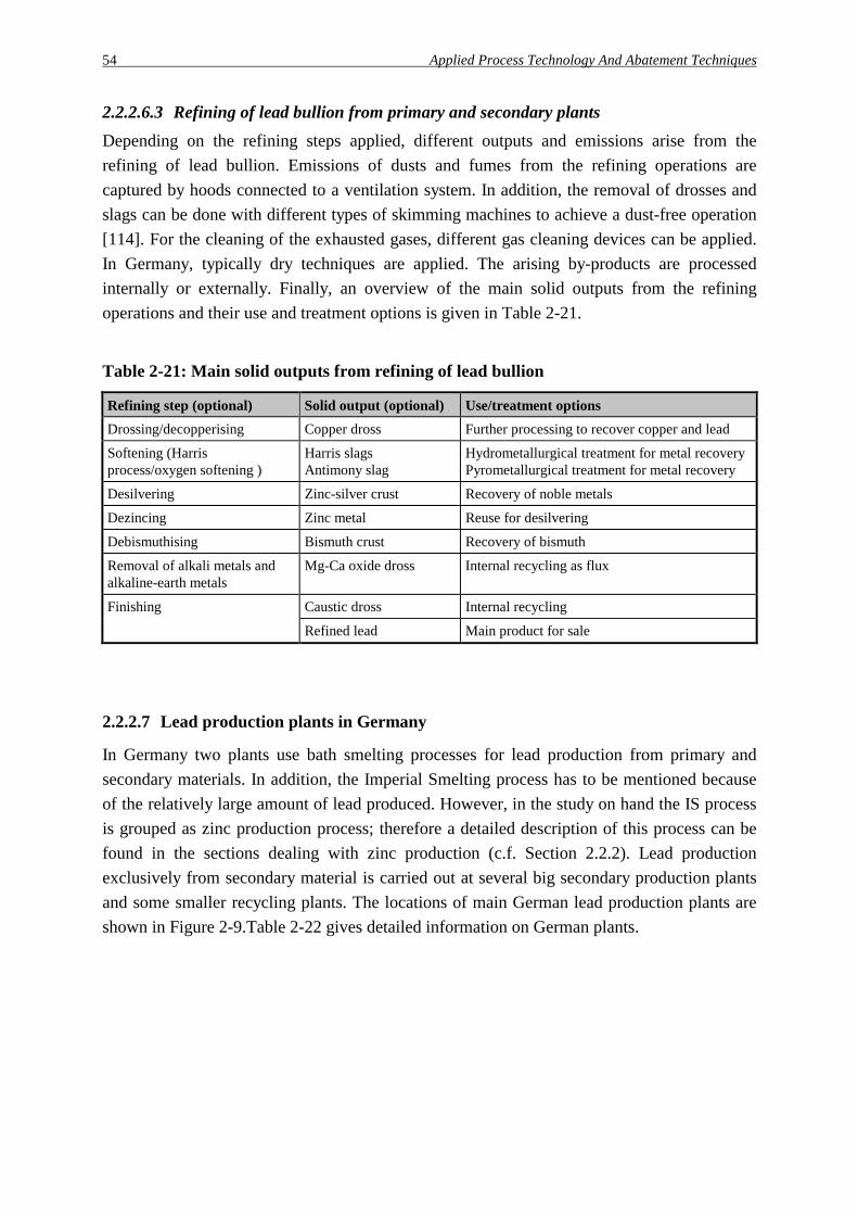
54 Applied Process Technology And Abatement Techniques
2.2.2.6.3 Refining of lead bullion from primary and secondary plants Depending on the refining steps applied, different outputs and emissions arise from the refining of lead bullion. Emissions of dusts and fumes from the refining operations are captured by hoods connected to a ventilation system. In addition, the removal of drosses and slags can be done with different types of skimming machines to achieve a dust-free operation [114]. For the cleaning of the exhausted gases, different gas cleaning devices can be applied. In Germany, typically dry techniques are applied. The arising by-products are processed internally or externally. Finally, an overview of the main solid outputs from the refining operations and their use and treatment options is given in Table 2-21.
Table 2-21: Main solid outputs from refining of lead bullion
Refining step (optional) Solid output (optional) Use/treatment options Drossing/decopperising Copper dross Further processing to recover copper and lead
Softening (Harris process/oxygen softening )
Harris slags Antimony slag
Hydrometallurgical treatment for metal recovery Pyrometallurgical treatment for metal recovery
Desilvering Zinc-silver crust Recovery of noble metals
Dezincing Zinc metal Reuse for desilvering
Debismuthising Bismuth crust Recovery of bismuth
Removal of alkali metals and alkaline-earth metals
Mg-Ca oxide dross Internal recycling as flux
Finishing Caustic dross Internal recycling
Refined lead Main product for sale
2.2.2.7 Lead production plants in Germany
In Germany two plants use bath smelting processes for lead production from primary and secondary materials. In addition, the Imperial Smelting process has to be mentioned because of the relatively large amount of lead produced. However, in the study on hand the IS process is grouped as zinc production process; therefore a detailed description of this process can be found in the sections dealing with zinc production (c.f. Section 2.2.2). Lead production exclusively from secondary material is carried out at several big secondary production plants and some smaller recycling plants. The locations of main German lead production plants are shown in Figure 2-9.Table 2-22 gives detailed information on German plants.

Applied Process Technology And Abatement Techniques 55
Nordenham
Duisburg
Freiberg
Goslar
Legend:
Braubach
Brilon
Rommerskirchen
Krautscheid
Lead production using primary / secondary raw materialsLead production exclusively from secondary raw materials
Stolberg
Nürnberg
Figure 2-9: Locations of lead production plants in Germany

Table 2-22: Lead production and recycling plants in Germany
"Berzelius" Stolberg GmbH
Metaleurop Weser Blei GmbH, Nordenham
Metallhütte M.I.M. Hüttenwerke, Duisburg
Muldenhütten Recycling und Umwelttechnik GmbH, Freiberg
VARTA Recycling GmbH, Krautscheid
BSB Recycling GmbH, Braubach **)
Bleihütte Oker, Harz-Metall GmbH, Goslar
Metallhütte Hoppecke GmbH & Co. KG, Brilon
Metallhütten-gesellschaft Schumacher, Rommersk.
Hetzel Metalle GmbH, Nürnberg
Process technology
QSL Sirosmelt Imperial Smelting Process
Engitec technology Short rotary furnaces
VARTA process (lead shaft furnace )
Engitec technology Short rotary furnaces
MA technology Short rotary furnace
Short rotary furnace
Short rotary furnace
Short rotary furnace
Special equipment
Waste incineration plant
Compoundation plant
Feed consump-tion [t/a] / composition
150,000 Lead concentrates: (60%) Lead residues: (40%) (Lead bullion)
130,000 Lead concentrates (45%)Lead residues (55%) (Lead bullion)
250,000 Lead concentrates (50%)Lead/zinc residues (50%)
55,000 Spent batteries Lead residues Scraps
55,000 Spent batteriesLead residues Scraps
55,000 Spent batteries Lead residues Scraps
75,000 Spent batteries, lead residues, scrap
12,000 Spent batteriesLead residuesScraps
18,000 Scraps (75%) Spent batteries (25%)
22,000 Scraps (80%); Spent batteries (20%)
Lead bullion production capacity*) [t/a]
90,000 90,000 45,000 100,000 zinc
40,000 35,000 35,000 25,000 10,000 15,000 18,000
Refined lead production capacity [t/a]
150,000 120,000 0 50,000 50,000 40,000 50,000 10,000 15,000 20,000
Main by-products
Sulphuric acid, Slag
Sulphuric acid, Slag
Sulphuric acid, Cadmium carbonate, Slag
Sodium sulphate, PP chips
Slag, Lead-iron matte, Lead dross
PP, Compounded PP chips, Paste
Paste Slag, Lead dross
Slag, Lead-iron matte, Lead dross
Slag
Certificates ISO 9002 ISO 9002 - ISO 9002 ISO 9001 EMAS ISO 14001
ISO 9002 ISO 9001 ISO 9002 EMAS (pilot trial) ISO 14001
ISO 9002 n. a. ISO 9002 ISO 9002
*) The nominal capacity is mostly larger than the above-mentioned values. **) BSB stands for the former name Blei- und Silberhütte Braubach.

Process Technology, Abatement Techniques And Present Consumption/Emission Levels 57
3 Process technology, abatement techniques and present con-sumption/emission levels in German zinc and lead production
3.1 Zinc production in Germany In the following, the main zinc production plants operated in Germany are presented in detail. Based on the general descriptions given in Chapter 2, the processes and techniques applied are described. In addition, present consumption and emission levels for each plant are given, where available. Due to the fact, that a strict distinction between primary and secondary process routes is not possible, in this chapter all main German production plants are included.
3.1.1 Hydrometallurgical zinc production plants in Germany
In Germany, there are two zinc electrolysis plants with an overall production capacity of about 235,000 tons zinc.
3.1.1.1 Zinc electrolysis plant Z1
3.1.1.1.1 General information The Company Z1 operates a zinc electrolysis plant with a capacity of 130,000 t zinc products.12 60,000 t/a zinc-aluminium and zinc-aluminium-lead alloys used for continuous galvanising and about 40,000 t/a zinc-aluminium-copper alloys for die casting and similar applications are the main products. The plant comprises the process units, raw materials handling, roasting furnace/sulphuric acid production, leaching plant, purification of solution, electrolysis plant, melting, alloying and casting of zinc products, cadmium plant, and a central water treatment plant. A schematic flowsheet of zinc electrolysis plant Z1 is given in Figure 3-1. The staff consists of about 260 employees in the production related units; about 240 employees work in the maintenance, transport, chemical laboratories, environment, and administration. Some input and output values are given in Table 3-1.
12 Process information, presented in this section, mainly base on company information given by company Z1
[58].

58 Process Technology, Abatement Techniques And Present Consumption/Emission Levels
Fluidised bed roaster
Zinc concentrates
Calcine
Purified zinc solution
Electrolyte
Cathode zinc
Melting, alloying, casting
Zinc (SHG Zinc 99,995)
Zinc alloys
Zinc dust
Spent electrolyte
Sulphuric acidLead-silver
by-product
Jarosite
Enriched copper by-product
Cadmium (> 99,995 %)
Electrolysis plant
Raw materials handling
Roast gas cleaning
Sulphuric acid plant
Leaching plant / treatment of leaching residues
Solution purification
Cadmium plant / cadmium refinery - enrichment Cd - residue- briquetting- vacuum distillation of Cd-residue
Off-gas
Figure 3-1: Zinc electrolysis plant Z1
Table 3-1: Input and output data for the zinc electrolysis plant Z1
Input [t/a] Output [t/a]
Sulphidic zinc concentrates 225,000 Zinc products 130,000
Electrical energy n. a. Lead/silver by-product 15,000
Sulphuric acid 225,000
High grade cadmium 400
Copper by-product 1,000
Jarosite (dry) 45,000
Calomel (wet) 6
Hg-Se sludge (wet) 30
Source: company information company Z1, 1998

Process Technology, Abatement Techniques And Present Consumption/Emission Levels 59
3.1.1.1.2 Description of the main process units and environmental techniques In the following, detailed information on main the environmental measures in the different process units are given. Besides technical data, input and output levels are presented, if available.
Raw materials handling Sulphidic zinc ore concentrates are the main feed material of the plant. A typical composition is shown in Table 3-2. Other zinc bearing materials like filter dusts, residues, ashes are processed to a minor extent only.
Table 3-2: Composition of zinc concentrate feed (main elements only)
Elements
Range [wt.-%]
Average [wt.-%]
Zn 46.7 - 61.9 55.0
Pb 1.0 - 3.2 2.0
Cu 0.03 - 1.03 0.26
Cd 0.14 - 0.48 0.21
Fe 1.6 - 12.0 5.6
S 30.1 - 37.3 31.7
Ag 0.006 - 0.04 0.0125
Source: company information company Z1, 1997
The main sources are Scandinavia, Irish and North American mines. The concentrates are shipped to the company's harbour, unloaded by crane and transported by covered conveyor belts (length 260 m) via a sampling and weighing station to the raw materials storage building with a capacity of up to 60,000 t. The different types of concentrates are stored in separate piles. Mixtures of concentrates are prepared inside the storage building by an overhead crane. The same crane is used to feed the mixed concentrates via covered conveyor belts to the day bin of the roasting furnace.
Fluidised bed roaster/roast gas cleaning/sulphuric acid plant The feed mixture is fed to the fluidised bed roaster (grate size 90 m2) by two feed belts. At temperatures of about 950°C, metal sulphides are converted into metal oxides and sulphur dioxide by oxygen out of the air blown into the furnace. The produced calcine is cooled, ground in a ball mill and pneumatically transported to two storage bins with a capacity of 5,000 t each, or directly to the intermediate bins of the leaching plant. Off-gases from the ball mill and the transport lines are cleaned in bag filters. In order to produce high pressure steam, the hot sulphur dioxide containing off-gas is cooled in a waste heat boiler. After dedusting in cyclones and hot electrostatic precipitators it is quenched down in a scrubber. For further purification and the removal of the remaining dust

60 Process Technology, Abatement Techniques And Present Consumption/Emission Levels
and volatile compounds (i.e. selenium and mercury compounds) the off-gas is passed through two wet electrostatic precipitators. In the next step, metallic mercury is removed by the Boliden/Norzink process, where saleable Calomel is formed. The cleaned gas is then converted in a double catalysis acid plant into high grade sulphuric acid as a marketable by-product. Multiple tube filters are applied to remove the remaining acid mist before the off-gas is led to the stack (height 125 m).
Leaching plant/treatment of leaching residues The leaching plant consists of five leaching steps including the Jarosite process. The calcine is leached in the first step (neutral leaching) consisting of four stirred reactors in series with spent electrolyte at a low acid concentration at temperatures of 90°C. Afterwards the neutral leaching solids and liquids are separated in a thickener. Besides zinc sulphate, the overflow solution contains compounds like copper-, cadmium-, cobalt- and nickel sulphates and has to be further purified. The underflow of the thickener still contains undissolved zinc compounds and is leached in the two following stages at a higher acid concentration and raised temperature. The pulp of the last stage is filtered on two belt filters. The solids contain lead and silver compounds and are sold as a lead-silver concentrate to a lead plant to recover the valuable metals. For the precipitation of dissolved iron from the filtrate, the Jarosite process is used. The iron is precipitated as ammonium jarosite (NH4[Fe3(SO4)2(OH)6]) by the addition of ammonia water and calcine to decrease the acid concentration. The ammonium jarosite is separated in thickeners and belt filters with a high efficiency to reduce the content of water soluble compounds (e.g. the content of water soluble cadmium compounds can be reduced to less than 170 ppm). Because of its composition it has to be stored as waste in a specially prepared pond. All reactors and filters of the leaching plant are connected to a central exhaust gas scrubbing system to prevent emissions of aerosols.
Solution purification The zinc sulphate solution produced in the leaching plant has to be cleaned of compounds prior to electrolysis to prevent any negative influence to the current efficiency (i.e. due to copper, cobalt, nickel, ...) or co-precipitation with zinc in the cellhouse (i.e. cadmium). For purification, the solution is heated in two hold up tanks (volume: 200 m3 each) up to 90°C and above and then fed to the first stage. Zinc dust and arsenic trioxide are added to precipitate copper, cobalt, nickel and other elements which are nobler than zinc. The precipitated fraction is separated in filter presses and treated to increase the copper content to approximately 60 %. This enriched copper by-product is sold to copper smelters. In a second step zinc dust is added to the filtered solution in order to remove the remaining elements like cadmium. The precipitated fraction is separated in filter presses and reprocessed in the hydrometallurgical cadmium plant to produce briquettes with a cadmium content of 98 % and above. The filtered zinc sulphate solution with its high purity is passed as raw

Process Technology, Abatement Techniques And Present Consumption/Emission Levels 61
material for the electrolysis process. The exhaust gas from all reactors with the risk of arsine formation is treated in an exhaust gas washing facility with a strong oxidative medium to remove arsine but also other metal compounds. The remaining reactors of the solution purification, the cadmium plant and the copper residue treatment are connected to a scrubber to prevent emission of i.e. metal compounds.
Electrolysis plant (cellhouse) The zinc sulphate solution is cooled in cooling towers, mixed with spent electrolyte and fed to the cellhouse at a temperature of about 32°C. Metallic zinc is deposited on the aluminium cathodes and stripped automatically once a day with mechanical stripping machines. The exhaust air from the cooling towers is further purified in a three stage mist collector.
Melting, alloying and casting The cathode zinc is melted in an induction furnace and cast with automatic casting machines. Most of the zinc produced is alloyed with aluminium, copper, magnesium or lead to produce zinc alloys for galvanising or die casting purposes. Arising drosses are recycled to the fluidised bed roaster after separation of the metallic fraction. All furnaces are connected to a central bag filter to prevent dust emissions.
Cadmium plant/cadmium refinery The cadmium briquettes from the hydrometallurgical cadmium plant are melted. The liquid cadmium is distilled under vacuum to produce high grade cadmium which is cast in ingots. The exhaust gas from the furnaces, the distillation column and the casting section is treated in two electrostatic precipitators in parallel to prevent cadmium emissions.
Central water treatment plant All rainwater is collected in a special basin on site and used internally. Contaminated waste water, mainly from the roast gas cleaning unit is treated in a three stage water treatment plant in combination with the waste water from the neighbouring lead plant. Sodium sulphide and sodium hydroxide are used as precipitating agents, iron sulphate as a flocculant in the last stage. The solid residue is partly reused in the lead plant, the remaining part is stored in a public pond for hazardous waste.

62 Process Technology, Abatement Techniques And Present Consumption/Emission Levels
3.1.1.1.3 Summarised data on outputs and environmental concerns Table 3-3 shows the main controlled emissions into the air from the zinc electrolysis plant Z1.
Table 3-3: Controlled emissions into the air from the zinc electrolysis plant Z1 (1994)
Flow Main components [kg/a] Process unit [Nm³/h] Dust Zn Cd SO2 Sulphuric acid plant 59,400 - - - 402,762
Transport/grinding of calcine 22,000 86 46.7 0.19 -
Leaching plant 34,600 - 122.1 2.32 -
Solution purification/hydro-metallurgical cadmium plant
31,100 - 49.2 3.44 -
Cooling towers (electrolysis plant) 1,664,300 - 533.2 - -
Melting, alloying casting (incl. Zinc dust production)
38,100 888.8 550.6 0.06 -
Cadmium refinery 9,200 7.1 1.1 2.72 -
Source: company information company Z1, 1995
The wet cleaning of the roast gas is the only production related source of waste water in the electrolysis plant. Together with the waste water from the neighboured lead production plant, the waste water is treated in one central treatment plant. Data on discharged water from both plants is given in Table 3-4.
Table 3-4: Waste water from the zinc electrolysis plant Z1
Treatment Flow Main components [mg/l] Process unit [m³/h] Zn Pb Cd Central waste water plant Discharge 45 - 50 0.01 - 0.2 0.01 - 0.09 0.001 - 0.01
Source: company information company Z1, 1998
Data on arising solid by-products and residues as well as treatment options are summarised in Table 3-5.

Process Technology, Abatement Techniques And Present Consumption/Emission Levels 63
Table 3-5: By-products and residues from the zinc electrolysis plant Z1
Process unit
By-products/residues Amount [t/a]
Use/treatment option
Roast gas cleaning Calomel 6 Sale product
Mercury-selen residue 30 Dumping
Leaching plant/treatment of leaching residues
Lead-silver concentrate 15,000 Lead production plant
Jarosite 45,000 Dumping
Solution purification/hydro-metallurgical cadmium plant
Cadmium Copper by-product
400 1,000
Sale product Copper production plant
Waste water treatment plant Sludges 200 Dumping
Source: company information company Z1, 1998
3.1.1.2 Zinc electrolysis plant Z2
3.1.1.2.1 General information The company Z2 operates a zinc electrolysis plant with an annual capacity of 105,000 t of electrolytic zinc and comprises the process units: raw materials handling, roasting furnace/sulphuric acid production, leaching plant, purification of solution, cadmium plant, electrolysis plant, melting, and casting of zinc products and a central water treatment plant. Some input and output values are given in Table 3-6. A schematic flowsheet of the zinc electrolysis plant (company Z2) is given in Figure 3-2.
Table 3-6: Input and output values of the zinc electrolysis plant Z2
Input [t/a] Output [t/a]
Sulphidic zinc concentrates 170,000 Zinc products 105,000
Zinc bearing materials 40,000 Leaching residue 50,000
Electrical energy n. a. Sulphuric acid 160,000
High grade cadmium n. a.
Copper by-products n. a.
Source: company information company Z2, 1998

64 Process Technology, Abatement Techniques And Present Consumption/Emission Levels
Fluidised bed roaster
Solution purification
Electrolysis plant(cellhouse)
Melting / Casting
Cadmium plant / cadmium refinery
Zinc ingots
Roast gas cleaning
Leaching plant (liquid - solid separation)
Raw materials storage / handling
Sulphuric acid plant
Leaching residue (to ISP plant / waelz kiln)
Cadmium sheets
Sulphuric acid
Zinc concentrates (ZnS), zinc-bearing materials (leached waelz oxide, flue dusts, ...)
ZnO
Waelzoxide
Spent acid
Off-gas
Figure 3-2: Zinc electrolysis plant Z2
3.1.1.2.2 Description of the main process units and environmental techniques In the following, detailed information on the main environmental measures in the different process units are given. Besides technical data, input and output levels are presented, as far as available.
Raw materials handling Sulphidic zinc ore concentrates are the main feed material of the plant. The main sources are mines in Europe and Canada, but also in Middle- and South-America and Australia. The concentrates are shipped to the company's harbour, unloaded by a crane and transported by covered conveyor belts via a sampling and weighing station to the raw materials storage. Beside concentrates, other zinc-bearing materials like ashes, filter dusts and leached waeltz oxide are processed to a smaller degree.

Process Technology, Abatement Techniques And Present Consumption/Emission Levels 65
Fluidised bed roaster/roast gas cleaning/sulphuric acid plant The mixture is charged into each of the two fluidised bed roasters (grate size 55 m2) via a rotary feed table. At a constant furnace temperature, the conversion of metal sulphides takes place and a roast gas with 12 vol.-% sulphur dioxide is obtained.
Table 3-7: Chemical composition of calcine (example)
Component [wt.-%] Component [wt.-%]
Zn 55 - 65 As 0.03 - 0.06
Fe 6 - 9 Tl 0.01 - 0.02
S (SO42-) 2 - 3 Bi 0.01 - 0.03
Cd 0.15 - 0.3 Silicic acid 1 - 2.5
Pb 1.5 - 3.0 Lime 0.5 - 2
Cu 0.3 - 1.0 Mg 0.3 - 0.5
Co 0.03 - 0.08 Al2O3 0.3 - 0.6
Ni 0.03 - 0.08
Source: Wiegand [111]
The calcine is precipitated in the different gas treatment units and together with the calcine discharged from the roaster subsequently cooled down to 150°C, ground and pneumatically transported to four storage bins of the leaching plant. A schematic view of the whole roast gas cleaning unit is shown in Figure 3-3. The heat recovered from calcine cooling in the cooler is used internally. In order to recover the roast gas heat, the hot sulphur oxide containing off-gas is cooled down to 350°C in a waste heat boiler. After pre-dedusting in two hot cyclone groups, it is cleaned in three hot electrostatic precipitators. For further cleaning and cooling, six Venturi scrubbers in parallel and several gas coolers are used. Subsequently the off-gas is cleaned in wet ESPs and the mercury removal plant (Boliden/Norzink process) and then dried in an air dryer. After mercury removal using the Boliden/Norzink process the purified off-gas is passed to the sulphuric acid plant. The acid plant consists of two production lines with a sulphuric acid capacity (96 %) of 700 t/d and 265 t/d respectively. The production of sulphuric acid with a 98 % quality is also possible. As a consequence of a research project, several technical measures have been realised in order to reduce the fugitive dust emissions during the start-up phase of the roaster and during the operation of the calcine preparation and transport equipment13. With the installation of a suction ventilation system dust emissions from the calcine coolers, the ballmill, and the start-up phase of the roaster can be collected together with the exhausted ambient air from the roaster shop. The two stage filter system consists of a bag filter followed by a non-dedustable high efficiency sub-micron particulate air filter. A 13 A detailed description of the project The reduction of diffuse heavy metal emissions in a roasting plant
using process and separation technologies as well as through reduction of uncontrolled thermal air currents is given by Wiegand [111].

66 Process Technology, Abatement Techniques And Present Consumption/Emission Levels
clean gas dust content of less than 1 mg/Nm³ for the general operation can be achieved. Fugitive dust emissions from the roasters have been reduced by a complete enclosure. To reduce thermal air currents, the chutes of the waste heat boiler are lined with refractory bricks in the dust removal area and also partly insulated.
Zinc blende
Air
Fluidised bed roaster Waste heat
boiler
Steam
Hot ESP
Venturi scrubber
CoolerWet ESP
Air
Weak acid (to waste water treatment plant)
Air dryer
Mainblower
Converter
Intermediateabsorber
Finalabsorber
To stack
Produced sulphuric acid
Cooler
Ballmill
Fullerpump
Calcine to leaching plant
Intermediateheat
exchanger
Sulphuric acid plantCalcine
Cyclone
Gas / gasheat
exchanger
Boliden-Norzinkprocess
Figure 3-3: Roast gas cleaning system of a fluidised bed roaster
Source: according to Wiegand [111]
Table 3-8 gives some examples of results to show the reduction of total dust emissions achieved by the installation of several reduction measures. The measurements were taken before and after the plant modernisation [111].

Process Technology, Abatement Techniques And Present Consumption/Emission Levels 67
Table 3-8: Reduction of total dust emissions from a fluidised bed roaster
Old installation*) (1987) New installation*) (1992)
Measures Fugitive emissions occur during repair operations and by thermal air currents:
- no further emission reduction were installed
The following emission reduction measures have been installed:
- suction ventilation system - two stage filter system - insulation of waste heat boilers - complete enclosure of the roaster
Total dust emissions [kg/a]
3,350 1,757
Zinc content in dust [kg/a]
1,561 906
Lead content in dust [kg/a]
56 101 (higher value due to a higher lead content in the raw dust)
Cadmium content in dust [kg/a]
9.5 8.2 (high value due to a higher cadmium content in the raw dust)
*) Zinc production capacity: 135,000 t/a
Source: Wiegand [111], Rentz et al. [71]
Leaching plant/treatment of leaching residues The calcine is leached in the one-stage leaching plant, the so-called neutral leaching. Mainly zinc, copper and cadmium are dissolved. After the neutral leaching, the solids and liquids are separated in a thickener. The solid residue is de-watered and washed in a filter drum first and then in a filter press and centrifuges. The remaining iron and zinc containing filter cake with a moisture of 17 - 25 % further has to be treated externally. At present the filter cake is processed in a pyrometallurgical IS furnace plant and in waelz kilns.
Solution purification The zinc sulphate solution produced in the leaching plant is cleaned in a three stage purification unit. In the first stage the solution is heated up to 90°C, and impurities like copper, nickel, arsenic, etc. are precipitated by the addition of zinc dust and arsenic compounds. The residue is separated with filter presses, washed, filtered again, and stored for sale. The filtered solution is cooled in a heat-exchanger and fed into fluidised bed reactors (Outokumpu process). Zinc dust is added to the filtered solution in order to remove elements like cadmium and thallium by cementation. The cementated fraction is separated by filter presses, mashed and passed to the cadmium plant for further processing. For the final purification again zinc dust is added in the third stage. The purified solution is cooled in cooling towers and passed to the cellhouse.

68 Process Technology, Abatement Techniques And Present Consumption/Emission Levels
Electrolysis plant (cellhouse) The cellhouse contains 106 electrolysis cells with 85 anodes and 84 cathodes per cell. The cathode area is 3.5 m². The zinc sulphate solution is mixed with spent electrolyte and fed to the cells. Metallic zinc is formed on the aluminium cathodes and stripped automatically every 24 hours with mechanical stripping machines. Parts of the cell acids are used in the leaching plant. The whole cellhouse is exhausted, the exhaust air is passed to a mist collector.
Melting and casting After drying the cathode zinc is melted in two induction furnaces (total smelting capacity 32 t/h) and tapped in runners. For ingots (1.5 t or 6 t) a special casting machine is used. The off-gases from the furnaces are sucked off at the skimming area and cleaned in bag filters.
Cadmium plant/cadmium refinery The cementated cadmium is leached, precipitated by the addition of zinc dust and concentrated as a sponge. The cadmium sponge is leached. The solution is purified in several steps and a thallium compound can be separated in a filter press. Metallic cadmium is recovered by electrolysis from internal and external residues. The cellhouse contains 15 electrolysis cells with 40 aluminium cathodes and 41 lead anodes each. The electrolysis is operated with a current density between 50 and 100 A/m². The produced cadmium sheets are sold in different shapes e.g. for further processing. All tanks and vessels are covered. The ventilation system is operated with a slight negative pressure. The exhaust air is cleaned in the central wet scrubber system.
Central water treatment plant All process effluents are treated together with the rainwater in the central waste water treatment plant.

Process Technology, Abatement Techniques And Present Consumption/Emission Levels 69
3.1.1.2.3 Summarised data on outputs and environmental concerns Table 3-9 shows the main controlled emissions into the air from the zinc electrolysis plant Z2.
Table 3-9: Controlled emissions into the air from the electrolysis plant Z2
Flow Main components [kg/a] Process unit [Nm³/h] Dust Zn Cd SO2 Sulphuric acid plant 35,000 - 40,000 - - - 250,000 - 300,000
Transport/grinding of calcine 12,000 - 15,000 70 - 90 50 - 60 < 0.2 -
Leaching plant (incl. solution purification and cadmium refinery)
70,000 - 80,000 - 20 - 25 1 - 2 -
Cooling towers (electrolysis plant) 800,000 - 900,000 - 800 - 900 - -
Melting, alloying and casting 60,000 - 70,000 200 - 240 130 - 170 - -
Source: company information company Z2, 1998
In Table 3-10 the waste water and process water from the different process units are summarised.
Table 3-10: Waste water from the zinc electrolysis plant Z2
Treatment Flow Main components [mg/l] Process unit [m³/h] Zn Pb Cd Central water treatment plant Discharge 30 - 45 0.1 - 0.8 0.1 - 0.3 0.01 - 0.08
Source: company information company Z2, 1998
Data on the solid by-products and residues are shown in Table 3-11.
Table 3-11: By-products and residues from the zinc electrolysis plant Z2
By-product/residue Amount Use/treatment option Process unit [t/a] Leaching plant Lead-silver concentrate n. a. Lead production plant
Zinc-iron intermediate 50,000 Zinc production plant
Solution purification Metallic cementate n. a. Copper production plant
Electrolysis plant Sludge n. a. Internal treatment
Central water treatment plant Gypsum n. a. Cement production plant
Source: company information company Z2, 1998

70 Process Technology, Abatement Techniques And Present Consumption/Emission Levels
3.1.2 Pyrometallurgical zinc production in Germany
3.1.2.1 Imperial Smelting Process (ISP) plant Z3
3.1.2.1.1 General information The company Z3 runs an ISP plant, which comprises the process units: raw materials handling, sinter plant, hot briquetting plant, IS furnace, refining plant, a sulphuric acid plant and a cadmium plant. A schematic view of the plant is given in Figure 3-4.
Sinter plant Hot briquetting
plantDirekt injection
(EAF dust)
IS-furnace
Hot briquetts
SinterRoast gas
Sulphuric acidplant
Cadmium plant
Refining plant
IS-furnace raw zinc Secondary zinc
Dust
Sulphuric acid (96 % H2SO4.)
Cadmium-zinccarbonat e
IS-furnace Slag
Lead bullion
Refined zinc (-SHG 99,995% -GOB 98,55%)
Zinc-cadmium alloys
Top gas cleaning
Off-gas
Roast gas cleaning
Prozess gas
Raw materials handling
Figure 3-4: Imperial Smelting plant by company Z3
The ISP plant, erected in 1965, produces on average about 100,000 tons of zinc, about 35,000 tons of lead bullion and about 125,000 tons of sulphuric acid per year (1996). Therefore about 250,000 t of input materials are processed (c.f. Table 3-12). At present, the ratio between primary and secondary raw materials is about 1:1.

Process Technology, Abatement Techniques And Present Consumption/Emission Levels 71
Table 3-12: Input and output data of the ISP plant operated by company Z3
Input [t/a] Output [t/a]
Primary raw materials 125,000 Zinc 100,000
Secondary raw materials 125,000 Lead bullion 35,000
Coke 100,000 Sulphuric acid 125,000
IS furnace slag 70,000
Cadmium carbonate n. a.
Source: company information company Z3, 1998
3.1.2.1.2 Description of the main process units and environmental techniques In the following detailed information on the main environmental measures in the different plant units are given. Besides technical data, input and output levels are presented, if available.
Raw materials handling For the raw materials preparation, the common units sinter plant and hot briquetting plant are operated. Recently, company Z3 has put a technology into use, that makes it possible to inject zinc containing dust directly into the furnace, without the need to treat the dust by the waelz-process and hot briquetting. With this process 10,000 tons per year EAF dust are used, at the moment. company Z3 plans to expand the dust injection by 35,000 to 40,000 t/a within the near future. Consequently, in the company Z3 plant three different alternatives exist for raw materials preparation as shown in Figure 3-4 and Table 3-13.
Table 3-13: Preparation of raw materials for the ISP Plant
Process unit Raw materials Sinter plant Ore concentrates (Zn, Pb, Cu, Cd, ...)
Sulphur containing materials Sludges/residues from water treatment plants Halogen-containing residues
Hot briquetting plant Ashes and drosses Oxidic raw materials (dry/wet) like waelz oxide, filter dusts Refining residues, ...
Direct injection Dry and fine materials with zinc, zinc/lead, or lead/copper metal content
Source: Schneider/Schwab [79]
To demonstrate the flexibility of the ISP concerning raw materials, an overview on secondary raw materials processed in the company Z3 plant is given in [79]. The requirements for the chemical composition of the main components can be given only as rough estimates: zinc (15 - 70 %), lead (0 - 70 %), cadmium (0 - 2 %), alkali metals (0 - 10 %), and chlorides (0 - 10 %). In the end, the putting together of the different raw materials is decisive for the

72 Process Technology, Abatement Techniques And Present Consumption/Emission Levels
preparation of a suitable input charge. Typical secondary raw materials are shown in Table 3-14.
Table 3-14: Secondary raw materials for the ISP plant (examples)
Raw materials Components [wt.-%]
Filter cake cupola
Filter cakecupola
Cupola dust
EAF dust
Lead dust
Zinc-lead oxide
Zinc-iron intermediate
Zn 31 25 31 23 2 44 18
Pb 3 3 0.1 1.3 68 15 7
Cu 0.2 0.1 - 0.1 - 0.4 1.6
C 11 16 5 2 2 0.6 0.2
FeO 10 8 23 35 5 4 33
MnO 2 4 0.6 4 3 0.5 0.5
CaO 2.5 1.5 3 8 3 1.4 2
Al2O3 2.5 2 2.7 0.7 0.3 0.6 2
SiO2 15 13 13 1 - 1 3
Na2O 1.8 1 0.6 0.6 0.5 1 0.2
K2O 1.0 1.7 0.7 1.0 0.2 2 0.3
Cl 0.4 0.7 0.5 0.6 0.2 4 -
H2O 45 26 0.4 10.6 10.4 1.8 30
Source: Schneider/Schwab [79]
Sinter plant The sintering belt has a length of 36 m and a width of 2 m. The layer of raw materials is approx. 30 cm thick. A sinter hood is installed to capture off-gases which are led to the roast gas cleaning. At the end of the line the sinter is cooled down, broken and screened. Off-gases from sinter cooling and breaking are dedusted in fabric filters. Sinter fines from screening are recycled to the sinter mixture.
Roast gas cleaning The exhaust off-gases from the sinter plant with a temperature of about 300°C are led to a hot ESP. After first dedusting, the off-gases are further cleaned and cooled in wet scrubbers. The Norzink/Boliden mercury removal process is used to reduce the mercury content in the off-gas. For final dedusting, the gas is led in a wet ESP. In the last step the gas is dried with sulphuric acid and fed into the sulphuric acid plant. The sulphur dioxide content is about 5 - 6 vol.-%.
Sulphuric acid plant The sulphuric acid plants consists of two double contact plants for the conversion of sulphur dioxide into sulphuric acid.

Process Technology, Abatement Techniques And Present Consumption/Emission Levels 73
Cadmium plant The cadmium containing dust from the roast gas cleaning is leached with sulphuric acid for cadmium recovery. The lead containing residue is recycled to the sinter plant. Dissolved cadmium is precipitated with soda and separated by filtration as zinc-cadmium carbonate. After thallium separation, the filtrate is passed to the central water treatment station.
Hot briquetting plant Finer raw materials (< 10 mm), mainly sulphur free, oxidic materials have to be agglomerated before they are fed into the furnace. Together with fine dusts, these substances are homogenised in a mixer and pelletized on a pelletising disc (diameter: 3 m) by the addition of water. The green pellets produced are heated in a rotary furnace and passed to the roll briquetting press. After briquetting and cooling they can be charged to the IS furnace. The off-gases from the hot briquetting plant are dedusted in a fabric filter and afterwards cleaned in an activated coke filter to achieve PCDD/PCDF clean gas concentrations of less than 0.1 ng-TE/Nm³. The loaded coke is finally injected into the IS furnace through tuyères.
IS Furnace The input materials (sinter and briquettes) are charged together with preheated coke in layers through a double bell at the top of the furnace. Preheated air, so-called hot wind with a temperature of about 1,100°C, is blown from below into the shaft furnace using 16 tuyères. For furnace operation the use of up to 45,000 Nm³/h is possible. Three cowpers are operated for air preheating. To prevent emissions from charging, the furnace top is equipped with a double bell. Metal containing dust is injected through the tuyères of the furnace to produce metal in the most direct way, this technique is shown in Figure 3-5. Due to the high temperatures on the tuyère level of about 2,000°C, organic compounds like PCDD/PCDF possibly contained in the dust and carbon products, are destroyed. In order to prevent a re-oxidation of zinc vapour, hot air is injected into the top of the furnace. With partly post combustion of carbon monoxide the temperature at the top of the furnace is kept high. Covered fugitive emissions from the top furnace area are cleaned in a wet ESP. Lead bullion and slag are tapped at the bottom of the furnace and separate by gravity in a forehearth. Lead bullion is sold for further refining to lead refineries. The liquid slag is granulated with high-pressure water and slag granulates with a grain size of about 6 mm are obtained. For proper furnace operation, the slag composition has to be carefully controlled. A typical composition is shown in Table 3-15.

74 Process Technology, Abatement Techniques And Present Consumption/Emission Levels
Table 3-15: Typical composition of IS furnace slag
Component Fe2O3 Zn Pb CaO SiO2 Na2O K2O [wt.-%] 55 7.0 0.7 16.0 18.0 0.9 0.7
Source: company information company Z3, 1998
Eluate values of the granulated IS furnace slag are shown in Table 3-16. After granulation, the IS slag (70,000 tons slag per year) is used for road construction.
Table 3-16: Eluate values of granulated IS furnace slag
Criteria
Eluate (according to DEVS4)*)
[mg/l] Zn 0.02 - 0.1
Pb 0.005 - 0.1
As 0.001 - 0.02
Fe 0.05 - 0.2
Cu < 0.001 - 0.05
pH 7 - 11 *) DEVS4: Leaching test according to German DIN 38 414
Source: company information company Z3, 1998
Spray condenser and zinc/lead separator Zinc is transported with the off-gas at over 1,000°C into the spray condenser, where it is absorbed in a spray of molten lead generated by immersed rotors. Zinc containing condenser lead is pumped from the condenser into the cooling launder, where the liquid zinc is separated by cooling.
IS process gas cleaning The raw process gas released through the spray condenser outlet is dedusted in a desintegrator. The zinc and lead bearing sludges are recycled to the sinter plant feed. The clean gas values achieved are given in Table 3-17. After cleaning, the process gas is used for coke and wind preheating.

Process Technology, Abatement Techniques And Present Consumption/Emission Levels 75
Dust Dust DustCoke
Silo-truckDelivery / unloading
Balance
Mixer
Sieve
IS-furnace
(16 tuyères, 35,000 t/a)
Injectiontank
Sluice
Figure 3-5: Direct injection of zinc-containing dust
Source: Schneider/Schwab [79]
Refining Plant Zinc obtained at the IS furnace is sent to a thermal zinc refining process named after the New Jersey Zinc Co. In this process, refining is performed by rectification in indirectly heated refractory distillation columns made of silicon carbide. The whole system consists of 6 distillation columns. Besides shaft furnace raw zinc, other zinc qualities like remelted zinc are processed. For liquation and proportioning, different furnaces are operated in the refining plant. A schematic view of a crude zinc and cadmium refining plant is given in Figure 3-6 [30]. Products of the refining plant are Special High Grade zinc, cadmium free GOB zinc and a cadmium-zinc alloy. Different techniques for the reduction of heavy metal emissions from the zinc refinery were investigated in a research project carried out between 1985 and 198914. As a result a bag filter was installed for the cleaning of the zinc oxide containing waste gas from the heating
14 A detailed description of the project Reduction of heavy metal emissions of a zinc refinery by process- and
filter-technologies inclusive energy-removal using a waste heat boiler is given by Kola/Steil [44].

76 Process Technology, Abatement Techniques And Present Consumption/Emission Levels
chambers and the proportioning and liquation furnaces (about 35,000 Nm³/h). The dust content in the raw gas (450 mg/Nm³) is reduced to less than 5 mg/Nm³ in the clean gas. Before cleaning, the waste gas with a temperature of about 400°C is cooled in a waste heat boiler and steam is produced.
Crude zinc
1st stage distillation
Liquation / sodium treatment
Cadmium-freezinc
Zinc(GOB grade)
Drossto ISF
Leadto ISF
Condenser
Zinc-cadmiumalloy
2nd stage distillation
Zinc(SHG Grade)
VapourCondenser
Cadmium-zincalloy
Zinc and cadmium vapour
Figure 3-6: New Jersey process for the refining of crude zinc and cadmium
Water management/waste water treatment The ISP plant has a combined waste water system for the treatment of the process water, the cooling water and the surface water. A central waste water treatment plant is operated with two treatment units in parallel, each with a sufficient capacity for the whole waste water flow.
3.1.2.1.3 Summarised data on outputs and environmental concerns Table 3-17 shows the main controlled emissions into the air from the ISP plant. The main emission sources are monitored continuously. In addition, the measurement equipment of five sources has an on-line connection to the local environmental authority for direct access to emission values. 15
15 the so-called EFÜ (Emissionsdatenfern-Überwachung)-System

Process Technology, Abatement Techniques And Present Consumption/Emission Levels 77
Table 3-17: Controlled emissions into the air from the ISP plant
Flow Main components [mg/Nm³] Process unit [Nm³/h] Dust Zn Pb Cd SO2 Charging 90,000 2 - 10 1 - 5 0.5 - 2 0.01 - 0.1 -
Sinter plant 120,000 2 - 20 0.3 - 10 0.1 - 5 0.003 - 0.1 -
Hot briquetting 45,000 < 1 < 1 < 1 < 0.01 -
Sulphuric acid plant 54,000 - - - - 500 - 800
IS furnace 100,000 1 - 5 0.55 - 2.7 0.1 - 0.5 0.001 - 0.005 -
Secondary dedusting (IS furnace/refinery)
200,000 0.4 - 0.6 0.17 - 0.26 0.01 0.001 -
Refining plant 35,000 1 - 5 0.5 - 3 0.05 - 2 0.002 - 0.008 -
Slag treatment 50,000 3 - 18 2 - 10 0.4 - 3 0.008 - 0.02 -
Source: company information company Z3, 1998
In Table 3-18 data on waste water discharged from the ISP plant is summarised.
Table 3-18: Waste water from the ISP plant
Treatment Flow Main components [mg/l] Process unit [m³/h] Zn Pb Cd As Central water treatment plant Discharge 380 - 420 0.05 -1.0 0.05 - 0.5 0.005 - 0.035 0.005 - 0.1
Source: company information company Z3, 1998
Data on the different by-products and residues are shown in Table 3-19.
Table 3-19: By-products and residues from the ISP plant
By-product/residue Amount Use/treatment option Process unit [t/a] IS furnace Lead bullion 35,000 Sale product
(to lead industry for refining)
Sulphuric acid plant Sulphuric acid 125,000 Sale product
Sinter plant (roast gas cleaning) Calomel 15 Dumping
Wet ESP sludge 25 Dumping
Slag treatment IS furnace slag 70,000 Road construction
Speiss 85 Dumping
Cadmium plant Thallium sulphide 25 Dumping
Source: company information company Z3, 1998

78 Process Technology, Abatement Techniques And Present Consumption/Emission Levels
3.1.2.2 Waelz plants operated in Germany (plants Z4, Z5, Z7)
3.1.2.2.1 General information Among the high temperature zinc recovery processes, the treatment in a rotary kiln using the waelz technology is the most common in Germany, at the moment. This process, mainly used for the treatment of EAF carbon steel dust but also for retort residues in Germany, recovers zinc as so-called waelz oxide with a share of about 50 - 60 % of zinc and 7 - 13 % of lead. The required percentage of zinc, for example in EAF dust, so that the waelz process is economically viable, is at least 17 - 18 %. Figure 3-7 gives a schematic overview of a waelz plant [73].
Stack
Exhaustfan
Gas cooling
Rotary kiln
Coke, fluxesEAF-dusts
Water basin
Waelz slag
Waelz oxide
Air(Oil, gas)
Filter
Figure 3-7: Schematic view of a waelz plant The waelz oxide produced is sold to zinc smelters and serves as an important resource in the non-ferrous metal industry. The waelz process can be operated with basic or acidic slag treatment. Slag basicity (ratio of (CaO + MgO)/SiO2) has to be controlled below 0.5, which means acidic slag or above 2, which means basic slag. To adapt the correct slag basicity, silica or lime-containing materials are mixed with the raw materials. In Germany, three plants exist for treating EAF dusts, that employ the waelz technology.
Waelz plants Z4 and Z5 Company Z4 operates a waelz kiln with the acidic slag route, whereas the company Z5 uses the basic slag route. Technical data on the waelz kiln operation at plant z4 and Z5 are summarised in Table 3-20.

Process Technology, Abatement Techniques And Present Consumption/Emission Levels 79
Table 3-20: Technical data on German waelz plants Z4 and Z5
Plant Z4 Plant Z5 Treatment capacity for zinc residues [t/a] 60,000 40,000
Total feeding rate*) [t/h] 13 9
Production of waelz oxide [t/a] 22,000 13,000
Zinc metal content [t/a] 12,000 9,000
Employment 47 52 *) This value comprises also fluxes and coke.
Source: company information, company Z4/Z5, 1997
Table 3-21 shows input and output data of the waelz plant operated by company Z4.
Table 3-21: Main input and output data of the waelz plant Z4
Input Output EAF dust t/a 60,000 Waelz oxide t/a 22,000
Coke breeze t/a 22,000 Slag t/a 45,000
Sand, fluxes t/a 14,000
Electrical energy MWh/a 6,000
Source: Hoffmann [31], company information company Z4, 1998
Waelz plant operated by company Z7 The company Z7 operates a rotary kiln for processing of zinc-bearing materials. This plant uses the acidic slag route with a slag basicity of 0.3 - 0.4. Technical data on the waelz plant are summarised in Table 3-22. A schematic view of this plant is given in Figure 3-8.
Table 3-22: Technical data on the waelz plant Z7 (1996/97)
Plant Z7 Treatment capacity for zinc residues [t/a] 65,000
Total feeding rate*) [t/h] 9
Production of waelz oxide [t/a] 18,000
Zinc metal content [t/a] 9,500
Feeding time [h/a]/operation days [d/a] 7,150/318
Employment 36 **) *) This value comprises also fluxes and coke. **) At this location, company Z7 operates also a secondary lead production plant. The total employment is 140.
Source: company information, company Z7, 1998

80 Process Technology, Abatement Techniques And Present Consumption/Emission Levels
Coke breeze
Waelz slag
Dry waelz oxide (to moistening)
Waelz oxide separation
Process air
Raw gasProduced slag
EAF dustRetort residue
Bag filterDust settling
SilicaSweepings, rubble
Quenche Intermediate storage
Waelz kiln
Clean gas
Water
Dust (returned to kiln) Water
Quenche
Lime
Figure 3-8: Waelz plant Z7
Table 3-23 shows the input and output levels of the waelz plant operated by company Z7. A peculiarity of this plant is the usage of retort residues as feed material. The chemical composition of the retort residue processed is given in Table 3-25. In average, the input charge has a zinc content of 16 % and a lead content of 4 %. The waelz oxide is sold for the recovery of lead and zinc. The main customer is a zinc smelting plant owned by company Z1, of which company Z7 is also a 100 % subsiadiary.
Table 3-23: Input and output data of the waelz plant Z7 (1996/97)
Input [t/a] Output [t/a]
Retort residue, dry 27,700 Waelz oxide 17,000
Zinc carrier, dry (EAF dust, ...) 33,700 Slag 48,200
Coke breeze 10,800 Clean gas [Nm³/h] 70,000 - 90,000
Silica 7,500
Sweepings, rubble 2,100
Air [Nm³/h] 5, 000 - 10,000
Lime 1,000
Electrical energy [MWh/a] 4,620
Natural gas [Nm³/a] 92,000
Source: company information company Z7, 1998

Process Technology, Abatement Techniques And Present Consumption/Emission Levels 81
3.1.2.2.2 Description of the main process units and environmental techniques In the following, detailed information on the main environmental measures in the different plant units are given. Besides technical data, input and output levels are presented, if available.
Raw materials The main feed material for the waelz process are electric arc furnace dusts from the steel production industry with a share of about 80 %. In general, these dusts are already pelletized at the EAF plants and delivered as pellets to the waelz plant. The waelz technology makes it possible to treat a wide range of materials to recycle zinc and other heavy metals. For example, the retort residues with their low zinc content are mixed with EAF dusts to prepare a input mixture with a sufficient zinc content (plant Z7). The physical aspects of input materials and the conditions for feeding the furnace are not very strict. Nevertheless agglomeration or moisturing is needed. Small amounts of non-pelletized or moistured materials can be accepted. A list of raw materials used in the waelz process is shown in Table 3-24, typical compositions of the main feed materials are given in Table 3-25.
Table 3-24: Raw materials used in the waelz process
Raw materials Comments, Requirements Electric arc furnace dust Main input material with a share of about 80 %
New Jersey retort residues Important input material for one waelz plant, available from an intermediate storage of a neighbouring zinc plant
Other materials: - Cupola furnace dusts, used foundry sands - Zinc sludges, ashes and drosses - Spent shot blastings, catch bullet sands - Sludges from waste water treatment - Used catalysts - Residues from galvanising/chemical industry - Abrasives
Source: company information company Z4, 1997; company Z7, 1998

82 Process Technology, Abatement Techniques And Present Consumption/Emission Levels
Table 3-25: Typical composition of main feed materials
EAF dust (plant 1)
EAF dust (plant 2)
EAF dust (plant 3)
Waelz plant input on average
(plant Z4 and Z5)
Retort residue, pure
(plant Z7) Humidity [wt.-%] 15.96 9.47 6.64 n. a. 15 - 30
Zn [wt.-%] 31.78 23.31 19.33 18 - 35 4 - 5.5
Pb [wt.-%] 3.32 2.80 0.84 2 - 7 3.5 - 6
S [wt.-%] 0.48 0.65 0.74 0.5 - 1.5 3 - 4
Cl [wt.-%] 2.88 2.00 0.17 1 - 4 0.04 - 0.07
F [wt.-%] 0.20 0.30 0.44 0.2 - 0.5 0.01 - 0.2
FeO [wt.-%] 25.68 30.62 38.99 20 - 38 9 - 18 (Fe)
MgO [wt.-%] 1.27 1.44 2.84 2.5 - 3 0.4 - 3.8
CaO [wt.-%] 6.91 7.81 11.92 6 - 9 2.5 - 4.5
SiO2 [wt.-%] 3.56 3.31 2.33 3 - 5 7 - 25
Basicity 2.3 2.80 6.32 1.7 - 4 n. a.
C [wt.-%] n. a. n. a. n. a. 1 - 5 15 - 45
MnO [wt.-%] n. a. n. a. n. a. 4 - 5 0.3 - 1.2 (Mn)
Al2O3 [wt.-%] n. a. n. a. n. a. 0.4 - 0.6 3 - 9
Na2O [wt.-%] n. a. n. a. n. a. 1.5 - 2 0.02 - 0.6
K2O [wt.-%] n. a. n. a. n. a. 1 - 1.5 0.1 - 0.6
Source: Hoffmann [31], company information company Z7, 1998
Feed storage and preparation At the plants Z4/Z5, the raw materials, which are mainly pelletized steel dust, coke breeze and fluxes (silica for the acidic process and CaO-containing materials for the basic process) are delivered by truck, train or ship to the plant and stored separately. For the zinc-containing materials, a feed mixture is prepared in order to ensure a stable and constant input of the main elements like Zn, Fe and alcalines. The materials are fed by shovel loader to a central feeding hopper and transported by covered belt conveyors to the different production bins. At the waelz plant Z7, the materials are fed via railway wagon and crane to the production bins. At waelz plant Z5, a pelletising plant is installed, in order to permit the acceptance of dry EAF filter dust. The material is blown by pneumatic transport to storage silos. Dry dust, fluxes and fine coke are mixed and water is added. Agglomeration is realised in a mixer and a rolling drum. The pellets consist out of EAF dust, coke and fluxes to favour their reaction in the kiln. With in-house pelletising and directly feeding of fresh pellets into the kiln, the handling by crane and shovel loader can be reduced. Thus the occurrence of fugitive emissions can be minimised. The non-pelletised charge is reclaimed through weighing feeders and carried by belt conveyors to the feeding pipe of the kiln. The quantity of reduction material, according to the zinc content and fluxes for the slag quality can be controlled by the different weighing

Process Technology, Abatement Techniques And Present Consumption/Emission Levels 83
equipment. For example, for acidic slag operation, a basicity of less than 0.5 can be achieved by the addition of sand.
Rotary kiln In the kiln the solid materials are first dried and heated up by the hot gas passing counter-currently through the kiln. At a temperature above 1,100°C metal oxides are reduced and the zinc and lead are evaporated into the gas atmosphere. These metal vapours from the charge are oxidised in the gas atmosphere, which is operated with a surplus of air to obtain the zinc and lead oxide and subsequently passed with the off-gases to the gas cleaning system. Waste gases from the furnace mouth are covered with a primary hood and cleaned in a bag filter (c.f. Table 3-26).
Gas cleaning system The mixed oxide is drawn from the kiln with the flue gases for separation in the gas cleaning system. The off-gas temperature is between 650 - 750°C. In a first step the coarse particles, mainly as mechanical carry over from not pelletized steel dust, are settled in a dust chamber. This fraction is directly recycled to the input charge. The hot process gases are cooled down in the following step. Used devices can be evaporation coolers, pipe coolers, pocket coolers or other coolers with direct or indirect cooling. The first part of the product is reclaimed in the gas cooling step but most of the waelz oxide is filtered from the off-gas in bag house filters or ESP. The clean gas has a dust content of less than 10 mg/Nm³ (c.f. Table 3-26). The cleaned off-gases are exhausted through a stack by a fan used to control draft conditions in the overall system.
Table 3-26: Effects of different gas cleaning devices on clean gas composition (Examples, plant Z4)
Off-gas source Rotary kiln Rotary kiln mouthGas cleaning device Dust chamber,
evaporation tower, ESP (until 3/94)
Dust chamber, pipe cooler, bag filter (until 11/96)
Dust chamber, evaporation tower, ESP, pipe cooler, filsorption, bag filter (actual)
Hood, bag filter
Off-gas stream [Nm³/h] 52,000 42,000 38,000 7,500
Dust [mg/Nm³] 12 5 2.8 5.2
Zinc [mg/Nm³] 0.4 0.26 0.1 2.64
Lead [mg/Nm³] 0.9 < 0.1 < 0.1 0.55
Cadmium [mg/Nm³] 0.02 < 0.01 < 0.001 < 0.001
Source: company information company Z4, 1998
Since 1997 at one waelz plant (plant Z4), the conventional gas cleaning system has been supplemented in order to reduce mercury and dioxin emissions. Therefore two additional cleaning steps (bag filters with adsorbent injection) have been installed after the electrostatic precipitator, as shown in Figure 3-9. The nearly dustless off-gas leaves the ESP at a

84 Process Technology, Abatement Techniques And Present Consumption/Emission Levels
temperature of about 330°C. A tubular cooler is used for further cooling down to 120°C to reach the entrance temperature of the two downstream bag filters. The injection of a three-component adsorbent, a mixture of activated lignite coke dust, lime hydrate and limestone, allows the adsorption of dioxin and mercury components. The loaded adsorbent is separated by filtration in both bag filters and recycled to the rotary kiln (bag filter 1) or treated externally (bag filter 2). Using this combination of adsorption and filtration (so-called filsorption) PCDD/PCDF clean gas values of less than 1 ng-TE/Nm³ can be achieved [31].
Off gas Water
Dust chamber
Water
Evaporation cooler
ESP
Waelz oxide Waelz oxideDustless off-gas
Bag filter stage 1
Tubular cooler
Bag filter stage 2
Fan
Adsorbent Adsorbent
Loaded adsorbent forrecycling to the Waelz kiln
Loaded adsorbent for external treatment
Figure 3-9: Gas cleaning system of the waelz plant Z4
Slag treatment The produced slag is discharged continuously from the kiln end and cooled in a water pond. Depending on the technology used (treatment of acidic or basic slag) the slag is screened, crushed and passed to a magnetic separator to recover free coke breeze, which is recycled into the furnace. At one plant (plant Z7), the coke content in the slag is rather low, because of the plant specific operation practice. Therefore a coke recovery is not necessary at this plant. The waelz slag is not a liquid (or molten) slag. In the case of the basic process, the slag is dry; however the acidic slag is a pasty semi-molten slag. The heavy metal content is very low and there are few water-soluble components. An example of the composition of acidic waelz slag can be found in Table 3-29. Eluate values of acidic waelz slag, which are lower than the values of basic slag, are shown in Table 3-27.

Process Technology, Abatement Techniques And Present Consumption/Emission Levels 85
Table 3-27: Eluate values of acidic waelz slag (Examples, plant Z4)
Eluate (according to DEVS4)16
Criteria
Waelz slag [mg/l]
TVo16 [mg/l]
Z1.116 [mg/l]
Zn 0.05 5 0.1
Pb 0.02 0.04 0.04
As 0.008 0.01 0.01
Crtot 0.002 0.05 0.03
Ni 0.005 0.05 0.05
Fe 0.5 0.2 -
Cu 0.05 3.0 0.05
F 1 1.5 -
Cl 5 250 10
pH 9.9 6.5 - 9.5 6.5 - 9.5
Source: Hoffmann [31]
Due to the favourable lixiviation, acidic and basic slag are used as road construction material for sub-surfaces and underground preparation. During the cooling of waelz kiln slag, a dust and steam containing ventilation gas arises (c.f. Table 3-28).
Table 3-28: Raw and clean gas values from slag treatment (plant Z4)
Off-gas source Slag treatment Gas cleaning device Hood, wet scrubber with two
ionisation fields
Off-gas stream [Nm³/h] 20,000 - 25,000
Raw gas Clean gas
Dust [mg/Nm³] 5 - 20 2 - 5
Zinc [mg/Nm³] 1 - 3 0.5 - 1
Lead [mg/Nm³] 2 - 5 0.5 - 1
Cadmium [mg/Nm³] 0.002 < 0.001
Source: Kola et al. [42], company information company Z4, 1998
The content of solids is approx. 5 - 20 mg/Nm³ with a lead content of about 2 - 5 mg/Nm³, a zinc content of 1 - 3 mg/Nm³, and a cadmium content of 0.002 - 0.005 mg/Nm³. These gases are normally captured in a hood and dedusted using wet or dry gas cleaning devices. At waelz plant Z7, the raw gas is dedusted with two bag filters; depending on the process conditions clean gas values of 3 - 6 mg/Nm³ are achieved. The off-gas volume amounts to 15,000 - 25,000 Nm³/h. Concerning wet gas cleaning devices, scrubbers cannot reach sufficient
16 DEVS4: Leaching test according to German DIN 38 414 ; TVo: Limit value for eluate according to German
regulations concerning drinking water; Z1.1: (Regional) limit value for eluate from mineral material valid for North-Rhine Westphalia (c.f. [31]).

86 Process Technology, Abatement Techniques And Present Consumption/Emission Levels
separation efficiencies due to the small particle size in the ventilation gas. On the other hand, the installation of a suitable wet ESP requires a very high investment. As an alternative, a combination of a scrubber with two ionisation fields is installed at one plant (plant Z4).17 It has been shown, that the collection efficiency of this scrubber is as high as for a conventional wet ESP. At the same time the investment as well as the operating costs have been considerably lower [42]. An alternative to the wet scrubber with ionisation fields is the injection of the vapours coming from the slag cooling back to the main off-gas stream. At the waelz plant Z5, the vapours are sucked off by a ventilator and injected into the kiln’ off-gas duct between the dust chamber and the cooler.
Waelz oxide leaching At plant Z5, waelz oxide is leached in a two step counterflow washing plant in order to remove chlorides and fluorides, which are critical elements for the hydrometallurgical route of zinc production (c.f. Figure 3-10).
First leachingstage
Waelz oxide
Filtration
Second leachingstage
Filtration
Washed waelz oxide
Freshwater
Soda
Waste watertreatment
Effluent Solids (returned to the
Waelz kiln)
Filtrate
Figure 3-10: Waelz oxide leaching (plant Z5)
Waelz oxide and filtrate from the second step are mixed and soda is added in order to remove chlorides by carbonates. At a temperature of 50°C and a pH of 11 nearly 95 % of the chlorides and 50 % of the fluorides are dissolved and lead-carbonates are formed. After a solid-liquid
17 The installation and the usage of the ionisation scrubber is described in detail by Kola et al. [42].

Process Technology, Abatement Techniques And Present Consumption/Emission Levels 87
separation, the solids are mashed with fresh water to remove the remaining alcalines from the waelz oxide. In a final solid-liquid separation, the moisture content of the washed waelz oxide is reduced to 18 %. The filtrate from the second step (washing) is used for the first step (leaching) in the waelz oxide processing. Fresh water is only used for the second step. The filtrate from the first step is sent to a waste water treatment plant. Before heavy metals are precipitated flourine is removed as well. The solids from the waste water treatment plant are recycled to the waelz kiln. The produced waelz oxide is a filter cake with a low chloride and fluoride content of less than 0.1 % and can be sold to electrolytic zinc smelters, where it is well-suited due to its low iron and sulphur content. The chemical analysis of washed and unwashed waelz oxide is shown in Table 3-29.
Table 3-29: Chemical analysis of different output fractions from waelz plants (examples)
Component
Acidic waelz slag
(plant Z4)
Waelz oxide unwashed (plant Z5)
Waelz oxide washed
(plant Z5)
Waelz oxide unwashed (plant Z7)
Waelz slag (plant Z7)
Zn 0.5 - 3 55 - 58 60 - 68 48 - 55 1 - 3.5
Pb 0.2 - 1.0 7 - 10 9 - 11 8 - 13 0.5 - 2
S 1.5 - 2.5 0.5 - 1 0.5 - 1 1.6 - 2.0 1 - 3
F 0.1 - 0.25 0.4 - 0.7 0.08 - 0.15 0.15 - 0.25 0.15 - 0.25
Cl 0.003 - 0.05 4 - 8 0.05 - 0.1 4 - 7 0.01 - 0.05
C 3 - 8 0.5 - 1 1 - 1.5 1 - 2 1.5 - 5
FeO 30 - 40 3 - 5 4 - 7 2 - 4 (Fe) 20 - 35 (Fe)
MnO 5 - 6 0.1 - 0.5 0.1 - 0.5 0.2 - 0.4 (Mn) 1 - 2 (Mn)
CaO 8 - 9 0.6 - 0.8 0.7 - 1.2 0.5 - 11) 6 - 9
MgO 3 - 4 0.4 - 0.5 0.4 - 0.5 0.3 - 0.5 3 - 4
Al2O3 2.5 - 3.5 0.1 - 0.15 0.1 - 0.2 0.3 - 0.5 5 - 8
SiO2 35 - 37 0.5 - 0.7 0.5 - 1 0.5 - 1 25 - 35
Na2O 1.2 - 1.6 2 - 2.5 0.1 - 0.2 0.5 - 1.5 0.5 - 1.5
K2O 0.7 - 0.9 1.5 - 2 0.1 - 0.2 1 - 2 0.5 - 1
As 0.02 n. a. n. a. n. a. n. a.
Crtot 0.07 n. a. n. a. n. a. n. a.
Ni 0.30 n. a. n. a. n. a. n. a.
Cu 0.21 n. a. n. a. n. a. n. a. 1) An injection of CaO into the raw gas is possible.
Source: Hoffmann [31], company information company Z7, 1998
Water management/waste water treatment The waelz plant can be operated effluent-free as the cooling water for slag cooling is recirculated [42]. Evaporation losses due to slag cooling are replaced e.g. by captured precipitation water or machinery cooling water. Waste water from the waelz oxide leaching, if applied, are treated in the waste water plant.

88 Process Technology, Abatement Techniques And Present Consumption/Emission Levels
3.1.2.2.3 Summarised data on outputs and environmental concerns Table 3-30, Table 3-31 and Table 3-32 show the main controlled emissions into the air from the waelz plant.
Table 3-30: Controlled emissions into the air from waelz plant Z4
Flow Main components [mg/Nm³] Process unit [Nm³/h] Dust Zn Pb Cd Off-gas rotary kiln 30,000 - 40,000 1 - 5 0.1 - 1 < 0.1 < 0.001
Gases from the kiln mouth 5,000 - 10,000 2 - 5 1 - 3 0.5 - 1 < 0.001
Slag cooling 20,000 - 25,000 2 - 5 0.5 - 1 0.5 - 1 < 0.001
Source: company information company Z4, 1998
Table 3-31: Controlled emissions into the air from waelz plant Z5
Flow Main components [mg/Nm³] Process unit [Nm³/h] Dust Zn Pb Cd Off-gas rotary kiln 60,000 2 - 3 1 - 2 0.1 - 0.3 < 0.01
Gases from the kiln mouth 10,000 1 - 2 0.5 - 1 < 0.5 - 1 < 0.01
Source: company information company Z5, 1998
Table 3-32: Controlled emissions into the air from waelz plant Z7
Flow Main components [mg/Nm³] Process unit [Nm³/h] Dust Zn*) Pb*) Cd*) SO2 Off-gas rotary kiln 70,000 - 90,000 3 - 5 45 - 55 10 - 13 0.05 - 0.1 60 - 100
Gases from the kiln mouth 15,000 - 25,000 3 - 6 40 - 50 10 - 20 0.005 - 0.01 - *) The content of the component in the dust [wt.-%].
Source: company information company Z7, 1998
Purified water from the central water treatment plant is discharged. Exemplary data are shown in Table 3-33.
Table 3-33: Data on waste water from waelz plant Z5
Amount Flow Main components [mg/l] Process unit [m³/a] [m³/h] Zn Pb Cd Central water treatment plant 50,000 - 60,000 9 - 10 0.8 - 1.0 0.3 - 0.5 0.05 - 0.2
Source: company information company Z5, 1998
Data on solid by-products and residues from waelz plants are shown in Table 3-34, Table 3-35 and Table 3-36.

Process Technology, Abatement Techniques And Present Consumption/Emission Levels 89
Table 3-34: By-products and residues from waelz plant Z4
By-product/residue Amount Use/treatment option Process unit [t/a] Slag treatment Waelz slag 45,000 Road construction
Rotary kiln Refractory materials 150 External recycling
Gas cleaning Loaded adsorbent 60 Dumping
Source: company information company Z4, 1998
Table 3-35: By-products and residues from waelz plant Z5
By-product/residue Amount Use/treatment option Process unit [t/a] Slag treatment Waelz slag 39,000 Road construction, drainage layer for landfills
Rotary kiln Refractory materials 100 External recycling
Source: company information company Z5, 1998
Table 3-36: By-products and residues from waelz plant Z7
By-product/residue Amount Use/treatment option Process unit [t/a] Slag treatment Waelz slag 45,000 - 50,000 Dump rehabilitation
Rotary kiln Refractories 250 - 300 Crushing and recycling to kiln
Source: company information company Z7, 1998
3.1.2.3 New-Jersey retort plant Z6
3.1.2.3.1 General information The company Z6 is running the New-Jersey retort process. About 20,000 t/a high grade zinc and 6,500 t/a of remelted zinc are produced from various secondary raw materials. A schematic view of the whole plant is given in Figure 3-11. Since the end of 1996, a new fuming reactor plant for secondary raw materials with a low zinc content is in operation. This plant uses a smelting cyclone technology developed by KHD Humboldt Wedag [70]. The whole plant is certified according to ISO 9002. The plant comprises the process units: pre-treatment of raw materials, coking furnace, New-Jersey retorts, New Jersey rectification, fuming reactor plant, the induction furnace, and the zinc oxide plant.

90 Process Technology, Abatement Techniques And Present Consumption/Emission Levels
Splash condenser
Commercial zinc
Refinery
Slag (iron-silica stones)
Fuming reactor plantGas cleaning
- Oxidic zinc raw materials (> 0.5 Cl / < 0.5 Cl)
Briquetting
New-Jersey retorts
- Drosses, ashes
(Metallic) coarse fraction
- Zinc scrap
GOB zinc for the zinc oxide plant or for casting
Zinc cadmium alloy
Gas cleaning
- Low zinc raw materials
Mixed oxide
Induction furnace
Remelted zinc forthe zinc oxide plant
Dross
Iron fractionPre-treatment of raw materials
- Dechlorination- Mixing- (Magnetic) separation- Rotary cutter
Coking
SHG-zinc (optional)
Off-gas
Figure 3-11: Secondary zinc production using the New Jersey retorts (company Z6)
3.1.2.3.2 Description of the main process units and environmental techniques In the following, detailed information on the main environmental measures in the different plant units are given. Besides technical data, input and output levels are presented, if available.
Pre-treatment of raw materials The feed materials are flue dusts from cupola furnace plants and steel plants, slurries from the off-gas cleaning of blast furnaces, galvanising plants, zinc ashes and drosses, spent pot lining and metallic shredder fraction. The typical raw materials and their origin are shown in Table 3-37. Mixed raw materials containing oxides and metals have to be separated into oxide and metallic fractions. Oxidic raw materials with a high content of zinc chloride are leached with water and soda in order to reduce the chlorine content below 0.5 %. Otherwise the operation of the zinc condenser could cause technical problems. The impure salt solution obtained is evaporated and then has to be deposited. Oxidic raw materials are ground and dried to the optimal grain size and humidity, mixed with coking coal, sulphite liquor as binder and briquetted. The briquettes are autogeneously coked and fed to the New Jersey retort with a temperature of 850°C. Metallic raw materials with a particle size lower than 400 mm are fed directly to the New Jersey retort. Zinc scrap is cut in a rotary cutter into small pieces. In a magnetic separation iron parts are separated for external treatment.

Process Technology, Abatement Techniques And Present Consumption/Emission Levels 91
Table 3-37: Feed materials for the New Jersey retorts process route and their origin
Feed materials Origin Flue dusts Cupola furnaces (processing of zinc containing fractions)
Fusing plants Steel works Copper converter (processing of brass scrap) Incineration of tyres
Sludges Galvanising plants Wet gas cleaning plants Waste water treatment plants Phosphate treatment plants
Zinc ash Galvanising, zinc coating plants
Refractory breaks Various zinc producing furnaces
Metallic shredder fraction Zinc containing fraction from car shredder
Waste from alloying processes Scrap from die casting
External zinc scrap Scrap from troughs, buckets, ...
Source: Rehbein [70]
New Jersey retorts/gas cleaning Zinc oxide contained in the coked briquettes is reduced to zinc metal in the retort. For proper operation, the minimum zinc content in the input charge is between 33 - 35 %. The vertical shaft (dimensions: 10.0 x 2.0 x 0.3 m) is heated up to 1,200°C by indirect heating. At this temperature zinc metal evaporates. Re-oxidation is prevented by a surplus of CO. Process gas with its high zinc vapour and CO content leave the retort at the top. In the splash condenser zinc metal and also cadmium are condensed and subsequently transported in a launder to the feeding furnace of the refining unit. The process gas is further treated in a wet scrubbing system and burnt in the combustion chamber together with natural gas. The recovered heat is used for heating the retorts. All impurities charged with the feed mixture like lead, copper, FeO, CaO, SiO2, MgO and the surplus of carbon are concentrated in the solid residue from the retort process. For further treatment this residue is transferred to the fuming reactor plant.
Refinery (New Jersey rectification) In the rectification column the cadmium is enriched. With the separation of a zinc-cadmium alloy, nearly cadmium-free liquid zinc is obtained. This GOB-zinc is transferred to a collecting furnace and delivered to the zinc oxide plant or for casting. In order to produce SHG zinc, remaining impurities have to be separated in the refinery. The off-gas from the heating chamber is dedusted in bag filters.
92 Process Technology, Abatement Techniques And Present Consumption/Emission Levels
Fuming reactor The retort residue and other zinc bearing raw materials with a low zinc content are mixed, dried and ground. This mixture is blown into the cyclone with oxygen enriched air. At temperatures of about 1,600 - 1,800°C, zinc and lead oxides are reduced to metals which evaporate in the gas phase. Combustible compounds are burnt, the remaining compounds are molten and bound in the slag. The off-gas contains mainly gaseous zinc and lead metal and carbon monoxide. With the addition of air into the post combustion chamber zinc and lead metal vapours are oxidised and carbon monoxide is burnt. The hot off-gases with a temperature of about 1,200°C are cooled down in a waste-heat boiler below 300°C. The generated steam is superheated and used in a power station. The electrical energy is used mainly for the oxygen enrichment plant, the surplus is used for other purposes. For the final cleaning and precipitation of mixed oxide a bag filter is applied. In the precipitated mixed oxide, zinc and lead are enriched up to 55 - 60 % and can be processed for zinc recovery. The slag bearing compounds form the so-called fayalite slag, which is tapped in iron crucibles at a temperature of more than 1,200°C. After cooling down over a two day period the slag is removed from the crucible. Due to the long cooling period the formation of iron-silica stones suitable for water construction is guaranteed, the slag can be sold.
Induction furnace for the treatment of metallic materials The metallic residues as well as the scrap are remelted in an electric induction furnace. The produced zinc is collected in a segregation furnace and transported to the oxide plant. Dross removed from the segregation furnace is further treated in the retort plant.
Zinc oxide plant In the zinc oxide plant, liquid zinc is volatilised in indirectly heated rectification columns at a temperature of roughly 1,000 to 1,100°C. To produce zinc oxide, the refined zinc vapour is burnt under controlled conditions by injection of air. For the production of zinc dust, the zinc vapour is condensed in a nitrogen atmosphere. The run-off from the rectification columns contains all metals with high boiling points like lead, iron, aluminium, tin, copper. For the recovery of these metals the run-off is returned to the segregation furnace; from time to time these metals are separated as so-called liquation lead from the furnace.
3.1.2.3.3 Summarised data on outputs and environmental concerns Table 3-38 shows the main controlled emissions into the air from the New Jersey retort plant.

Process Technology, Abatement Techniques And Present Consumption/Emission Levels 93
Table 3-38: Controlled emissions into the air from New Jersey retort plant
Flow Main components [mg/Nm³] Process unit [Nm³/h] Dust Zn Cd Pb SO2 New Jersey retorts 160,000 1 - 5 0.5 - 2 < 0.001 0.1 -
Fuming plant 30,000 1 - 5 0.1 - 0.5 < 0.001 0.1 < 800
New Jersey rectification 30,000 1 - 5 0.1 - 0.5 < 0.001 0.1 -
Source: company information, company Z6, 1998
No water is discharged from the New Jersey retort plant, e.g. due to the use of cooling water circuits. Data on arising solid by-products and residues are shown in Table 3-39.
Table 3-39: By-products and residues from the New Jersey retort plant
By-product/residue Amount Use/treatment option Process unit [t/a] New Jersey retorts Retort residue 20,000 Fuming plant
Fuming reactor Slag 20,000 Sale Product
Induction furnace Dross 1,500 Retort plant
New Jersey rectification Zinc-cadmium alloy 20 - 100 Cadmium recovery
Source: company information, company Z6, 1998

94 Process Technology, Abatement Techniques And Present Consumption/Emission Levels
3.1.2.4 Secondary zinc and zinc alloy production by remelting processes at plant Z8
3.1.2.4.1 General information Company Z8 operates a secondary zinc plant with an actual capacity of approximately 140 t per day. In addition, zinc alloys are produced. A schematic flowsheet is given in Figure 3-12.
Zinc, zinc alloys
Melting furnace(s)
Old and new zinc scrap Drosses, saves
Process returns,rejected castings
Casting- Holding and casting furnace(s)- Casting facilities
Alloying elements
Gas cleaning
Clean gas Filter dust(for recycling)
- Liquation
Figure 3-12: Secondary zinc production plant Z8
3.1.2.4.2 Description of the main process units and environmental techniques In the following, detailed information on the main process units of the different plants are given. Besides technical data, input and output levels and environmental measures are presented, if available.
Raw materials preparation Old zinc scrap (sheets, tubes etc.) according to the European classification code word "dealer" or "Zebra", as well as new zinc scrap delivered by external manufacturers are used for the production of secondary zinc. After preparation, sampling and classification the raw materials are transferred to the melting furnaces. Various secondary materials from the die casting industry like process returns or rejected castings are also processed. These materials are zinc alloys according to the German standard DIN 1743. In addition saves and drosses out of zinc alloys are processed. The materials are delivered separately. After sampling and classification, these fractions are also transferred to the melting furnaces.

Process Technology, Abatement Techniques And Present Consumption/Emission Levels 95
Melting furnaces The input charge is controlled remelted in an indirect heated melting furnace. Undesired elements can be removed in a further aggregate by partial refining. For zinc alloy production alloying components can be added to the melt after the melting process has been finished.
Casting Liquid zinc is cast into moulds for ingots or jumbos. Zinc alloys are normally cast in standard ingots which are packed into bundles of 600 kg each. According to customers requirements, other shapes are possible. During and after the production process, the zinc and zinc alloy products are subject to a strict quality control according to European standards. It has to be guaranteed that the products conform with the required analysis or the corresponding standard.
Gas cleaning The off-gases from the different melting units are cooled down by indirect air/air cooling and are then cleaned in bag-filters.
Waste water treatment The company Z8 plant is operated effluent-free. There is only cooling water used for the casting equipment, which is cooled down and recirculated.
3.1.2.4.3 Summarised data on outputs and environmental concerns Table 3-40 shows the main controlled emissions into the air from the remelting plant.
Table 3-40: Controlled emissions into the air from plant Z8
Flow Main components [mg/Nm³] Process unit [Nm³/h] Dust Zn Pb Cd Melting furnaces 60,000 3 - 10 1.5 - 5 0.21 - 0.7 < 0.001 - 0.002
Ash production 5,000 5 - 15 0.25 - 9 0.5 - 1.5 0.001 - 0.003
Source: company information, company Z8, 1998
No water is discharged from the plant Z8. Data on arising solid by-products are shown in Table 3-41.
Table 3-41: By-products from the remelting plant Z8
By-product Amount Use/treatment option Process unit [t/a] Remelting Zinc ashes 6,000 Sale Product
Hard zinc 600 Sale Product
Source: company information, company Z8, 1998

96 Process Technology, Abatement Techniques And Present Consumption/Emission Levels

Process Technology, Abatement Techniques And Present Consumption/Emission Levels 97
3.2 Lead production in Germany In the following, the main lead production plants operated in Germany are presented in detail. Based on the general descriptions given in Chapter 2, the processes and techniques applied are described. In addition, the present consumption and emission levels for each plant are given, where available. Due to the fact, that a strict distinction between primary and secondary process routes is not possible, in this chapter all main German production plants are included.
3.2.1 New direct lead smelting processes in Germany
In Germany, there are two bath smelting production plants in operation with an overall lead bullion production capacity of about 180,000 t/a lead.
3.2.1.1 The QSL process (plant L1)
3.2.1.1.1 General information Company L1 operates a QSL plant at a location, where a conventional sinter plant - blast furnace route was replaced between 1988 and 1990. The new smelter operation started in August 1990. The QSL plant has an annual lead bullion capacity of 90,000 tons and comprises the main process units: raw material handling and charge preparation, the QSL reactor, off-gas cleaning and the sulphuric acid plant, the refining plant, and the cadmium recovery plant. A schematic view of the whole plant is shown in Figure 3-1. Table 3-42 shows input and output values of the QSL plant.
Table 3-42: Input and output values of the QSL plant (1997)
Input [t/a] Output [t/a]
Lead-containing materials 130,000 Lead bullion 90,000
Fluxes (limestone, ...) 20,000 Slag 50,000
Nitrogen n. a. Sulphuric acid 60,000
Oxygen 46,000 Doré silver 250
Coal (dust) 12,000 Calomel 2 - 5
Natural gas n. a. Zinc-cadmium carbonate 100 - 150
Source: Company information company L1, 1998

98 Process Technology, Abatement Techniques And Present Consumption/Emission Levels
Pulverised coal
QSLreactor
Oxygen
Nitrogen
Compressed air
Chargepreparation /
pelletizing
Raw materials / fluxes
Pre-decopperizing
Slag
Slag To refinery Copperdross
Waste heatboiler
Electrostaticprecipitator
Cadmium leachingDust
Waste water
Energyrecovery
Cd/Zn-carbonate
Lead-rich filter cake
Flue dust
Off-gas
Electrical energy
Off-gas
Leadbullion
Steam
Sulphuricacid plant
Sulphuric acid
Off-gas
Heatexchange
Green pellets
Wet gas cleaning
(ESP)
Slaggranulation
Mercury removal Calomel
Waste water
Figure 3-13: Process scheme of the QSL plant
3.2.1.1.2 Description of the main process units and environmental techniques In the following, detailed information on the main environmental measures in the different process units is given. Besides technical data, input and output levels are presented, where available.
Raw material handling and charge preparation A main advantage of the QSL technology is its flexibility concerning a variation of input materials e.g. complex lead containing materials with a high sulphur content can be processed. In 1996, the plant feed had nearly a 50:50 average ratio of concentrates to secondary material. On a monthly basis even 40:60 ratios have been achieved. Secondary materials can be the battery paste, the lead-silver concentrates from zinc plant operations, and lead scrap or lead glass. The lead concentrates, the secondary materials and the other inputs like fine coal, recycled filter cake and flue dust are pelletized in a pelletizing drum by the addition of water. For the removal of impurities and suitable slag formation, substances as lime, sand or iron oxides are added. The moist green pellets (about 13 % moisture content) are charged into the QSL reactor. On average, the feed consists approximately of 45 % lead, 5 % zinc, 0.7 % copper, 0.4 % antimony, 0.3 % arsenic, and 0.05 % cadmium [76]. Emissions from the charge

Process Technology, Abatement Techniques And Present Consumption/Emission Levels 99
preparation and mixing are collected with hoods, and for subsequent off-gas cleaning, three different bag filters are used.
QSL reactor The reactor is a single, closed, bath-smelting unit, which is operated in a continuous mode. The horizontal, longitudinal QSL reactor, which is shown in Figure 3-14, is subdivided by a partition wall into an oxidation zone and a slag reduction zone. The furnace is lined with chrome-magnesite bricks. The reactor has a total length of 33 m with 12.5 m smelting or oxidation zone length. It has a diameter of 3.5 m in the oxidation zone and of 3.0 m in the slag reduction zone. The oxidation zone is operated with a temperature of about 1,000°C. The pellets are charged through different openings into the oxidation zone. Oxygen is injected through tuyères directly into the bath of the oxidation zone, where lead bullion, a high lead oxide slag, and sulphur dioxide are produced. The lead bullion is tapped by a lead siphon at the bottom of the oxidation zone and poured into vessels for pre-decopperising and transfer to the refining plant. The lead oxide slag flows continuously into the reduction zone, where a temperature of up to 1,250°C is achieved.
Oxidation zoneReduction zone
BurnerAir injection (if required) Oxygen
lance
Concentrate+ fluxes + flue dust+ (coal)
Oxygenlance SO2 -off gas
Burner
Lead bullionOxygenCoal+ carrier air+ oxygen+ shield gas
0.5% inclination
Slag
Figure 3-14: Schematic view of the QSL reactor (planning phase)
Source: Rentz et al. [71]
By the injection of air and pulverised coal, additional lead bullion is produced from lead oxide contained in the slag. The remaining slag with a lower lead content is tapped continuously from the reactor. The chemical reactions in the QSL reactor produce sulphur dioxide, which is collected in the off-gas stream and passed via the gas cleaning system to the sulphuric acid plant. The emissions from the lead bullion and the slag outlet are collected by hoods and complete enclosures. The exhaust gases are cleaned in three bag filters.

100 Process Technology, Abatement Techniques And Present Consumption/Emission Levels
Gas cleaning system/sulphuric acid plant The off-gas (about 25,000 Nm³/h) which leaves the uptake of the reactor is first cooled down from 1,200°C to 350 - 400°C in a waste-heat boiler. The heat recovered in the waste-heat boiler is used for electric energy generation. The produced electrical energy is used for internal plant consumption. For off-gas dedusting a hot ESP is used to lower the dust content to less than 200 mg/Nm³. The collected dust contains the cadmium content of the raw materials. The dust is further treated in the cadmium leaching plant. For the final dedusting, a wet ESP is used. For the precipitation of gaseous mercury, the Norzink process is applied. Finally, the purified off-gas with an average sulphur dioxide content of 10 % is treated with double absorption contact18 to sulphuric acid. The off-gas is then released into the atmosphere via a stack. The sulphuric acid produced contains less than 0.5 g mercury/t. A schematic overview of the different gas cleaning devices and their cleaning efficiency is given in Figure 3-15. Annual average off-gas values are given in Table 3-44.
Vol.:Dust: T.:SO2:O2:
CO: CO2:
19000 m3N/h
200000 mg/m3N
1200 °C10 Vol.-%10 Vol.-%<=50 ppm
<=30 Vol.-%
Vol.:Dust:T.:SO2: O2:CO:CO2:
19000m3N/h
<=200 mg/m3N
<=400°C10 Vol.-%10 Vol.-%<=50 ppm
<=30 Vol.-%
Vol.:Dust:T.:SO2: O2: CO:CO2:
Vol.:Dust:T.:SO2:O2:
CO:CO2:
20600 m3N/h
<=1 mg/m3N
<= 60°C10 Vol.-%10 Vol.-%<=50 ppm
<=30 Vol.-%
19000m3N/h
<=1 mg/m3N
<= 60°C10 Vol.-%10 Vol.-%<=50 ppm
<=30 Vol.-%
Vol.: SO3:SO2:NO2:
20600 m3N/h
<=120mg/m3N
<=400mg/m3N
<=500mg/m3N
QSL reactor
Waste heat boiler
Hot ESP
Venturi scrubber
Air dryer Intermediate absorber
Final absorber
Sulphuric acid plant
Converter
Stack
Blower
Gas cleaning system
Flue dust Sludge Sludge
Wet ESPMercury removal
Hg2Cl2
Hg
Figure 3-15: Gas cleaning system of the QSL plant
Source: Deininger et al [20]
Slag granulation The slag is treated with high pressure water in the slag granulation unit. The off-gases from the slag granulation stage are captured by hoods and finally dedusted in a wet ESP. The chemical composition of the granulated slag and its eluate are given Table 3-43.
18 In Germany, both plants, which process lead ore concentrates operate double absorption contact plants.
Further information on the process technology in general can be found elsewhere e.g. VDI [97], Rentz et al. [71].

Process Technology, Abatement Techniques And Present Consumption/Emission Levels 101
Table 3-43: Average analysis of the QSL slag
Compound
Granulated slag [wt.-%]
Eluate1) [mg/l]
As 0.2 0.05
Cd 0.002 0.001
Cr n. a. n. a.
Cu 0.2 0.005
Hg n. a. n. a.
Ni n. a. n. a.
Pb 1 - 3 0.05 - 0.2
Zn 10 n. a.
FeO 25 0.01
CaO 15 n. a.
MgO 4 n. a.
Al2O3 3 n. a.
SiO2 19 n. a. 1) : According to the German Eluattest DEV S4 (c.f. Deininger et al. [20])
Cadmium leaching plant The flue dust separated from the furnace off-gas in the hot ESP contains most of the cadmium charged with the inputs. In order to recover the cadmium, the ESP dust is leached. The cadmium rich solution is separated from the solids by filtration, and the filter cake is reprocessed. In a second step, a zinc-cadmium carbonate (cadmium content: 30 – 35 wt.-%; zinc content: 15 – 25 wt.-%) is precipitated by the addition of sodium carbonate solution.
Refining plant In the refining plant equipped with 21 kettles the crude lead is refined (c.f. the description of refining processes in Section 2.2.2.5) and alloyed to the required product qualities. The produced lead and lead alloys are cast into ingots and blocks (50 – 3,000 kg) [9]. The emissions from the refining kettles are collected by hoods connected to a ventilation system. For emission control, bag filters are used.
Water management/waste water treatment In Figure 3-16, the water circuits of the QSL plant are shown.
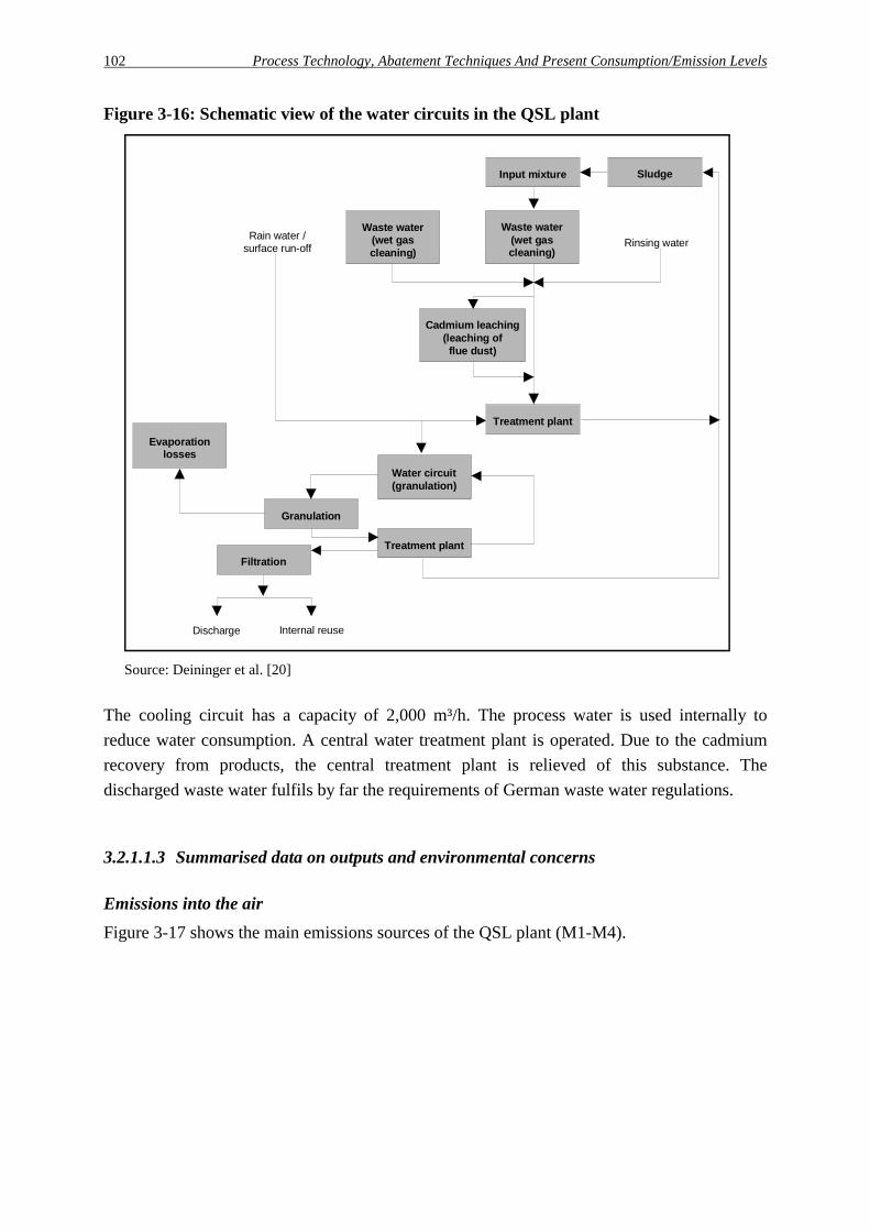
102 Process Technology, Abatement Techniques And Present Consumption/Emission Levels
Figure 3-16: Schematic view of the water circuits in the QSL plant
Input mixture Sludge
Waste water(wet gas cleaning)
Waste water(wet gas cleaning)
Rinsing water
Cadmium leaching(leaching of flue dust)
Treatment plant
Rain water /surface run-off
Water circuit(granulation)
Treatment plant
Granulation
Evaporationlosses
Filtration
Discharge Internal reuse
Source: Deininger et al. [20]
The cooling circuit has a capacity of 2,000 m³/h. The process water is used internally to reduce water consumption. A central water treatment plant is operated. Due to the cadmium recovery from products, the central treatment plant is relieved of this substance. The discharged waste water fulfils by far the requirements of German waste water regulations.
3.2.1.1.3 Summarised data on outputs and environmental concerns
Emissions into the air Figure 3-17 shows the main emissions sources of the QSL plant (M1-M4).

Process Technology, Abatement Techniques And Present Consumption/Emission Levels 103
Charge preparationand mixing
Inputs
Green pellets
Gas cleaninig
Slag
Lead bullion
Pre-decopperizing Refining
Pre-decopperizedlead bullion
Refinedlead
Sulphuric acid plant Off-gas
M 1
STACK
M 4Off-gas
QSL reactor
Bag filtersOff-gas M 2
Wet ESP
Slag granulation
Off-gas M 3
Off-gas Off-gas Various
by-products
Figure 3-17: Main sources of controlled emissions (QSL plant)
An overview of controlled emissions from the QSL plant is given in Table 3-44.
Table 3-44: Controlled emissions into the air from the QSL plant (annual average values)
Flow Main components (mg/Nm³) Process unit [Nm³/h] Dust Pb Cd SO2 NOx Raw material storage/ handling/refinery
220,000 1 - 2 0.2 - 1 0.005 - 0.05 20 - 200 10 - 20
Clean gas (sulphuric acid plant)
20,000 < 1 0.001 - 0.02 0.001 - 0.002 200 - 300 250 - 400
Slag granulation 190 1 - 5 0.5 - 2 < 0.001 < 20 < 10
Source: company information company L1, 1998
The content of PCDD/PCDF in the off-gases is less than 0.1 ng-TE/Nm³. Compared to the traditional lead production with the main emission sources sinter plant and blast furnace, the QSL plant is a low emission potential process as shown in Table 3-45. For example, the sulphur dioxide emissions into the air are considerably lower than from the conventional sinter plant - blast furnace route. In addition, a reduction of lead emissions to air has been achieved from 140 g/t lead for the conventional plant compared to 40 g/t lead for the QSL plant [7].

104 Process Technology, Abatement Techniques And Present Consumption/Emission Levels
Table 3-45: Comparison of controlled emissions from lead bullion production (QSL plant/conventional plant)
Components
QSL plant*) [t/a]
Conventional plant*) [t/a]
Reduction rate [%]
Dust 12.51) 20.2 38
Lead, total 5.21) 8.4 38
Process off-gas 0.1541) 2.12) 92.5
Cadmium, total 0.0251) 0.17 85
Process off-gas 0.01671) 0.252) 93
Zinc 0.651) 1.3 49
Arsenic 0.0721) 0.12 38
Sulphur dioxide, process off-gas
891) 2970 97
*) The calculations have been done for the same installed raw material capacity of 150,000 t/a
Source: 1) Deininger [19]; 2) Deininger et al. [20]
Waste water In Table 3-46 data on waste water from the QSL plant is summarised.
Table 3-46: Data on waste water from the QSL plant (annual average values)
Effluent Flow Main components [mg/l] Process unit [m³/a] [m³/h] Pb Cd As Zn Ni AOX CODWaste water treatment plant
90,000 10 0.1 < 0.05 < 0.05 0.3 < 0.05 < 0.1 20
Source: company information company L1, 1998
By-products and residues The granulated QSL furnace slag is of the iron silicate type with a slag basicity of 0.8 - 1.0. It has a zinc content of up to 15 % and can be used externally for different options e.g. in road construction [9]. The flue dust from the waste-heat boiler and the hot ESP is recirculated internally to charge preparation. To prevent cadmium enrichment in the process a certain amount (16 t dust per day) is continuously discharged and treated in a cadmium leaching plant. The recovered zinc-cadmium carbonate is dumped. Silver and other noble metals sre recovered from lead bullion during refining and then sold. An overview of the by-products and residues is given in Table 3-47.

Process Technology, Abatement Techniques And Present Consumption/Emission Levels 105
Table 3-47: By-products and residues from the QSL plant
Process unit
By-product/residue Amount [t/a]
Use/treatment option
Slag treatment Granulated slag 50,000 Used in certain road construction fields
Gas cleaning system Filter dust n. a. Recycling to smelting reactor Cadmium/chlorine removal
Calomel 2 - 5 Saleable by-product
Waste heat n. a. Power generation or turbines
Sulphuric acid plant Sulphuric acid 60,000 Saleable by-product
Refinery Doré metals (silver, ..) 250 Treated and/or sold
Cadmium leaching Zinc - cadmium carbonate 100 - 150 Dumping
Waste water treatment plant
Sludges n. a. Dumping
Source: company information company L1, 1998
Other environmental concerns The dust immisions in the vicinity of the plant L1 are shown in Table 3-48.19
Table 3-48: Dust immissions in the vicinity of the QSL plant (examples, 1991)
Element
Content in the suspended dust formation
[µg/Nm³]
Content in the dust sediment
[µg/m²d]
Source
Lead 0.1 - 0.51) 1202) [20]
Cadmium 0.002 - 0.0051) 52) [20] 1): The given range is valid for three different measurement stations in 1991. 2): These values are mean values of 24 measurement stations in 1991.
In the context of the plant modernisation, extensive investigations were performed to compare the former conventional lead production plant with the new QSL plant. Table 3-49 shows the energy-losses due to not-used heat streams in a QSL plant and in a conventional plant which shows a 50 % reduction in the QSL plant.
19 A detailed description of the determination of the emissions from the QSL plant and the immissions in the
vicinity of the plant is given in Deininger et al. [20].

106 Process Technology, Abatement Techniques And Present Consumption/Emission Levels
Table 3-49: Comparison of not-used energy streams (QSL plant/conventional plant)
Heat stream
QSL plant [GJ/h]
Conventional plant [GJ/h]
Cooling water and radiation (wall) 12.00 30.50
Off-gas 10.25 28.50
Sensible heat (lead) 1.45 1.45
Sensible heat (slag) 9.25 9.25
Sensible heat (sinter) - 8.70
Source: Deininger et al. [20]
Concerning energy consumption, the following comparisons can be made: Compared to conventional lead bullion production (sinter plant - blast furnace route) with a specific energy consumption of about 10,000 MJ/t Pb, a reduction of 30 % in the QSL plant can be achieved. As shown in Table 3-50, the specific energy input per ton of raw material input in a QSL plant is about 3,600 MJ including a credit for generated energy by the waste-heat boiler steam, whereas a conventional plant requires about 5,150 MJ.
Table 3-50: Consumption of primary energy (QSL plant/conventional plant)
Energy source
QSL plant*) [MJ/t raw material input]
Conventional plant [MJ/t raw material input]
Electricity - 938
Natural gas 741.5 348.5
Coal dust 2552 -
Coke - 3848
Oxygen**) 360 13
Sum 3653.5 5147.5 *): These values were determined at the plant site in 1992. **): This value gives the amount of electrical energy required for oxygen production.
Source: Deininger et al. [20]

Process Technology, Abatement Techniques And Present Consumption/Emission Levels 107
3.2.1.2 The Sirosmelt process (plant L2)
3.2.1.2.1 General information Company L2 operates a Sirosmelt process plant. This technology has replaced a conventional sinter plant - blast furnace route in the end of 1995. The Sirosmelt plant, shown schematically in Figure 3-18, consists of the following main process steps: the storage of raw materials and the charge preparation, the Sirosmelt reactor, the gas cleaning system, the sulphuric acid plant, the refining plant and the devices for slag processing.
Sirosmelt furnace
Mixing / pelletizing
Raw materials
Slag
Sulphuricacid plant
Sulphuric acid
Cadmium / chlorine leaching
Refining Refined lead
Gas cleaningsystem
Decopperising plant
Raw materials storage Gas cleaning
Off-gasDust
Exhaust air
Gas cleaning Exhaust air
Slag granulation
Lead bullion
Waste-heat boiler
Heat recoveryGas cleaning Off-gas
Granulated slag
Dust
Waste water treatment plant Off-gas
Mercury removal
Mercury sludge
Figure 3-18: Sirosmelt plant L2
In Table 3-51, input and output values of the Sirosmelt plant are given.
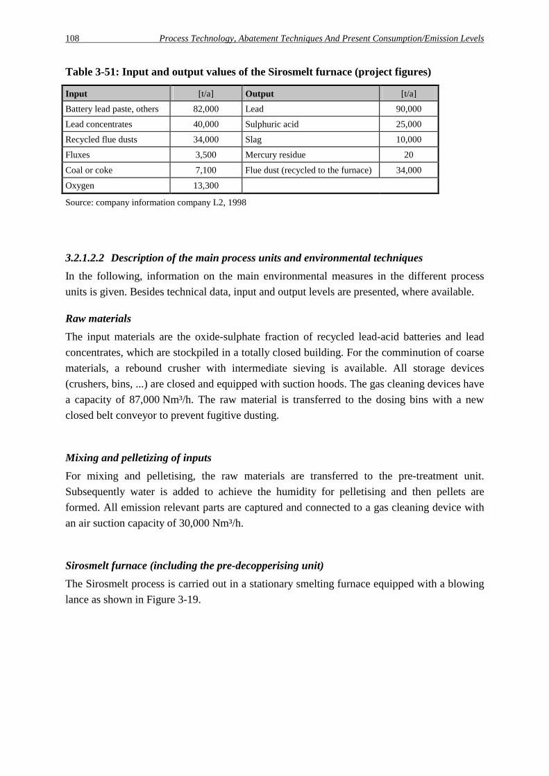
108 Process Technology, Abatement Techniques And Present Consumption/Emission Levels
Table 3-51: Input and output values of the Sirosmelt furnace (project figures)
Input [t/a] Output [t/a] Battery lead paste, others 82,000 Lead 90,000
Lead concentrates 40,000 Sulphuric acid 25,000
Recycled flue dusts 34,000 Slag 10,000
Fluxes 3,500 Mercury residue 20
Coal or coke 7,100 Flue dust (recycled to the furnace) 34,000
Oxygen 13,300
Source: company information company L2, 1998
3.2.1.2.2 Description of the main process units and environmental techniques In the following, information on the main environmental measures in the different process units is given. Besides technical data, input and output levels are presented, where available.
Raw materials The input materials are the oxide-sulphate fraction of recycled lead-acid batteries and lead concentrates, which are stockpiled in a totally closed building. For the comminution of coarse materials, a rebound crusher with intermediate sieving is available. All storage devices (crushers, bins, ...) are closed and equipped with suction hoods. The gas cleaning devices have a capacity of 87,000 Nm³/h. The raw material is transferred to the dosing bins with a new closed belt conveyor to prevent fugitive dusting.
Mixing and pelletizing of inputs For mixing and pelletising, the raw materials are transferred to the pre-treatment unit. Subsequently water is added to achieve the humidity for pelletising and then pellets are formed. All emission relevant parts are captured and connected to a gas cleaning device with an air suction capacity of 30,000 Nm³/h.
Sirosmelt furnace (including the pre-decopperising unit) The Sirosmelt process is carried out in a stationary smelting furnace equipped with a blowing lance as shown in Figure 3-19.

Process Technology, Abatement Techniques And Present Consumption/Emission Levels 109
Sirosmelt furnace
Slag Crude lead (todecopperisation)
Process gas (to gas cleaning system)
Lance lifting gear
Lance (in raised position)
Burner (natural gas)
Lance (in operation position)
Process air
Oxygen
Natural gas
Hood
Off-gas(to gas cleaning system)
Input charge(pelletized)
Off-gas(to gas cleaning)Off-gas
(to gas cleaning)
Hood
Figure 3-19: Schematic view of the Sirosmelt furnace
The height of the furnace is about 10 m with an inner diameter of 3.5 m. The furnace walls are cooled on the outer surface by water sprinkling, the inner side is refractory lined. The furnace is operated with two different campaigns: the smelting and the reduction campaign. For smelting, the raw material pellets are continuously charged into the furnace via a conveyor belt. A moveable lance is used to inject natural gas, oxygen and air into the bath. In the reducing atmosphere, the input charge is melted. In the roast reaction lead sulphides contained in the input charge react to liquid metallic lead and sulphur dioxide. A temperature of between 1,000°C and 1,100°C is obtained. A liquid lead phase and a liquid slag phase are achieved and continuously tapped. The process gases coming up from the bath are post combusted in the furnace gas atmosphere. At the resulting high temperatures, organic substances contained in the process gas like PCDD/PCDF are destroyed. The produced lead bullion is tapped continuously and led to the decopperising plant. The slag with a high lead content of up to 55 % is tapped, stored and further processed in the reduction campaign. This campaign is carried out discontinuously or continuously in the same furnace, if a certain amount of slag has been collected and the smelting campaign is finished. Within the reduction campaign, the slag from the smelting campaign and reducing agents like coal or coke are charged into the furnace. At temperatures of about 1,250°C additional lead bullion is produced and subsequently tapped. The lead content of the slag is reduced to 8 - 10 %. In the final fuming step, the lead but also the zinc content is lowered further by blowing

110 Process Technology, Abatement Techniques And Present Consumption/Emission Levels
of oxygen and coal into the furnace. Lead and zinc oxide containing flue dust is generated, collected in the process gas, precipitated in the gas cleaning system and intended for sale (e.g. zinc recovery). The decopperising of lead bullion is carried out in kettles. While the lead bullion cools, copper and other impurities separate as a lead-rich copper dross which is skimmed off. After Colcard decopperisation, the lead bullion is transferred to the refining plant. To prevent emissions into the air, the charging and the tapping area are equipped with hoods. The exhaust air is cleaned with bag filters.
Gas cleaning system (Sirosmelt furnace) The process gases are treated in a multistage gas cleaning system. First, the off-gases are cooled down in a waste-heat boiler following the circulating fluidised bed principle. The hot dust containing off-gas, which reaches the mixing chamber, is cooled down to 300 - 450°C immediately by recirculated flue dust. The recovered sensible off-gas heat is used for steam generation or water heating. In the next step, cyclones are used for coarse dust precipitation down to 30 - 45 g/Nm³. Precipitated dust which is not recirculated for cooling, is recycled to the charge preparation unit. Subsequently, the off-gas (200 - 350°C) is cleaned in two ESP and a Venturi scrubber for further dedusting. For final purification, another gas cooler and a two-stage wet ESP are used.
Sulphuric acid plant/mercury removal A double absorption contact plant is in operation to produce sulphuric acid by converting sulphur dioxide contained in the off-gas. Due to the fact, that several process steps are carried out in the reactor, the sulphur dioxide content varies considerably over time. For example, during smelting a high sulphur dioxide content is expected, but during reduction the content should be much lower. To permit efficient and stable contact plant operation, the off-gas is mixed with the off-gas from a neighbouring fluid bed zinc roaster. This ensures that the sulphur dioxide content is high enough for the double contact absorption plant. The acid from the drying steps collects the mercury of the process gases and is treated by using the Boliden Chemie process. Mercury is removed as a sludge by filtration of the acid. The sulphuric acid produced contains less than 0.5 g mercury/t.
Leaching of flue dust As most of the flue dust is recycled to the input mixing unit, cadmium and chlorine removal by leaching of flue dust may be necessary from time to time.

Process Technology, Abatement Techniques And Present Consumption/Emission Levels 111
Refining plant Lead bullion from the Sirosmelt furnace and purchased lead bullion from external smelters is refined in different steps, alloyed if necessary and cast into ingots of 50 kg weight. Therefore, the equipment of the refining plant consists of the following kettles and furnaces:
- 15 kettle furnaces with capacities between 100 t and 200 t, - three liquation furnaces - a Leferrer vacuum dezincing furnace, and - a cupellation furnace. The kettles and furnaces are covered with hoods which are ventilated via a central bag filter with an off-gas capacity of 80,000 Nm³/h.
Slag granulation After tapping, the slag is immediately granulated. The slag granulation is carried out with water and a redler equipped sedimentation basin is used for the separation of water and slag. During slag granulation, wet waste gases are emitted containing e.g. heavy metal dusts and vapours. These gases are captured with a volume of up to 13,000 Nm³/h and are cleaned in a wet ESP.
Water management/waste water treatment The waste water plant is used for the treatment of waste water not only from the lead plant but also from the neighbouring zinc electrolysis plant.
3.2.1.2.3 Summarised data on outputs and environmental concerns
Emissions into the air Table 3-52 shows the main controlled emissions into the air from the Sirosmelt plant. The main sources for emissions are the two or three tapholes, the exhaustion of machinery and the various slag and metal runners. Due to extensive capturing devices for storage and raw material transport, mixing and pelletising, total dust emissions are lowered e.g. for lead by 83 %.

112 Process Technology, Abatement Techniques And Present Consumption/Emission Levels
Table 3-52: Controlled emissions into the air from the Sirosmelt plant (1997)
Flow Main components (mg/Nm³) Process unit [Nm³/h] Dust Pb Cd SO2 NOx Raw material storage/handling 118,000 < 0.5 < 0.1 < 0.01 - -
Clean gas (sulphuric acid plant) 35,000 - - - 300 - 1,300 15 - 52
Slag granulation/furnace area 110,000 1 - 2 < 1 < 0.01 - -
Refinery 66,000 < 0.5 < 0.3 < 0.01 - -
Source: company information company L2, 1998
Compared to the conventional lead smelting route, a main feature of the Sirosmelt technology is the significantly lower sulphur dioxide emission (about 90 % lower). Table 3-53 shows the emission reduction achieved by plant modernisation at the plant site between 1990 and 1997.
Table 3-53: Emission reduction achieved by plant modernisation
Conventional plant (1990) [kg/a]
Sirosmelt plant (1997) [kg/a]
Reduction rate [%]
Emissions Controlled Fugitive Total Controlled Fugitive Total Controlled Fugitive Total
Lead 5,236 19,555 24,791 911 540 1,451 83 97 94.1
Cadmium 330 242 572 3.81 0.24 4.05 99 > 99 99.3
Antimony 151 309 460 25.8 1.77 27.52 83 > 99 94
Arsenic 77.6 141.5 219.1 4.03 1.55 5.58 95 99 97.5
Thallium 21.9 16.1 38 1.27 < 0.01 1.27 94 > 99 96.7
Mercury 16.7 0.4 17.1 0.87*) < 0.01 0.87 95 > 97 95
Sulphur dioxide [t/a]
7,085 - 7,085 140.4 - 140.4 98 - 98
*) The controlled mercury emissions from the Sirosmelt plant are given for 1996.
Source: Klotz [40], company information company L2, 1998
Waste water For the treatment of waste water, a central treatment plant is operated together with a neighboured zinc electrolysis plant. In Table 3-54 data on waste water discharged from this plant is summarised.
Table 3-54: Data on waste water from the Sirosmelt plant
Effluent Flow Main components [mg/l] Process unit [m³/a] [m³/h] Pb Cd As Zn AOX COD Waste water treatment plant
340,000 45 - 50 0.01 - 0.09 0.001 - 0.01 0.001 - 0.1 0.01 - 0.2 0.004 - 0.2 50 - 200
Source: company information company L2, 1998

Process Technology, Abatement Techniques And Present Consumption/Emission Levels 113
By-products and residues An overview of the by-products and residues is given in Table 3-55.
Table 3-55: By-products and residues from the Sirosmelt plant
Process unit
By-product/residue Amount [t/a]
Use/treatment option
Gas cleaning system Filter dust 34,000*) Internal recycling to reactor
Cadmium/chlorine leaching ESP dust n. a. Internal recycling
Sulphuric acid plant Sulphuric acid 25,000 Saleable by-product
Mercury residue 20 Internal recycling
Slag treatment Granulated slag 10,000 Road construction, concrete
Waste water treatment plant Sludges 200**) Dumping *) About 20% of the dust are leached; the arising filter cake is also recycled to the reactor. **) In this value, the zinc smelter waste water residue is contained.
Source: company information company L2, 1998

114 Process Technology, Abatement Techniques And Present Consumption/Emission Levels

Process Technology, Abatement Techniques And Present Consumption/Emission Levels 115
3.2.2 Lead recycling from secondary raw materials using a shaft furnace (plant L5)
3.2.2.1 General information
Company L5, a subsidiary of a battery producing company operates a recycling plant for used lead-acid batteries [91]. The process uses a shaft furnace to process whole batteries after the removal of acid. A schematic view of this process is given in Figure 3-20. As shown, the plant can be subdivided into the following production units:
- a shaft furnace with an annual production capacity of 35,000 tons crude lead, and - refining and alloying processes. This process is also operated in other European countries e.g. in Belgium, the Czech Republic, Russia and Sweden. The whole plant is already certified according to ISO 9002; while the certification according to the ISO 14001 and the EMAS will follow in 1998. In the following the shaft furnace process and the subsequent refining and alloying steps are discussed in detail.
Acid drainage
Crushing
Slag (return and excess)Matte
Post combustionTop gas
Bag filter Off-gas
Dust
Lead bullion
Refining
Used batteries
-Lead bearing wastes and residues- Lime stone- Ferrous scrap- Coke- Return slag- Dechlorinated dust
Injection oflimestone (optional)
Process air, oxygen enriched
Slag
Sulphuric acid
Battery scrap
Hygiene gas
Refined lead Dross
Fluxes
Shaft furnace
Tapping area
Slag treatment /Separation slag / matte
Figure 3-20: Shaft furnace plant L5 for recycling of lead-acid batteries
Table 3-56 gives an overview of the main input and output values in order to provide a first characterisation of this process.

116 Process Technology, Abatement Techniques And Present Consumption/Emission Levels
Table 3-56: Main input and output values from the shaft furnace recycling plant (1997)
Input [t/a] Output [t/a]
Old batteries, dry 33,000 Crude lead 30,000
Other lead scrap, waste 9,600 Flue dusts 950
Fluxes (limestone) 450 Excess slag 1,500
Coke (foundry coke) 3,600 Return slag 16,000 - 18,000
Other inputs (iron) 2,000 Iron/lead matte 4,200
Slag (return) n. a. Used sulphuric acid 3,350
Oxygen 1.3 Mio. Nm³
Lead carbonate (from flue dust treatment)
1,200
Natural gas 450,000 m³
Electrical energy 3.200 MWh
Source: company information company L5, 1998
3.2.2.2 Description of main process units and environmental techniques realised
In the following, detailed information on the main environmental measures in the different process units is given. Besides technical data, input and output levels are presented, where available.
Raw material handling First of all, the delivered batteries are crushed in order to remove the liquid acid, then they are stored in the storage yard. The battery scrap and other lead bearing wastes are mixed with additions as coke, limestone, iron scrap and return slag. To prevent fugitive non-captured dust emissions from storing, transport and handling, most input materials are moistened. As mentioned above, the waste battery acid is separated from the battery scrap. After a filtering step, it can be used for some applications replacing virgin sulphuric acid, e.g. for zinc leaching in zinc electrolysis or for waste water neutralisation in water treatment plants.
Shaft furnace The charge is fed directly into the shaft furnace using a shovel loader. The shaft furnace has a height of about 8 metres. It runs continuously in order to maintain stable conditions to produce a consistently high quality and a sound environmental performance. The furnace is relined less than once a year. To reduce and smelt the charge, oxygen enriched air is injected into the furnace. The produced lead bullion is tapped into a mould and cooled down for further treatment. The shaft furnace slag is tapped in special slag pots. In order to collect the emissions from tapping, secondary hoods are installed. After slow solidification, the iron, lead and sulphur containing matte can be separated from the Iron silicate slag. The matte is treated externally to recover sulphur, lead and copper. A typical composition of the shaft furnace slag is given in Table 3-57.
Table 3-57: Typical composition of shaft furnace slag

Process Technology, Abatement Techniques And Present Consumption/Emission Levels 117
Compound FeO SiO2 CaO Al2O3 Pb [wt.-%] 30 - 40 25 - 35 15 - 25 5 - 15 1 - 2
Source: company information company L5, 1998
The plastic materials contained in the inputs are volatilised in the upper zone of the furnace and leave the furnace with the off-gas. Other emissions from the process e.g. gaseous and particulate heavy metal emissions, are effectively collected together with the off-gas stream, and are then passed to the post combustion chamber of the gas cleaning system. Apart from the water for cooling purposes, no process water is used in the company L5 shaft furnace process itself. The specific input and output values of the shaft furnace process are given in Table 3-58.
Table 3-58: Specific input and output values of the shaft furnace plant L5 (1997)
Input [kg/t lead bullion] Output [kg/t lead bullion]
Used batteries, dry 1100 Lead bullion 1,000
Other lead scrap, waste 320 Flue dusts 32
Fluxes (limestone) 14 Excess slag 50
Coke (foundry coke) 109 Return slag n. a.
Other inputs (iron) 67 Off-gas 18,200 Nm³
Lead carbonate (from flue dust treatment)
40 Iron/lead matte 140
Slag (return) n. a.
Oxygen 43 Nm³
Natural gas 15 Nm³
Electrical energy 107 kWh
Source: company information company L5 (1998)
Gas cleaning system In order to prevent organic emissions, a post combustion chamber has been installed for burning combustible components. In this chamber, the gas is ignited by natural gas burners and burnt at temperatures of up to 1,100°C to remove any remaining hydrocarbons. The arising hot off-gases are cooled down rapidly (dry quenching) with the secondary off-gases and cleaned in a fabric filter. A dust content in the clean gas below 1 mg/Nm³ is achieved. A typical composition of cleaned off-gas is given in Table 3-59.

118 Process Technology, Abatement Techniques And Present Consumption/Emission Levels
Table 3-59: Typical data of the cleaned shaft furnace off-gas
Substance in the off-gas*) Content
Dust load [mg/Nm³] < 1.0
Lead [mg/Nm³] < 0.5
Cadmium [mg/Nm³] < 0.05
Carbontotal [mg/Nm³] < 10
Sulphur dioxide [mg/Nm³] < 500
Nitric oxide (NOx as NO2) [mg/Nm³] < 50
Carbon monoxide [mg/Nm³] < 50
Hydrochlorine (HCl) [mg/Nm³] < 5
Hydrofluorine (HF) [mg/Nm³] < 0.5
PCDD/PCDF (Σ TE, NATO) [ng-TE/Nm³] < 0.1
*) Off-gas stream: 65,000 Nm³/h
Source: company information company L5, 1998
The off-gas amounts to 65,000 Nm³/h. Emissions as dust, carbon monoxide and sulphur dioxide are monitored continuously. Calcium hydroxide additive can be injected into the off-gas channel, to prevent sulphur dioxide emissions peaks. The fabric filter dust has a lead content of up to 65 wt-% and can be recycled back to the smelting furnace as input material after chlorine removal. In order to achieve this, the filter dust is treated externally in a hydro-metallurgical process to produce lead carbonate. The lead carbonate is returned and fed as raw material to the shaft furnace.
Refining and alloying The refining and alloying of crude lead is carried out in refining kettles. To alloy the lead, it is remelted and alloying elements are added. Finally it is cast into ingots of approximately 40 kg each. During the refining and alloying of the crude lead, heavy metal emissions arise, for example, depending on the refining process operated. To collect these emissions, primary hoods for dedusting are arranged above the kettles. These are connected to the fabric filter.
Water management/waste water treatment A certain amount of water is used for regular wet cleaning of the plant site and vehicles. Wet cleaning of the site is done using a sweeping machine. Also all trucks are cleaned regularly. To close the water circuit, the used cleaning water as well as the rainwater is collected, and treated in an automatic water treatment plant in several chemical and physical cleaning steps. The quality of the cleaned water is monitored continuously. Part of the treated water from the water treatment plant is reused internally, and the remaining water is discharged. An analysis of discharged water is given in Table 3-61.

Process Technology, Abatement Techniques And Present Consumption/Emission Levels 119
3.2.2.3 Summarised data on outputs and environmental concerns
Emissions into the air Table 3-60 shows the main controlled emissions into the air from the shaft furnace plant L5.
Table 3-60: Typical controlled emissions into the air from the shaft furnace plant L5
Flow Main components [mg/Nm³] Process unit [Nm³/h] Dust Pb Cd SO2 NOx Gas cleaning system 65,000 < 1.0 < 0.5 < 0.05 < 500 < 50
Source: company information company L5, 1998
Waste water The only source of water discharges is the central water treatment plant, in which all water like cleaning water and rainwater is treated. Purified water not required internally is discharged. Data on waste water are given in Table 3-61.
Table 3-61: Typical data on waste water from the shaft furnace plant L5
Effluent Flow Main components [mg/l] Process unit [m³/a] [m³/h] Pb Cd Fe Zn Cu pH Waste water treatment plant 17,000 n. a. < 0.2 < 0.1 < 0.5 < 0.3 < 0.1 6.5 - 8.5
Source: company information company L5, 1998
By-products and residues About 95 % of the shaft furnace slag is fed back as return slag to the shaft furnace process, after the iron - lead matte has been separated after solidification [82]. Due to its physical and chemical properties, excess slag is used for road and pathway construction. The iron - lead matte consists primarily of iron, lead and sulphur and is sold to companies in the primary lead making industry for lead and sulphuric acid recovery. The lead dross arising from the refining processes is sold for metal recovery. An overview of the by-products and residues is given in Table 3-62.

120 Process Technology, Abatement Techniques And Present Consumption/Emission Levels
Table 3-62: By-products and residues from the shaft furnace plant L5 (1997)
Process unit
By-product/residue Amount [t/a]
Use/treatment option
Battery treatment Spent battery acid 3,350 External recycling
Shaft furnace Slag 1,500 Internal recycling Road construction
Flue dusts 950 External/internal recycling
Iron/lead matte 4,200 By-product for sale to primary lead production plants
Refining Lead dross 3,100 By-product for sale to metal recovery
Source: company information company L5, 1998
Other environmental concerns In the vicinity of the plant L5 the dust and lead immissions are monitored according to the German regulations TA Luft (c.f. Annex). Suspended dust collection gives immission values on a annual average basis for lead and inorganic lead compounds of less than 1 µg/Nm³. The dust sediment has a content of lead and inorganic lead compounds of less than 0.15 mg/m² per day.

Process Technology, Abatement Techniques And Present Consumption/Emission Levels 121
3.2.3 Lead production from secondary raw material using rotary furnaces
In Germany, several rotary furnaces are in operation for the processing of secondary raw materials. Among them, two types for the treatment of lead-acid batteries are in use:
- smelting after battery breaking, dismantling and separation into different materials fractions - smelting of entire batteries after acid drainage.
3.2.3.1 Rotary furnace plant L4
3.2.3.1.1 General information Since 1995, company L4 is operating a modern secondary lead production plant. At this location, lead production has a tradition over 600 years. About 40 Million DM have been invested for the modernisation of the old smelting plant. The new recycling process recovers lead from used lead-acid batteries. The process comprises the following main steps:
- treatment and separation of old batteries, - desulphurization of electrode paste using sodium hydroxide, - smelting in (two) short rotary furnaces, - refining and alloying of the lead bullion, and - incineration plant for hazardous waste. A schematic view of this process is given in Figure 3-21. A peculiarity of the site L4 is the integration of a modern waste incineration plant with a capacity of 33,000 t/a at the same location. Parts of the incineration plant capacity are used for thermal treatment of the company's own plastic wastes from battery recycling. Additionally special wastes from external sources are processed. The whole plant is certified according to ISO 9001, EMAS and ISO 14001 [6]. An overview of the specific input and output values of the lead recycling plant L4 as well as the waste incineration plant is given in Table 3-63 and Table 3-64.

122 Process Technology, Abatement Techniques And Present Consumption/Emission Levels
Crude lead
Lead-acid batteries
Lead scrap / lead residues
Combustiblewastes
Storage
Sulphuric acid
Polypropylene
Separators
Incineration plant
Paste
SteamFluedust
Slag
Grid metal
Surface and waste water
Heating /warm water
Sodium sulphate
Waste watertreatmentDesulphurized
paste
Discharged water
Sludge
Residues from smelting
Charge preparation
Short rotary furnace(s)
Pig lead
Refining andalloying
Flue dust
Casting machine
Refining dross
Lead and lead alloys
Treatment / separation
Desulphurization /crystallisation
Ebonite
Exhaust air(refinery)
Gas cleaning
Flue dust(internal recycling to charge preparation)
Figure 3-21: Lead recycling plant L4
Source: Behrendt et al. [6]

Process Technology, Abatement Techniques And Present Consumption/Emission Levels 123
Table 3-63: Specific annual input and output values of the lead recycling plant L4 (incl. refinery, 1997)
Input*) Output*)
Melting materials [t/t Pb] 1.41 Products
hereof: battery scrap [%] 79.0 Lead and lead alloys [t/t Pb] 1
Other melting materials [%] 3.8 Sodium sulphate [t/t Pb] 0.096
Bullion, scrap lead [%] 16.6 Polypropylene chips [t/t Pb] 0.051
Flue dust incinerator [%] 0.6 Wastes
Reagents [t/t Pb] 0.307 Residual plastics [t/t Pb] 0.108
hereof: NaOH [%] 49.8 Metallurgical slag [t/t Pb] 0.18
Steel borings [%] 9.4 Others: Exhaust gases [Nm³/t Pb] 37,000
Petrol coke [%] 17.6
Soda [%] 23.1
Others: Electric energy [MWh/t Pb] 0.20
Natural gas [MWh/t Pb] 0.73
Steam [MWh/t Pb] 0.84 *) As indicated, all figures are given per ton of lead and lead alloys produced.
Source: company information company L4, 1998
Table 3-64: Specific annual input and output values of the waste incineration plant (company L4, 1997)
Input*) Output*)
Residual plastics (own) [t/t Pb] 0.108 Steam [MWh/t Pb] 1.033
Other input [t/t Pb] 0.074 Incinerator slag [t/t Pb] 0.04
Water [m³/t Pb] 3.15 Flue dust (to lead smelter) [t/t Pb] 0.009
Electric energy [MWh/t Pb] 0.029 Waste water [m³/t Pb] 4.3
Natural gas [MWh/t Pb] 1.087 Exhaust gas [Nm³/t Pb] 2,000 *) As indicated, all figures are given per ton of lead and lead alloys produced.
Source: company information company L4, 1998
3.2.3.1.2 Description of the main process units and environmental techniques In the following, detailed information on the main environmental measures in the different process units is given. Besides technical data, input and output levels are presented, where available.
Raw material handling Lead-acid batteries are the main input material, other lead bearing wastes are only processed to a minor extent. First of all, the delivered batteries are stored in an acid-resistant, roofed storage yard. Most of the acid is drained and captured in a pump-sump, then filtered and

124 Process Technology, Abatement Techniques And Present Consumption/Emission Levels
collected for the neutralisation of surplus sodium hydroxide from the desulphurization plant. The old batteries are crushed and treated hydrodynamically by screening and separation in order to classify different fractions of polypropylene, ebonite, separators (PE, PVC, glass), metallic grid lead and electrode paste. The electrode paste, which contains sulphur as lead sulphate, is treated hydrometallurgically with sodium hydroxide. The lead sulphate reacts to sodium sulphate, water and lead oxide. The lead oxide is separated by filtering and then smelted.
Rotary furnaces For the smelting of raw materials, two short rotary furnaces are operated. Within these, different charges of lead containing substances, mainly metallic grid, returned filter dusts and desulphurised paste are smelted at 1,000°C in order to produce crude lead or partly a lead-antimony alloy for further processing in the refining plant. An automatic charging crane is used for charging the input materials. The furnaces, with a capacity of 5 m³ each, are totally encapsulated. The crude lead is tapped together with the slag into kettles by tilting the furnace. After a cooling down period, the lead bullion and slag are separated and transferred to the subsequent processing units. Emissions from smelting furnaces, like gaseous and particulate heavy metal emissions, are effectively collected from the waste process gas and passed to the gas cleaning system. The furnaces are totally encapsulated to prevent fugitive emissions from charging as well as from furnace operation.
Gas cleaning system (rotary furnaces) The furnace off-gas is cooled down for heat-recovery and steam is generated and used internally e.g. for dewatering or drying. A typical analysis of the clean gas from the smelting furnaces is given in Table 3-65.
Table 3-65: Typical average analysis of the clean gas from the short rotary furnaces
Main components [mg/Nm³] PCDD/PCDFProcess unit Dust Pb SO2 HCl NOx CO [ng-TE/Nm3]
Rotary furnaces A+B 0.15 - 0.52 0,04 - 0.1 86 < 5 15 - 20 94 - 108 0.08
Source: company information company L4 [62]
Refining plant The lead bullion is transferred to the refining plant. Up to 13 kettles are used for refining and alloying about 35 different qualities of lead and lead alloys. The resulting lead or lead alloys are cast in ingots (about 45 kg each) or blocks (about 1,000 kg each). Chemical reactions taking place during the refining and alloying of the lead give rise to various emissions in the refinery. The emissions depend on the type of refining process operated, whereby mainly heavy metal emissions arise. In order to collect these emissions, primary hoods for dedusting

Process Technology, Abatement Techniques And Present Consumption/Emission Levels 125
are arranged above the kettles and connected to a ventilation system. The off-gases are cleaned in fabric filters.
Waste incineration plant The waste incineration plant was technically revamped in 1996. The main feature of the new incineration plant is the modern gas cleaning system, which results in a high reduction of emissions. The off-gas from the waste incineration plant fulfils the requirements according to the German regulations 17. BImSchV. According to the operating permit, the maximum capacity for the rotary kiln operation is 33,000 t/a. The flue dust from the incineration plant gas cleaning devices shows a high lead content and is recycled to the rotary furnaces ([6],[7]). Altogether, about 99 % of the lead is recovered in solid products.
Waste water treatment plant All water used at the site is purified internally. The process water from battery treatment is recirculated. All the water used (e.g. process water, cleaning water) is collected and treated in the central water treatment plant.
Table 3-66: Annual average analysis of water discharges from the recycling plant L4
Element Pb Cd As Zn Ni COD AOX [mg/l] 0.15 0.007 0.07 0.42 0.11 43.0 0.23
Source: company information company L4 [62]
3.2.3.1.3 Summarised data on outputs and environmental concerns
Emissions into the air Table 3-67 shows the main controlled emissions into the air from the lead recycling plant L4.
Table 3-67: Controlled emissions into the air from the lead recycling plant L4
Flow Main components [g/t Pb] Process unit [Nm³/t Pb] Dust Pb SO2 NOx HCl Rotary furnaces (A + B), refinery 45,000 31 7 1,070 370 n. a.
Waste incineration plant 2,000 3 1.8 43 396 n. a.
Source: company information company L4, 1998
Waste water The water from the waste water treatment plant is discharged (c.f. Table 3-68). In 1996, 190,000 m³ water were discharged. Sludges from filtering are dewatered in a filter press and

126 Process Technology, Abatement Techniques And Present Consumption/Emission Levels
recycled to the smelting furnaces. In Table 3-68, data on the waste water which include surface waters is summarised.
Table 3-68: Data on waste water from the lead recycling plant L4
Effluent Flow Main components [g/t Pb] Process unit [m³/a] [m³/t Pb] Pb Cd As Zn Ni COD AOXWaste water treatment plant
190,000 4.3 1.4 0.09 0.5 1.6 0.7 225 0.4
Source: company L4 [62]
By-products and residues As mentioned above, the recovered sodium sulphate solution is crystallised, dried and sold as chemically pure sodium sulphate salt with less than 5 ppm lead. About 85 % of the sulphur is recovered this way. The polypropylene chips are recompounded in a recovering plant belonging to the subsidiary of the company L4. The produced high quality polypropylene granules are sold. A polypropylene recovery rate of more than 90 % is achieved. Plastic waste and other materials like ebonite that cannot be recycled are burnt in the incineration plant. Only process slag, that cannot be prevented or recycled has to be dumped. An overview of the by-products and residues is given in Table 3-69.
Table 3-69: By-products and residues from the lead recycling plant L4
Process unit
By-product/residue Amount [t/a]
Use/treatment option
Crystallisation plant Sodium sulphate 4,300 By-product for sale
Battery treatment PP granules 2,300 By-product for sale
Residual plastics 4,900 Waste incineration plant
Slag 8,100 Recycling, dumping
Short rotary furnaces Flue dusts n. a. Internal recycling
Source: company information company L4, 1998
Other environmental concerns Noise emissions have been reduced during recent years, e.g. by the encapsulation of main noise sources like ventilators.

Process Technology, Abatement Techniques And Present Consumption/Emission Levels 127
3.2.3.2 Rotary furnace plant L6
3.2.3.2.1 General information Since 1977, the company L6 has operated a secondary lead production plant. At this location, the lead production has a long tradition. A schematic view of the battery recycling process developed and operated by company L6 is given in Figure 3-22. The process plant L6 comprises the main steps [9]:
- treatment and separation of old batteries, - sale of sulphur-containing electrode paste or desulphurization with sodium hydroxide, - smelting in short rotary furnaces, and - refining and alloying of lead bullion. The process has several similarities with the lead recycling plant L4. A peculiarity of this site is the integration of the compoundation plant for polypropylene recovery since 1991. The whole plant is certified according to ISO 9001 and ISO 14001. An overview of input and output materials is given in Table 3-70.
Table 3-70: Specific annual input and output values of the recycling plant L6 (incl. refinery, 1997)
Input*) Output*)
Melting materials [t/t Pb] 2.12 Products
hereof: battery scrap [%] 63 Lead and lead alloys [t/t Pb] 1
Other melting materials [%] 21 Battery paste [t/t Pb] 0.5
Bullion, scrap lead [%] 16 Polypropylene compounds [t/t Pb] 0.14
Reagents [t/t Pb] 0.14 Wastes
hereof: Steel borings [%] 46 Residual plastics [t/t Pb] 0.035
Petrol coke [%] 32 Slag [t/t Pb] 0.23
Soda [%] 22 Others Exhaust gases [Nm³/t Pb] n. a.
Others: Electric energy [MWh/t Pb] 0.26
Natural gas [MWh/t Pb] 1.19
PP chips (external) [t/t Pb] 0.04 *) As indicated, all figures are given per ton of lead and lead alloys produced.
Source: company information company L6, 1998

128 Process Technology, Abatement Techniques And Present Consumption/Emission Levels
Storage
Crushing
Preparation
Neutralisation
Storage
Desulphurisation
Filtration
Paste
Filtration
Smelting
Refining
Lead bullion
Lead and lead alloys(soft lead, hard lead, PbCa lead)
BatteriesLead-containingmaterials (scrap, ashes, dross)
Grid metal
Acid (for external use)
PP chips
EbonitePVC, PE,....
Na2SO4
Crystallisationand
dryingSulphatic paste (for sale)
Furnace off-gas (to gas cleaning)
Flue dust
Slag
DrossLead bullionOther lead
Additions,reductants
Flue dust, dross
NaOH /Na2CO3-solutions
Ca(OH)2-solution
Exhaust air (to gas cleaning)
PP-crushing plant
Compoundation plant
"SECULENE"-PP
Acid
Figure 3-22: Process plant L6 for the recycling of used lead-acid batteries
Source: company information company L6, 1998
3.2.3.2.2 Description of the main process units and environmental techniques In the following, detailed information on the main environmental measures in the different process units is given. Besides technical data, input and output levels are presented, where available.
Raw material handling Lead-acid batteries are the main input materials. The delivered batteries are unloaded into an acid-resistant, roofed storage facility. Most of the acid with a sulphuric acid content of 8 - 15 % is drained and captured in a pump-sump for further use in the process. The batteries are crushed using a hammer crusher. By sieving the fine fraction, mainly lead paste, is separated for sale or for further internal processing. For desulphurization, the recovered lead paste is processed with caustic lye of soda or soda. The lead sulphate reacts to sodium sulphate, water and lead oxide or lead carbonate. The coarse fraction is treated hydrodynamically to classify polypropylene, a plastic fraction, and grid metal, which is used for the production of lead bullion alloyed with antimony.

Process Technology, Abatement Techniques And Present Consumption/Emission Levels 129
Waste acid is either sold as such as a neutralisation agent in the desulphurisation process or is neutralised with lime and processed with the sulphur containing paste.
Rotary furnaces For the production of crude lead, four short rotary furnaces with a capacity of 3.8 m³ each are operated. At temperatures of up to 1,200°C metallic grid, paste and other lead-bearing compounds are smelted. The heat is supplied by oxygen/natural gas burners. The off-gas produced in the rotary furnaces passes to the gas cleaning system. The molten lead bullion and the slag are separately tapped into moulds. The furnaces are encapsulated to prevent fugitive emissions. The desulphurized paste can also be processed in the rotary furnace. For this purpose, together with the paste, coke and fluxes are charged and lead bullion with a low antimony content is obtained. By processing of different mixtures of raw materials, the content of antimony in the lead bullion can be varied.
Gas cleaning system A fabric filter is used to reduce the dust emissions from the rotary furnaces, average emission values are indicated in Table 3-71. A specific off-gas amount of about 65,000 Nm³/h arise. After thermal granulation, the flue dust is precipitated and recycled to the smelting furnace.
Table 3-71: Typical average off-gas values (rotary furnaces)
Main components [mg/Nm³] PCDD/PCDFProcess unit Dust Pb Cd As SO2 HCl NOx [ng-TE/Nm3]
Rotary furnaces < 1 - 10 0.2 - 1 0.001 - 0.01 0.002 - 0.02 < 200 5 - 20 20 - 50 < 0.1 - 1
Source: company information company L6, 1998
Refining and alloying At plant L6 site, up to 10 kettles can be used for the refining and alloying of different lead and lead alloy qualities. The product is cast into ingots (about 50 kg each). Because of ongoing chemical reactions, various amounts of emissions arise in the refinery e.g. heavy metals depending on the refining process operated. For collecting these emissions, primary hoods connected to fabric filters are arranged above the kettles.
Compoundation plant The polypropylene fraction, recovered by the treatment of batteries in the separation plant, is processed in the compoundation plant. The ground polypropylene chips are compounded, and the manufactured product "Seculene�" can be used for different options, for example in the car manufacturing industry.

130 Process Technology, Abatement Techniques And Present Consumption/Emission Levels
Water management/waste water treatment The process water for the hydroseparation of battery scrap is used in cycles. All waters (e.g. process waters, cleaning water) are collected and treated in the central water treatment plant. The clean water from the water treatment plant is partly used internally. Sludges from filtering are dewatered in a filter press and recycled to the smelting furnaces.
3.2.3.2.3 Summarised data on outputs and environmental concerns
Emissions into the air Table 3-72 shows the main controlled emissions into the air from the lead recycling plant L6.
Table 3-72: Controlled emissions into the air from the lead recycling plant L6
Flow Main components [g/t Pb] Process unit [Nm³/t Pb] Dust Pb Cd SO2 NOx HCl Rotary furnaces (1 - 4) 9,600 < 10 - 100 2 - 10 0.001 - 0.01 < 2,000 200 - 500 50 - 200
Exhaust air (furnace area, refinery, ...)
21,000 2.1 - 69 0.2 - 2 0.4 - 8 < 440 n. a. 10 - 20
Source: company information company L6, 1998
Waste water All waters (e.g. process waters, cleaning water) are collected and treated in the central water treatment plant. The clean water from the water treatment plant is partly used internally. In Table 3-73, data on discharged waste water are summarised.
Table 3-73: Data on waste water from the lead recycling plant L6 (annual average values)
Effluent Flow Main components [mg/l] Process unit [m³/a] [m³/h] Pb Cd As Zn Ni COD AOXWaste water treatment plant1)
110,000 12.7 0.12 0.06 0.05 0.14 0.1 13 0.52
1): no production specific waste waters, only surface water
Source: company information company L6, 1998
By-products and residues The by-products and residues are shown in Table 3-74. The sodium sulphate solution is crystallised, dried and sold as chemically pure sodium sulphate salt to the glass or chemical industries. Process slag from the smelting furnaces, that can not be prevented or recycled is dumped.

Process Technology, Abatement Techniques And Present Consumption/Emission Levels 131
Table 3-74: By-products and residues from the lead recycling plant L6
Process unit
By-product/residue Amount [t/a]
Use/treatment option
Compoundation plant
PP compounds 4,800 By-product for sale
Battery treatment Sulphatic paste 17,000 Sale to primary lead production plants
Residual plastics 1,200 Dumping
Short rotary furnace Slag 7,800 Recycling, dumping
Flue dusts n. a. Internal recycling
Source: company information company L6, 1998
3.2.3.3 Rotary furnace plant L7
3.2.3.3.1 General information Facing a tradition of more than 450 years of lead processing, the company L7 operates a secondary lead smelting plant since 1971. The main source are spent lead-acid batteries ([56], [57]). The plant comprises the following main steps:
- battery treatment including waste water treatment and polypropylene upgrading, - smelting in a short rotary furnace, - refining plant (certified according to DIN ISO 9002). A schematic view of the lead recycling plant is given in Figure 3-23. The main capacity figures are given in Table 3-75.
Table 3-75: Main input and output capacity figures of plant L7
Input [t/a] Output [t/a]
Battery scrap 65,000 Refined lead and alloys 28,000
Battery plates 4,000 Battery paste 32,500
Scrap lead 6,000 PP fine grains 2,750
Ebonite and separators 3,500
Slag 3,300
Source: company information company L7, 1998

132 Process Technology, Abatement Techniques And Present Consumption/Emission Levels
Crusher Screener
Classifyer
Plastic fraction
Classifyer
Ebonite &separators
(for dumping)
Polypropylene(for sale)
Filter press
Oxide fraction(for sale)
Thickener
Waste watertreatment plant
Metal fraction
Short rotaryfurnace
Secondary materialsand additions
Slag (for dumping)
Intermediate products
Off-gas
Lead bullion
Refining
Alloying
Refined lead Metal scrap Alloying metals
Casting Lead and lead alloy (for sale)
Storage
Battery scrap
Gas cleaning
Filter dust
Acid
Figure 3-23: Lead recycling plant L7
3.2.3.3.2 Description of the main process units and environmental techniques In the following, detailed information on the main environmental measures in the different process units is given. Besides technical data, input and output levels are presented, where available.

Process Technology, Abatement Techniques And Present Consumption/Emission Levels 133
Raw materials The delivered batteries are stored in an acid resistant partly roofed storage area. The free acid is drained and directed to the waste water treatment installation. The batteries are crushed and separated in a battery treatment plant. Four different fractions are produced:
- the metal fraction consisting of poles, connectors and grids, - battery paste to be shipped to a primary lead production plant, - polypropylene chips for further treatment in the upgrading installation (washing and cutting
plus air-blowing), and - the separator and ebonite fraction for disposal.
Rotary furnace For the smelting of the lead containing materials, mainly the metal fraction from the battery treatment plant, but also drosses from the refinery and internal filter dusts, a short rotary furnace is used. The produced lead bullion is tapped into iron pots and transferred to the refinery. The slag produced in the rotary furnace is silica based and gives very low eluate values for lead. Therefore, the slag must not be dumped as hazardous waste.
Gas cleaning system By mixing with ventilation air, the furnace off-gas is cooled. For dedusting a bag filter (specific dust load: 0.7 m³/m²h) is used. The filter dust is wetted and returned back to the rotary furnace. A typical clean gas analysis is given in Table 3-76.
Table 3-76: Typical analysis of the clean gas from the rotary furnace (plant L7)
Main components [mg/Nm³] PCDD/PCDF Process unit Dust Pb SO2 HCl NOx [ng-TE/Nm3]
Rotary furnace gas cleaning 2 0.8 220 n. a. 20 < 0.1
Source: company information company L7, 1998
Refining plant The lead bullion is refined in up to 11 kettles with a capacity of 100 tons each. In order to meet customers’ specifications, about 40 different lead alloys are produced. Most of the lead produced is used by battery manufacturers. To collect the emissions from the kettles, a ventilation system with dedusting hoods is arranged above the kettles. The ventilation air is cleaned in a bag filter.

134 Process Technology, Abatement Techniques And Present Consumption/Emission Levels
3.2.3.3.3 Summarised data on outputs and environmental concerns
Emissions into the air Table 3-77 shows the main controlled emissions into the air from the lead recycling plant L7.
Table 3-77: Controlled emissions into the air from the lead smelting plant L7
Flow Main components [mg/Nm³] Process unit [Nm³/h] Dust Pb NOx SO2 Rotary furnace and refining plant 126,000 1.8 0.4 15 105
Source: company information company L7, 1998
Waste water The water from the waste water treatment plant is discharged, a typical analysis is given in Table 3-78.
Table 3-78: Data on waste water discharged from the lead smelting plant L7
Effluent Flow Main components [mg/l] Process unit [m³/a] [m³/h] Pb Cd As Zn Ni COD AOX Waste water treatment plant
124,000 n. a. 0.02 0.07 < 0.001 0.27 0.09 n. a. 0.2
Source: company information company L7, 1998
By-products and residues The fraction of separators and ebonite from the battery treatment plant and the slag from the short rotary furnace are dumped on an own dump at the plant site. Sludges from the water treatment plant contain the gypsum from the neutralisation of sulphuric acid and are sold as a part of the battery paste to a primary lead production plant.
3.2.3.4 Rotary furnace plant L8
3.2.3.4.1 General information Since 1960, the company L8 has operated a lead recycling plant.20 In 1992, several modernisation projects were realised to improve productivity and environmental performance. The plant comprises the following main steps:
- raw material handling, - smelting in short rotary furnaces, and - refining and alloying of lead bullion.
20 The information supplied in this chapter is mainly based on information given by the company L8 in 1998.

Process Technology, Abatement Techniques And Present Consumption/Emission Levels 135
An overview of input and output values is given in Table 3-79.
Table 3-79: Input and output values of the lead recycling plant L8
Input [t/a] Output [t/a]
Lead-containing materials 12,000 Lead bullion 10,000
Sodium carbonate 920 Dross 2,100
Coal 290 Lead-containing flue dust 240
Fuel oil 828 Slag 2,000
Oxygen 2 106 m3 Loaded adsorbent 87
Loaded adsorbent 87
Limestone additive 40
Lead containing flue dust 240
Antimony, antimony alloys 370
Pyrit 73
Source: company information company L8
3.2.3.4.2 Description of the main process units and environmental techniques
Raw materials For raw material, mainly used lead-acid batteries and residues from the lead-acid battery production are taken. In addition, several lead containing fractions are recycled internally, like filter dusts and sludges from the waste water treatment. The main other input materials are sodium carbonate, coal and to a smaller extent iron containing additives. After drainage, complete lead-acid batteries are charged without further preparation.
Rotary furnace A wheel loader is used for handling of raw materials. The furnace is charged via a charging wagon with a capacity of 4 - 5 tons of raw materials. Emissions from the charging area are captured by hoods. For each furnace charge, the charging wagon has to be loaded and unloaded into the furnace five to ten times. This frequency is determined by the composition of the input materials, e.g. the content of plastic material. The new wagon charge is not unloaded into the furnace until the plastic material from the last charge has burnt down. After the final wagon charge, the furnace is closed hydraulically. The tiltable furnace has a capacity of 25 tons, and a lead bullion production of about 18.6 tons per charge or 55 tons per day is achieved. For smelting the input charge, heat is supplied by an oil oxygen burner at the back of the furnace. Thus a considerable reduction of the energy consumption as well as the amount of the off-gas is realised. During the charging phase, the furnace off-gas amounts to about 5,000 Nm³/h. In the subsequent reduction phase, only 1,000 Nm³/h are exhausted. After the reduction is finished, the slag is tapped into the slag moulds. Afterwards the lead bullion is tapped into the lead moulds and transferred to the

136 Process Technology, Abatement Techniques And Present Consumption/Emission Levels
refining and alloying vessels. Due to its composition with a high content of water soluble sodium salts and heavy metal compounds, the slag has to be deposited.
Refining and alloying For refining and alloying, two oil and gas heated vessels with a capacity of 30 tons each are used. The emissions of the refining and alloying vessels are collected by hoods. The exhaust gas (up to 4,000 Nm³/h) is ventilated to the gas cleaning system, where a cyclone is used as the first cleaning device (c.f. Figure 3-24). Drosses are separated from the vessels with an automatic separation device.
Gas cleaning system A schematic view of the gas cleaning system is given in Figure 3-24. In the slag chamber, the hot off-gas with a temperature of about 1,200°C is cooled down to 250°C by mixing it with circulating air. After cooling down to a temperature of less than 120°C in a second cooler, the off-gases from the rotary furnace and the refining plant are cleaned in a two stage gas cleaning system. First a fabric filter with a filter area of about 160 m² is used. The precipitated dust from the two fabric filters is granulated by the addition of water and the dust pellets are re-processed into the furnace. For final purification, the pre-dusted off-gases are passed to an adsorption filter, where activated carbonised lignite is used as adsorbent. This filter consists of six parallel adsorbent boxes and permits the precipitation of vaporous and solid substances, like sulphur dioxide, heavy metal compounds and organic compounds. The loaded lignite is discharged from the boxes and used as a reduction agent in the rotary furnace. The clean gas composition given in Table 3-80 has been derived from sample measurements.
Table 3-80: Composition of the clean gas from the short rotary furnace (plant L8)
Main components [mg/Nm³] PCDD/PCDF Process unit Dust Pb SO2 HCl NOx [ng-TE/Nm3]
Rotary furnace gas cleaning 5 - 10 0.08 - 0.15 30 - 50 7 - 9 200 - 400 < 0.1
Source: company information company L8, 1998
If unusually high sulphur dioxide concentrations in the off-gas occur e.g. during the charging phase or the processing of loaded adsorbent, the injection of limestone additive and water after the cooling steps is foreseen.

Process Technology, Abatement Techniques And Present Consumption/Emission Levels 137
Short rotary furnace
Cyclone
1 2
Alloying vesselsDust filter 2
5,000 Nm3/h
Filter (with carbonized lignite injection)
Hall exhaustion
Charging unitmax. 37,000 Nm3/h
Dust filter 2
Stack
CoolerSlag cooling
Slag granulation unit
Figure 3-24: Modernised gas cleaning system of plant L8
3.2.3.4.3 Summarised data on outputs and environmental concerns
Emissions into the air Table 3-81 shows the main controlled emissions into the air from the lead recycling plant L8.
Table 3-81: Controlled emissions into the air from the lead recycling plant L8
Flow Main components [mg/Nm³] Process unit [Nm³/h] Dust Pb Cd SO2 Rotary furnace gas cleaning n. a. 5 - 10 0.08 - 0.15 n. a. 30 - 50
Source: company information company L8, 1998

138 Process Technology, Abatement Techniques And Present Consumption/Emission Levels
Waste water The waste water from the plant L8 is treated in the central waste water treatment plant of the neighboured lead batteries manufacturing plant. In Table 3-82, the permitted concentration limit values for clean water discharged from the waste water treatment plant are given. The regularly monitoring of the waste water treatment plant show, that the measured clean water concentrations are lower than the limit values.
Table 3-82: Data on waste water discharged from the company L8
Effluent Flow Main components [mg/l] Process unit [m³/a] [m³/h] Pb Cd As Zn Ni COD AOX Waste water treatment plant
150,000 40 0.4 0.01 < 0.001 0.01 < 0.05 96 0.25
Source: company information company L8, 1998
By-products and residues An annual quantity of 2,000 tons of furnace slag has to be deposited. The other solid outputs from the different processing units, mainly filter dusts, loaded adsorbent and lead dross, are recycled internally.
3.2.3.5 Rotary furnace plant L9
At the lead recycling plant L9 about 15,000 tons of lead bullion are produced per year from lead scrap and used lead-acid batteries. Lead scrap is processed together with drained batteries and fluxes in a short rotary furnace. The main products are lead-antimony alloy, used sulphuric acid, lead-iron matte, slag, and dust. - No further information available -
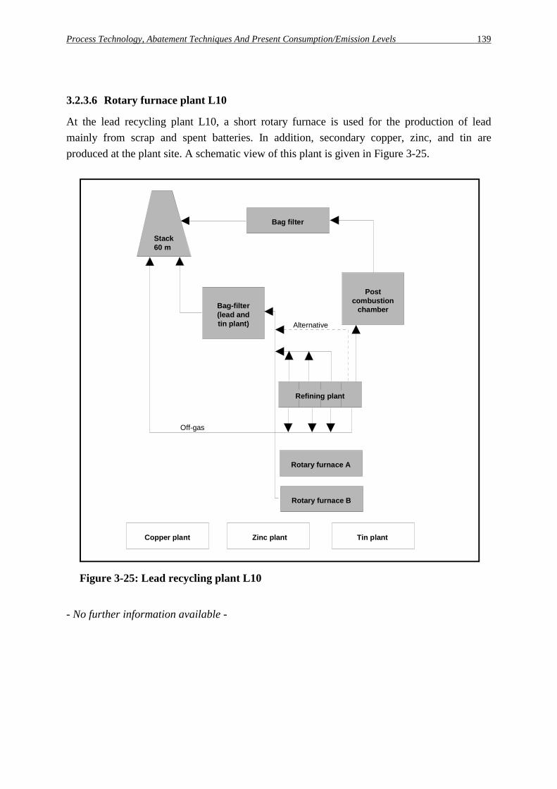
Process Technology, Abatement Techniques And Present Consumption/Emission Levels 139
3.2.3.6 Rotary furnace plant L10
At the lead recycling plant L10, a short rotary furnace is used for the production of lead mainly from scrap and spent batteries. In addition, secondary copper, zinc, and tin are produced at the plant site. A schematic view of this plant is given in Figure 3-25.
Stack60 m
Bag filter
Postcombustion
chamberBag-filter(lead andtin plant)
Refining plant
Off-gas
Rotary furnace A
Rotary furnace B
Alternative
Copper plant Zinc plant Tin plant
Figure 3-25: Lead recycling plant L10
- No further information available -

140 Process Technology, Abatement Techniques And Present Consumption/Emission Levels

German Candidate Best Available Techniques 141
4 German candidate best available techniques for integrated pollution prevention and control in the zinc and lead production
In this chapter, German candidates best available techniques (CBAT) will be described as a basis for the later determination of BAT on an EU level. For the identification of German CBAT, the IPPC-Directive, that is to say the definition of BAT in Art. 2.11 IPPC-D, serves as a basis: "Best available techniques shall mean the most effective and advanced stage in the development of activities and their methods of operation which indicate the practical suitability of particular techniques for providing in principle the basis for emission limit values designed to prevent and, where that is not practicable, generally to reduce emissions and the impact on the environment as a whole: Techniques shall include both the technology used and the way in which the installation is designed, built, maintained, operated and decommissioned, Available techniques shall mean those developed on a scale which allows implementation in the relevant industrial sector, under economically and technically viable conditions, taking into consideration the costs and advantages, whether or not the techniques are used or produced inside the Member State in question, as long as they are reasonably accessible to the operator. Best shall mean most-effective in achieving a high general level of protection of the environment as a whole." According to the IPPC-Directive, in the identification of BAT special consideration should be given to the following items listed in Annex IV:
- "the use of low-waste technology", - "the use of less hazardous substances", - "the furthering of recovery and recycling of substances generated and used in the process and
of waste, where appropriate", - "comparable processes, facilities or methods of operation which have been tried with success
on an industrial scale", - "the nature, effects and volume of the emissions concerned", - "the commissioning dates for new or existing installations", - "the consumption and nature of raw materials (including water) used in the process and their
energy efficiency", - "the need to prevent or reduce to a minimum the overall impact of the emissions on the
environment and the risk to it", and - "the need to prevent accidents and to minimise the consequences for the environment". First, general aspects and requirements valid for the production of zinc and lead in Germany are summarised (c.f. Chapter 4.1). Taken the information about the German plants and applied techniques (c.f. Chapter 2 and 3) into account, in the Sections 4.2 (zinc production) and 4.3

142 German Candidate Best Available Techniques
(lead production), individual techniques (which are considered to be "best available"-candidates) for each of the relevant production routes are presented. The achieved emission and emission load levels, given for each of the main production routes, have been reached with the processes in combination with the environmental measures. Since this report deals only with the processes and techniques operated in Germany, the derived German CBAT presents the situation in Germany. Other combinations of processes and environmental measures in operation within Europe have not been investigated.
4.1 General provisions and requirements for the prevention and control of environmental pollution In the following sections general measures are presented, which can be applied to prevent and control emissions into the atmosphere as well as discharges of waste water and to prevent the formation of solid wastes. In addition measures and general rules for other areas of environmental concerns as noise, plant safety and energy use are described. Only a short overview will be given, detailed technical information can be found elsewhere e.g. in Oslo and Paris Commission [65] and Zierock [114].
4.1.1 Techniques to prevent and control emissions into the atmosphere
Emissions into the atmosphere can be subdivided into fugitive and controlled (or stack) emissions. Controlled emissions are all captured emissions, which can usually be treated with appropriate gas cleaning devices. Sources for fugitive emissions are roofs and openings of production buildings as well as inadequate enclosed transport system and leakages. They also can arise during open handling and storing of materials. An overview on the relevant emissions and emissions sources in zinc and lead production plants has already been given in Chapter 2. In order to prevent and control emissions into the atmosphere, different so-called primary and secondary measures can be applied. Since most of the primary measures that prevent the formation of contaminants during the production process, are mainly process specific, they are discussed in the later Chapters 4.2 or 4.3.
4.1.1.1 Measures for the prevention of fugitive emissions
The contribution of fugitive emissions to the total emissions from a plant site can be very significant and, if appropriate cleaning of the captured gases is applied, exceed in most cases the controlled (stack) emissions. In the following, general measures to prevent and to capture fugitive emissions from storage, handling and transfer operations of dusty materials and from the operation of production and recycling units are summarised. It should be mentioned, that, as a rule, these measures are wide-spread although their realisation strongly depends on the site-specific constraints.

German Candidate Best Available Techniques 143
Storage, handling and transfer operations of dusty materials During storing, handling and transfer of materials consisting of fine particles such as concentrates, drosses and filter dusts, emissions of particulate matter can occur. When these dusty materials are stored, the following measures can help to reduce fugitive emissions:
- roofing and complete side coverage for bulk good storage including secondary facilities, - capturing of exhaust air and adequate cleaning (c.f. Section 4.1.1.2), - storage in closed container (protection against wind-blown emissions), - coverage of the surface, e.g. with mats, - planting of green belt to protect against wind erosion, - establishing overgrown earth embankment, windbreak plantings or windbreak hedges, - achieve and maintain a sufficient surface moisture level, i.e. with sprinkler. In order to prevent fugitive emissions from the handling of dusty materials, the following measures can be applied:
- delivery of raw materials in non-dusting form (wetted, pelletized, briquetted) or in packed form (drums, bins, Big-bags, containers, etc.) Raw materials can be received wetted as far as the process technology is suited for the processing of an additional water input,
- complete enclosure of the machinery, equipment and other facilities used for the treatment or production of dusty goods, and
- installation of exhausters and dedusting devices at main emission relevant parts, i.e. stationary reception, transfer and discharge points of concentrates, shovel loaders and transport units, downspout of loading facilities.
When dusty materials are transported, the following measures can prevent fugitive emissions:
- careful on-site traffic management is required (e.g. minimisation of transport events, restriction for vehicles to designated ways, functions and areas),
- reduced speed for vehicles at the plant site, - roads should be well defined, well maintained, kerbed, cambered and gullyed to obtain a
maximum run-off and collection of water, - roads should be kept wet after cleaning when appropriate, - regular cleaning of access roads with cleaning machines, - reduction of vehicle contact with the stockpile, - usage of adequate in-plant transport facilities, like pneumatic transport systems or special
equipped conveyor systems with ventilation to a filter system, and - careful cleaning of vehicles, especially their wheels, before leaving plant site.
Operation of production and recycling units In order to prevent fugitive emissions during the operation of production and recycling units, devices for the extraction of process gases should be applied at emissions sources such as furnaces, launders, melting pots, crushers for recycling material, etc. The extraction volumes

144 German Candidate Best Available Techniques
of these devices should be sufficient to cope also with abnormal operation conditions and overloads. The captured off-gases should be adequately cleaned (c.f. Section 4.1.1.2). Encap-sulating measures can include:
- enhousing of furnaces, - lock chambers on charging systems, - close hooding at tapping points, - dog-house for ladles during tapping, - enclosure of hot drossing areas, and - arrestment devices for crushers. To prevent emissions of particulate matter in the working area, high capacity vacuum cleaning systems should be used for cleaning and maintenance works. For storing, handling and transport of materials containing higher concentrations of lead, cadmium, or other harmful substances, the most efficient measures should be taken.
4.1.1.2 Techniques for the treatment of controlled emissions
Depending on their physical state, contaminants contained in the gas streams can be classified into gases, vapours and particulate matter. For removal of these contaminants from the gas streams (process gas, exhaust air), different gas cleaning devices are available as shown in the examples in Table 4-1. Normally dry off-gas cleaning is applied. But for certain cases, for example if gaseous compounds or vapours such as mercury vapour have to be precipitated, may additional wet gas cleaning be necessary. Wet gas cleaning is also applied for the cleaning of off-gases with a very high humidity. When choosing a gas cleaning device, in each specific case the following criteria have to be considered:
- process and operation characteristics, - raw gas characteristic: temperature, humidity, composition, flow, etc., - dust characteristic: mass flow, grain size distribution, etc., - space requirements, - separation efficiency, clean dust content, and - operation safety, capital expenditure and operation costs As an example, different gas cleaning techniques to remove certain gaseous contaminants and vapours are shown in Table 4-2. The double function of sulphuric acid plants used in the zinc and lead production plants is the removal of sulphur dioxide from the off-gas and the recovery of sulphuric acid as an by-product (c.f. Table 4-2).

German Candidate Best Available Techniques 145
Table 4-1: Different gas cleaning devices (examples)
Removal of ... Gas cleaning device Remark/example Reference Particulate matter Settling chambers - -
Cyclones Used as pre-precipitator device VDI 3676 [104]
Electrostatic precipitators - Dry - Wet
- Dedusting of SO2-containing off-gases (dry/wet ESP) - off-gas from slag granulation (wet ESP)
VDI 3678 [106]
Scrubber (wet separators for particle collection)
Removal of SO2, acid mists, ... Use of water requires water treatment and corrosion control in most cases
VDI 3679 [107]
Fabric filter (filtering separators)
Fabric filters are the most used filtering system. Adequate filter materials have to be selected (elevated temperatures)
VDI 3677 [105]
Gaseous contami-nants and vapours
Absorption into a liquid using packed, plate or spray towers
Boliden/Norzink process for the removal of mercury
VDI 3679 [108]
Adsorption on a solid in a fixed bed
Lead sulphide process for the removal of mercury
VDI 3674 [103]
Chemical conversion using a catalytic reactor
- VDI 3476 [101]
Table 4-2: Techniques to remove gaseous contaminants (examples)
Substance to remove Process Remarks Sulphur dioxide Recovery of sulphuric acid in
- Single contact plant - Double contact plant1) - Wet catalysis - Processes based on NOx
- minimum SO2 concentration necessary - steady off-gas conditions necessary
Recovery as liquid sulphur dioxides by - Condensation processes - Absorption processes
-
Recovery as elemental sulphur -
Dry sorption of SO2 by calcium oxide SO2 concentration too low for contact acid plant, unsteady conditions
Mercury vapour Wet absorption processes: - Selenium filter - Boliden/Norzink process1) - Sodium sulphate process1)
- subsequent sulphuric acid recovery
Dry adsorption processes: - Activated carbon filter - Lead sulphide process
-
Carbon monoxide and volatile organic compounds
Post-combustion (afterburning) chamber1)
-
1): Among others, these techniques are applied in the German zinc and lead production plants. Source: according to Osparcom [65]

146 German Candidate Best Available Techniques
4.1.2 Techniques for the reduction of water consumption and the control and treatment of waste water (water management)
The sources and the composition of waste water discharged from zinc and lead production plants have been summarised in Chapter 2 and 3. As shown, the main liquid effluent arising in zinc and lead production are from cooling, slag granulation, surface run off and wet gas cleaning operations. In the following, general techniques for the prevention of uncontrolled discharges, the reduction of water consumption and the volume of waste water, and the end of pipe treatment of waste water are summarised. It has to be mentioned, that the waste water situation in non-ferrous metal production plants is strongly determined by site specific conditions [94]. Main location dependent factors are the availability of water, especially for cooling purposes and the existence of a communal waste water system and the possibility to use a public sewage water system after pre-treatment of the effluents. In general, measures in order to prevent uncontrolled discharges due to leakages or accidents are necessary. These measures should include facilities to contain process waters, site drainage waters, emergency fire water and chemically contaminated waters. Bunding of storage tanks or double walls for tanks are essential in many cases, where there is a risk to controlled waters, sewers and drains, and on-site effluent treatment plants. Shared bunds are possible in cases where the materials stored are not incompatible. Depending on the specific potential for water pollution of the substances, different retention capacities have to be foreseen. High level alarms and trips on storage tanks should be designed according to the requirements. These devices as well as bunds should be inspected on a regular basis, especially where corrosive substances are involved. To reduce the water consumption and the volume of waste water process integrated measures, such as recycling and reuse are applied. End of pipe treatment is necessary in order to control the pollutant load of the effluents. In order to prevent uncontrolled discharges that may arise due to leakages or accidents safety of devices such as collecting basins are used. For the prevention of accidents and the minimisation of their consequences, several safety measures have to be applied (c.f. Section 4.1.6). Waste water systems have to be monitored and maintained on a regularly basis, especially systems which are installed underground.
Process integrated measures The most important process integrated measures in order to limit the volume of liquid effluents are based upon recycling and/or reuse techniques. Recycling involves the recirculation of process water to the process it was generated by. This usually requires the application of a basic treatment technique or the removal of a blowdown, to prevent the build up of suspended solids and metals in the recycling system. Where not practicable, water should be reused. This involves the recirculation of water for use in a process other than it was generated by. In practice several liquid effluent streams are usually fed into the same

German Candidate Best Available Techniques 147
system, pre-treated to prevent the build-up of suspended solids and metals, and then used in a variety of process applications. Process integrated measures to limit the volume of effluent also include the use of dry gas cleaning devices instead of wet gas cleaning wherever possible and the reuse of surface run-off as process water. Good management practices during operation or maintenance should be applied to minimise the pollutant load of oils and greases. The effectiveness of the end of pipe treatment may be improved by separating cooling water from e.g. process water with a higher pollutant load. Effluents containing cadmium, mercury, or other harmful substances at higher concentration levels should be pretreated before they are discharged to the final treatment plant.
End of pipe treatment Contaminated water generated by the non-ferrous metal industry is usually characterised by the presence of elevated metal concentrations (for example lead, copper, tin, zinc, cadmium, mercury, and chromium) as well as suspended solids. So the end of pipe treatment techniques used in the plants have been selected in order to minimise the concentration of these pollutants in final effluent discharges to the aquatic environment. The treatment of the waste water of the whole facility is usually done in a central waste water treatment plant but depending on the site specific conditions plants can be connected to an urban waste water system where the end of pipe treatment is applied. Because of different pollutant loads, the effectiveness of the end of pipe treatment may be improved by separating cooling water, surface runoff water from roofs and roadways and stockyard as well as process water or by use and reuse of water in decades depending from the demands for the water to be used. If the treatment is carried out at the plant site, the waste water from the different production plants is usually brought together in a collecting tank. If necessary, surface water is collected in a separate tank and is then usually supplied to the collecting tank to guarantee a more constant flow. Only a few companies treat their surface water in an extra facility. The tank for the surface water has to be dimensioned to handle also storm water rainfalls. In the collecting tank, oil, grease and plastics are removed mechanically. The subsequent treatment is based on chemical precipitation and neutralisation, sedimentation and filtration or centrifugation. Devices for waste water treatment are described in Table 4-3.

148 German Candidate Best Available Techniques
Table 4-3: Main devices for waste water treatment
Process step Principle Device Remark Precipitation and neutralisation
Chemical precipitation: forming of insoluble complexes by addition of precipitants, adjustment of pH
Precipitation reactor, tanks
To remove heavy metals, hydroxides and sulphides are used as precipitants; ferric sulphate may be used to eliminate the surplus sulphide
Solids separation
Sedimentation: Settling due to gravity, often use of additional flocculants
Clarifier, two compartment tank, cyclators
Flocculants: polymers
Polishing step Filtration Gravity filter
Precipitate dewatering
Filtration, centrifugation
Belt filter, vacuum filter (rotary drum filter), filter press, cyclone
Dewatered sludge is recycled to the metal production process or dumped
Especially where large discharges of effluent with high or low pH are possible, consideration should be given to a two or three stage pH control system. Dosing systems are unable to cope with effluent with extreme pH; therefore, an intermediate facility capable of storing acidic or alkaline effluent should be installed with an automatic control, if such effluents are likely. For highest demands, self-redundant systems should be used. Final discharges should be monitored at a minimum flow-rate, pH-value as well as temperature, and, if necessary, for other components of interest. In selecting an appropriate separation technique, consideration should be given to such factors as:
- current industry practice for the same or similar waste waters; - ability to produce an effluent with the desired characteristics; - characteristics of the concentrated solids that are produced; - mechanical simplicity; - reliability of equipment operation; - controllability of the process; - space requirements, and - investments and operating costs.
4.1.3 Management of by-products and waste
As shown in Chapter 2 and 3, solid materials arise during the production of non-ferrous metals in the different process units, mainly:
- slags, mattes and drosses removed during pyrometallurgical processes, - dust recovered from dry gas cleaning, - solids from leaching processes, - solids generated by the preparation of secondary feedstock and - sludge from liquid effluent treatment.

German Candidate Best Available Techniques 149
In the following it is mainly dealt with measures and techniques for the recycling/reuse of solid materials generated and for the minimisation and handling of waste. In lead and zinc production, only small amounts of waste material arise compared to the throughput of raw materials, because it has traditionally been the objective of the processing technology to produce as many constituents as possible in a marketable form and thereby to close the material cycle. This may be done within one company or in co-operation with other companies. The various chemical and physical properties of the substances are used to extract the individual constituents. These are, for example:
- distribution of substances between the molten and gas phase: components as tin, cadmium, arsenic, zinc, lead and their compounds, in particular, are volatilised, discharged from the production process with the off-gas and collected in gas cleaning plants in the form of flue dusts and extracted from the latter,
- different distribution coefficients of molten materials in non-miscible molten phases (for example, matte and slag),
- non-miscibility and insolubility of solid phases in liquid phases: separation of solid substances from melts (for example liquations, dross, skimmings) or from aqueous solutions (sludges, precipitates).
In this way, even traces of substances in the raw materials can be obtained in a marketable form, as shown in the following for the lead production industry: In primary lead production the concentrates contain mainly lead, iron, zinc and sulphur and in minor concentrations precious metals. Silica or lime are added as a flux. Consequently, besides lead, iron silicate slag, sulphuric acid, and Doré silver are produced. Sulphuric acid is widely used e.g. in the chemical industry. The iron silicate slag is normally granulated and can be used as a construction material (as a substitute for special sand qualities). In any case, the slag pro-duction is carried out with regard to common product standards, such as DIN EN ISO 11 126 Part 3 and VBG 48 for blasting materials as well as [109] and different technical guidelines for construction materials. The same passes for iron silica-slag from secondary production, which has a similar chemical and mineral composition and which can be used in the same fields of application. Other by-products from primary and secondary lead production are mattes, drosses, spent battery acid, flues dusts, Calomel. Metal wastes arise only if the demand is not sufficient, which is the case for e.g. cadmium or arsenic. In this case the surplus tonnage is safely disposed in special dumps. Other wastes which cannot be avoided are sludges from the waste water treatment plants or from the cooling water treatment, sweepings from paved areas and plants, used operation materials such as filter materials, conveyor belts, pallet wood, paper, oils, emulsions, ion exchangers from the boiler feed-water treatment, packaging materials, insulating materials,

150 German Candidate Best Available Techniques
furnace linings etc. If possible, those wastes should be used in recovery operations. Typically sludges from the waste water treatment plant, sweepings from paved areas and plants, filter materials and insulating materials are recirculated to the smelter. According to the European guideline 75/442/EEC, recovery operations are
- R 1: Use as a fuel (other than in direct incineration) or other means to generate energy - R 2: Solvent reclamation / regeneration - R 3: Recycling / reclamation of organic substances which are not used as solvents - R 4: Recycling / reclamation of metals and metal compounds, etc. This means wastes can be utilised in a material manner or can be used for the generation of energy. Priority should be given to this kind of utilisation with less environmental impact. Only if recovery is not possible according to the rules and without causing damage, should wastes be disposed of. This should be done in an approved manner in adequate facilities at the production site or at the nearest available site and it should be specified how the accumulation and storage of waste has to be controlled.
4.1.4 Energy aspects
In general, the optimal solution in terms of energy technology depends on the specific conditions existing at the site. According to the German Umweltbundesamt [87], an appropriate way of finding this solution is to draw up an energy utilisation concept which combines technical and economic objectives and eliminates information deficits. This general concept specifies economically feasible measures to be taken to optimise energy use and is structured as follows [87]:
1. An overview of the plants operated at the site and of their energy demand in terms of fuel and power demand.
2. Information on energy use inside the plants prior to site-specific optimisation, particularly - types and amounts of energy supplied to and removed from the plant, the most important
reactions and their enthalpies including main parameters, - description of the plant; energy balance, flow charts. 3. Description of energy use inside the plant after its energetic optimisation (as under 2.
above), including description of envisaged measures. Certain measures are applied in the zinc and lead production industry in order to minimise energy consumption or to recover waste heat that is produced. In the processes, the fuel value of the feed material is used to decrease the amount of energy supply needed. Hot charging of intermediate products where possible or continuously working plants minimise the additional energy supply, since the material has not to be remelted in every process step. The surplus reaction heat can be used as substitute for fossil fuel or to melt additional scrap or internal reverts.
German Candidate Best Available Techniques 151
The utilisation of waste heat has a long tradition for some types of furnaces, but in some cases it is difficult, with the result that no effective solutions exist today for various sub-regions. In general the devices for using waste heat are designed in order to maintain plant availability, so they are not optimised with regard to maximising energy efficiency.
4.1.5 Noise aspects/abatement techniques
In the planning and operation of installations, all technical, structural, organisational and planning-related measures must already be taken into account during the planning phase, in a manner appropriate to the respective local operating situation and in consultation with acoustic experts. Acoustic experts should be consulted throughout construction and their advice should be taken into particular account. Use should primarily be made of technical and planning-related noise prevention measures. In general, the following have to be considered:
Technical measures - Obtaining information at an early stage about noise emissions of machinery, installations and
parts thereof, and of work and production processes, - use of low-noise machines and processes, - reduction of noise generation and transmission, - reduction of sound emission of, e.g. by the use of sound absorbers, and - maintenance of machinery and soundproofing equipment.
Structural measures By means of secondary soundproofing measures such as encapsulation, absorbing walls and buildings, further noise reduction can be achieved. The absorption of air-borne sound by space-enclosing structural components primarily depends on their surface area and good sealing. Structural measures to reduce the transmission of structure-borne sound (e.g. partition joints, appropriate foundations) are necessary if a high level of structure-borne sound is expected to emanate from the building as a result of e.g. noise emission from machinery, rolling operations or vibration.
Organisational and planning-related measures Additional reductions in noise emissions as a function of local conditions can be achieved by organisational and planning related measures, such as accumulating high-noise sources and increasing the distance between noise sources and affected areas. In addition, operation restrictions may have to be imposed in special cases to reduce noise emissions. The exploration of suitable sites under consideration of the existing noise sources is of particular importance. Noise emissions from traffic to and from installations, which arise in connection with their operation must likewise be taken into account.

152 German Candidate Best Available Techniques
4.1.6 Plant safety aspects
According to the German Umweltbundesamt [87], the general policy for the prevention of, preparedness for and response to industrial accidents is based on the following principles:
Prevention principle - The plant should be constructed and operated in such a way as to prevent the uncontrolled
development of normal operation, - the plant should be constructed and operated in such a way that consequences of accidents
are reduced, - the plant should be constructed and operated according to the best available safety
techniques (state of the art safety technology).
Consideration of complex systems in process industries Complex systems can only be sufficiently examined by means of systematic, logical methods.
This is taken into account by applying system-analytical investigation methods and detailed safety analysis considering the conditions of the individual case.
Appropriateness of means Safety requirements are graded according to "type and scope of hazards to be expected". To
this end, rules are set up for substances relevant to accidents (substance criteria, list of substances) and industrial activities relevant to accidents (list of plants). The objective dependence of the disaster potential upon the quantity of hazardous substances is considered by a quantity threshold concept that defines staged safety requirements as a function of quantity [87].
4.1.7 Plant operation and decommissioning
Operational control plays an important role in the reduction of emissions. Special attention should be paid to the maintenance of equipment, malfunctions and breakdowns as well as supervision and training [114]. With regard to the cessation of activities, and in order to avoid any pollution risk and to return the site of operation to a satisfactory state, soil protection is of major importance. According to German Umweltbundesamt [87], an integrated approach requires that at least the following precautions have to be taken:

German Candidate Best Available Techniques 153
1) to minimise the amount of soil that needs to be excavated or replaced due to construction measures and to make sure that excavated soil material is treated carefully (in order to avoid harmful changes of soil properties),
2) to minimise the additional input of substances into the soil during the operation phase of a facility (e.g. additional input due to deposition of airborne substances should not lead to precautionary soil levels being exceeded and spillages should be avoided),
3) to ensure a clean closure when a facility is shut down, e.g. cleaning up and rehabilitation of contaminated soil, cleanup or securing of environmental hazards of hazardous landfills, with regard to the future use of the area. Natural soil functions should be safeguarded, if feasible.
4.1.8 Measurement of emission values
The following section is intended to ensure that the emissions specified in the whole report and in Chapters 4.2 and 4.3, in particular, are measured in such a way that the results are representative, mutually comparable and clearly describe the relevant operating state of the plant.
Measurement Planning The objective and scope of measurements are governed by the requirements in the approval decision or by particular events. In principle, the measurements serve to determine substances in the clean gas. Measurement planning should take account of the mode of operation and the operating state of off-gas purification plants, operating conditions in the plant (continuous, discontinuous, start-up and shut-down operations, load change) and the effect of thermodynamic interference factors. These data form the basis for determining the selection of operating conditions at which the highest emissions will presumably be recorded, the number and duration of the measurements, the method of measurement to be chosen, and the position of the measurement locations and points. In the case of continuous and batch-wise operation, a sample collection time or measurement time of half an hour (half-hour mean value) is, as a rule, necessary. If dust contents are low or if PCDD/PCDF are to be determined, other measurement times and, consequently, other reference times may be necessary because of the limitation of detection. In particular cases, for example batch operation, the measurement time and, consequently, the averaging time should be appropriately modified. For continuous operation and only slight fluctuations in the emission characteristics, at least 3 individual measurements should be performed at the highest emission level. If it is anticipated that the emission level will be very variable during continuous operation, at least 6 measurements should be carried out, the sampling and averaging time being limited to the emission phase.

154 German Candidate Best Available Techniques
Sampling Locations The sampling points should meet the requirements of Guidelines VDI 2066 Part 1 [93] and VDI 2448 Part 1 [98]. According to the latter, the sampling points
- should be clearly marked, - should, if possible, have a disturbance-free flow in the measurement section, - should have measurement openings that can be closed, - should have the required energy supplies, - should have sufficiently large working platforms, and - should ensure that the requirements for safety at work are met.
Measured Variables, Methods of Measurement and Instruments Measurements of the components specified in Table 4-4, where the VDI guideline is quoted in which the methods of measuring the components are described, should be carried out to characterise the emission behaviour of a plant, where the off-gas is removed via a known outlet:
Table 4-4: VDI guidelines on emission measurements
Component VDI Guideline or DIN Standard Total dust VDI 2066 [93]
Dust constituents Cd, Cr, Cu, Pb, Zn
VDI 2066 [93] VDI 2268 [95]
As VDI 2066 [93] VDI 2268 [95]
Total organic carbon VDI 3481 [100]
Sulphur dioxide VDI 2462 [99]
PCDD/PCDF DIN EN 1948 [22], VDI 3499 [102]
The parameters sulphur oxides (mass flow > 50 kg/h) and total dust (mass flow > 2 kg/h) should be continuously observed using an approved measurement apparatus, the suitability of which has been tested and, as a rule, evaluated using an emission evaluation computer. The reference quantities necessary for evaluating and assessing the continuous measurement should also be continuously observed. The continuous measurement of these parameters may be dispensed with, if experience shows they are subject to only small fluctuations. The instruments should be calibrated after installation of a measurement location and then every 5 years, and should be checked once a year for serviceability.
Reference Quantities To convert the emission concentrations obtained to standard conditions (po = 1,013 hPa, To = 273 K, p(H2O) = 0 hPa), the volumetric off-gas flow (in order to calculate the emission mass flow), the off-gas temperature, the water vapour content of the off-gas, the static pressure in the off-gas duct and the atmospheric pressure shall be determined as off-gas parameters.

German Candidate Best Available Techniques 155
Measurement Result Evaluation and Measurement Report All the emission measurement results shall be reported as masses, in mg/m3 or, for PCDD/PCDF, in ng-TE/m3, of the emitted components, relative to the volume of the off-gas in the standard state after subtracting the water vapour content. From the measured values of instantaneous samples for gaseous components, the measurement result should be determined as a half-hour mean value or as a computed half-hour mean value. From the measured values of individual measurements of particulate emissions, the measurement result should be reported as a half-hour mean value or, if the sampling time is longer, as a mean value for the sampling time. Continuously determined measurement should be evaluated as follows: From the measured values, the half-hourly mean value should always be determined for each consecutive half hour. The half-hourly mean values should, if necessary, be converted to the respective reference quantities, assigned to at least 20 class intervals and stored as a frequency distribution. A daily mean value for the daily operating time should be calculated from the half-hourly mean values for each day of the year. The emission limits are deemed to be met if non of the daily mean values exceed the specified concentration by mass, 97 % of all the half-hourly mean values do not exceed 6/5 of the specified concentration by mass and non of the half-hourly mean values exceed twice the specified concentration by mass. Any measurement report and measurement protocol drawn up should conform to Guideline VDI 2066 Part 1 [93] and should in particular contain:
- the objective, - general information on the measurements, - a description of the plant, its state and operating data, - operating conditions during the measurement, - information on the measurement planning, - sampling locations, - methods of measurement, - tabular presentation of the individual measurements, - evaluation of the results, - consideration of errors, - presentation of the quality assurance measures, and - an abstract.

156 German Candidate Best Available Techniques

German Candidate Best Available Techniques 157
4.2 German Candidate BAT for zinc production Within the framework of integrated pollution prevention and control, first of all the above-mentioned general techniques and rules as described in Chapter 4.1 should be considered for each plant operation. Additionally, for zinc production plants several process as well as plant specific abatement techniques have proven their suitability for integrated pollution prevention and control. Techniques showing this potential have been considered as candidate BAT, too. In the following sections, the techniques applied in the German zinc industry are reviewed and a list of these candidates BAT (CBAT) is presented for each of the main production processes. The achieved emission levels and emission load levels are based on the following definitions:
Achieved emission level (air): This level gives the range of daily average emission values, determined on the basis of half-hour mean values21, of a contaminant in an off-gas flow [mg/Nm³]. Guidelines for the measurement of emission values are described in Section 4.1.8 and [4]. The given emission levels have been achieved in plants using the candidate best available techniques (described in this report in Chapter 3 and 4) over a long period of normal operation. It has to be mentioned, that the range of achieved emission levels based on daily average emission values is well below the emission limit values set in permits i.e. as half-hour mean values. Depending from process and abatement technologies the ratio between the given achieved emission levels and the set emission limit values in permits is up to 0.1.
Achieved emission load level (air): This value gives the product-specific emission load [g/t], calculated as a product of the average annual emission value of a contaminant [mg/Nm³], the average off-gas volume [Nm³/h] and the annual operation time [h/a], related to production capacity [t/a].
Achieved emission level (waste water): This level gives the range of average concentration values of a contaminant [mg/l] determined as 2 hours composite samples or as qualified random sample. Guidelines for the measurement of concentration values are described in Section 7.1.2.2 and [1]. The given emission levels have been achieved in plants using the candidate best available techniques (described in this report in Chapter 3 and 4) over a long period of normal operation. It has to be mentioned, that the range of achieved emission levels based on daily average emission values is well below the emission limit values set in permits i.e. as two hours composite samples or qualified random samples. Depending from process and abatement technologies the ratio between the given achieved emission levels and the set emission limit values in permits is up to 0.1. 21 If the dust contents are low, other measurement times and, consequently, other reference times may be
necessary because of the limitation of detection (c.f. Section 4.1.8).

158 German Candidate Best Available Techniques
Achieved emission load level (waste water): This value gives the product-specific emission load [g/t], calculated as a product of the average emission value of a contaminant [mg/l], the average discharge volume [m³/h] and the annual operation time [h/a], related to production capacity [t/a]. An overview of the structure of Chapter 4.2 is given in Table 4-5.
Table 4-5: Structure of Chapter 4.2 (overview)
Main plants Section Characterisation CBAT Achieved emission level Zinc electrolysis 4.2.1 4.2.1.1 Air (4.2.1.2)
Water (4.2.1.3) Recycling/waste (4.2.1.4)Energy (4.2.1.5)
Air/water (4.2.1.6)
Imperial Smelting furnace
4.2.2 4.2.2.1 Air (4.2.2.2) Water (4.2.2.3) Recycling/waste (4.2.2.4)Energy (4.2.2.5)
Air/water (4.2.2.6)
New Jersey zinc refining
4.2.3 4.2.3.1 Air - water - recycling/ waste - energy (4.2.3.2)
Air/water (4.2.3.3)
Waelz kiln 4.2.4 4.2.4.1 Air (4.2.4.2) Water (4.2.4.3) Recycling/waste (4.2.4.4)Energy (4.2.4.5)
Air/water (4.2.4.6)
Fuming reactor 4.2.5 4.2.5.1 Air - water - recycling/ waste - energy (4.2.5.2)
Air (4.2.5.3)
Remelting 4.2.6 4.2.6.1 Air - water - recycling/ waste - energy (4.2.6.2)
Air (4.2.6.3)
Further plants New Jersey retort 4.2.7 4.2.7.1 Air - water - recycling/
waste - energy (4.2.7.2) Air/water (4.2.7.3)

German Candidate Best Available Techniques 159
4.2.1 Zinc electrolysis plants
In the following, first a general characterisation of the zinc electrolysis process is given. Then, the specific abatement techniques applied in German zinc electrolysis plants are reviewed to present a list of techniques, which have to be considered as CBAT for each of the environ-mental media. Finally, achieved emission levels and emission load levels are presented.
4.2.1.1 Characterisation
A general characterisation of zinc electrolysis process is given in Table 4-6.
Table 4-6: Characterisation of the zinc electrolysis process
Criteria Assessment Relevance The zinc electrolysis is the pre-dominate process for zinc production in the
EU. A total share of 80% and above is produced in 12 electrolysis plants [49].
Flexibility concerning raw material use
The main input materials are sulphidic zinc concentrates. Only small amounts of secondary raw materials can be processed.
Products Besides high purity zinc (SHG) as main product, sulphuric acid and cadmium are produced.
By-products Lead-silver concentrate is used for recovery of silver and zinc Zinc-iron intermediate used for zinc/lead production with subsequent silver recovery
Environmental concerns: Waste generation
Dumping of Jarosite Mercury containing residue from sulphuric acid plant
4.2.1.2 CBAT for the abatement of air pollution
The main emissions into the atmosphere from zinc electrolysis plants are gaseous substances, particulate matter, fumes and volatiles as shown above. These emissions consist of sulphur dioxide and other sulphur compounds, as well as metals and metal compounds. In Table 4-7, CBAT for the abatement of air pollution from zinc electrolysis plants are summarised.

160 German Candidate Best Available Techniques
Table 4-7: CBAT for abatement of air pollution in zinc electrolysis plants
No. Abatement techniques Assessment (Effects, applicability, ...) Process unit(s): Raw materials handling/roasting/roast gas cleaning a1 Enclosement of the roaster shop and the calcine
classification mill Reduction of fugitive emissions
a2 Suction ventilation system for collecting emissions from calcine coolers, ballmill, start-up phase roaster, ambient air roaster shop
Reduction of fugitive emissions
a3 Exhaust gases are cleaned in a bag filter Removal of dust for recycling
a4 Roast gas cleaning with cooling, dedusting (cyclones, hot ESP), scrubbing, wet ESP
Removal of dust
a4 Further treatment of roast gas (e.g. Boliden/Norzink process)
Precipitation of mercury vapour
a5 Further roast gas processing in a sulphuric acid plant Sulphur recovery
Process unit(s): Sulphuric acid plant b1 Double catalysts acid plant (e.g. four-layer vanadium
oxide SO2-converter / double contact SO3 absorber) Conversion of SO2 with an efficiency of more than 99.6%
b2 Multiple tube filters Removal of acid mists
Process unit(s): Leaching plant/purification/hydrometallurgical cadmium plant c1 Central gas scrubbing system for exhaust gases from
all reactors Prevention of aerosol emissions, metals
c2 Scrubbing of exhaust gas with strong oxidative medium if the risk of arsine emissions occurs
Removal of arsine and other metal compounds
Process unit(s): Electrolysis d1 Ventilation of cooling towers Prevention of fugitive mist emissions
d2 Ventilation of the whole cellhouse Prevention of fugitive mist emissions
d3 Mist collectors for the treatment of exhaust air Prevention of mist emissions
Process unit(s): Cadmium plant/cadmium refinery e1 Permanent air exhaustion for cadmium furnace,
smelter, caster, ... Prevention of fugitive emissions
e2 Exhaust gas scrubbing Removal of metal compounds
e3 Dry gas cleaning using ESP for exhaust gases from the furnaces, distillation column, casting section
Removal of dust for recycling
Process unit(s): Melting/(alloying)/casting f1 Central bag filter for off-gas cleaning from electric
induction furnaces Removal of dust for recycling

German Candidate Best Available Techniques 161
4.2.1.3 CBAT for the reduction of water consumption and the control and treatment of waste water
In Table 4-8 CBAT for the reduction of water consumption and the control and treatment of waste water are summarised.
Table 4-8: CBAT for the reduction of water consumption and treatment of waste water
No. Techniques Assessment (Effects, applicability,...) w1 Adequate waste water treatment The water treatment scheme is described in 4.1.
w2 Collection of rain water and internal use Reduction of fresh water consumption
w3 Effluents from roast gas cleaning are treated in the central waste water treatment plant
-
4.2.1.4 CBAT for the recycling of solid materials, waste prevention and the handling of waste
In Table 4-9 main techniques for the recycling of solid materials, waste prevention and the handling of waste are summarised.
Table 4-9: CBAT for the recycling of solid materials, waste prevention and handling of waste
No. Techniques Assessment (Effects, applicability,...) s1 Change/choice of input materials Change of feedstock composition, but this measure is
limited due to the availability of raw materials
s2 Recovery of mercury from roast gas Production of Calomel
s3 Precipitation of copper, cadmium, cobalt by addition of zinc dust
Recovery of copper, cadmium, cobalt
s4 Processing of cadmium briquettes by distillation Production of high grade cadmium
s5 External treatment of lead-silver concentrate in pyrometallurgical lead production plants
Recovery of lead and silver
s6 Recycling of sludges (from waste water treatment) to a lead production plant
Minimisation of waste, but the applicability is limited so that the remaining part has to be dumped
s7 Basic principles in the field of waste management (safe disposal of Jarosite in specialised ponds)
-
s8 Omission of hot leach and recycling of zinc-iron intermediate from leaching
Zinc-iron intermediate can be processed external (IS furnace, waelz process) for zinc recovery, but the applicability is limited due to the IS furnace capacity
s9 Internal recycling of dross from casting Reuse
4.2.1.5 CBAT for the reduction of energy consumption
In Table 4-10 the main techniques for the reduction of energy consumption are summarised.

162 German Candidate Best Available Techniques
Table 4-10: CBAT for the reduction of energy consumption and heat recovery
No. Techniques Assessment (Effects, applicability, ...) h1 Waste heat boiler for heat recovery from roast gas Production of high pressure steam
4.2.1.6 Achieved emissions levels in zinc electrolysis plants
In Table 4-11, achieved emission levels and emissions load levels for German zinc electro-lysis plants are listed.
Table 4-11: Achieved emission levels for controlled emissions into the atmosphere (main sources)
Process unit
Emission level [mg/Nm³]
Off-gas volume [Nm³/h]/[Nm³/t zinc]
Emission load level [g/t zinc]
Transport and grinding of calcine
Dust: Zn: Cd:
0.6 - 10 0.3 - 5
0.002 - 0.015
12,000 - 22,000 / < 1,600
Dust: Zn: Cd:
0.7 - 1.0 0.4 - 0.6 < 0.002
Sulphuric acid plant SO2: 900 - 1,600 35,000 - 60,000 / 3,000 - 4,000
SO2: SO3:
2,600 - 4,200 500
Leaching and purification Zn: Cd:
0.1 - 0.5 0.01 - 0.2
65,000 - 80,000 / 4,000 - 7,000
Zn: Cd:
0.5 - 1.4 < 0.02 - 0.05
Electrolysis plant (cooling towers )
Zn: 0.1 - 1.0 800,000 - 1,650,000 / 85,000 - 115,000
Zn: 4.1 - 8.6
Melting, alloying, casting Zn: 0.5 - 5.0 38,000 - 70,000 / 2,500 - 4,000
Zn: 2.0 - 5.0
In Table 4-12, achieved emissions levels for waste water discharges are summarised. A typical waster water flow is about 25 - 40 m³/h.
Table 4-12: Achieved emission levels for waste water discharges
Element
Emission level*) [mg/l]
Load level*) [g/t zinc]
Element
Emission level*)
[mg/l] Load level*)
[g/t zinc]
Cu < 0.5 < 10 As < 0.1 < 2
Pb < 0.5 < 15 Ni < 0.5 < 15
Zn < 1 < 30 Cr < 0.5 < 10
Cd < 0.2 < 3 Sulphide < 1 n. a.
Hg < 0.05 < 1 AOX < 1 n. a. *) Remark: The emission levels and the emissions load levels given in Table 4-12 are minimum requirements of the German Abwasserverordnung, Annex 39 ([13] and [110]). Actual figures of the two German zinc electrolysis can be found in Chapter 3.1.1.

German Candidate Best Available Techniques 163
4.2.2 Imperial Smelting furnace plant
In the following, first a general characterisation of the Imperial Smelting furnace plant is given. Then, the specific abatement techniques applied in the German IS furnace plant are reviewed to present a list of techniques, which have to be considered as CBAT for each of the environmental media. Finally, achieved emission levels and emission load levels are presented.
4.2.2.1 Characterisation
A characterisation of Imperial smelting process is given in Table 4-13.
Table 4-13: Characterisation of the Imperial smelting process
Criteria Assessment Relevance The IS furnace is the main pyrometallurgical zinc production process with
four plants operated in the EU [49].
Flexibility concerning raw material use
Besides zinc/lead concentrates, a wide range of different secondary raw materials can be processed with the sinter plant, the hot briquetting plant and by direct injection.
Products Raw zinc for further refining Lead bullion for further refining Sulphuric acid
By-products Iron silicate slag with low leachibility Cadmium fraction
Environmental concerns: Utilisation of by-products Waste generation Energy
Slag reduction Mercury containing residue Total use of LCV gas
4.2.2.2 CBAT for the abatement of air pollution
In Table 4-14 CBAT for the abatement of air pollution from IS furnace plants are summarised.

164 German Candidate Best Available Techniques
Table 4-14: CBAT for the abatement of air pollution
No. Abatement techniques Assessment (Effects, applicability, ...) Process unit(s): Sinter plant/roast gas cleaning a1 Roast gas cleaning with
Hot ESP, wet scrubber, and wet ESP
Precipitation of dust and metals
a2 Further treatment of roast gas (Boliden/Norzink process) Precipitation of mercury vapour
a3 Wet ESP for final dedusting Final purification
a4 Further roast gas processing in a sulphuric acid plant Recovery of sulphur
a5 Exhaust gas cleaning with bag filters Precipitation of dust
a6 Collection of exhaust gases from sinter cooling/breaking Reduction of fugitive emissions
Process unit(s): Sulphuric acid plant b1 Double catalysts acid plant (e.g. four-layer vanadium
oxide SO2-converter / double contact SO3 absorber) Conversion of SO2 with an efficiency of more than 99.6%
b2 Filters Removal of acid mists
Process unit(s): Cadmium plant c1 Transport of wet cadmium containing dust Prevention of fugitive emissions
Process unit(s): Hot briquetting plant d1 Fabric filter for off-gas cleaning Dust removal
d2 Subsequent activated coke filter Minimisation of PCDD/PCDF emissions
Process unit(s): IS furnace/spray condenser/zinc-lead separator/gas cleaning/slag treatment e1 Double bell Reduction of fugitive emissions
e2 Wet ESP for cleaning of collected fugitive emissions from top furnace area and slag granulation
Precipitation of dust
e3 Desintegrator for IS process gas cleaning -
e4 Fabric filter for exhaust gas cleaning (secondary dedusting furnace area)
Reduction of fugitive emissions
Process unit(s): Refinery see New-Jersey refining plants (c.f. 4.2.3)
4.2.2.3 CBAT for the reduction of water consumption and the control and treatment of waste water
In Table 4-15 CBAT for the reduction of water consumption and the control and treatment of waste water are summarised.
Table 4-15: CBAT for reduction of water consumption and treatment of waste water
No. Techniques Assessment (Effects, applicability,...) w1 Use of a central waste water treatment plant The water treatment scheme is described in 4.1.
w2 Pre-treatment of effluent from roast gas cleaning (final treatment in the central waste water plant)
Reduction of emission load for central treatment plant.
w3 Precipitation of thallium as pre-treatment step for waste water from the cadmium plant
Reduction of emission load for central treatment plant.

German Candidate Best Available Techniques 165
4.2.2.4 CBAT for the recycling of solid materials, waste prevention and the handling of waste
In Table 4-16 main techniques for the recycling of solid materials and the prevention of waste are summarised.
Table 4-16: CBAT for the recycling of solid materials and prevention of waste
No. Techniques Assessment (Effects, applicability,...) s1 Recovery of cadmium from roast gas cleaning Upgrading of the cadmium fraction, but the market for
cadmium/cadmium compounds is limited.
s2 Recovery of mercury from roast gas Production of Calomel, but the market for Calomel is limited.
s3 Internal recycling of lead containing residue from the cadmium plant
Recovery of lead and zinc
s4 Use of loaded coke from gas cleaning as fuel in the IS furnace
Reduction of fuel consumption
s5 Granulation of IS furnace slag Production of a marketable by-product (road construction)
s6 Internal recycling of sludge from the waste water plant
Recovery of zinc and lead
4.2.2.5 CBAT for the reduction of energy consumption
In Table 4-17 the main techniques for the reduction of energy consumption are summarised.
Table 4-17: CBAT for the reduction of energy consumption and heat recovery
No. Techniques Assessment (Effects, applicability,...) h1 Waste heat boiler for heat recovery from off-gases
from the refinery Steam production
h2 Internal use of IS furnace off-gas (coke preheating, cowper operation)
Reduction of energy consumption
4.2.2.6 Achieved emissions levels in Imperial Smelting furnace plants
In Table 4-18, achieved emission levels and emissions load levels for the German IS furnace plant are listed.

166 German Candidate Best Available Techniques
Table 4-18: Achieved emission levels for controlled emissions into the atmosphere (main sources)
Process unit
Emission level*) [mg/Nm³]
Off-gas volume [Nm³/h] / [Nm³/t zinc]
Emission load level [g/t zinc]
Charging Dust: Zn: Cd: Pb:
1 - 6 0.3 - 1.8 0.003 - 0.0180.18 - 1.1
90,000 / 7,500 Dust: Zn: Cd: Pb:
25 8 < 0.1 5
Sinter plant Dust: Zn: Cd: Pb:
SO2:
2 - 10 0.6 - 3 0.006 - 0.03 0.3 - 1.8 < 800
120,000 / 10,000 Dust: Zn: Cd: Pb:
SO2:
58 17 0.2 10 < 7,500
Sulphuric acid plant SO2: < 730 66,000 / 4,000 - 5,000 SO2: SO3:
< 4,000 500
Slag treatment Dust: Zn: Cd: Pb:
SO2
3 - 9 1.6 - 5 0.003 - 0.0090.45 - 4 traces
70,000 / 4,000 Dust: Zn: Cd: Pb:
SO2:
33 18 < 0.05 10 < 0.01
Hot Briquetting Dust: Zn: Cd: Pb:
< 1.0 < 1.0 < 0.001 < 1.0
45,000 / 3,500 Dust: Zn: Cd: Pb:
< 3.5 < 3.5 < 0.01 < 3.5
IS furnace Dust: Zn: Cd: Pb:
1 - 5
0.55 - 2.7 0.001 - 0.0050.1 - 0.5
100,000 / 8,000 Dust: Zn: Cd: Pb:
24 13 < 0.05 2.4
*) To guarantee, that the emission limit values can be kept, the mentioned emission level has to be about 3 - 10 times lower than the emission limit value (c.f. Chapter 4.2).
In Table 4-19, achieved emissions levels for waste water discharges are summarised. A typical waste water flow is about 380 - 420 m³/h.
Table 4-19: Achieved emission levels for waste water discharges
Element
Emission level [mg/l]
Load level [g/t zinc]
Element
Emission level [mg/l]
Load level [g/t zinc]
Cu 0.006 < 0.2 As 0.02 < 0.7
Pb 0.1 < 3.5 Ni 0.003 < 0.1
Zn 0.2 < 7 Cr 0.001 < 0.05
Cd 0.008 < 3 Cyanide < 0.1 < 3.5
Hg 0.006 < 0.2 Sulphide < 0.1 < 3.5 *) To guarantee, that the emission limit values can be kept, the mentioned emission level has to be about 10 times lower than the emission limit value (c.f. Chapter 4.2).

German Candidate Best Available Techniques 167
4.2.3 New-Jersey zinc refining plants
In the following, first a general characterisation of the New-Jersey zinc refining process plants is given. Then, the specific abatement techniques applied in the German New-Jersey zinc refining plants are reviewed to present a list of techniques, which have to be considered as CBAT for each of the environmental media. Finally, achieved emission levels and emission load levels are presented.
4.2.3.1 Characterisation
A general characterisation of the New-Jersey zinc refining process plants is given in Table 4-20.
Table 4-20: Characterisation of the New-Jersey zinc refining process plants
Criteria Assessment Relevance The New-Jersey rectification process is the main zinc refining process in the
EU, operated in six plants [49].
Flexibility concerning raw material use
Raw zinc and all kinds of metallic zinc scraps can be processed after liquation.
Products SHG zinc GOB zinc Crude lead
By-products Zinc-cadmium alloy
Environmental concerns: -
4.2.3.2 CBAT for New Jersey refining plants
In Table 4-21 CBAT for New Jersey refining plants are summarised.
Table 4-21: CBAT for New Jersey refining plants
No. Abatement techniques Assessment (Effects, applicability,...) CBAT for the abatement of air pollution
a1 Bag filter for treatment of off-gases from heating chambers, refining furnaces
Off-gas dedusting
CBAT for the recycling of solid materials, waste prevention and the handling of waste s1 External recyling of zinc-cadmium alloy Recovery of zinc and cadmium
s2 Recycling of zinc containing filter dust Recovery of zinc
CBAT for the reduction of energy consumption h1 Recuperators for waste gas cooling Process air preheating

168 German Candidate Best Available Techniques
4.2.3.3 Achieved emissions levels in New-Jersey zinc refining plants
In Table 4-22 achieved emission levels and emissions load levels for New-Jersey zinc refining plants are listed.
Table 4-22: Achieved emission levels for controlled emissions into the atmosphere (main sources)
Process unit
Emission level*) [mg/Nm³]
Off-gas volume [Nm³/h] / [Nm³/t SHG zinc]
Emission load level [g/t SHG zinc]
Refining plant Dust:Zn:Cd:Pb:
2 - 3 1.1 - 1.6 0.006 - 0.009 0.04 - 0.06
40,000 / 3,300 Dust: Zn: Cd: Pb:
6.5 - 10 3.5 - 5.5 0.02 - 0.030.1 - 0.2
*) To guarantee, that the emission limit values can be kept, the mentioned emission level has to be about 3 - 10 times lower than the emission limit value.
New-Jersey zinc refining plants can be operated effluent free.
4.2.4 Waelz kiln plants
In the following, first a general characterisation of the waelz kiln plants is given. Then, the specific abatement techniques applied in German waelz kiln plants are reviewed to present a list of techniques, which have to be considered as CBAT for each of the environmental media. Finally, achieved emission levels and emission load levels are presented.
4.2.4.1 Characterisation
A general characterisation of the waelz process plants is given in Table 4-23.
Table 4-23: Characterisation of the waelz process plants
Criteria Assessment Relevance The waelz process is the main process for the recycling of zinc-containing
dusts in the EU, operated in seven plants [49].
Flexibility concerning raw material use
A wide range of zinc (and lead) containing secondary raw materials can be processed and two different operation modes (acidic/basic) can be chosen. The needed physical properties (agglomeration, moisture, ...) are not very strict. The content of chlorides, alkalies and sulphides has to be controlled.
Products Waelz oxide/leached waelz oxide
By-products Waelz slag
Environmental concerns: Emissions into the atmosphere Utilisation of by-products
Advanced gas cleaning may become necessary Optimisation of waelz slag quality
4.2.4.2 CBAT for the abatement of air pollution
In Table 4-24 CBAT for the abatement of air pollution from waelz kiln plants are summarised.

German Candidate Best Available Techniques 169
Table 4-24: CBAT for the abatement of air pollution
No. Abatement techniques Assessment (Effects, applicability, ...) Process unit(s): Raw materials/handling/charging a1 In-house pelletising and direct feeding of fresh pellets During a normal operation the direct feeding
of fresh pellets is possible, but during a still-stand of the furnace the produced pellets of the pelletising-plant has to exposure outdoor.
a2 Bag filter for the transferring points of the pelletising plant, including the dust hoppers and the dosing belt conveyor
Reduction of fugitive emissions from charging
a3 Covered belt conveyors for dust and pellets handling Reduction of fugitive emissions from material transport
Process unit(s): Rotary kiln/gas cleaning system b1 Primary hood at the furnace mouth Reduction of fugitive emissions
b2 Conventional gas cleaning with dust settler, cooling, bag filter or ESP or wet gas cleaning
Precipitation of waelz oxide, removal of dust
b3 Venturi scrubber unit (for the preheating of water used for the waelz oxide leaching plant)
for the normal operation: de-dusting of one third of the kiln gases for fixing operations of ESP/bag filter/wet gas cleaning: dedusting of the remaining gases from the waelz kiln
b4 Supplement gas cleaning for the removal of mercury and PCDD/PCDF emissions, if necessary (e.g. injection of adsorbent or installation of a coke bed filter)
Reduction of mercury and PCDD/PCDF emissions
Process unit(s): Slag treatment c1 Hood, ventilation system Reduction of fugitive emissions
c2 Injection of exhaust gases: - into the furnace - into the main off-gas stream
Reduction of dust and mist emissions
Process unit(s): Waelz oxide leaching (if applied) d1 Dedusting system for the soda silo Reduction of fugitive emissions
d2 Exhaust filter at dry dust handling stations Reduction of fugitive emissions
d2 Bag filter for the drying area Reduction of fugitive emissions
4.2.4.3 CBAT for the reduction of water consumption and the control and treatment of waste water
In Table 4-25 CBAT for the reduction of water consumption and the control and treatment of waste water are summarised.

170 German Candidate Best Available Techniques
Table 4-25: CBAT for the reduction of water consumption and treatment of waste water
No. Techniques Assessment (Effects, applicability, ...) w1 Adequate treatment of waste water from the waelz
oxide leaching plant Purification of waste water from the waelz oxide leaching
w2 Use of settling tanks for rain water Reduction of content of solids in the rain water
w3 Recirculation of cooling water from slag cooling (closed loop)
Reduction of water consumption
4.2.4.4 CBAT for the recycling of solid materials, waste prevention and the handling of waste
In Table 4-26 main techniques for the recycling of solid materials, waste prevention and the handling of waste are summarised.
Table 4-26: CBAT for the recycling of solid materials, waste prevention and the handling of waste
No. Techniques Assessment (Effects, applicability, ...) s1 Treatment of waelz slag Production of granulated slag for different use options
s2 Internal recycling of solids from the waste water treatment plant and the rain water settling tanks
Elimination of waste
s3 Internal recycling of solids from sweeping and vacuum cleaning machine
Elimination of waste, clean-up of the plant soil
s4 Waelz oxide leaching Obtained double leached waelz oxide can be sold to zinc electrolysis plants for zinc production.
s5 Recycling of used refractory material Used refractory material can be sold back to refractory producers or crushed and recycled internally.
4.2.4.5 CBAT for the reduction of energy consumption
In Table 4-27 main techniques for the reduction of energy consumption are summarised.
Table 4-27: CBAT for the reduction of energy consumption and heat recovery
No. Techniques Assessment (Effects, applicability, ...) h1 Venturi scrubber for cooling the waelz kiln gas and
heating the water for the leaching plant Saving up to 1,200,000 kcal/h
h2 Heat exchanger for the second leaching step Recovering of about 900,000 kcal/h. Used for the conditioning of the temperature for the waste water
h3 Primary hood at the furnace mouth Injection of preheated air into the kiln

German Candidate Best Available Techniques 171
4.2.4.6 Achieved emissions levels in waelz kiln plants
In Table 4-28, achieved emission levels and emissions load levels for waelz kiln plants are listed. As the composition of the feed materials shows strong variations, the achieved emissions load levels are given per tonne feed material.
Table 4-28: Achieved emission levels for controlled emissions into the atmosphere (main sources)
Process unit
Emission level*)
[mg/Nm³] Off-gas volume
[Nm³/h] / [Nm³/t feed] Emission load level
[g/t feed]
Waelz kiln incl. slag cooling (off-gas)
Dust: Zn: Pb
Cd:
1 - 5 0.1 - 2 0.1- 1 < 0.01
50,000 - 75,000 / 4,000 - 6,000
Dust: Zn: Pb: Cd:
20 - 60 10 - 30 2 - 6 0.01 - 0.1
*) To guarantee, that the emission limit values can be kept, the mentioned emission level has to be about 3 - 10 times lower than the emission limit value.
In Table 4-29, achieved emissions levels for waste water discharges from waelz kiln plants are summarised. For a feed of 6 t/h, a flow rate of 9 - 10 m³/h is obtained.
Table 4-29: Achieved emission levels for waste water discharges
Element
Emission level [mg/l]
Load level [g/t]
Element
Emission level [mg/l]
Load level [g/t]
Cu < 0.5 < 2 As < 0.1 < 0.4
Pb 0.3 - 0.5 < 2 Ni < 0.5 - 1 < 2
Zn 0.8 - 1 < 2 Cr < 0.5 < 2
Cd 0.05 - 0.2 < 1 Sulphide < 1 n. a.
Hg < 0.05 < 0.2 AOX < 1 n. a.
4.2.5 Fuming reactor plant
In the following, first a general characterisation of the fuming reactor plant is given. Then, the specific abatement techniques applied in German fuming reactor plant are reviewed to present a list of techniques, which have to be considered as CBAT for each of the environmental media. Finally, achieved emission levels and emission load levels are presented.
4.2.5.1 Characterisation
A general characterisation of the fuming reactor plant is given in Table 4-30.

172 German Candidate Best Available Techniques
Table 4-30: Characterisation of the fuming reactor plant
Criteria Assessment Relevance One of the two fuming plants in operation in the EU is of the cyclone type.
Flexibility concerning raw material use
A wide range of zinc bearing raw materials (slags, residues, ...) can be processed.
Products Mixed oxide Slag (inert)
By-products Steam for electricity production Matte for copper production
Environmental concerns: Emissions into the atmosphere
SO2 limit in purified gas
4.2.5.2 CBAT for fuming reactor plants
In Table 4-31 CBAT for fuming reactor plants are summarised.
Table 4-31: CBAT for fuming reactor plants
No. Techniques Assessment (Effects, applicability, ...) CBAT for the abatement of air pollution
a1 Post combustion with air injection Oxidation of carbon monoxide and metals
a2 Bag filter for final gas cleaning Reduction of dust emissions and recovery of mixed oxide
CBAT for the recycling of solid materials, waste prevention and the handling of waste s1 Slag treatment Slag is sold as construction material
s2 External processing of mixed oxide Recovery of zinc and lead
CBAT for the reduction of energy consumption h1 Waste heat boiler Heat recovery, steam generation
4.2.5.3 Achieved emissions levels in fuming reactor plants
In Table 4-32, achieved emission levels and emissions load levels for a fuming reactor plant are listed.
Table 4-32: Achieved emission levels for controlled emissions into the atmosphere (main sources)
Process unit
Emission level*) [mg/Nm³]
Off-gas volume [Nm³/h] / [Nm³/t input]
Emission load level [g/t input]
Fuming reactor Dust: Zn: Pb: Cd:
SO2:
1 -5 0.1 - 0.50.1 < 0.001 < 800
30,000/7,500 Dust: Zn: Pb: Cd:
SO2:
23 < 3 < 1 < 0.01 < 6,000
*) To guarantee, that the emission limit values can be kept, the mentioned emission level has to be about 3 - 10 times lower than the emission limit value.

German Candidate Best Available Techniques 173
4.2.6 Remelting plants
In the following, first a general characterisation of remelting plants is given. Then, the specific abatement techniques applied in German remelting plants are reviewed to present a list of techniques, which have to be considered as CBAT for each of the environmental media. Finally, achieved emission levels and emission load levels are presented.
4.2.6.1 Characterisation
A characterisation of the remelting process plants is given in Table 4-33.
Table 4-33: Characterisation of the remelting process plants
Criteria Assessment Relevance For remelting of zinc scrap six major plants are in operation [49] in the EU.
Due to the low energy consumption, remelting is the main process for recycling of zinc scrap.
Flexibility concerning raw material use
Old and new zinc scrap, foundry scrap as well as various secondary materials can be processed.
Products Zinc Zinc alloys
By-products Zinc ashes Hard zinc
Environmental concerns: -
4.2.6.2 CBAT for remelting plants
In Table 4-34 CBAT for remelting plants are summarised.
Table 4-34: CBAT for remelting plants
No. Techniques Assessment (Effects, applicability, ...) CBAT for the abatement of air pollution
a1 Bag filter for off-gas cleaning Removal of dust for recycling
CBAT for the reduction of water consumption and the control and treatment of waste water
w1 Cooling water circuit Reduction of cooling water consumption
CBAT for the recycling of solid materials, waste prevention and the handling of waste s1 Internal recycling of dusts, ashes and drosses Recovery of metal content
4.2.6.3 Achieved emissions levels in remelting plants
In Table 4-35, achieved emission levels and emissions load levels for remelting plants are listed.

174 German Candidate Best Available Techniques
Table 4-35: Achieved emission levels for controlled emissions into the atmosphere (main sources)
Process unit
Emission level [mg/Nm³]
Off-gas volume [Nm³/h] / [Nm³/t zinc]
Emission load level [g/t zinc produced]
Melting furnace Dust: Zn: Cd: Pb:
3.0 - 15.0 1.5 - 7.5 < 0.001 - 0.01 0.1 - 0.9
60,000 / 9,000 - 12,000 Dust: Zn: Cd: Pb:
25 - 90 15 - 50 < 0.03 2 - 8
Remelting plants can be operated effluent free.
4.2.7 New-Jersey retort plants
In the following, first a general characterisation of the New-Jersey retort plant is given. In the following, the specific abatement techniques applied in the German New-Jersey retort plant are reviewed and finally, achieved emission levels and emission load levels are presented.
4.2.7.1 Characterisation
A characterisation of the New-Jersey retort plants is given in Table 4-36.
Table 4-36: Characterisation of the New-Jersey retort plants
Criteria Assessment Relevance Today, there is only one New-Jersey retort plants operated in the EU.
Flexibility concerning raw material use
A wide range of zinc bearing materials can be processed.
Products Commercial zinc for further refining
By-products Retort residue
Environmental concerns: -
4.2.7.2 Available techniques for the New-Jersey retort plants
In Table 4-37 applied in the New-Jersey retort plants are summarised.

German Candidate Best Available Techniques 175
Table 4-37: Applied techniques in the New-Jersey retort plants
No. Techniques Assessment (Effects, applicability, ... ) Techniques for the abatement of air pollution
a1 Wet scrubbing and post combustion Dedusting of process gas
Techniques for the reduction of water consumption and the control and treatment of waste water
w1 Cooling water circuit Reduction of cooling water use
Techniques for the recycling of solid materials, waste prevention and the handling of waste s1 Internal recycling zinc bearing sludge from gas cleaning Recovery of zinc
Techniques for the reduction of energy consumption h1 Air preheating Reduction of energy consumption
h2 Internal use of process gas Reduction of energy consumption
4.2.7.3 Achieved emissions levels in New-Jersey retort plants
In Table 4-38, achieved emission levels and emissions load levels for a New-Jersey retort plant are listed.
Table 4-38: Achieved emission levels for controlled emissions into the atmosphere (main sources)
Process unit
Emission level [mg/Nm³]
Off-gas volume [Nm³/h] / [Nm³/t Zn]
Emission load level [g/t Zn]
New-Jersey retorts Dust: Zn: Pb: Cd:
1.0 - 5.00.5 - 2.0
0.1 < 0.001
160,000 / 64,000 Dust: Zn: Pb: Cd:
< 190 < 80 < 6 < 0.05
No water is discharged from the New-Jersey retort plant.

176 German Candidate Best Available Techniques

German Candidate Best Available Techniques 177
4.3 German Candidate BAT for lead production plants Within the framework of integrated pollution prevention and control first of all the above-mentioned general techniques and rules as described in Chapter 4.1 should be considered for each plant operation. Additionally, for lead production plants several process as well as plant specific abatement techniques have proven their suitability for integrated pollution prevention and control. Techniques showing this potential have been considered as candidate BAT, too. In the following sections, the techniques applied in the German lead production industry are reviewed and a list of these candidates BAT (CBAT) is presented for each of the main production processes. The achieved emission levels and emission load levels are based on the following definitions:
Achieved emission level (air): This level gives the range of daily average emission values, determined on the basis of half-hour mean values22, of a contaminant in an off-gas flow [mg/Nm³]. Guidelines for the measurement of emission values are described in Section 4.1.8 and [4]. The given emission levels have been achieved in plants using the candidate best available techniques (described in this report in Chapter 3 and 4) over a long period of normal operation. It has to be mentioned, that the range of achieved emission levels based on daily average emission values is well below the emission limit values set in permits i.e. as half-hour mean values. Depending from process and abatement technologies the ratio between the given achieved emission levels and the set emission limit values in permits is up to 0.1.
Achieved emission load level (air): This value gives the product-specific emission load [g/t], calculated as a product of the average annual emission value of a contaminant [mg/Nm³], the average off-gas volume [Nm³/h] and the annual operation time [h/a], related to production capacity [t/a].
Achieved emission level (waste water): This level gives the range of average concentration values of a contaminant [mg/l] determined as 2 hours composite samples or as qualified random sample. Guidelines for the measurement of concentration values are described in Section 7.1.2.2 and [1]. The given emission levels have been achieved in plants using the candidate best available techniques (described in this report in Chapter 3 and 4) over a long period of normal operation. It has to be mentioned, that the range of achieved emission levels based on daily average emission values is well below the emission limit values set in permits i.e. as two hours composite samples or qualified
22 If a dust content is low, other measurement times and, consequently, other reference times may be necessary
because of the limitation of detection (c.f. section 4.1.8).

178 German Candidate Best Available Techniques
random samples. Depending from process and abatement technologies the ratio between the given achieved emission levels and the set emission limit values in permits is up to 0.1.
Achieved emission load level (waste water): This value gives the product-specific emission load [g/t], calculated as a product of the average emission value of a contaminant [mg/l], the average discharge volume [m³/h] and the annual operation time [h/a], related to production capacity [t/a]. An overview of the structure of Chapter 4.3 is given in Table 4-39.
Table 4-39: Structure of Chapter 4.3 (overview)
Main plants Section Characterisation CBAT Achieved emission level QSL process (New direct smelting process)
4.3.1
4.3.1.1 Air (4.3.1.2) Water (4.3.1.3) Recycling/waste (4.3.1.4) Energy (4.3.1.5)
Air/water (4.3.1.6)
Sirosmelt process (New direct smelting process)
4.3.2 4.3.2.1 Air (4.3.2.2) Water (4.3.2.3) Recycling/waste (4.3.2.4) Energy (4.3.2.5)
Air/water (4.3.2.6)
Imperial Smelting process
s. 4.2.2 s. 4.2.2.1 Air (s. 4.2.2.2) Water (s. 4.2.2.3) Recycling/waste (s.4.2.2.4)Energy (s.4.2.2.5)
Air/water (s. 4.2.2.6)
Shaft furnace for battery recycling
4.3.3 4.3.3.1 Air (4.3.3.2) Water (4.3.3.3) Recycling/waste (4.3.3.4) Energy (4.3.3.5)
Air/water (4.3.3.6)
Rotary furnace a) Smelting of grid metal (Type A) b) Smelting of grid metal and desulphu-rised paste (Type B)
4.3.4 4.3.4.1 Air (4.3.4.2) Water (4.3.4.3) Recycling/waste (4.3.4.4) Energy (4.3.4.5)
Air/water (4.3.4.6)
Lead refining 4.3.5 4.3.5.1 Air - water - recycling/ waste - energy (4.3.5.2)
c.f. 4.3.1 / 4.3.2 / 4.3.3 / 4.3.4
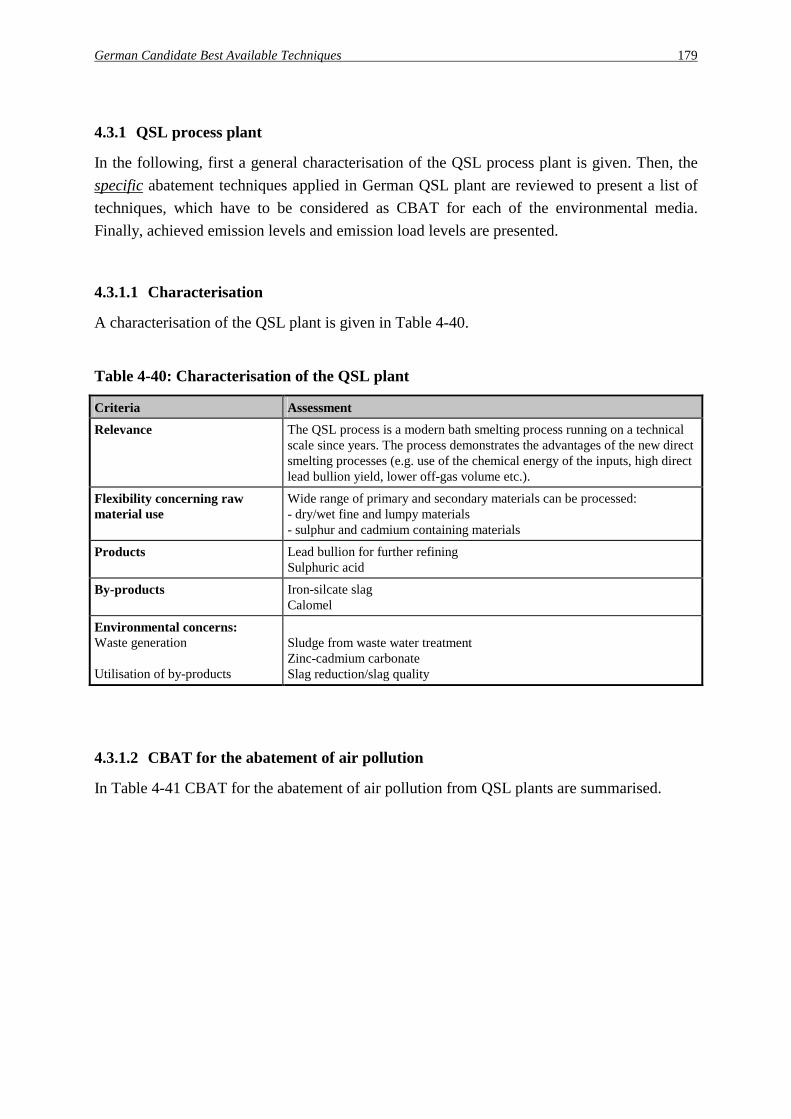
German Candidate Best Available Techniques 179
4.3.1 QSL process plant
In the following, first a general characterisation of the QSL process plant is given. Then, the specific abatement techniques applied in German QSL plant are reviewed to present a list of techniques, which have to be considered as CBAT for each of the environmental media. Finally, achieved emission levels and emission load levels are presented.
4.3.1.1 Characterisation
A characterisation of the QSL plant is given in Table 4-40.
Table 4-40: Characterisation of the QSL plant
Criteria Assessment Relevance The QSL process is a modern bath smelting process running on a technical
scale since years. The process demonstrates the advantages of the new direct smelting processes (e.g. use of the chemical energy of the inputs, high direct lead bullion yield, lower off-gas volume etc.).
Flexibility concerning raw material use
Wide range of primary and secondary materials can be processed: - dry/wet fine and lumpy materials - sulphur and cadmium containing materials
Products Lead bullion for further refining Sulphuric acid
By-products Iron-silcate slag Calomel
Environmental concerns: Waste generation Utilisation of by-products
Sludge from waste water treatment Zinc-cadmium carbonate Slag reduction/slag quality
4.3.1.2 CBAT for the abatement of air pollution
In Table 4-41 CBAT for the abatement of air pollution from QSL plants are summarised.

180 German Candidate Best Available Techniques
Table 4-41: CBAT for the abatement of air pollution
No. Abatement techniques Assessment (Effects, applicability, ...) Process unit(s): Raw materials/handling/preparation a1 Hoods Capturing of emissions, prevention of fugitive
emissions
a2 Bag filters Off-gas dedusting
Process unit(s): QSL reactor/Gas cleaning system b1 Process gas cleaning with cooling.
hot ESP and wet ESP Off-gas dedusting
b2 Further off-gas cleaning (Boliden/Norzink process) Precipitation of gaseous mercury
b3 Further off-gas processing in a sulphuric acid plant Recovery of sulphur
b4 Hoods and complete enclosement of the lead bullion/slag outlet
Collection of emissions, prevention of fugitive emissions
b5 Bag filter for exhaust gas cleaning Final gas cleaning
Process unit(s): Sulphuric acid plant d1 Double absorption contact plant Conversion of SO2 with an efficiency of more
than 99.6%
Process unit(s): Slag treatment d1 Hoods Capturing of emissions, prevention of fugitive
emissions
d2 Wet ESP Final gas cleaning
Process unit(s): Cadmium leaching plant e1 Acidic leaching Leaching of Cadmium and Chlorides to limit a
recirculation to the process
Process unit(s): Refinery Lead refining plant (c.f. 4.3.5)
4.3.1.3 CBAT for the reduction of water consumption and the control and treatment of waste water
In Table 4-42 CBAT for the reduction of water consumption and the control and treatment of waste water are summarised.
Table 4-42: CBAT for reduction of water consumption and treatment of waste water
No. Techniques Assessment (Effects, applicability, ...) w1 Use of a central waste water treatment plant The water treatment scheme is described in 4.1.
w2 Internal use of process water Reduction of fresh water consumption and effluent generation
w3 Recirculation of cooling water Reduction of fresh water consumption

German Candidate Best Available Techniques 181
4.3.1.4 CBAT for the recycling of solid materials, waste prevention and the handling of waste
In Table 4-43 main techniques for the recycling of solid materials, waste prevention and the handling of waste are summarised.
Table 4-43: CBAT for the recycling of solid materials, waste prevention and handling of waste
No. Techniques Assessment (Effects, applicability, ...) s1 Granulation of slag Granulated slag can be used in different options
s2 Leaching of flue dusts Precipitation of cadmium and recovery as cadmium carbonate
s3 Internal recirculation of the leaching residue Recovery of lead
s4 Decopperizing of lead bullion Separation of copper for later recovery
s5 Recovery of mercury from roast gas Production of Calomel, but the market for Calomel is limited
4.3.1.5 CBAT for the reduction of energy consumption
In Table 4-44 CBAT for the reduction of energy consumption are summarised.
Table 4-44: CBAT for the reduction of energy consumption and heat recovery
No. Techniques Assessment (Effects, applicability, ...) h1 Waste heat boiler for heat recovery from the
furnace off-gas Steam generation
h2 Generation of electrical energy Electrical energy is used for internal plant consumption.
4.3.1.6 Achieved emissions levels in QSL process plants
In Table 4-45, achieved emission levels and emissions load levels for the German QSL plant are listed.

182 German Candidate Best Available Techniques
Table 4-45: Achieved emission levels for controlled emissions into the atmosphere (main sources)
Process unit
Emission level [mg/Nm³]
Off-gas volume [Nm³/h] / [Nm³/t Pb]
Emission load level [g/t Pb]
Raw material storage, handling, refinery
Dust: Pb: Cd:
NOx: SO2:
1 - 2 0.2 - 1 0.005 - 0.05 10 - 20*) 5 - 200*)
220,000 / 20,000 Dust: Pb: Cd:
NOx: SO2:
20 - 40 4 - 20 0.1 - 1 200 - 400*) < 600*)
Sulphuric acid plant Dust: Pb: Cd:
NOx: SO2
< 1 0.001 - 0.02 0.001 - 0.002250 - 400 200 - 300
20,000 / 1,900 Dust: Pb: Cd:
NOx: SO2: SO3:
< 2 < 0.1 < 0.01 500 - 750 400 - 600 200
Slag granulation Dust: Pb: Cd:
NOx: SO2:
1 - 5 0.5 - 2 < 0.001 < 10 < 20
190 / 20 Dust: Pb: Cd:
NOx: SO2:
0.02 - 0.1 traces traces < 0.2 traces
*) The SO2 and NOx emissions arise during the refining operations.
In Table 4-46, achieved emissions levels for waste water discharges are summarised. A typical of a QSL plant is about 10 m³/h.
Table 4-46: Achieved emission levels for waste water discharges
Element
Emission level [mg/l]
Load level [g/t lead]
Element Emission level [mg/l]
Load level [g/t lead]
Cu 0.01 < 0.01 As < 0.05 < 0.05
Pb 0.2 < 0.18 Ni < 0.05 < 0.05
Zn 0.3 < 0.27 Cr < 0.05 < 0.05
Cd < 0.05 < 0.05 Sulphide < 0.1 < 0.09
Hg < 0.001 < 0.001 AOX < 0.1 < 0.09

German Candidate Best Available Techniques 183
4.3.2 Sirosmelt plant
4.3.2.1 Characterisation
A characterisation of the Sirosmelt plant is given in Table 4-47.
Table 4-47: Characterisation of the Sirosmelt plant
Criteria Assessment Relevance Since the beginning of the second quarter 1996, one Sirosmelt plant is
operating in Germany on a technical scale. The process demonstrates the advantages of the new direct smelting processes (e.g. use of the chemical energy of the inputs, high direct lead bullion yield, lower off-gas volume etc.).
Flexibility concerning raw materials
A wide range of primary and secondary dry or wet material in fine or defined lumpy form can be processed.
Products Lead bullion for further refining Sulphuric acid
By-products Granulated slag as iron silicate slag. Mercury residue for recycling in another smelter
Environmental concerns: Utilisation of by-products Waste generation
Slag reduction Sludges from waste water treatment
4.3.2.2 CBAT for the abatement of air pollution
In Table 4-48 CBAT for the abatement of air pollution from the Sirosmelt plant are summarised.

184 German Candidate Best Available Techniques
Table 4-48: CBAT for the abatement of air pollution
No. Abatement techniques Assessment (Effects, applicability, ...) Process unit(s): Raw materials/handling/preparation a1 Total enclosed storage, hoods, closed conveyors Capturing of emissions, prevention of fugitive
emissions
a2 Bag filters Off-gas dedusting
Process unit(s): QSL reactor/Gas cleaning system b1 Process gas cleaning with cooling.
hot ESP and wet ESP Off-gas dedusting
b2 Further off-gas cleaning (Boliden/Norzink process) Recovery of sulphur
b3 Further off-gas processing in a sulphuric acid plant Capturing of emissions, prevention of fugitive emissions
b4 Hoods and complete enclosement of the lead bullion/slag outlet
Final off-gas cleaning
b5 High vacuum dedusting unit Prevention of fugitive emissions
Process unit(s): Sulphuric acid plant d1 Double absorption contact plant Conversion of SO2 with an efficiency of more
than 99.6%
d2 Boliden Chemie Process for mercury removal Precipitation of mercury
Process unit(s): Slag treatment d1 Hoods Capturing of emissions, prevention of fugitive
emissions
d2 Wet ESP Final gas cleaning
Process unit(s): Cadmium leaching plant e1 Acidic leaching Separation of Chlorine and Cadmium and
precipitation of CdCO3
Process unit(s): Refinery Lead refining plant (c.f. 4.3.5)
4.3.2.3 CBAT for the reduction of water consumption and the control and treatment of waste water
In Table 4-49 CBAT for the reduction of water consumption and the control and treatment of waste water are summarised.
Table 4-49: CBAT for the reduction of water consumption and treatment of waste water
No. Techniques Assessment (Effects, applicability, ...) w1 Waste water treatment in a central waste water
treatment plant The water treatment scheme is described in 4.1.
w2 Internal use of rain and process water Reduction of fresh water consumption and waste water
w3 Recirculation of cooling water Reduction of cooling water and energy input to the river

German Candidate Best Available Techniques 185
4.3.2.4 CBAT for the recycling of solid materials, waste prevention and the handling of waste
In Table 4-50 CBAT for the recycling of solid materials, waste prevention and the handling of waste are summarised.
Table 4-50: CBAT for the recycling of solid materials, waste prevention and handling of waste
No. Techniques Assessment (Effects, applicability, ...) s1 Granulation of slag Granulated slag can be used in different options
s2 Internal recirculation of the main part of the flue dust
Recovery of lead
s3 Internal leaching of remaining flue dust Separation of chlorine and cadmium and precipitation of cadmium carbonate
s4 Internal recirculation of leaching residue Recovery of lead
s5 Decopperizing of lead bullion Recovery of copper bearing products for further treatment
s6 Recovery of mercury from sulphuric acid Production of mercury sludge for further treatment and Calomel production in the zinc plant
4.3.2.5 CBAT for the reduction of energy consumption
In Table 4-51 CBAT for the reduction of energy consumption are summarised.
Table 4-51: CBAT for the reduction of energy consumption and heat recovery
No. Techniques Assessment (Effects, applicability, ...) h1 Waste heat boiler for heat recovery of heat from
furnace off-gas Steam generation for heating and supplying of drives
h2 Oxygen enrichment of blast Energy reduction for smelting
4.3.2.6 Achieved emissions levels in the Sirosmelt plant
In Table 4-52, emission levels and emissions load levels which are achieved in the actual realisation stage of the Sirosmelt plant are listed.

186 German Candidate Best Available Techniques
Table 4-52: Achieved emission levels for controlled emissions into the atmosphere (main sources)
Process unit
Emission level*) [mg/Nm³]
Off-gas volume [Nm³/h] / [Nm³/t Pb]
Emission load level [g/t Pb]
Raw material storage / handling
Dust: Pb: Cd:
0.002 - 0.068 < 0.001 - 0.030 << 0.001
118,000 / 10,500 Dust: Pb: Cd:
0.14 0.05 < 0.001
Sulphuric acid plant NOx: SO2:
2.5 - 15.0 300 - 700
35,000 / 3,100 NOx: SO2:
30 1,560
Slag granulation / furnace area / decopperizing
Dust: Pb: Cd:
SO2:
0.18 - 3.6 0.1 - 2.2 << 0.001 - 0.01740 - 600
110,000 / 9,800 Dust: Pb: Cd: SO2
9.6 5.9 0.03 3,150
Refinery (c.f. 4.3.5) Dust: Pb: Cd:
NOx:
0.001 - 0.15 < 0.001 - 0.11 Traces Traces
66,000 / 5,900 Dust: Pb: Cd:
NOx:
0.3 0.1 << 0.001 Traces
*) To guarantee, that the emission limit values can be kept, the mentioned emission level has to be about 3 - 10 times lower than the emission limit value.
In Table 4-53, achieved emissions levels for waste water discharges are summarised.
Table 4-53: Achieved emission levels for waste water discharges
Element
Emission level*) [mg/l]
Load level [g/t lead]
Element Emission level*)
[mg/l] Load level [g/t lead]
Cu n. a. n. a. As < 0.001 - 0.1 < 0.03
Pb 0.01 - 0.5 < 0.02 Ni n. a. n. a.
Zn 0.01 - 0.4 < 0.04 Cr n. a. n. a.
Cd < 0.005 < 0.001 Sulphide < 0.001 - 0.01 < 0.01
Hg < 0.001 < 0.001 AOX 0.004 - 0.13 < 0.04 *) To guarantee, that the emission limit values can be kept, the mentioned emission level has to be about 10 times lower than the emission limit value (c.f. Chapter 4.3 ).

German Candidate Best Available Techniques 187
4.3.3 Shaft furnace plants for battery recycling
In the following, first a general characterisation of the shaft furnace plant for battery recycling is given. Then, the specific abatement techniques applied in the German shaft furnace plant are reviewed to present a list of techniques, which have to be considered as CBAT for each of the environmental media. Finally, achieved emission levels and emission load levels are presented.
4.3.3.1 Characterisation
A characterisation of the shaft furnace process plants is given in Table 4-54.
Table 4-54: Characterisation of the shaft furnace process plants
Criteria Assessment Relevance About 4 plants are operated in the EU.
Flexibility concerning raw material use
Battery scrap is the main input material; to a certain extent other lead bearing materials can be processed.
Products Lead bullion for further refining
By-products Iron silicate slag Iron/lead matte
Environmental concerns: Waste generation Emissions into the atmosphere
Flue dusts with high clorine content Control of SO2-emissions in the furnace off-gas
4.3.3.2 CBAT for the abatement of air pollution
In Table 4-55 CBAT for the abatement of air pollution from shaft furnace plants are summarised.

188 German Candidate Best Available Techniques
Table 4-55: CBAT for the abatement of air pollution
No. Techniques Assessment (Effects, applicability, ...) Process unit(s): Raw materials handling a1 Moistening of raw materials Prevention of fugitive emissions
a2 Indoor storage or storage under a roof Prevention of fugitive emissions
a3 Removal of parts of the waste acid Reduction of sulphur content of the inputs
Process unit(s): Shaft furnace/gas cleaning b1 Secondary hoods at the tapping area Collection of fugitive emissions
b2 Gas cleaning system with post combustion chamber (minimum: 850°C, typically: 1,100°C), dry quenching with secondary off-gases fabric filter
Removal of hydrocarbons and dust
b3 Oxygen enrichment of process air Reduction of off-gas volume and generation of flue dusts
b4 Injection of calcium hydroxide, if necessary Prevention of sulphur dioxide emissions peaks
Process unit(s): Refinery Lead refining plant (c.f. 4.3.5)
4.3.3.3 CBAT for the reduction of water consumption and the control and treatment of waste water
In Table 4-56 CBAT for the reduction of water consumption and the control and treatment of waste water are summarised.
Table 4-56: CBAT for the reduction of water consumption and treatment of waste water
No. Techniques Assessment (Effects, applicability, ...) w1 Adequate waste water treatment The water treatment scheme is described in 4.1.
w2 Internal use of treated water Reduction of fresh water consumption and effluent generation
w3 Recirculation of shaft furnace cooling water Reduction of fresh water consumption
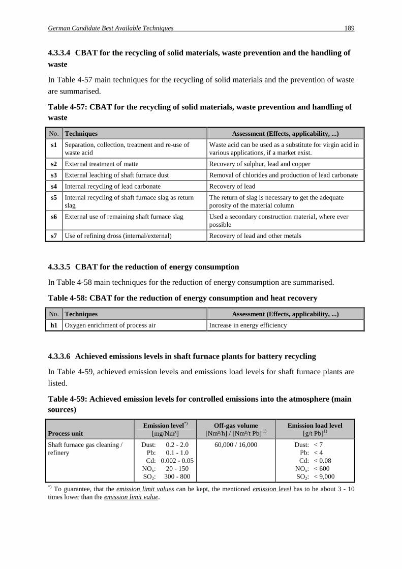
German Candidate Best Available Techniques 189
4.3.3.4 CBAT for the recycling of solid materials, waste prevention and the handling of waste
In Table 4-57 main techniques for the recycling of solid materials and the prevention of waste are summarised.
Table 4-57: CBAT for the recycling of solid materials, waste prevention and handling of waste
No. Techniques Assessment (Effects, applicability, ...) s1 Separation, collection, treatment and re-use of
waste acid Waste acid can be used as a substitute for virgin acid in various applications, if a market exist.
s2 External treatment of matte Recovery of sulphur, lead and copper
s3 External leaching of shaft furnace dust Removal of chlorides and production of lead carbonate
s4 Internal recycling of lead carbonate Recovery of lead
s5 Internal recycling of shaft furnace slag as return slag
The return of slag is necessary to get the adequate porosity of the material column
s6 External use of remaining shaft furnace slag Used a secondary construction material, where ever possible
s7 Use of refining dross (internal/external) Recovery of lead and other metals
4.3.3.5 CBAT for the reduction of energy consumption
In Table 4-58 main techniques for the reduction of energy consumption are summarised.
Table 4-58: CBAT for the reduction of energy consumption and heat recovery
No. Techniques Assessment (Effects, applicability, ...) h1 Oxygen enrichment of process air Increase in energy efficiency
4.3.3.6 Achieved emissions levels in shaft furnace plants for battery recycling
In Table 4-59, achieved emission levels and emissions load levels for shaft furnace plants are listed.
Table 4-59: Achieved emission levels for controlled emissions into the atmosphere (main sources)
Process unit
Emission level*) [mg/Nm³]
Off-gas volume [Nm³/h] / [Nm³/t Pb] 1)
Emission load level [g/t Pb]1)
Shaft furnace gas cleaning / refinery
Dust: Pb: Cd:
NOx: SO2:
0.2 - 2.0 0.1 - 1.0
0.002 - 0.05 20 - 150
300 - 800
60,000 / 16,000 Dust: Pb: Cd:
NOx: SO2:
< 7 < 4 < 0.08 < 600 < 9,000
*) To guarantee, that the emission limit values can be kept, the mentioned emission level has to be about 3 - 10 times lower than the emission limit value.

190 German Candidate Best Available Techniques
In Table 4-60, achieved emissions levels for waste water discharges from shaft furnace plants are summarised. A typical shaft furnace plant has a waste water flow of about 2 m³/h.
Table 4-60: Achieved emission levels for waste water discharges
Element
Emission level*) [mg/l]
Load level [g/t lead]
Element Emission level*)
[mg/l] Load level [g/t lead]
Cu 0.01 - 0.05 < 0.01 As 0.001 - 0.01 < 0.001
Pb 0.05 - 0.5 < 0.08 Ni 0.02 - 0.2 < 0.05
Zn 0.05 - 0.8 < 0.10 Cr 0.005 - 0.05 < 0.006
Cd 0.01 - 0.15 < 0.05 Sulphide 0.005 - 0.1 < 0.006
Hg < 0.001 << 0.001 *) To guarantee, that the emission limit values can be kept, the mentioned emission level has to be about 10 times lower than the emission limit value (c.f. Chapter 4.3).

German Candidate Best Available Techniques 191
4.3.4 Rotary furnace plants (MA or CX technology)
As the use of modern separation technologies avoids the burning of plastics (PVC, ebonite) and allows a recovery of polypropylene, only rotary furnace applying these techniques (MA or CX technology) are investigated further. Furthermore, the following processing types for rotary furnace plants have to be distinguished: a) Smelting of grid metal / external treatment of paste (type A) b) Paste desulphurisation / smelting of grid metal and paste / sodium sulphate production (type B) In the following, first a general characterisation of the rotary furnace plants is given. Then, the specific abatement techniques applied in German rotary furnace plants are reviewed to present a list of techniques, which have to be considered as CBAT for each of the environmental media. Finally, achieved emission levels and emission load levels are presented.
4.3.4.1 Characterisation
A characterisation of the rotary furnace plants (MA or CX technology) is given in Table 4-61.
Table 4-61: Characterisation of the rotary furnace plants (MA or CX technology)
Criteria Assessment Relevance The short rotary furnace is the most often used device for secondary lead
production in the EU. Modern plant technology allows the recovery of polypropylene; the separated paste can be processed externally (type A) or internally (type B).
Flexibility concerning raw material use
Besides battery scrap as main input material, other lead bearing secondary materials are processed.
Products Type A: Lead bullion for further refining Polypropyelene
Type B: Lead bullion for further refining Polypropylene Sodium sulphate
By-products Paste
Environmental concerns: Waste generation
Slag Plastic waste
Slag Plastic waste
4.3.4.2 CBAT for the abatement of air pollution
In Table 4-62 CBAT for the abatement of air pollution from rotary furnace plants (MA or CX technology) are summarised.

192 German Candidate Best Available Techniques
Table 4-62: CBAT for the abatement of air pollution
No. Techniques Assessment (Effects, applicability, ...) Process unit(s): Raw materials handling/battery treatment a1 Indoor storage or storage under a roof (Type A+B) Prevention of fugitive emissions
Process unit(s): Rotary furnace/gas cleaning system b1 Furnace encapsulation (Type A+B) Prevention of emissions
b2 Fabric filter for off-gas cleaning (Type A+B) Dedusting
Process unit(s): Refinery Lead refining plant (c.f. 4.3.5)
4.3.4.3 CBAT for the reduction of water consumption and the control and treatment of waste water
In Table 4-63 CBAT for the reduction of water consumption and the control and treatment of waste water are summarised.
Table 4-63: CBAT for the reduction of water consumption and treatment of waste water
No. Techniques Assessment (Effects, applicability, ...) w1 Adequate waste water treatment (Type A+B) The water treatment scheme is described in 4.1.
w2 Recirculation of process water from hydroseparation (Type A+B)
Reduction of fresh water consumption
4.3.4.4 CBAT for the recycling of solid materials, waste prevention and the handling of waste
In Table 4-64 main techniques for the recycling of solid materials, waste prevention and the handling of waste are summarised.

German Candidate Best Available Techniques 193
Table 4-64: CBAT for the recycling of solid materials, waste prevention and handling of waste
No. Techniques Assessment (Effects, applicability, ...) s1 Separation of ebonite, PVC and polypropylene
(Type A + B) Recovery of polypropylene chips as by-product Use of residual for energy recovery Prevention of chloride input from PVC to the metallurgical process Prevention of sulphur input from ebonite to the metallurgical process
s2 Collection and (internal) treatment of waste acid (Type A + B)
-
s3 Agglomeration and recycling of flue dust (Type A + B)
Minimisation of dust handling Internal treatment for lead recovery
s4 Compoundation of polypropylene (Type A + B)
Production of a marketable product
s5 Desulphurisation of paste (Type B) Production of water free sodium sulphate as by-product Internal recycling of desulphurised paste
s6 External recycling of battery paste (Type A) Recovery of lead and sulphur if the paste is processed in a modern lead smelting plant
s7 Internal recycling of sludges from waste water treatment (Type A + B)
Recovery of lead
4.3.4.5 CBAT for the reduction of energy consumption
In Table 4-65 main techniques for the reduction of energy consumption are summarised.
Table 4-65: CBAT for the reduction of energy consumption and heat recovery
No. Techniques Assessment (Effects, applicability, ...) h1 Separation of plastic materials (Type A + B) Recovery of polypropylene with an energetic value of
3,000 MJ/t Pb Recovery of other plastics with an energetic value of 3,000 MJ/t Pb
h2 Waste heat recovery (furnace off-gas) (Type A+B) Steam generation for internal use
4.3.4.6 Achieved emissions levels in rotary furnace plants (MA or CX technology)
In Table 4-66, achieved emission levels and emissions load levels for both types of rotary furnace plants are listed.

194 German Candidate Best Available Techniques
Table 4-66: Achieved emission levels for controlled emissions into the atmosphere (main sources)
Process unit
Emission level[mg/Nm³]
Off-gas volume [Nm³/h] / [Nm³/t Pb] *)
Emission load level [g/t Pb]*)
Rotary furnace (Type A + B) / refinery
Dust: Pb: Cd
NOx: SO2:
0.5 - 4 0.2 - 1 < 0.0055 - 20 50 - 150
150,000 - 250,000 / 30,000 - 45,000
Dust: Pb: Cd
NOx: SO2:
15 - 80 5 - 25 < 0.2 200 - 500 2,500 - 4,000
*) per tonne lead / lead bullion produced
In Table 4-67, achieved emissions levels for waste water discharges from rotary furnace plants are summarised. The given values are valid for both types of plants. The range for typical discharge flows is 12.5 - 25 m³/h (or 3.5 - 4.5 m³/t Pb).
Table 4-67: Achieved emission levels for waste water discharges
Element
Emission level [mg/l]
Load level [g/t Pb]
Element Emission level [mg/l]
Load level [g/t Pb]
Cu 0.01 < 0.05 As 0.07 < 0.3
Pb 0.12 - 0.2 0.4 - 0.7 Ni < 0.1 < 0.4
Zn 0.2 < 0.7 Cr < 0.05 < 0.2
Cd 0.05 < 0.2 Sulphide < 0.2 < 0.7
Hg < 0.001 << 0.01 AOX 0.06 - 0.2 0.2 - 0.7

German Candidate Best Available Techniques 195
4.3.5 Lead refining plants
In the following, first a general characterisation of lead refining plants is given. Then, the specific abatement techniques applied in German lead refineries are reviewed to present a list of techniques, which have to be considered as CBAT for each of the environmental media. Finally, achieved emission levels and emission load levels are presented.
4.3.5.1 Characterisation
A characterisation of the lead refining plants is given in Table 4-68.
Table 4-68: Characterisation of the lead refining plants
Criteria Assessment Relevance Lead refining is necessary for the production of marketable lead alloys and
soft lead quantities
Flexibility concerning raw material use
The selection of raw materials depends on the product specifications and the refining equipment of the individual plant.
Products Refined lead Lead alloys (e.g. PbSb, PbCa, PbSn, ...)
By-products Drosses, skimmings, silver/bismuth crusts, ...
Environmental concerns: -
4.3.5.2 CBAT for lead refining plants
In Table 4-69 CBAT for lead refining plants are summarised.
Table 4-69: CBAT for lead refining plants
No. Techniques Assessment (Effects, applicability, ...) CBAT for the abatement of air pollution
a1 Ventilation/hood system for refining kettles Capturing of emissions
a2 Fabric filters for exhaust gas cleaning Dedusting
a3 Skimming machines for removal of drosses and slags Prevention of fugitive emissions
CBAT for the recycling of solid materials, waste prevention and the handling of waste s1 Internal or external recycling of dross, crusts Waste minimisation and metal recovery
Achieved emission levels and emissions load levels for lead refining plants have already been included in the different sections of Chapter 4.3 dealing with the production process plants.

196 German Candidate Best Available Techniques

Emerging techniques, future trends 197
5 Emerging techniques, future trends
In this chapter, a collection of so-called emerging techniques and future trends is presented. According to the discussions with the national experts, the described processes may be seen as relevant for the further development in Germany.
BSN process for the recycling of EAF-dusts23 The BSN process can be used for recovery of zinc and lead from metallurgical-works dust. A schematic view of the process is shown in figure 6-1. BSN GmbH plans to erect a 25,000 t/a plant, using the self developed BSN process, for the treatment of its EAF dusts. Main components of this plant are three rotary kilns operated within different temperature intervals (300 - 600°C, 1,000 - 1,100°C, 1,150 - 1,200°C). Products of this residue free process are zinc oxide, alkali/lead-chloride, and iron pellets.
Alkali / lead-chloride compounds (Product 3)
Dust pellets (dried, preheated)
Pellets
Iron fraction (Product 1)
EAF dust (pelletized)
Coal
Hot Air
Hot AirOff-gas
Zinc oxide (Product 2)
Cooling Filtering
Flue gasCooling Filtering
Rotary kiln 3 (zinc removal) 1,150 - 1,200°C
Rotary kiln 2 (lead removal) 1,000 - 1,100°C
Rotary kiln 1 (preheating, drying) 300 - 600°C
Figure 5-1: Schematic view of the BSN process for treatment of EAF dusts
Source: following Klein et al. [39]
The operation of an industrial processing plant with a capacity of 8,000 t/a has started in November 1998.
23 Badische Stahl-Nebenprodukte GmbH, Kehl (Germany)

198 Emerging techniques, future trends
EZINEX process for the treatment of secondary zinc-containing materials The EZINEX process has been developed for the on-site recovery of zinc from EAF-dusts. In Udine (Italy), the first plant on an industrial scale is in operation. It has a treatment capacity of 12,000 t/a resulting in an annual production of 2,000 t zinc cathodes [64]. The main aggregates are the leaching tanks, the filter, the cementation tanks, and the electrolysis cells. In the first process step, the zinc containing inputs are fed to the leaching reactor and dissolved in spent electrolyte based on ammonium and alkali chloride. Besides iron most of the heavy metals are dissolved in form of their ammine complexes. The remaining residue containing iron oxides, zinc ferrite and silica is separated by press-filtration and dried. After pelletisation with coke, it can be recycled, for example to the EAF. The solution is further purified by cementation of copper, lead and cadmium under addition of zinc powder. The recovered precipitate is sent to a lead smelting plant for further recycling. The purified solution is led to the electrolysis cells where zinc is reduced by means of titanium cathodes. The formation of Cl2 at the graphite anodes can be avoided because of the reaction of chlorine with NH4OH to HCl and nitrogen. As a consequence, an equivalent amount of NH3 is added to the electrolysis cells. In case of an insufficient purification other heavy metals are co-deposited. During the leaching step alkali chlorides, fluorides and most of the sulphates are dissolved, too. To avoid an accumulation of these substances, a share of the electrolyte has to be evaporated for the crystallisation of chlorides and sulphates. According to [47], the EZINEX process may be more suited for the treatment of secondary materials with a higher zinc content than EAF-dust, which are not usable for conventional zinc electrolysis plants. As a consequence, the amount of residues, which is produced in the EZINEX process, can be reduced. A schematic flowsheet of the modified EZINEX process is shown in Figure 5-2.
Zn powder
FiltrationCementation
Filtration
Leaching
Zinc-containingInputs
Cementates
NH3 N2
Electrolysis
Zn cathodes
Spent electrolyte
+ -
Iron-containing residue
Figure 5-2: Schematic flowsheet of the EZINEX process

References 199
6 References
[1] 2. Allgemeine Verwaltungsvorschrift zum Abfallgesetz (TA Abfall, Teil 1: Technische Anleitung zur Lagerung, chemisch/physikalischen und biologische Behandlung und Verbrennung von besonders überwachungsbedürftigen Abfällen) vom 12. März, in: GMBl, p. 169, 1990
[2] 3. Allgemeine Verwaltungsvorschrift zum Abfallgesetz (TA Siedlungsabfall, Technische Anleitung zur Verwertung, Behandlung und sonstigen Entsorgung von Siedlungsabfällen) Bekanntmachung des Bundesumweltministeriums vom 14. Mai 1993, in: BAnz Nr. 99a vom 29. Mai 1993
[3] 1. Allgemeine Verwaltungsvorschrift zum Bundesimmissionsschutzgesetz (Technische Anleitung zur Reinhaltung der Luft – TA Luft) vom 27. Februar 1986, in: GMBl, p. 95, 1986
[4] Allgemeine Verwaltungsvorschrift über genehmigungsbedürftige Anlagen nach § 16 der Gewerbe-ordnung (TA Lärm: Technische Anleitung zum Schutz gegen Lärm, Beilage), in: BAnz Nr. 137 vom 26. Juli 1968, as at 1994
[5] Basel Convention on the Control of Transboundary Movements of Hazardous Waste and their Disposal, published in Official Journal of the European Community, 16. February 1993
[6] Behrendt, H.P.; Steil, H.-U.: Modernisierung der Sekundärbleihütte und der Verbrennungsanlage der Muldenhütten Recycling und Umwelttechnik GmbH, Freiberg, Erzmetall 50, Nr.6, Clausthal-Zfd., 1997
[7] Behrendt, H.P.; Steil, H.-U.: Lead-Acid Batteries: State of Environmentally Sound Recovery and Recycling, in: Congress Proceedings R´97 Recovery, Recycling , Re-integration, Vol. 1, Geneva (Switzerland), 4-7 February, 1997
[8] Benz; Birle; Günther; Ulbrich: Umweltschutzanforderungen in der Metallindustrie, 3rd edition, Verband Deutscher Maschinen- und Anlagenbau e.V. (VDMA), Frankfurt/M., (1995)
[9] "Berzelius" Metall GmbH (ed.): "Berzelius" Metall GmbH, Firmeninformation, Braubach
[10] Bundesamt für Wirtschaft: Erhebungsergebnisse der NE-Metallfachstatistik, Berichtsjahr 1995, Teil II, Eschborn (Germany)
[11] Bundesamt für Wirtschaft: Erhebungsergebnisse der NE-Metallfachstatistik, Berichtsjahr 1996, Teil I, Eschborn (Germany)
[12] Bundesimmissionsschutzgesetz (BimSchG) mit Durchführungsverordnungen sowie TA Luft und TA Lärm, 6. Auflage, Deutscher Fachschriftenverlag, Wiesbaden, 1988
[13] Bundesminister für Umwelt, Naturschutz und Reaktorsicherheit und Länderarbeitsgemeinschaft Wasser (eds.): Mindestanforderungen an das Einleiten von Abwasser in Gewässer (§ 7a WHG) Nichteisen-metallherstellung - Hinweise und Erläuterungen zu Anhang 39 der Rahmen-Abwasser VwV, Bundes-anzeiger Verlag, Köln, 1993
[14] Burgert, P.: Dezincing galvanised-steel scrap, in: New Steel, 2/1997, p.62-63
[15] Council of European Communities (CEC) (1975): Council Directive on Waste (75/464/EEC), Official Journal L194/39, 25 July 1975
[16] Council of European Communities (CEC) (1991a): Amendment to Council Directive on Waste (75/464/EEC), Official Journal L78/32, 26 March 1991
[17] Council of European Communities (CEC) (1991c): Council Directive amending Council Directive (75/464/EEC) on Waste (91/689/EEC), Official Journal L78/32, 26 March 1991
[18] Davids, P.; Lange, M.: Die TA Luft '86 - Technischer Kommentar, VDI Verlag, Düsseldorf, 1986
[19] Deininger, L. E.: Das QSL-Verfahren im großtechnischen Einsatz - Erfahrungen mit einer integrierten Technologie, in: Umweltbundesamt Texte 39/93, Berlin, 1993
[20] Deininger, L. E.; Höhn, R.W.: Emissionsminderung einer Bleihütte durch Ersatz der Sinter- und Schachtofenanlage mit einem QSL-Reaktor, Band I + II, Programm des Bundesministers für Umwelt-schutz, Naturschutz und Reaktorsicherheit, Luftreinhaltung, Nr.3050, Bonn, Oktober 1993
[21] Díaz, G.; Andrews, D.: Placid - a clean process for recycling lead from batteries, JOM, TMS, W d l (USA) J 1996

200 References
Warrendale (USA), January 1996
[22] DIN EN 1948: Emissionen aus stationären Quellen - Bestimmung der Massenkonzentration von PCDD/PCDF
[23] European Commission, DG XI (Ed.): Study on technical and economic aspects of measures to reduce (on the basis of BAT) the pollution of water and other environmental areas from the non-ferrous metal industry, Report Nr. CO 3400/1, September 1993
[24] GDMB Gesellschaft Deuscher Metallhütten- und Bergleute e.V. (eds.): Abfallstoffe in der Nichteisen-Metallurgie - Wiederverwertung oder Deponie?, VCH Verlagsgesellschaft, Weinheim, 1986
[25] Gesetz über Abgaben für das Einleiten von Abwasser in Gewässer (Abwasserabgabengesetz - AbwAG) in der Fassung der Bekanntmachung vom 3. November 1994, in: BGBl I, p. 3370, (1994)
[26] Gesetz zur Förderung der Kreislaufwirtschaft und Sicherung der umweltverträglichen Beseitigung von Abfällen (Kreislaufwirtschafts- und Abfallgesetz – KrW-/AbfG) vom 27. September 1994, in: Bundes-gesetzblatt BGBl I, Bonn, p. 2705, (1994)
[27] Gesetz zur Ordnung des Wasserhaushalts (Wasserhaushaltsgesetz - WHG) vom 27. Juli 1957, in der Neufassung vom 12. November 1996, in: Bundesgesetzblatt BGBl I, p.1696, Bundesanzeiger Verlag, Köln
[28] Gesetz zur Vermeidung, Verwertung und Beseitigung von Abfällen vom 27.9.1994, in Bundesgesetzblatt BGBl I, Bonn, p.2705 (1994)
[29] Graf, G.G.: Zinc in Ullmann´s Encyclopedia of Industrial Chemistry, Vol. A 28, VCH Verlagsgesell-schaft, Weinheim, pp. 509 - 543, 1996
[30] Her Majesty´s Inspectorate of Pollution (ed.): Chief Inspector´s Guidance to Inspectors - Processes for the Production of Zinc and Zinc Alloys, London, 1994
[31] Hoffmann, M.: Die Rückgewinnung von Zink und Blei aus Stäuben der Elektrostahlerzeugung, in: VDI-Seminar Verwertung durch Einschmelzen, Sekundärmetallgewinnung und Energienutzung bei der thermischen Behandlung von Abfällen, Düsseldorf, 22./23.9.1997
[32] Hoffmann, M.: Recovery of Zinc and Lead from Electric Arc Furnace Steel Dust, in: Congress Procee-dings R´97, Recovery, Recycling , Re-integration, Vol. 5, Geneva (Switzerland), 4-7 February, 1997
[33] International Lead and Zinc Study Group (ed.): Lead and Zinc Statistics, Brussels, dated 6. 1998
[34] International Zinc Association (ed.): Pocket Guide to World Zinc, Brussels, 1996
[35] Jockel, W; Hartje, J.: Die Entwicklung der Schwermetallemissionen in der Bundesrepublik Deutschland von 1985 bis 1995, unpublished research report, UBA no. 94-104 03 524, Berlin, 1995
[36] Jolly, R.; Rhin, C,: The recycling of lead-acid batteries: production of lead and polypropylene, Resources, Conservation and Recycling , 10 p. 137-143, 1994
[37] Karpel, S.: Greater Flexibility and Lower Costs at Nordenham, Metal Bulletin Monthly, December 1998, p. 40-45
[38] Kéri, J.; Precskó, J.: Development and use of a new system for environmentally clean recycling of lead battery scrap, Journal of Power Sources, 53, p. 297-302, 1995
[39] Klein, K.H.; Discher, H.P.; Haase, K.: The BSN process to recycle zinc and lead fume dust, UN/ECE-Seminar on Economic Aspects of Clean Technologies, Energy and Waste Management in the Steel Industry, Linz, 22.-24.4.1998
[40] Klotz, P.: Umweltverträgliche Bleigewinnung, Metall 50. Jg. Nr. 10, p. 643-648, Heidelberg, 1996
[41] Klotz, P.: Umweltverträgliche Bleigewinnung, Proceedings Utech-Seminar Integrierter Umweltschutz in der metallerzeugenden Industrie, Berlin, 1996

References 201
[42] Kola, R.; Estel, R.; Steil, H.-U.: Abscheidung bleihaltiger Stäube mit einem Ionisationswäscher, Abschlußbericht eines Forschungsvorhaben im Rahmen des Programs Investitionen zur Verminderung von Umweltbelastungen, Bundesminister für Umwelt, Naturschutz und Reaktorsicherheit, Luftrein-haltung, Nr.1108, September 1991
[43] Kola, R.; Tack, K.; Steil, H.-U.: Staubfreie Entladung von Sekundärstoffen für die NE-Metallerzeu-gung, Abschlußbericht eines Forschungsvorhaben im Rahmen des Programs Investitionen zur Ver-minderung von Umweltbelastungen, Bundesminister für Umwelt, Naturschutz und Reaktorsicherheit, Luftreinhaltung, Nr.1104, Bonn, March 1992
[44] Kola, R.; Steil, H.-U.: Verminderung der Schwermetallemissionen einer Feinzinkanlage durch prozeß- und abscheidetechnische Maßnahmen mit Abwärmenutzung, Abschlußbericht eines Forschungsvor-haben im Rahmen des Programs Investitionen zur Verminderung von Umweltbelastungen, Bun-desminister für Umwelt, Naturschutz und Reaktorsicherheit, Luftreinhaltung, Nr.1096, January 1989
[45] Kola, R.; Steil, H.-U.: Entstaubung einer Schlackengranulation und einer Ofengicht eines Zink/Blei-Schachtofens mit einem Naß-Elektrofilter, Abschlußbericht eines Forschungsvorhaben im Rahmen des Programs Investitionen zur Verminderung von Umweltbelastungen, Bundesminister für Umwelt, Naturschutz und Reaktorsicherheit, Luftreinhaltung, Nr.1077, Bonn, Mai 1986
[46] Krol, W.; Steil, H.U.: Bestandsaufnahme internationaler Umweltschutz-Aktivitäten und deren Auswirkungen auf die deutsche NE-Metallindustrie, Metall, 51 Jg., Nr.3 (part 1, p.126 - 136) and Nr. 9 (part 2, p. 498-505), Heidelberg, 1997
[47] Krüger, J.: Personal communication, RWTH Aachen 19.1.1999
[48] Krüger, J.: Zukünftige Anforderungen an die Blei- und Zinkindustrie, Erzmetall 51, Nr.4, p.259 -265, Clausthal-Zfd., 1998
[49] Krüger, J.: Proposal for a BREF-not for Pb, Zn, Cd, Sb, Part 1&2&3, Aachen, 1998
[50] Länderausschuß für Immissionschutz (Hrsg.): Erarbeitung von Anforderungen zur Emissionsbegrenzung von Dioxinen und Furanen, Schriftenreihe des LAI, Erich Schmidt Verlag, Berlin
[51] Länderarbeitsgemeinschaft Abfall (Ed.): Zuordnung LAGA – Abfallschlüssel zum Europäischen Abfallkatalog und zu den OECD-Codes, Erich Schmidt Verlag, Berlin, (1996) (Abfallwirtschaft in Forschung und Praxis; Bd. 93)
[52] Länderarbeitsgemeinschaft Abfall (Ed.): LAGA – Informationsschrift Abfallarten, 4. durchgesehene Auflage, Erich Schmitt Verlag, Berlin, (1992) (Abfallwirtschaft in Forschung und Praxis; Bd. 41)
[53] Lamm, K.F.: Secondary Lead, Erzmetall 51, Nr. 6, S. 438 - 455, Clausthal-Zfd., 1998
[54] Lee, R.; Piasentin, M.: The Treatment of Secondary Materials in the Imperial Smelting Process, in Proceedings of Recycling Lead and Zinc into the 21st Century, Conference, 18-23 June 1995, Madrid
[55] Malorny, U.: Die Verordnungen zur Einführung des Europäischen Abfallkatalogs, zur Bestimmung von besonders überwachungsbedürftige Abfälle und zur Bestimmung von überwachungsbedürftige Abfälle zur Verwertung, in: Referatesammlung des 17. Abfallwirtschaftlichen Fachkolloquiums "Umsetzung und Auswirkungen des KrW-/AbfG in die Praxis" am 25-26 February 1997, Saarbrücken
[56] Metaleurop S.A. (ed.): Recycling, company information by Metaleurop, Nordenham, dated 2.1994
[57] Metaleurop S.A. (ed.): Metaleurop, company information by Metaleurop, Nordenham, dated 9.1995
[58] Metaleurop S.A. (ed.): Company information, Nordenham, dated 12.1997
[59] Metallgesellschaft AG (ed.): The World of Metals: Zinc, Frankfurt a. M., 1994
[60] MHD "Berzelius" Metallhütte Duisburg (ed.): Company information, 1993
[61] Morachevskii, A.G.: New Lines in Lead Battery Scrap Recycling, in Russian Journal of applied chemistry, Vol.70, Nr.1, 1-12, 1997
[62] Muldenhütten Recycling und Umwelttechnik (ed.): Umwelterklärung 1997 nach EG VO 1836/93 - Öko-Audit-VO, Firmeninformation, Januar 1997
[63] N.N.: Lead smelter enters the next millennium with new environmental technology, Preussag magazine international, Nr.3, Hanover, 1996

202 References
[64] Olper, M.: Zinc Extraction from EAF dust with EZINEX Process, in: UN/ECE Working Party on Steel, Seminar on the Processing, Utilisation and Disposal of Waste in the Steel Industry, Balatonszéplak (Ungarn), 1996
[65] Oslo and Paris Commission (ed.): Description of Best Available Techniques for the Primary Production of Non-Ferrous Metals (Zinc, Copper, Lead and Nickel), 1996
[66] Pawlek, F.: Metallhüttenkunde, Verlag Walter de Gruyter, Berlin, p.500 ff., 1983
[67] Piret, N. L.: Technisch-wirtschaftliche Gegenüberstellung moderner Verwertungsverfahren von Zinkelektrolyserückständen, Erzmetall 48, Nr.8, S. 498 - 517, Clausthal-Zfd., 1995
[68] Prengaman, R.D.: Recovering Lead from Batteries. JOM, TMS, Warrendale (USA), January 1995, p.31-33
[69] Rat der Europäischen Gemeinschaften: Richtlinie des Rates 91/157/EWG vom 18. März 1991 über gefährliche Stoffe enthaltende Batterien und Akkumulatoren, Brussels
[70] Rehbein, J.: Metallrecycling aus Filterstäuben, Abfallwirtschaftskongreß Hamburg, 1997
[71] Rentz, O. et al.: Emission Control at Stationary Sources in the Federal Republic of Germany Volume I: Sulphur Oxide and Nitrogen Oxide Emission Control, DFIU, University of Karlsruhe, 1996
[72] Rentz, O. et al.: Emission Control at Stationary Sources in the Federal Republic of Germany Volume II: Heavy Metal Emission Control, DFIU, University of Karlsruhe, 1996
[73] Rentz, O. et al.: Stoffstrommanagement in der Eisen- und Stahlindustrie: Konkretisierung des Paragraphen 5 Abs.1 Nr. 3 BimSchG, Erich-Schmidt Verlag, Berlin, ISBN: 3-503-03980-5, 1996
[74] Rich, V.: The international lead trade, Woodhead Publishing Ltd., Cambridge (England), 1994
[75] Richter, E.: Richtiger Umgang mit Abfällen, WEKA-Verlag, Augsburg, 1998
[76] Queneau, P. E.; Siegmund, A.: Industrial-Scale Leadmaking with the QSL Continuous Oxygen Converter, JOM, TMS, Warrendale (USA), April 1996
[77] Sancilio, C.: COBAT: collection and recycling spent lead-acid batteries in Italy, Journal of Power Sources 57, p. 75-80, 1995
[78] Schmidt-Tegge, J.; Wuttke, J.: The new German Recycling Management and Waste Act - a step towards integrated waste management, R’97 Congress Proceedings, Geneva (Switzerland), February 4-7, 1997
[79] Schneider, W.-D.; Schwab, B.: Verwertung von metallhaltigen Stäuben aus Eisen- und Stahlgießereien in der Hüttenindustrie, Vortrag Gießereitag, 1997
[80] Schneider, W.-D.; Schwab, B.: Zinkerzeugung aus Sekundärmaterial der Eisen- und Stahlindustrie, in: VDI-Seminar Verwertung durch Einschmelzen, Sekundärmetallgewinnung und Energienutzung bei der thermischen Behandlung von Abfällen, Düsseldorf, 22./23.9.1997
[81] Steil, H.-U.: Andere Schwermetalle (Kapitel 6.3.1) in Nickel, W. (ed.): Recycling-Handbuch, Strategien, Technologien, Produkte , VDI-Verlag, Düsseldorf, 1996
[82] Stoll, W.; Wieck, D.: Bleirecycling : Neues Leben für alte Batterien, in WLB Wasser, Luft und Boden, S. 62-63, Nr. 9, 1996
[83] Sutherland et al.: Lead in Ullmann´s Encyclopedia of Industrial Chemistry, Vol. A15, VCH Verlagsgesellschaft, pp. 193 ,Weinheim, 1990
[84] Toubartz, F. E.: Blei-Schlacken-Verteilungsgleichgewichte unter oxidierenden und reduzierenden Bedingungen, Dissertation RWTH Aachen, 1991
[85] Übereinkommen zum Schutz des Rheins gegen chemische Verunreinigungen vom 3. Dezember 1976, ratifiziert durch Gesetz vom 11. August 1978, in: BGBl II, p. 1053, (1976)
[86] Umweltbundesamt (ed.): Richtlinien zur Emissionsminderung in Nicht-Eisen-Metall-Industrien - Ergebnisse der UN-ECE Task Force for the Developments of Guidelines for the Control of Emissions from the Non-Ferrous Metallurgical Industries, Erich Schmidt Verlag Berlin, ISBN 0353 018972, 1980
[87] Umweltbundesamt: Personal communication, Berlin, 1998

References 203
[88] Umweltbundesamt, Statistisches Bundesamt (eds.): Daten zur Umwelt - der Zustand der Umwelt in Deutschland, Ausgabe 1997, Erich Schmidt Verlag, Berlin, 1997
[89] Umweltministerium Baden-Württemberg (ed.): Verordnung über das Einleiten von Abwasser in öffentliche Abwasseranlagen (Indirekteinleiterverordnung) vom 12. Juli 1990, GBl. S. 258, (1990)
[90] United Nations Economic Chamber of Europe, Umweltbundesamt Wien (ed.): Status Report: Task Force "By-Product Utilization from Stationary Installations", Vienna (Austria), 1996
[91] VARTA AG: Blei-Recycling mit System; das Schachtofenverfahren von VARTA, company information, dated 7. 1997
[92] VARTA AG: Bleirecycling ist immer noch lohnenswert, Recycling Magazin, 53. Jg., Nr.4, S.23, Reed Elsevier Verlag Deutschland GmbH, Gräfelfing, 1998
[93] Verein Deutscher Ingenieure (ed.): Messen von Partikeln, VDI- Richtlinie 2066, Beuth-Verlag GmbH, Berlin
[94] Verein Deutscher Ingenieure (ed.): Emissionsminderung Sekundärkupferhütten, VDI-Richtlinie 2102 (8. Vorentwurf): Beuth-Verlag GmbH, Berlin, Düsseldorf, Januar 1998
[95] Verein Deutscher Ingenieure (ed.): Stoffbestimmung an Partikeln, VDI- Richtlinie 2268, Beuth-Verlag GmbH, Berlin
[96] Verein Deutscher Ingenieure (ed.): Auswurfbegrenzung Bleihütten, VDI-Richtlinie 2285, Beuth-Verlag GmbH, Berlin, 1975 ... this guideline is under revision since 1998 as VDI-Richtlinie 2597
[97] Verein Deutscher Ingenieure (ed.): Emissionsminderung Schwefelsäureanlagen, VDI-Richtlinie 2298, Beuth-Verlag GmbH, Berlin, September 1984
[98] Verein Deutscher Ingenieure (ed.): Planung von stichprobenartigen Emissionsmessungen an geführten Quellen, VDI- Richtlinie 2448, Beuth-Verlag GmbH, Berlin, April 1992
[99] Verein Deutscher Ingenieure (ed.): Messung gasförmiger Emissionen, VDI-Richtlinie 2462, Beuth-Verlag GmbH, Berlin
[100] Verein Deutscher Ingenieure (ed.): Messung gasförmiger Emissionen, VDI- Richtlinie 3481, Beuth-Verlag GmbH, Berlin
[101] Verein Deutscher Ingenieure (ed.): Katalytische Verfahren der Abgasreinigung, VDI-Richtlinie 3476, Beuth-Verlag GmbH, Berlin, Juni 1990
[102] Verein Deutscher Ingenieure (ed.): Messen von Emissionen, VDI-Richtlinie 3499 (Entwurf), Beuth-Verlag GmbH, Berlin
[103] Verein Deutscher Ingenieure (ed.): Abgasreinigung durch Adsorption - Prozeßgas - und Abgasreini-gung, VDI-Richtlinie 3674, Beuth-Verlag GmbH, Berlin, Mai 1998
[104] Verein Deutscher Ingenieure (ed.): Massenkraftabscheider, VDI- Richtlinie 3676, Entwurf, Beuth-Verlag GmbH, Berlin, April 1998
[105] Verein Deutscher Ingenieure (ed.): Filternde Abscheider, VDI-Richtlinie 3677, Beuth-Verlag, Berlin, Juli 1997
[106] Verein Deutscher Ingenieure (ed.): Elektrofilter - Prozeßgas- und Abgasreinigung, VDI-Richtlinie 3678, Beuth-Verlag GmbH, Berlin, September 1998
[107] Verein Deutscher Ingenieure (ed.): Naßabscheider für partikelförmige Stoffe, VDI-Richtlinie 3679 Blatt 1, Beuth-Verlag GmbH, Berlin, Dezember 1998
[108] Verein Deutscher Ingenieure (ed.): Naßabscheider - Abgasreinigung durch Adsorption, VDI-Richtlinie 3679 Blatt 2, Beuth-Verlag GmbH, Berlin, Dezember 1998
[109] Verein Deutscher Ingenieure (ed.): VDI-Richtlinie 4301: Ferrous and non-ferrous metallurgical slag for civil engineering and building construction use, Beuth-Verlag GmbH, Berlin, 1981
[110] Verordnung über Anforderungen an das Einleiten von Abwasser in Gewässer (Abwasserverordnung) vom 21.März 1997, geändert durch die Verordnung vom 3.Juli 1998 (BGBL I, S.1795) und die zweite Verordnung vom 22.12.1998 – Bundesgesetzblatt Jahrgang 1998, Teil I Nr.86, ausgegeben zu Bonn am 29.12.1998

204 References
[111] Wiegand, V.: Verminderung diffuser Schwermetall-Emissionen in einer Rösthütte durch prozeß- und abscheidetechnische Maßnahmen sowie durch Verminderung unkontrollierter thermischer Raum-strömungen, Abschlußbericht eines Forschungsvorhaben im Rahmen des Programs Investitionen zur Verminderung von Umweltbelastungen, Bundesminister für Umwelt, Naturschutz und Reaktorsicherheit, Luftreinhaltung, Nr.1106, Bonn, November 1993
[112] Winnacker, K.; Küchler, L.: Chemische Technologie, Metallurgie (Band 6); Carl Hanser Verlag, München, 1986
[113] Wirtschaftsvereinigung Metalle e.V. (ed.): Metallstatistik 1995 - Bundesrepublik Deutschland, Düsseldorf 1996
[114] Zierock, K.H.: Technical note on Best available technologies not entailing excessive costs for heavy metal emissions from non-ferrous industrial plants, Final Report, ENVICON, Berlin, May 1991
[115] Zentralverband Elektrotechnik- und Elektronikindustrie e.V.; Fachverband Batterien (ed.): Fragen und Antworten, Thema: Altbatterien, Info 7/1995
[116] Zentralverband Elektrotechnik- und Elektronikindustrie e.V.; Fachverband Batterien (ed.): Aktuelle Informationen zum Thema Batterieverordnung, Info 10/1997

Annex 205
7 Annex
7.1 Definitions In the following, some definitions are given to clarify the figures and statements in this report: • Achieved emission level (air):
This level gives the range of daily average emission values, determined on the basis of half-hour mean values24, of a contaminant in an off-gas flow [mg/Nm³]. Guidelines for the measurement of emission values are described in Section 4.1.8 and [4]. The given emission levels have been achieved in plants using the candidate best available techniques (described in this report in Chapter 3 and 4) over a long period of normal operation. It has to be mentioned, that the range of achieved emission levels based on daily average emission values is well below the emission limit values set in permits i.e. as half-hour mean values. Depending from process and abatement technologies the ratio between the given achieved emission levels and the set emission limit values in permits is up to 0.1.
• Achieved emission load level (air): This value gives the product-specific emission load [g/t], calculated as a product of the average annual emission value of a contaminant [mg/Nm³], the average off-gas volume [Nm³/h] and the annual operation time [h/a], related to production capacity [t/a].
• Achieved emission level (waste water):
This level gives the range of average concentration values of a contaminant [mg/l] deter-mined as 2 hours composite samples or as qualified random sample. Guidelines for the measurement of concentration values are described in Section 7.1.2.2 and [1]. The given emission levels have been achieved in plants using the candidate best available techniques (described in this report in Chapter 3 and 4) over a long period of normal operation. It has to be mentioned, that the range of achieved emission levels based on daily average emission values is well below the emission limit values set in permits i.e. as two hours composite samples or qualified random samples. Depending from process and abatement technologies the ratio between the given achieved emission levels and the set emission limit values in permits is up to 0.1.
• Achieved emission load level (waste water):
This value gives the product-specific emission load [g/t], calculated as a product of the average emission value of a contaminant [mg/l], the average discharge volume [m³/h] and the annual operation time [h/a], related to production capacity [t/a].
24 If a dust content is low, other measurement times and, consequently, other reference times may be necessary
because of the limitation of detection (c.f. section 4.1.8).

206 Annex
Annex 207
7.2 Information on current legislation relevant to the zinc and lead production industry
7.2.1 Introduction
Various regulations concerning environmental standards have to be complied with related to the erection and operation of non-ferrous metal production plants, since zinc and lead production industry is a consumer of energy and a potential source of air and water pollution as well as solid wastes. Consequently, the immediate environmental concerns are the usage of energy, control of air pollution (particularly CO, SOx, NOx and heavy metals), solid waste disposal and recycling, waste water emissions and - more recently with the increased amounts of recycled contaminated scrap metals - also harmful organic emissions. Existing regulations lay down general standards for - the use of raw materials, - energy consumption and the usage of waste heat, - air quality, - water quality, - waste management and disposal of hazardous materials, and - noise quality, vibration, smell. Since this report deals only with the German zinc and lead production, the following sections give a brief overview of the current German legislation for zinc and lead production plants. In addition, a rough overview of important regulations on an international level is given. Legis-lation on a European level is excluded.
7.2.2 Regulations on a German level25
Important regulations relevant for non-ferrous metal production plants in Germany are laid down in the BImSchG (Federal Immission Control Act), the WHG (Federal Water Act) and the KrW-/AbfG (Federal Recycling and Waste Management Act). Germany uses a segregated media permitting system for different environmental media, but the final decision on an application is reached by the assessment of environmental impacts on all media by the local authorities. Also noise requirements are considered in the licensing procedure. Germany aims at favouring pollution prevention in the licensing procedure. The "precautionary principle" has a legal status which permits the setting of standards. Legal standards are not subject to any negotiation in the licensing procedure in Germany.
25 This section summarises information on the German legal framework to provide a rough overview. How-
ever, a complete discourse on all the regulations is not intended in this study. The regulations may be found in corresponding laws, ordinances, or other documents.

208 Annex
In compliance with the federal structure of Germany, the implementation of environmental laws and decrees is under the responsibility of the federal states (Bundesländer), which may take into account local requirements and implement the administrative procedure differently. For new plants and also for major changes of existing plants a permission procedure with participation of the public has to be fulfilled. During the licensing procedure also an environmental impact assessment may be required (c.f. Gesetz über die Umweltverträglich-keitsprüfung (UVPG)). Table 7-1 gives an overview of the German legal basis and regulations for environmental protection in Germany alongside the production line. In the following, a selection of most important acts, regulations and requirements is presented.
Table 7-1: Legal basis and main regulations alongside the production line
Area Legal basis Regulations and ordinances Authorisation Genehmigungsrecht Bundes-Immissionsschutzverordnungen, ...
Transport Verkehrsrecht Gefahrgutverordnung Straße Gefahrgutverordnung Schiene Gefahrgutverordnung Binnenschifffahrt
Health and safety at work Chemikaliengesetz (ChemG) Chemikalienverbotsordnung Gefahrstoffverordnung
Gewerbeordnung TA Lärm Arbeitsschutzgesetz Arbeitsstättenverordung und -richtlinien
Emissions Bundes-Immissionsschutzgesetz (BImSchG)
Bundes-Immissionsschutzverordnungen Bundes-Immissionsschutzverwaltungsvorschrif-ten (TA Luft, TA Lärm)
Wasserhaushaltsgesetz (WHG) - Abwasserverordnung (AbwV) - Indirekteinleiterverordnungen oder Abwassergesetze der Länder - Anlagenverordnungen der Länder - Katalog wassergefährdender Stoffe - Lagerung und Transport wassergefährdender Stoffe (VAWS)
Waste Prevention and Treatment
Kreislaufwirtschafts- und Abfallgesetz (KrW-/AbfG)
TA Abfall TA Siedlungsabfall
Environmental management
Öko-Audit ISO 14000
7.2.2.1 German regulations concerning the air quality
The basic law for air pollution control is the Federal Immission Control Act (Bundes-Immis-sionsschutzgesetz BImSchG). It primarily aims towards the protection of the medium air, but it also applies to the media water and soil in case pollution is transferred via the medium air. The BImSchG is specified by 21 ordinances and the Technical Instructions on Air Quality (TA Luft). Especially the TA Luft as a prescription for the authorities specifies in more detail requirements to be met by installations subject to licensing.

Annex 209
Federal Immission Control Act (Bundes-Immissionsschutzgesetz, BImSchG) The BImSchG is the legal instrument for monitoring air pollution. Immission as defined within the law comprises air pollutants, and also noise, vibration, light, heat, radiation and associated factors affecting humans as well as animals, plants or other things. This concept already implements the idea of cross-media effects to a certain extent. The BImSchG requires federal authorities to issue ordinances identifying the types of facilities, which are subject to licensing, set licensing requirements for these facilities, and impose emission limit values and technical control requirements for all facilities, whether licensed or not. Especially article 5(1)3 BImSchG aims at the avoidance and minimisation of wastes and residues. The paragraph emphasises the cross-media effects of industrial production. The concept of "state of the art technology" defined in the BImSchG is similar to the one of BAT:
"State of the art as used herein shall mean the state of development of advanced processes of facilities or modes of operation which is deemed to indicate the practical suitability of a particular technique for restricting emission levels. When determining the state of the art, special consideration shall be given to comparable processes, facilities or modes of operation that have been successfully proven in practical operation." (Article 3 paragraph 6 BImSchG)
In principle, "state of the art technology" is stated in terms of emission limits set by the licensing authority, the choice of technology to comply with the emission limit levels is left to industry. Necessary precautions against harmful effects on the environment are to be taken in particular by using control measures corresponding to the state of the art. Depending on the mass flow, some substances have to be measured continuously (e.g. SOx, NOx, and particulates). Technical Instructions on Air Quality (TA Luft): The Technical Instructions on Air Quality (TA Luft) [3] have been set up as general administrative regulations in connection with the §48 BImSchG (c.f. [18]). The TA Luft further specifies the requirements to be met by installations subject to licensing if not specified in one of the other regulations. Therefore, it prescribes limit values for virtually all air pollutants as well as structural and operational requirements designed to limit diffuse emissions. It establishes standards as well as assessment procedures for immissions (as suspended particles in [mg/Nm³] and as dust deposition [g/(m²d)]) and emissions [3]. Existing melting plants had to comply with the TA Luft (as at 1986) requirements by 1994. For the new federal states, the requirements had to be met before 1996, and in special cases by 1999. Table 7-2 shows the limits for main emission control requirements or, if specific regulations for non-ferrous metal production plants exist, it gives the corresponding more specific requirements laid down in the TA Luft, which are aimed at the avoidance and minimisation of air pollution. The potentially emitted substances are split into different classes, whereby class I substances are the most toxic and while Class III are the least harmful. The emission limit values

210 Annex
contained in the TA Luft represent the BAT for technical measures for reducing emissions (dating from 1986). These quality values were developed referring to scientific findings and research taking into account toxicological, bioaccumulative and epidemiological aspects. The required concentration limits are given in mass of emitted substances related to the volume of emitted gas under standard conditions (0°C, 1,013 mbar) after subtraction of the water vapour content and for a prescribed measuring time and statistic evaluation (c.f. Section 4.1.8).
Table 7-2: Emission control requirements laid down in the TA Luft
Emitted substance (TA Luft section)
Class Substances Mass flow threshold
[g/h]
Concentration limit
[mg/Nm³] Dust containing waste gases (3.3.3.3.1 a))
dust containing waste gases are to be captured as far as possible and to be fed to a gas cleaning system, if necessary to comply with further requirements.
Inorganic dust-like I (e.g. Cd, Hg, Tl) sum of substances 1 0.2 particles II (e.g. As, Co, Ni, Te, Se) - " - 5 1 (3.1.4) III (e.g. Sb, Pb, Cr, F, Cu, Mn,
Pt, Pd, Rn, V, Sn) - " - 25 5
I+II - " - 1 I+III, II+III - " - 5
Vaporous or I (e.g. AsH3) per substances > 10 1 gaseous inorganic II (e.g. HF, Cl2, H2S) - " - > 50 5 substances III (e.g. Cl-compounds as HCl) - " - > 300 30 (3.1.6) IV (e.g. SO2, NO + NO2 as NO) - " - > 5,000 500
Organic substances I (e.g. Chlormethane) Classification > 100 20 (3.1.7) II (e.g. Chlorbenzene) according to > 2,000 100 III (e.g. Alkylalcohols) Annex E of TA Luft > 3,000 150
Carcinogens I (e.g. asbestos, benzo(a)pyren) ≥ 0.5 0.1
II (e.g. arsenic trioxide, dimethylsulfate) ≥ 5 1
III (e.g. Acrylonitrite, benzene) ≥ 25 5
Carbon monoxide (3.3.3.3.1)
should be utilised or burned as far as possible
If inorganic dust particles of several classes are present, the mass concentration in the emitted gas should not exceed a total of 1 mg/Nm3 for coinciding class I and II substances as well as a total of 5 mg/Nm3 for coinciding class I and III or class II and III substances. If organic substances in several classes are present, the mass concentration in the emitted gas should not exceed a total of 0.15 g/Nm3 with a total mass flow of 3 kg/h or more. Furthermore, for facilities producing non-ferrous unrefined metals, particulate emissions in the emitted gases should not exceed 20 mg/Nm3. Sulphur dioxide and sulphur trioxide, indicated as sulphur dioxide, in the emitted gas of metallurgical plants should not exceed

Annex 211
0.80 g/Nm3 at a mass flow of 5 kg/h or more.26 When using solid or liquid fuels, a sulphur mass content of 1 %, which is given for solid fuels with a lower calorific value of 29.3 MJ/kg, should not be exceeded. For lead battery production plants, a limit value of 0.5 mg/Nm³ for particulate emissions is given. No daily mean value of the respective emitted substances should exceed the required emission limits, 97 % of all half-hourly mean values should not exceed 6/5 of the required emission limits, and no half-hourly mean value should exceed the required emission limits by more than twice. Since the TA Luft stems from 1986, the local authorities demand stricter emission limit values. Ordinance on installations subject to licensing (4. BImSchV) In addition to these emission limits for certain substances shown in Table 7-2, special requirements for non-ferrous metal production plants are laid down in Section IV of the Bundes-Immissionsschutzgesetz (Verordnung über genehmigungsbedürftige Anlagen, 4. BImSchV) [12] for:
- roasting and sintering of non-ferrous metal ores, - production of non-ferrous crude metals, and - electrolytical production of zinc and lead. Technical Instruction on Noise Abatement (TA Lärm) The Technical Instruction on Noise Abatement (TA Lärm) [4] sets the limits for noise emission from the operation of a facility permitted in various areas. Permission for the construction, operation or altering of a facility is granted only if the emission limits allowed for a specific area are not exceeded and if state-of-the-art noise protection measures are employed. In Germany, several organisations are working in the field of air pollution control on national level, for example the German Länderausschuß für Immissionsschutz (LAI) or the Verein Deutscher Ingenieure (VDI) and the DIN Commission on Air Pollution Control. Main topics of these organisations are to determine state of the art in process and environmental technology or requirements for the reduction of emissions. For example, the VDI/DIN Commission on Air Pollution is actually revising the technical guideline on the reduction of emissions from lead production plants [96]. In 1995, the LAI has published a concept concerning the restriction of PCDD/PCDF emissions from industrial production plants. For
26 Sulphuric acid plants are dealt with in a different section of the TA Luft. A conversion factor of at least
99.5 %/99.6 % for varying/constant gas conditions should be maintained. In addition, a sulphur trioxide limit value in the off-gas of 60 mg/Nm³ for constant gas conditions resp. 120 mg/Nm³ in all other cases should not be exceeded [3].

212 Annex
certain plants, the proposed concept recommends to consider, if a target value for PCDD/PCDF emissions of 0.1 ng-TE/Nm³ can be realised. Thereby, plant-specific constraints (annual PCDD/PCDF emissions, technical options for the recycling of waste, costs for the installation of the emission reduction measures) have to be checked (c.f. [50]).
7.2.2.2 German regulations concerning the water quality
With respect to water management, each discharge, wherever it is located, has to comply with the Federal Water Act (Wasserhaushaltsgesetz, WHG [27]). The WHG is the legal instrument for water management, analogous to the BImschG for air pollution control. It applies to waste water generated by various industrial processes, including the non-ferrous metal industry. According to the WHG, the use of surface, coastal, and ground waters requires the approval of the competent authority. Water protection legislation in Germany is implemented by the Ordinance on Waste Water (Abwasserverordnung, AbwV) Besides the minimum require-ments concerning waste water treatment (c.f. Table 7-3), requirements concerning techniques of analysis and measurement as well as limits for the content of specific substances are laid down in the Annexes of the AbwV for different industries. The production of zinc and lead as part of the non-ferrous metal industry is dealt with in Annex 39 of this regulation [110]. In addition, the Federal Ministry of Environment has published explanations and comments on this Annex [13]. Depending on the local conditions, more stringent requirements can be established by the authorities.27 Table 7-3 gives the main restrictions established in Annex 39 of the AbwV, especially for zinc and lead production plants. The required load values shall be production-specific loads in relation to the production capacity on which the water discharge licence is based. It shall be determined by the 2 hours composite sample or the qualified random sample. The qualified random sample shall refer to a composite sample of at least five random samples taken over a maximum period of two hours at intervals of no less than two minutes, and blended. A composite sample shall refer to a sample which is taken continuously over a given period, or a sample consisting of several samples taken either continuously or continuously over a given period and blended. A random sample shall refer to a single sample taken from a waste water flow.
27 Each of the 16 Federal states has its own legislation which both the Federal Law and adds to it.

Annex 213
Table 7-3: Limit values for discharges into water for non-ferrous metal production plants
Limit value**) [mg/l]
Load limit value***) [g/t tonne produced]
Cadmium 0.2 3*)
Mercury 0.05 1*)
Zinc 1 30*)
Lead 0.5 15*)
Copper 0.5 10*)
Arsenic 0.1 2*)
Nickel 0.5 15*)
Thallium 1 -
Chromium, total 0.5 10*)
Chromium VI****) 0.1 -
Cobalt 1 -
Silver 0.1 -
Tin 2 -
Cyanide (freely available) ****) 0.1 -
Sulphide (dissolved) 1 -
AOX 1 -
Fish toxicity as thinning factor Gf 4 -
COD - 1,500
Iron - 100 *) Only valid for plants with a daily production capacity of more than 10 tons. **) Qualified random sample or 2 hours composite sample; three from four samples have to comply with the limit and no value more than 100% exceeding the limit value ***) The load limit is calculated with the permitted production capacity and the limit values given by permission ****) This limit value is valid for the location where the waste water arises (c.f. [110]).
Source: Annex 39, Abwasserverordnung [13] bzw. [110]
Waste water from cooling systems for the indirect cooling of industrial processes is excluded from this regulation and subject to the provisions laid down in Annex 31, AbwV [13]. Table 7-4 gives the relevant requirements for discharges from cooling circuits in Annex 31 [110]. If the stated values are not observed, approval for the discharge of waste water will be denied.

214 Annex
Table 7-4: Requirements for discharges from cooling systems of industrial processes
Hazardous Substances Minimal Requirements*) COD 40 mg/l
Phosphor compounds, given as P 3 mg/l
Zinc 4 mg/l
AOX 0.15 mg/l
Available residual chlorine 0.3 mg/l
Chromium compounds must not be contained
Mercury compounds must not be contained
Nitrite must not be contained
Metal organic Compounds (Metal-Carbon-Compound) must not be contained *) Qualified random sample or 2 hours composite sample
Source: Annex 31, Abwasserverordnung [13] bzw. [110]
The WHG is furthermore complemented by the waste water levy act (Abwasserabgaben-gesetz: AbwAG) [25]. The tariffs are related to the mass and possible hazard of the discharged waste water according to Table 7-5. For the discharge of sewage, that exceeds the mentioned threshold values for concentrations or annual freights, the discharging party has to pay a levy related to the given units of measurement.28
Table 7-5: Thresholds according to the waste water levy act
Hazardous Substances Units of measurement (relating to a unit of hazard)
Threshold values Concentrations Annual freights
COD 50 kg Oxygen 20 mg/l 250 kg
P, total 3 kg 0.1 mg/l 15 kg
N2, total 25 kg 5 mg/l 125 kg
AOX 2 kg Halogen, calculated as Cl 100 µg/l 10 kg
Hg 20 g 1 µg/l 0.1 kg
Cd 100 g 5 µg/l 0.5 kg
Cr 500 g 50 µg/l 2.5 kg
Ni 500 g 50 µg/l 2.5 kg
Pb 500 g 50 µg/l 2.5 kg
Cu 1000 g 100 µg/l 5 kg
Fish toxicity (Gf) 3,000 m3 discharges divided by Gf
Gf = 2 (dilution factor for non-lethal quantity for fish from the discharge)
Source: Abwasserabgabengesetz [25]
28 At the moment, a levy of 70 DM per unit of hazard has to be paid.

Annex 215
7.2.2.3 German regulations concerning the waste management and disposal of hazardous materials
Waste legislation in Germany is laid down in the Act on Waste Prevention and Treatment (Gesetz zur Vermeidung, Verwertung und Beseitigung von Abfällen, GVVB [28]). It is applied to the use and storage of waste, i.e. to substances to be disposed of by the processor or to substances whose proper treatment is necessary to protect the environment. Additional requirements refer to waste from particular installations. Legislation laying down measures aiming towards "avoidance, utilisation and disposal" of waste is set down in the Federal Recycling and Waste Management Act (Kreislaufwirtschafts- und Abfallgesetz, KrW-/AbfG [26]), which came into force in October 1996 and is the most important part of the new GVVB. It broadens the entire national waste concept and sets new priorities with regard to the avoidance of and the duty to utilise waste. The KrW-/AbfG also codifies manufacturer’s product responsibility. For administrational procedures, technical guidelines on waste (TA Abfall, [1]) and on municipal waste (TA Siedlungsabfall, [2]) are of relevance. The TA Abfall regulates planning, licensing, construction and operation of waste disposal facilities [78]. Facilities for treating waste have to fulfil requirements regulated in special decrees, based on Art. 5 BImSchG. A working group of the federal states on waste (Länderarbeitsgemeinschaft Abfall, LAGA) issued a categorisation of waste types, comprising 589 types of waste, of which 333 have priority for control (LAGA-Abfallartenkatalog, [52]). This catalogue was valid till 12/31/1998 and has been replaced by the European waste catalogue (EWC) in the following [55]. To facilitate the change from the LAGA catalogue to the EWC, the German LAGA worked out an interim catalogue (LAGA-Umsteigekatalog, [51]). According to this categorisation, the following types of waste may arise within the zinc and lead production industry (c.f. [52, 51]):
- slags from non-ferrous metal melting, - plant residues (runner breaks, ladle breaks, converter breaks, refractory breaks, etc.), - sludges from non-ferrous metallurgy, and - filter dust.

216 Annex
7.2.3 International regulations (overview) 29
In this section, a rough overview of important regulations on an international level effecting the non-ferrous metal production industry is given. International regulations and agreements have been worked out on different levels. Besides the European level, which is not further considered in this chapter, the different international committees of the United Nations like UNEP, UNCED, UNECE, WHO, IFCS have to be mentioned. In addition, the OECD is working in the field of environmental protection. Important international regulations, effecting the pollution of the different environmental media are e.g.: Long Range Treaty on Air Pollution (UN/ECE) International efforts to reduce the adverse effects of the transboundary acidification on forests, aquatic ecosystems, and human health, by way of internationally co-ordinated emission reductions, were undertaken in the 1979 Convention on Long Range Transboundary Air Pollution (LRTAP). After coming into force in 1983, the LRTAP Convention was augmented by (1) the 1984 Protocol on long-term financing; (2) the 1985 Helsinki Protocol reducing sulphur emissions or their transboundary fluxes by at least 30%; (3) the 1988 Sofia Protocol on the freezing of the emission of nitrogen oxides; (4) the 1991 Geneva Protocol on the control of the emission of volatile organic compounds; and (5) the 1994 Oslo Protocol on the further reduction of the emission of sulphur dioxide. Basel Conventions (United Nations) The Basel Conventions declare the responsibility of OECD states regarding the control of transboundary movements of hazardous wastes and their disposal. It was adopted in March 1989 and entered into force in May 1992. In 1996, more than 100 countries plus the EC are parties to the Convention. The conventions comprise Technical Guidelines for waste management activities. In this guidelines materials are divided into substances with a ban for export (list A) and substances which still can be exported to non-OECD countries. A decision adopted by the parties in 1994 prohibits with immediate effect the export from OECD countries of hazardous wastes destined for final disposal in non-OECD countries. The decision also phased out similar exports destined for recycling or recovery operations before banning them completely on 31 December 1997. OECD-Council decision on Transfrontier Movements of Hazardous Wastes As a reaction of the "Basel Convention" of the United Nations, the council of the OECD ratified the council decision C 88(90). A three-tiered system was proposed to delineate controls to be applied to transfrontier movements: Wastes destined for recovery operations
29 This section summarises information on international regulations effecting the non-ferrous metal industry.
However, a complete discourse on all the regulations is not intended in this study. The regulations may be found in corresponding laws, ordinances, or other documents. A more detailed summary can be found in [46]

Annex 217
included on the green list would move among OECD Member countries toward recovery operations subject to all existing controls normally applied in commercial transactions. A notification procedure would exist for wastes destined for recovery operations included in the yellow list and wastes destined for recovery operations included in the amber list or red list would be subject to stricter or more rigorous controls. Protection of the aquatic environment There are several international activities concerning the protection of the aquatic environment. The most important ones are the Oslo Paris Commission (Osparcom) for the protection of the maritime environment of the North Sea and the Northeast Atlantic and the Helsinki commission of the countries bordering the East Sea (HELCOM) for the protection of their maritime environment. In addition, there exist several international agreements on the pollution prevention of the main European seas (Nordseeschutzkonferenz), lakes (Bodensee) and rivers (e.g. Rhine (IKSR), Elbe (IKSE), Donau (IKSD), Oder (IKSO)) [46]. For example, there are two international agreements dating from 1978 concerning the pollution prevention of the River Rhine referring to chemical contamination and chlorides [85]. Global Environment Monitoring System (WHO/UNEP) UNEP and WHO operate the GEMS (Global Environment Monitoring System) environmental pollution monitoring programmes for urban air quality (AIR), food, human exposure assessment location (HEAL), and water. The objectives of GEMS as defined at its inception are:
- to strengthen monitoring and assessment capabilities in the participating countries, - to increase the validity and comparability of environmental data and information, - top produce global/regional assessments in selected fields and compile environmental
information at a global level.

218 Annex