report d 2.2 b-amc operating concept and deployment scenarios
TRANSCRIPT

REPORT D 2.2 B-AMC Operating Concept and Deployment Scenarios
PROJECT TITLE: BROADBAND AERONAUTICAL MULTI-CARRIER
COMMUNICATIONS SYSTEM
PROJECT ACRONYM: B-AMC
PROJECT CO-ORDINATOR: FREQUENTIS AG FRQ A
PRINCIPAL CONTRACTORS: DEUTSCHES ZENTRUM FÜR LUFT UND RAUMFAHRT
E.V. DLR D
PARIS LODRON UNIVERSITAET SALZBURG USG A
MILERIDGE LIMITED MIL UK
DOCUMENT IDENTIFIER: D 2.2
ISSUE: 1.0
ISSUE DATE: 24.08.2007
AUTHOR: FREQUENTIS
DISSEMINATION STATUS: PUBLIC
DOCUMENT REF: CIEA15_EN502.10
Report number: D 2.2 Issue: 1.0
File: CIEA15EN502_10_D22.doc Author: Frequentis
Page: I
History Chart
Issue Date Changed Page (s) Cause of Change Implemented by
Rev 01 2007-05-25 All sections New document TOC
Frequentis
Rev 02 2007-07-12 All sections First DRAFT for internal review
Frequentis
Draft A 2007-07-16 All sections First DRAFT including internal comments
Frequentis
1.0 2007-08-23 All sections Inclusion of missing chapters Consideration of FAA and ECTL review comments
Frequentis
Authorisation
No. Action Name Signature Date
1 Prepared M. Sajatovic1 2007-08-17
2 Approved J. Prinz 2007-08-22
3 Released C. Rihacek 2007-08-23
The information in this document is subject to change without notice.
All rights reserved. No part of the document may be reproduced or transmitted in any form or by any means, electronic or mechanical, for any purpose, without the written permission of FREQUENTIS AG.
Company or product names mentioned in this document may be trademarks or registered trademarks of their respective companies.
1 Frequentis is responsible for editing this document, while USG (Thomas Gräupl and Max Ehammer) and DLR provided some contributions.
Report number: D 2.2 Issue: 1.0
File: CIEA15EN502_10_D22.doc Author: Frequentis
Page: II
Contents
1. Executive Summary.......................................................1-1
2. Introduction .................................................................2-1 2.1. Study Background.......................................................................... 2-1 2.2. Specific Context............................................................................. 2-2 2.3. Objectives of Work Package WP2 ..................................................... 2-3
3. B-AMC System Capabilities .............................................3-1 3.1. Supported Operational Modes .......................................................... 3-1 3.2. A/G Mode ..................................................................................... 3-1 3.2.1. Channel Bandwidth ........................................................................ 3-1 3.2.2. Channel Allocation Scheme ............................................................. 3-2 3.2.3. Supported Exchange Methods.......................................................... 3-2 3.2.4. Supported Connectivity Options ....................................................... 3-2 3.3. A/A Mode...................................................................................... 3-2 3.3.1. Channel Bandwidth ........................................................................ 3-3 3.3.2. Channel Allocation Scheme ............................................................. 3-3 3.3.3. Supported Exchange Methods.......................................................... 3-3 3.3.4. Supported Connectivity Options ....................................................... 3-4
4. B-AMC Applicability Area ................................................4-1 4.1. B-AMC Cell Size (A/G Mode) ............................................................ 4-1 4.1.1. Impact of the B-AMC Physical Layer.................................................. 4-1 4.1.2. Impact of the B-AMC DLL................................................................ 4-3 4.2. B-AMC Service Volume Size (A/A Mode) ............................................ 4-4
5. B-AMC Support for Operational Services ...........................5-1 5.1. Operational A/G Classes of Service ................................................... 5-2 5.2. Operational A/A Classes of Service ................................................... 5-2 5.3. A/G Services Supported by B-AMC ................................................... 5-3 5.3.1. Inputs for Performance Simulations .................................................. 5-3
Report number: D 2.2 Issue: 1.0
File: CIEA15EN502_10_D22.doc Author: Frequentis
Page: III
5.3.2. Results of Performance Simulations .................................................. 5-3 5.3.3. Impact of the RL Bandwidth ............................................................ 5-5 5.4. A/A and Broadcast Services Supported by B-AMC ............................... 5-5 5.4.1. Inputs for Performance Simulations .................................................. 5-6 5.4.2. Results of Performance Simulations .................................................. 5-6
6. B-AMC Deployment Scenarios .........................................6-1 6.1. L-band Usage by the B-AMC System................................................. 6-1 6.1.1. Channel Scheme for the B-AMC A/G Sub-system................................ 6-1 6.1.2. Channel Scheme for the B-AMC A/A Sub-system ................................ 6-3 6.2. B-AMC TX Power and RX Protected Signal Level.................................. 6-3 6.3. Cellular Planning Principles for B-AMC ............................................... 6-5 6.3.1. Required S/I vs. Cluster Size ........................................................... 6-5 6.3.2. B-AMC Co-channel Protection Ratio .................................................. 6-6 6.4. Data-only vs. Voice-data B-AMC System Deployment.......................... 6-8 6.5. B-AMC Areas of Applicability ............................................................ 6-9 6.6. A/G Deployment � ENR Coverage................................................... 6-10 6.6.1. Scenario Description..................................................................... 6-10 6.6.2. Required RF Bandwidth................................................................. 6-11 6.6.3. Number of Required GS ................................................................ 6-11 6.7. A/G Deployment 2 � TMA Coverage ................................................ 6-12 6.7.1. Scenario Description..................................................................... 6-12 6.7.2. Required RF Bandwidth................................................................. 6-13 6.7.3. Number of Required GS ................................................................ 6-13 6.8. A/G Deployment � APT Coverage ................................................... 6-13 6.8.1. Scenario Description..................................................................... 6-13 6.8.2. Required RF Bandwidth................................................................. 6-14 6.8.3. Number of Required GS ................................................................ 6-14 6.9. A/A Deployment .......................................................................... 6-14 6.9.1. Scenario Description..................................................................... 6-14 6.9.2. Required RF Bandwidth................................................................. 6-15 6.9.3. Number of Required GS ................................................................ 6-15
7. References ...................................................................7-1
Report number: D 2.2 Issue: 1.0
File: CIEA15EN502_10_D22.doc Author: Frequentis
Page: IV
8. Abbreviations ...............................................................8-1
Illustrations
Figure 4-1: Theoretical and simulated RL one-way latency vs. PIAC....................... 4-3 Figure 6-1: Proposed L-band Usage for B-AMC A/G and A/A Communications.......... 6-1 Figure 6-2: B-AMC Cellular Re-use Pattern......................................................... 6-8
Tables
Table 5-1: A/G Addressed CoS Categories (DG)................................................. 5-2 Table 5-2: A/A Addressed CoS Categories (DA) ................................................. 5-2 Table 5-3: A/A Broadcast CoS Categories (DB) .................................................. 5-2 Table 5-4: A/G Service Applicability ................................................................. 5-4 Table 5-5: Mapping of Simulation Results to DB-B CoS ....................................... 5-6 Table 6-1: B-AMC RX Power and Required TX Power Levels (FL/RL)...................... 6-4 Table 6-2: Available S/I vs. Cluster Size Nc....................................................... 6-6

Report number: D 2.2 Issue: 1.0
File: CIEA15EN502_10_D22.doc Author: Frequentis
Page: 1-1
1. Executive Summary
This deliverable "B-AMC Operating Concept and Deployment Scenarios" presents the results of the work conducted within "WP2 - System Description" of the B-AMC study. It describes the operational modes of the B-AMC system and provides proposals for the deployment of the B-AMC system together with conclusions about its capability to support the required communications services [COCRv2] in different types of aeronautical environments (APT/TMA/ENR/AOA).
The B-AMC system provides an Air-Ground (A/G) data link for safety-related purposes, supporting corresponding Air Traffic Services (ATS) and Airline Operational Communications (AOC) A/G operational services defined in [COCRv2]. In A/G mode, aircraft within a certain volume of space (referred as the B-AMC cell) are connected to the controlling ground station (GS) and are using a pair of broadband forward/reverse link (FL/RL) channels with 0.5 MHz bandwidth separated via Frequency-Division Duplex (FDD). FL B-AMC channels should be allocated within the range from 985 to 1009 MHz, while RL B-AMC channels should be allocated within the range from 1048 to 1072 MHz (see section 6.1.1). All RL aircraft transmissions are addressed, directed point-to-point, towards the controlling B-AMC GS. FL transmissions of the B-AMC GS can be either broadcast/multicast or unicast (directed to the particular aircraft).
In A/G mode, the B-AMC system is capable of providing voice services along with the A/G data link. As there is no explicit requirement for voice communications in the L-band and the impact of voice communications on the already limited data link capacity, when considering the existing interference situation, would be significant and therefore voice deployment is not recommended.
The B-AMC system design also provides an A/A mode, capable of supporting the corresponding ATS services as defined in [COCRv2]. In A/A mode, communication between aircraft and the involved optional GSs takes place in a decentralized, self-organized way on the so called Common Communications Channel (CCC). The currently proposed CCC allocation is at 968 MHz, utilizing a bandwidth of 2.6 MHz (see section 6.1.2). The access to the CCC is based on a self-organising reservation-based Time Division Multiple Access (TDMA) concept with fixed time slots. The system supports different kinds of A/A transmissions. The type of the transmission (broadcast/multicast/unicast address) is advertised in the header of the transmitted message.
B-AMC interference investigations performed in [B-AMC D4] and [B-AMC D5] indicate that a system deployment without considering existing frequency planning (referred as "OPTN1" throughout the B-AMC study) is not feasible, due to the excessive interference impact at 500 kHz frequency spacing between the involved channels/systems, which might occur when assuming worst case conditions.
If frequency planning constraints are considered (OPTN2), the B-AMC A/G system will perform well under assumed interference scenarios. With that option, the B-AMC physical layer design allows for cells with coverage up to 200 nm.
The interference from the military Joint Tactical Information Distribution System (JTIDS) has a strong impact on the B-AMC system, in particular when combined with the Distance Measuring Equipment (DME) interference.
Considering both the impact of the physical layer and the performance of the B-AMC Data Link Layer (DLL), it may be concluded that a single B-AMC GS would be able to support combined ATS and AOC traffic with or without A-EXEC in all service volumes up to a
Report number: D 2.2 Issue: 1.0
File: CIEA15EN502_10_D22.doc Author: Frequentis
Page: 1-2
range of 50 nm. This makes the B-AMC A/G sub-system well applicable to the APT (APT Surface and APT Zone) and TMA domains.
Moreover, a single B-AMC GS would support combined ATS and AOC traffic without A-EXEC service or ATS-only traffic with A-EXEC service up to a range of approximately 100 nm. Therefore, the system is also well suitable for providing ENR A/G services. If a single B-AMC GS cannot provide the required coverage, a certain number of GSs with smaller coverage can be deployed, having seamless handovers between involved GSs.
The B-AMC A/A sub-system designed within the scope of this study and deployed by using OPTN3 should be able to support DB-B services like SURV or WAKE on the single CCC designed for 170 nm range with a latency below the value required in [FCS_EVAL].
The concept of L-band usage by the B-AMC system has been presented, explaining the channel scheme for the B-AMC A/G and A/A sub-system, respectively. An exemplary calculation of the B-AMC A/G RX selectivity and required TX power has been provided as well. Simple principles for B-AMC cellular planning have been developed and presented.
A set of scenarios was developed, describing the B-AMC A/G sub-system deployment in ENR, TMA and APT domains. Within each scenario, conclusions were drawn about the required ground infrastructure, RF bandwidth and number of required GSs. Service provision options (external communications service providers, e.g. SITA or ARINC, versus internal service provision by the ANSPs) have been discussed as well. A similar scenario was developed for the B-AMC A/A mode in the AOA domain and/or other domains.
Based on the B-AMC results and lessons learned within the B-AMC study, two recommendations can be made with respect to future FCS activities:
RECOMMENDATION 1: Detailed commonly agreed interference scenarios based on the common inputs should be prepared and used in the next phases of the FCS investigations in order to enable a fair comparison of the candidate L-band technologies.
RECOMMENDATION 2: Detailed commonly agreed data traffic scenarios based on [COCRv2] inputs should be prepared for different flight phases in different domains (APT Surface, APT Zone, TMA, ENR, ORP, and AOA). Such detailed scenarios should be used as a common input in the next phases of FCS activities and would allow for detailed investigations and fair comparison of internal priority management mechanisms and performance of candidate FRS technologies.
----------- END OF SECTION -----------

Report number: D 2.2 Issue: 1.0
File: CIEA15EN502_10_D22.doc Author: Frequentis
Page: 2-1
2. Introduction
This section provides an overview of the B-AMC study background, study specific context and in particular the rationale for introducing this new B-AMC broadband technology.
Finally, it summarises the goals of the "WP2 � System Description" and in particular objectives covered by this deliverable "D2.2 � B-AMC Operating Concept and Deployment Scenarios".
2.1. Study Background
The frequency band currently used for air � ground communications (117.975 � 137.000 MHz) is becoming congested. In some parts of Europe, it is extremely difficult to find a frequency to allow an assignment to be made. With the predicted increase in the number of flights, this situation will get worse. Although there is a programme in place to alleviate this problem by reducing channel spacing in the band from 25 kHz to 8.33 kHz, the relief that it will provide in terms of enabling the required assignments to be made will not satisfy demand in the long term. In addition to voice communications, future Air Traffic Management (ATM) concepts will require a much greater use of data communications than is employed in the current system.
The International Civil Aviation Organisation (ICAO), through its Aeronautical Communications Panel (ACP), is seeking to define a Future Communication System (FCS), to support ATM operations. In response, the Federal Aviation Administration (FAA) and EUROCONTROL initiated a joint study, with support from the National Aeronautics and Space Administration (NASA) and United States (U.S.) and European contractors, to investigate suitable technologies and provide recommendations to the ICAO ACP Working Group T (former WG-C). The first stage of the study was to conduct technology pre-screening, which has been completed. More than 50 candidate technologies were assessed as part of the pre-screening activity. Some of those technologies will be carried forward to the next stage, which is to perform an in-depth analysis to identify those technologies that will meet the functional, performance and operational communications requirements of a future ATM system. These technology investigations will conclude in Q3 2007.
Within Europe, the ACP members agreed to adopt a two step approach to technology selection. Step 1 was to identify potential technologies, based upon their ability to meet a subset of the criteria contained in the EUROCONTROL / FAA Communications Operating Concept and Requirements (COCR) document [COCRv2]. In Step 2, additional considerations / investigations addressing the concerns covered by the other initial selection criteria will be applied to the Step 1 selected technologies, aiming to produce a further short list and recommendations for implementation.
The FCS will be the key enabler for new ATM services and applications that will bring operational benefits in terms of capacity, efficiency and safety. The FCS will support both data and voice communications with an emphasis on data communications in the shorter term. It must support the new operational concepts, as well as the emerging requirements for communications of all types (both voice and data) with a minimum set of technologies deployed globally. The FCS will incorporate new technologies as well as the legacy systems that will continue to be used.
This study, of which this report is part, will contribute to the ongoing work of FCS investigations by providing an in-depth evaluation of one of the technologies carried
Report number: D 2.2 Issue: 1.0
File: CIEA15EN502_10_D22.doc Author: Frequentis
Page: 2-2
forward from the Step 1 activity. The technology under consideration is Broadband � Very High Frequency (B-VHF).
2.2. Specific Context
The B-VHF project was a research project co-funded by the European Commission�s Sixth Framework Programme. The project investigated the feasibility of a new multi-carrier-based wideband communication system to support aeronautical communications, operating in the VHF communication band. The B-VHF project has completed a substantial amount of work in developing and designing the system for operation in the VHF band. However, the "overlay" implementation option is regarded only feasible with considerable effort to be spent for implementing all measures for mitigating the interference and since there is no spectrum available in the VHF band for a dedicated B-VHF implementation, the investigation is now considering the implementation of a similar technology but in a different band. The candidate bands are:
! VHF navigation band: [112 or 116] � 118 MHz
! L band: 960 � [1024 or 1164] MHz
! C band: [5030 or 5091] � 5150 MHz
Each of the above bands is already being used by other systems. Therefore, detailed compatibility analyses between the new and existing systems must be the undertaken.
The B-AMC study will evaluate the possibility of implementing a system using similar technology to B-VHF but in the L-band from 960 � 1164 MHz. The generic name given to the system is Broadband � Aeronautical Multi-Carrier Communication (B-AMC).
At the kick-off meeting, EUROCONTROL suggested that three options, with regard to the spectrum that could be used for the B-AMC technology, should be investigated.
! OPTN1 � study the feasibility of utilising spectrum between successive Distance Measuring Equipment (DME) channels for B-AMC. This would allow for B-AMC frequency planning that is �independent� from DME planning. If �enough� spectrum is available, the B-AMC would be deployed as an inlay system in the L-band.
! OPTN2 � if option 1 proves to be not feasible, study the feasibility of assigning frequencies to B-AMC channels in areas where they are not used locally by DME. This would require the establishment of a relationship between potential B-AMC assignments and existing DME assignments.
! OPTN3 � if neither option 1 nor option 2 proves to be feasible, investigate the feasibility of utilising the lower part of the band (960 � 978 MHz) for B-AMC, considering potential interference to the Global System for Mobile communications (GSM), which is operated in the lower adjacent band.
With the first two options, B-AMC is more an "inlay" than a real overlay system. The B-AMC system will not attempt to re-use the DME channel allocations that appear on 1 MHz grid, B-AMC channels will be rather placed at 500 kHz offset from the nominal DME channel assignment. The third option is neither inlay nor overlay, but it follows traditional spectrum allocation methods.
Report number: D 2.2 Issue: 1.0
File: CIEA15EN502_10_D22.doc Author: Frequentis
Page: 2-3
2.3. Objectives of Work Package WP2
This deliverable "B-AMC Operating Concept and Deployment Scenarios" presents the results of the work conducted within "WP2 � System Description" of the B-AMC study. It describes B-AMC system operational modes and provides proposals for the deployment of the B-AMC system together with conclusions about its capability to support the required communications services [COCRv2] in different types of aeronautical environments (APT/TMA/ENR/AOA).
Another WP2 deliverable, "D2.1 � B-AMC System High Level Description", comprises an overview of the B-AMC technology, its functional architecture, provided communications services and key internal features, description of an air interface, as well as brief information about standards applicable to the B-AMC technology.
----------- END OF SECTION -----------
Report number: D 2.2 Issue: 1.0
File: CIEA15EN502_10_D22.doc Author: Frequentis
Page: 3-1
3. B-AMC System Capabilities
3.1. Supported Operational Modes
The B-AMC system operates in the L-band and supports [B-AMC D2.1] two modes of operation:
! A/G mode,
! A/A mode.
A/G mode assumes a star-topology where aircraft within a certain volume of space (the B-AMC cell) are connected to the controlling ground station (GS). Each GS provides multiple logical voice and data communications channels to its users by exploiting a dedicated broadband A/A channel.
A/A communication between aircraft and involved optional GSs takes place in a decentralized, self-organized way on the so called Common Communications Channel (CCC), within "communication bubbles" defined by the radio range of the involved B-AMC terminals. A GS may be optionally deployed (e.g. for ground surveillance purposes), with functionality similar to that of an airborne terminal.
3.2. A/G Mode
The B-AMC system operating in A/G mode [B-AMC D2.1] provides an A/G data link for safety-related purposes, supporting corresponding ATS and AOC operational services as defined in [COCRv2]. Such communications services run over an aeronautical network between an aircraft data link system and the ground data link system that can be attached to either an ATS or AOC host. Within such an end-to-end network, the B-AMC system appears as an air-ground sub-network between an airborne and a ground A/G router.
Optionally, the airborne and ground B-AMC sub-systems offer non-ATN interfaces to local data link systems for "local" A/G applications without using an end-to-end network.
NOTE: Boundary point examples as provided in [COCRv2] suggest that all A/G communications would run over an ATN (OSI or IP) end-to-end network. Therefore, the focus of the B-AMC design is put on an ATN-compatible data link. For flexibility reasons, the system design is open (provides an optional non-ATN interface) to "local" data link applications as well.
3.2.1. Channel Bandwidth
In A/G mode, the B-AMC system uses RF channels with 0.5 MHz occupied bandwidth. This bandwidth is independent of the airspace type or B-AMC cell size.
The spectrum of the B-AMC signal is well shaped, with rapid decay of modulation side lobes due to the B-AMC-specific side lobe suppression methods. Within the occupied bandwidth, the B-AMC GS uses all sub-carriers, while an airborne station may temporarily use either only a sub-set of all sub-carriers or all sub-carriers (decision about the number of sub-carriers to be used is taken by the B-AMC GS dependent on the current traffic situation).

Report number: D 2.2 Issue: 1.0
File: CIEA15EN502_10_D22.doc Author: Frequentis
Page: 3-2
Therefore, the signal spectrum envelope is basically the same for an airborne and the ground B-AMC transmitter when operating in A/G mode.
3.2.2. Channel Allocation Scheme
Each B-AMC cell operates in the Frequency-Division Duplex (FDD) mode, using its assigned forward/reverse link (FL/RL) channel pair. Both FL and RL channels lie on a 1 MHz grid with an offset of 500 kHz (e.g. on 1050.5 MHz) to the centre frequencies of the adjacent DME channels.
FL B-AMC channels are allocated within the range from 985 to 1009 MHz (see section 6.1), while RL B-AMC channels are allocated within the range from 1048 to 1072 MHz. Therefore, at most 24 channels are available for B-AMC frequency planning. Not all of these 24 channels will be effectively used. The exact minimum number of required channels for area-wide B-AMC system deployment depends on the co-channel rejection performance of the B-AMC receiver and is estimated for the Europe-wide ENR coverage in section 6.
3.2.3. Supported Exchange Methods
The B-AMC system in A/G mode uses full-duplex (FDD) with fixed duplex spacing between the B-AMC FL and RL channels. The B-AMC duplex spacing is chosen equal to that used for the DME (63 MHz).
NOTE: The rationale for such a duplex spacing was to ease the mutual frequency planning if such planning should be required between B-AMC and DME systems.
3.2.4. Supported Connectivity Options
An airborne B-AMC system in A/G mode communicates in all cases with a single controlling GS.
NOTE: Redundant GSs operating on the same channel may be deployed, but only one controlling GS may be active at any time, providing timing to airborne users for proper synchronisation.
All RL aircraft transmissions are addressed, directed point-to-point, towards the controlling B-AMC GS. RL broadcast transmissions are not supported (an aircraft cannot be simultaneously synchronised to multiple GSs).
FL transmissions of the B-AMC GS can be either broadcast or addressed (directed to a particular aircraft). FL broadcast transmissions can be received by any aircraft within the GS range that is synchronised to that GS. Moreover, FL transmissions in the BC slot prior to each super-frame are also broadcast, i.e. directed to any aircraft within the cell. Optionally, the B-AMC GS can use point-to-multipoint (multicast) FL transmissions in order to access a particular group of aircraft (e.g. all aircraft within a particular ATC sector), using the group address.
3.3. A/A Mode
The B-AMC system operating in A/A mode provides an A/A data link for safety-related purposes, supporting the corresponding ATS services defined in [COCRv2]. Such communications services run outside an aeronautical network, directly between data link
Report number: D 2.2 Issue: 1.0
File: CIEA15EN502_10_D22.doc Author: Frequentis
Page: 3-3
systems of the involved aircraft. Such applications comprise surveillance services (e.g. ADS-B), but also direct A/A addressed data link intended to be used for co-ordinating ASAS activities (e.g. AIRSEP).
The B-AMC system offers A/A communications services as a "stand-alone" system, but does not preclude further integration of the communications system with other ASAS/surveillance functions (e.g. processing of received ADS-B messages). The degree of such integration will finally determine the scope and number of the required external B-AMC system interfaces.
3.3.1. Channel Bandwidth
The B-AMC system design [B-AMC D2.1] provides several options for the B-AMC physical layer when the system operates in A/A mode.
There are two different options proposed and optimised for large ENR traffic volumes (TV) of up to 200 nm radius around each participating aircraft and another one for traffic volumes of up to 120 nm radius. They differ in the propagation guard time (that linearly depends on the radius of the TV) as well in the maximum number of aircraft supported (that scales with the square of the TV radius). The occupied signal bandwidth is 2.6 MHz for both options. Another proposed option anticipates separate solutions for ENR, TMA and APT environments. While the required bandwidth for ENR remains the same (2.6 MHz) as with previous two options, TMA and APT environments would use channels with reduced bandwidth (1.3 MHz).
The selection of the best option will be guided by the trade-off between the size of the TV, the number of users to be supported according to [COCRv2], and the complexity with respect to interoperability if several sub-modes should be used within the A/A system to meet cumulative ENR/TMA/APT capacity requirements.
Currently, that solution is preferred, which provides A/A services to the reduced aircraft population within the radius of 120 nm, regardless of the airspace type. Therefore, no interoperability problems would occur.
According to above expressed preference, the currently envisaged total bandwidth required for the B-AMC system operating in A/A mode is 2.6 MHz.
3.3.2. Channel Allocation Scheme
The B-AMC system operating in A/A mode assumes a dedicated global Common Communications Channel (CCC). With the currently preferred design option, only one such channel would have to be allocated. However, this does not preclude additional allocation of local TMA or APT channels.
Opposite to the B-AMC A/G mode, where RF channels are placed between DME channels, dedicated CCCs are positioned exactly on the 1 MHz channel grid. Existing DME allocations at the CCC and within some bandwidth around it must be removed or the CCC must be placed in that part of the L-band, which is free of DME.
The currently proposed (single) CCC allocation is at 968 MHz (see section 6.1).
3.3.3. Supported Exchange Methods
The B-AMC system in A/A mode uses a simplex exchange method, using the CCC that is shared among all airborne and/or ground users. The access of users to the shared

Report number: D 2.2 Issue: 1.0
File: CIEA15EN502_10_D22.doc Author: Frequentis
Page: 3-4
broadcast channel is based on a self-organising reservation-based TDMA concept with fixed time slots.
3.3.4. Supported Connectivity Options
The B-AMC A/A mode relies upon direct A/A connectivity. Any user listening on the common CCC can directly synchronise to the transmission of any other user as long as this one remains within the defined range around the receiver. All A/A transmissions are broadcast. Such a broadcast system also supports addressed A/A transmissions directed to a specific recipient. The type of the transmission (broadcast/multicast/unicast address) is advertised in the header of the transmitted message.
----------- END OF SECTION -----------

Report number: D 2.2 Issue: 1.0
File: CIEA15EN502_10_D22.doc Author: Frequentis
Page: 4-1
4. B-AMC Applicability Area
This section discusses the B-AMC system coverage that can be achieved in both A/G and A/A mode, taking physical layer and DLL design constraints into account.
The B-AMC system has been designed for providing two distinct modes of operation. In A/G mode, a ground station is mandatory for the system operation. Taking the L-band propagation characteristics and transmitting power constraints into account, the B-AMC system can support APT surface, APT zone, TMA, and ENR service volumes, but cannot provide A/G communications in ORP domains, except for entry/exit areas where the ground infrastructure is available.
NOTE: There is a requirement [COCRv2] to support A/G communications on entry and exit to ORP domain. Communications related to the entry into ORP are expected to be supported by the B-AMC infrastructure deployed in ENR regions that are adjacent to ORP. Negotiating exit conditions from ORP with the "downstream" ENR authority may because of coverage constraints require either extended B-AMC coverage or non-B-AMC communications (e.g. satellite communications).
In A/A mode, the GS does not need to be deployed and the system is well suitable for operations in all types of airspace that require direct A/A broadcast and addressed A/A data link communications.
4.1. B-AMC Cell Size (A/G Mode)
4.1.1. Impact of the B-AMC Physical Layer
Based on [B-AMC D5] results for the B-AMC A/G forward and reverse link performance under DME interference from DME stations operating in channels directly adjacent to the B-AMC centre frequency, following conclusions can be drawn:
! Deployment option OPTN1 (see section 2.2) is not feasible. Assuming the worst-case interference environment that could apply to that option, a very high B-AMC transmitting power (above 75 dBm, for both FL and RL) would be required. Moreover, the interference caused by the B-AMC system towards existing L-band systems would become prohibitively high (note, that investigations in [B-AMC D4] have been performed assuming the maximum B-AMC TX power of 50 dBm).
! With interference scenarios based on frequency planning (aligned with OPTN2 from section 2.2), the B-AMC FL performs well. The proposed concatenation of a convolutional and a low rate block code is capable of sufficiently reducing the impact of interference in these scenarios. The required TX power for the B-AMC GS (27-38 dBm) is acceptable.
NOTE: Without interference-adjusted decoding the required ENR GS power is equal to 52 dbm that is 4 dB above the target maximum value of 48 dBm proposed in section 6.2 of this document. But the conclusions of [B-AMC D4], which are based on 50 dBm B-AMC ground TX power, still remain valid. As shown in [B-AMC D5] exemplarily for ENR if interference-adjusted decoding is applied, the required SNR can be reduced to about 7 dB and the ENR GS power can be reduced to about 38 dBm.

Report number: D 2.2 Issue: 1.0
File: CIEA15EN502_10_D22.doc Author: Frequentis
Page: 4-2
! In order to achieve a reasonable RL performance under assumed DME interference, the RL bandwidth has to be halved (250 kHz), compared to the FL bandwidth (500 kHz). This does not affect the overall B-AMC system performance as RL capacity requirements are much smaller than those for FL. The required airborne TX power (25-38.5 dBm) always remains below the target value of 48 dBm. This provides additional 12 dB isolation even in the most demanding [B-AMC D4] ENR RL scenario.
Summarizing the [B-AMC D5] results for all scenarios for DME interference conditions with frequency planning, it can be concluded that, from the point of the B-AMC physical layer, the B-AMC system operating under the specified interference conditions can support cell sizes as required in [COCRv2], including ENR cells with 200 nm radius1.
NOTE: Further constraints are imposed by the B-AMC DLL, see section 4.1.2.
In parking and take-off/landing FL scenarios, there is a significant margin that can be exploited to increase the B-AMC TX power above the required minimum and make the B-AMC signal more robust to DME interference. Alternatively, without that margin, the B-AMC system would cause less interference towards other L-band systems. In particular, [B-AMC D4] conclusions about airborne/ground UAT RX susceptibility and the ground SSR RX susceptibility may be significantly relaxed. Furthermore, the distance between parked B-AMC aircraft and victim GSM/UMTS mobile/base station receivers could be further reduced.
With respect to the simulations with JTIDS/MIDS interference, the following conclusions can be drawn:
! JTIDS interference has a strong impact on the B-AMC system, but the impact of this type of interference can be nearly completely mitigated with interference-adjusted decoding.
! The B-AMC system performs poor when DME and JTIDS interference is present simultaneously. However, performance could be improved significantly with an interference-adjusted decoding algorithm dynamically adaptable to the current type of occurring interference (requires further work).
! As such severe JTIDS interference behaviour was not observed for existing L-band systems, the impact of JTIDS interference onto the B-AMC system � and other candidate L-band systems � should be further investigated based on commonly verified interference scenarios.
Apparently, some additional effort will be required in order to find the best trade-off between adjustable B-AMC system parameters and the interference impact. In particular, the interference scenarios used in the RL simulations may have been too pessimistic with respect to the number of participating DME aircraft and ground stations. The algorithm for interference-adjusted decoding has to be refined in order to further mitigate the impact of interference, especially for the case of simultaneous DME and JTIDS interference.
1 Such cells are comparable to the ENR Super Large test volume [400 x 400 nm] defined in [FCS_EVAL].
Report number: D 2.2 Issue: 1.0
File: CIEA15EN502_10_D22.doc Author: Frequentis
Page: 4-3
4.1.2. Impact of the B-AMC DLL
Additional constraints on the B-AMC cell size are generated when the performance of the B-AMC data link layer protocol is set into relation with the performance requirements stated in [FCS_EVAL].
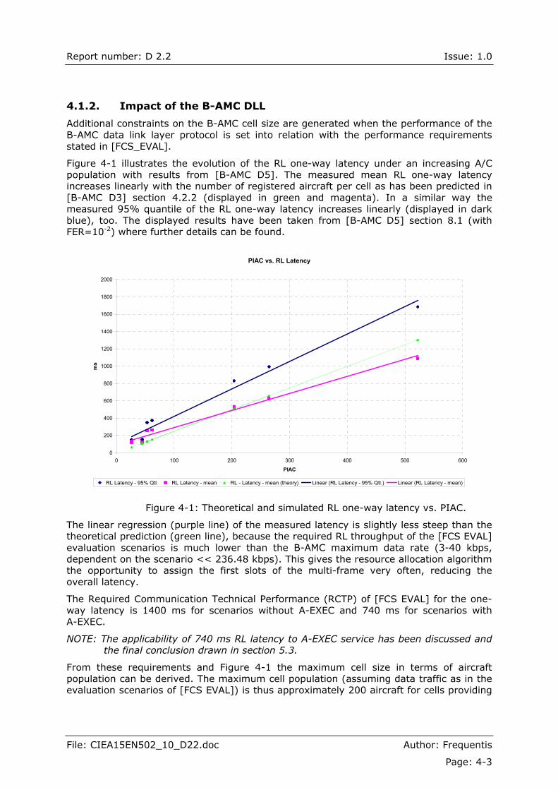
Figure 4-1 illustrates the evolution of the RL one-way latency under an increasing A/C population with results from [B-AMC D5]. The measured mean RL one-way latency increases linearly with the number of registered aircraft per cell as has been predicted in [B-AMC D3] section 4.2.2 (displayed in green and magenta). In a similar way the measured 95% quantile of the RL one-way latency increases linearly (displayed in dark blue), too. The displayed results have been taken from [B-AMC D5] section 8.1 (with FER=10-2) where further details can be found.
PIAC vs. RL Latency
0
200
400
600
800
1000
1200
1400
1600
1800
2000
0 100 200 300 400 500 600
PIAC
ms
RL Latency - 95% Qtl. RL Latency - mean RL - Latency - mean (theory) Linear (RL Latency - 95% Qtl.) Linear (RL Latency - mean)
Figure 4-1: Theoretical and simulated RL one-way latency vs. PIAC.
The linear regression (purple line) of the measured latency is slightly less steep than the theoretical prediction (green line), because the required RL throughput of the [FCS EVAL] evaluation scenarios is much lower than the B-AMC maximum data rate (3-40 kbps, dependent on the scenario << 236.48 kbps). This gives the resource allocation algorithm the opportunity to assign the first slots of the multi-frame very often, reducing the overall latency.
The Required Communication Technical Performance (RCTP) of [FCS EVAL] for the one-way latency is 1400 ms for scenarios without A-EXEC and 740 ms for scenarios with A-EXEC.
NOTE: The applicability of 740 ms RL latency to A-EXEC service has been discussed and the final conclusion drawn in section 5.3.
From these requirements and Figure 4-1 the maximum cell size in terms of aircraft population can be derived. The maximum cell population (assuming data traffic as in the evaluation scenarios of [FCS EVAL]) is thus approximately 200 aircraft for cells providing

Report number: D 2.2 Issue: 1.0
File: CIEA15EN502_10_D22.doc Author: Frequentis
Page: 4-4
A-EXEC service and approximately 400 aircraft if no A-EXEC service is provided. The protocol performance degrades linearly with increase of the number of aircraft. Thus, the B-AMC system in A/G mode provides "graceful performance degradation" as there is no "hard" border where the system would suddenly stop working.
NOTE: [FCS_EVAL] specifies PIAC = 204 for ENR Large service volume and PIAC = 522 aircraft for ENR Super Large service volume.
These numbers do not include the effects of priority handling that have not been simulated in this study. Once the priorities become supported, fine-grained control over the one-way latency will be possible, allowing to significantly increase the number of aircraft per cell.
Here, the conclusion can be drawn that ENR Super Large test volume cannot be supported from single B-AMC GS due to the access constraints on RL.
NOTE: This conclusion has been confirmed later on in section 5.3.
In addition to the maximum aircraft population, the overall available data rate is another limiting factor for the B-AMC cell size. Assuming QPSK modulation and the strongest available coding the maximum data rates are 270.27 kbps on the FL and 236.48 kbps on the RL.
Close examination of the required throughput of the [FCS EVAL] evaluation scenarios indicates that (under above assumptions) a single B-AMC cell probably cannot provide sufficient bandwidth for ENR Large and ENR Super Large test volumes if both AOC and ATS traffic should be supported. However, considering the fact that B-AMC cells are independent of ATC sectors this is hardly a limitation as large areas can be covered by multiple B-AMC cells.
NOTE: Further conclusions about the B-AMC system applicability in different test volumes defined in [FSC_EVAL] can be found in section 5.3.
4.2. B-AMC Service Volume Size (A/A Mode)
As stated in [COCR v2], the maximum aircraft-to-aircraft range is 100 nm. Several options exist for the B-AMC physical layer operating in A/A mode, with cell sizes ranging up to 200 nm. The preferred range is currently 120 nm, which is a little larger than the above mentioned [COCRv2] value.
Based on the physical layer design, the flexible B-AMC A/A protocol has been designed to support the aircraft population within up to 172 nm radius. Thus, the A/A protocol does not impose any additional constraints on the A/A service volume size.
It can be concluded that the currently preferred options for the B-AMC physical layer and protocol design allow for an A/A range of 120 nm, therefore exceeding the [COCRv2] range requirements.
----------- END OF SECTION -----------
Report number: D 2.2 Issue: 1.0
File: CIEA15EN502_10_D22.doc Author: Frequentis
Page: 5-1
5. B-AMC Support for Operational Services
This section describes the categories of communication services, i.e., classes of service (CoS) defined in [COCRv2] that may be used to support the operational services while meeting operational performance requirements.
NOTE: The service classes described in [COCRv2] are not prescriptive (different classifications are possible), but the exemplary classification provided in this reference has been found as useful for B-AMC purposes.
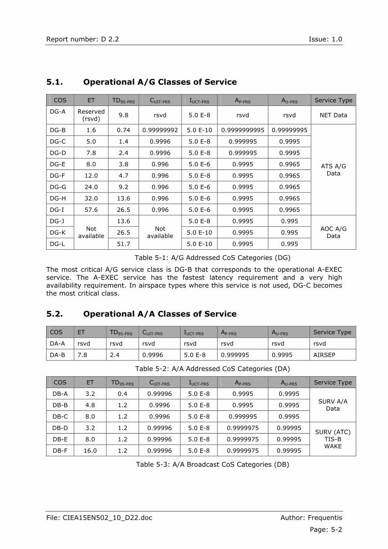
Table 5-1, Table 5-2 and Table 5-3 (copied from [COCRv2]) present the CoS categories for air-ground addressed data, air-air addressed data, and broadcast data, respectively. The meaning of the parameters in these tables is as follows:
! Expiration time (ET) is the time allocated to the one-way transaction after which it can be assumed that the transaction has failed (time after which peer parties should revert to an alternative procedure).
! Technical delay, one way (TD95-FRS) is the time within which 95% of one-way messaging transactions (beginning with user action to send the message, and ending upon notification of recipient of message receipt) are completed.
! Continuity (CUIT) is the probability that a transaction will be completed having meet specified performance (assuming the system was available when the transaction is initiated).
! Integrity (IUCT) is the acceptable rate of transactions that are completed with an undetected error.
! Availability of provision (AP) is the probability that communication with all aircraft in the area is in service (DO-264).
! Availability of use (AU) is the probability that the communication system between the two parties is in service when it is needed
Finally, conclusions are drawn with respect to the applicability of the B-AMC system in providing support of above CoS classes.
Report number: D 2.2 Issue: 1.0
File: CIEA15EN502_10_D22.doc Author: Frequentis
Page: 5-2
5.1. Operational A/G Classes of Service
COS ET TD95-FRS CUIT-FRS IUCT-FRS AP-FRS AU-FRS Service Type
DG-A Reserved (rsvd)
9.8 rsvd 5.0 E-8 rsvd rsvd NET Data
DG-B 1.6 0.74 0.99999992 5.0 E-10 0.9999999995 0.99999995
DG-C 5.0 1.4 0.9996 5.0 E-8 0.999995 0.9995
DG-D 7.8 2.4 0.9996 5.0 E-8 0.999995 0.9995
DG-E 8.0 3.8 0.996 5.0 E-6 0.9995 0.9965
DG-F 12.0 4.7 0.996 5.0 E-8 0.9995 0.9965
DG-G 24.0 9.2 0.996 5.0 E-6 0.9995 0.9965
DG-H 32.0 13.6 0.996 5.0 E-6 0.9995 0.9965
DG-I 57.6 26.5 0.996 5.0 E-6 0.9995 0.9965
ATS A/G Data
DG-J 13.6 5.0 E-8 0.9995 0.995
DG-K 26.5 5.0 E-10 0.9995 0.995
DG-L
Not available
51.7
Not available
5.0 E-10 0.9995 0.995
AOC A/G Data
Table 5-1: A/G Addressed CoS Categories (DG)
The most critical A/G service class is DG-B that corresponds to the operational A-EXEC service. The A-EXEC service has the fastest latency requirement and a very high availability requirement. In airspace types where this service is not used, DG-C becomes the most critical class.
5.2. Operational A/A Classes of Service
COS ET TD95-FRS CUIT-FRS IUCT-FRS AP-FRS AU-FRS Service Type
DA-A rsvd rsvd rsvd rsvd rsvd rsvd rsvd
DA-B 7.8 2.4 0.9996 5.0 E-8 0.999995 0.9995 AIRSEP
Table 5-2: A/A Addressed CoS Categories (DA)
COS ET TD95-FRS CUIT-FRS IUCT-FRS AP-FRS AU-FRS Service Type
DB-A 3.2 0.4 0.99996 5.0 E-8 0.9995 0.9995
DB-B 4.8 1.2 0.9996 5.0 E-8 0.9995 0.9995
DB-C 8.0 1.2 0.9996 5.0 E-8 0.999995 0.9995
SURV A/A Data
DB-D 3.2 1.2 0.99996 5.0 E-8 0.9999975 0.99995
DB-E 8.0 1.2 0.99996 5.0 E-8 0.9999975 0.99995
DB-F 16.0 1.2 0.99996 5.0 E-8 0.9999975 0.99995
SURV (ATC) TIS-B WAKE
Table 5-3: A/A Broadcast CoS Categories (DB)
Report number: D 2.2 Issue: 1.0
File: CIEA15EN502_10_D22.doc Author: Frequentis
Page: 5-3
5.3. A/G Services Supported by B-AMC
This section maps the results of performance simulation of the B-AMC system operating in A/G mode to the appropriate A/G CoS defined in [COCRv2]. The simulation scenarios have been taken from [FCS_EVAL]. Not all [FCS_EVAL] scenarios have been simulated, because some are not applicable to B-AMC. As B-AMC in A/G mode is a duplex system, FL and RL have been separately evaluated.
5.3.1. Inputs for Performance Simulations
The [FCS_EVAL] scenarios define "traffic volumes" (e.g. APT Zone, etc.). Each traffic volume comprises a volume of space, a number of A/C and requires some total throughput for data traffic. The scenarios have been interpreted and the simulations performed as follows:
! The simulation time was set to 1 hour and measurements were recorded after 1600 seconds of simulated time.
! BER values used in capacity/performance simulations have been taken from the interval 10-3 to 5á10-9 as this matches the range of physical layer simulation results very well.
! The total amount of simulated traffic has been generated based on required throughput for the corresponding scenario from [FCS_EVAL]. It is assumed that the maximum number of aircraft in the particular scenario (PIAC) is always within the radio range. The data traffic has been generated as constant size (1000 bit) packets with exponentially distributed inter-arrival times.
! To account for possible additional B-AMC overhead (sub-network overhead, etc., the MAC overhead has already been taken into account) the required throughput has been increased arbitrarily by another 10%.
Due to the fact that the [FCS_EVAL] traffic requirements do not include information on the proportion of the various CoS categories of the total data traffic, the different CoS classes are not distinguished by the simulation. Therefore, the results obtained within this work apply in the same way to all CoS categories.
5.3.2. Results of Performance Simulations
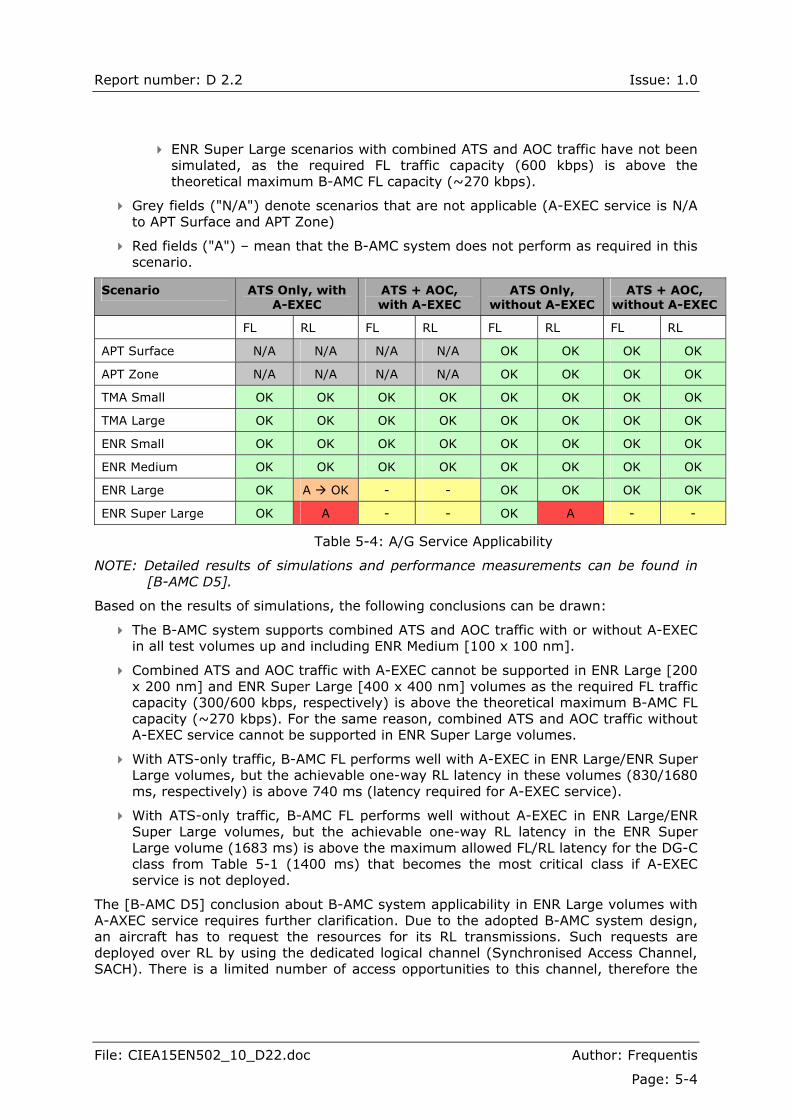
Table 5-4 summarizes the service applicability based on the simulation results obtained in [B-AMC D5] with respect to one-way latency, continuity of service and data integrity. Other CoS attributes were not evaluated by the simulations (e.g. availability of provision, availability of use, etc.). The presented results apply for a BER below 5á10-6 (equivalent to a FER below 10-2) as this has been identified to be the upper bound for acceptable protocol performance.
! Green fields ("OK") mean that all service types can be supported in this scenario.
! Yellow fields ("-") denote scenarios that were not simulated, because the required throughput is beyond the theoretical maximum data rate that can be provided by the B-AMC system.
! ENR Large scenario with combined ATS and AOC traffic including A-EXEC service has not been simulated, as the required FL traffic capacity (300 kbps) is above the theoretical maximum B-AMC FL capacity (~270 kbps).
Report number: D 2.2 Issue: 1.0
File: CIEA15EN502_10_D22.doc Author: Frequentis
Page: 5-4
! ENR Super Large scenarios with combined ATS and AOC traffic have not been simulated, as the required FL traffic capacity (600 kbps) is above the theoretical maximum B-AMC FL capacity (~270 kbps).
! Grey fields ("N/A") denote scenarios that are not applicable (A-EXEC service is N/A to APT Surface and APT Zone)
! Red fields ("A") � mean that the B-AMC system does not perform as required in this scenario.
Scenario ATS Only, with A-EXEC
ATS + AOC, with A-EXEC
ATS Only, without A-EXEC
ATS + AOC, without A-EXEC
FL RL FL RL FL RL FL RL
APT Surface N/A N/A N/A N/A OK OK OK OK
APT Zone N/A N/A N/A N/A OK OK OK OK
TMA Small OK OK OK OK OK OK OK OK
TMA Large OK OK OK OK OK OK OK OK
ENR Small OK OK OK OK OK OK OK OK
ENR Medium OK OK OK OK OK OK OK OK
ENR Large OK A ! OK - - OK OK OK OK
ENR Super Large OK A - - OK A - -
Table 5-4: A/G Service Applicability
NOTE: Detailed results of simulations and performance measurements can be found in [B-AMC D5].
Based on the results of simulations, the following conclusions can be drawn:
! The B-AMC system supports combined ATS and AOC traffic with or without A-EXEC in all test volumes up and including ENR Medium [100 x 100 nm].
! Combined ATS and AOC traffic with A-EXEC cannot be supported in ENR Large [200 x 200 nm] and ENR Super Large [400 x 400 nm] volumes as the required FL traffic capacity (300/600 kbps, respectively) is above the theoretical maximum B-AMC FL capacity (~270 kbps). For the same reason, combined ATS and AOC traffic without A-EXEC service cannot be supported in ENR Super Large volumes.
! With ATS-only traffic, B-AMC FL performs well with A-EXEC in ENR Large/ENR Super Large volumes, but the achievable one-way RL latency in these volumes (830/1680 ms, respectively) is above 740 ms (latency required for A-EXEC service).
! With ATS-only traffic, B-AMC FL performs well without A-EXEC in ENR Large/ENR Super Large volumes, but the achievable one-way RL latency in the ENR Super Large volume (1683 ms) is above the maximum allowed FL/RL latency for the DG-C class from Table 5-1 (1400 ms) that becomes the most critical class if A-EXEC service is not deployed.
The [B-AMC D5] conclusion about B-AMC system applicability in ENR Large volumes with A-AXEC service requires further clarification. Due to the adopted B-AMC system design, an aircraft has to request the resources for its RL transmissions. Such requests are deployed over RL by using the dedicated logical channel (Synchronised Access Channel, SACH). There is a limited number of access opportunities to this channel, therefore the
Report number: D 2.2 Issue: 1.0
File: CIEA15EN502_10_D22.doc Author: Frequentis
Page: 5-5
RL access delay and the RL overall transmission latency are significantly longer than the corresponding FL values.
System evaluations performed in [B-AMC D5] assumed that the A-EXEC latency requirement (740 ms) applies to both FL and RL scenarios. However, the more detailed description of the A-EXEC service provided in [COCRv2] indicates that the entire A-EXEC transaction includes single FL message containing the clearance instruction. Therefore, the latency requirement (740 ms) would apply only to the FL.
The detailed results from [B-AMC D5] (Table 8-23, Table 8-24, Table 8-25 and Table 8-26) show that in ENR Large and ENR Super Large scenarios with ATS-only traffic the FL latency (at most 56 ms) is well below the value of 740 ms. Moreover, the FL A-EXEC message would be confirmed on RL within at most 650 ms.
Therefore, it may be concluded that with A-EXEC deployed on FL only, the B-AMC system would be well able to support ATS-only scenarios with and without the A-EXEC service in ENR Large volumes ("A" entry in the second last row in Table 5-4 would become "OK").
5.3.3. Impact of the RL Bandwidth
During the protocol performance simulation in [B-AMC D5], the RL bandwidth was set to 500 kHz, providing maximum RL capacity of 236 kbps. This capacity by far exceeds the RL capacity (scenario-dependent, at most ~50 kbps) required in [FSC-EVAL].
However, RL physical layer investigations in [B-AMC D5] have led to the conclusion that the RL bandwidth should be reduced to 250 kHz in order to reduce interference impact coming from airborne DME interrogators.
The consequence is that the T48 transport channel (that includes all 48 OFDM carriers and was actually used for protocol simulations) would no longer be available on RL. This is not a severe problem, as the typical packet size (see [B-AMC D5]) requires a T24 allocation (channel with 24 OFDM carriers). The RL throughput would be reduced, but would still lie far above what is required.
Another implication of the RL bandwidth reduction is that the number of RL dedicated control channels would drop from 48 to 24 per multi-frame. In order to keep the 48 RL access opportunities per multi-frame and preserve current protocol performance (latency), a second SACH and DCCH slot pair would have to be introduced into the RL multi-frame format.
NOTE: SACH denotes Synchronised Access Channel, DCCH denotes Dedicated Control Channel.
The available RL capacity would drop to ~84 kbps, however, this is not seen as a severe problem as the maximum required RL capacity needed [FCS_EVAL] is at most 50 kbps in the scenarios applicable to B-AMC.
5.4. A/A and Broadcast Services Supported by B-AMC
This section maps the results of performance simulation of the B-AMC system operating in A/A mode to the appropriate A/A and broadcast CoS defined in [COCRv2].
Report number: D 2.2 Issue: 1.0
File: CIEA15EN502_10_D22.doc Author: Frequentis
Page: 5-6
5.4.1. Inputs for Performance Simulations
The simulation scenarios are aligned with these proposed in [FCS_EVAL]. These results were obtained for the purpose of this report under following assumptions:
! SURV scenario for ENR case from [FCS_EVAL] Table 4-3 has been chosen for B-AMC A/A simulations.
! This scenario was slightly modified by reducing the range from original 200 nm (defined in the previous version of [FCS_EVAL]) to 172 nm (maximum range supported by the B-AMC A/A protocol design). This leads to a reduced aircraft population of 813 aircraft.
! Further simplifications were made. The effective number of transmitting aircraft was reduced to PIAC/5 and the message update rate was correspondingly changed from one message every 5 seconds to one message every second to preserve the same effective message update rate.
! A/A data packets were generated with an exponential distribution with a mean inter-arrival time of 1 second.
! A simple topology has been used which assumes all aircraft to be at the same flight level. Aircraft participating in a scenario are initially uniformly distributed and then they randomly move within the simulation area (defined as a square of 450x450 nm). The simulations consider transmissions of all aircraft (1722) within the simulation area. However, observations were only made in the circular area with radius 172 nm in the centre of the simulation area.
! Simulation time was set to 380 seconds, but measurements were only made in the last 150 seconds of the simulation.
! Several simulations with different initial positions of the aircraft within the simulation area have been carried out.
! A/A simulations are based on the bit error rate provided by the physical layer (BER = 10-4).
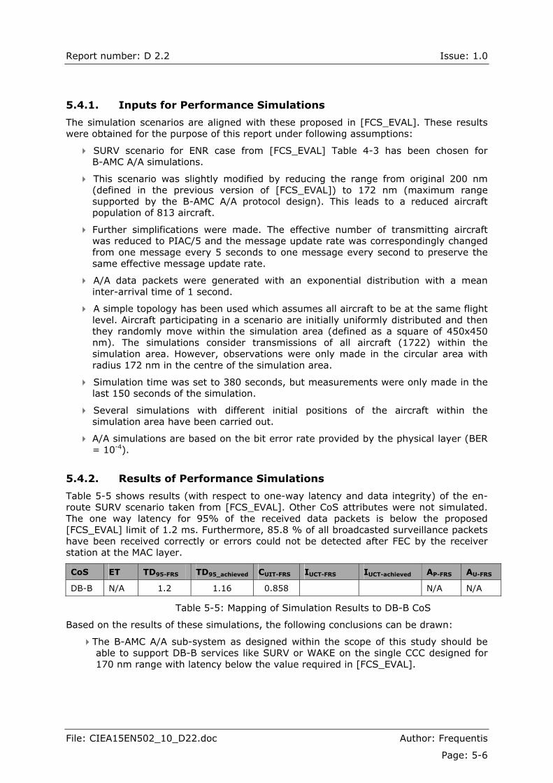
5.4.2. Results of Performance Simulations
Table 5-5 shows results (with respect to one-way latency and data integrity) of the en-route SURV scenario taken from [FCS_EVAL]. Other CoS attributes were not simulated. The one way latency for 95% of the received data packets is below the proposed [FCS_EVAL] limit of 1.2 ms. Furthermore, 85.8 % of all broadcasted surveillance packets have been received correctly or errors could not be detected after FEC by the receiver station at the MAC layer.
CoS ET TD95-FRS TD95_achieved CUIT-FRS IUCT-FRS IUCT-achieved AP-FRS AU-FRS
DB-B N/A 1.2 1.16 0.858 N/A N/A
Table 5-5: Mapping of Simulation Results to DB-B CoS
Based on the results of these simulations, the following conclusions can be drawn:
! The B-AMC A/A sub-system as designed within the scope of this study should be able to support DB-B services like SURV or WAKE on the single CCC designed for 170 nm range with latency below the value required in [FCS_EVAL].

Report number: D 2.2 Issue: 1.0
File: CIEA15EN502_10_D22.doc Author: Frequentis
Page: 5-7
! This conclusion does not take all [FCS_EVAL] requirements into account. In order to make a firm statement, further investigations and simulations are proposed to be done in future work.
----------- END OF SECTION -----------

Report number: D 2.2 Issue: 1.0
File: CIEA15EN502_10_D22.doc Author: Frequentis
Page: 6-1
6. B-AMC Deployment Scenarios
6.1. L-band Usage by the B-AMC System
The proposed L-band usage for the B-AMC A/G and A/A sub-systems is shown in Figure 6-1.
Figure 6-1: Proposed L-band Usage for B-AMC A/G and A/A Communications
6.1.1. Channel Scheme for the B-AMC A/G Sub-system
The approach for allocating FL and RL channels for B-AMC A/G operation follows the OPTN2 discussed in [B-AMC D1]. The preliminary results of interference simulations have shown that OPTN1 where B-AMC channels would be placed at 500 kHz offset from existing DME channel allocations without applying mutual frequency planning rules will not provide sufficient isolation between systems both due to limited selectivity of the involved receivers and relatively broad spectrum of the transmitted signals.
Therefore, the preferred deployment concept for the B-AMC A/G sub-system is OPTN2. When allocating B-AMC FL/RL channels, the existing DME frequency planning criteria (that currently comprise co-channel, adjacent channel and second adjacent channel cases) would be respected and supplemented by specific rules for minimum separation to the B-AMC system in both spatial and frequency domain. With OPTN2, the B-AMC channels are still placed at 500 kHz offset from DME channels, but local DME allocations are avoided, based on such supplementary rules.
NOTE: Detailed frequency planning is a complicated issue and could not be addressed within this study. Should the development of supplementary rules for B-AMC deployment along with DME channels prove to be not feasible, the system could be deployed by following OPTN3 where a minimum number of required B-AMC FL/RL channel pairs would be made exclusively available for B-AMC A/G operations (DME operations on/around these channels would be shut-down).
Report number: D 2.2 Issue: 1.0
File: CIEA15EN502_10_D22.doc Author: Frequentis
Page: 6-2
An inspection of the DME channel plan and actual channel assignments in Europe (Figures 9, 10 and 11 in [B-AMC D1]) allows for the following conclusions:
! There are significantly more X-channel assignments in the lower L-band range (1-63X) than in the upper range (64-126X). The lowest assignment density is observed for (64-126Y) channels. This is probably due to the larger sizes of the volumes served by (64-126X) respectively (64-126Y) channels.
! The B-AMC GS TX could, under constraints of mutual frequency planning criteria, transmit on channels (985-1009 MHz) that lie within the sub-band normally used by the ground DME TX for FL transmissions on (1-63X) channels. Within this range, only FL operation would apply to both systems.
! The B-AMC GS RX could, under constraints of mutual frequency planning criteria, operate on channels (1048-1072 MHz) that lie within the sub-band used by the ground DME RX for reception on (1-63X) and (1-63Y) channels. However, the same range can be used by the ground DME TX for transmissions on (64-126Y) channels.
! With an alternative approach, the B-AMC GS RX could, again under constraints of mutual frequency planning criteria, operate on channels (1111-1135 MHz) that lie within the sub-band used by the ground DME RX for reception on (64-126X) and (64-126Y) channels. However, the same range can be used by the ground DME TX for transmissions on (1-63Y) channels.
The proposed deployment option is to consider a sub-band containing an appropriate number of B-AMC FL channels within the lowest part of the L-band (962-1024 MHz) while the sub-band with B-AMC RL channels is created in the middle of the 1025-1087 MHz range. Assuming the maximum pool of 24 B-AMC FL/RL channels (see section 6.3), the FL B-AMC sub-band may comprise the 985-1009 MHz range, while the RL channels may be deployed in the 1048-1072 MHz range. With such an allocation, the B-AMC duplex spacing would be the same as for DME system.
NOTE: This allocation is preliminary, guided by the findings of the interference investigations within this study � it may have to be reviewed after the supplementary detailed interference investigations/measurements in the future work. The B-AMC physical layer design generally allows for flexible selection of FL and RL channels (therefore for flexible duplex spacing) as long as (because of diplexer constraints) these channels remain within their defined sub-band. Flexible duplex spacing other than 63 MHz would allow for more flexibility when searching for optimum FL and RL channel allocations, however with more impact upon DME frequency planning. In such a case, a continuous block of 24 RL channels could be optionally allocated e.g. in the 1111-1135 MHz range (as shown in Figure 6-1).
Not all 24 channels from the sub-bands mentioned above would be effectively required for B-AMC A/G operations (see section 6.3). It is just proposed to select the required FL/RL channels from such contiguous sub-bands. This could offer more freedom for frequency planning while providing a degree of frequency isolation from the fixed L-band allocations.
NOTE: An apparent advantage of such an allocation is that any B-AMC RL channel would be operated at a guaranteed minimum distance of 18 MHz to the fixed SSR allocations (1030 and 1090 MHz). At the same time, B-AMC FL channels would be operated at 21 MHz distance to the FL SSR/ACAS channel (1030 MHz) and at 7 MHz distance from the fixed UAT allocation (978 MHz). This may enable the
Report number: D 2.2 Issue: 1.0
File: CIEA15EN502_10_D22.doc Author: Frequentis
Page: 6-3
usage of RF filters within the B-AMC TX/RX, operating over the B-AMC FL/RL sub-bands, therefore relaxing the B-AMC co-siting efforts [B-AMC D4].
6.1.2. Channel Scheme for the B-AMC A/A Sub-system
The approach for allocating CCCs for the B-AMC A/A operation follows the OPTN3 discussed in [B-AMC D1]. With that option, parts of the L-band spectrum would be dedicated to B-AMC operations (no other systems would operate within and around such dedicated spectrum blocks).
The proposed frequency allocation for the globally available CCC for B-AMC A/A communication is also shown in Figure 6-1. The CCC centre frequency is proposed to be placed at 968 MHz. Such an allocation would relax the co-existence between the B-AMC radio operating in A/A mode and the close UAT radios, while providing some guard frequency distance towards the UMTS/GSM systems operating at frequencies immediately below the aeronautical L-band. The estimated RF bandwidth of the CCC is 2.6 MHz.
If required, separate CCC-TMA and CCC-APT channels, each with 1.3 MHz bandwidth could be located above/below the CCC-ENR at the required frequency distance to enable interference-free simultaneous usage.
NOTE: The interference investigations of the B-AMC A/A mode could not be performed within this study.
6.2. B-AMC TX Power and RX Protected Signal Level
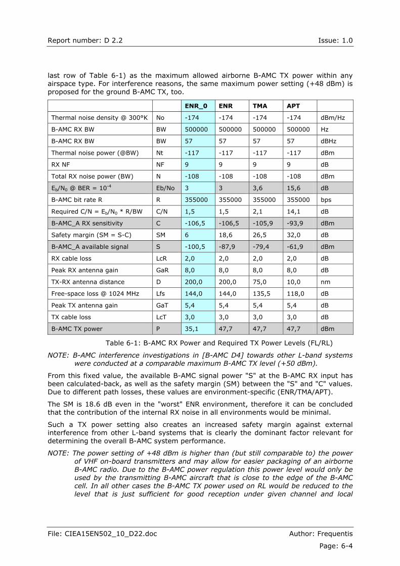
Table 6-1 shows the exemplary FL/RL link budget calculation for the B-AMC A/G system operating under noise-only conditions (no external interference) and with full bandwidth (500 kHz) in different environments (ENR/TMA/APT). The (shaded) values for required Eb/No ratio for achieving the minimum BER of 10-4 have been adopted from [B-AMC D4]. It has been assumed that an airborne TX uses all OFDM carriers (full RL bandwidth).
These values include a real channel model (Rayleigh/Rice, respectively) applicable to the particular airspace and the corresponding channel coding. As the receiver noise is the same in both cases, the Eb/No ratio increases in the APT environment compared to the Eb/No in ENR and TMA environment. This is due to the different nature of the APT communication channel (Rayleigh instead of Rice).
Taking the B-AMC RX noise bandwidth (500 kHz) and the effective achievable bit rate (355 kbps) into account, the corresponding C/N ratio has been calculated, leading to the B-AMC RX sensitivity values C. By applying a fixed safety margin of 6 dB, the B-AMC RX "protected signal levels" S could be calculated for each airspace type. Finally, taking maximum airborne and ground antenna gains, TX and RX cable losses as well as free-space loss (calculated at 1024 MHz) into account, the required minimum TX power (measured at the TX terminals) of the ground B-AMC transmitter could be obtained. In the ENR case, the required TX power would become +35.1 dBm. Without interference, the same power setting would apply to the airborne B-AMC TX.
However, due to the expected L-band interference from e.g. airborne and ground DME transmitters, the ground B-AMC receiver may not be able to operate properly with such transmitter power setting. On the other side, the maximum airborne B-AMC transmitter power should be limited in order not to disturb other L-band receivers. It is therefore proposed to consider the fixed TX power value (+47.7 dBm, rounded-up to +48 dBm,
Report number: D 2.2 Issue: 1.0
File: CIEA15EN502_10_D22.doc Author: Frequentis
Page: 6-4
last row of Table 6-1) as the maximum allowed airborne B-AMC TX power within any airspace type. For interference reasons, the same maximum power setting (+48 dBm) is proposed for the ground B-AMC TX, too.
ENR_0 ENR TMA APT
Thermal noise density @ 300°K No -174 -174 -174 -174 dBm/Hz
B-AMC RX BW BW 500000 500000 500000 500000 Hz
B-AMC RX BW BW 57 57 57 57 dBHz
Thermal noise power (@BW) Nt -117 -117 -117 -117 dBm
RX NF NF 9 9 9 9 dB
Total RX noise power (BW) N -108 -108 -108 -108 dBm
Eb/N0 @ BER = 10-4 Eb/No 3 3 3,6 15,6 dB
B-AMC bit rate R R 355000 355000 355000 355000 bps
Required C/N = Eb/N0 * R/BW C/N 1,5 1,5 2,1 14,1 dB
B-AMC_A RX sensitivity C -106,5 -106,5 -105,9 -93,9 dBm
Safety margin (SM = S-C) SM 6 18,6 26,5 32,0 dB
B-AMC_A available signal S -100,5 -87,9 -79,4 -61,9 dBm
RX cable loss LcR 2,0 2,0 2,0 2,0 dB
Peak RX antenna gain GaR 8,0 8,0 8,0 8,0 dB
TX-RX antenna distance D 200,0 200,0 75,0 10,0 nm
Free-space loss @ 1024 MHz Lfs 144,0 144,0 135,5 118,0 dB
Peak TX antenna gain GaT 5,4 5,4 5,4 5,4 dB
TX cable loss LcT 3,0 3,0 3,0 3,0 dB
B-AMC TX power P 35,1 47,7 47,7 47,7 dBm
Table 6-1: B-AMC RX Power and Required TX Power Levels (FL/RL)
NOTE: B-AMC interference investigations in [B-AMC D4] towards other L-band systems were conducted at a comparable maximum B-AMC TX level (+50 dBm).
From this fixed value, the available B-AMC signal power "S" at the B-AMC RX input has been calculated-back, as well as the safety margin (SM) between the "S" and "C" values. Due to different path losses, these values are environment-specific (ENR/TMA/APT).
The SM is 18.6 dB even in the "worst" ENR environment, therefore it can be concluded that the contribution of the internal RX noise in all environments would be minimal.
Such a TX power setting also creates an increased safety margin against external interference from other L-band systems that is clearly the dominant factor relevant for determining the overall B-AMC system performance.
NOTE: The power setting of +48 dBm is higher than (but still comparable to) the power of VHF on-board transmitters and may allow for easier packaging of an airborne B-AMC radio. Due to the B-AMC power regulation this power level would only be used by the transmitting B-AMC aircraft that is close to the edge of the B-AMC cell. In all other cases the B-AMC TX power used on RL would be reduced to the level that is just sufficient for good reception under given channel and local
Report number: D 2.2 Issue: 1.0
File: CIEA15EN502_10_D22.doc Author: Frequentis
Page: 6-5
interference conditions. This would further reduce the impact of interference caused by the airborne B-AMC transmitter upon other L-band systems.
6.3. Cellular Planning Principles for B-AMC
For the purposes of this study, simple principles have been developed for B-AMC cellular planning. It has been assumed that the interfering co-channel B-AMC signal is received via the same antenna from the same direction (with the same antenna gain) as the desired B-AMC signal. Furthermore, it has been assumed that both the desired and the undesired B-AMC transmitter operate at the same power level, using identical cabling and antenna patterns (both produce the same EIRP).
In order to achieve the aggregate ENR coverage, first a number of B-AMC cells with the same TX power and the same coverage radius are combined into a cluster of cells.
Then, a required number of such clusters are virtually deployed, by respecting the re-use distance for each cell that in turn depends on the required C/I ratio for the undisturbed B-AMC operation. All clusters are of the same size and each cluster uses the same set of B-AMC channels. The number of B-AMC channels within a cluster is equal to the maximum number of channels for regional B-AMC coverage.
NOTE: TMA B-AMC systems may have different operational coverage and capacity requirements and their GSs may not always be deployable at locations used for ENR purposes. APT systems must be located directly at the airport. Therefore, additional number of B-AMC RF channels will be required for APTs and some TMA service volumes.
6.3.1. Required S/I vs. Cluster Size
Assuming the radius "R" of a hexagonal cell and the number of cells pro cluster "Nc", the re-use distance "D" between the co-channel B-AMC GSs is given by [CELLULAR]
RNcD **3=
and the re-use factor "Q" by
NcRDQ *3/ == .
For a simple topology with equal TX power in each cell, the victim RX of an aircraft is assumed to be at the boundary of the controlling cell at an approximate distance "D" from the first tier of 6 co-channel B-AMC base stations. All GSs are within the line-of-sight of the aircraft RX. The contributions of further co-channel GSs beyond the closest 6 GSs have been neglected.
NOTE: The opposite case applies to B-AMC RL where (multiple) aircraft controlled by other co-channel GSs and flying at the boundary of their service volumes jam the RL transmissions of the aircraft being controlled by and flying at the boundary of the "middle" GS. However, the probability that an A/C transmits on RL is much lower than the probability of GS FL transmissions (100%) and the probability that such transmissions would simultaneously occur is even lower. Additionally considering that an aircraft gets in the normal case not all RL carriers assigned and therefore it will not transmit at full power, this scenario was deemed to be not constraining and was not investigated in detail.

Report number: D 2.2 Issue: 1.0
File: CIEA15EN502_10_D22.doc Author: Frequentis
Page: 6-6
In such a case the ratio of the desired signal "S" from the controlling GS to the total co-channel interference produced by 6 surrounding GSs is given by the simplified equation
( )2
*3*61*
61*
61/
22 NcNc
RDQIS ==⎟⎠⎞
⎜⎝⎛== .
Table 6-2 shows approximatly the signal-to-interference ratio S/I versus the cluster size Nc, assuming simultaneous contributions of the 6 closest interfering co-channel B-AMC GSs.
Cluster Size Nc 3 4 7 9 12 13
S/I (dB), 6 co-channel cells 1,8 3 5,4 6,5 7,8 8,8
Table 6-2: Available S/I vs. Cluster Size Nc
From this table, the appropriate cluster size "Nc" should be selected for the B-AMC A/G sub-system, based on the observed system co-channel performance.
6.3.2. B-AMC Co-channel Protection Ratio
[EUR_FMM] provides information about frequency planning principles and procedures when deploying different kinds of aeronautical radio systems. Frequency planning is performed by applying rules previously established for pairs of involved transmitters and receivers. These rules define the necessary isolation (spacing, frequency) between the involved transmitters and receivers. If different systems participate in the interference scenario, the method is applied in both directions (the RX of each of the involved systems is supposed to become an interference victim, and the worst case is retained).
The co-channel (co-frequency) protection ratio (D/U) that is used in [EUR_FMM], e.g. for DME frequency planning, is defined for one TX/RX pair without taking possible multiple interference contributions from multiple sources into account.
In order to propose the basic rules for the B-AMC frequency planning, the following observations can be made:
! Each co-channel B-AMC GS produces an OFDM signal with flat in-band spectrum.
! For an airborne B-AMC receiver that is synchronised to its controlling B-AMC GS, the uncorrelated co-channel interference signal received from another B-AMC GS is "noise-like".
! Considering multiple B-AMC GSs within the reception range of the victim B-AMC RX, the composite interference signal received from up to 6 co-channel B-AMC GSs would be even more "noise-like".
Therefore, the co-channel interference impact from neighbouring B-AMC cells has been estimated in such a way that it has the same impact as an increase of the internal RX noise level.
In Table 6-1, without any interference, the required C/N ratio (dB) has been defined as
5,1=⎟⎠⎞
⎜⎝⎛
NC
assuming an ENR channel type (Rice). The corresponding minimum received signal power C would be -106.5 dBm in that case.
Report number: D 2.2 Issue: 1.0
File: CIEA15EN502_10_D22.doc Author: Frequentis
Page: 6-7
Due to the expected interference from other L-band systems, an airborne B-AMC victim RX operates in all environments at desired signal levels S (-88 dBm � -62 dBm, see Table 6-1) far above the minimum signal level C (-106.5 dBm) that would be required solely due to the combined (RX noise + communications channel) impact. Therefore, the following relation applies:
( ) IcS
IcNS
≈+
,
where S is the actual received power from the desired B-AMC TX and Ic is the co-channel interference power received from a different B-AMC system.
As the APT/TMA channel impact is already covered by the increased margin, the above relation also applies to these environments.
Assuming that the impact of Ic is the same as an increased RX power, the B-AMC receiver would be able to perform well (i.e. provide the required BER) if the above ratio due to the "noisy" co-channel interference again becomes equal to the minimum C/N ratio without any interference:
5,1==NC
IcS
(dB)
For B-AMC planning purposes it is proposed to consider that the co-channel interference is, like for other cellular systems, produced not only by a single co-channel cell, but simultaneously by six adjacent cells, where each of the six surrounding GS equally contributes to the interference power. Such simultaneous contribution of six cells has already been considered in the second row in Table 6-2.
According to Table 6-2, the acceptable S/Ic = C/N value of 1.5 dB would allow for the cluster size of Nc = 3, with the corresponding re-use distance equal to 2.9. Taking into account that in the worst-case scenario not all interfering cells are at the same distance from the victim RX and considering an additional implementation margin, it is proposed to take Nc = 7 as appropriate for B-AMC cellular planning, leading to the re-use distance of 4.56. The resulting cellular re-use pattern with the cell radius "R" and the re-use distance of 4.6áR is shown in Figure 6-2.

Report number: D 2.2 Issue: 1.0
File: CIEA15EN502_10_D22.doc Author: Frequentis
Page: 6-8
Figure 6-2: B-AMC Cellular Re-use Pattern
6.4. Data-only vs. Voice-data B-AMC System Deployment
As it was relatively easy to accommodate digital voice within the modified L-band framing, the B-AMC system has been designed [B-AMC D2.1] as an integrated voice-data system. This allows for configuring a limited number of voice channels when and where required (excessive usage of voice communications in the L-band is not anticipated).
Investigations of airborne co-location issues in [B-AMC D4] have shown that the FL reception of an airborne B-AMC RX would probably be heavily jammed each time an airborne L-band system (DME, SSR, UAT) starts to transmit. The same assumption has also been made for an airborne UAT receiver in [UAT_M] and would probably apply to any other on-board L-band receiver.
Furthermore, in [B-AMC D4] it has been concluded that in order not to disturb other on-board L-band receivers, the duty-cycle of an airborne B-AMC TX should be kept as low as possible. The maximum duty-cycle for a data-only B-AMC system was estimated as 11% during about 60 ms, with the typical long-term average value far below this value (0.65%). The operational impact of such a duty-cycle upon other systems requires further investigations, but preliminary it may be regarded as acceptable.
However, adding voice channels would mean that the airborne duty-cycle would be increased by additional 11% during about 3 seconds (typical duration of an ATC voice session that would apply to the pilot�s RL voice transmission). Such an increased duty-cycle of 22% may not be operationally acceptable any more from another systems� point of view.
Finally, allocating voice channels means reducing the effective B-AMC bandwidth available for data link services that are of major concern in the L-band.
Therefore, the scenarios with voice channels deployed over the B-AMC A/G system in the L-band may locally apply, but were not investigated in this deliverable. All proposed A/G deployment scenarios assume that the B-AMC system provides only data link services.
4,6áR
R

Report number: D 2.2 Issue: 1.0
File: CIEA15EN502_10_D22.doc Author: Frequentis
Page: 6-9
6.5. B-AMC Areas of Applicability
Summarizing the findings in previous sections of this report (coverage constraints, performance issues), the following general conclusions and recommendations about the B-AMC system applicability to aeronautical services and applications can be made:
! Assuming the deployment option with frequency planning (OPTN2), the B-AMC A/G sub-system operating under specified DME interference scenarios can support cell sizes with radius up to 200 nm.
! The B-AMC A/G system performs generally poor when DME and JTIDS interference as specified in [B-AMC D5] is present simultaneously. As such behaviour was not observed for existing L-band systems (that are also exposed to JTIDS interference), the impact of JTIDS interference onto B-AMC system should be further investigated.
NOTE: [FSCA-L] just describes different L-band systems and recommends that the aggregate interference from existing systems should be modelled and simulated, but does not provide detailed scenarios for interference investigations. The provisory scenarios created and used in B-AMC interference investigations may have been too pessimistic.
! The B-AMC system (single GS) supports combined ATS and AOC traffic with or without A-EXEC in all service volumes up to 50 nm range. This makes the B-AMC A/G sub-system well applicable to the APT (APT Surface, APT Zone) and TMA domains.
! The B-AMC A/G sub-system (single GS) supports AOC traffic and ATS traffic without A-EXEC service up to ~ 100 nm range. Single B-AMC GS also supports ATS only traffic with A-EXEC service installed up to ~ 100 nm range. Therefore, the system is also well suitable for providing ENR services.
! ENR services, which for coverage reasons cannot be provided from one single B-AMC GS, can be easily accommodated if a required number of GSs with smaller coverage (e.g. 100 nm) is deployed, with seamless handover between the involved GSs.
! The B-AMC A/A sub-system designed within the scope of this study and deployed by using OPTN3 should be able to support DB-B services like SURV or WAKE on the single CCC designed for 170 nm range with latency below the value required in [FCS_EVAL].
Above conclusions have been derived within this study under stringent conditions, considering the highest possible aircraft density and the most demanding A/G services [FCS_EVAL]. It is expected that in practice such conditions may well apply to the European areas with densest air traffic (e.g. airspace around London, Paris, Frankfurt, Amsterdam and Brussels).
In many practical cases, local circumstances may be less demanding. Therefore, it may still be possible to deploy some ATS B-AMC GSs with coverage of up to 200 nm. In many cases, it may also be possible to provide combined ATS and AOC services with 200 nm coverage to reduced aircraft population in less densely populated airspaces.
Moreover, the results of B-AMC performance simulations have been derived without taking into account benefits of prioritisation between different A/G classes of service. Although [COCRv2] contains required detailed data, the generation/simulation of detailed traffic patterns based on the realistic mix of operational services was not feasible because of the very short time frame for the B-AMC study.
Report number: D 2.2 Issue: 1.0
File: CIEA15EN502_10_D22.doc Author: Frequentis
Page: 6-10
Based on the B-AMC results and lessons learned within the B-AMC study, two recommendations can be made with respect to future FCS activities:
RECOMMENDATION 1: Detailed commonly agreed interference scenarios based on the common inputs should be prepared and used in the next phases of the FCS investigations in order to enable a fair comparison of candidate L-band technologies.
RECOMMENDATION 2: Detailed commonly agreed data traffic scenarios based on [COCRv2] inputs should be prepared for different flight phases in different domains (APT Surface, APT Zone, TMA, ENR, ORP, AOA). Such detailed scenarios should be used as a common input in the next phases of FCS activities and would allow for detailed investigations and fair comparison of internal priority management mechanisms and performance of candidate FRS technologies.
6.6. A/G Deployment � ENR Coverage
This scenario is related to the deployment of the B-AMC A/G sub-system for the provision of an A/G data link with ENR coverage (with vertical boundaries, according to [FCS_EVAL], between FL 245 and FL 450).
6.6.1. Scenario Description
The preferred B-AMC A/G sub-system deployment option is B-AMC as data-only system. The proposed approach requires neither a dedicated B-AMC airspace segregated from other airspace types, nor mandatory carriage of B-AMC radios (however, it does not preclude implementation rules based on mandatory carriage of B-AMC equipment). Equipped users would receive B-AMC services with associated benefits via the B-AMC airborne radio operating in A/G mode. Other users would be able to continue to use the narrowband data link equipment (e.g. VDL Mode 2) as long as it remains supported in the ENR airspace.
With that scenario, interference caused by an airborne B-AMC TX towards close ground DME/TACAN stations and other L-band ground systems is expected [B-AMC D4] to be generally not severe, due to the relatively large spatial separation (minimum 7 km at FL 245). Assuming proper frequency planning (2.5 MHz frequency spacing between systems), DME systems on other A/C interrogating "local" DME GSs would not be jammed by the airborne B-AMC TX. The interference towards UAT receivers of close aircraft or UAT ground stations requires further investigation ([B-AMC D4] assumptions and results obtained for that case may be too pessimistic).
With the data-only deployment concept, the ground B-AMC system architecture [B-AMC D6] becomes simplified, as all voice-relevant functions and components may be omitted. Voice service within the B-AMC deployment area would be completely decoupled from the B-AMC system, provided as an "external" DSB-AM service within the VHF COM range. The B-AMC GNI is still required, but would only need to interface via ATN routers with external data link systems.
NOTE: Within the context of the B-AMC study, ATN means either ATN/OSI or ATN/IP. In the future, dependent on the acceptance of an end-to-end IP concept, ATN IP A/G routers may replace current ATN OSI A/G routers.

Report number: D 2.2 Issue: 1.0
File: CIEA15EN502_10_D22.doc Author: Frequentis
Page: 6-11
All involved ATS/AOC ground systems would have to configure/provide an ATN-compatible data link service. Optionally, a gateway may be used between non-ATN AOC systems and the ATN-compatible part of the ground infrastructure.
All cells (GSCs) are attached to the B-AMC GNI that in turn is connected to an external ATN A/G router. The ground data link network architecture would remain similar to the IP-based architecture that is used today by the Service Providers (SPs, SITA and ARINC) when providing ATN/OSI data link services over VDL Mode 2.
As data link coverage is even today completely de-coupled from the voice coverage, similar service provision arrangements between the communications Service Providers (mainly ARINC and SITA) and Air Navigation Service Providers (ANSPs) are possible as today. Moreover, due to the relatively large frequency separation between the VHF- and the L-band, it may be possible to deploy B-AMC ground radio equipment co-located with the current VDL Mode 2 radios.
NOTE: The B-AMC system could be seen by SPs as the follow-on technology for the currently used VDL Mode 2.
Sub-scenario #1
Taking the conclusions from section 6.5 into account, combined ATS and AOC services (without A-EXEC service) could be provided by using B-AMC cells with up to 100 nm coverage. Due to the shorter antenna size in the L-band compared to the VHF range, beam-forming techniques may be used as a means to increase the required operational coverage, e.g. for off-shore operations.
Sub-scenario #2
Assuming proper site engineering, ANSPs may also decide to deploy B-AMC GSs at existing VHF voice radio sites. Again, coverage of up to 100 nm would be possible from each GS, assuming that A-EXEC service is excluded. The results of the B-AMC RL simulations [B-AMC D5] show that there is a potential to achieve even 200 nm range with this scenario (achieved RL latency of 1680 ms is just slightly above the required value of 1400 ms).
6.6.2. Required RF Bandwidth
For the purpose of this study, a simple calculation of the total available RF bandwidth for cellular B-AMC system has been performed in 6.1. Assuming the cell cluster size of Nc = 7 and ideal cellular planning, 7 paired L-band FL/RL B-AMC channels separated by the FDD distance, would be required for regional (Europe-wide) B-AMC ENR coverage. These channels would have to be selected according to mutual protection criteria (yet TBD within the future work) between the B-AMC and other L-band systems.
As each FL/RL channel uses 500 kHz bandwidth, the total required bandwidth for the B-AMC system providing ENR A/G data link services would be 7 MHz.
6.6.3. Number of Required GS
With above Sub-scenario #2 and additionally assuming that the B-AMC GS can support 200 nm range, the number of B-AMC GSs required for Europe-wide ATS service provision (without A-EXEC) would roughly correspond to the number of European VDL Mode 2 GSs installed for the provision of the ATS/AOC data link with ENR coverage.
NOTE: The typical coverage of a VDL Mode 2 GS is also 200 nm.

Report number: D 2.2 Issue: 1.0
File: CIEA15EN502_10_D22.doc Author: Frequentis
Page: 6-12
The number and purpose of VDL Mode 2 GSs can in turn be derived from the current version of the EUROCONTROL [EUROC_VHF] data-base of VHF frequency allocations (actual version is not available to the B-AMC project team).
Sub-scenario #1 and Sub-scenario #2 with 100 nm range would require (about four times) more B-AMC GSs than in the above example.
6.7. A/G Deployment 2 � TMA Coverage
This scenario is related to the deployment of the B-AMC A/G sub-system for the provision of an A/G data link with TMA coverage (with vertical boundaries, according to [FCS_EVAL], between FL 50 and FL 245).
6.7.1. Scenario Description
The B-AMC A/G sub-system is deployed as data-only system. As in the ENR airspace, equipped users would receive B-AMC services within the TMA airspace with associated benefits, while other users would continue to use the legacy narrowband data link technology as long as it remains supported in the TMA airspace.
With that scenario, the spacing between an airborne B-AMC system and ground L-band GSs is reduced, compared to the ENR case, but the interference caused by an airborne B-AMC TX towards close ground DME/TACAN stations and other L-band ground- or airborne systems is expected [B-AMC D4] to be still acceptable.
The ground B-AMC system architecture is basically identical to that used for ENR services. The TMA B-AMC GNI would need to interface via ATN routers with external TMA ATS systems and remote AOC data link systems. Alternatively, in order to hide internal B-AMC connectivity changes from the A/G router and reduce the number of router external interfaces, the same hierarchical GNI concept can be used as for VDL Mode 3, where TMA GNIs may be attached to the ENR GNIs.
The ground data link network architecture would remain similar to the architecture that is used today by the SPs when providing ATN/OSI data link services over VDL Mode 2.
Similar service provision arrangements between the communications Service Providers and Air Navigation Service Providers are possible as today. It may be possible to deploy B-AMC ground radio equipment co-located with the current VDL Mode 2 radios. Assuming proper site engineering, ANSPs may also decide to deploy B-AMC GSs at existing VHF voice radio sites.
Taking the conclusions from section 6.5 into account, combined ATS and AOC services � with/without A-EXEC service � could be provided by using B-AMC cells with up to 50/100 nm coverage, respectively. The required coverage range for large TMAs is about 40 nm [FSC_EVAL]. Wherever possible, it should be attempted to provide TMA operational coverage from a single B-AMC GS, operating on the single FL/RL channel pair.
NOTE: Such a GS should be backed-up by another (normally inactive) GS deployed at a different location and using the same FL/RL channel pair as the first GS.
Very large TMAs with complicated terrain topology may require deployment of several GSs at separate locations in order to provide seamless coverage at FLs that are generally lower than the ENR FLs.
Furthermore, in many cases it may be possible to provide both ENR and TMA services by sharing the same infrastructure (GNI, GSs).
Report number: D 2.2 Issue: 1.0
File: CIEA15EN502_10_D22.doc Author: Frequentis
Page: 6-13
6.7.2. Required RF Bandwidth
Assuming that each large TMA can be covered by three GSs, three paired L-band FL/RL B-AMC channels separated by the FDD distance would be required. Smaller TMAs may be covered by a single GS, requiring a single FL/RL channel pair. The required channels would have to be selected according to the mutual protection criteria (TBD within the future work) between the B-AMC and other L-band systems deployed within the TMA and around it. Due to the limited size of TMA service volumes, the same RF channel(s) may in many cases be re-used within other TMAs after some distance.
6.7.3. Number of Required GS
As ATS TMA data link coverage may be required even at small TMAs, it is recommended to consider/install at least one B-AMC GS at each TMA. In the previous section, three GSs have been assumed per large European TMA, but the actual number would depend on specific coverage requirements of each such TMA.
6.8. A/G Deployment � APT Coverage
This scenario is related to the deployment of the B-AMC A/G sub-system for the provision of an A/G data link with APT coverage (APT Surface and APT Zone, with vertical boundaries, according to [FCS_EVAL], between GND and FL 50).
6.8.1. Scenario Description
The B-AMC A/G sub-system is deployed as data-only system. Equipped users would receive B-AMC services with associated benefits, while other users would continue to use the legacy narrowband data link technology as long as it remains supported in the APT airspace.
With that scenario, the spacing between the B-AMC system operating from parked aircraft, aircraft moving on ground, or taking-off/landing aircraft and other airborne or ground L-band systems can be relatively small. As the B-AMC TX can operate with relatively small power, the interference caused by an airborne B-AMC TX is expected to be still acceptable.
The ground B-AMC system architecture is basically identical to that used for ENR or TMA services. The APT B-AMC GNI would need to interface via ATN routers with external APT ATS system and remote AOC data link system. Alternatively, in order to hide internal B-AMC connectivity changes from the A/G router and reduce the number of router external interfaces, the same hierarchical GNI concept can be used as for VDL Mode 3, where TMA and APT GNIs may be attached to the ENR GNIs.
Taking the conclusions from section 6.5 into account, combined ATS and AOC services � without A-EXEC service that does not apply to the APT environment � could be provided by using B-AMC cells with up to 100 nm coverage, respectively. As the combined APT Surface and APT Zone coverage is about 10 nm only and the B-AMC system has proved to be able to operate even assuming a very critical (Rayleigh) channel, it can be concluded that it is deployable for all APT purposes.
Furthermore, in some cases it may be possible to provide both APT and TMA services by sharing the same infrastructure (GNI, GSs).
Report number: D 2.2 Issue: 1.0
File: CIEA15EN502_10_D22.doc Author: Frequentis
Page: 6-14
6.8.2. Required RF Bandwidth
Wherever possible, it should be attempted to provide APT operational coverage from a single B-AMC GS, operating on the single FL/RL channel pair.
NOTE: Such a GS should be backed-up by another (normally inactive) GS deployed at a different location and using the same FL/RL channel pair as the first GS.
This channel pair would have to be selected according to mutual protection criteria (TBD within the future work) between the B-AMC and other L-band systems deployed within � and around concerned APT, taking also close B-AMC TMA and ENR allocations into account. Due to the relatively low size of the APT service volumes, the same RF channel may in many cases be re-assignable after some distance at other airports.
At large airports with complicated topology (e.g. buildings, obstacles) more than one active GS may be required (e.g. one GS supporting airport surface services, another one serving airport zone), with correspondingly increased demand with respect to the number of FL/RL channel assignments.
NOTE: Due to the relatively small required APT coverage range (10 nm), some coverage enhancing methods may be applicable that are difficult to deploy in other airspace types. As an example, several B-AMC GSs may be deployed at appropriate positions that would all transmit exactly the same FL content on the same shared FL channel (the same concept � so called "Single Frequency Network" � is applied for digital audio broadcast or digital video broadcast). An airborne B-AMC RX would receive all such transmissions and would treat them similar to normal multipaths. Airborne RL transmissions � also on the same shared RL channel � would be received by multiple B-AMC GS RXs (a kind of data voting would be required between each GSC and the GNI). However, such advanced mechanisms have not been investigated within the B-AMC study.
6.8.3. Number of Required GS
One B-AMC GS is required for each small airport. Large airports may require two GSs, but there is a potential (see above NOTE) for re-using the same FL/RL channel pair.
6.9. A/A Deployment
This scenario is related to the deployment of the B-AMC A/A sub-system for the provision of an A/A data link in the AOA airspace for surveillance (including ground surveillance) and point-to-point A/A co-ordination between aircraft involved with ASAS operations.
6.9.1. Scenario Description
This scenario assumes that A/A services are available to an aircraft on a single CCC within a circular area of 100 nm. Scenarios with several CCCs are possible, but are not preferred due to the anticipated interoperability issues between such systems and the additional loading on each such channel that may be required when changing from one airspace type to another one.
NOTE: During such transitions, e.g. when leaving TMA and entering ENR airspace, an aircraft would have to remain visible (to transmit) on both TMA and ENR A/A CCCs. This may temporarily cause additional loading on each of involved CCCs.
Report number: D 2.2 Issue: 1.0
File: CIEA15EN502_10_D22.doc Author: Frequentis
Page: 6-15
As the B-AMC A/A sub-system can operate within 120 nm radius (another design option exists for 200 nm), it is considered to be potentially suitable for the A/A services. However, the interference between the B-AMC A/A sub-system and other L-band systems has not been addressed in this study (further work is required).
6.9.2. Required RF Bandwidth
For this scenario a single dedicated B-AMC RF channel (CCC) is used. Therefore, the total required bandwidth for B-AMC A/A operations is 2.6 MHz.
6.9.3. Number of Required GS
The deployment of GSs is not mandatory for the B-AMC system operated in A/A mode. The number of required GSs will heavily depend on the ANSPs surveillance strategy and could not be predicted or within this study.
----------- END OF SECTION -----------
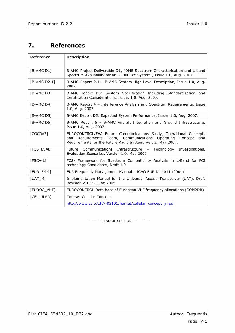
Report number: D 2.2 Issue: 1.0
File: CIEA15EN502_10_D22.doc Author: Frequentis
Page: 7-1
7. References
Reference Description
[B-AMC D1] B-AMC Project Deliverable D1, "DME Spectrum Characterisation and L-band Spectrum Availability for an OFDM-like System", Issue 1.0, Aug. 2007.
[B-AMC D2.1] B-AMC Report 2.1 � B-AMC System High Level Description, Issue 1.0, Aug. 2007.
[B-AMC D3] B-AMC report D3: System Specification Including Standardization and Certification Considerations, Issue. 1.0, Aug. 2007.
[B-AMC D4] B-AMC Report 4 � Interference Analysis and Spectrum Requirements, Issue 1.0, Aug. 2007.
[B-AMC D5] B-AMC Report D5: Expected System Performance, Issue. 1.0, Aug. 2007.
[B-AMC D6] B-AMC Report 6 � B-AMC Aircraft Integration and Ground Infrastructure, Issue 1.0, Aug. 2007.
[COCRv2] EUROCONTROL/FAA Future Communications Study, Operational Concepts and Requirements Team, Communications Operating Concept and Requirements for the Future Radio System, Ver. 2, May 2007.
[FCS_EVAL] Future Communications Infrastructure � Technology Investigations, Evaluation Scenarios, Version 1.0, May 2007
[FSCA-L] FCS- Framework for Spectrum Compatibility Analysis in L-Band for FCI technology Candidates, Draft 1.0
[EUR_FMM] EUR Frequency Management Manual � ICAO EUR Doc 011 (2004)
[UAT_M] Implementation Manual for the Universal Access Transceiver (UAT), Draft Revision 2.1, 22 June 2005
[EUROC_VHF] EUROCONTROL Data base of European VHF frequency allocations (COM2DB)
[CELLULAR] Course: Cellular Concept
http://www.cs.tut.fi/~83101/harkat/cellular_concept_jn.pdf
----------- END OF SECTION -----------
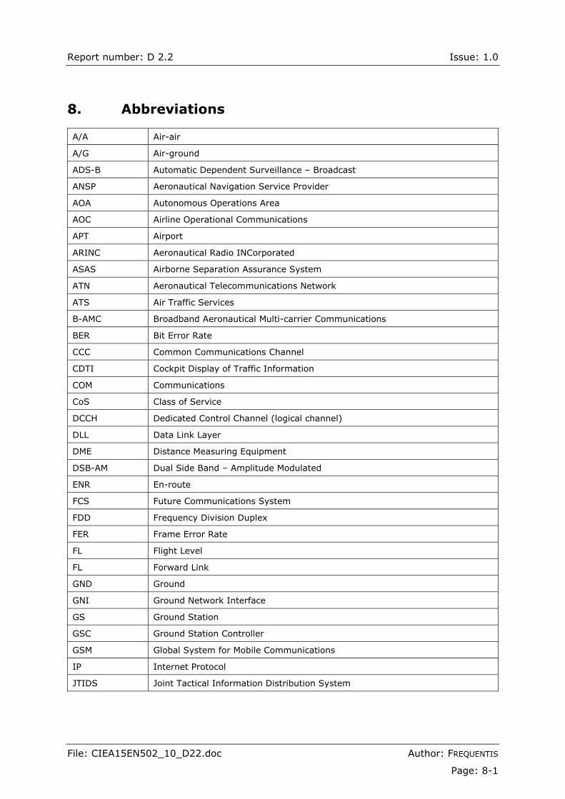
Report number: D 2.2 Issue: 1.0
File: CIEA15EN502_10_D22.doc Author: FREQUENTIS
Page: 8-1
8. Abbreviations
A/A Air-air
A/G Air-ground
ADS-B Automatic Dependent Surveillance � Broadcast
ANSP Aeronautical Navigation Service Provider
AOA Autonomous Operations Area
AOC Airline Operational Communications
APT Airport
ARINC Aeronautical Radio INCorporated
ASAS Airborne Separation Assurance System
ATN Aeronautical Telecommunications Network
ATS Air Traffic Services
B-AMC Broadband Aeronautical Multi-carrier Communications
BER Bit Error Rate
CCC Common Communications Channel
CDTI Cockpit Display of Traffic Information
COM Communications
CoS Class of Service
DCCH Dedicated Control Channel (logical channel)
DLL Data Link Layer
DME Distance Measuring Equipment
DSB-AM Dual Side Band � Amplitude Modulated
ENR En-route
FCS Future Communications System
FDD Frequency Division Duplex
FER Frame Error Rate
FL Flight Level
FL Forward Link
GND Ground
GNI Ground Network Interface
GS Ground Station
GSC Ground Station Controller
GSM Global System for Mobile Communications
IP Internet Protocol
JTIDS Joint Tactical Information Distribution System
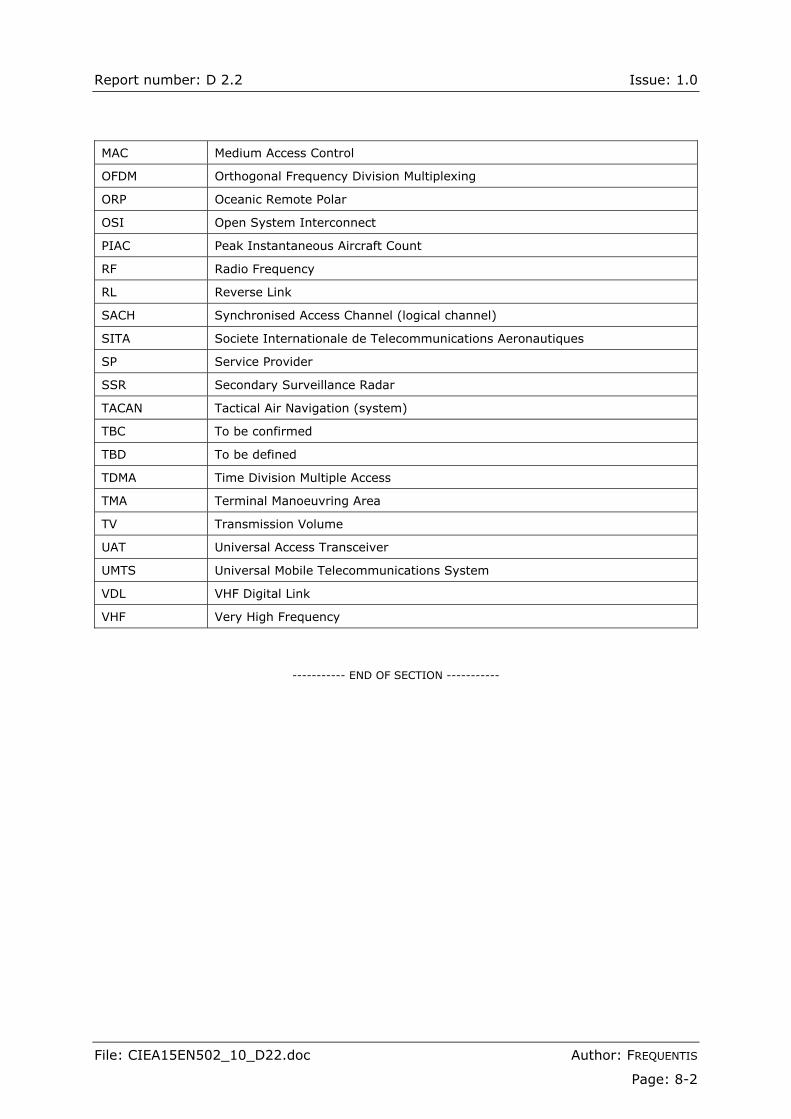
Report number: D 2.2 Issue: 1.0
File: CIEA15EN502_10_D22.doc Author: FREQUENTIS
Page: 8-2
MAC Medium Access Control
OFDM Orthogonal Frequency Division Multiplexing
ORP Oceanic Remote Polar
OSI Open System Interconnect
PIAC Peak Instantaneous Aircraft Count
RF Radio Frequency
RL Reverse Link
SACH Synchronised Access Channel (logical channel)
SITA Societe Internationale de Telecommunications Aeronautiques
SP Service Provider
SSR Secondary Surveillance Radar
TACAN Tactical Air Navigation (system)
TBC To be confirmed
TBD To be defined
TDMA Time Division Multiple Access
TMA Terminal Manoeuvring Area
TV Transmission Volume
UAT Universal Access Transceiver
UMTS Universal Mobile Telecommunications System
VDL VHF Digital Link
VHF Very High Frequency
----------- END OF SECTION -----------