replacing a 2000 honda insight's motor current … a 2000 honda insight's motor ... all...
TRANSCRIPT

Replacing a 2000 Honda Insight's Motor Current Sensors(DTC # P1585, IMA flash code #30, or Check Engine flash code #69)
All three of these codes indicate the same problem, one or more failed motor current sensors, located back in the IMA box, on the left side, inside the PCU (power control unit) along with the DC-DC converter. It's seldom that a car will give you three forms of confirmation on a problem! The check engine light stayed on, along with the IMA light. And all of the IMA functions (charge-discharge, instant start, auto-stop, and the torque boost) were non-functional. The car would start using its 12-volt starter and the DC-DC converter still charged the 12-volt battery.
First I removed the positive 12-volt battery terminal under the hood. Next I opened up the IMA box andchecked all of the low-voltage connections to the MCM (motor control module) computer on the right side by simply unplugging them and plugging them back in repeatedly. I hooked up the 12-volt battery and tested it but still got the same codes.
I tried the same with the wire harness going into the top front of the PCU, but testing gave the same result. Finally I replaced both the MCM and BCM (battery condition module) computers with working extras I had on hand. Still no fix! Looking up the cost of three motor current sensors, the best price wasfrom "Honda Village" in Newton, Massachusetts, for about $64 each, plus shipping. I ordered the parts.
This is a series of photos I took as I disassembled the PCU:
Here is the opened IMA box with the PCU on the left. I removed the left foam cover so it's more visible. Before I proceeded I disconnected the 12-volt battery positive terminal under the hood and switched off the main IMA breaker switch (center).
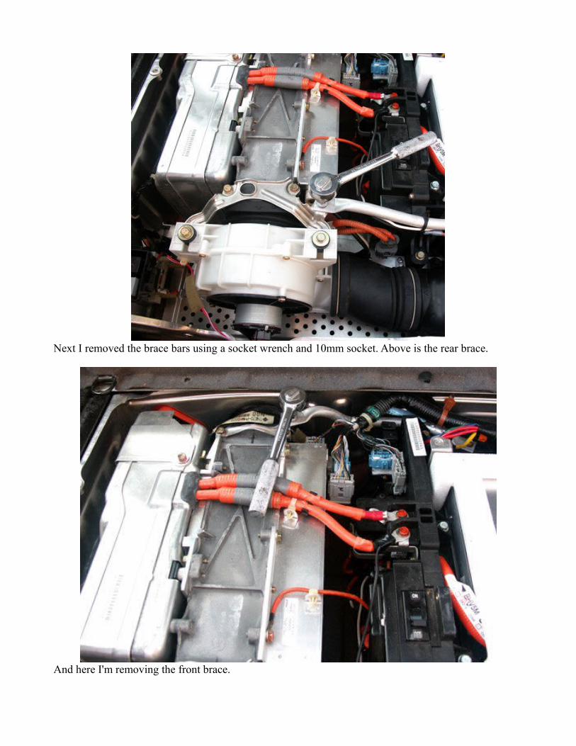
Next I removed the brace bars using a socket wrench and 10mm socket. Above is the rear brace.
And here I'm removing the front brace.

Then I removed the two orange 10mm main power connector bolts. This is the negative coming off. Note that it has a smaller black wire attached. This was added, along with a white wire going to the IMA battery, to allow me to trickle-charge the IMA battery with a high-voltage PV solar array.
And here the positive is being removed. When finished it's best to wrap the two wire ends separately soany energy left in the PCU's capacitors don't cause any sparks.

A flat-tip screwdriver is stuck between the metal and plastic tabs so that the relay harness can be separated from the IMA box.
And these plastic inserts are pried up to allow removal of the left-side foam insert, giving you access to two white plastic locking tabs that hold the wires going to the relay harness.
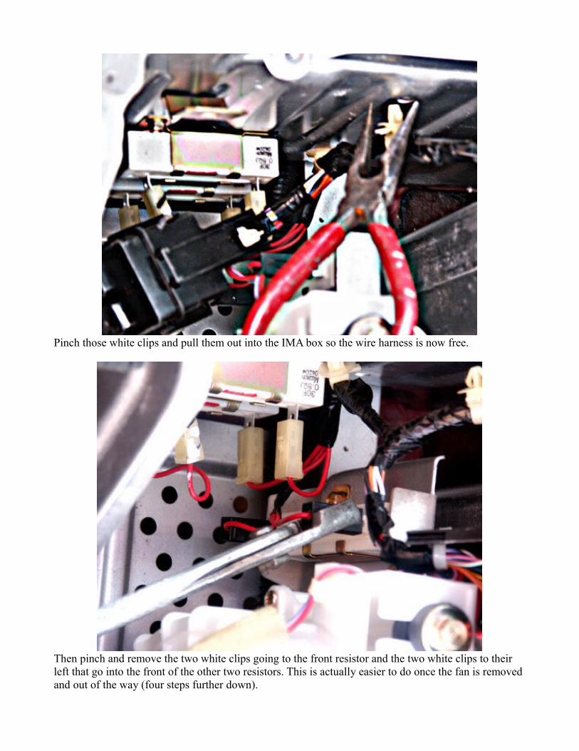
Pinch those white clips and pull them out into the IMA box so the wire harness is now free.
Then pinch and remove the two white clips going to the front resistor and the two white clips to their left that go into the front of the other two resistors. This is actually easier to do once the fan is removed and out of the way (four steps further down).

Next pinch and remove the fan wire.
Pinch and remove the wire clip holding that wire to the fan housing.

Then remove the two 10mm bolts holding the fan housing.
Stick a screwdriver under the hose retainer spring on the right and the whole fan assembly will pull back, upward, and out of the way.

Now that the fan is gone you can remove the two 10mm bolt connections to the 12-volt battery, which you disconnected at the beginning so that no sparks would occur at this point. The first is the top bolt for the negative connection (no boot, black wire). The next to go is the red wire with the red boot, which is the positive.
Then use a flat screwdriver and pliers to yank out the main battery connector to the DC-DC converter. It's usually a hard pull, so don't worry about the effort involved.
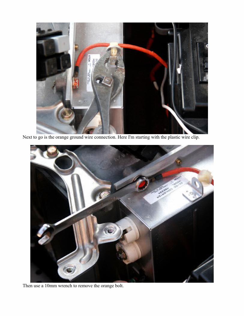
Next to go is the orange ground wire connection. Here I'm starting with the plastic wire clip.
Then use a 10mm wrench to remove the orange bolt.

Next are the low-voltage sensor connectors to the PCU, at the top-front and top-side of the PCU. Pinch the center tabs and pull all three out.
Now remove the 10mm PCU wire cover bolt.

On the left side you'll also see a small black plastic tab that must be pulled out to the left. Then the cover comes off revealing the three high-voltage wires from the electric motor. The 10mm socket is positioned to remove the bottom one of these. Remove all three bolts holding the wire terminals.
And there are two 10mm bolts that hold a steel retainer that locks the three motor wires in place. The wrench is getting the top one and just below it you can see by the hole that the bottom one is already removed. Pull the retainer out and the three wires are free.
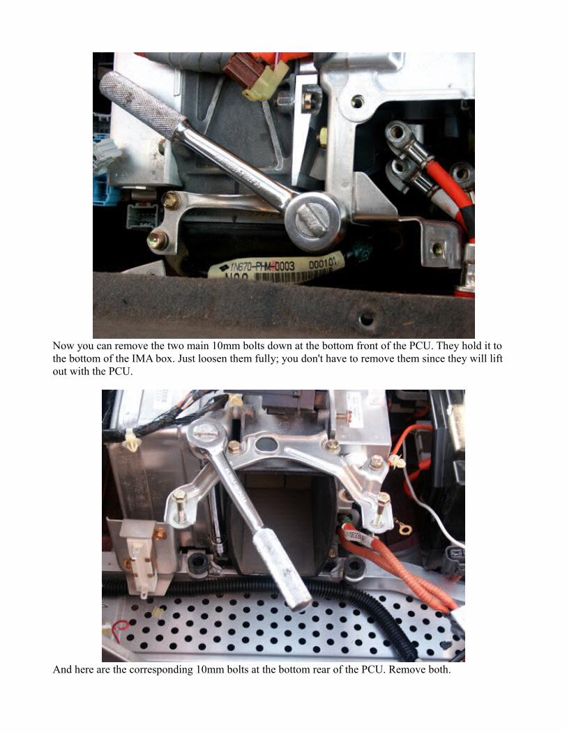
Now you can remove the two main 10mm bolts down at the bottom front of the PCU. They hold it to the bottom of the IMA box. Just loosen them fully; you don't have to remove them since they will lift out with the PCU.
And here are the corresponding 10mm bolts at the bottom rear of the PCU. Remove both.

Wiggle the PCU around, as you pull back to detach the front air duct, and you'll feel the PCU come loose. Carefully, lift it up and out. It doesn't weigh much but it might help to alternate lifting from the drivers seat area and the back hatch.
Now that it's out of the car you'll see this cover on the left side of the unit. The two black 8mm bolts need to be removed.

You'll also see another black 8mm bolt of the front of that cover that has to be removed.
And there are some white clips that hold the black wiring harness going to the main body of the PCU. It'll make life easier if you pinch and remove any of these that help to pull the cover off out of the way.

Slip out the big square black wire seal that covers the square hole in the cover and it will easily lift away from the body of the PCU.
Now you can see what needs to be replaced, the three little gray boxes with the three-wire low-voltage connectors.

And these are the three replacement current sensor modules.
Each one has two 8mm bolts that hold it to the PCU, one low-voltage connector, and one black 8mm bolt that hold its corresponding high-amp aluminum conductor strip to the PCU. Start with the top sensor, then do the bottom, and finish with the middle one to make bolt access easier. The middle one isthe hardest to remove since its high-amp conductor strip has to be twisted around a bit until you figure out how it comes out. As you remove them, keep each strip with its sensor so you can remember how itall goes back together.

It also helps to pull one of the low-voltage connectors from the PCU (second from the bottom) that keeps a big wire bundle in your way. And there's a wire clip for it on the bottom sensor. Remember to keep the steel clip tab and 8mm bolt for that with the bottom sensor so you remember to put it back on.
At this point the top sensor is out and I'm removing the black 8mm bolt that holds the center sensor's high-amp connector strip. Remove the bottom sensor next and access to the middle one's mounting bolts is easier.

Here I'm removing another plastic wire bundle clip and taking off the bottom sensor.
This shows all of the sensors removed and laid out with their corresponding high-amp strips. Just replace each strip in a new sensor, keeping the same orientation, and all will go back together easily, starting with the middle sensor. Replace all three and just reverse all of the previous steps. Rubbing a little dish soap on the interior of the rubber air ducts and using a flat screwdriver to stretch the wire retainer springs helps in slipping them back together as the PCU goes back into the IMA box, and as the fan gets reattached to the battery box duct.
When I had everything put back together I switched on the main IMA breaker and reattached the 12-volt battery positive cable. When I turned the key-switch to ON no IMA or Check Engine trouble lightslit. And when I turned it to START, the instant-start function worked and the charge indicator showed a small charge rate. The battery level read zero bars but it takes about 2 minutes of normal driving for theMCM computer to recalibrate. No more DTCs and no more flash codes. All is well again!

Some might ask, "Since you had the unit apart anyway, why didn't you try to figure out which sensor went bad and just replace that one?" Good question! I tried to diagnose each one, running a high-amp battery wire on my old G.E. Elec-Trak garden tractor through the sensor slot and starting up its mower to surge some amps through the wire. The trouble is that there was no corresponding voltage surge on any combination of the three low-voltage sensor wires.
It appears that you need to send 5 volts of correct polarity DC into the sensor to make it output a signal,and the exact details of how to connect that aren't in the Honda Service Manual. My wife, Larisa, suggested I replace one at a time until the IMA system worked. I disassembled and reassembled it once (so we could drive it) to attempt individual sensor diagnosis before I broke down and ordered all three sensors. Having just disassembled a PCU you now know how much work it is. Imagine doing it severaltimes, working for hours just to save a little cash. The reason the diagnosis of the sensor isn't in the Honda manual is probably because if one sensor goes, another won't be far behind it!
However, once I completed the sensor replacement I decided to give diagnosis another try. The Honda manual didn't mention which pin on the sensor corresponded to a colored wire in their wiring diagrams.But popping the cover off a sensor turned out to be simple - just 2 locking tabs on either side that a thinknife easily pries out.
I marked the correct voltages on the cover I removed once I could see the labels on the PC board.
You can see them at the bottom left: VCC is +5 volts fed into it, GND is the negative for both signal injection and testing the output, and OUT is the positive test point.

I sent 5.11 volts into each sensor using two AA batteries, one a NiMH and the other a rechargeable lithium, stacked in series. Using insulated alligator clips from the batteries to the VCC and GND terminals, I tested the + output on OUT, which is supposed to be around 2.5 volts. Two of the sensors had readings of 2.09 and 2.12 volts, but the third was 3.88 volts. I'm guessing that's the bad one. So I suppose I have two left for possible replacements if this ever happens again.
Larisa also thinks that something about the way she drove the car might have caused the sensor breakdown. There were three instances where she approached a corner at under 19 mph and the auto-stop function engaged as usual. But she shifted into second gear instead of first, since the stoplight went green while her speed was still above 15 mph, and instant start engaged to restart the engine.. Within less than 10 seconds the IMA light came on, but all of the IMA functions (instant start, auto-stop, charge-discharge, and torque boost) worked normally. She simply reset the IMA code when the car was parked and everything was fine again (using the fuse disconnect switch we installed on the dash). On the third occasion, both the IMA and Check Engine lights came on and none of the IMA functions worked again. Was this just a coincidence or does the MCM really dislike going into a second-gear instant start after an auto-stop?