repairing fatigue cracks in a steel deck … in girders g1 and g7 at the supports field...
TRANSCRIPT
REPAIRING FATIGUE CRACKS IN A STEEL DECK PLATE GIRDER
BRIDGE OF UNUSUAL STRUCTURE
Haruhiko Nakata1, Yoshiyuki Takamura
1, Ken Tokumasu
2
Abstract
Morinomiya section of the Hanshin Expressway Higashi Osaka Route (#13)
was opened to traffic in 1978. In October 2010 significant fatigue cracks were found in
some main girder support areas of a three-span continuous steel deck plate girder
bridge in this section. These cracks were found to have initiated in weld beads on the
sole plate or around the bearing set bolts and propagated partly into the webs in only
four years. This paper identifies damage cause through structural analysis and field
measurement and presents an emergency repair measure which takes into account ease
of operation and fatigue durability.
Introduction
A three-span continuous plate girder bridge with steel decks (spans: 9.8 m +
10.0 m + 9.8 m; total width: 16.0 m) on the Hanshin Expressway Higashi Osaka Route
(#13) was found to have fatigue cracks in some main girder support areas in 1993 after
15 years of service. They were repaired by patching, and old steel bearings were
replaced with rubber ones. However, fatigue cracks were again found in the main
girder support areas in October 2010. Cracks originating at weld beads on the sole plate
or around the bearing set bolts were found penetrating through the bottom flange of the
main girder or end cross beam and propagating partly further into the webs. Since no
cracks were found during the latest inspection in 2006, these fatigue cracks were
thought to have initiated and propagated in about four years. It was decided to take
immediate measures to prevent possible rapid growth of these cracks.
Structural overview
The bridge with the fatigue cracks is a part of a bridge system consisting of
simple or continuous plate girder steel deck bridges. The steel deck plate girder type
was selected for its light weight because this section passing over the ruins of the
ancient NANIWA PALACE SITE needed to be designed to protect architectural
remains of the palace.
The Higashi Osaka Route is a heavy traffic road connecting Osaka City area
and its eastern suburb of Higashi Osaka, travelled by about 85,000 vehicles per day on
average, including 17,800 heavy vehicles which account for about 20%.
The superstructure of this bridge is larger in width (16 m) than in span length
(10 m) and, therefore, has a very limited girder height of 700 mm. The bottom flanges
of main girders and those of end cross beams are on the same plane and connected to 1 Hanshin Expressway Engineering Company Limited, Osaka, Japan
2 Hanshin Expressway Company Limited, Osaka, Japan

each other by welding, which inevitably results in a low fatigue strength.
This bridge has an unusual structure in which only three of seven main girders
are supported by bearings.
FIGURE 1 SIDE VIEW OF THE WHOLE BRIDGE SYSTEM
The fatigue cracks were found in girders G1 and G7 at the end support (P187-1)
of the three-span continuous steel deck plate girder bridge which was located on the
west-end side of this section.
FIGURE 2 SECTIONAL VIEW OF THE SUPERSTRUCTURE
Inspection and repair histories
Every route of the Hanshin Expressway is inspected routinely and periodically
for proper maintenance. Periodic inspection is primarily a visual examination from a
close distance and is conducted every five to eight years. Routine inspection is
conducted six times a year by primarily observing the structure at a distance from the
ground using a binocular.
The first periodic inspection on the bridge in this report was performed in 1987
after nine years of service. The bridge then underwent five more periodic inspections
by the end of 2006 and was found to have some damage at every close-up examination.
Table 1 shows a list of years of periodic inspections and damage found during
each inspection.
Damaged
Damaged Damaged

TABLE 1 PERIODIC INSPECTION AND DAMAGE HISTORIES Year of periodic
inspection
Years in
service Damage in girder G1 and repairs Damage in girder G7
1978 -- Opened to traffic.
No damage was
found.
1987 9 years No damage was found.
1991 13 years
Cracks in welds between the sole plate and the main girder
bottom flange
Cracks in the main girder and end cross beam bottom flanges
These cracks were repaired and bearing replacement was
implemented in 1993.
1996 18 years Movements of the bearings
Gap between the top shoe and the rubber
2004 26 years Same as above.
2006 28 years Movements of the bearings
Gap between the top shoe and the sole plate
Damage was first found in 1991 after 13 years of service when fatigue cracks
were detected in girder G1 in a support area. Cracks originating at weld beads between
the sole plate and main girder bottom flange or around the bearing set bolts were found
propagating toward the edge of the main girder bottom flange. These fatigue cracks
were welded and patched for repair, and the existing bearings were replaced with new
ones.
Main girder damage was found only in 1991, and other defects detected during
periodic inspections included movements of the bearings.
No damage has been detected in Girder G7 which was found in healthy state
during periodic inspection in 2006.
Field investigation
Damage in girders G1 and G7 at the supports
Field investigation was carried out by close-up visual examination. Magnetic
particle testing was also performed to obtain accurate locations of the cracks.
Cracks in girder G1 initiated in weld beads between the sole plate and the end
cross beam bottom flange and grew penetrating through the flange and partly
propagating further into the weld between the flange and the web of the end cross beam.
Cracks were also found in the main girder bottom flange, originating at around the
bearing set bolt. None of them was propagating into the main girder web which had a
patch plate on it.

PHOTO 1 CRACKS IN GIRDER G1
Cracks in girder G7 initiated in weld beads between the sole plate and the main
girder bottom flange and penetrated through the flange. They propagated into the weld
between the flange and the web of the main girder, and partly further into the web.
Gap was found between the sole plate and the top shoe in both girders G1 and
G7. The girders were found to move in the vertical direction with every passage of
vehicle, generating metal sound.
PHOTO 2 CRACKS IN GIRDER G7
Other damage
Beside fatigue cracks, shoe base mortar was found damaged on girders G1 and
G4. There was corrosion in the main girders due to leakage of water from the expansion
joints, but without any reduction in cross-section. No cracks were found in the
longitudinal ribs or deck plates of the steel decks.
Checking surface height differences at expansion joints
The vertical movements of girders G1 and G7 with the passage of vehicles
suggested the presence of surface height differences at the expansion joints between
the longitudinally adjacent girders. Road surface was investigated at the expansion
joints, and it was found that there were surface differences of 12 mm and 8 mm,
Patch
plate
respectively, in the west-bound lanes (in the side of girder G7) and in the east-bound
lanes (in the side of girder G1).
Heights of girders G1 and G7 were adjusted in an attempt to eliminate surface
height differences. However, jacking up girder G1 made girder G7 lower, and jacking
up girder G7 made girder G1 lower. Such behavior like a balancing toy suggested that
the superstructure was in an unstable state balancing on a fulcrum at girder G4.
Damage cause estimation
Process from damage cause estimation to emergency repair decision
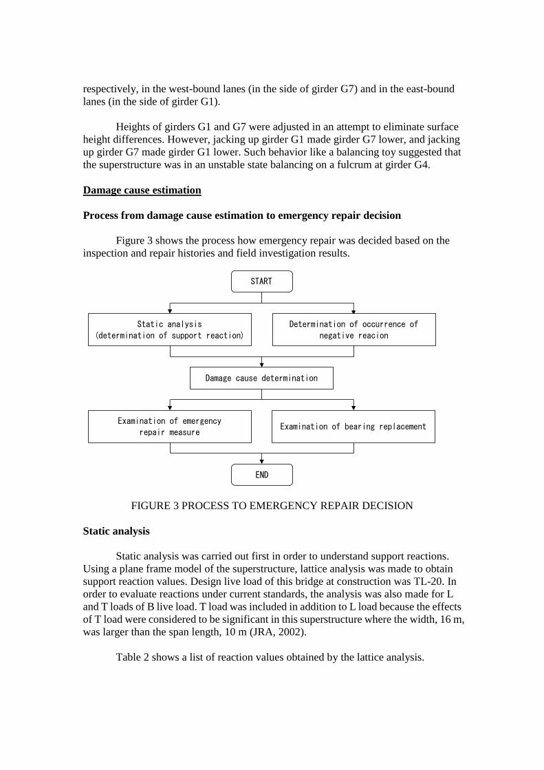
Figure 3 shows the process how emergency repair was decided based on the
inspection and repair histories and field investigation results.
FIGURE 3 PROCESS TO EMERGENCY REPAIR DECISION
Static analysis
Static analysis was carried out first in order to understand support reactions.
Using a plane frame model of the superstructure, lattice analysis was made to obtain
support reaction values. Design live load of this bridge at construction was TL-20. In
order to evaluate reactions under current standards, the analysis was also made for L
and T loads of B live load. T load was included in addition to L load because the effects
of T load were considered to be significant in this superstructure where the width, 16 m,
was larger than the span length, 10 m (JRA, 2002).
Table 2 shows a list of reaction values obtained by the lattice analysis.
START
Static analysis
(determination of support reaction)
Determination of occurrence of
negative reacion
Damage cause determination
Examination of emergency
repair measure
END
Examination of bearing replacement
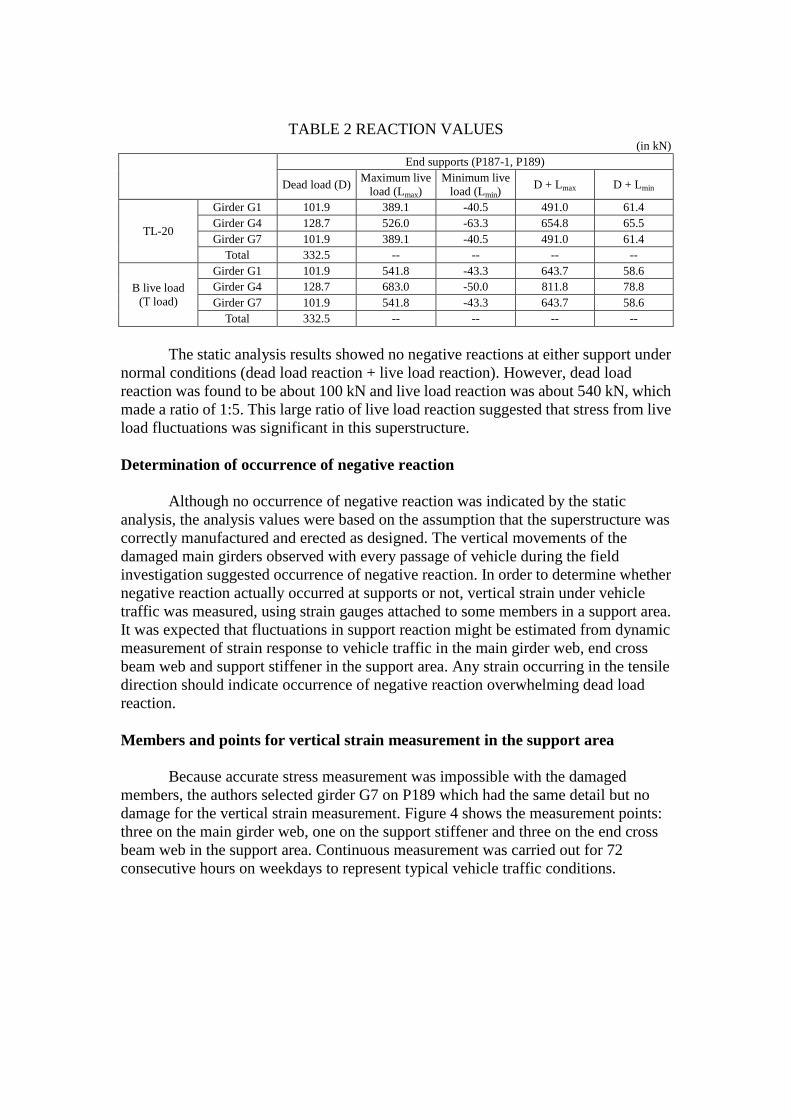
TABLE 2 REACTION VALUES (in kN)
End supports (P187-1, P189)
Dead load (D) Maximum live
load (Lmax)
Minimum live
load (Lmin) D + Lmax D + Lmin
TL-20
Girder G1 101.9 389.1 -40.5 491.0 61.4
Girder G4 128.7 526.0 -63.3 654.8 65.5
Girder G7 101.9 389.1 -40.5 491.0 61.4
Total 332.5 -- -- -- --
B live load
(T load)
Girder G1 101.9 541.8 -43.3 643.7 58.6
Girder G4 128.7 683.0 -50.0 811.8 78.8
Girder G7 101.9 541.8 -43.3 643.7 58.6
Total 332.5 -- -- -- --
The static analysis results showed no negative reactions at either support under
normal conditions (dead load reaction + live load reaction). However, dead load
reaction was found to be about 100 kN and live load reaction was about 540 kN, which
made a ratio of 1:5. This large ratio of live load reaction suggested that stress from live
load fluctuations was significant in this superstructure.
Determination of occurrence of negative reaction
Although no occurrence of negative reaction was indicated by the static
analysis, the analysis values were based on the assumption that the superstructure was
correctly manufactured and erected as designed. The vertical movements of the
damaged main girders observed with every passage of vehicle during the field
investigation suggested occurrence of negative reaction. In order to determine whether
negative reaction actually occurred at supports or not, vertical strain under vehicle
traffic was measured, using strain gauges attached to some members in a support area.
It was expected that fluctuations in support reaction might be estimated from dynamic
measurement of strain response to vehicle traffic in the main girder web, end cross
beam web and support stiffener in the support area. Any strain occurring in the tensile
direction should indicate occurrence of negative reaction overwhelming dead load
reaction.
Members and points for vertical strain measurement in the support area
Because accurate stress measurement was impossible with the damaged
members, the authors selected girder G7 on P189 which had the same detail but no
damage for the vertical strain measurement. Figure 4 shows the measurement points:
three on the main girder web, one on the support stiffener and three on the end cross
beam web in the support area. Continuous measurement was carried out for 72
consecutive hours on weekdays to represent typical vehicle traffic conditions.

FIGURE 4: STRAIN MEASUREMENT LOCATIONS AND POINTS
Results on occurrence of reaction
Figure 5 shows stress waveforms under vehicle traffic obtained from the
vertical strain measurements in the support area. As shown here, no negative reaction
occurred with the passage of vehicle. There was a slight stress in the tensile direction at
point S-6 on the end cross beam, which was attributed to the wheel load on the
overhang causing the backup plate of bracket to uplift.
FIGURE 5 STRESS WAVEFORMS UNDER VEHICLE TRAFFIC
Stress due to live load
Main girder web(end)S-3
(-70mm)
Stress due to live load
End cross beam webS-4
(-40mm)
Stress due to live load
End cross beam webS-6
(-300mm)
Stress due to live load
Support stiffenerS-7
(42.5mm)
-100
-50
0
50
4 4.2 4.4 4.6 4.8 5 5.2 5.4 5.6 5.8
Str
ess
(N/m
m2)
Time (s)
-100
-50
0
50
4 4.2 4.4 4.6 4.8 5 5.2 5.4 5.6 5.8
Str
ess
(N/m
m2)
Time (s)
-50
0
50
100
4 4.2 4.4 4.6 4.8 5 5.2 5.4 5.6 5.8
Str
ess
(N/m
m2)
Time (s)
-100
-50
0
50
4 4.2 4.4 4.6 4.8 5 5.2 5.4 5.6 5.8
Str
ess
(N/m
m2)
Time (s)
S W W

Damage cause estimation
The static analysis and stress measurement revealed no occurrence of negative
reaction in the support areas. Therefore, it was concluded that what caused the damage
was not an uplift of the girders due to negative reaction.
The focus was then moved to the damage to the shoe base mortar on girders G1
and G4. The assumption was that deterioration of the shoe base mortar with time
caused settlement of the bearings, which resulted in vertical movements of the main
girders, giving impacts to the damaged parts (Figure 6).
FIGURE 6: COURSE OF DAMAGE EVOLUTION
Emergency repair measure
Examination of emergency repair measure
The fact that the cracks found in the main girders in the support areas grew in a
very short period indicated an urgent need for some action. It was decided to carry out
emergency repair as an immediate measure. There were two plans for emergency
repair: (1) patching; and (2) partial replacement. Replacement of bearings was also
taken into account because of the damage to the shoe base mortar of girders G1 and G4.
Through a comparative examination, the partial replacement plan was selected to take
advantage of complete removal of cracks which could eliminate possible future
concerns and provide improved fatigue durability to the structure.
Table 3 shows a comparative table of the two plans.
High tension bolts were selected for the connection of parts, while field welding
was also possible. The repair work needed to be carried out while the expressway was
open to traffic, and the headway available for work space was very limited. Field
welding under such conditions was considered to be difficult, especially in terms of
quality control. In addition, the large stress amplitude due to live load might cause
Shoe base mortar damaged due
to determination with time.
Main girders moved vertically
at the support with the
passege of vehicles.
Bearings settled.
Cracks initiated in the main
girders at the support.
Gap was generated between the
sole plate and top shoe.

damage to the new weld in future. In contrast, high tension bolts were considered to be
easy to install even under normal traffic and capable of providing more secure
connection than field welding.

TABLE 3 EMERGENCY REPAIR MEASURE COMPARATIVE TABLE PLAN 1: PATCHING PLAN 2: PARTIAL REPLACEMENT
Schematics
Description
Patch plates are fitted to the main
girder web, end cross beam web
and their bottom flanges to cover
the cracks.
Cracks remain as they are.
Parts with cracks are removed, and
new shop-manufactured parts are
installed.
Cracks are removed completely.
Structure
Fatigue durability does not
change.
Cracks are removed, leaving no
concerns about their growth.
Fatigue durability increases as
the main girder and end cross
beam bottom flanges are
unified in the new part.
Ease of
operation
Work under normal traffic is
possible.
Work period is shorter than
Plan 2.
Limited headway makes the
work difficult.
Work under normal traffic is
possible.
Removal of the parts with
cracks requires a longer work
period.
Limited headway makes the
work difficult.
Economics Economic efficiency is high. Economic efficiency is low.
Maintenance
Existing cracks may grow in
future.
Existing cracks cannot be
monitored because a check
hole cannot be made in the
patch plate.
Increased fatigue durability
due to the replacement
provides excellent maintenance
properties.
Overall
evaluation
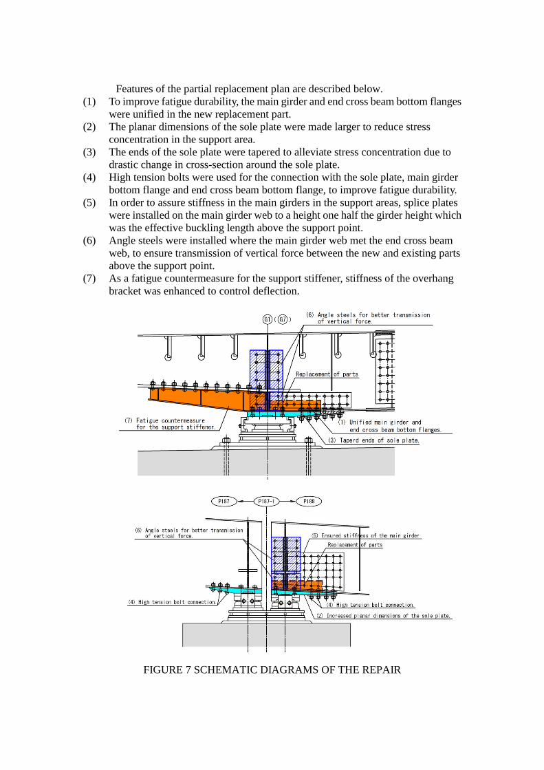
Features of the partial replacement plan are described below.
(1) To improve fatigue durability, the main girder and end cross beam bottom flanges
were unified in the new replacement part.
(2) The planar dimensions of the sole plate were made larger to reduce stress
concentration in the support area.
(3) The ends of the sole plate were tapered to alleviate stress concentration due to
drastic change in cross-section around the sole plate.
(4) High tension bolts were used for the connection with the sole plate, main girder
bottom flange and end cross beam bottom flange, to improve fatigue durability.
(5) In order to assure stiffness in the main girders in the support areas, splice plates
were installed on the main girder web to a height one half the girder height which
was the effective buckling length above the support point.
(6) Angle steels were installed where the main girder web met the end cross beam
web, to ensure transmission of vertical force between the new and existing parts
above the support point.
(7) As a fatigue countermeasure for the support stiffener, stiffness of the overhang
bracket was enhanced to control deflection.
FIGURE 7 SCHEMATIC DIAGRAMS OF THE REPAIR

Figure 7 shows the schematic diagrams of the partial replacement plan. The
numbers in the diagrams correspond to the numbers in the above list. The parts marked
with red color are those to be replaced, and the blue-colored part is the new sole plate to
be installed.
Study on bearing replacement
The damage found in the existing shoe base mortar on girders G1 and G4
suggested influences on the capacity to carry reaction force. On the other hand, the
limited headway required the existing bearings to be temporarily removed for the
emergency repair work to create a sufficient work space. However, fine height
adjustment was difficult with the existing bearing system in which the higher bearing
on the west-end side and the lower bearing on the east-end side were mounted on the
same block, sharing one base plate, one height adjustment plate and one bottom shoe
(Figure 8).
Consequently, it was decided to replace the bearings at the same time with the
emergency repair work. Steel bearings were employed to replace the existing rubber
ones so that reaction force would be carried more properly. In order to make height
adjustment in the field easy, the height adjustment plate was divided into two parts for
the two bearings.
FIGURE 8 SIDE VIEW OF THE EXISTING BEARINGS
There was significant leakage of water from the expansion joints. Rainwater
could have penetrated through the damage in the shoe base mortar, causing corrosion of
the bearing anchor bolts. Ultrasonic measurement was carried out on the existing
bearing anchor bolts, and it was found that their embedment length was about 400 mm
at minimum against 610 mm in as-built drawings.
Since corrosion and possible reduction in cross-section of the existing bearing
anchor bolts were suggested by the measurement results, the existing anchor bolts were
discarded and replaced with new ones for the new bearings.

Conclusions
In this paper damage cause was estimated from structural analysis and field
measurement results, and emergency repair measure was discussed, with fatigue
durability emphasized for the prevention of possible similar problems in future. Key
findings are summarized below.
1) Static analysis revealed that the superstructure was subject to live load effects,
with a ratio of dead load reaction to live load reaction being 1:5.
2) The static analysis and stress measurement revealed no occurrence of negative
reaction. Therefore, it was concluded that what caused the damage was not an
uplift of the girders due to negative reaction.
3) The damage cause was assumed to be impact from vertical movements of the
main girders due to settlement of the bearings caused by deterioration of shoe
base mortar with time.
4) Partial replacement was selected for the emergency repair to take advantage of
complete removal of cracks which could eliminate future concerns about
growing cracks and provide improved fatigue durability to the structure.
5) High tension bolts were used for the connection with the sole plate, main girder
bottom flange and end cross beam bottom flange to improve fatigue durability.
6) The bottom flange of the main girder and that of the end cross beam were unified
in the new replacement part for improved fatigue durability.
7) Although no damage was found in the support stiffener in this study, damage was
detected in other locations with the same detail in other spans. Therefore, fatigue
countermeasure was taken as a preventive maintenance by improving stiffness of
the overhang bracket to control deflection.
8) Bearings were replaced at the same time with the emergency repair work. This
allowed to obtain a sufficient work space in the limited headway, improving ease
of operation.
9) In the new bearing system the height adjustment plate was divided into two parts
for the two bearings on the west- and east-end sides to make height adjustment in
the field easy.
Closing remarks
The emergency repair project described in this paper has just been completed.
Photo 3 shows girder G7 after removal of the damaged parts. Photo 4 shows the same
girder after the partial replacement, with the bearings also replaced.
Stress measurement is planned in the vicinity of the emergency repair site to
evaluate the repair effect by comparing the measurement results with those for other
locations with the same detail but no damage.
This section of the expressway consists of similar structures to this bridge
which is subject to live load effects. Permanent repair including in-depth modification
will be conducted on this section next year.

PHOTO 3 GIRDER G7 IMMEDIATELY AFTER REMOVAL OF THE PARTS
WITH CRACKS
PHOTO 4 GIRDER G7 AT THE COMPLETION OF EMERGENCY REPAIR
References
[1] Japan Road Association (JRA): Specifications for Highway Bridges and
Commentary, Part II Steel Bridges, March 2002.