repair of earthquake-damaged square r/c columns with glass
TRANSCRIPT

1. Introduction
After major earthquakes, many damaged and
undamaged R/C buildings within the affected
region need to be repaired and strengthened
based on more demanding seismic codes.
Furthermore, many existing reinforced
concrete columns were constructed
according to older codes, lack adequate
seismic resistance. These columns were
typically designed for gravity loads and were
often inadequately detailed to resist
earthquake forces in zones of high seismicity.
Most of the columns in older reinforced
concrete buildings can be particularly
vulnerable structural elements due to
inadequate lap splice detailing for the
longitudinal bars. They have also lack of
confinement in flexural hinge zones and
inadequate shear strength.
In addition, field observations in past
earthquakes have revealed that columns with
inadequate compression lap splices and
widely spaced transverse reinforcement
performed poorly, especially those located
along the perimeter of the buildings. This
paper presents the results of an experimental
study on a repairing technique for non-
ductile concrete columns, having inadequate
lap splices for their longitudinal
reinforcement, with GFRP sheets applied in
plastic hinge regions of them.
2. Background and previous research
Past earthquakes including the San Fernando
(California-1971), Loma Prieta (California-
1989), Northridge (California-1994), Kobe
(Japan-1995), Izmit (Turkey-1999), Chichi
(Taiwan-1999), Gujarat (India-2001),
Boumerdes (Algeria-2003) and Bam (Iran-
2003) caused sever damage and collapse of
non-ductile reinforced concrete frames.
210 International Journal of Civil Engineerng. Vol. 5, No. 3, September 2007
Repair of Earthquake-Damaged Square R/C Columns with Glass Fiber-
Reinforced Polymer
Sassan Eshghi1, Vahid Zanjanizadeh2
1Assistant Professor of International Institute of Earthquake Engineering and Seismology(IIEES),
Email: [email protected] 2Graduate Student of International Institute of Earthquake Engineering and Seismology(IIEES),
Email: [email protected]
Abstract:This paper presents an experimental study on seismic repair of damaged square reinforcedconcrete columns with poor lap splices, 90-degree hooks and widely spaced transverse bars inplastic hinge regions according to ACI detailing (pre.1971) and (318-02) using GFRP wraps. Threespecimens were tested in “as built” condition and retested after they were repaired by glass fiber-reinforced plastic sheets. They were tested under numerous reversed lateral cyclic loading with aconstant axial load ratio. FRP composite wraps were used for repairing of concrete columns incritically stressed areas near the column footings. Physical and mechanical properties of compositewraps are described. Seismic performance and ductility of the repaired columns in terms of thehysteretic response are evaluated and compared with those of the original columns. The resultsindicated that GFRP wraps can be an effective repair measure for poorly confined R/C columnsdue to short splice length and widely spaced ties with 90-degree anchorage hooks. Both flexuralstrength and ductility of repaired columns were improved by increasing the existing confinement incritical regions of them.
Keywords: Columns, GFRP, Earthquake Damage, Repair, Hysteretic Response, Ductility
[ D
ownl
oade
d fr
om ij
ce.iu
st.a
c.ir
on
2022
-03-
24 ]
1 / 14

These earthquakes have clearly demonstrated
the vulnerability of non-ductile R/C frames
and the need for their repair and
strengthening.
The most common types of non-ductile
details are short splice length and wide ties
with 90° hooks. These details had led to
considerable damages in recent earthquakes.
Fig.1 and Fig.2 show two-column damage in
Izmit and Northridge earthquakes due to such
detailing.
Since the Loma Prieta 1989 earthquake,
considerable progress has been made by
many institutions such as the California
Department of Transportation in
implementing retrofit measures to upgrade
the seismic resistance of the columns.
Nowadays, the use of FRP sheets for
repairing and strengthening of R/C columns
has become widespread. Several researchers
have investigated the circular, oval, and
rectangular R/C columns and use of fiber
reinforced polymer composite jackets for
seismic strengthening and repair of columns
with deficiencies such as inadequate lap
splice for the longitudinal reinforcement or
lack of the sufficient shear strength [Chai et
al., 1991[4], Marsh, 1992[5], Xiao et al.,
1999[11], Xiao et al.,1997[12], Bayrak et al.,
1997[2], Bayrak et al., 2003[3], and Wallace
et al., 2004[10]].
Chai, et al. investigated the use of fiber
composite wraps for retrofit of the circular
concrete columns and Bayrak et al. and Xiao
et al. studied retrofit of rectangular columns
with CFRP. Marsh examined the use of steel
angle and straps and steel jacketing to
strengthen of rectangular R/C columns with
inadequate lap splices.
Past researches have been extensively
directed toward repair and retrofit of
damaged bridge columns, for instance in [9]
typical damaged bridge R/C columns have
been tested. But, a few researches have been
carried out on the behavior and/or using of
FRP sheets for retrofitting of rectangular R/C
columns of buildings with deficient lap
splices and/or inadequate confinement under
various axial and lateral cyclic loading [3]
[10]. The reported research in this paper,
addresses the repair of damaged square R/C
211International Journal of Civil Engineerng. Vol. 5, No. 3, September 2007
Fig.1 Failure of lap splice due to widely spaced ties with90o hooks (Izmit-1999)
Fig.2 Failure of lap splice due to insufficient splice lengthand widely spaced ties with 90o hooks (Northridge-1994)
[ D
ownl
oade
d fr
om ij
ce.iu
st.a
c.ir
on
2022
-03-
24 ]
2 / 14

columns of buildings with defective detailing
via glass fiber-reinforced wraps.
3. Experimental work
Three R/C columns were severely damaged
as part of research. The columns were cast in
an upright position using normal weight
aggregate concrete, and cured for periods
exceeding 28 days. This experimental
program consisted of the design,
construction, testing of three columns under
cyclic loading, and subsequently repaired
prior to retesting with same loading. The
main variable item was the level of axial load
in all the specimens.
The specimens were cantilever columns with
the fixed end framing into rectangular spread
footings. Two of the specimens had
longitudinal bars with short splice lengths,
widely spaced transverse reinforcement, cut
off more than 50% of the moment capacity of
the section according to ACI (pre.1971). One
of them was in accordance with ACI (318-
02) detailing.
3.1. Specimens
All columns had square cross sections of
150×150-mm, 1000-mm length, reinforced
by 8-mm diameter longitudinal bars. Two of
them have 4-mm ties @150-mm spacing
with 90º hooks according to ACI (pre.1971)
detailing and one of them has 4-mm
ties@60-mm in plastic hinge region and
@150-mm in other sections with 135°hooks
212 International Journal of Civil Engineerng. Vol. 5, No. 3, September 2007
Splice 20 db
%shρLayers of GFRP
Axial load (kN)
P/ f’ c AgSpecimen
No0.644021.20.05SP-S1
Yes0.258021.20.05SP-S2
Yes0.258063.60.15SP-S3
No0.644521.20.05SP-R1
Yes 0.258521.20.05SP-R2
Yes0.258563.60.15SP-R3
Table 1 Detail of test specimens
Fig.3 Specimens reinforcing cage in their formworks Fig.4 Strain gauges were installed on the bars
[ D
ownl
oade
d fr
om ij
ce.iu
st.a
c.ir
on
2022
-03-
24 ]
3 / 14
in accordance with ACI(318-02) detailing.
The lateral load is applied at 800-mm from
the base of column. The specimens represent
columns located in multistory building frame
between of the maximum moment and contra
flexure points. Details of the specimens are
listed in Table 1.
3.2. Material properties
A series of basic tests was carried out to
obtain the mechanical properties of concrete
and reinforcing steel. Reinforcing bars and
GFRP sheet and concrete were tested to
obtain mechanical characteristic of materials.
Grade 400, steel were used for longitudinal
and grade 300 steel for transverse steel bars.
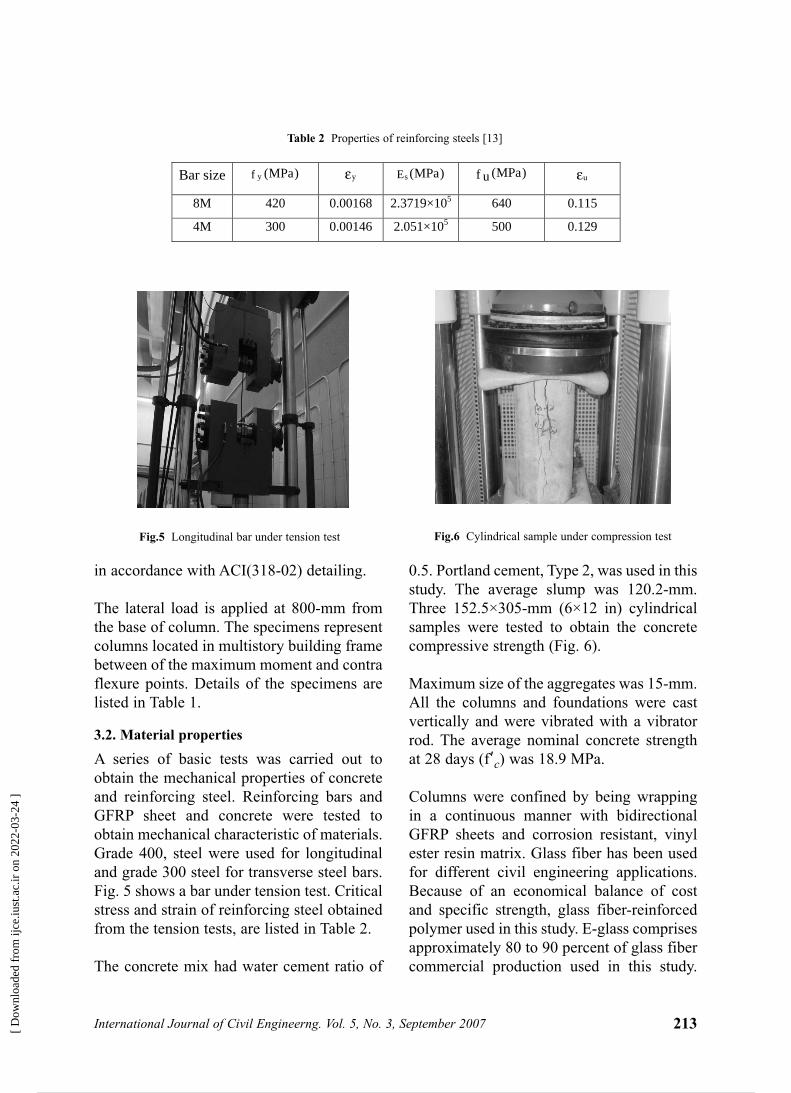
Fig. 5 shows a bar under tension test. Critical
stress and strain of reinforcing steel obtained
from the tension tests, are listed in Table 2.
The concrete mix had water cement ratio of
0.5. Portland cement, Type 2, was used in this
study. The average slump was 120.2-mm.
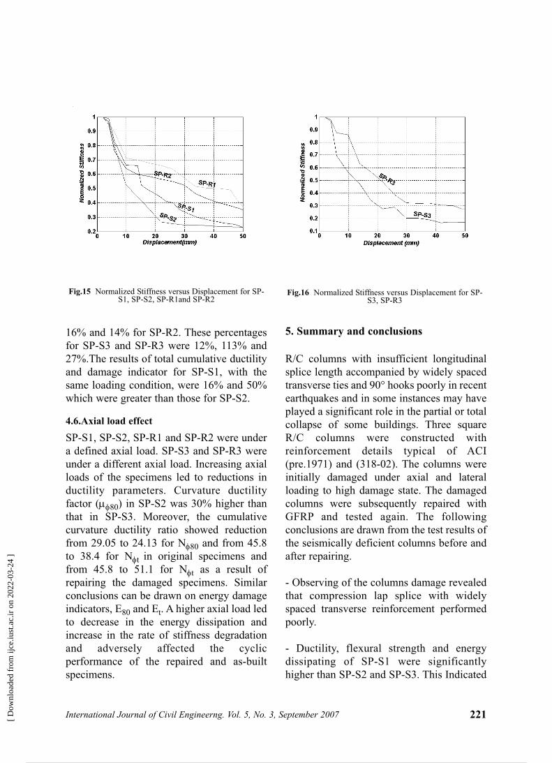
Three 152.5×305-mm (6×12 in) cylindrical
samples were tested to obtain the concrete
compressive strength (Fig. 6).
Maximum size of the aggregates was 15-mm.
All the columns and foundations were cast
vertically and were vibrated with a vibrator
rod. The average nominal concrete strength
at 28 days (fBBc) was 18.9 MPa.
Columns were confined by being wrapping
in a continuous manner with bidirectional
GFRP sheets and corrosion resistant, vinyl
ester resin matrix. Glass fiber has been used
for different civil engineering applications.
Because of an economical balance of cost
and specific strength, glass fiber-reinforced
polymer used in this study. E-glass comprises
approximately 80 to 90 percent of glass fiber
commercial production used in this study.
213International Journal of Civil Engineerng. Vol. 5, No. 3, September 2007
Bar size )MPa(f y εy )MPa(Es )MPa(f u εu
8M 420 0.00168 2.3719×10⁵ 640 0.115
4M 300 0.00146 2.051×10⁵ 500 0.129
Table 2 Properties of reinforcing steels [13]
Fig.5 Longitudinal bar under tension test Fig.6 Cylindrical sample under compression test
[ D
ownl
oade
d fr
om ij
ce.iu
st.a
c.ir
on
2022
-03-
24 ]
4 / 14

The mechanical properties of GFRP
composite and vinyl ester resin are
summarized in Table 3 and 4.
3.3. Reinforcing details
Three specimens have been constructed and
tested. The structural configuration of the
specimens consisted of two parts, a stub cage
and a column cage. They were built
separately and then connected to each other.
Fig. 7 shows the detailing of specimens
reinforcement. Column type C1detailing was
designed according to ACI (pre.1971).
Column type C2 was designed according to
ACI (318-02). Detailing of both types of
footings designed to be strong enough to
prevent cracking.
3.4. FRP Installation
All three specimens in as-built condition
were tested and then were repaired by first
replacing the loosened concrete with quickset
cement then were cleaned with a high
pressure gun and completely dried before the
vinyl ester was applied to their surfaces
(Fig.8). Special measures were taken to
ensure that there were no voids between the
sheets and the concrete surfaces. After the
application of the first layer of the GFRP
sheet, a second layer of vinyl ester sheet was
applied on the surface of the first layer to
allow impregnation of the second layer of the
GFRP sheet.
The wrapping of the columns continued to
the upper region of the column (Fig.9). All
the repaired specimens were cured at least for
7 days to ensure that full strength had
obtained before testing.
3.5.Test setup
Fig.10 illustrated the loading assembly used
to apply the gravity and lateral loads. An
actuator with 50 kN capacity was used to
impose predefined cyclic displacement
routine at top end of the columns. The axial
load was applied with a 250 kN capacity
hydraulic jack. This testing setup was able to
consider the P-∆ effect that might be
experienced in buildings. The bottom of the
specimens were connected and fixed to the
strong floor.
214 International Journal of Civil Engineerng. Vol. 5, No. 3, September 2007
Strain to failure(percent)
Density (N/mm3)
Tensile strength
( MPa)
Tensile modulus
(MPa)
Coefficient of
thermal expansion
10-6/C
4.8 25.5 1750 70000 4.7
Table 3 Mechanical properties of FRP composite
Tensil elongation at break(percent)
Tensile strength
( MPa)
Tensile modulus
(MPa)
Heat distortion
Temperature (C)
5.2 89.6 3171 119
Table 4 Mechanical properties of vinyl ester resin
[ D
ownl
oade
d fr
om ij
ce.iu
st.a
c.ir
on
2022
-03-
24 ]
5 / 14

215International Journal of Civil Engineerng. Vol. 5, No. 3, September 2007
(a) (b)
Fig. 7 Specimens geometry and details (a) Column Type C1 (b) Column Type C2
Fig.8 Cleanig surface of the damaged columns Fig.9 Installation of prefabricated composit sheets
[ D
ownl
oade
d fr
om ij
ce.iu
st.a
c.ir
on
2022
-03-
24 ]
6 / 14

The height of the columns was 1000-mm but
lateral displacement was applied at a height
of 800-mm of the columns.
3.6. Testing procedure and instrumentation
Predefined cyclic lateral displacements with
28 cycles were subjected to specimens while
the axial load was constant at either (0.05f’c
Ag) or (0.15f’c Ag). Each prescribed drift
level repeated twice in order to measure the
strength degradation of the specimens.The
rate of the applied displacement is shown in
Fig. 11.
Each specimen was instrumented to record
various response parameters. Linear Variable
Differential Transformers (LVDT s) were
installed on the specimens to measure the
rotations of the columns relative to footings
and also probable vertical displacements of
the supports and the footings due to the
lateral forces. All specimens were
instrumented with three strain gauges on
rebars (see Fig.4), two strain gauges on the
surface of FRP sheets and two strain gauges
on the surface of the columns, just above the
FRP sheets.
216 International Journal of Civil Engineerng. Vol. 5, No. 3, September 2007
Fig.10 Schematic test setup
Fig.11 Lateral displacement history
[ D
ownl
oade
d fr
om ij
ce.iu
st.a
c.ir
on
2022
-03-
24 ]
7 / 14

4. Test results
Behavior of a specimen under loading, was
graphically represented in the form of a
relationship between the hysteretic moment
and the curvature of the section. Stiffness
degradation and distribution of cracks were
studied in the as built and also the repaired
columns. In each cycle the lateral load and
the deflection at free end of the columns were
recorded and the crack patterns were
registered during the tests.
4.1. Observed damages and behavior
During testing of specimen SP-S1 at 1% drift
ratio, initial flexural cracks were observed at
the column footing interface and at 1.5% drift
ratio the same cracks at the column footing
splice length. Some flexural cracks appeared
along the splice length during the test but the
length and width of these cracks did not
increase significantly (Fig.12a).
In specimen SP-S2 flexural cracks on the
column face started as early as at 1% lateral
drift ratio. At this time longitudinal cracks
were formed at right and left sides of the
specimen. During the second cycle at 3.5%
drift as fairly large sections of the concrete
cover spalled at the column footing interface.
The lateral load strength diminished,
indicating that bond along the spliced bars
was deteriorating. Shear cracking was
observed at 2.5% drift but these cracks were
not significant throughout the test. Damage
in this specimen was severer than that in the
217International Journal of Civil Engineerng. Vol. 5, No. 3, September 2007
����
����
���
���
��
��
��
��
����
����
� S1
� �1
1
1
���������
�� �
���
����
�
�
����
���
� S2
��
2
�2
�
�����
�����
����
���
��
��
��
����
����
�� S
� �3
S3
3
Fig.12 Specimens at end of testing
[ D
ownl
oade
d fr
om ij
ce.iu
st.a
c.ir
on
2022
-03-
24 ]
8 / 14

previous one (Fig.12b).
Specimen Sp-S3 was subjected to a (0.15 Ag
f’c) constant axial load and initial flexural
longitudinal cracks suddenly appeared at
1.5% drift ratio. In this test, cracking formed
later but cracking propagation developed
suddenly as the load applied. In this
specimen the cover spalled completely at the
corner at 4.5% drift ratio and the longitudinal
bars were clearly visible. Along the splice
length, there was severe damage. Shear
cracks were observed at 3.5% drift ratio on
the right and left faces of the columns and
concrete crushing and spalling were observed
just before the end of the test. In this
specimen damage was generally severer than
SP-S1 and SP-S2 (Fig.12c).
Stiffness of the repaired specimens had been
deteriorated under large reversed cyclic
loading. Large amount of the damages were
concentrated in FRP sheets and some small
sheet rupture was observed in high drift ratio.
Damage in the concrete of repaired columns
was slight. Vertical and horizontal flexural
cracking, that occurred above the FRP jacket
in past testing, opened and closed during
retesting. Nevertheless, in the SP-R1,
damage was very low and very little stress
concentration was occurred in FRP sheets.
Some new cracks were observed in all
repaired specimens but they were not
significant. At the end of the test, cracks in all
specimens propagated along the columns but
in SP-R3 the sustained damage was more
serious than two others. Cracks in SP-R1
were little and narrow. During the test, cracks
at the column footing interface of SP-R3
were very serious and some spalling and
crushing were appeared. So it indicated that
high axial load led to more serious damage in
the specimens. SP-R1 behaved better and no
delaminating or rupture across the fibers of
the jackets was observed in this specimen
(Fig.12d, 12e, 12f).
4.2. Moment- curvature response
The total moment at the bottom of the
columns is calculated by summing up the
moments caused by the lateral load and the
vertical load due to lateral displacement as
given by Equation (1), follow as
M=F. h +P∆Lateral. (1)
The curvature values were obtained from
deformation reading at middle of the column
and bottom LVDTs data located at 100-mm
above the column footing interface.
4.3. Ductility and energy dissipation
parameters
To quantify the response of columns under
imposed loads, it is preferred to define the
response indices that can describe their
behavior quantitatively. In most current
seismic design methodologies, the inelastic
deformation is generally quantified by
ductility parameters. Since the member
ductility can not be applied for this series of
displacement control tests, only section
ductility is described. Moment-curvature
diagram and its corresponding ductility
parameters can be utilized to describe the
ductility of the specimens.
Fig.14 describes some ductility parameters
including curvature ductility factor µφ,
cumulative ductility ratio Νφ and energy
damage indicator E. Subscripts t and 80 are
added, respectively, to Νφ, E to indicate the
value of each parameter at two different
occasions: end of the test and end of the cycle
in which the moment is dropped to
approximately 80 percent of the maximum
value. In Fig14, Lf represents the length of
the most damaged region measured during
the test and h represents the depth of the
column section.
218 International Journal of Civil Engineerng. Vol. 5, No. 3, September 2007
[ D
ownl
oade
d fr
om ij
ce.iu
st.a
c.ir
on
2022
-03-
24 ]
9 / 14

219International Journal of Civil Engineerng. Vol. 5, No. 3, September 2007
�����
�
����
����
�� �
��S1
���S
���
1
S3
2
�
����
�
���
����
�����
��S2
��1
��3
2
1
3
Fig.13 Moment –Curvature diagrams of the specimens
[ D
ownl
oade
d fr
om ij
ce.iu
st.a
c.ir
on
2022
-03-
24 ]
10 / 14

The curvature ductility parameters and
energy damage indicator for all the
specimens are listed in Table 5.
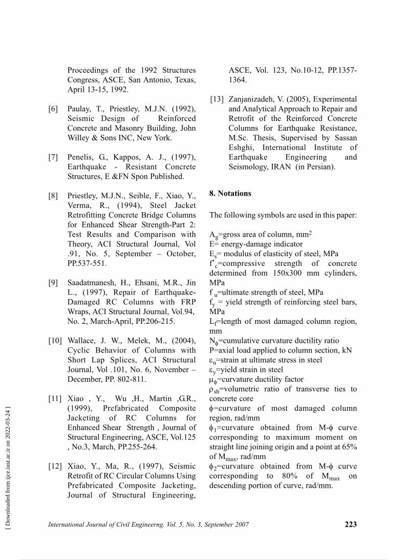
4.4. Stiffness degradation
Stiffness for each cycle was calculated as the
average of the stiffness for the positive and
negative directions. Stiffness for each cycle
was normalized with respect to the stiffness
of the first cycle and was plotted versus the
displacement. Stiffness degradation versus
column top displacement after normalization
is plotted in Fig.15 and Fig.16.
4.5.Effect of GFRP repairing technique on
damaged columns
For assessing a repair technique, a single
parameter criterion can not be adequate in
many cases. Herein, various parameters are
employed to evaluate the applied repairing
method. SP-S2 and SP-R2 have the same
detailing and were subjected to the same
axial loading but SP-R2 was repaired with
GFRP wraps after testing. Experiments
indicated that total cumulative ductility ratio
(Νφt), 80% of energy indicator (E80) and total
energy indicator (Et) were increased by 25%,
220 International Journal of Civil Engineerng. Vol. 5, No. 3, September 2007
Fig.14 Definitions of section ductility parameters
EtE80N tφN 80φµφ80Specimen1180.2+44.6++SP-S1
786.3580.738.429.054SP-S2
423.9165.245.824.133.09SP-S3
1333.21059.855.5++SP-R1
891.9673.559.9++SP-R2
537.2352.651.1++SP-R3
+=moment did not drop to this level
Table 5 Section ductility parameters
[ D
ownl
oade
d fr
om ij
ce.iu
st.a
c.ir
on
2022
-03-
24 ]
11 / 14
16% and 14% for SP-R2. These percentages
for SP-S3 and SP-R3 were 12%, 113% and
27%.The results of total cumulative ductility
and damage indicator for SP-S1, with the
same loading condition, were 16% and 50%
which were greater than those for SP-S2.
4.6.Axial load effect
SP-S1, SP-S2, SP-R1 and SP-R2 were under
a defined axial load. SP-S3 and SP-R3 were
under a different axial load. Increasing axial
loads of the specimens led to reductions in
ductility parameters. Curvature ductility
factor (µφ80) in SP-S2 was 30% higher than
that in SP-S3. Moreover, the cumulative
curvature ductility ratio showed reduction
from 29.05 to 24.13 for Νφ80 and from 45.8
to 38.4 for Νφt in original specimens and
from 45.8 to 51.1 for Νφt as a result of
repairing the damaged specimens. Similar
conclusions can be drawn on energy damage
indicators, E80 and Et. A higher axial load led
to decrease in the energy dissipation and
increase in the rate of stiffness degradation
and adversely affected the cyclic
performance of the repaired and as-built
specimens.
5. Summary and conclusions
R/C columns with insufficient longitudinal
splice length accompanied by widely spaced
transverse ties and 90° hooks poorly in recent
earthquakes and in some instances may have
played a significant role in the partial or total
collapse of some buildings. Three square
R/C columns were constructed with
reinforcement details typical of ACI
(pre.1971) and (318-02). The columns were
initially damaged under axial and lateral
loading to high damage state. The damaged
columns were subsequently repaired with
GFRP and tested again. The following
conclusions are drawn from the test results of
the seismically deficient columns before and
after repairing.
- Observing of the columns damage revealed
that compression lap splice with widely
spaced transverse reinforcement performed
poorly.
- Ductility, flexural strength and energy
dissipating of SP-S1 were significantly
higher than SP-S2 and SP-S3. This Indicated
221International Journal of Civil Engineerng. Vol. 5, No. 3, September 2007
Fig.15 Normalized Stiffness versus Displacement for SP-S1, SP-S2, SP-R1and SP-R2
Fig.16 Normalized Stiffness versus Displacement for SP-S3, SP-R3
[ D
ownl
oade
d fr
om ij
ce.iu
st.a
c.ir
on
2022
-03-
24 ]
12 / 14

that sufficient lap splice length and also
confining of concrete in plastic hinge region
in the R/C. columns improved their seismic
performance significantly.
- Use of the GFRP sheets for repairing of
damaged columns changed the flexural
plastic hinge location from the base of the
columns to a place just above the GFRP
sheets.
- GFRP composite wraps were effective in
restoring the flexural strength, stiffness and
ductility capacity of damaged columns and
enhancing the shear strength and concrete
confinement in the damaged columns.
- In all repaired specimens, the rate of
stiffness deterioration under constant axial
load and reversed cyclic loading was lower
than original columns. However, the initial
stiffness of repaired columns were lower than
of the original columns.
- In all specimens, the rate of degradation
was dependent on the level of the axial
loading and also to the level of the applied
shear force. At high level of axial load
differences in ductility, energy dissipating
and stiffness degradation between the as-
built and repaired columns were
considerable.
- Repaired specimens behavior demonstrated
stable loops in high drift ratios and
performed as a better energy dissipater
compared to the original specimens.
- The repaired columns showed relatively
larger lateral displacements at low load levels
compared to the original columns. This
appeared to be due to pre-existed damage in
the form of bond deterioration between
reinforcing bars and concrete in original
columns and cracks induced during the first
test. However, the lateral strength of the
repaired columns increased compared to the
original columns.
6. Acknowledgements
The authors wish to thank International
Institute of Earthquake Engineering and
Seismology (IIEES) for sponsoring and
supporting the research reported in this paper.
They would also like to acknowledge Ms.
Maedeh Alemi for her technical assistance.
7. References
Aboutaha , R.S., Engelhardt ,M.D.,
Jirsa, J.O., Kreger, M.E., (1996),
Retrofit of Concrete Columns with
Inadequate Lap Splices by the Use of
Rectangular Steel Jackets, Earthquake
Spectra, November ,Vol.12, PP. 693-
715.
Bayrak , O., Sheikh, S. A., (1997),
High-Strength Concrete Columns
under Simulated Earthquake Loading,
ACI Structural Journal, Vol. 94, No. 6,
November- December, PP.708-722.
Bayrak, O., Lacobucci, R.D., Sheikh ,
S. A., (2003), Retrofit of Square
Concrete with Carbon Fiber-
Reinforced Polymer for Seismic
Resistance , ACI Structural Journal
,Vol .100 , No. 6, November-
December ,PP.785-794.
Chai, Y. H., Priestley, M.J.N., Seible,
F., (1991), Seismic Retrofit of Circular
Bridge Columns for Enhanced Flexural
Performance, ACI Structural Journal,
Vol.88, No. 5, September- October,
PP.572-584.
Marsh, L.,(1992) “Seismic Retrofits for
R/C Columns Bar Splices,”
222 International Journal of Civil Engineerng. Vol. 5, No. 3, September 2007
[1]
[2]
[3]
[4]
[5]
[ D
ownl
oade
d fr
om ij
ce.iu
st.a
c.ir
on
2022
-03-
24 ]
13 / 14
Proceedings of the 1992 Structures
Congress, ASCE, San Antonio, Texas,
April 13-15, 1992.
Paulay, T., Priestley, M.J.N. (1992),
Seismic Design of Reinforced
Concrete and Masonry Building, John
Willey & Sons INC, New York.
Penelis, G., Kappos, A. J., (1997),
Earthquake - Resistant Concrete
Structures, E &FN Spon Published.
Priestley, M.J.N., Seible, F., Xiao, Y.,
Verma, R., (1994), Steel Jacket
Retrofitting Concrete Bridge Columns
for Enhanced Shear Strength-Part 2:
Test Results and Comparison with
Theory, ACI Structural Journal, Vol
.91, No. 5, September – October,
PP.537-551.
Saadatmanesh, H., Ehsani, M.R., Jin
L., (1997), Repair of Earthquake-
Damaged RC Columns with FRP
Wraps, ACI Structural Journal, Vol.94,
No. 2, March-April, PP.206-215.
Wallace, J. W., Melek, M., (2004),
Cyclic Behavior of Columns with
Short Lap Splices, ACI Structural
Journal, Vol .101, No. 6, November –
December, PP. 802-811.
Xiao , Y., Wu ,H., Martin ,G.R.,
(1999), Prefabricated Composite
Jacketing of RC Columns for
Enhanced Shear Strength , Journal of
Structural Engineering, ASCE, Vol.125
, No.3, March, PP.255-264.
Xiao, Y., Ma, R., (1997), Seismic
Retrofit of RC Circular Columns Using
Prefabricated Composite Jacketing,
Journal of Structural Engineering,
ASCE, Vol. 123, No.10-12, PP.1357-
1364.
Zanjanizadeh, V. (2005), Experimental
and Analytical Approach to Repair and
Retrofit of the Reinforced Concrete
Columns for Earthquake Resistance,
M.Sc. Thesis, Supervised by Sassan
Eshghi, International Institute of
Earthquake Engineering and
Seismology, IRAN (in Persian).
8. Notations
The following symbols are used in this paper:
Ag=gross area of column, mm2
E= energy-damage indicator
Es= modulus of elasticity of steel, MPa
fBBc=compressive strength of concrete
determined from 150x300 mm cylinders,
MPa
f u=ultimate strength of steel, MPa
fy = yield strength of reinforcing steel bars,
MPa
Lf=length of most damaged column region,
mm
Νφ=cumulative curvature ductility ratio
P=axial load applied to column section, kN
εu=strain at ultimate stress in steel
εy=yield strain in steel
µφ=curvature ductility factor
ρsh=volumetric ratio of transverse ties to
concrete core
φ=curvature of most damaged column
region, rad/mm
φ1=curvature obtained from M-φ curve
corresponding to maximum moment on
straight line joining origin and a point at 65%
of Mmax, rad/mm
φ2=curvature obtained from M-φ curve
corresponding to 80% of Mmax on
descending portion of curve, rad/mm.
223International Journal of Civil Engineerng. Vol. 5, No. 3, September 2007
[6]
[7]
[8]
[9]
[10]
[11]
[12]
[13]
[ D
ownl
oade
d fr
om ij
ce.iu
st.a
c.ir
on
2022
-03-
24 ]
Powered by TCPDF (www.tcpdf.org)
14 / 14