renovation of alumni gymnasium · lda-1403, gfs-1402 . renovation of alumni gymnasium . a major...
TRANSCRIPT
LDA-1403, GFS-1402
Renovation of Alumni Gymnasium A Major Qualifying Project
Submitted to the Faculty of
Worcester Polytechnic Institute In partial fulfillment of the requirements for the
Degree of Bachelor of Science
In Civil Engineering by
Students:
_______________________
John Antonopoulos
_______________________
Ehab Hamdan
_______________________
Michael Potter
_______________________
Joseph Rubino
Advisors:
_________________________________
Professor Guillermo Salazar
_________________________________
Professor Leonard Albano
29 April 2014tl
“This report is the product of an education program, and is intended to serve as partial documentation
for the evaluation of academic achievement. The report should not be construed as a working document
by the reader.”e Page

LDA-1403, GFS-1402
Abstract
A conceptual design to adapt the use of Alumni Gymnasium building into a project center
for students and faculty at Worcester Polytechnic Institute has been completed. This project
reviewed the existing structural conditions of the building and designed a structural system that
meets the new functional needs and building seismic code requirements. Cost estimates and
construction schedules for the renovation were also developed. The project used Building
Information Modeling (BIM) tools and techniques for visualization, documentation and
quantification of information.
i

LDA-1403, GFS-1402
Authorship
All members contributed to the completion of this project and report. The table below displays the major sections completed by each member.
The signatures below indicate the acceptance of the above.
Section AuthorAbstract EhabCapstone Design EhabIntroduction EhabBackground John and MikeExisting Building Analysis Ehab and JohnDesign Development John and EhabConstruction Phasing Mike and JoeConclusions and Recommendations EhabBIM models Joe and John
ii

LDA-1403, GFS-1402
Capstone Design Experience Statement
This Major Qualifying Project (MQP) incorporates capstone design experience. It is
outlined below in three components: a description of the design problem, the approach to the
design problem, and a discussion on addressing the ABET General Criterion’s realistic constraints.
Design Problem
With the construction of the new Sports and Recreation Center at WPI, Alumni Gymnasium
has lost its usefulness to the WPI community. In recent years, there have been efforts to repurpose
the facility to a project center to showcase the various projects at WPI and create space for students
to work on their projects as well. WPI engaged the design firm of Goody Clancy, to develop
conceptual design and architectural renderings that show some major changes to the functional uses
of the building. These changes included the creation of a central showcase atrium, new staircases, an
elevator, a robot pit where the pool is currently located, and a pathway to the quadrangle on the
west side of the building which required the demolition of the existing Harrington-Alumni
connection. The changes to the layout and main function of the building, requires a revision on
how the existing structure meets the current demands of the building code. This project reviewed
the existing structural conditions of the building and designed a structural system that meets the
functional needs and building code seismic requirements for the new use of the building. Building
Information Modeling (BIM) tools and techniques were used to document these changes and to
prepare a 5D model for the visualization of the construction plan, cost estimating, and site planning.
Alumni Gymnasium served as a prime example of a major renovation of a historic building
on the WPI campus. This example can be followed as the functional use of other buildings on
campus become outdated and need to be repurposed.
iii

LDA-1403, GFS-1402
Scope of Work
The scope of work for this project was to review the existing building conditions, integrate
the proposed architectural changes, and make necessary improvements to bring the building up to
current building code requirements which include seismic considerations. Currently, Alumni
Gymnasium does not fully comply with Massachusetts State Building Code, and a full investigation of the
structural elements of the building was performed to confirm that load requirements were met. BIM
was utilized to create a digital model of the existing conditions of Alumni Gymnasium and to gain a
deeper understanding for the work that had to be performed. The existing model was used to
identify how the existing structure could be integrated with the new structural improvements. In
doing so, different alternatives were considered in design that would best fit with the existing
structure as well as yield the lowest possible cost. From this model, a new model was developed
highlighting the major areas of renovation. Next, designs were developed and included in the new
model. Finally, the model was used to prepare a construction schedule and cost estimate for the
construction phase of the project. The schedule and cost estimate were linked to the model,
through Autodesk Navisworks Software [14], to create a 5D model to phase the project according to
its major work items. The approach to this work required extensive background research to acquire
the documentation needed to provide a solution to this work.
Approach
In order to solve this problem, the project team investigated construction and renovation
techniques used in older buildings like Alumni Gymnasium and assessed the current structure of the
building before any changes could be proposed. The design work for this building required an
extensive phase of documentation of the existing structural condition of the building. Site tours and
interviews with WPI Department of Facilities Management staff (Alfred DiMauro, Greg Gregorio,
and Chris Salter) were conducted. These individuals have extensive knowledge on the current state
iv

LDA-1403, GFS-1402
of the building and provided information that was critical in understanding the existing condition
such as the conceptual architectural design of the building. As a result of the building survey it was
determined that a full structural investigation was necessary to ensure all load requirements complied
with the Massachusetts State Building Code. This investigation included seismic consideration since the
current structural system is unreinforced masonry. Building Information Modeling was used as a
platform for developing a visual understanding of the planned changes, coordinating and
communicating design ideas, and incorporating constructability. Initially, archival research and site
tours gave the basis for developing a 3D digital BIM model of the existing Alumni Gymnasium
using Autodesk Revit software. The model was useful in visualizing the integration of the new
proposed design with the current structure and to detect potential spatial interferences as well as in
addressing constructability issues. With the creation of the BIM model and with the results from the
investigation of the existing structure, new structural designs were developed to address the major
areas of renovation. These areas included a steel framing system for seismic loading, a shear wall
system at Levels 3 and 2 for the Showcase Atrium, an elevated slab for the Robotics Pit at the
existing Pool Level, and an elevator shaft to access all Levels of the building. These solutions were
incorporated into the BIM model to develop a new, proposed BIM model for the renovated facility.
Finally, the new and existing BIM models were linked in Autodesk Navisworks software together with
a construction schedule and cost estimate to create a 5D visualization of the construction sequence
of the major work activities. For work that was outside the scope of this project’s design efforts
such as mechanical, electrical, and plumbing, a cost estimate was produced on a square foot basis.
The project team used knowledge from coursework in structural engineering and design,
including reinforced concrete and structural steel design; advanced project management; 3D object-
oriented parametric software; AutoCAD; and individual research as a basis for the approach to this
problem.
v

LDA-1403, GFS-1402
Computer Based technology was also utilized in the solution to the design problem. The
following software was used to create BIM models of the Alumni Gymnasium, to analyze the
existing structure, to develop designs, and to produce an estimate and schedule for the construction
phase of the renovation: Autodesk Revit, Autodesk Navisworks, SketchUp [19], Visual Analysis Software
[18], Primavera, MECA Wind [15] and MECA Seismic programs [16].
The project team’s research supported by these tools was able to develop solutions to the
challenges that exist in the renovation of Alumni Gymnasium. These solutions were delivered to the
WPI Department of Facilities and the WPI Faculty through this written report and the associated
electronic files.
Realistic Constraints
According to ABET General Criterion, capstone design is a major design experience based
on several realistic constraints. These were incorporated into this Major Qualifying Project. The
following constraints were addressed in completing this MQP: economic, constructability, health
and safety sustainability, ethical, social, and political.
Economic
In renovation projects, it can be very difficult to create an accurate cost estimate because of
the unclear scope of the work and uncertain conditions that may be encountered. It can range from
minimal work to a complete renovation. The project team considered the age of the building,
critical work items form the proposed architectural layout, and the proposed budget of $12 million
when suggesting designs and solutions. A cost estimate was prepared for this project outlining the
major areas of renovation and the corresponding cost items. Also, work that was outside the scope
of this project’s design efforts such as mechanical, electrical, and plumbing work items was
incorporated into the cost estimate but was calculated on a square foot basis.
vi
LDA-1403, GFS-1402
Also, due to the upcoming celebration of the 150th anniversary of WPI’s founding in
November 2015, a schedule was created to complete the work a year after construction was assumed
to begin in November 2014. This constraint was incorporated in setting the activity durations for
the project schedule.
Constructability
Constructability issues were addressed through the use of the BIM Models that provided 3D
visualization to facilitate coordination on the use of space and placement of new structural elements
in the building. For example, a steel frame designed to account for seismic loading was integrated
into the existing building structure with the aid of this BIM model. The placement of beams,
columns, braces, and concrete pedestals was coordinated so that no new structural element was
clashing with existing structures like staircases and was not visible through windows. Also, the use
of standard sections, readily available materials, and repetition of element sizes were also part of the
design efforts. This visual communication allowed this project to efficiently utilize the minimal
interior space available for major structural elements such as this steel framing system. Also, when
designing the slab to cover the existing pool, multiple alternatives were considered. As a result, an
open steel web joist system was chosen to support the slab covering the swimming pool using this
space to store rainwater that could be used to irrigate the campus quadrangle.
Health and Safety
Health and Safety in a construction/occupancy project of this nature is very important. The
proposed designs and recommendations address health and safety concerns because of their
compliance with building code requirements. This will promote a healthy and safe environment for
the occupants of the building. For example, a seismic upgrade for Alumni Gymnasium was
vii

LDA-1403, GFS-1402
developed so the structure will have sufficient integrity and ductility to sustain a significant
earthquake without collapsing and potentially injuring any occupants in or near the structure.
Construction safety is also a major concern for this project because of the building’s location
on the WPI campus. The space around the building is very limited due to its close proximity to
other buildings, and any exterior work must be planned accordingly. This included site planning for
materials storage and moving heavy material into the building such as steel beams and columns
through the use of a crane. A site plan was prepared identifying areas for material delivery, storage,
and crane locations. Demolition coordination was important here as well to ensure the safety of the
WPI community during construction. The preparation of the schedule and cost estimate included
allowances for the removal of asbestos or other hazardous material from the site. The exterior
demolition of the Harrington-Alumni connection was addressed in the schedule by planning the
demolition when classes are not in session and providing time and cost allowances for temporary
shoring for these areas which is reflected in the schedule and cost estimate.
Sustainability
In the design of the elevated slab over the existing pool, multiple alternatives were
considered. The selected design of open steel web joists allowed for the storage of rainwater under
the slab in the existing pool. The water collected by a drainage system would be used to irrigate the
quadrangle reducing the use of municipal water by the WPI community.
Ethical
In the research phase of the MQP, the project team was able to access confidential
information about Alumni Gymnasium such as proposed models for the renovation, historical
information, and original plans. The WPI Department of Facilities required each group member to
sign a confidentiality release agreement to maintain confidentiality of the work and the report.
viii

LDA-1403, GFS-1402
In addition to maintaining confidentiality, the project group had to comply with current
building codes when developing designs for the proposed renovation. Since the structure is
outdated, current standards had to be implemented to comply with these requirements. Seismic
considerations were observed in the design phase of this project. Overall, the project group
followed Canon 1 of the American Society of Civil Engineers (ASCE) which states: Engineers shall hold
paramount the safety, health and welfare of the public and shall strive to comply with the principles
of sustainable development in the performance of their professional duties [21].
Social
Social constraints are significant in this renovation as the main reason for repurposing
Alumni Gymnasium is to create an area for students to collaborate and work on their projects as
well as to showcase the work. The issue of construction on campus and the impact on the
community were considered in the scheduling of critical items. This project was sensitive to the
150th anniversary of the founding of WPI and the involvement of Public Relations at WPI to
promote this renovation. The project schedule was prepared so that the renovation would be
complete in time for this anniversary and could be used as a centerpiece for the celebration of the
founding of WPI.
Political
Since much of the original structure and masonry work is still present, the project group
considered the implications of any alterations to the exterior of the building. Much of the exterior
stone work is unique and would be near impossible to replicate or repair if tampered with. The
views of project stakeholders such as WPI Alumni and the Worcester Historical Commission were
taken into consideration for exterior renovations. This constraint impacted the possible relocation
of windows and the location and extent of access openings in the exterior wall. The majority of the
ix

LDA-1403, GFS-1402
work to be completed for this renovation was for the interior of the building. The interior work had
to integrate the conceptual architectural design for a project center that showcased the project work
of the students at WPI. The building would serve as an attraction for potential applicants as well by
promoting the project-based curriculum that WPI is known for. Demolition of the Harrington-
Alumni connection and masonry retouching was the extent of the exterior work for this project.
Also, the schedule of the project was affected due to the planned completion date in
November 2015 for the 150th anniversary celebration.
x

LDA-1403, GFS-1402
Acknowledgements
We would like to thank everyone involved in this MQP. It would not have been as
successful as it was without the insight and guidance from all those who contributed especially our
advisors Professor Guillermo Salazar and Professor Leonard Albano. And AMA
A special thanks to the employees of the WPI Department of Facilities for their help in
acquiring documentation and access to Alumni Gymnasium. Specifically, we would like to thank
AlFredo DiMauro, Chris Salter, and Glen Grigoire. Their help gave the group a unique insight into
the overall vision of WPI, the owner management of a WPI construction project, and the day-to-day
operations of a WPI facility.
We would also like to thank Margaret Anderson of the George C. Gordon Library Archives
and Stephen Feige from Goody Clancy. They provided valuable help in obtaining proposed
drawings of Alumni Gym, original drawings of Alumni gymnasium from 1915, and essential
information to understand the original construction.
xi

LDA-1403, GFS-1402
Table of Contents Abstract ................................................................................................................................................................................. i
Authorship ........................................................................................................................................................................... ii
Capstone Design Experience Statement ........................................................................................................................ iii
Acknowledgements ............................................................................................................................................................ xi
Table of Contents ................................................................................................................................................................ i
List of Figures ..................................................................................................................................................................... iv
List of Tables ....................................................................................................................................................................... v
1.0 Introduction ........................................................................................................................................................... 1
2.0 Background.................................................................................................................................................................... 3
2.1 WPI Early Athletics ................................................................................................................................................. 3
2.1.1 History Alumni Gymnasium .......................................................................................................................... 4
2.1.2 A Building Reborn ........................................................................................................................................... 7
2.1.3 Structural Aspects ............................................................................................................................................ 9
2.2 Maintenance of Historic Buildings ...................................................................................................................... 10
2.2.1 Preservation and Restoration Techniques .................................................................................................. 11
2.2.2 Worcester Historic Commission ................................................................................................................. 14
2.3 How to Analyze an Existing Structure ............................................................................................................... 14
2.4 Structural Evaluation of Buildings ...................................................................................................................... 15
2.4.1 Structural Building Systems .......................................................................................................................... 15
2.4.2 Building Codes ................................................................................................................................................ 17
2.5 Building Information Modeling ........................................................................................................................... 18
2.5.1 BIM’s Importance in Design ........................................................................................................................ 19
2.5.2 BIM’s Importance in Construction ............................................................................................................. 20
2.6 LEED Certification ............................................................................................................................................... 20
2.6.1 How to Gain LEED Points ......................................................................................................................... 21
2.6.2 Benefits of LEED to Alumni Gymnasium ................................................................................................ 23
3.0 Assessment of Existing Building Conditions ......................................................................................................... 24
3.1 Gathering Information .......................................................................................................................................... 24
3.2 Field Investigations ................................................................................................................................................ 25
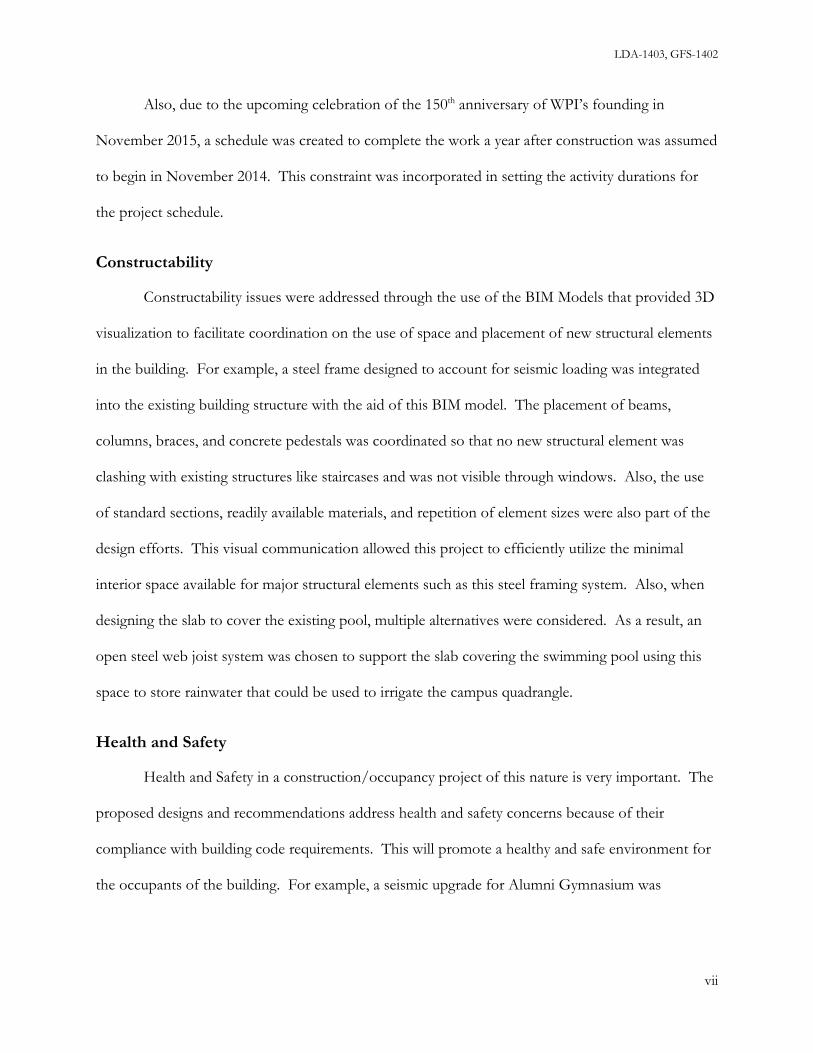
3.3 BIM for the Existing Conditions ........................................................................................................................ 26
3.4 Existing Conditions Analysis ............................................................................................................................... 27
3.5 Results of Existing Conditions Analysis ............................................................................................................ 30
i

LDA-1403, GFS-1402
3.5.1 Roof Framing .................................................................................................................................................. 31
3.5.2 Level 5 & 4 Framing ...................................................................................................................................... 33
3.5.3 Level 3 & 2 Framing ...................................................................................................................................... 34
3.6 Lateral Loads (Wind & Seismic) .......................................................................................................................... 36
3.6.1 Wind Analysis ................................................................................................................................................. 37
3.6.2 Seismic Analysis .............................................................................................................................................. 41
4.0 Proposed Structural Design ...................................................................................................................................... 45
4.1 Structural Impact of Proposed Layout and Major Areas of Renovation ...................................................... 45
4.2 Design Methods .......................................................................................................................................................... 46
4.2.1 Design of Lateral Load Resisting System ....................................................................................................... 46
4.2.2 Design of Showcase Atrium ............................................................................................................................. 48
4.2.3 Design of Pool Floor System ............................................................................................................................ 51
4.2.4 Design of Elevator Shaft ................................................................................................................................... 52
4.3 Results of Structural Design ..................................................................................................................................... 53
4.3.1 New Lateral Load Resisting System ................................................................................................................ 53
4.3.2 Lateral Design for Showcase Atrium (Level 3 Diaphragm) ......................................................................... 58
4.3.3 Pool Floor System .............................................................................................................................................. 59
4.3.4 Elevator Shaft ...................................................................................................................................................... 62
5.0 Construction Planning and Cost Estimating .......................................................................................................... 67
5.1 Construction Planning and Cost Estimating Methods .................................................................................... 67
5.1.1 Scheduling ....................................................................................................................................................... 68
5.1.2 Cost Estimating .............................................................................................................................................. 70
5.1.3 BIM as a Tool for Construction Planning ................................................................................................. 71
5.1.4 BIM as a Tool for Cost Estimation ............................................................................................................. 71
5.1.5 BIM as a Tool for Scheduling ...................................................................................................................... 72
5.2 Construction Planning and Cost Estimating Results ....................................................................................... 72
5.2.1 Site Plan and Logistics ................................................................................................................................... 75
5.2.2 Cost Estimates ................................................................................................................................................ 77
5.2.3 Schedule ........................................................................................................................................................... 78
5.2.4 BIM – New Model and 5D integration ...................................................................................................... 83
6.0 Conclusions and Recommendations ....................................................................................................................... 86
6.1 Sequence of Work ...................................................................................................................................................... 86
6.2 Recommendations for Alumni Gymnasium Renovation and Future MQPs ................................................... 89
Bibliography ....................................................................................................................................................................... 92
ii

LDA-1403, GFS-1402
Appendix A – MQP Proposal ...................................................................................................................................... A-1
Appendix B – Meeting with Fred Dimauro ............................................................................................................... B-1
Appendix C – Level 3 Framing Concrete Slab .......................................................................................................... C-1
Appendix D – Level 4 Framing (Timber Beams) ..................................................................................................... D-1
Appendix E- Level 4 Framing (Steel Girders) ........................................................................................................... E-1
Appendix F – Existing Columns .................................................................................................................................. F-1
Appendix G – Wind Analysis ...................................................................................................................................... G-1
Appendix H – Seismic Analysis ................................................................................................................................... H-1
Appendix I – Truss Analysis .......................................................................................................................................... I-1
Appendix J – Steel Frame Design ................................................................................................................................. J-1
Appendix K – Showcase Atrium Design ................................................................................................................... K-1
Appendix L – Elevated Pool Slab Design .................................................................................................................. L-1
Appendix M – Cost Breakdown .................................................................................................................................. M-1
Appendix N – Elevator Shaft Calculations ............................................................................................................... N-1
Appendix O - List of E-Files.......................................................................................................................................... O-1
iii

LDA-1403, GFS-1402
List of Figures
Figure 1 - Original 1915 Level 1 Plan (Sub-Basement Level) - Shows Swimming Pool Dimension .................... 5 Figure 2 - Original 1915 Level 2 Plan (Base. Level) - Rifle Range and Bowling Alley Dimensions...................... 6 Figure 3 - Intended Use and Square Footing for Each Floor ..................................................................................... 8 Figure 4 - (Left) Overhead View of WPI campus (Right) Access between Alumni and Harrington to Quad ... 9 Figure 5 - Exterior View - South Side Alumni ............................................................................................................. 12 Figure 6 - Exterior View - West Side Alumni .............................................................................................................. 12 Figure 7 - Exterior View - West Side Alumni .............................................................................................................. 26 Figure 8 - BIM images of the joints on the truss ......................................................................................................... 28 Figure 9 - Section View of Existing Structural System ............................................................................................... 29 Figure 10 - Original photo of the truss construction .................................................................................................. 31 Figure 11 - 2D drawing of concentrated loads on the truss ...................................................................................... 32 Figure 12 - Typical Bay .................................................................................................................................................... 34 Figure 13 - Reinforced concrete specification .............................................................................................................. 34 Figure 14 - BIM image of the slab system .................................................................................................................... 35 Figure 15 - Definition of Transverse ............................................................................................................................. 37 Figure 16 - Brick pier locations....................................................................................................................................... 37 Figure 17 - ASCE 7-05, Table 1-1 .................................................................................................................................. 38 Figure 18 - Wind Pressures on Alumni Building ......................................................................................................... 38 Figure 19 - Resultant Wind Loads on Transverse Walls ............................................................................................ 39 Figure 20 - Shear and Moment Diagrams ..................................................................................................................... 39 Figure 21 - Check of Flexure in 4-9 Brick Pier Due to Wind .................................................................................... 40 Figure 22 - Seismic Pressures on Alumni Building ..................................................................................................... 41 Figure 23 - Results of Visual Analysis ........................................................................................................................... 42 Figure 24 - Progressive Failure ....................................................................................................................................... 44 Figure 25 - BIM image of the current exterior wall view ........................................................................................... 48 Figure 26 - Existing floor slab to be removed ............................................................................................................. 49 Figure 27 - BIM image of the future Atrium view ...................................................................................................... 49 Figure 28 - Plan view of new shear walls ...................................................................................................................... 50 Figure 29 - Edge of pool, joist bearing point ............................................................................................................... 52 Figure 30 - BIM images of the swimming pool within the existing building .......................................................... 52 Figure 31 -Steel Frame Seismic Loads Screen Image from MECA Seismic ............................................................. 54 Figure 32 - Front Elevation: Final Sizes & Unity Check ............................................................................................ 55 Figure 33 - Front Elevation: BIM View, with Concrete Piers ................................................................................... 56 Figure 34 - Rear Elevation: Final Sizes & Unity Check .............................................................................................. 56 Figure 35 - Rear Elevation: BIM View, with Concrete Piers ..................................................................................... 56 Figure 36 - Left/Right Elevation: Final Sizes & Unity Check ................................................................................... 57 Figure 37 - Left/Right Elevation: BIM View, with Concrete Piers .......................................................................... 57 Figure 38 - BIM image of the Level 3 Framing: New CMU Shear Wall & Angle ................................................. 58 Figure 39 - BIM image of the open web steel joist system ........................................................................................ 61 Figure 40 - 2D drawing of elevator CMU shaft ........................................................................................................... 62 Figure 45 - Scheduling Process ....................................................................................................................................... 69 Figure 46 - Construction Flowchart .............................................................................................................................. 74 Figure 47- Site Plan ........................................................................................................................................................... 75
iv

LDA-1403, GFS-1402
Figure 48 - Demolition of Slab (Left) and Stairs (Right) ............................................................................................ 83 Figure 49 - New Steel Framing System ......................................................................................................................... 84 Figure 50 - Open Steel Web Joists at Pool Level ........................................................................................................ 84 Figure 51 - Earned Value Analysis for April 6th, 2015 .............................................................................................. 85
List of Tables Table 1: Table 1604.11 in MA Amendments ............................................................................................................... 32 Table 2 : Weight of Open Web Joist Systems .............................................................................................................. 61 Table 3: Summary Table of Project Cost ...................................................................................................................... 78 Table 4: Critical Path By Month ..................................................................................................................................... 80 Table 5: Critical Path Activities with WBS and Costs ................................................................................................. 81 Table 6: CSI Timescale wih Costs .................................................................................................................................. 82
v

LDA-1403, GFS -1402
1.0 Introduction
Major renovations of historic buildings have many challenges associated with them such as
assessing current conditions, acquiring documentation, preserving the existing historic elements of
the building, and updating the structure based on the building codes in place. Depending on the
level of documentation available, drawings and construction specifications can be lost, difficult to
find or understand, or may not be extremely helpful for the intended scope of work. There also may
not be enough information available for a structural analysis of the building. Facing this challenge
can be even more difficult when major structural changes must be made if the building does not
comply with the present building codes. Changes have to be made with the best interest of the
community in mind, and preservation techniques must be implemented to safe-keep any architecture
or masonry work that is unique to the building.
This project faced these challenges for the renovation of Alumni Gymnasium at Worcester
Polytechnic Institute. Built in 1915, Alumni Gymnasium has become a historic landmark for the
WPI campus [13]. Due to the recent construction of the Sports and Recreation Center there are
now plans to repurpose the building from recreational use into a project center for students and
faculty. A conceptual design has been completed. This project reviewed the existing structural
conditions of the building and designed a structural system that meets the functional needs and
building seismic code requirements for the new use of the building. Cost estimates and construction
schedules for the structural renovation were also developed. The project used Building Information
Modeling (BIM) tools and techniques to support design and construction planning with
visualization, documentation and quantification of information. Initially, site visits and archival
research provided a foundation for the initial structural analysis of Alumni Gym. At the same time,
these findings were documented by creating a Building Information Modeling of the existing
1

LDA-1403, GFS-1402
structural conditions and gain an understanding of the scope of work to be completed for
demolition and construction. Then, major areas of renovation were targeted for design
development using the results from the structural analysis and the architectural renderings that were
developed for WPI prior to the start of this project. These areas included seismic design for the
overall building, a shear wall system for the proposed Showcase Atrium, an elevated slab over the
existing slab to be used as a Robotics Pit, and an elevator shaft to access all Levels. These renderings
that are represented in this report, show the proposed use of space in Alumni Gym and required
various alternative designs that were considered in order to bring these proposed changes to fruition.
Alongside this step, BIM models were utilized to track these changes and linked to the existing
structure in a 3D model with the associated schedule and cost for the project to produce a 5D
model.
The results of this project could be very useful as a reference for actual renovation of
Alumni Gymnasium and other renovation projects that are of similar significance.
2

LDA-1403, GFS-1402
2.0 Background
Worcester Polytechnic Institute (WPI) has a long standing tradition in the New England area
not only in academics, but in athletics as well. In the early years, WPI did have an athletic program,
but there was a lack of support from the school’s administrators and these athletes did not have an
adequate location to train [5]. The development of WPI’s rich athletic history began with the
completion of Alumni Gymnasium in 1915. This building was the hub of all athletic activity at WPI,
up until the recent completion of the new “Sports and Recreation Center” in 2012 which has
currently left Alumni Gym with no immediate propose. Currently WPI wants to shift this building’s
use to academics by converting it into a Project Center with an estimated budget of $12 million and
a timeframe scheduled to begin sometime in late 2014 depending on funding approvals [5].
2.1 WPI Early Athletics
The first WPI athletic team was the 1870 Baseball Team [11]. It was a scrub outfit and it had
little to no equipment or even clothing. It mostly played high school teams with their only college
opponent being Holy Cross. Although it was not taken seriously until 1885, the next organized
sports team to come about was the WPI Football Team. They began play in the mid-eighteen
seventies with interclass games, though they also had poor equipment and a lack of training space
[11]. These student-athletes did not agree with Principal Thompson at the time, who believed that
“shop work” was adequate exercise. In the spring of 1878, the football and baseball teams decided
to create a make-shift gym in a grove just north of Washburn Shops [11]. Although this grove was
later displaced by the new wing of the shop building, it served as the recreational center of campus
for a number of years. This interest in athletics, aroused by the elementary gymnasium, led to the
development of track and field sports with the first interclass track meet held on the area adjacent to
the Boynton Street Wall in 1879 [11].
3

LDA-1403, GFS-1402
In the spring of 1888, WPI was admitted into the New England Intercollegiate Athletic
Association (NEIAA), which was a major step in the athletic movement [11]. This was the time-
frame where the first recorded inter-college competition was held with WPI taking third place in
track and field competitions. This entrance into the NEIAA allowed for the organization of the
tennis team in 1888 as well.
With the rise of the WPI athletic movement there was the need for a new building. Many
students wanted a gymnasium as this would be the center of “Tech” (the nickname used to describe
WPI students) student activities, both athletic and social [12]. Although school administrators only
accepted the plans to build Alumni Gymnasium because it would also serve as a benefit to the
military program, both students and faculty felt like its construction “would create a civic center of
the Institute that would foster spirit and teach men their obligations towards one another, especially
the essence of team work” [12].
2.1.1 History Alumni Gymnasium
Alumni Gymnasium was the first central gym to be built for the WPI community and was
erected at the same time as Alumni Field in 1915 [5]. This building was placed near the center of
campus and provided a home for the expansion of the WPI athletics program at that time. It was
considered a state-of-the-art facility as it had five-stories; three above ground and two below,
including an underground pool. Interestingly enough, the pool was not completed until 1925, nearly
ten years after the completion of Alumni Gymnasium, because there was a debate about whether an
ice rink should have been built in that area instead of the current pool [5]. For reference purposes in
this report, the sub-basement will be referred to as Level 1, the basement as Level 2, the first floor as
Level 3, the second floor as Level 4, and the third floor as Level 5.
4

LDA-1403, GFS-1402
Although Alumni Gymnasium is considered an outdated facility by today’s standards, when
it was built in 1915 there were many distinctive features that made it an impressive structure for the
20th century [5]. The basement floor, or Level 2, was originally a rifle range and a bowling alley for
student use. This floor also contains a balcony that overlooks the underground pool in the sub-
basement Level where swim practices and meets were held. The first floor includes the main
entrance as well as the locker rooms and offices of the physical education department. The second
floor holds a basketball and two racquetball courts, which are on each side of the stairwells. The top
floor, which is the third floor, features an indoor running track with another balcony overlooking
the basketball court below. This can be seen in Figures 1 and 2 below.
Figure 1 - Original 1915 Level 1 Plan (Sub-Basement Level) - Shows Swimming Pool Dimension
Pump Room
Swimming Pool
5

LDA-1403, GFS-1402
Figure 2 - Original 1915 Level 2 Plan (Base. Level) - Rifle Range and Bowling Alley Dimensions
After over fifty years of Alumni Gymnasium being the main athletic facility, the WPI
community decided it needed to update its facilities again [1]. In 1965, construction of Harrington
Auditorium began. This building was connected to Alumni Gymnasium in order to increase the
convenience for student-athletes and included a new basketball court and seating for spectators.
The purpose of this building was to keep up with the school’s growing athletic program and to
increase the amount of space for physical activity [1]. Continuing with this trend, the locker rooms
were expanded in Harrington and a new fitness center was added in Alumni Gymnasium in the
1980’s which was later equipped with a weight room in 1992 as it acted as the school’s fitness center
[5]. The combination of a recent growth in student body population and the increasing awareness
of WPI’s outdated athletic facilities made it apparent that a new, modern recreational facility would
be required on campus to accommodate the growing needs as well as attract future students. In May
Upper Pool Room
Rifle Range
Bowling Ally
6

LDA-1403, GFS-1402
of 2010, construction of a new, fully-operational, state-of-the-art recreational facility began on
Worcester Polytechnic Institute’s campus [2]. The $53 million building featured a 29,000 square
foot gymnasium, a natatorium containing a 25-meter competition swimming pool, rowing tanks,
squash courts, robotics pits, 11,000 square feet of fitness space, and an additional 5,000 square feet
of multipurpose rooms. The completion of this facility in 2012 made it apparent that Alumni
Gymnasium would no longer be needed as an athletic facility. So began the process by faculty,
administrators, and others to re-purpose Alumni into something more beneficial to the WPI
community. This led to the hiring of an Architectural firm, Goody Clancy, who developed an
architectural program and schematic design. [2].
2.1.2 A Building Reborn
Alumni Gymnasium, a campus landmark since 1915, will be the home of the new
“Innovation and Solution Center” at WPI [10]. According to the brochure proposed to WPI by
Goody Clancy, Alumni Gymnasium will become a “Virtual Sandbox.” It will be converted into a
five-level building where students will be able conceive create, and connect ideas. It will include an
open, interactive “Collaborative Workshop for Student Projects” and eight tech suites with flexible
configurations on Level 4, a robotics laboratory and showcase with an observation deck above on
Level 1, a “Business Development Incubator” and new classrooms and workspace for the
Great Problems Seminars on Level 3, an “Exploration and Discovery Center” with advanced
analytical equipment on Level 2, a “Showcase Atrium” with interactive digital displays highlighting
innovations and achievements by alumni and students also on Level 3, and storage rooms on Level
5. These new rooms and workshops are directed at facilitating idea collaboration and giving
students the best resources to accomplish work and change the world [10]. As shown in Figure 3
below, this program provides the intended uses and square footages for each new room.
7

LDA-1403, GFS-1402
Figure 3 - Intended Use and Square Footing for Each Floor
Clancy, Goody. ""A Dynamic Expression of the WPI Plan"" Worcester Polytechnic Institute, 9 Sept. 2013. Web. 9 Sept. 2013.
The transformation of Alumni Gym will also make connections around the WPI campus
simple [10]. The plan will serve to horizontally connect the Quadrangle and the future West
Promenade (area in front of the campus center) with primary entrances that are handicapped
accessible (shown in Figure 4 below). This connection of the two open spaces will take advantage
of Alumni Gymnasium’s prominent site on the WPI campus by featuring two “front doors” which
will create a strengthened presence along the future West Promenade and maintain its distinction on
the Quadrangle by re-establishing the historic freestanding character of the building [10]. Although
these proposed changes will have a positive impact on WPI campus and make WPI a unique and
8

LDA-1403, GFS-1402
exclusive university, the proposed changes in structural design as well historical renovation will
introduce difficult challenges to overcome.
Figure 4 - (Left) Overhead View of WPI campus (Right) Access between Alumni and Harrington to Quad
Clancy, Goody. ""A Dynamic Expression of the WPI Plan"" Worcester Polytechnic Institute, 9 Sept. 2013. Web. 9 Sept. 2013.
2.1.3 Structural Aspects
The design and construction of Alumni Gymnasium was completed according to the
guidelines of the 1911 Laws and Ordinances of the City of Worcester [3]. During the early 20th century,
design and construction was performed by “rule of thumb” approaches to sizing structural elements
and building codes were a collection of “good practices” [3] Buildings that were three stories tall,
similar to Alumni Gymnasium, were required to have brick walls 16 inches thick for the basement
and anything below, as well as 12-inch thick walls for the first three floors above ground. The floors
as, prescribed in Section 31 of this code, state that when a public assembly is designed, the floor
must support no less than 100 pounds per square foot [3]. By following these code requirements
9

LDA-1403, GFS-1402
and a heavy reliance on engineering judgment and experience for determining maximum loads, many
buildings in this era may have been overbuilt [1].
When looking at Alumni Gymnasium, the exterior walls of the first three floors should have
a wall thickness between 16 and 24 inches [1]. From visual inspection they seem to be over 24
inches, and this is correct as the true dimensions from the drawings are about 30 inches [1]. This
clearly shows that Alumni Gymnasium was “overbuilt” as it has a thicker structural shell than
necessary. Unfortunately, some of its others components such as the heating system, plumbing,
windows, interior walls, lights, and roof are in need of major renovations and must be brought into
compliance with current building codes [5].
2.2 Maintenance of Historic Buildings
Many buildings built in the early 20th century consisted of brickwork, especially in the New
England area, as brickwork was the most weather resistant building material at the time [4]. Not
only was brick easily manufactured, but it was the most sustainable material because it required the
least maintenance. This is why many buildings today that are considered historic are usually stone or
masonry. However, like everything else, over time even brickwork starts to deteriorate.
A building is considered historic if it meets three requirements: age (it is at least 50 years
old), integrity (must retain historic physical appearance and remain unchanged), and significance
(direct association with developments that have or have shaped history) [4]. Renovation approaches
for historic buildings generally fall into one of five categories [4]. First, stabilization: a process
involving methods that reestablish a deteriorated property's structural stability and weather tightness
while sustaining its existing form. Second, preservation: a process involving methods that maintain a
property in its present state. Third, rehabilitation: a process involving repairs and alterations to a
property that adapt it to a contemporary use while preserving its historic fabric and character.
10

LDA-1403, GFS-1402
Fourth, restoration: a process that accurately recovers the appearance of a property at a particular
period of time by removing later additions and/or replacing missing features. Or fifth, renovation: a
generic term used to define all work that is meant to make new again [4]. For Alumni Gym,
categories two and four are the most relevant as they must be met to fully complete this
transformation.
2.2.1 Preservation and Restoration Techniques
Alumni Gymnasium is considered a historic building as it meets all three requirements stated
above. [4] Many buildings of this nature usually have been damaged by structural reasons or water
infiltration. A building of this age has gone through many storms and weather cycles which can
deteriorate building components such as the brick mortar, concrete structures like foundations, and
the materials that comprise the roof. A series of steps must be followed in order to successfully
resolve the problem without damaging or jeopardizing the historic nature of the building as
described in categories two and four above. First, if the mortar is missing or loose, the joints should
be cleaned out and repointed using a mortar mix which closely matches the composition, joint
profile, and color of the original. Second, there must be careful removal of mortar from the joints so
as not to damage the brick edges. Third, whenever partial or total foundation replacement is
required, the new foundation walls should be faced in materials that match the original in
appearance. Fourth, whenever replacement brick or stone is needed, there must be a use of a
material that closely matches the original in size, color, and texture. Fifth, whenever masonry has
been painted, it must be repainted after removing all loose paint. Sixth, any cleaning should be done
with the gentlest method possible and should be stopped at the first evidence of damage to masonry
[4]. These preservation steps must be taken when restoring the masonry on Alumni Gym as shown
below in Figures 5 and 6. These pictures show the structural shell of Alumni Gym and highlight
some of the elements of its historic stonework that will need refurbishing. These items are
11

LDA-1403, GFS-1402
important to keep in mind as they give Alumni its historic appeal and the campus a historic
atmosphere.
Figure 5 - Exterior View - South Side Alumni
Figure 6 - Exterior View - West Side Alumni
12

LDA-1403, GFS-1402
The above methods are crucial and specific to maintaining the masonry of an historic
building. There are also fundamental concepts that relate to all aspects of historic buildings and in
particular to Alumni Gymnasium. First, every reasonable effort should be made to provide a
compatible use for a property that requires a minimal alteration of the building, especially when the
work has to be approved by the Worcester Historic Commission [6]. Second, the distinguishable original
qualities or character of a building should not be destroyed, such as the removal or alteration of any
historic material or architectural features. Third, all buildings, structures, and sites should be
recognized as products of their own time, as in, alterations which have no historical basis and which
seek to create an earlier appearance are not necessary. Fourth, changes that may have taken place in
the course of time are evidence of the history and development of a building and should be
recognized and respected. Fifth, examples of skilled craftsmanship that characterize a building
should be treated with sensitivity. Sixth, deteriorated architectural features should be repaired rather
than replaced, wherever possible. However, if a replacement is necessary, the new material should
match the material being replaced in composition, design, color, texture, and other visual qualities.
Seventh, the surface cleaning of structures should be undertaken with the gentlest means possible.
Eighth, contemporary design for additions to existing structures or landscaping shall not be
discouraged. Ninth, wherever possible, new additions or alterations to structures shall be done in
such a manner that, if they were to be removed in the future, the essential shape of the original
structure would remain the same [4]. These nine concepts listed above address higher level than just
masonry restoration. They represent the merging of the past to the present which is a highly
sensitive process.
13

LDA-1403, GFS-1402
2.2.2 Worcester Historic Commission
One group whose objective is maintaining the integrity of historic buildings in Worcester,
MA, is the Worcester Historic Commission [6]. The function of this association is to issue certificates of
appropriateness, certificates of non-applicability, and certificates of hardship to any construction
project or alteration of any historic building. They conduct research about places of historical
interest and advise the Planning Board, the Worcester Redevelopment Authority, the Executive
Office of Economic Development, and certain national agencies such as the National Park Service
and the National Trust for Historic Preservation on all questions involving historic sites. Most
importantly, the commission can cause a major delay to any project or alteration involving a historic
building regardless if the building has a designated status or not. The Commission can give
recommendations to owners of historic buildings in Worcester on issues of preservation and
determine what can and cannot be done to the building in order to preserve its historic significance.
If the owner does not agree upon receiving these suggestions or the given proposal, the
Commission, through the City of Worcester, can delay the beginning of construction for up to one
year [6]. Most owners that are faced with this dilemma usually just wait out the delay and then start
construction as intended; however, this has a seemingly large effect not only on the planning
modifications to the building itself, but on the political perspective as well [6]. Currently, the only
portions of Alumni Gym that have to be “kept original” are those parts of the building that can be
viewed from a public street, especially the windows. As Alumni Gym’s entire North side is visible
from Institute Road, these areas would have to be historically preserved.
2.3 How to Analyze an Existing Structure
According to International Existing Building Code (IEBC) 2009 Edition, the project scope
determines which code provisions the building must comply with. Due to the degree of scope
14

LDA-1403, GFS-1402
presented so far for renovations to Alumni Gym, it was determined that this project should be
classified as a level 3 renovation. A level 3 renovation means that all building systems in Alumni
Gym must be analyzed and comply with current building code specifications. Each existing
structural system is analyzed to verify compliance with the current codes.
2.4 Structural Evaluation of Buildings
In a building renovation project of this magnitude, and in particular when dealing with a 100
years old facility, an evaluation of the structure is a primary consideration in order to determine the
adequacy and suitability and code compliance of the structural systems in place. The major
structural systems that are investigated include all existing foundations, floors, columns, and the roof
system.
2.4.1 Structural Building Systems
Foundations are the bottom most part of a building’s structure; they are placed below grade
in order to transfer loads from the upper structure or superstructure into the soil. The primary
consideration during design of foundations is to limit differential settlement of the structure. This is
to ensure that the above structure is not altered or disturbed by the foundation settling at different
elevations. Some ways to limit settlement are to verify adequate soil capacity and to spread the load
out over a sufficient area to minimize bearing pressure. Foundations are primarily comprised of
strip footings or piers. Footings can either be considered deep footings, or shallow spread footings.
The piers can either be founded on deep soil or supported by piles (in this case the pier is a pile cap).
The option on which type of footing to use is dependent on the type of soil conditions present at
the site. Deep footings can be either wooden piles, steel piles, or pressure injected concrete footings
(pifs). Shallow spread footings are usually made from reinforced concrete. Foundation walls sit on
footings and are primarily constructed with reinforced concrete, stones, or bricks as they must be
15

LDA-1403, GFS-1402
designed adequately to resist the gravity loads imposed on it from the above structure and lateral
earth pressures.
Floors and walls are horizontal and vertical members, respectively, of buildings that serve a
variety of purposes. Other than the obvious purpose of an area for people to walk on or providing
shelter from the outside conditions, floors and walls serve to resist both gravity and lateral loads.
The gravity loads floors and bearing walls must carry are both dead and live loads. The dead and
live loads are determined by a floor’s intended uses, which are spelled out in building codes. Floors
and non-load bearing walls are supported by beams and columns, which transfer loads down the
structure, and eventually make their way into the foundation and soil. Floors and walls also act
together to resist lateral loads due to wind and seismic by acting as a system of horizontal and
vertical diaphragms. Walls that resist these lateral forces are known as shear walls. In addition to
shear walls, beams and columns, constructed as a moment frame can resist against lateral loads.
This involves moment connections between beams and columns, and tying the floor into these
members.
The roof covers the top of a structure. Generally, the roof must be designed to carry dead
and snow loads, which are again determined by the building codes. In addition to gravity loads, the
roof serves as a diaphragm to gather lateral loads due to wind and seismic forces and transfer these
lateral loads to the resisting shear walls or moment frames. The roof can be constructed from steel,
wood, concrete, or any other suitable material and most systems are built as trusses, or a beam/
column assembly.
Understanding the structural system of Alumni Gymnasium served as a basis for the work to
be performed. Since this is a renovation project to an existing building, the structural system in
place must be understood first before any alterations are made.
16

LDA-1403, GFS-1402
2.4.2 Building Codes
For non-residential and residential structures above 2 families, the following codes and
standards govern building construction in Massachusetts:
1. International Building Code (IBC) 2009 Edition
2. MA Amendments to IBC-2009
3. Minimum Design Loads for Buildings and Other Structures by the American
Society of Civil Engineers (ASCE 7) 2005 Edition
4. International Existing Building Code (IEBC) 2009 Edition
Since the Alumni Gym is an existing building the construction is only controlled by either
Chapter 34 of the IBC or the separate IEBC Code. In Massachusetts, one of the MA Amendments of
the IBC is to delete Chapter 34 and adopt the IEBC in its entirety. In addition to the above codes,
the following material specifications are adopted by reference in the IBC and control the design of
structural members:
1. Concrete - Building Codes Requirements for Structural Concrete (ACI 318-11) by the
American Concrete Institute
2. Masonry - Building Code Requirements and Specification for Masonry Structures (TMS
402/ACI 530/ASCE 6) by the following 3 societies:
The Masonry Society (TMS 402)
American Concrete Institute (ACI 530)
American Society of Civil Engineers (ASCE 6)
3. Structural Steel - Specification for Structural Steel Buildings (ANSI/AISC 360) by:
17

LDA-1403, GFS-1402
American National Standards Institute
American Institute of Steel Construction
4. Wood - National Design Specification for Wood Construction (NDS) by:
American Forest & Paper Association
American Wood Council
The above codes and regulations provide the guidelines for which to analyze and create new
designs for Alumni Gym. The IBC 2009 and ASCE 7-05 provide guidelines for the determination
of load cases that are to be applied to the existing and new portions of the structure. The individual
material codes provide analysis and design values for different material properties. The two codes
will be used together to guide the design process and solve the various concerns that arise.
2.5 Building Information Modeling
In recent years, great investment has gone into the use of Building Information Modeling
(BIM) as a tool for design and construction. BIM is an intelligent model-based process that
provides insight through enhanced visualization and promotes integrated solutions for buildings and
infrastructure projects. Through the use of BIM technologies, multiple disciplines can come together
and collaborate to produce a central model. This model is a 3-Dimensional representation of the
project that may incorporate other facets like cost, schedule, or energy analyses. This process allows
businesses to build projects faster, more economically, and environmentally conscious [9]. BIM
allows contractors of all trades to create a 3D model of their work that can later be compiled into
one realistic building model. From there, any detection of clashes (when more than one element is in
the same space) is found and resolved before construction begins. This process prevents the waste
of extra time and money if a mistake was to be made on it, especially in the current economy. Using
18

LDA-1403, GFS-1402
BIM technologies assists in eliminating these mistakes and increases profitability and productivity of
the building. Almost half (46%) of the infrastructure organizations, surveyed by Autodesk, are
currently using BIM technologies and processes on some part of their infrastructure portfolio; a
recent growth from only 27% two years ago. The vast majority (89%) of these companies that
currently use BIM for infrastructure report that it is extremely beneficial in keeping a project on time
and on budget [9]. They also experience benefits that impact their internal business functions as
well.
2.5.1 BIM’s Importance in Design
BIM has many key benefits during the design phase of a project. Project scope, schedule,
and cost all must be managed well during the design phase as this is the phase where many changes
are made to these variables. Through traditional methods, if changes to the variables mentioned are
made later in the project, delays can occur and great effort has to be made to upkeep the project.
This can cause delays with increased costs negatively affecting relationships between consultants and
clients. With BIM these changes to the digital model can be better coordinated, eliminating the
possibility of many costly delays [9].
If a client were to decide to change the scope of their project, BIM can conveniently provide
the tools necessary to make the changes. When one design value is changed, further calculations to
other structural elements do not need to be made as BIM will automatically update the changes
throughout the project. This allows the design team effective and speedy delivery of documents and
visual elements. With the implementation of the 3D model and the architectural conceptual design
provided by Goody Clancy, an architectural firm hired by WPI, future planning and construction
can be evaluated more efficiently by the WPI Department of Facilities instead of only having 2D
blueprints to rely on.
19

LDA-1403, GFS-1402
2.5.2 BIM’s Importance in Construction
Another useful feature in BIM is the 5D capability that provides available information on
building quality, schedule, and cost [9]. Cost estimating and value engineering can be accelerated
especially when updates are made to any plans or estimates. Also, site plans can be prepared and
used for communication to minimize the impact of construction operations on the owner. Due to a
higher quality of documentation and better construction planning through BIM, administrative and
overhead costs can be reduced [9]. Cost estimates and schedules must be developed and then linked
to the 3D model to develop the 5D in software like Navisworks. The estimates and construction
planning would reflect the structural changes proposed as well as the construction methods and site
planning necessary to design and plan for this renovation. Altogether, the 5D model can represent
the costs of the project from each individual phase throughout the scope.
With Alumni Gymnasium being a renovation project, there are many variables, some of
which may not be clear initially, and having the ability to make timely and consistent updates to costs
and planning is crucial. Additionally, with the building located in the center of campus, proper
planning must be executed so as to not interfere with the campus and the student life.
2.6 LEED Certification
Leadership in Energy & Environmental Design is an innovative measure that is being
utilized in the construction and renovation of many building environments. The focus of LEED is
to provide building owners and operators the opportunity to implement green design, construction,
operations, and maintenance techniques into their specific project [7]. Through these measures,
owners can reduce waste, conserve energy, and improve the environmental quality of a building.
This can be achieved in a multitude of ways and is applicable to various types of projects:
20

LDA-1403, GFS-1402
• New Construction & Major Renovation • Core & Shell • Schools • Retail: New Construction & Major Renovations / Retail: Commercial Interiors • Healthcare • Commercial Interiors • Existing Buildings: Operations & Maintenance • Homes • Neighborhood Development [7]
In order to achieve LEED certification, a building goes through a rating system that verifies
it has been designed and built using strategies such as sustainable site development, water savings,
energy efficiency, materials selection, and indoor environmental quality. There are four levels of
LEED certification a building can achieve that depend on the number of points it accrues. The
system is a 100-point system plus six points for Innovation and Design and four points for Regional
Priority. Buildings receive a higher level of certification depending on how efficiently LEED
principles are incorporated into the design and construction of the building [8].
These levels include:
2.6.1 How to Gain LEED Points
There are five main categories in which a building can earn points in order to reach
certification. The number of points that are earned in each category determines the level of
21

LDA-1403, GFS-1402
certification that the building achieves. Within each credit category, there are prerequisites that must
be satisfied to earn points:
• Sustainable site credits
• Water efficiency credits
• Energy & atmosphere credits
• Materials & resources credits
• Indoor environmental quality
Generally, these categories aim to promote proper site development to reduce the impact on
the surrounding ecosystem, smarter use of resources like water consumption, more innovative
energy strategies in the building, sustainable building materials and recycling waste, and better indoor
air quality and access to daylight and views [8]. There are also bonus categories that address
innovation in design and operations as well as regional priority credits depending on the
geographical location of the building and the environmental priorities of the region. Since Alumni
Gymnasium is a very old building, many of these strategies are not in place but can be achieved
successfully by observing the systems that are already in place and developing strategies to improve
them. The aim was not to create a full LEED study on Alumni Gymnasium but instead to
recommend alternatives in design and construction methods that would earn LEED points. Alumni
Gymnasium fell under LEED for New Construction and Major Renovation since major work would
be done to the structure. Using this guideline, the team was able to recommend ways to earn these
points not only to become LEED certified but to promote more sustainable practices in
construction. The reason for the incorporation of LEED was due to the precedent that WPI has set
in the construction of other buildings on campus. These include East Hall, Faraday Hall, and the
Sports and Recreation Center to name a few. This gives WPI a preliminary look into the LEED
options available for Alumni Gymnasium.
22

LDA-1403, GFS-1402
2.6.2 Benefits of LEED to Alumni Gymnasium
Due to the age of Alumni Gymnasium and the design and construction methods used at that
time (circa 1910), the structural and mechanical systems of this building are very outdated. Bringing
the infrastructure up to code is one of the most important progressions in the renovation process.
Since there are many systems that comprise the building that need to updated, using LEED as a
guideline will not only bring the building up to code but also make it an efficient and
environmentally friendly system. For example the mechanical and electrical systems are out of date
and replacing those systems with new technology will reduce waste, and operations and maintenance
costs. Also, renovating the structural portions of the building will prove effective in terms of
insulating the building, saving energy, and reducing maintenance costs of the outdated systems as
well as provide a healthier, more pleasing environment. One such challenge will be determining the
proper materials and methods when renovating the basketball court on the top floor. It is a very
open space with thermally inefficient windows and an outdated heating system that has to be run
around the clock to maintain a comfortable temperature [1]. Another area for LEED consideration
is the elevated slab to cover the existing pool area. There is discussion to use the volume under the
slab to store rainwater to use to irrigate the quad in turn reducing municipal water use. Finding
alternatives will be very helpful in improving these areas and the other sections of the building while
preserving the historic façade on the exterior. Applying LEED strategies in Alumni will also follow
the precedent set by other buildings on the WPI campus like East Hall, the Sports and Recreation
Center, and Faraday Dormitory. However, because this is a renovation project and not new
construction, the application of LEED alternatives must be incorporated efficiently in the design
and construction with the constraints of cost and time. This project does not incorporate LEED
into all design solutions but instead recommends areas where LEED can be integrated.
23

LDA-1403, GFS-1402
3.0 Assessment of Existing Building Conditions
In order to gain an understanding of the extent of this renovation, an assessment of the
existing building conditions was conducted. First, background information was gathered on the
overall building through archival research. Next, field investigations provided information regarding
the existing structural elements that comprise Alumni Gymnasium. These finding were documented
in a Building Information Model providing visualization and accurate details for dimensions of the
overall building as well as the interior structure. Finally, a structural investigation of these elements
was performed with seismic consideration to identify the structural components that met building
code requirements and the ones that did not.
3.1 Gathering Information
Developing a 3D model of the existing conditions in Alumni Gym involved an information
gathering process that was specific to the building. This information was gained from all available
drawings of the building, and inspections of the site, where photographs were taken. Site visits were
used to verify conditions stated on drawings, and to acquire any additional information required to
analyze the building. Seventeen sheets of the original building drawings were obtained from the
“WPI Archive and Special Collection Department” in the WPI Gordon Library. These drawings
were the work of Hewitt & Brown Architects and Engineers, and they were dated 1914. It is to be
noted that on the available drawings, there are several references to additional drawings sheets that
were part of the original set, but are no longer available for unknown reasons. Another set of
drawings developed by EYP Architects was given to the group from the WPI Department of
Facilities. Further research conducted at the “WPI Archive and Special Collection Department”
included obtaining the original construction specifications from 1911, photographs from the actual
construction process from 1914-1915, and information from publications of the time.
24

LDA-1403, GFS-1402
3.2 Field Investigations
With the aid of existing drawings of Alumni Gym, the structural investigation commenced
and investigation of the existing conditions began. First, the location, size, spacing, and material
type of all structural systems and their members were documented. The structural systems
examined included roof framing, floor framing, exterior bearing wall construction, and foundations.
The roof framing was a truss system that was supported by the exterior brick walls. To
understand the roof framing, the roof truss individual members, connections, and spacing that
comprise the trusses were measured. In addition, the purlins and deck spans and sizes that span
across the truss were noted as well. A laser level was used to determine the joints and their spacing
within a typical truss. The laser level was placed on Level 4 (gym floor) and shot up to the joint. A
location was marked by tape on the gym floor, and measurements were taken from mark to mark.
From this, the truss geometry was determined.
The floor framing was determined by locating and sizing all columns, beams and joists, as
well as the holes that existed in the floor. Investigations indicated that Level 4 and 5 framing
consists of steel girders and timber beams spanning girder to girder. The species of the timber
beams were found from the original construction specifications and along with ASCE 7-05 the
design values of the beam, based on the species of wood, were determined. The girder and column
section properties were field measured. Level 3 consists of a concrete slab, supported by concrete
beams and columns. The floor slabs on Levels 2 and 1 each bear on grade. Next, the thickness of
the exterior brick bearing walls was measured at a window opening at each floor. Finally, to the
extent possible, investigations into the size of the foundation walls and footings were completed.
25
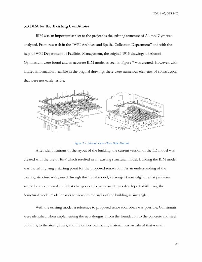
LDA-1403, GFS-1402
3.3 BIM for the Existing Conditions
BIM was an important aspect to the project as the existing structure of Alumni Gym was
analyzed. From research in the “WPI Archives and Special Collection Department” and with the
help of WPI Department of Facilities Management, the original 1915 drawings of Alumni
Gymnasium were found and an accurate BIM model as seen in Figure 7 was created. However, with
limited information available in the original drawings there were numerous elements of construction
that were not easily visible.
Figure 7 - Exterior View - West Side Alumni
After identifications of the layout of the building, the current version of the 3D model was
created with the use of Revit which resulted in an existing structural model. Building the BIM model
was useful in giving a starting point for the proposed renovation. As an understanding of the
existing structure was gained through this visual model, a stronger knowledge of what problems
would be encountered and what changes needed to be made was developed. With Revit, the
Structural model made it easier to view desired areas of the building at any angle.
With the existing model, a reference to proposed renovation ideas was possible. Constraints
were identified when implementing the new designs. From the foundation to the concrete and steel
columns, to the steel girders, and the timber beams, any material was visualized that was an
26

LDA-1403, GFS-1402
obstruction to the proposed layout. The model view of the structural system showed what elements
were in the way and what upgrades were needed in specific areas.
Through the use of BIM, the project was driven by the 3D model that made it easier to
adjust proposed ideas for renovation. Materials of the building that would have to be removed due
to interference of the new construction were identified. Along with demolition, the new design was
phased with the construction schedule.
3.4 Existing Conditions Analysis
It was essential to document the existing conditions of Alumni in a 3D BIM model to gain
an understanding of the structure in place. The 3D model was later used for coordination during
design and construction. Additionally 2D drawings were extracted from the 3D model for use
during analysis and presentation. After this documentation was completed, an analysis of all
structural members and systems was conducted. The analysis identified all structurally deficient
areas in Alumni Gym. This provided an understanding of the areas that needed to be further
explored, and that needed designs developed as solutions.
The analyses of the structural systems in Alumni Gym were divided into two main groups,
gravity loads (vertical forces) and lateral loads (horizontal forces). The types of gravity loads that
Alumni Gym was determined to be exposed to were snow, dead, and live. The lateral loads that
Alumni Gym was determined to be exposed to were wind and seismic. Also, judgment was
important for identifying other loads or for the need to use higher values than in ASCE 7 that had
to be used based on design requirements.
At Alumni Gym, the gravity load resisting building components were roof (purlins and
trusses), floors (walls, girders, beams, and columns), and foundations (footings and foundation
walls). The snow load and dead loads (of the roof system) are applied to the roof as a pressure
27

LDA-1403, GFS-1402
(lbs/ft2) and dispersed across the roof diaphragm. The loads then are distributed as loads per lineal
foot (lbs/ft) along the purlins. The purlins act as simply supported beams connected to the top
chord of the truss (at the joints of the truss, see Figure 8).
Figure 8 - BIM images of the joints on the truss
The reactions at the end of the roof beams act as point loads on the truss. The point loads travel
through the truss members (top chord, bottom chord, and webs) to the end support reactions,
bearing on the 1’-9” thick brick wall.
28

LDA-1403, GFS-1402
Figure 9 - Section View of Existing Structural System
In terms of the loading pattern on each floor, Figure 9 above displays the existing structural
components and their relationship to each other as explained further. Each floor in Alumni Gym
has a dead and live load. The dead load applied to the floor was comprised of the weights of the
resisting structural members and any appreciable permanent loads (such as mechanical equipment,
partition, etc.). The live load applied to the floor was specified from building codes depending on
29

LDA-1403, GFS-1402
usage. A certain combination of these loads is applied to the floor diaphragm as a pressure (lbs/ft2).
For the framing for Levels 5, and 4, the floor diaphragm transfers the loads to the timber beams.
The timber beams are supported at each end by a steel girder, which span column to column (or
column to brick bearing wall). For Level 3 framing, and a portion of Level 2 framing, the load path
is similar, although a concrete slab, beam, and column system is in use. There are 4 main column
lines in the building that all align from floor to floor. The bottom most columns are supported by
concrete spread footings that disperse the loads to the soil. The brick bearing walls are supported at
their base by a concrete strip footing.
The lateral force resisting system utilizes similar building components to the gravity resisting
systems; however, the load direction and resultant stresses are different. Wind blows on the
building, and can come from any direction. Consider wind hitting the front exterior wall. The wind
exerts a pressure (lbs/ft2) across the entire wall area. This pressure is gathered by the floor
diaphragm, which then brings the load into the exterior walls, located in the direction perpendicular
to the front exterior wall. Seismic loads can be analyzed as a dynamic load, or an equivalent static
load can be applied across each diaphragm of the building. The diaphragm and resisting walls then
resist the seismic loads in the same manner as the wind loads.
3.5 Results of Existing Conditions Analysis
To fully understand the structural capacity of Alumni Gym, the structural shell was analyzed
using information from the International Existing Building Code (2009). The areas that were analyzed
for gravity load compliance were the framing for the roof, Level 5, Level 4, Level 3, and Level 2. In
addition, the building’s lateral resisting system was checked against the wind and seismic
requirements. The following summarizes the group’s findings, and highlights the insufficient areas.
30

LDA-1403, GFS-1402
3.5.1 Roof Framing
The roof is framed by a series of trusses spaced 24’-7”. Each truss is constructed with steel
angles, long legs back to back. The roof has purlins (15” I shape) that span truss to truss. There is
also an upper portion of the roof, known as a monitor, that is 5 feet higher than the truss ridge,
framed with I shapes. Figure 10 below shows the truss and monitor during actual construction.
Figure 10 - Original photo of the truss construction
Once the framing of the roof was determined, the geometry could be analyzed for code compliance,
using a roof snow and dead load combination from ASCE7-05 and IBC 2009. The roof snow load
was determined through values and equations from the IBC 2009, and the MA Amendments to IBC
2009. The ground snow for Worcester, MA was found to be 55 lbs/ft2 from Table 1604.11 in the
MA Amendments; see Table 1. Through conversion factors from ASCE 7-05, the ground snow was
converted into a roof snow load P = 39 lbs/ft2.
31

LDA-1403, GFS-1402
Table 1: Table 1604.11 in MA Amendments
Next, the roof dead load was determined to be 15 lbs/ft2, which included the weight of the slate
roofing, roof deck, monitor, and mechanical equipment. These loads were then resolved from the
diaphragm, onto the purlins according to their spacing, and then as point loads on each truss; see
Figure 11.
Figure 11 - 2D drawing of concentrated loads on the truss
The stresses in the top, bottom, and web of the truss were computed using the analysis
software Visual Analysis. Each member’s demand was then compared to its capacity. The bottom
and top chord are built with LL8x6x3/4. The maximum stress in the top chord was only 40% of
32

LDA-1403, GFS-1402
capacity, and the max stress in the bottom chord was only 28%. These capacities were based on
Allowable Stress Design (ASD). The most critical web was an LL4x4x3/4 and the maximum stress
was about 10% of capacity. Overall, the trusses were adequate, and met the current IBC 2009 code
for gravity load capacity.
3.5.2 Level 5 & 4 Framing
The Levels 5 & 4 are framed by steel girders and wood timbers, with wood deck, supported
by pipe columns that sit on the concrete columns below. Through field measurements, it was
determined that the wood deck was 3” tongue and groove. The wood timbers were full 12”x12”.
The steel girders that support the timbers were either an 18”I, in 3 bays, or a 24”I in the widest bay.
The 3” wood deck had a maximum span of 7 feet, from timber to timber. The timbers had a
maximum span of 16’, from girder to girder. The 18” I girder had a maximum span of 28’, and the
24”I had a maximum span of 34’. A typical bay is displayed in Figure 12 below. Using this
information a gravity load analysis was performed on these elements and found that each element
met the IBC (2009) standards according to Load and Resistance Factor Design (LRFD) provisions.
The floor was computed to have a dead load 18lbs/ft2 and a live load capacity of 135 lbs/ft2. The
code requires a design live load 100 lbs/ft2 for spaces designated for use as a mechanical/storage
area (Level 5), and assembly area (Level 4).
33

LDA-1403, GFS-1402
Figure 12 - Typical Bay
3.5.3 Level 3 & 2 Framing
Level 3 and the west half of Level 2 are framed by a monolithic reinforced concrete slab
supported by concrete beams and columns, which sit on spread footings, see Figure 13. The slab is
a one-way slab system spanning beam to beam. The original construction specifications for Alumni
Gym specify that all concrete floors and stairs were designed to carry a live load of 100 lbs/ft2, in
addition to self-weight and dead loads; an excerpt from the original specifications can be seen below.
Figure 13 - Reinforced concrete specification
34

LDA-1403, GFS-1402
To be able to determine the exact capacity of the floor and its supports, the reinforcing steel
size and spacing must be known. The original building plans that were obtained for this project do
not indicate the required reinforcement information, and the only other way to determine this would
be to drill inspection holes in each member to locate the reinforcing. This method was highly
impractical for this project, so an exact analysis of the beams and columns could not be done. Also,
there are not techniques for imaging the embedded steel. However, an approximate analysis of the
slab was done to determine the minimum reinforcing steel requirement. With a dead load of 150
lbs/ft2 and an assumed live load of 100 lbs/ft2, the minimum steel required was found to be .64
in2/ft. This would call for 4 #4 bars at 3 in. spacing for a 12 inch strip of slab. This steel
reinforcing can reasonably be assumed to have been used at the time of construction. An exact
analysis for the beams and columns could not be performed without knowledge of the exact steel
reinforcing and intended method of design such as continuously supported or simply supported.
Level 3 framing was found to have met, if not exceed the live load specified for the proposed new
usage from IBC 2009, Table 1607.1. An image of the slab framing from the BIM model is shown in
Figure 14.
Figure 14 - BIM image of the slab system
35

LDA-1403, GFS-1402
3.6 Lateral Loads (Wind & Seismic)
In review of the proposed work and the International Existing Building Code 2009 (IEBC), the
complete renovation of the building assigns the building into the category of Chapter 8, Alterations-
Level 3. Further, the removal of a substantial part of the Level 3 diaphragm (approximately 12% of
the total floor area) requires evaluation of the building for current wind and seismic loads.
The wind and seismic loads on the building were determined in accordance with IBC 2009
(ASCE 7-05). The maximum stresses occur within the transverse walls (see Figure 15 for definition
of transverse). This is due to the rectangular shape of the building: there is more area at the front
and rear elevations to take load, and shorter walls in the perpendicular direction. The loads in the
longitudinal direction are 70% (90ft/130ft) of those in the transverse direction. The walls in the
longitudinal direction are 44% longer than the walls in the transverse direction. Consequently
further analysis of the longitudinal walls was not warranted at the time. The local brick pier stresses
(see Figure 16 for brick pier locations) were calculated and compared to allowable values for
unreinforced brick masonry. In addition, the overall building stability was checked. The wind loads
in the longitudinal direction were not considered as the longitudinal walls resist winds on the left and
right sides.
This Space Has Been Intentionally Left Blank
36

LDA-1403, GFS-1402
Figure 15 - Definition of Transverse
Figure 16 - Brick pier locations
3.6.1 Wind Analysis
The wind pressures on Alumni Gym were determined from the software program MECA
Wind, in accordance with ASCE 7-05. The input for Worcester’s basic wind speed was found to be
100 mph, from Table 1604.11 in the MA Amendments. The importance factor I, was determined
from ASCE 7-05, Table 1-1, to be category III as shown in Figure 17. The figure below is an
excerpt from ASCE 7-05, Table 1-1 that describes the nature of occupancy, for Category III:
37

LDA-1403, GFS-1402
Figure 17 - ASCE 7-05, Table 1-1
The building footprint, floor heights, and ridge height were entered and MECA Wind computed the
following pressures shown in Figure 18. Consistent with the provisions of ACSE 7-05, there are
different pressures for the roof and walls, and the pressures intensify at the corners.
Figure 18 - Wind Pressures on Alumni Building
The computed wind pressures were then resolved across each diaphragm level, and the shear and
moment values at each Level were computed which can be seen in Figure 19 and 20 below. Note
38

LDA-1403, GFS-1402
that Level 5 is not considered a continuous diaphragm because it is a suspended track, with a large
hole in the middle.
Figure 19 - Resultant Wind Loads on Transverse Walls
Figure 20 - Shear and Moment Diagrams
39
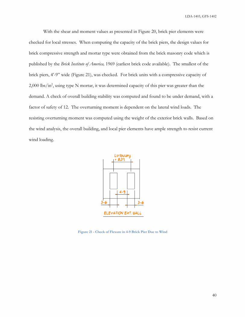
LDA-1403, GFS-1402
With the shear and moment values as presented in Figure 20, brick pier elements were
checked for local stresses. When computing the capacity of the brick piers, the design values for
brick compressive strength and mortar type were obtained from the brick masonry code which is
published by the Brick Institute of America, 1969 (earliest brick code available). The smallest of the
brick piers, 4’-9” wide (Figure 21), was checked. For brick units with a compressive capacity of
2,000 lbs/in2, using type N mortar, it was determined capacity of this pier was greater than the
demand. A check of overall building stability was computed and found to be under demand, with a
factor of safety of 12. The overturning moment is dependent on the lateral wind loads. The
resisting overturning moment was computed using the weight of the exterior brick walls. Based on
the wind analysis, the overall building, and local pier elements have ample strength to resist current
wind loading.
Figure 21 - Check of Flexure in 4-9 Brick Pier Due to Wind
40

LDA-1403, GFS-1402
3.6.2 Seismic Analysis
Seismic loads according to ASCE 7-05 were calculated, and investigated with MECA Seismic.
The building lateral resisting system was classified as a “bearing wall system.” The “response
modification coefficient R” was input as 1.5, for unreinforced masonry walls. The base shear and
moment are given in Figure 22 below, as well as the moment and shear values at each diaphragm
Level.
Figure 22 - Seismic Pressures on Alumni Building
Using the values obtained from MECA Seismic, the end brick wall was then modeled in the finite
element analysis software, Visual Analysis. The height and width were input, and 1’x1’ plate elements
were defined across the entire wall. Plates were then deleted to model window openings, and
sloping wall segments. The results of the analysis can be seen below in Figure 23. The most critical
brick stresses occur at the right and left end of the wall at Level 3 framing. This critical area is
41

LDA-1403, GFS-1402
shown in blue below, and has a magnitude of 337 lbs/in2 in tension. The allowable stress for a brick
unit with a compressive capacity of 2,000 lbs/in2, using type N mortar is 19 psi, meaning that the
brick piers are highly overstressed due to the seismic loads. When considering building overturning
due to seismic loads, the factor of safety is only 2.7. The overturning moment is dependent on the
lateral seismic loads. The resisting overturning moment was computed using the weight of the
exterior brick walls.
Figure 23 - Results of Visual Analysis
In a case of an earthquake, the consequences of failure in the brick walls could be
catastrophic. The brick walls serve as a point of bearing support for the framing at each Level and
the roof trusses. Once one pier has been overstressed and compromised, the stress values increase
42

LDA-1403, GFS-1402
for the adjacent piers, and the effect continues. Failure of the brick walls will cause progressive
failure in the floor and roof framing system, which is not a desirable failure mode. In fact, modern
code provisions contain explicit information that requires sufficient redundancy in construction to
prevent failures by progressive collapse. The seismic analysis revealed a structural deficiency in the
seismic lateral resisting system for Alumni, and a new more robust and ductile system was
implemented.
One may think the structural shell of Alumni Gym is so strong that it can withstand anything
because of the fact it has stood for 100 years. The fact is when an archaic, non-ductile system is
analyzed against current building standards, it does not pass. There is a reason why unreinforced
masonry construction, as a means for lateral resistance, is not permitted in modern cases. Figure 24
below illustrates the development of a progressive failure and how the magnitude of stresses
becomes increased once one pier element fails. The figure shows the new stresses across the entire
wall are all over 400 lbs/in2, well above capacity, and the max stresses are upwards of 1,000 lbs/in2.
This Space Has Been Intentionally Left Blank
43

LDA-1403, GFS-1402
Figure 24 - Progressive Failure
This Space Has Been Intentionally Left Blank
44

LDA-1403, GFS-1402
4.0 Proposed Structural Design
After extensive analysis of the existing structure and determination of the major areas of
renovation, structural designs were developed to fit the needs of the newly configured building and
to enhance the structural stability of the completed facility. The methods of the new structural
design will be presented first in section 4.2, followed by the results and summarized calculations in
section 4.3.
4.1 Structural Impact of Proposed Layout and Major Areas of Renovation
The scope of the design work for this MQP was not only based upon the findings made
during the structural analysis of the building, but also from the functional needs of the owner as
articulated in the layout prepared by Goody Clancy. Goody Clancy proposed some significant
changes in the layout of the building that would affect the structural integrity of Alumni as it stands
now. Through discussion with WPI Department of Facilities Management and examination of this
proposed layout, major areas for renovation were identified and solutions were developed to meet
the structural needs of these areas. Since this is a level 3 renovation according to IEBC 2009 Edition;
all building systems in Alumni Gym must be analyzed and comply with current building code
specifications. There were numerous areas that needed to be renovated for the completion of the
“Innovation and Solution Center” in Alumni Gymnasium. Some major items that needed to be
addressed after the structural analysis of Alumni Gymnasium and study of the existing building
model were:
• the need for a seismic upgrade due to the lack of capacity in the unreinforced masonry
• support for the Showcase Atrium on Level 3 that would require cutting openings in the
existing floor slab
• an elevated slab over the existing pool to create a Robotics Pit
45

LDA-1403, GFS-1402
• an elevator shaft to access all levels of the building
• temporary supports during the demolition of the Harrington-Alumni connection, the
existing slab on Level 3, and staircases between Level 2 and 3, and Level 3 and 4
Understanding the structural impact of the proposed layout was important in developing the designs
outlined in the following chapter. Through the existing BIM model, a visual understanding of the
major areas of renovation was gained. From the existing 3D model of Alumni Gym, a new model
was created to display the proposed structural modifications.
Other items that were not addressed in this project included the replacement of deteriorated
lintels above the windows on the north side of Alumni. These lintels run horizontally over the
beams that span the opening of the windows to the nearest columns and will provide additional
structural support. These new lintels will be installed above the new windows in the exterior walls.
Although not investigated in depth, strengthening of the existing framing, especially the roof truss
system, for HVAC and other mechanical systems may be required. The development of the designs
for areas that were investigated is further explained and portrayed in this chapter.
4.2 Design Methods
The scope of the new structural design work includes design of lateral reinforcing system,
diaphragm reinforcement, pool floor system, and an elevator shaft. The approach to each design is
explained below.
4.2.1 Design of Lateral Load Resisting System
After the structural analysis of the existing structure was completed and the intended uses of
the renovated Alumni Gym were determined, design began on the major elements that were
required. From studying the International Existing Building Code (2009), International Building Code
46

LDA-1403, GFS-1402
(2009), and due to the nature of the project, a lateral reinforcement system design was needed to
support the unreinforced masonry walls. Currently, the roof truss members sit on the brick wall and
are not properly supported if there is any lateral movement in the structure. Figure 25 below displays
the existing situation using the developed BIM model. It was proposed to use a steel frame to
support these roof truss members and brace the brick masonry wall. These frames were designed to
support the roof and floors of Alumni in case the masonry walls fail. The existing brick support
system will be the system that is loaded under normal conditions, but once the brick fails, the steel
system will become loaded, and have the ability to support the building. The reason for this is that
the brick has a greater stiffness relative to the steel frame, so the brick will take all of the load until
failure.
This was determined to be more feasible than reinforcing the walls with rebar which was
more labor intensive to install and less reliable because the behavior of the brick would be
unpredictable. In addition to being labor intensive, the insertion of rebar would not solve the fact
that the “in-plane” stresses were too high for brick and mortar to withstand. The addition of rebar
would not relieve the “in-plane” stresses of the wall. Reinforcing the existing walls would require
altering the brick masonry through sawing, drilling, and installing reinforcement. With steel framing,
it is simpler to design a system that is predictable and that does not rely on the strength of the bricks
to resist lateral seismic loads.
This Space Left Intentionally Blank
47

LDA-1403, GFS-1402
Figure 25 - BIM image of the current exterior wall view
In addition to lateral reinforcement for the overall building, reinforcement was not necessary
for the parapet walls on the exterior roof of the building. Currently, they are freely standing
unreinforced masonry walls. After checking these walls for wind and seismic loads, it was
determined that the parapet walls are not tall enough to gather lateral forces sufficient to require
additional reinforcement.
4.2.2 Design of Showcase Atrium
Developing a structural design for the new layout on Level 3 was another area of effort.
WPI intends to open the space up on the main floor of the building by creating a Showcase Atrium.
Partitions walls and stairs, shown in Figure 26, would have to be demolished to create this corridor
and an opening in the existing concrete slab was necessary. This change would affect the lateral
stability of the structure because an opening for new staircases would be created. The team
designed a framing system to account for this change and resist the lateral load applied by wind and
seismic forces. This system is shown in Figure 27.
48

LDA-1403, GFS-1402
Figure 26 - Existing floor slab to be removed
Figure 27 - BIM image of the future Atrium view
From the image above, it can be seen that there are four shear walls that would need to be
introduced in order to transfer the load across the Level 3 floor since an opening in the slab is being
49

LDA-1403, GFS-1402
created. Three of the shear walls are existing brick walls and the fourth would have to be
constructed where existing partition walls stand. In addition to the 3D view, Figure 28 below shows
a plan view of the 4 newly created shear walls, and their locations. These new shear walls are in
place to resist loads that travel in the longitudinal direction of the building. The tributary width of
the new shear walls are half way to the end wall and half way to the next shear wall.
Figure 28 - Plan view of new shear walls
The floor and shear walls would be connected through a mechanical fastener to transfer the
load from the floor into the walls. This change in space would open the area up to be more of a
display area than a hallway which was the original use of the space.
50

LDA-1403, GFS-1402
4.2.3 Design of Pool Floor System
Due to the change in use in the Alumni Gymnasium, the swimming pool as shown in Figure
30 that is currently present will no longer be useful. This area, according to proposed architectural
plans provided by Goody Clancy, will be converted into a Robotics Pit. Therefore, an elevated slab
has been designed to cover the pool opening to provide a floor for the Robotic Pit. The design of
the elevated slab accounted for live loads for the intended use of the area, the self-weight of the slab
including reinforcing steel, and metal decking to span between supports.
Initially, a concrete bearing wall system was considered that would span the width of the
pool at 16 feet on center. This spacing was set to avoid the existing footings that support the
columns around the pool. A design was prepared for this scenario; however, with the intent to store
rainwater underneath the slab for the irrigation of the quadrangle, the bearing wall system would not
allow for the utilization of all the space under the slab. Therefore, an open web steel joist system
was investigated to support the slab and its design loads. The ends of the joists were designed to sit
on the edge of the swimming pool where a 12” lip already exists, as shown in Figure 29, and would
span the width of the pool (32’-10”). The joists allow for the space under the slab to be completely
open and would also be a simpler system than the concrete bearing wall. A bearing wall system
would require excavation for footings, and labor and material costs for forming and placing the
concrete for the footings and bearing walls. The joists could be fabricated off site and delivered in
full pieces for installation on site. Other than the concrete slab, the only concrete work would be
for the pedestal for the joints to sit on. Two joists were considered for this design; K-series joists
and long span joists. The only concern would be moving the steel joists from the site into the
building, and this has been addressed in the construction sequencing discussed in Chapter 5 of this
report.
51

LDA-1403, GFS-1402
Figure 29 - Edge of pool, joist bearing point
Figure 30 - BIM images of the swimming pool within the existing building
4.2.4 Design of Elevator Shaft
The elevator shaft was designed as a concrete masonry unit shaft. The only load that were
applied to the shaft was the self-weight of the concrete masonry units. The shaft was positioned
within the building to avoid the floor framing, so the shaft was not required to carry any additional
load. The CMU walls of the shaft do not carry any weight of the elevator. This elevator is a
hydraulic piston system, so all of the weight of the elevator is carried by the hydraulic piston. If the
Lip where joists are to sit.
52

LDA-1403, GFS-1402
piston were to fail, the emergency brakes on the elevator box engage the “vertical t guides” at the
left and right sides.
4.3 Results of Structural Design
The scope of the new structural design work includes design of lateral reinforcing system,
diaphragm reinforcement, pool floor system, and an elevator shaft. The results of each design are
displayed below.
4.3.1 New Lateral Load Resisting System
The first step in designing a steel braced frame was to design the frame geometry, which
consisted of columns, beams, and braces. The beams were placed at each floor framing level to
support the existing beams and trusses that bear on the existing masonry walls. The new columns
and braces were then located behind the existing masonry walls, and positioned logically so there
were no conflicts with the existing stairs, window and door openings. Once the frame geometry was
defined, the seismic loads on the frame were determined through the load calculation program
MECA Seismic; see Figure 31. This figure from MECA Seismic gives the shear and moment applied
to the building at each diaphragm level. The dead loads applied to the frame were calculated based
on the existing beams and columns that were to be supported by the frame. With dead and seismic
loads understood, see Appendix H, the frame was drawn in the structural analysis program Visual
Analysis, and the loads were applied. The analysis program designed the required member sizes to
support the loads, and these sizes can be seen in Appendix J and later on in this section. The
following diagrams show the dead and seismic loads for each frame elevation, the frame
displacements due to the seismic loads, and the required member sizes. Finally for each elevation,
the actual steel shapes as modeled in the BIM model and Visual Analysis are displayed in Figures 32-
37.
53

LDA-1403, GFS-1402
Figure 31 -Steel Frame Seismic Loads Screen Image from MECA Seismic
In addition to the steel frame, reinforced concrete piers and walls were designed to transfer
the loads from the frame into the building foundation walls. Figures 32, 34, and 36 indicate the
interaction values for the structural steel members form Visual Analysis software and Figures 33, 35,
and 37 show the concrete members as well as the steel members and sizes from the BIM model.
The concrete walls were needed due to the large shear and uplift reactions the frame produced. A
simple concrete pier would not have provided enough bearing area to install a steel base plate large
enough to transfer the loads for the braced bays. The columns at the braced bays supported by the
new concrete wall will need to be embedded in the wall to resist the uplift reaction. In addition, 9,
0.75”, shear studs were added to each steel column web to transfer the shear reactions to the
concrete wall as calculated in Appendix J. The connection of the concrete piers and walls to the
existing foundation walls were accomplished with steel rebar; #4 bars every square foot (See
54

LDA-1403, GFS-1402
Appendix J). The rebar was designed to be doweled and packed with epoxy into the wall, to transfer
the loads out into the existing foundation walls and into the soil.
All new steel columns were designed to be W8 shapes to maximize interior space. The new
steel beams were either W10 or W12 shapes to ensure they are concealed within the finish ceiling of
each level. The braces were selected as HSS sections, with a depth of 8 inches to maximize the
interior space by limiting the intrusion of the braces. The maximum displacement of the steel frame
at any of the elevations was 1.4 inches. This deflection limit should be sufficient to prevent the
frame from disturbing the masonry wall when fully loaded and displaced.
Figure 32 - Front Elevation: Final Sizes & Unity Check
55

LDA-1403, GFS-1402
Figure 33 - Front Elevation: BIM View, with Concrete Piers
Figure 34 - Rear Elevation: Final Sizes & Unity Check
Figure 35 - Rear Elevation: BIM View, with Concrete Piers
56

LDA-1403, GFS-1402
Figure 36 - Left/Right Elevation: Final Sizes & Unity Check
Figure 37 - Left/Right Elevation: BIM View, with Concrete Piers
The beam is lowered to carry the existing stair way framing
57

LDA-1403, GFS-1402
4.3.2 Lateral Design for Showcase Atrium (Level 3 Diaphragm)
The next major phase of work was removing a portion of the Level 3 diaphragm. To
reinforce this new opening, four new shear walls needed to be introduced at framing Levels 3 and 2.
There were three existing masonry walls at this location and these were turned into shear walls by
connecting the floor to the walls with a steel angle. One masonry wall was at Level 3 framing, and
the other two were at Level 2 framing. The fourth wall was to be installed at Level 3 framing. It
was designed to be a Concrete Masonry Unit wall and connected to the diaphragm with a steel angle
similar to the other shear walls. The new CMU wall is shown in Figure 38 below, along with the
connection angle.
Figure 38 - BIM image of the Level 3 Framing: New CMU Shear Wall & Angle
Calculations were performed for the required steel reinforcing in the new CMU wall, and
these calculations can be viewed in Appendix K – Showcase Atrium Design. It was determined that
2 #4 bars, Fy = 60ksi spaced 32 feet apart (in the end pockets of the block) will be sufficient to
resist the lateral load. To find this reinforcing, the loads at this diaphragm level were computed,
then the moment and tension were found. The minimum steel area was found from this tension
58

LDA-1403, GFS-1402
force, and an adequate bar size was chosen. The connection was determined to be a L5x5x3/8 ,
with ¾” diameter steel anchor bolts covered with epoxy spaced every 4 feet. The full calculations
can be found in Appendix K.
4.3.3 Pool Floor System
In order to make the pool level space usable, the pool opening had to be covered. This
created adequate space for the new intended use of the room to be a Robotics Pit. There were three
types of floor systems investigated to meet this need. The first type was a concrete slab supported
by concrete bearing walls. The next alternative was to span open web joists across the short distance
of the pool, and finally long span steel joists were investigated that also span the short distance of
the pool but at larger spacing. Calculations for these designs are available in Appendix L.
Concrete Slab and Wall System:
Design loads for the concrete slab were a live load of 100 lbs/ft2 and the dead load of the
concrete. The final design of the slab resulted in a 7” slab, with tension reinforcing of #4 bars at 12
in. No shear reinforcement was needed. The slab was designed to be supported every 16 feet, at
the bearing walls. The bearing walls were designed to be 4” concrete walls with #5 bars at 18”. The
wall footing was designed to be a 1-6 by 1-0 deep footing with #5 bars at 22”.
Open Web Joists:
The open web joists were designed to span 32’-10” spaced at 2’-0. The floor had to resist a
total load of 408.8 lbs/ft, so a 20K7 series joist was selected. This series of joist has an allowable
load capacity of 463 lbs/ft. Design tables provided by CANAM [19], a steel joist fabricator, were
used for the design of this floor system. These tables include an allowance for the concrete slab and
the self-weight of the joist. An alternative joist size was selected to increase the spacing, and reduce
59

LDA-1403, GFS-1402
the number of joists. The spacing was increased to 3.1’, and this required a 20K10 joist. The
allowable load capacity for this was 660 lbs/ft, which was still larger than the total load demand of
630.2 lbs/ft. Design Tables and calculations are available in Appendix L.
Long Span Steel Joists:
The final pool floor alternative that was examined was to use long span steel joists. With a
span of 32’-10”, and spacing of 4’-0, the required joist was a 24LH06 series joist. This joist gave an
allowable live load of 617 lbs/ft which was still greater than the demand live load of 400 lbs/ft.
For each of the 3 steel joist options, a steel deck and concrete slab would span from joist to
joist to create the floor. Design Tables provided by New Millennium [20], available in Appendix L, a
metal decking fabricator, were used for selecting the decking. The finish 3.5 inch concrete floor and
deck would be level with the existing Level 1. The joists needed a 2.5” bearing depth, which made a
6.5” assembly. The pool edge walls where the joists were to bear has a 1’-0 deep lip. A 5.5”
concrete seat needed to be added here to ensure the correct finish floor level. There is also a
constraint of the elevator shaft at one of the corners of the pool. The steel joists would sit on an
angle attached to the elevator shaft.
The final flooring selection was based off of the lowest steel weight. Table 2 below shows
the total weight of each steel floor system.
This Space Left Intentionally Blank
60

LDA-1403, GFS-1402
Table 2 : Weight of Open Web Joist Systems
The concrete floor and bearing wall system was not chosen as the final option because of the
extensive work involved in its construction. Installing the footings requires demolition of the
existing pool floor, forming concrete walls and a floor; all of which is very costly and timely. The
steel joist option only requires removal of the pool edge, and installation of a new 5.5” unreinforced
concrete seat. The only purpose of this seat is to bring the floor up to level. This option was
determined to be the least intrusive, and it also preserved the entire space of the pool for future use
as an irrigation tank. The open web steel joist system is displayed in Figure 39.
Figure 39 - BIM image of the open web steel joist system
Web Joists Concrete Slab Thickness Metal Decking Joist Spacing (ft) Total Factored Load Weight of Steel (lbs)
20K7 3 - 1/2 in. 1.0 FD, 1.0 FDV Deck 2 408.8 10434.620K10 3 - 1/2 in. 1.0 FD, 1.0 FDV Deck 3.1 630.2 8857.224LH06 3 - 1/2 in. 1.0 FD, 1.0 FDV Deck 4 817.6 8976
indicates least weight solution
61

LDA-1403, GFS-1402
4.3.4 Elevator Shaft
A major objective of the job was to install an elevator in Alumni to make it handicap
accessible, as well as provide transport of materials through all 5 Levels. Figures 40, 41, 42, 43, and
44 below are sketches of the Concrete Masonry Unit elevator shaft with steel reinforcing. The
calculation for bar sizing and spacing can be seen in Appendix N. There are plans that show the bar
sizes and spacing. The elevations show the bond beams required at every 4 feet. The details show
typical corner and opening details.
Figure 40 - 2D drawing of elevator CMU shaft
62

LDA-1403, GFS-1402
Figure 41 - 2D drawing of east and west direction of elevator CMU shaft
63

LDA-1403, GFS-1402
Figure 42 - Another 2D drawing of east and west direction of elevator CMU shaft
64

LDA-1403, GFS-1402
Figure 43 - 2D drawing section of east and west direction of elevator CMU shaft
65

LDA-1403, GFS-1402
Figure 44 - 2D detail drawings of CMU walls
66

LDA-1403, GFS-1402
5.0 Construction Planning and Cost Estimating
Although structural design is essential to any project, construction planning and cost
estimating is the most important phase of any construction project. Construction planning is a part
of project management including scheduling and cost estimating. It takes into account resources and
methods to ensure that when the project is started it can be completed on time and on budget. This
provides the construction management firm the information it needs to define their client’s
expectations and potential satisfaction. Although construction usually follows design, many projects
in today’s industry incorporate contractors in the early stages in order to determine the design’s
constructability.
5.1 Construction Planning and Cost Estimating Methods
Cost estimating and scheduling must be assembled, evaluated, documented, and managed in
an organized manner, and for contractors to work effectively, key information must be defined and
accumulated at critical times. The process for this renovation began by first understanding the
scope and then determining the methods of construction and the most essential items for the
project’s completion. Then two 3D BIM Models were created, one for the existing structure and
one for the new structure. These showed the designed changes clearly, which in turn helped to
create a realistic time frame. Next was creating a schedule and determining the relationships
between the work activities. The sequential order of these planned activities, assigning realistic
durations to each activity, and determining the start and finish dates for each activity was not only
crucial for planning the completion of this project, but useful to WPI in their scheduling and
planning processes. Lastly, and based on the level of scope definition, was deciding on which type
of cost estimate would be possible to prepare. Additionally, proper site planning must be practiced
in order to ensure adequate space is allocated for material deliveries and heavy construction
67

LDA-1403, GFS-1402
equipment such as cranes. For this project, the main concerns for the construction planning were
integrating this renovation within the functionality of WPI’s campus while keeping the students safe.
5.1.1 Scheduling
The first step in the scheduling process was developing a work breakdown structure (WBS)
that identified all the work items that must be completed to renovate Alumni Gymnasium. With the
use of BIM, these activities were defined as the model portrayed which undertakings would need to
take place first. Activities that required the most time and cost, such as demolition, erection of steel
framing, and site logistics were considered the most critical to determine the project’s on-time
completion. Then activities were arranged according to Construction Specifications Institute (CSI)
Masterformat divisions. Then the inter-relationships among them were established. Using the post-
2004 forty-eight CSI Master Format Divisions, a Work Breakdown Structure (WBS) was established
and the schedule was organized by “General Requirements”, “Site Construction”, “Concrete”,
“Masonry”, “Metals”, “Thermal and Moisture Protection”, “Doors and Windows”, “Finishes”,
“Equipment”, “Special Construction”, “Conveying Systems”, “Mechanical”, “Electrical”, and
“Existing Conditions” These divisions helped arrange the project’s schedule in an efficient and
productive way that allowed the costs and activities to be easily tracked as shown in summarized
fashion in Figure 45 below.
This Space Left Intentionally Blank
68

LDA-1403, GFS-1402
The next step was the use of Primavera or Project Scheduling software in preparing a network
diagram that showed each activity in the order it must be performed to complete the project. After
deciding which items were critical to the renovation, consideration was given to identify which
activities would immediately precede each other and which activities should immediately succeed
each other. These predecessors assisted in identifying the critical path for the project and the
relationships between activities and among activities classified in different WBSs. The connections
of all these activities were both a combination of how the work should be done (technical
constraints) and how the project team envisioned the work to be done. Since the project team knew
that the demolition and steel frame installation were very time sensitive; items that preceded them
were considered critical as well. Site logistics were also crucial to the success of the project as to not
jeopardize the lives of students as well as to not hinder any campus activities.
Figure 41 - Scheduling Process
69

LDA-1403, GFS-1402
Using personal “field experiences” information from previous construction work was
utilized to estimate the duration for most of the tasks. This information gave a good idea of how
long most other activities would take based on the relationship with their predecessors and
successors. For example, in order to install the steel frame, access holes need to be cut in the floor
prior to steel installation so this resulted in the access holes being a critical path item. Although
linking the activities were based on scope, productivity rates and quantities were taken into account
as well to verify the timeframe. Subsequently, the time required to complete each activity was
checked by reviewing the work packages. Then the final schedule was created with start, finish, and
float times, and the critical path was determined.
5.1.2 Cost Estimating
In order to evaluate the feasibility of the structural designs, the project team first
standardized the cost preparation process with the use of R.S. Means Construction Building Cost Data,
(2013 Edition), the 2014 National Construction Estimator, and R.S. Means Square Footage Costs (2013
Edition). From an interview with Alfredo DiMauro, WPI Assistant Vice President for Facilities [5],
the total construction budget for this project was estimated to be $10-$12 million. Utilizing the
newly created BIM Model, quantification of the amount of types of columns, beams, and walls was
generated in the form of tabular schedules. These schedules were exported to Microsoft Excel and the
quantity take-off process was performed. The tabs in Microsoft Excel file were labeled “Demolition”,
“Site”, “Structural Components”, and “Square Footage”. This organization allowed unit pricing
costs for each structural item, using the R.S. Means Construction Building Cost Data. R.S. Means Square
Footage Costs (2013 Edition) was used for items that were considered to be “out of the scope of
work” for the design efforts in the MQP, such as the Mechanical, Electrical and Plumbing work.
After determining the above costs from the schedule, 2014 National Construction Estimator was used
70

LDA-1403, GFS-1402
for the site estimates as well as the demolition estimates. This not only helped compute an
approximate final estimation, but enabled the contribution of each CSI Division to the overall cost.
Appendix M breaks down these costs into individual work items.
The project team already knew from the initial site tours that there will need to be numerous
changes made to the building to bring it into compliance with the current building code. The
building currently doesn’t have appropriate lateral support for seismic conditions, as described in the
previous sections, so determining the cost of the steel frame and time spent on addressing this
deficiency was critical in computing the estimate of the cost. The collection of data and
corresponding cost analysis was based on the level of detail shown on the current drawings and
documentation of Alumni Gymnasium as possible, and cost calculations were computed using
Microsoft Excel Spreadsheets.
5.1.3 BIM as a Tool for Construction Planning
The use of BIM tools and techniques for the creation of 4D (3D plus time) and 5D (4D plus
cost) models is useful to any construction project. The project team utilized this by first creating two
BIM models using Autodesk Revit software for Alumni Gym: an existing model and the new
proposed model. From these models, tabular quantity schedules for the columns, beams, and walls
were created for quantity take offs. After this, the BIM model was imported into Autodesk
Navisworks and linked with the schedule originally generated using Project Scheduling software. This
allowed the link between digital building objects with tasks cost and time durations thus generating
the 5D model.
5.1.4 BIM as a Tool for Cost Estimation
Throughout the design, the project team was able to determine the materials that would be
needed in the construction of Alumni Gymnasium. With the development of our BIM model,
71

LDA-1403, GFS-1402
consideration of alternatives for the proposed renovation was easier as with every new alternative a
new schedule of beams, columns, and walls were created. These helped the project team determine
which design would be most cost effective and kept the project realistic and feasible.
5.1.5 BIM as a Tool for Scheduling
From the creation of the BIM model, a phased schedule for construction was created using
the “Phases” function. Since two Revit models were created, these phases enabled the construction
to be viewed in real time. The existing model only had one phase and that was “Demolition”. The
new model had 8 phases and they included all the new proposed elements such as: “Shear Wall”,
“Piers”, “Elevator Shaft”, “Steel Frame- Front”, “Steel Frame-Right”, “Steel Frame-Rear”, and
“Steel Frame-Left”. Then, using Navisworks, the existing model and new proposed model were
linked in Navisworks with the Primavera schedule. Sets were created and connected to their
appropriate work activities. Navisworks then used the phases from Revit to create a simulation which
moved along the schedule linking the activities to the model.
5.2 Construction Planning and Cost Estimating Results
The construction of Alumni Gymnasium was scheduled to begin in November of 2014 as
stated earlier from an interview with Mr. DiMauro. Alumni Gym has a solid exterior shell, but in
order for it to become the new “Innovation and Solution Center” this building must be gutted out
in the sense of removing almost all non-loadbearing walls, floors, and ceilings. Using the CSI
Masterformat divisions, a list of over 100 work activities were compiled that were essential to the
new renovation of Alumni Gymnasium and its proper completion. After a final pre-construction
inspection of the existing building by the winning bid contractor, interior demolition must occur
first. This includes removing partition walls, staircases, and any other furnishings. Temporary items
and supports must then be implemented during demolition as well to remove the staircases. Finally,
72

LDA-1403, GFS-1402
structural materials must be fabricated and installed to bring the building up to the current building
codes. Although Alumni Gym has been around for almost a century, there were still seismic
improvements that Alumni Gym had to meet for building code compliance. The addition of a steel
framing system addressed this need. These improvements also included the addition of an elevator
which required excavation for footings and the construction of an elevator shaft as shown by Goody
Clancy’s Architectural Program. The steel framing system, elevator, and footings alone were time
and cost consuming. Figure 46 below shows the sequences of the major construction items that a
contractor must follow to complete Alumni Gym on time and on budget. This flowchart does not
include information for MEP since this work was out of the scope of the project.
Since the demolition of the connector for Alumni/ Harrington was planned for December
of 2014, all of the demolition of Alumni Gymnasium must be completed before that time. If not,
site logistics and deliveries could be negatively impacted. These site logistics were an important part
of the Alumni renovation as WPI is a very active campus and construction will continue even when
classes are still in session. Also, the location of Alumni poses a concern since it is located in the
center of campus with a tight perimeter and heavily trafficked walking paths. This concluded that
having accessible delivery and storage areas was critical in the project’s implementation.
This Space Left Intentionally Blank
73
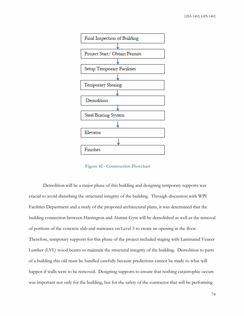
LDA-1403, GFS-1402
Demolition will be a major phase of this building and designing temporary supports was
crucial to avoid disturbing the structural integrity of the building. Through discussion with WPI
Facilities Department and a study of the proposed architectural plans, it was determined that the
building connection between Harrington and Alumni Gym will be demolished as well as the removal
of portions of the concrete slab and staircases on Level 3 to create an opening in the floor.
Therefore, temporary supports for this phase of the project included staging with Laminated Veneer
Lumber (LVL) wood beams to maintain the structural integrity of the building. Demolition to parts
of a building this old must be handled carefully because predictions cannot be made to what will
happen if walls were to be removed. Designing supports to ensure that nothing catastrophic occurs
was important not only for the building, but for the safety of the contractor that will be performing
Figure 42 - Construction Flowchart
74

LDA-1403, GFS-1402
the work. Methods for temporary supports were discussed but a sizing of shoring members was not
addressed.
5.2.1 Site Plan and Logistics
For the site plan and logistics of the renovation of Alumni Gymnasium there was the
concern of the storage of materials and equipment due to a lack of space on the perimeter of the
building. After an interview with Alfredo DiMauro, the Assistant Vice President of Facilities (See
Appendix A), it was decided that the space behind Harrington Auditorium would be the best place
for any heavy equipment and materials to be stored. This area shown in Figure 47, additionally, must
be fenced off to prevent injury and trespassing.
Figure 43- Site Plan
75

LDA-1403, GFS-1402
The area in front of Alumni/ Harrington connection (Bartlett Center Parking Lot) will be
used for materials storage and/or the position of the job trailer, as to block student traffic
completely between the Bartlett Center and Alumni. Second, the walkway on the East Side between
Alumni and Higgins should only be closed temporarily for exterior work to be done. An ideal
situation would be to perform this work activity when campus is not busy. Although winter break
might seem like a good time, exterior work uses scaffolding so the weather in Worcester would not
make this safe or cost efficient. A good time to propose for executing this activity as well as the
cutting in the access holes for the steel frame would be during the spring break in March 2015.
There must be fencing around North and South Side of Alumni at all times. This should extend
beyond the building’s footprint only as far as necessary to allow for staging (about 10-15 feet).
The best place for deliveries will be to the rear of building. This area is currently fenced off
so this protective fencing, which is behind Harrington, must be removed to create a roadway for
truck access. The trucks will access this point of the site from the existing road next to the parking
garage which is accessed from Park Avenue and Salisbury Street. This area may also have to be
excavated and brought to an appropriate grade to ensure safe delivery since the incline is currently
steep. If this area is designated for deliveries, a benefit would be that pedestrian traffic in front of
the building will not be disturbed and public safety would be less of a concern. Since the pedestrian
traffic behind Harrington and in Recreation Center roundabout is not as heavy in the winter as the
fields are shut down, important deliveries should be scheduled for that time. Also, it is essential that
there is proper procurement for materials to avoid delays as well an influx of material on a job site
that already has limited space.
The demolition of the Harrington-Alumni Connection is planned for the fall of 2015 which
means that there will be interior demolition going on during the school year. This may cause an issue
76

LDA-1403, GFS-1402
with the number of dumpsters and their location on campus. The use of only two or three
dumpsters at a time in front of Alumni (depending on yardage) is proposed; this will allow more
room for pickups and drop-off. Once most of the debris is discarded, a reduction in the number of
dumpsters is expected so only one or two should be placed in that location. This will save the
construction manager space as well as money during the other phases of project. Since debris will be
removed from the back of Alumni for this demolition, fencing-off of the walkway to the Campus
Center is advised so as to allow maximum space for all the debris removal.
Since the steel framing system entails the use of a crane, the two optimal places would be
either in the area behind Alumni or in the Bartlett Center Parking Lot. A movable crane with either
wheels or tracks would be convenient as the framing would have to be delivered to different parts of
Alumni, and the crane could be easily moved off site when the framing is complete.
5.2.2 Cost Estimates
With the use of R.S. Means Construction Building Cost Data, (2013 Edition), the 2014 National
Construction Estimator, and R.S. Means Square Footage Costs (2013 Edition) a construction cost estimate
of about $6.7 million dollars was generated. This may seem low given that the project budget is
between $10-$12 million. However, after adding in the location factor with the cost of 10%
overhead, 10% design fees, and a 10% profit to the total price, the cost was calculated to be $9.8
million. A detailed breakdown for these cost items is provided in Appendix L as well as a summary
table shown below in Table 3. This was a more realistic price as contractors bidding this job will
most likely want to estimate as low as possible. The highest cost for the estimate came from the
“Mechanical” WBS with a cost of about $1.9 million. The second highest was the “Conveying
System” (which includes the elevator shaft) at $1 million, with “Demolition” of Alumni Gym
77

LDA-1403, GFS-1402
costing about $ 0.5million. Although, the “Structural Components” did cost about $200 thousand,
they were not a major expense for this project since light weight solutions were made for beams and
columns in the framing system as well as for the open web steel joists in the pool slab. The scope of
the site cost did not include fill for the access road, but it was focused on utility upgrades and
landscaping which were more essential to the completion of the project.
5.2.3 Schedule
The project duration was calculated based on a start date of 11/10/14 using Primavera
software. The estimated duration result was 255 working days (about 12 months) which means that
this project would be completed by 10/30/15. Since the renovation to Alumni is intended to be
completed by the 150th Anniversary of WPI in November of 2015, this schedule would be feasible in
comparison to the benchmark provided by WPI and Goody Clancy. The critical path is shown in
Section Cost Demolition 2,363,374.00$ Square Foot 3,611,285.52$ Structural Assemblies 172,155.71$ Site 607,699.42$ Total Construction Cost 6,754,514.65$
Liability Insurance for One year is .24% of Construction Cost 16,437.18$ Permits $11 Per $1000 of Construction Cost 75,337.08$ 10% Design Cost 684,882.57$ 10% Overhead 684,882.57$ 10% Profit 684,882.57$ Location Factor 1.1
Alumni Gym Total Cost of Completion 9,791,030.28$
Table 3: Summary Table of Project Cost
78

LDA-1403, GFS-1402
network form in Table 4 below. It moves along the CSI divisions by month and details the event
that will be most time sensitive to this project. The critical path chart is shown in Tabular form in
Table 5 below. It identifies demolition and the installation of the new steel frame to be the most
critical items. Although many of the other elements of the project, such as the pool slab design and
the installation of a new elevator were essential to Alumni’s completion, the steel frame was the
most critical to complete. The cost for just the critical path activities is also shown and it is about $2
million. Table 6 below shows a summarized schedule by WBS category with the time of each CSI
division and at which dates they will be completed and their corresponding budgeted costs. This
chart is vital because it provides the construction management team a viable means to divide the
work between the different trades that will be on the project at the same time.
This Space Left Intentionally Blank
79

LDA-1403, GFS -1402
Table 4: Critical Path By Month
80

LDA-1403, GFS -1402
Table 5: Critical Path Activities with WBS and Costs
81

LDA-1403, GFS-1402
Table 6: CSI Timescale with Costs
This Space Left Intentionally Blank
82

LDA-1403, GFS-1402
5.2.4 BIM – New Model and 5D integration
The result of the 5D Model was a success. Due to software limitations the Project
Management schedule created with Primavera software had to be exported to Microsoft Project in order
to be integrated into Navisworks. Although this had some limitations, the simulation was completed
without any problems. Figure 48 below shows the simulation of the demolition of the concrete slab
and the stairs on Levels 3 to 4. Figure 49 below shows the installation of the new steel framing
system throughout the building as well. Lastly, in Figure 50 the installation of the pool web joists
and concrete pedestals are shown. The 5D model, which was the result of integrating the BIM
model, the spreadsheet cost estimate, and the Project Scheduling file, shows what the actual
construction of Alumni will look like in the near future, the schedule of work activities, and how
much it will all cost to complete. This 5D model contributes to the concept of Earned Value
Analysis, shown in Figure 51, which allows the contractor to measure the project’s process at any
point in time, forecasting its completion date and budget as work proceeds.
Figure 44 - Demolition of Slab (Left) and Stairs (Right)
83

LDA-1403, GFS-1402
Figure 46 - Open Steel Web Joists at Pool Level
Figure 45 - New Steel Framing System
84

LDA-1403, GFS -1402
Figure 47 - Earned Value Analysis for April 6th, 2015
85

LDA-1403, GFS -1402
6.0 Conclusions and Recommendations
The main objective of this project was to design and plan for the renovation of a historical
building project. This project provides value to WPI for the actual project because structural
solutions were developed, cost and schedule were analyzed, and documentation of the existing
structure was performed. The sequence of work and recommendations for expansion of this project
are discussed.
6.1 Sequence of Work
The work for this project included multiple phases that were supported by Building Information
Modeling tools and techniques. The phases of this project were:
• Existing building documentation
• Existing building structural analysis and building code compliance check
• Identification of modifications for new layout and major areas of renovation
• Development of structural designs to satisfy new layout and building code requirements
• Preparation of construction schedule and cost estimate with time and budget constraints
With BIM authoring tools and techniques all phases of this project were performed in a central
model and linked with the schedule and associated cost to develop a 5D model displaying all major
structural changes to Alumni Gymnasium. The 5D model allowed the visualization of the
construction phase before it takes place in order to identify any changes that might be made to the
schedule as well as gain a further understanding of the cost associated with each phase of the
project. Initially, documentation of the existing conditions of Alumni was gathered in order to
develop a 3D BIM Structural model of the existing structure in order to gain an understanding of
86
LDA-1403, GFS-1402
the existing structure. This was done through research in the “WPI Archives and Special and
Special Collection Department”, interviews with and site tours led by WPI Facilities Department
Management, and verification of information on original plans in the field. Once the overall
structural system was identified, the model was created to gain a further understanding of the
structural framing at each Level. The structural system of Alumni is a combination of different
systems and materials that included steel, concrete, brick, and wood. Once these systems and
materials were identified, a structural analysis of these elements was performed to investigate
building code compliance.
The structural analysis performed for this project was an investigation of all major elements
that comprised the structure of the building, but it was limited to those that could also be accessed
and measured. For example, the pool framing at Level 2 is made up of a concrete beam and column
system that could not be fully investigated due to lack of accessibility to measure the members and
check the reinforcing. Therefore, these elements were not investigated and are omitted from this
report. However, the framing for the other Levels of the structure were analyzed for gravity and
lateral loads. Gravity loads that were identified were dead, live, and snow loads; lateral loads were
wind and seismic in accordance with IBC 2009 (ASCE 7-05). Along with investigating the structural
elements of the building individually, the overall structure was analyzed to measure its capacity
against seismic forces. This was necessary because it was found that the unreinforced masonry did
not have sufficient capacity to resist the seismic load and was out of compliance with building codes.
The rest of the structure, however, met current building code requirements and therefore no further
reinforcing would be needed for these elements.
Alongside this analysis, identification of the major areas of renovation for the new, proposed
layout by Goody Clancy was conducted. This was done using the results of the structural analysis
87

LDA-1403, GFS-1402
that indicated a seismic upgrade was necessary as well as through study of architectural renderings in
Sketchup provided by Goody Clancy. These renderings outlined the changes in the use of space that
would take place in the renovation of Alumni. Ultimately, the major areas of renovation were
identified as follows:
• Seismic upgrade of the existing structure
• Shear Wall System for Showcase Atrium on Level 3
• An elevated slab over the pool opening for a Robotics Pit
• An elevator shaft for accessibility
After identification of these major areas, design development began in order to provide solutions.
Design development was a critical phase in this project because alternatives had to be
explored to determine the solution that would best integrate into the existing structure and also have
acceptable schedule and cost implications. It was concluded that a structural steel frame would
provide the simplest system for a seismic upgrade compared to reinforcing the existing brick and
mortar exterior walls. This would satisfy building code requirements for seismic considerations.
The development of the other designs as mentioned above were based off the proposed layout. The
use of BIM was an integral part of this process because these designs were included in the 3D model
which provided a visualization tool to understand how the various systems could be introduced into
the building. For example, the steel frame system that was defined within the inside perimeter of the
brick walls was oriented so that its elements were not visible through windows or openings. Once
completed in the 3D BIM model, the frame was analyzed using Visual Analysis software to resize the
members with the new orientation. Using these designs, the construction phase of the renovation
was developed further to include the construction schedule and cost estimate.
88
LDA-1403, GFS-1402
The cost estimate and schedule had to be prepared with the constraints of time and cost due
to the proposed budget and schedule established by WPI. A budget of $10-12 million and 20 month
construction schedule were initially estimated for this renovation. The end date was already
established to account for the 150th anniversary celebration of WPI’s founding. With this in mind, a
list of work activities was defined and sequenced to create the schedule, and costs were added to
each item. This information was then linked to the 3D BIM model using Navisworks software to
develop a 5D model that phases the major activities for structural changes. Architectural
information was not modeled for the most part nor was it linked between the model and schedule.
This information can be further developed using the model that was prepared as part of this MQP.
6.2 Recommendations for Alumni Gymnasium Renovation and Future MQPs
Although the scope of this project encompassed structural analysis and design, Building
Information Modeling, construction scheduling, and cost estimating, there is still much more that
could be done to provide a full investigation of Alumni. BIM could be further utilized to include
site planning or facility management. The current model can be further developed to include the
Architectural layout that was proposed for the renovation. Mechanical, Electrical, and Plumbing
(MEP) information for the existing systems can be modeled to gain an understanding of the existing
conditions and the impacts of the planned much like modeling the existing structural layout.
Additionally, for construction purposes, BIM tools and techniques can be used with this BIM model
to track construction activities during the project as well as refine the cost estimate as the scope of
work becomes more defined. Overall, there are many more BIM tools that can be utilized
depending on how much detail is necessary or warranted for this renovation. BIM tools and
techniques can be of great use for this project because of its visualization and communication
capabilities. With a renovation project, it may be difficult to understand the extent of work and
89

LDA-1403, GFS-1402
information must be constantly updated as this information becomes clearer. BIM provides a portal
to perform these tasks effectively.
Another dimension that could be expanded upon is researching LEED alternatives as well as
other alternative designs. LEED could play a major role in this renovation since much of the MEP
is outdated and inefficient. A LEED study would identify these areas of concern so that LEED
could be implemented as part of the renovation. A LEED study and implementation plan would
follow the precedent set on the WPI campus by other newly constructed buildings like the New
Sports and Recreation Center, East Hall, and Faraday Hall. However, Alumni would be unique
since it would be a renovation that incorporated LEED rather than new construction. This would
involve the use of BIM for building energy simulations of the existing building, defining the LEED
criteria to be used for planning for LEED and providing useful information that would identify
where LEED alternatives can be effectively integrated. This may have significant cost implications
since the existing MEP systems must be removed or coordinated with new MEP elements to avoid
clashes and properly upgrade the system. BIM could be useful in this application as well because of
its clash detection capabilities and ability to model MEP equipment.
In terms of alternative designs, other structural systems could have been analyzed when
developing a design for seismic upgrade. Carbon fiber polymer reinforcement is another material
used besides steel for seismic reinforcement. Further investigation into the pros and cons of this
system as compared to a steel frame would provide a more well-rounded approach to this design.
This system was briefly discussed but no true analysis was done on the benefits of this system.
A significant amount of information was collected in this project, but with any project of
this size, there are many more areas that could be further studied and explored that may provide
more benefit to this project and improve upon the work done. The Alumni Gym “Innovation and
90

LDA-1403, GFS-1402
Solution Center” project will have a clear impact on the WPI campus and the attraction of the
students to enroll in WPI. This project will not only expand on the WPI project-based curriculum,
but it will give a building once the center of campus and rich in history a chance to serve its
community once again.
91

LDA-1403, GFS -1402
Bibliography 1. Laramee, David C., and Benjamin Mies. Renovating Alumni Gymnasium for Academic
Purpose. Major Qualifying Project. Worcester Polytechnic Institute, 23 Mar. 2007. Web. 20 Sept. 2013.
2. Mell, Eileen B. (2009). WPI Trustees Vote to Proceed with Sports and Recreation Center. WPI Press Release
3. Worcester, MA. Charter, Laws and Ordinances of the City of Worcester, 1911. Worcester, MA: The Blanchard Press, 1911.
4. Guidelines for Renovating Historic Buildings. The Secretary of the Interior's Standards for Rehabilitation and Guidelines for Rehabilitating Historic Buildings. Web. 26 Sept. 2013.
5. Salter, Christopher. DiMauro, Alfredo Personnel Interview. 2 October, 2013 6. "Worcester Historical Commission Details." Http://www.worcesterma.gov/boards. Boards &
Commissions | City of Worcester, MA. Web. 04 Oct. 2013. 7. Katz, Ashley. "About LEED." U.S. Green Building Council, 25 July 2012. Web. 14 Oct.
2013. 8. "LEED Rating Systems." LEED Rating Systems. U.S. Green Building Council, 25 July 2012.
Web. 14 Oct. 2013. 9. "Building Information Modeling in Practice." Http://www.ddscad.com. Autodesk Building
Solutions, 25 Feb. 2011. Web. 14 Oct. 2013. 10. Clancy, Goody. ""A Dynamic Expression of the WPI Plan"" Worcester Polytechnic
Institute, 9 Sept. 2013. Web. 9 Sept. 2013.
11. Taylor, Herbert F. Seventy Years of the Worcester Polytechnic Institute. Worcester: December, 1937.
Print.
12. Howard, Thomas W. "What Shall the New Gymnasium Do for Tech." Journal of the Worcester
Polytechnic Institute. Vol. 19. 141-46. Print. 1915-1916. 13. WPI Journal, http://wpialumnimag.epubxp.com/i/211791/23 Pg.22 14. Autodesk. 2014. Products: URL<http://www.autodesk.com/products/autodesk-
navisworks-family/overview> 15. MECA Products. Wind. URL<http://www.mecaenterprises.com/MecaWind.html> 16. MECA Products. Seismic. URL<http://www.mecaenterprises.com/MecaSeismic.html> 17. Visual Analysis. 2014 URL<http://www.iesweb.com/products/visualanalysis/> 18. Sketchup. 2014. URL<http://www.sketchup.com/> 19. CANAM.2014. URL<http://www.canam-
steeljoists.ws/www/v4/epublica.nsf/va_download/510BE0CAEB44CD9D8525796B004D90E5/$File/eCtPout.pdf>
20. New Millenium. 2014. URL<http://www.newmill.com/pdfs/form-decking.pdf> 21. ASCE Code of Ethics. 2014. URL <http://www.asce.org/uploadedFiles/Ethics_-
_New/Code%20of%20Ethics%20October%202010.pdf
92

LDA-1403, GFS -1402
Appendix A – MQP Proposal
2. 0 Background
Worcester Polytechnic Institute (WPI) has a long standing tradition in the New England area
not only in academics, but in athletics as well. The development of WPI’s rich athletic history came
from the construction of Alumni Gymnasium in 1915. This building, up until the 2012 the
completion of the new “Sports and Recreation Center”, was the hub of all athletic activity for WPI.
Currently, however, WPI wants to shift this building’s use to academics by turning it into a Project
Center with an estimated budget of $12 million and a timeframe scheduled to begin sometime in
2015 [5] .
2.1.1 History of Alumni Gymnasium
Alumni Gymnasium was the first gym to be built for the WPI community and was erected at
the same time as Alumni Field. This building was placed near the center of campus and was to
provide a home for the expansion of the WPI athletics program at that time. It was considered a
state of the art facility as it had five-stories, three above ground and two below, including an
underground pool. Interestingly enough, the pool wasn’t completed until 1925, nearly 10 years after
the completion of Alumni Gymnasium. This was because there was a debate about whether an ice
rink should have been built in that area instead of the current pool [5].
Although Alumni Gymnasium today is considered an outdated facility, when it was built
there were many features that made it a distinctive facility. The basement floor was equipped with a
weight room and acted as the school’s fitness center. This floor also contained a balcony that
overlooks the underground pool in the sub-basement level where swim practices and meets were
held. The first floor includes the main entrance as well as the locker rooms and offices of the
A-1

LDA-1403, GFS-1402
physical education department. The second floor holds a basketball and two racquetball courts,
which are on each side of the stairwells. The top floor, which is the third floor, features an indoor
running track with another balcony overlooking the basketball court below.
After over fifty years of being the leader of the WPI athletics, the WPI community decided
to update its facilities again. In 1965, construction of Harrington Auditorium began. This building
was connected to Alumni Gymnasium in order to increase the convenience for student-athletes and
included a new basketball court and seating for spectators. The need for this building was to keep up
with the school’s growing athletic program and to increase the amount of space for physical activity
[1]. Continuing with this thread, the locker rooms were expanded in Harrington and a new fitness
center was added in Alumni Gymnasium as well in the 1980’s [5].
In May of 2010 construction of a new fully operational, state-of-the-art recreational facility
began on Worcester Polytechnic Institute’s campus in Worcester, MA. The $53 Million building
featured a 29,000 square foot gymnasium, a natatorium containing a 25-meter competition
swimming pool, rowing tanks, squash courts, robotics pits, 11,000 square feet of fitness space, and
an additional 5,000 square feet of multipurpose rooms. The combination of a recent growth in
student body population and the outdated athletic facilities currently offered at WPI made it
apparent that a new, state-of-the art recreational facility would be required on campus to
accommodate these needs. The completion of this facility in 2012 made it apparent that Alumni
Gymnasium would no longer be needed as an athletic facility so the process to change it into
something more beneficial to the WPI community began [2].
2.1.2 Structural Aspects
The design and construction of Alumni Gymnasium was completed by the guidelines of the
1911 Laws and Ordinances of the City of Worcester. During the early 20th century, design and construction
A-2

LDA-1403, GFS-1402
was performed by a “rule of thumb” and building codes were a collection of “good practices” [3]
Buildings that were three stories tall, similar to Alumni Gymnasium, were required to have brick
walls 16 inches thick for the basement and anything below as well as 12 inch thick walls for the first
three floors above ground. The floors as prescribed in Section 31 of this code, state that when a
public assembly is designed, the floor must support no less than 100 pounds per square foot [3].
From these codes there was clearly a lack of a performance- based approach and with the reliance of
engineering solely based on good judgment for maximum loads, many building in this era may have
been overbuilt [1].
When looking at Alumni Gymnasium, the walls of the first three floors should have a wall
thickness between 16 and 24 inches. From visual inspection they seem to be over 24 inches and this
is correct as the true dimensions from the drawings are about 30 inches [1]. This clearly shows that
Alumni Gymnasium was built like a “tank “as it has an outstanding structural shell. Unfortunately,
some of its others components such as the heating system, plumbing, windows, interior walls, lights,
and roof are in need of major renovations and must be brought up to the current building codes [5].
2.2.1 Maintenance of Historic Buildings
Many buildings built in the early 20th century consisted of brickwork. Not only was brick
easily manufactured, but it was the most sustainable material that required the least maintenance. But
like everything else, over time everything starts to deteriorate [4].
Renovation approaches for Historic Buildings generally fall into one of five categories. First,
stabilization: a process involving methods that reestablish a deteriorated property's structural stability
and weather tightness while sustaining its existing form. Second, preservation: a process involving
methods that maintain a property in its present state. Third, rehabilitation: a process involving
repairs and alterations to a property that adapt it to a contemporary use while preserving its historic
A-3

LDA-1403, GFS-1402
fabric and character. Fourth, restoration: a process that accurately recovers the appearance of a
property at a particular period of time by removing later additions and/or replacing missing features.
Or fifth, renovation: a generic term used to define all work that is meant to make new again [4].
2.2.2 Preservation and Restoration Techniques
Alumni Gymnasium was built with bricks and is considered a historic building as it is
roughly 100 years old. Many buildings of this nature usually have damage caused by deflection or
water infiltration, especially on the roof. There is a series of steps that must be followed in order to
successfully resolve the problem without damaging or jeopardizing the historic nature of the
building. First, if the mortar is missing or loose, the joints should be cleaned out and repointed using
a mortar mix which closely matches the composition, joint profile and color of the original. Second,
there must be careful removal of mortar from the joints so as not to damage the brick edges. Third,
whenever partial or total foundation replacement is required, the new foundation walls should be
faced in materials that match the original in appearance. Fourth, whenever replacement brick or
stone is needed, there must be a use of a material that closely matches the original in size, color and
texture. Fifth, whenever masonry has been painted, it must be repainted after removing all loose
paint. Sixth, any cleaning should be done with the gentlest method possible and should be stopped
at the first evidence of damage to masonry [4].
A-4

LDA-1403, GFS-1402
Figure 48 - Exterior View - South Side Alumni
Figure 49 - Exterior View - West Side Alumni
These methods above are crucial in maintaining the masonry of an historic building. Some
fundamental concepts that relate to all aspects of historic buildings and in particular to Alumni
Gymnasium are: First, every reasonable effort should be made to provide a compatible use for a
property that requires a minimal alteration of the building. Second, the distinguishable original
qualities or character of a building should not be destroyed, such as the removal or alteration of any
A-5

LDA-1403, GFS-1402
historic material or architectural features. Third, all buildings, structures, and sites should be
recognized as products of their own time, as in, alterations which have no historical basis and which
seek to create an earlier appearance are not necessary. Fourth, changes that may have taken place in
the course of time are evidence of the history and development of a building and should be
recognized and respected. Fifth, examples of skilled craftsmanship that characterize a building
should be treated with sensitivity. Sixth, deteriorated architectural features should be repaired rather
than replaced, wherever possible. However, if a replacement is necessary, the new material should
match the material being replaced in composition, design, color, texture, and other visual qualities.
Seventh, the surface cleaning of structures should be undertaken with the gentlest means possible.
Eighth, contemporary design for additions to existing structures or landscaping shall not be
discouraged. Ninth, wherever possible, new additions or alterations to structures shall be done in
such a manner that, if they were to be removed in the future, the essential shape of the original
structure would remain the same [4].
One of the most effective ways of maintaining the integrity of historic buildings in
Worcester, MA is through the Worcester Historic Commission. The function of this association is to
issue certificates of appropriateness, certificates of non-applicability, and certificates of hardship to
any construction project or alteration of an historic building. They conduct research about places of
historical interest and advice the Planning Board, the Worcester Redevelopment Authority, the
Executive Office of Economic Development, and other city agencies such as the National Park
Service and the National Trust for Historic Preservation on all questions involving historic sites.
Most importantly, this commission can cause a major delay to any project or alternation involving a
historic building. They can give recommendations to owners of historic buildings in Worcester on
issues of preservation and determine what can and cannot be done to the building in order to
preserve its historic significance. If the owner doesn’t agree upon these suggestions or the given
A-6

LDA-1403, GFS-1402
proposal, the commission, through the city of Worcester, can delay the beginning of construction
for up to a year [6]. Most owners that are faced with this dilemma usually just wait out the delay and
then start construction; however, this has a seemingly large effect not only on the modifications to
the building itself, but political perspective as well [6].
2.3.1 Structural Evaluation of Buildings
In a building renovation project of this magnitude, an evaluation of the structure must be a
primary consideration in order to determine the adequacy and suitability of the structural systems in
place, and if they meet building code. The major structural systems that are to be investigated
include all existing foundations, floors, walls, and roofs.
2.3.2 Structural Building Systems
Foundations are the bottom most part of a building’s structure; they are placed below grade
in order to transfer loads from the upper structure into the soil. The primary consideration during
design of foundations is to limit differential settlement of the structure. This is to ensure that the
above structure is not altered or disturbed by the foundation settling at different elevations. Some
ways to limit settlement are to ensure adequate soil capacity and to spread the load out over a
sufficient area to minimize bearing pressure. Foundations are primarily comprised of footings and
walls. Footings can either be considered deep footings, or shallow spread footings. The option on
which type of footing to use is dependent on the type of soil conditions present at the site. Deep
footings can be either wooden piles, steel piles, or pressure injected concrete footings (pifs). Shallow
spread footings are usually made from reinforced concrete. Foundation walls sit on footings and are
primarily constructed with reinforced concrete, stones, or bricks as they must be designed
adequately to resist the gravity loads imposed on it from the above structure.
A-7

LDA-1403, GFS-1402
Floors and walls are horizontal and vertical members, respectively, of buildings that serve a
variety of purposes. Other than the obvious purpose of an area for people to walk on or providing
shelter from the outside conditions, floors and walls serve to resist both gravity and lateral loads.
The gravity loads a floor as well as a wall must carry are both dead and live loads. The dead and live
loads are determined by a floor’s intended uses, which are spelled out in building codes. Also,
Floors and walls are supported by beams and columns, which transfer loads down the structure, and
eventually make their way into the foundation and soil. Floors and walls also act together to resist
lateral loads by acting as a diagram. With the combination of floor and roof geometry, these
members can act as rigid members to resist wind and seismic loading. In addition to the floor and
wall diaphragm system to resist lateral loading, beams and columns, constructed as a moment frame,
can resist against lateral loads as well.
The roof is the highest member of a structure. Generally, the roof must be designed to carry
dead and snow loads, which are again determined by the building codes. The roof can be
constructed from steel, wood, concrete, or any other suitable material and most systems are built as
trusses, or a beam/ column assembly.
2.3.3 Building Codes
Building construction in Massachusetts is controlled by the following building codes. For
Non-residential and residential structures above 2 families, the following codes govern building
construction:
1. International Building Code (IBC) 2009 Edition
2. MA Amendments to IBC-2009
A-8

LDA-1403, GFS-1402
3. Minimum Design Loads for Buildings and Other Structures by the American
Society of Civil Engineers (ASCE 7) 2005 Edition
4. International Existing Building Code (IEBC) 2009 Edition
Since the Alumni Gym is an existing building the construction is only controlled by either
Chapter 34 of IBC or the separate IEBC Code. In Massachusetts, one of the MA Amendments of
the IBC is to delete Chapter 34 and adopt the IEBC in its entirety. In addition to the above codes,
the following material codes are adopted by reference in the IBC and control the design of structural
members:
1. Concrete - Building Codes Requirements for Structural Concrete (ACI 318-11) by the
American Concrete Institute
2. Masonry - Building Code Requirements and Specification for Masonry Structures (TMS
402/ACI 530/ASCE 6) by the following 3 societies:
The Masonry Society (TMS 402)
American Concrete Institute (ACI 530)
American Society of Civil Engineers (ASCE 6)
3. Structural Steel - Specification for Structural Steel Buildings (ANSI/AISC 360) by:
American National Standards Institute
American Institute of Steel Construction
4. Wood - National Design Specification for Wood Construction (NDS) by:
American Forest & Paper Association
American Wood Council
A-9

LDA-1403, GFS-1402
2.5.1 Building Information Modeling
In recent years, great investment has gone into the use of Building Information Modeling
(BIM) as a tool for design and construction. BIM is an intelligent model-based process that
provides insight and solutions for buildings and infrastructure projects. This software allows
businesses to build projects faster, more economically, and environmentally conscious [9]. BIM
allows contractors of all trades to create a 3D model of their work that can later be compiled into
one realistic building model. From there, any detection of clashes (when more than one element is in
the same space) is found and resolved before construction begins. This software prevents the waste
of extra time and money if a mistake was to be made on sit, especially in the current economy.
Using BIM assists in eliminating these mistakes and increases profitability and productivity of the
building. Almost half (46%) of the infrastructure organizations, surveyed by Autodesk, are currently
using BIM technologies and processes on some part of their infrastructure portfolio; a recent growth
from only 27% two years ago. The vast majority (89%) of these companies that currently use BIM
for infrastructure report that it is extremely beneficial in keeping a project on time and on budget [9].
They also experience benefits that impact their internal business functions as well.
2.5.2 BIM’s Importance in Design
BIM has many key benefits during the design phase of a project. Project scope, schedule,
and cost all must be managed well during the design phase as this is the phase where many changes
are made to these variables. Through traditional methods, if changes to the variables mentioned are
made later in the project, delays can occur and great effort has to be made to upkeep the project.
This can cause delays with increased costs negatively affecting relationships between consultants and
clients. With BIM these changes can be made and immediately eliminate many costly delays [9].
A-10

LDA-1403, GFS-1402
If a client were to decide to change the scope of their project, BIM can conveniently provide
the tools necessary to make the changes. When one design value is changed, further calculations to
other structural elements do not need to be made as BIM will automatically update the changes
throughout the project. This allows the design team effective and speedy delivery of documents and
visual elements.
Due to the nature of our project, BIM will be useful if any changes need to be made to the
structural shell of the facility such as relocating windows, updating gravity loads to meet code
requirements, or designing for lateral stability which is currently non-existent in the structure. It will
also help determine the constructability of various designs and the integration into the existing
structure.
2.5.3 BIM’s Importance in Construction
Another useful feature in BIM is the available information on building quality, schedule, and
cost [9]. Cost estimating and value engineering can be accelerated especially when updates are made
to any plans or estimates. Also, site plans can be prepared and used for communication to minimize
the impact of construction operations on the owner. Due to a higher quality of documentation and
better construction planning through BIM, administrative and overhead costs can be reduced [9].
With Alumni Gymnasium being a renovation project, there are many variables, some of
which may not be clear initially, and having the ability to make constant updates to costs and
planning is crucial. Additionally, with the building being in the center of campus, proper planning
must be executed as to not interfere with the campus and the student life.
A-11

LDA-1403, GFS-1402
3.0 Methodology
3.1.1 Existing Conditions Analysis
The first objective for our project is to document the existing conditions of Alumni in a 3D
BIM model and 2D CAD drawings. After this documentation is complete, an analysis of all
structural members and systems will be conducted. This analysis will identify all structurally
deficient areas in Alumni, and provide direction as to what needs to be redesigned.
Developing a model of the existing conditions in Alumni Gym involves an information
gathering process specific to the building. This information will be gained from any available old
drawings of the building, and inspection visits to the site. Site visits will be used to both verify
conditions stated on old drawings, and to get any additional information that is required to analyze
the building. In the case of our MQP, there were only old Architectural drawings available, so a
thorough investigation into the structural systems in place will need to be done.
The structural investigation will consist of locating and noting size and spacing of all
structural systems and their members. These structural systems will include roof framing, floor
framing, exterior bearing walls, and foundations. To understand the roof framing, the roof truss
individual members, connections, and spacing will be measured. In addition, the purlins and deck
spans and sizes will need to be noted as well. This will involve a visual inspection from the floor 5,
and if possible, use of hydraulic lifts to get a closer look at the trusses. The floor framing will be
determined by locating and sizing all columns, beams and joists, as well as locating any holes that
exist in the floor diaphragm. Preliminary investigations indicate Levels 4 and 5 framing consists of
steel girders and timber beams spanning girder to girder. To properly analyze the timber beams, a
sample of the wood will be sent to a wood scientist to determine the species. The girders are
supported down to the floor by steel columns. Inspection holes will have to be cut in the sheetrock
A-12

LDA-1403, GFS-1402
walls in order to view the columns buried in the walls. Level 3 consists of a concrete slab, supported
by concrete beams and columns. Level 2 and 1 each bear on grade. Next, the thickness of the
exterior brick bearing walls will need to be measured at a window opening at each floor. Finally, to
the extent possible, investigations into the size of the foundation walls and footings will be done.
Once the above mentioned information is obtained, drafting of the 2D and 3D models will
commence. AutoCAD and MicroStation Power Draft will be used to draw the 2D drawings, and
Revit will be used to draw the 3D model. These models will serve as our existing set, and be used in
the analysis and eventually the redesigning process.
According to International Existing Building Code (IEBC) 2009 Edition, the size of project scope
determines which codes the building must comply with. Due to the degree of scope presented so
far for Alumni, it was determined that this project fell under the description of a level 3 renovation.
A level 3 renovation means that Alumni must be analyzed and comply with current building code
specifications. Each existing structural system will be analyzed to understand if they are in
accordance with the current codes. The checks of the structural systems are divided into two main
load checks, gravity loads, and lateral loads.
A-13

LDA-1403, GFS-1402
3.1.2 Gravity Load Analysis
1. Check of Existing Roof Load Capacity
a. Calculate roof snow load
b. Calculate dead weight of roof structure and all superimposed dead loads on roof
c. Analyze roof structure by one of two ways:
i. Measure and document each truss member size and span, and conduct a
truss analysis using current code design loads.
ii. Determine design loads from early 1910s building codes and compare to
current code design loads.
2. Check Floor Framing Load Capacity
a. Calculate dead load for each floor
b. Calculate live load for intended new usage of space
c. Check the existing floor framing for loads
3.1.3 Lateral Load Analysis
1. Check of Unreinforced Masonry Walls
a. Calculate wind load
b. Calculate seismic load
c. Check walls to support these loads
These checks will identify the deficient areas of the building, and give our group an understanding of
what areas need to be redesigned to meet current building codes. After this analysis is complete, a
clearer scope will be identified, and re-design can take place.
A-14

LDA-1403, GFS-1402
3.2.1 Building Information Modeling
While we are determining the solutions for renovating Alumni Gym, the uses of BIM will
help us define a final project and project scope. BIM will allow us to have a 3D model of the
building so we can see exactly what changes will need to be done and what structural challenges we
will face.
3.2.2 BIM for the Existing
As we analyze the existing Alumni Gym structure, BIM will be a very important aspect to
our project. Although we may not currently have all the information required for a BIM model, our
team will go in the field and collect information about the current at Alumni Gym to create an
accurate BIM model. Since there are numerous elements of construction that are not visible to the
naked eye, we plan to have some selective demolition done in the building so we could see the
unknown structural materials. As soon as we identify the layout of the building, we will create the
current version of our 3D model with the uses of Revit Architecture and Revit Structures.
In relation to the proposed layout provided by Goody Clancy, we will match the site to the
desired format such as the floor level names and scales. We will then begin designing the building on
Revit based off of the dimensions and materials we encounter as we investigate the site.
Building the BIM model is useful for the future of our project because it gives us a starting
point for the proposed renovation. As we see what materials are where, we will have a better idea of
what problems we will encounter and what changes need to be made. The Structural and the
Architectural versions will be linked together which makes it easier to view desired areas of the
building at any angle.
A-15

LDA-1403, GFS-1402
3.2.3 Proposed Model
After discussion and research of what the owner wants, we will create a BIM model off of the
existing model we’ve created. This model will be an important benefactor for WPI to use for its
future proposal and renovation.
3.2.4 Alternative Designs
As we encounter different situations regarding the structure and changes that are needed, we
will create different alternatives as sections in the BIM model. Each alternative we analyses will be
set as a separate drawing for viewing purposes.
3.2.5 Cost Estimation
Throughout the design, we will be able to simplify the quantity and the quality of the
materials used in the construction of Alumni Gymnasium. With the help of the RS Means Building
Cost and the development of our model, we will be able to estimate the unit prices for the materials
and what would be needed for the replacement of materials. With the development of this 3D
model, considering all the alternatives for the proposed renovation, we will estimate a cost for the
desired alternative in order to make this project realistic and feasible.
3.2.6 Schedule
With the creation of the BIM model we will create a schedule for construction alternatives. We
will create a schedule for the timing of the construction renovation and for site logistics of
transporting and storing material.
A-16

LDA-1403, GFS-1402
3.3.1 Design Development
Our largest contribution to the WPI community will be the development designs for the
change in use of Alumni Gym. Our group will focus on specific areas for our designs, but if other
issues are to arise during this phase, we will work to solve them as well. This phase of the project is
extremely crucial because the designs we develop will determine the cost, schedule, and integrity of
the building.
3.3.2 Design of Lateral Reinforcement
After the structural analysis is completed and the intended uses of the renovated Alumni
Gym are determined, the group will begin design on the major elements that are required. From
studying the International Building Code (2009) and due to the nature of the project, a lateral
reinforcement system design is needed to support the unreinforced masonry walls. Currently, the
roof truss members sit on the brick wall and are not properly supported if there were any lateral
movement in the structure. Our group proposes to use steel columns to support these roof truss
members, spanning vertically from the truss down to the basement in sections. The design of these
column members will help support the roof of Alumni in case the masonry walls fails laterally
because it will be able to withstand the weight of the roof if the walls collapse. This was determined
to be more feasible than reinforcing the walls with rebar which is more labor intensive in our
opinion. We aim to show the benefits of our system over using rebar for reinforcement in our
report.
In addition to lateral reinforcement for the overall building, reinforcement will be necessary
for the parapet walls on the exterior roof of the building. Currently, they are freely standing
unreinforced masonry walls. After checking these walls for wind and seismic loads, our group will
develop a design to reinforce these parapet walls. We propose to support these walls with angle
A-17

LDA-1403, GFS-1402
braces that will brace the walls in case of failure due to these failure methods. Reinforcing these
elements is important because they are part of the aesthetic appeal of the building and protecting
this element will help preserve the historic architecture of Alumni.
3.3.3 Design of Elevated Slab
Due to a change in use in the Alumni Gymnasium, the swimming pool that is currently
present is no longer useful. This area, according to proposed architectural plans, will be converted
in a showroom to display students’ projects. Therefore, our group proposes to design an elevated
slab that will cover the area the swimming pool currently occupies. We will design for gravity loads
according to code for the intended use of the area and to resist any stresses due to self-weight since
it will be elevated above the swimming pool.
3.3.4 Design of New Stairway
Another change that our group will be developing a design for is a new stairway on the
South side of the building. WPI intends to open the space up on the main floor of the building by
creating a central corridor that runs from the main entrance to an exit in the rear. Partitions walls
will have to be demolished to create this corridor and an opening in the exterior wall on the South
side will have to be created. From this exterior wall opening, there will be a staircase to enter or exit
the building. Our group will use building codes to determine the type of stairway that is needed in
this location. Criteria will include handicap accessibility, depth, width, and height of each stair,
number of stairs needed, and overall dimensions of the stairway. We will want a design that
complies with current codes and that meshes well with the existing structure to create an
aesthetically pleasing view.
A-18

LDA-1403, GFS-1402
3.3.5 Design of Temporary Supports
Demolition will be a major phase of this building and designing temporary supports will be
crucial to avoid disturbing the rest of the structure. Through discussion with WPI Facilities and
study of proposed architectural plans, it has been determined that the connection between
Harrington and Alumni Gym will be demolished as well as partition walls within Alumni.
Therefore, our group must design temporary supports for this phase of the project whether it be
shoring or temporary frames so that the structural integrity of the building is protected. Demolition
to parts of a building this old must be handled carefully because we cannot predict what will happen
if walls were to be removed. Designing supports to ensure that nothing catastrophic occurs is
important not only for the building, but for the safety of the contractor that will be performing the
work.
3.4.1 Construction
Cost estimating and scheduling are two important aspects of construction. This information
must be assembled, evaluated, documented, and managed in an organized manner, and for them to
work effectively, key information must be defined and accumulated at critical times. Also,
determining the sequential order of the planned activities, assigning realistic durations to each
activity and determining the start and finish dates for each activity is crucial to the success of the
project. They both will give the owner an idea of the price for the required renovations and how to
finish the project on time.
3.4.2 Cost Estimating
In order to evaluate the feasibility of our alternative designs, we will first standardize the cost
preparation process with the use the R.S. Means Construction Building Cost Data (2012 Edition) and CSI
Master Format divisions to organize our information and keep everything consistent. We will go
A-19

LDA-1403, GFS-1402
through each division of the CSI Master Format and do quality and quantity takeoffs for any items
that will be essential to the renovation and determine the required amount. Using the R.S. Means
Construction Building Cost Data (2012 Edition) we will look into the unit pricing costs for each item as
well as the square foot costs of similar buildings compared size to Alumni Gymnasium. This will
give us an idea of how much material will be needed to complete the project and how much it will
all cost. This will also allow us to compute an approximate continuity as well as make adjustments
to the final price using the location factor.
Since WPI as well as this project team already know from our first two site tours that there
will need to be numerous changes made to the building to bring up it to the current building code,
we both have similar objectives and methods that will help us plan according. The building currently
doesn’t have appropriate lateral support, as described in the previous sections, so determining the
cost of the material and time spent on fixing this problem will be critical in computing the most
accurate estimate as possible. Since our estimate isn’t going to be exact we are aiming for a level
within 10% of the actual price when outside companies bid the project. Our collection of data and
cost analysis will be as precise to the current drawings and documentation of Alumni Gymnasium as
possible and we will present the estimate in the most convenient format for WPI. These steps will
enable us to keep track of our work easily and make it simple to fix any discrepancy or inaccuracy in
a timely fashion.
A-20

LDA-1403, GFS-1402
3.4.2 Scheduling
The first step in our scheduling process will be to develop a work breakdown structure
(WBS) that identifies all the work items that must be completed to renovate Alumni Gymnasium.
We will consider activities that require the most time and cost, such as demolition, as well as
monitor items that we feel might change while studying the structure. This will help us arrange the
WBS in an efficient and easy way to follow when discussing the possible removal of a floor or the
temporary support of a beam (shoring) during construction.
The next step will be to use Primavera in preparing a drawing (network diagram) that shows
each activity in the order it must be performed to complete the project. After deciding which items
will be critical to the renovation, we will consider which activities immediately precede each activity
and which activities immediately follow each other. This will help us create the essential critical path
for the project and the timeframe for each activity. The connection of all these activities will be a
combination of how the work must be done (constraints) and how we want the work to be done.
Subsequently, we will determine the time, cost, and resources required to complete each
activity by reviewing the work packages and then finally compute the schedule to determine start,
finish, and float times. We will perform a forward pass to determine the early starts and finishes as
well as a backward pass to determine late starts and finishes. This will be key in determining the
differences between the start and finish times which determine the float time and the critical
activities.
Lastly, we will analyze the costs and resources for the project by computing the cost per day
for each activity and for the entire project as well as the labor-hours per day we think will be
necessary. We will then incorporate this data into BIM and display the time and cost schedule for all
the activities.
A-21

LDA-1403, GFS-1402
Bibliography for Proposal
22. Laramee, David C., and Benjamin Mies. Renovating Alumni Gymnasium for Academic Purpose. Major Qualifying Project. Worcester Polytechnic Institute, 23 Mar. 2007. Web. 20 Sept. 2013.
23. Mell, Eileen B. (2009). WPI Trustees Vote to Proceed with Sports and Recreation Center. WPI Press Release
24. Worcester, MA. Charter, Laws and Ordinances of the City of Worcester, 1911. Worcester, MA: The Blanchard Press, 1911.
25. Guidelines for Renovating Historic Buildings. The Secretary of the Interior's Standards for Rehabilitation and Guidelines for Rehabilitating Historic Buildings. Web. 26 Sept. 2013.
26. Salter, Christopher. Personnel Interview. 2 October, 2013 27. "Worcester Historical Commission Details." Http://www.worcesterma.gov/boards. Boards &
Commissions | City of Worcester, MA. Web. 04 Oct. 2013. 28. Katz, Ashley. "About LEED." U.S. Green Building Council, 25 July 2012. Web. 14 Oct.
2013. 29. "LEED Rating Systems." LEED Rating Systems. U.S. Green Building Council, 25 July 2012.
Web. 14 Oct. 2013. 30. "Building Information Modeling in Practice." Http://www.ddscad.com. Autodesk Building
Solutions, 25 Feb. 2011. Web. 14 Oct. 2013.
A-22

LDA-1403, GFS -1402
Appendix B – Meeting with Fred Dimauro Meeting with Fred DiMauro
Key Meeting Points:
• Construction Plan o Original idea was to tear down Alumni/ Harrington Connector first (fall 2014) and
then begin renovating Alumni Gym. Due to lack of funding this will not happen.
o Another idea was to store storm/ rain water in the Alumni pool and use it to irrigate the quad Seems unlikely as it is not cost efficient
o 18- 20 months of construction 10- 12 million dollar range Due to funding the project cannot start until they have saved 8 million;
currently have 3 million and are reaching out the trustees for donations o Next November 150th anniversary kickoff 150th anniversary with this project
This is likely start date, but it all relies on funding • Site Logistics
o Space available for storage, equipment, and dumpsters will be the Alumni/ Bartlett Center parking spaces and the grass hill near Higgins House. Quad connector can also be used if needed
o Deliveries can be made either through the front of Alumni or the back of Alumni • Structural Challenges
o Raised curb 6” around pool Must be removed in order to place slab
o Have not spoken to the Worcester Historical Commission as it is out of his area of expertise WHC only applies to portions of building visible from a city street; biggest
issue will be the windows if they must be kept original o Building square footage is being reconfigured; if the ratio of the cost for renovation
per square footage is less than a certain number, certain building improvement that would have to be used to bring Alumni up to the current building code can be avoided.
B-1

LDA-1403, GFS-1402
Appendix C – Level 3 Framing Concrete Slab
Concrete Slab Check:1-ft Strip Method
1.00 Minimum Slab Thickness
Both ends continuousSolid one-way slabs
minimum thickness, h = L/28= 15*12/28
6.43 in < 9in; OK
*ACI 318-08, Table 9.5(a) Minimum Thickness of Nonprestressed Beams or One-Way Slabs
2.00 LoadsDead Load (DL) = (150*9/12)+(150*2/12)
137.5 lbs/ft per ft of slabuse DL = 150 lbs/ft^2
Live Load (LL) = 100 lbs/ft^2*IBC 2009, Table 1607.1
w total = 250 lbs/ft per ft of slab
3.00 ReactionsR1 15*250/2R1 = 1875 lbs
4.00 Shear CheckΦVc = (.75*(f'c)^.5)*12*7.5
Req. f'c = (1875/(.75*12*7.5))^2772 lbs <2,000 psi
C-1
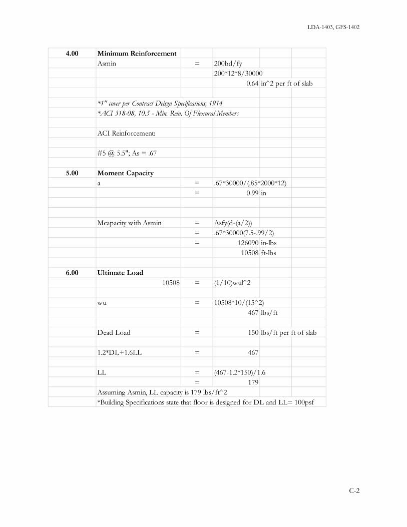
LDA-1403, GFS-1402
4.00 Minimum ReinforcementAsmin = 200bd/fy
200*12*8/300000.64 in^2 per ft of slab
*1" cover per Contract Deisgn Specifications, 1914*ACI 318-08, 10.5 - Min. Rein. Of Flexural Members
ACI Reinforcement:
#5 @ 5.5"; As = .67
5.00 Moment Capacitya = .67*30000/(.85*2000*12)
= 0.99 in
Mcapacity with Asmin = Asfy(d-(a/2))= .67*30000(7.5-.99/2)= 126090 in-lbs
10508 ft-lbs
6.00 Ultimate Load10508 = (1/10)wul^2
wu = 10508*10/(15^2)467 lbs/ft
Dead Load = 150 lbs/ft per ft of slab
1.2*DL+1.6LL = 467
LL = (467-1.2*150)/1.6= 179
Assuming Asmin, LL capacity is 179 lbs/ft^2*Building Specifications state that floor is designed for DL and LL= 100psf
C-2

LDA-1403, GFS-1402
Appendix D – Level 4 Framing (Timber Beams)
1.00 Typical 12x12 Wood Beamb = 12 ind = 12 inA = 144 in^2S = (12*12^2)/6 in^3
= 288 in^3
I = (12*12^3)/12 in^41728 in^4
spacing = 6 ftTw = 6 ft
span = 16 ft
2.00 Calculate Dead & Live LoadsDeck: 3" Wood + 1" Flooring
= 4*12*.25= 12 lbs/ft^2
Beam: 12"x12"wt/ft = 12*12*.25
= 36 lbs/ft
wt/ft^2 = 36/6= 6 lbs/ft^2
18 lbs/ft^2 ; use 20 lbs/ft^2
Wdead = 6*20120 lbs/ft
Wlive = 6*100= 600 lbs/ft
Wtotal = 720 lbs/ft
D-1

LDA-1403, GFS-1402
3.00 Calculate Stresses, fv & fbWtotal = 720 lbs/ft
R = 720*16/2 lbs5,760 lbs
d/2 = 6 in
V @ d/2 = 5760-6*720/12 lbs5,400 lbs
fv = 1.5V/A= 1.5*5400/144= 56.25 lbs/in^2
M = (wL^2)/8= (720)(16^2)/8
23,040 ft-lbs
fb = M/S23040*12/288
960 lbs/in^24.00 Member Check
Design Values from NDS, Table 4DAssume Douglas-Fir #1
Fv = 170 lbs/in^2 > 56.25 okFb = 1350 lbs/in^2 > 960 ok
5.00 DeflectionE = 1,600,000 lbs/in^2
Δ = (5wL^4)/(384EI)= (5*720*1728*16^4)/(384*1600000*1728)= 0.384 in
16*12/.384 = 500L/500 = 0.384
D-2

LDA-1403, GFS-1402
Appendix E- Level 4 Framing (Steel Girders)
1.00 Steel Girder (Col #6 to Col #7) - W18x76 (worst case)b = 11 ind = 18.2 inA = 22.3 in^2S = 146 in^3I = 1330 in^4
spacing = 16 ftTw = 16 ft
span = 28 ft
2.00 Calculate Dead & Live LoadsWdead = 16*20
320 lbs/ft
Wlive = 16*100= 1600 lbs/ft
Wtotal = 1920 lbs/ft
E-1

LDA-1403, GFS-1402
3.00 Calculate Stresses, fv & fbWtotal = 1920 lbs/ft
R = 1920*28/2 lbs26880 lbs
26.9 k
M = (wL^2)/8= (1920)*(28^2)/8
188160 ft-lbs188 ft-k
fb = M*12/S188*12/146
15.5 k/in^2(Fy=33k/in^2)Fb = 20.0 k/in^2 ok
fv = V/(tw*d)= 26.9/(.425*18.2)= 3.5 k/in^2
Fv = 13 k/in^2 ok
4.00 DeflectionE = 29,000,000 lbs/in^2
Δ = (5wL^4)/(384EI)= (5*1920*1728*28^4)/(384*29000000*1330)= 0.69 in
28*12/.69 = 487L/487 = 0.69
E-2

LDA-1403, GFS-1402
Appendix F – Existing Columns
1.00 Typical Pipe 8 STD (8.63")Area = 7.85 in^2r = 2.95 in
ln = 11.0 ft
2.00 Load on Column(2x reaction from steel girder on column)
Girder R = 26.9 k2R = 53.8 k
3.00 Slenderness Ratiokl = 1*11
11.00 ft
4.00 Available Strength in Axial Compresion (kips)ASD:Pn/Ωc = 148 k >53.8k OK
F-1

LDA-1403, GFS-1402
Appendix G – Wind Analysis
1.00= 14ft*12.68lb/ft^2= 177.5 lb/ft *per ft of wall
= [9+(22/2)](25.78)= 515.6 lb/ft
2.00
= ((22/2)+(10.6/2))*(25.78)= 420.2 lb/ft
3.00
= ((10.6/2)+(11/2))*(25.78)= 278.4 lb/ft
4.00 Increased Wind Load at Corners
= 33.73 lb/ft^2= 25.78 lb/ft^2
= 7.95 lb/ft^2 ; use 8.00
= 15.09 lb/ft^2= 12.68 lb/ft^2
= 2.4 lb/ft^25.00
= 14*2.4= 33.6 lb/ft
= 14*2.4= 33.6 lb/ft
6.00= 16.3*8= 130.4 lb/ft
7.00= 10.8*8= 86.4 lb/ft
P3 at CornerWall
Wall
P4 at CornerWall
DifferenceP6 at Corner
Roof
At "C" w
Difference
At "B" wAt "D" w
Wind Load P3
Wind on Wall
2a region from end wallAt "A" w
Wind on Wall:
Wind Load P4
Wind on Wall
Wind Load P6Wind on Sloping Roof:
G-1

LDA-1403, GFS-1402
8.00 Wind to Level 4 Walls (Old Floor 2)
= 127.33 ft
Loads at Exterior Transverse Wall (L=86.67ft)
Calculate R1 & R2 for P6 Load= (693*127.33/2)+(193.7*34.8/2)
47490 lbs
= 47490/(86.67*1.75*144)2.2 lb/in^2
= 47490/86.67548 lb/ft of wall
9.00 Wind to Level 3 Walls (Old Floor 1)
= 127.33 ft
Loads at Exterior Transverse Wall
= 86.67-windows= 86.67-7*3.5
62.2 ft
= 86.67-8*3.558.7 ft
Calculate R1 & R2 for P4 Load= (420.2*127.33/2)+(130.4*34.8/2)
29021 lbs
= 29021/(58.7*2.3*144)1.5 lb/in^2
= 29021/86.67334.8 lb/ft of wall
Check Shear Stress added to Wallfv
V per foot of Wall
L of Wall at right side
R1 = R2
Diaphragm Span
L of WallL of Wall at left side
V per foot of Wall
(P4)
R1 = R2
Check Shear Stress in Wallfv
(P6)
Diaphragm Span
G-2

LDA-1403, GFS-1402
10.00 Wind to Level 3 Walls (Old Basement)(P3)
Calculate R1 & R2 for P3 Load= (278.4*127.33/2)+(86.4*34.8/2)
19228 lbs
11.00 Shear & Moment Calculations
= 47490*22= 1,044,780 ft-lbs
= (47490)*(22+10.6)+29021*10.6= 1,855,797 ft-lbs
= (47490)*(22+10.6+11)+(29021)*(10.6+11)+(19227*11)= 2,908,915 ft-lbs
M2
M4
M3
R1 = R2
G-3

LDA-1403, GFS-1402
12.00 Transverse Walls - Basement Level
= 95738 lbs
= 29 in
= 87.5 ft
= 6.83 ft10.5 ft5.5 ft4.75 ft4.75 ft4.75 ft5.5 ft10.5 ft6.83 ft60 ft of brick wall
*Solid Brick Fully Grouted/Mortared
= 95738/(60*12*29)= 4.6 lb/in^2
= .5(f'm)^.5 </= 28lb/in^2
*Brick Institute of America, 1969
= 4.6= 84.6 lb/in^2
Brick with 2,000 lb/in^2 units & Type N mortar;= 530 lb/in^2 >84.6; OKf'm
*N type mortar*No inspection
Required f'm:.5(f'm)^.5
Required f'm
fv
Fv
Total Wall Length
Pier Lengths
Check ShearV
Wall thickness
G-4

LDA-1403, GFS-1402
13.00 Check Flexure at Piers
= 95738/87.41095 lbs/ft
= 1095*8.2= 8979 lbs
= 8979/(4.75*12*29)= 5.4 lbs/in^2
Moment Distribution by I (stiffness fraction)
= (L Pier^3)/(Σ(L Pier^3))
= 318.6= 1157.6= 166.4= 107.2= 107.2= 107.2= 166.4= 1157.6= 318.6
= 3606.7
L Pier^3L Pier^3L Pier^3L Pier^3
Σ(L Pier^3)
L Pier^3L Pier^3L Pier^3L Pier^3L Pier^3
Shear Stress in Pierfv
% to each Pier
Shear per ft of wall
Shear to Pier
G-5

LDA-1403, GFS-1402
= (4.75^3)/(3606.7)= 0.030
= .03*2908914.6= 87267.4 ft-lbs
= 29*((4.75*12)^2)/615703.5 in^3
= 87267.4*12/15703.5= 66.7 lbs/in^2 T or C
= (10.5^3)/(3606.7)= 0.32
= .32*2908914.6= 930,852.7 ft-lbs
= 29*((10.5*12)^2)/676734 in^3
= 930852.7*12/76734= 145.6 lbs/in^2 T or C
Add Gravity Load to 4-9 pier
= 120 lb/ft^3= 1.75*120*49*8.2= 84378 lbs
= 84378/(4.75*12*29)= 51.0 lb/in^2 C
Brick Unit wt for 12" wallBrick Wall wt
fc
S of 10-6 pier
fb
% to 10-6 Pier
M to 10-6 pier
S of 4-9 pier
fb
% to 4-9 Pier
M to 4-9 pier
G-6

LDA-1403, GFS-1402
= .32f'm
= .32f'm= 368.1 lbs/in^2= 530 lbs/in^2
for 2,000 lb/in^2 units & Type N Mortar
= 19 ksi > 15.6 ksi ; OK
117.8f'm
f'm from BIA, 1969
Tension check:Ft
Flexure in Wallfm
Req'd f'm:
G-7

LDA-1403, GFS-1402
14.00 Building Stability
= 2,908,915 ft-lbs
= 86.7*49= 4248.3 ft^2= 8*3.5*6
168 ft^2
= 4080.3 ft^2
= 4080.3*120*1.75= 856,863 lbs
= 856863*(86.7/2)= 37,145,011 ft-lbs
= 37145011/2908915= 12.8
Mres.
F.S. = Mres./Mot
Net Wall Area
wt of brick wall
M Resisting to Stabilize:
Calculate wt of brick walls:Brick Wall Gross Area
Window Area
M Overturning (Wind)Mot
G-8

LDA-1403, GFS-1402
Appendix H – Seismic Analysis
1.00 Transverse Walls - Basement Level
= 182680 lbs
= 29 in
= 87.5 ft
= 6.83 ft10.5 ft5.5 ft4.75 ft4.75 ft4.75 ft5.5 ft10.5 ft6.83 ft60 ft of brick wall
*Solid Brick Fully Grouted/Mortared
= 182680/(60*12*29)= 8.7 lb/in^2
= .5(f'm)^.5 </= 28lb/in^2
*Brick Institute of America, 1969
= 8.7= 303 lb/in^2
Brick with 2,000 lb/in^2 units & Type N mortar;= 530 lb/in^2 >303; OK
.5(f'm)^.5Required f'm
f'm
Fv*N type mortar*No inspection
Required f'm:
fv
Wall thickness
Total Wall Length
Pier Lengths
Check ShearV
H-1

LDA-1403, GFS-1402
Check Flexure at Piers
= 182680/87.42090 lbs/ft
= 2090*8.2= 17138 lbs
= 17138/(4.75*12*29)= 10.4 lbs/in^2
Moment Distribution by I (stiffness fraction)
= (L Pier^3)/(Σ(L Pier^3))
= 318.6= 1157.6= 166.4= 107.2= 107.2= 107.2= 166.4= 1157.6= 318.6
= 3606.7
L Pier^3L Pier^3
Σ(L Pier^3)
L Pier^3L Pier^3L Pier^3L Pier^3L Pier^3L Pier^3
% to each Pier
L Pier^3
Shear to Pier
Shear Stress in Pierfv
Shear per ft of wall
H-2

LDA-1403, GFS-1402
= (4.75^3)/(3606.7)= 0.030
= .03*13760685/2= 206410.3 ft-lbs
= 29*((4.75*12)^2)/615703.5 in^3
= 206410.3*12/15703.5= 158 lbs/in^2 T or C
= (10.5^3)/(3606.7)= 0.32
= .32*13760685/2= 2,201,709.6 ft-lbs
= 29*((10.5*12)^2)/676734 in^3
= 2201710*12/76734= 344 lbs/in^2 T or C
Add Gravity Load to 4-9 pier
= 120 lb/ft^3= 1.75*120*49*8.2= 84378 lbs
= 84378/(4.75*12*29)= 51.0 lb/in^2 C
= 158+51209.0 lb/in^2 C
= -158+51-107.0 lb/in^2 T
= .32f'm
= .32f'm= 653 lbs/in^2= 530 lbs/in^2
for 2,000 lb/in^2 units & Type N Mortar
= 19 ksi < 107 ksi ; NGFt
Req'd f'm:209f'm
f'm from BIA, 1969
Tension check:
Flexure in Wallfm
fm
fm
Brick Wall wt
fc
fb
Brick Unit wt for 12" wall
M to 10-6 pier
S of 10-6 pier
fb
% to 10-6 Pier
M to 4-9 pier
S of 4-9 pier
% to 4-9 Pier
H-3

LDA-1403, GFS-1402
Building Stability
= 13,760,685 ft-lbs
= 86.7*49= 4248.3 ft^2= 8*3.5*6
168 ft^2
= 4080.3 ft^2
= 4080.3*120*1.75= 856,863 lbs
= 856863*(86.7/2)= 37,145,011 ft-lbs
= 37145011/13760685= 2.7
Mres.
F.S. = Mres./Mot
Net Wall Area
wt of brick wall
M Resisting to Stabilize:
Calculate wt of brick walls:Brick Wall Gross Area
Window Area
M Overturning (Seismic)Mot
H-4

LDA-1403, GFS-1402
Appendix I – Truss Analysis
Truss
Check of Bottom Chord: NotesLL8x6x3/4Ag = 19.88 in^2
Max Chord Force = 144312 lbs (T) *from Truss analysis
Tensile yielding in the gross section:Pn = (fyAg)/Ωt *AISC Chapter D
Pn = 35000*19.88/1.67 *use fy = 35ksi
Pn = 416647 lbs
Capacity > Demand ------ OK
I-1

LDA-1403, GFS-1402
Appendix J – Steel Frame Design
Figure 50 - Front Elevation: Dead Loads
Figure 51 - Front Elevation: Seismic Loads
Figure 52 - Front Elevation: Seismic Displacements
J-1

LDA-1403, GFS-1402
Figure 53 - Front Elevation: Final Sizes & Unity Check
Figure 54 - Front Elevation: Revit View, with Concrete Piers
Figure 55 - Rear Elevation: Dead Loads
J-2

LDA-1403, GFS-1402
Figure 56 – Rear Elevation: Seismic Loads
Figure 57 - Rear Elevation: Seismic Displacements
Figure 58 - Rear Elevation: Final Sizes & Unity Check
J-3

LDA-1403, GFS-1402
Figure 59 - Rear Elevation: Revit View, with Concrete Piers
Figure 60 - Left/Right Elevation: Dead Loads
J-4

LDA-1403, GFS-1402
Figure 61 - Left/Right Elevation: Seismic Loads
Figure 62 – Left/Right Elevation: Seismic Displacements
J-5

LDA-1403, GFS-1402
Figure 63 - Left/Right Elevation: Final Sizes & Unity Check
Figure 64 - Left/Right Elevation: Revit View, with Concrete Piers
J-6

LDA-1403, GFS-1402
Studs for shearWorking LoadsV = 229.6 k
For .75" diamter shear stud with no deck:
Qn = 21 k table 3-21, page 3-209Ωy = 2.31 section I6.1 page 101, specQn/Ω = 21/2.31
= 9.1 k/stud
For 229.6 k# studs = 229.6/9.1
= 26 studs
in 3 rows #/row = 26/3= 9 studs/row
Bolts for tensionWorking LoadsT = 586.5 k
Considering only E.Q. tension, neglecting dead load:
check 1.5" boltsPn/Ω = 79.5 k table 7-2, page 7-23
# bolts = 586.5/79.58 bolts (worst case)
Load Case TensionE+x = 586.5 k.6D + .7E = 388.3 kD + .7E = 373.4 k
use (8) 1.5" bolts
J-7

LDA-1403, GFS-1402
Concrete Pier Connections
Shear and Uplift Resultant Load:R = 630 k
Try #4Asfy = 24 k
Area of new wall to be doweled into existing:Area = 90 ft^2
Load per SF = 7 k/SF
#4 every sqaure foot
J-8

LDA-1403, GFS-1402
Appendix K – Showcase Atrium Design
Shear Wall Calculations:
LoadsF = 69000
load per foot wall = 531 lbs/ft
Tw = 37.5 ft
V = 19904 lbs
L wall = 34
shear stress in wall = 6 psi
Moment = 199038 ft-lbs
Tension = 6220.0 lbs
Load Factor, 1.6T = 9952 lbs
CMU Wall Reinf.As = 9952/60000 in^2
= 0.166use 2 #4 spaced at 32ft (at end pockets of wall)
Connectionv per ft wall = 585 lbs/ftload per anchor = 2342 lbs use .75"spaced at 4-0
use .75" epoxy anchors at 4-0use L5x5x3/8
K-1

LDA-1403, GFS-1402
Appendix L – Elevated Pool Slab Design
Elevated Pool Slab Design
Dimensions of pool area32'-10" X 67'-4"
67'-4"clear span = 16'
Slab ThicknessL/28 = 6.857142857
Trial Thickness7"
Dead Load = Wc*t/1287.5 psf
Live Load = 100 psf
Factored Load LRFD
DL = 105 psf
LL = 160 psf
Total Load (W) = 265 psf
Factored Moments at critical sections
Interior support
M = 1/9*W*L^27.54 ft-kips
midspan
M = 1/14*W*L^24.85 ft-kips
Exterior support
M = 1/24*W*L^22.83 ft-kips
Minimum Reinforcement
As = Mu/φfy(d-a/2)
L-1

LDA-1403, GFS-1402
Stress block,a = 1 ineffective depth,d = 7in-1in
6 inat interior supportAs = (C33*12)/((0.9*60)*(6-(1/2))) in^2
0.305 in^2Check assumed aa = Asfy/0.85f'cbf'c = 4000 psi
a = 0.45 in
Second trial,a=0.45
As = (C33*12)/((0.9*60)*(6-(0.45/2)))0.29 in^2
a for other sections
a = 0.45*0.29/0.3050.43 in
at midpsan
As = Mu/φfy(d-a/2)0.19 in^2
at exterior support
As = Mu/φfy(d-a/2)0.11 in^2
As req'd for Shrinkage and temperature
As = 0.0018*12*t0.15 in^2
Check Shear
Vc = 2λsqrt(f'c)*bd9107.4 lbs
φVc = 0.75*Vc6830.5 lbs
Vu = 1.15*WL/2-W*d/122305.5 lbs
L-2

LDA-1403, GFS-1402
Design strength of slab is adequateNo shear reinforcement required
Use No.4 bars 0.2 in^2
at interior support
As = 0.29 in^2
# bars required = As/As(#4bars)1.45 bars
use 2 barsSpacing = 12 in strip/#bars
6 in spacing
at mid span
As = 0.19 in^2
# bars = 0.95 barsuse 1 bar
spacing = 12 in spacing
at exterior support
As = 0.11 in^2
# bars = 0.55 barsuse #4 bar @ 12 in spacing
Shrinkage and Temperature
As = 15 in^2
use #4 bar @ 12 in < 18 in max spacing OK
L-3

LDA-1403, GFS-1402
Bearing Wall Design for Deepest End of Pool
Height of Deep End Bearing Wall = 96 in
Tributary Width (Tw)16'
Length of Bearing Wall ft32'-10"197/6
unbraced lengthMinimum wall thicknessLu
Lu/25 or 4" 3.84 intry 4 in.
Dead Load = (Wc*t/12)*Tw1400 lb/ft
Live Load = 1600 lb/ft
Total Service Load = Ptotal98500 lbs
98.5 kips
LRFD
Factored Load
DL = 1680 lb/ft
LL = 2560 lb/ft
Total Load (W) = 4240 lb/ft
139 kips
L-4

LDA-1403, GFS-1402
Design axial strength of concrete walltw = 4 inLeff = 4tw
16 in
Ag = Leff*tw64 in^2
Pn = 0.55φf'cAg[1-(KLu/32tw)^2]
43.12 kips < 139 N.G.
Try tw = 6 inL eff = 4tw
24 in.
Ag = 144
Pn = 166.32 > 139 kips OK
Determine vertical and horizontal bars
Vertical # 5 bars Grade 60 0.31 in^2
As = 0.0012tw(12")0.0864 in^2
spacing = 12(A(#5bar)/As)43 in
or 3tw or 18" max3tw = 18"
Use #5 bars @ 18" o.c.
Horizontal # 5 bars Grade 60As = 0.002tw(12")
0.144 in^2
spacing = 26 in
Use #5 bars @ 18" o.c.
Note about openings:L-5

LDA-1403, GFS-1402
*Equivalent of reinforcement should be added at the sides of the openings. Diagonal bars should be included at the corners to control the cracking that will occur there. ACI Code 13.4.2: openings of any size may be located in the area common to intersecting middle strips.
Footing Design for Deepest Bearing Wall (8')
Sevice Dead Load 1400 lb/ft for slab600 lb/ft for wall
Sevice Live Load 1600 lb/ft
Allowable soil bearing
qa = 3000 psffor sandy gravel and/or gravelMust verify in field
Depth to frost lineN/A since pool is already below grade (assume 3' to bottom of footing)
Soil unit weight = 110 pcf
Concretef'c = 4000 psi
Concrete cover3" per ACI
Thickness of footing1.5tw = 1.5*6"
9 in.
Determine effective soil bearing, qe
qa - (ftg. wt) - (soil wt)
3000 psf - (9"*150 pcf) - (27"*110pcf)
2640 psf
Determine width of footingPtotal = Pd + Pl
2000 + 1600 lb/ft3600 lb/ft
L-6

LDA-1403, GFS-1402
Determine req'd width of footing, wf
wf = Ptotal/qe1.4 ft
Use 1ft - 6 in.
Determine soil bearing pessure fo strength design, qu
qu = (1.2Pd + 1.6Pl)/wf3306.7 psf
Determine minimum depth of footing, dmin, based on shearusing #5 bar with diameter, 5/8"
d = footing thickness - concrete cover - 1/2 Bar diameter
d = 9" - 3" - 0.5*(5/8")5.7 in
Vu = qu[(wf/2)-(tw/2)-(d/2)]869.7 lbs
Check dmin
dmin = Vu/0.85*2*sqrt(f'c)*12
0.67 in < 5.7 in. OK
Determine factored soil pressure moment, Mu, at face of wall
M = qu(Footing overhang)(footing overhang/2)
413.3 ft-lb
Mu/φbd^2 = 18.9 psi < 190.3 psi
Use ρmin = 0.0033
As = ρbd0.17 in^2
L-7

LDA-1403, GFS-1402
Spacing = 12"(As_per_bar/As)21.97 in
Use #5 bars @ 21" spacing
Shrinkage and Temp. reinforcement
As = 0.0018bh0.292 in^2
Number of bars = As/As_per_#4 bar
1.458 bars
Use 2 - #4 longitudinal temperature/shinkage bars
L-8
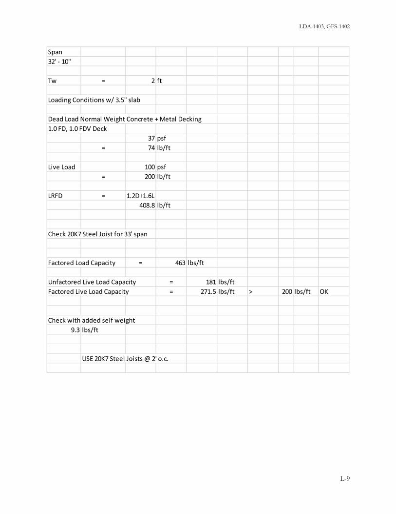
LDA-1403, GFS-1402
Span 32' - 10"
Tw = 2 ft
Loading Conditions w/ 3.5" slab
Dead Load Normal Weight Concrete + Metal Decking1.0 FD, 1.0 FDV Deck
37 psf= 74 lb/ft
Live Load 100 psf= 200 lb/ft
LRFD = 1.2D+1.6L408.8 lb/ft
Check 20K7 Steel Joist for 33' span
Factored Load Capacity = 463 lbs/ft
Unfactored Live Load Capacity = 181 lbs/ftFactored Live Load Capacity = 271.5 lbs/ft > 200 lbs/ft OK
Check with added self weight9.3 lbs/ft
USE 20K7 Steel Joists @ 2' o.c.
L-9

LDA-1403, GFS-1402
L-10

LDA-1403, GFS-1402
Span 32' - 10"
Tw = 3.1 ft 0.0833
Loading Conditions w/ 3.5" slab
Dead Load Normal Weight Concrete + Metal Decking1.0 FD, 1.0 FDV Deck
= 37 psf114.1 lb/ft
Live Load 100 psf= 308.3 lb/ft
LRFD = 1.2D+1.6L630.2 lb/ft
Check Steel Joist 20K10 for 33' span
Factored Load Capacity including self weight = 660 lbs/ft
Unfactored Live Load Capacity = 251 lbs/ftFactored Live Load Capacity = 376.5 lbs/ft > 308.3 lbs/ft OK
weight of joist12.2 lbs/ft
L-11

LDA-1403, GFS-1402
L-12

LDA-1403, GFS-1402
Span 32' - 10"
Tw = 4.0 ft 0.0833
Loading Conditions w/ 3.5" slab
Dead Load Normal Weight Concrete + Metal Decking1.0 FD, 1.0 FDV Deck
= 37 psf148.0 lb/ft
Live Load 100 psf= 400.0 lb/ft
LRFD = 1.2D+1.6L817.6 lb/ft
Check Steel Joist 24LH06 for 33' span
Factored Load Capacity including self weight = 906 lbs/ft
Unfactored Live Load Capacity = 411 lbs/ftFactored Live Load Capacity = 616.5 lbs/ft > 400.0 lbs/ft OK
weight of joist16 lbs/ft
L-13

LDA-1403, GFS-1402
L-14

LDA-1403, GFS-1402
Dimensions of pool area32'-10" X 67'-4"
20K10 Joist @ 3.1 ft o.c.
# of Joists Needed
Pool Length/spacing = 21.7use 22
Total weight of joists
# of joists * self weight for 33' span = 8857.2 lbs12.2 lbs/ft
24LH06 Joist @ 4ft o.c.
# of Joists Needed
Pool Length/spacing = 16.8use 17
Total weight of joists
# of joists * self weight for 33' span = 8976 lbs16 lbs/ft
20K7 @ 2 ft o.c.
# of Joists Needed
Pool Length/spacing = 33.7use 34
Total weight of joists
# of joists * self weight for 33' span = 10434.6 lbs9.3 lbs/ft
L-15

LDA-1403, GFS-1402
Design Summary
Web Joists Concrete Slab Thickness Metal Decking Joist Spacing (ft) Total Factored Load Weight of Steel (lbs)
20K7 3 - 1/2 in. 1.0 FD, 1.0 FDV Deck 2 408.8 10434.620K10 3 - 1/2 in. 1.0 FD, 1.0 FDV Deck 3.1 630.2 8857.224LH06 3 - 1/2 in. 1.0 FD, 1.0 FDV Deck 4 817.6 8976
least weight solution
L-16

LDA-1403, GFS -1402
Appendix M – Cost Breakdown
Section Cost Demolition 2,363,374.00$ Square Foot 3,611,285.52$ Structural Assemblies 172,155.71$ Site 607,699.42$ Total Construction Cost 6,754,514.65$
Liability Insurance for One year is .24% of Construction Cost 16,437.18$ Permits $11 Per $1000 of Construction Cost 75,337.08$ 10% Design Cost 684,882.57$ 10% Overhead 684,882.57$ 10% Profit 684,882.57$ Location Factor 1.1
Alumni Gym Total Cost of Completion 9,791,030.28$
Site/ Logistics S.F Cost S.F Unit Cost Units Total costSignage 1.25" Letters, 12" Long (NCE 321) 5.79$ 20 115.80$ Temporary Power (NCE 322) 2.22$ 34.255 76.05$ Portable Toilets Deluxe per month (NCE 322) 120.00$ 12 1,440.00$ Hydraulic Truck Canes 80 Ton per Hour (NCE 322) 334.00$ 1600 534,400.00$ Self- Powered Boom-Lift 31'-40' per month (NCE 327) 1,780.00$ 10 17,800.00$ Scaffolding Rental 21' Wide with Base Plates per month (NCE 332) 179.00$ 8 1,432.00$ Temporary Shoring 500SF per Month (NCE 332) 287.00$ 3 861.00$ Chain Link Fence 501 to 701 Feet (NCE 334) 1.86$ 14000 26,040.00$ 6'x 24' Gates (NCE 334) 321.00$ 6 1,926.00$ Cleanup (NCE 335) 7.17 34.225 245.39$ Temporary Utilities (BBC 16) 36 34.255 1,233.18$ Fall Protection Equipment (BBC 18) 3.26 5000 16,300.00$ Personnal Protective Equipment (BBC 17) 290 20 5,800.00$ Total 607,669.42$
M-1
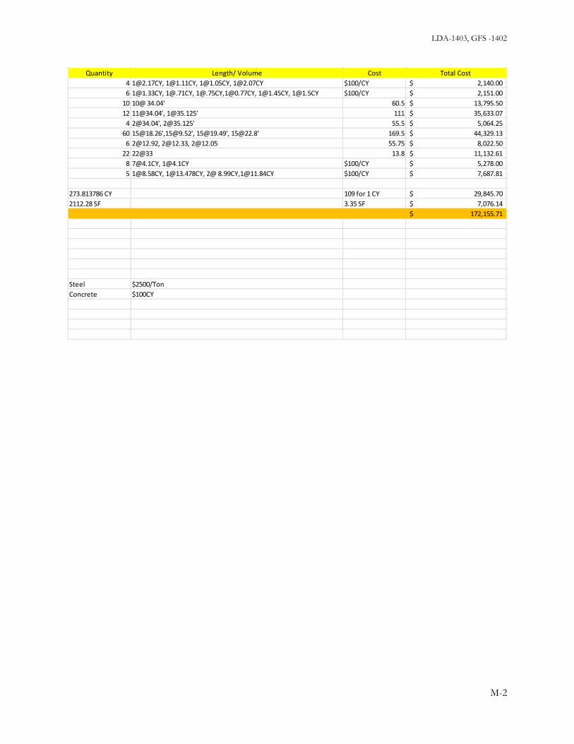
LDA-1403, GFS -1402
Quantity Length/ Volume Cost Total Cost 4 [email protected], [email protected], [email protected], [email protected] $100/CY 2,140.00$ 6 [email protected], [email protected], [email protected],[email protected], [email protected], [email protected] $100/CY 2,151.00$
10 10@ 34.04' 60.5 13,795.50$ 12 [email protected]', [email protected]' 111 35,633.07$
4 [email protected]', [email protected]' 55.5 5,064.25$ 60 [email protected]',[email protected]', [email protected]', [email protected]' 169.5 44,329.13$
6 [email protected], [email protected], [email protected] 55.75 8,022.50$ 22 22@33 13.8 11,132.61$
8 [email protected], [email protected] $100/CY 5,278.00$ 5 [email protected], [email protected], 2@ 8.99CY,[email protected] $100/CY 7,687.81$
273.813786 CY 109 for 1 CY 29,845.70$ 2112.28 SF 3.35 SF 7,076.14$
172,155.71$
Steel $2500/TonConcrete $100CY
M-2

LDA-1403, GFS-1402
RS Means 2013 Square Foot Costs (pg 102-103)College, Classroom, 2-3 StoryItem S.F Cost S.F Unit Cost Units Total costElevators 38,750 each 38,750.00$ Total 38,750.00$
HVAC 19 34,255 650,845.00$ Total 650,845.00$ Electrical Electrical Service 4.58 34255 156,887.90$ Lighting and Wiring 12.59 34255 431,270.45$ Communications 6.77 34255 231,906.35$ E. Generator 0.68 34255 23,293.40$ Total 843,358.10$ Interiors Partitions 7.23 34255 247,663.65$ Interior Doors 5.27 34255 180,523.85$ Fittings 4.76 34255 163,053.80$ Stair Construction 5 34255 171,275.00$ Wall Finishes 3.74 34255 128,113.70$ Floor Finishes 4.86 34255 166,479.30$ Ceiling Finishes 6.57 34255 225,055.35$ Total 1,282,164.65$ Plumbing Plumbing Fixtures 15.67 34255 536,775.85$ Oil fired Hot Water Heater 2.25 34255 77,073.75$ Roof Drains 0.59 34255 20,210.45$ Total 634,060.05$ Fire Protection Sprinklers 3 34255 102,765.00$ Standpipes 0.3 34255 10,276.50$ TotalStone Refurbishing Cut and Repoint Brick 7.4 5534.57 40,955.82$ Total 40,955.82$ Roofing Roof Coverings 2.74 2960 8,110.40$ Roof Total 8,110.40$
M-3

LDA-1403, GFS-1402
Demolition S.F Cost S.F Unit Cos Units Total costMasonry Building (pp338 2014 National Construction Estimator) 4.52 34255 164,832.60$ Plaster Walls (pp104 2014 National Construction Estimator) 0.44 34255 15,072.20$ Carpet (pp 101 National Construction Estimator) 7.38 755 5,571.90$ Concrete Slab Reinforced Removal (BBC pg 32) 29 2400 69,600.00$ Casework Demo Gutting (BBC 344) 7.2 34255 246,636.00$ Roof Demo (pp 338NCE) 114 2960 337,440.00$ Ceiling Demo (pp339 NCE) 0.98 34255 33,569.90$ Access Holes (pp340 NCE) 3.68 10 36.80$ Asbestos Surveying (341 NCE) 90 8 720.00$ Asbestos Removal (342 NCE) 70.9 5000 354,500.00$ Dumpter Rental 30 C.Y. Capacity (33 BBC) 890 12 10,680.00$ Debris Removal (Wheelbarrow) (340 NCE) 19.17 15000 287,550.00$ Debris Removal (Trash Chutes) (340 NCE) 25.38 15000 380,700.00$ Remove Framing (33 BBC) 353.7 1000 353,700.00$ Total 2,260,609.40$
M-4
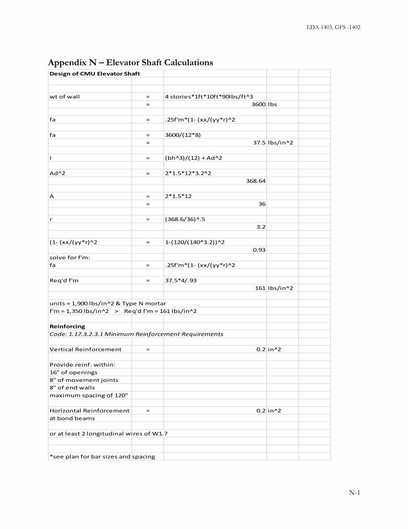
LDA-1403, GFS -1402
Appendix N – Elevator Shaft Calculations
Design of CMU Elevator Shaft
wt of wall = 4 stories*1ft*10ft*90lbs/ft^3= 3600 lbs
fa = .25f'm*(1- (xx/(yy*r)^2
fa = 3600/(12*8)= 37.5 lbs/in^2
I = (bh^3)/(12) + Ad^2
Ad^2 = 2*1.5*12*3.2^2368.64
A = 2*1.5*12= 36
r = (368.6/36)^.53.2
(1- (xx/(yy*r)^2 = 1-(120/(140*3.2))^20.93
solve for f'm:fa = .25f'm*(1- (xx/(yy*r)^2
Req'd f'm = 37.5*4/.93161 lbs/in^2
units = 1,900 lbs/in^2 & Type N mortarf'm = 1,350 lbs/in^2 > Req'd f'm = 161 lbs/in^2
ReinforcingCode: 1.17.3.2.3.1 Minimum Reinforcement Requirements
Vertical Reinforcement = 0.2 in^2
Provide reinf. within:16" of openings8" of movement joints8" of end wallsmaximum spacing of 120"
Horizontal Reinforcement = 0.2 in^2at bond beams
or at least 2 longitudinal wires of W1.7
*see plan for bar sizes and spacing
N-1

LDA-1403, GFS-1402
Appendix O - List of E-Files Analysis
Truss
Truss Analysis Summary
Truss Member Stresses Forces
Gravity Load Analysis
Level 4 framing – wood beams
Level 4 framing – steel girders
Framing Level 3
Wind Analysis
Building Wind
MECA Wind
Seismic Analysis
Seismic
Finite Element End Wall
MECA Seismic
Pool Slab
Pool Slab Design
Sources for pool slab
BIM Models
New Structural Model
Existing
Navisworks Model
Original Sources
Original Drawings – Alumni, 1914
Original Specs
O-1

LDA-1403, GFS-1402
Construction
Site Logistics
Site Plan
Primavera Schedule
Estimate
Photos
Alumni Tour #1
Site Tour
O-2