renovate preoperative care unit 438-19-101
TRANSCRIPT

RENOVATE PREOPERATIVE CARE UNIT 438-19-101 – BID SET 11/06/2020
08 71 0 - 1
SECTION 08 71 00
DOOR HARDWARE
GENERAL
1.1 CONDITIONS
A. Conditions of the contract (General and Supplementary Conditions) and Division One General Requirements, govern the work of this section.
B. This section includes all material, and related service necessary to furnish all finish hardware indicated on the drawings, or specified
herein.
C. Furnish UL listed hardware for all labeled and 20 min. openings in conformance with the requirements for the class of opening scheduled.
Underwriters' requirements shall have precedence over specification
where conflicts exist.
D. All work shall be in accordance with all applicable state and local building codes. Code requirements shall have precedence over this
specification where conflicts exist.
1.2 WORK INCLUDED
A. This section includes the following:
1. Furnish door hardware (for hollow metal, wood and aluminum doors) specified herein, listed in the hardware schedule, and/or required by
the drawings.
2. Electro-Mechanical Devices 3. Access Control components and or systems specified within this
section.
B. Where items of hardware are not definitely or correctly specified and is required for the intended service, such omission, error or other
discrepancy should be directed to the Architect prior to the bid date
for clarification by addendum. Otherwise furnish such items in the type
and quantity established by this specification for the appropriate
service intended.
1.3 RELATED WORK IN OTHER SECTIONS
A. This section includes coordination with related work in the following sections:
1. Division 6 Section "Finish Carpentry". 2. Division 6 Section "Cabinet Hardware". 3. Division 8 Section "Hollow Metal Doors and Frames". 4. Division 8 Section "Wood Doors". 5. Division 8 Section “Sliding Doors”. 6. Division 8 Section “Aluminum-Framed Entrances”. 7. Division 28 Sections "Electrical".
1.4 REFERENCES
A. Publications of agencies and organizations listed below form a part of this specification section to the extent referenced.
1. DHI - Recommended Locations for Builders' Hardware. 2. NFPA 80 - Standards for Fire Doors and Windows. 3. NFPA 101 - Code for Safety to Life from Fire in Buildings and
Structures.
4. UL - Building Material Directory. 5. DHI - Door and Hardware Institute

RENOVATE PREOPERATIVE CARE UNIT 438-19-101 – BID SET 11/06/2020
08 71 0 - 2
6. WHI - Warnock Hersey 7. BHMA - Builders Hardware Manufacturers Association 8. ANSI – American National Standards Institute 9. IBC 2012 - International Building Code 2015 Edition (as amended by
local building code)
1.5 SUBMITTALS
A. Within ten days after award of contract, submit detailed hardware schedule in quantities as required by Division 1 - General Conditions.
B. Schedule format shall be consistent with recommendations for a vertical format as set forth in the Door & Hardware Institute's (DHI)
publication "Sequence and Format for the Hardware Schedule". Hardware
sets shall be consolidated to group multiple door openings which share
similar hardware requirements. Schedule shall include the following
information:
1. Door number, location, size, handing, and rating. 2. Door and frame material, handing. 3. Degree of swing. 4. Manufacturer 5. Product name and catalog number 6. Function, type and style 7. Size and finish of each item 8. Mounting heights 9. Explanation of abbreviations, symbols, etc. 10.Numerical door index, indicating the hardware set/ group number for
each door.
C. When universal type door closers are to be provided, the schedule shall indicate the application method to be used for installation at each
door: (regular arm, parallel arm, or top jamb).
D. The schedule will be prepared under the direct supervision of a certified Architectural Hardware Consultant (AHC) employed by the
hardware distributor. The hardware schedule shall be signed and
embossed with the DHI certification seal of the supervising AHC. The
supervising AHC shall attend any meetings related to the project when
requested by the architect.
E. Check the specified hardware for suitability and adaptability to the details and surrounding conditions.
F. Review drawings from related trades as required to verify compatibility with specified hardware. Indicate unsuitable or in compatible items,
and proposed substitutions in the hardware schedule.
G. Provide documentation for all hardware to be furnished on labeled fire doors indicating compliance with positive pressure fire testing UL 10C.
H. Furnish manufacturers' catalog data for each item of hardware in quantities as required by Division 1 - General Conditions.
I. Submit a sample of each type of hardware requested by the architect. Samples shall be of the same finish, style, and function as specified
herein. Tag each sample with its permanent location so that it may be
used in the final work.
J. Furnish with first submittal, a list of required lead times for all hardware items.

RENOVATE PREOPERATIVE CARE UNIT 438-19-101 – BID SET 11/06/2020
08 71 0 - 3
K. After final approved schedule is returned, transmit corrected copies for distribution and field use in quantities as required by Division 1
- General Conditions.
L. Furnish approved hardware schedules, template lists, and pertinent templates as requested by related trades.
M. Furnish necessary diagrams, schematics, voltage and amperage requirements for all electro-mechanical devices or systems as required
by related trades. Wiring diagrams shall be opening specific and
include both a riser diagram and point to point diagram showing all
wiring terminations.
N. After receipt of approved hardware schedule, Hardware supplier shall initiate a meeting including the owner's representative to determine
keying requirements. Upon completion of the initial key meeting,
hardware supplier shall prepare a proposed key schedule with symbols
and abbreviations as set forth in the door and hardware institute's
publication "Keying Procedures, Systems, and Nomenclature". Submit
copies of owner approved key schedule for review and field use in
quantities as required by Division 1 - General Conditions. Wiring
diagrams shall be included in final submittals transmitted for
distribution and field use.
1.6 QUALITY ASSURANCE
A. Manufacturers and model numbers listed are to establish a standard of function and quality. Similar items by approved manufacturers that are
equal in design, function, and quality, may be considered for prior
approval of the architect, provided the required data and physical
samples are submitted for approval as set forth in Division One General
Requirements.
B. Where indicated in this specification, products shall be independently certified by ANSI for compliance with relevant ANSI/BHMA standards
A156.1 - A156.36 – Standards for Hardware and Specialties. All products
shall meet or exceed certification requirements for the respective
grade indicated within this specification. Supplier shall provide
evidence of certification when requested by the architect.
C. Obtain each type of hardware (hinges, latch & locksets, exit devices, closers, etc.) from a single manufacturer, although several may be
indicated as offering products complying with requirements.
D. Electrical drawings and electrical specifications are based on the specific electrified hardware components specified in hardware sets.
When electronic hardware components other than those indicated in
hardware sets are provided, the supplier shall be responsible for all
costs incurred by the design team and their consultants to review and
revise electrical drawings and electrical specifications. Supplier
shall also be responsible for any additional costs associated with
required changes in related equipment, materials, installation, or
final hook up to insure the system will operate and function as
indicated in the construction documents, including hardware set
operational / functional descriptions.
E. All hardware items shall be manufactured no earlier than 6 months prior to delivery to site.

RENOVATE PREOPERATIVE CARE UNIT 438-19-101 – BID SET 11/06/2020
08 71 0 - 4
F. Hardware supplier shall be factory trained and certified by the manufacture to provide and support all computer managed locks and
system components.
G. Installation of hardware shall be installed or directly supervised and inspected by a skilled installer certified by the manufacturer of
locksets, door closers, and exit devices used on the project, or with
not less than 3 years’ experience in successful completion of projects
similar in size and scope.
H. Provide hardware for all labeled fire doors, which complies with positive pressure fire testing UL 10C.
I. Comply with all applicable provisions of the standards referenced within section 1.4 of this specification.
J. Hardware supplier shall participate when reasonably requested to meet with the contractor and or architect to inspect any claim for incorrect
or non-functioning materials; following such inspection, the hardware
supplier shall provide a written statement documenting the cause and
proposed remedy of any unresolved items.
1.7 DELIVERY, STORAGE AND HANDLING
A. Hardware supplier shall deliver hardware to the job site unless otherwise specified.
B. All hardware shall be delivered in manufacturers' original cartons and shall be clearly marked with set and door number.
C. Coordinate with contractor prior to hardware delivery and recommend secure storage and protection against loss and damage at job site.
D. Contractor shall receive all hardware and provide secure and proper protection of all hardware items to avoid delays caused by lost or
damaged hardware. Contractor shall report shortages to the Architect
and hardware supplier immediately after receipt of material at the job
site.
E. Coordinate with related trades under the direction of the contractor for delivery of hardware items necessary for factory installation.
1.8 PRE-INSTALLATION MEETING
A. Schedule a hardware pre-installation meeting on site to review and discuss the installation of continuous hinges, locksets, door closers,
exit devices, overhead stops, and electromechanical door hardware.
B. Meeting attendees shall be notified 7 days in advance and shall include: Architect, Contractor, Door Hardware Installers (including low
voltage hardware), Manufacturers representatives for above hardware
items, and any other effected subcontractors or suppliers.
C. All attendees shall be prepared to distribute installation manuals, hardware schedules, templates, and physical hardware samples.
1.9 WARRANTY
A. All hardware items shall be warranted against defects in material and workmanship as set forth in Division One General Requirements.
B. Repair, replace, or otherwise correct deficient materials and workmanship without additional cost to owner.
RENOVATE PREOPERATIVE CARE UNIT 438-19-101 – BID SET 11/06/2020
08 71 0 - 5
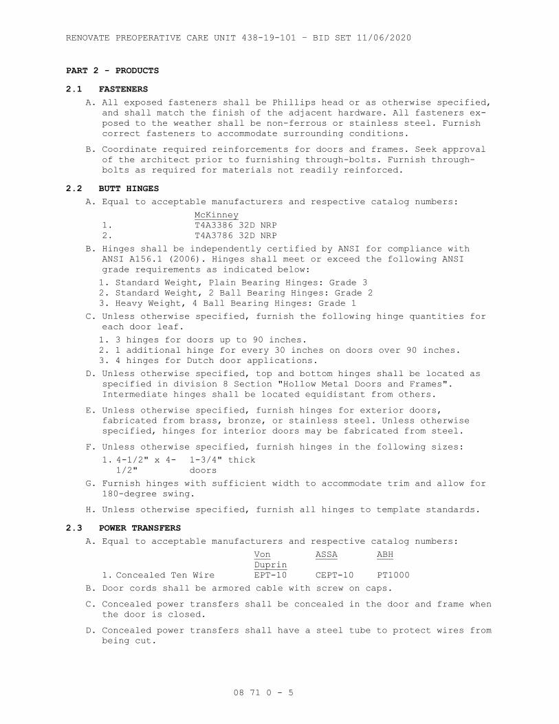
PART 2 - PRODUCTS
2.1 FASTENERS
A. All exposed fasteners shall be Phillips head or as otherwise specified, and shall match the finish of the adjacent hardware. All fasteners ex-
posed to the weather shall be non-ferrous or stainless steel. Furnish
correct fasteners to accommodate surrounding conditions.
B. Coordinate required reinforcements for doors and frames. Seek approval of the architect prior to furnishing through-bolts. Furnish through-
bolts as required for materials not readily reinforced.
2.2 BUTT HINGES
A. Equal to acceptable manufacturers and respective catalog numbers:
McKinney
1. T4A3386 32D NRP
2. T4A3786 32D NRP
B. Hinges shall be independently certified by ANSI for compliance with ANSI A156.1 (2006). Hinges shall meet or exceed the following ANSI
grade requirements as indicated below:
1. Standard Weight, Plain Bearing Hinges: Grade 3 2. Standard Weight, 2 Ball Bearing Hinges: Grade 2 3. Heavy Weight, 4 Ball Bearing Hinges: Grade 1
C. Unless otherwise specified, furnish the following hinge quantities for each door leaf.
1. 3 hinges for doors up to 90 inches. 2. 1 additional hinge for every 30 inches on doors over 90 inches. 3. 4 hinges for Dutch door applications.
D. Unless otherwise specified, top and bottom hinges shall be located as specified in division 8 Section "Hollow Metal Doors and Frames".
Intermediate hinges shall be located equidistant from others.
E. Unless otherwise specified, furnish hinges for exterior doors, fabricated from brass, bronze, or stainless steel. Unless otherwise
specified, hinges for interior doors may be fabricated from steel.
F. Unless otherwise specified, furnish hinges in the following sizes:
1. 4-1/2" x 4-1/2"
1-3/4" thick
doors
G. Furnish hinges with sufficient width to accommodate trim and allow for 180-degree swing.
H. Unless otherwise specified, furnish all hinges to template standards.
2.3 POWER TRANSFERS
A. Equal to acceptable manufacturers and respective catalog numbers:
Von
Duprin
ASSA ABH
1. Concealed Ten Wire EPT-10 CEPT-10 PT1000
B. Door cords shall be armored cable with screw on caps.
C. Concealed power transfers shall be concealed in the door and frame when the door is closed.
D. Concealed power transfers shall have a steel tube to protect wires from being cut.

RENOVATE PREOPERATIVE CARE UNIT 438-19-101 – BID SET 11/06/2020
08 71 0 - 6
E. Concealed power transfers with spring tubes shall be rejected.
F. Concealed power transfers shall be supplied with a mud box to house all terminations.
2.4 FLUSH BOLTS AND DUST PROOF STRIKES
A. Equal to acceptable manufacturers and respective catalog numbers:
Ives Door
Controls
Hager
1. Dust Proof Strike DP2 80 280X
2. Auto Flush Bolt (Metal Door) FB31P 842 292D
3. Auto Flush Bolt (Wood Door) FB41P 942 291D
4. Constant Latching Bolt (Metal Door)
FB51P 845 293D
5. Constant Latching Bolt (Wood Door)
FB61P 945 294D
6. Manual Flush Bolt FB458 780 282D
B. Unless otherwise specified, provide 12" rods for manual flush bolts for door 7'6" or less, 24" top rods for doors over 7'6" to 8'6".
C. Unless otherwise specified, provide doors over 8'6" with automatic top bolts.
D. Provide automatic flush bolts where required to maintain fire door listing and or egress requirements on pairs of doors.
E. All flush-bolt applications shall be UL listed to be installed with top flush-bolt only. Provide auxiliary fire bolt as required for fire rated
openings where less bottom bolt has been specified.
F. Provide all bottom flush bolts with non-locking dust proof strikes.
2.5 EXIT DEVICES
A. Equal to acceptable manufacturers and respective catalog numbers:
Von Duprin
1. Wide Stile, Push Pad 99 Series
2. Wide Stile, Electric Latch Retraction
QEL 99
Series
3. Lever Trim 996 Series
4. Pull Trim 990 Series
B. Exit devices shall be independently certified by ANSI for compliance with ANSI A156.3, Grade 1 (2008).
C. Obtain exit devices from a single manufacturer, although several may be indicated as offering products complying with requirements.
D. All exit devices shall be equipped with a sound-dampening feature to reduce touch pad return noise.
E. Quiet Electric Latch Retraction shall be accomplished using a motor driven assembly, and shall incorporate the following features:
1. Motor shall retract both the push pad assembly and latchbolt. 2. Automatic calibration of latch throw and pull. 3. Built-in time delay. 4. On-board installation and troubleshooting diagnostics built into
power supply and device.
5. Retry mode if device does not pull on the first try.
F. On full glass doors there shall be no exposed fasteners on the back of the mechanism visible through the glass.

RENOVATE PREOPERATIVE CARE UNIT 438-19-101 – BID SET 11/06/2020
08 71 0 - 7
G. All exit devices shall be provided with flush end caps to reduce potential damage from impact.
H. All exit devices shall be provided with dead-locking latch bolts to ensure security.
I. All exit devices shall be U.L. listed for accident hazard. Exit device for use on fire doors shall also be U.L. listed for fire exit hardware.
J. Provide optional strikes, special length rods, and adapter plates to accommodate door and frame conditions. Provide narrow style series
devices in lieu of wide stile series devices where optional strikes
will not accommodate door and frame conditions.
K. Coordinate with related trades to ensure adequate clearance and reinforcement is provided in doors and frames. Provide thru bolts as
required.
L. Refer to hardware groups for exit device applications utilizing the option of: "less bottom rod and floor strike" (LBR)
M. All exit devices shall be provided with optional trim designs to match other lever and pull designs used on the project.
N. Unless specific exit device dogging options are noted within hardware sets, provide dogging options as follows:
1. Fire Rated devices: Dogging not permitted. 2. Non-Rated Exit Only functions not equipped with outside trim or pull:
Less Dogging.
3. Non-Rated Classroom functions: Less Dogging. 4. Non-Rated devices utilizing electric latch retraction or electrified
outside trim: Less Dogging.
5. All Other Non-Rated devices: Cylinder Dogging utilizing interchangeable core cylinders. Cylinder keyway shall match locksets
furnished on this project.
O. Provide glass bead kits as required to accommodate door conditions. Screws shall not be visible through full glass doors.
P. Where specified, provide compatible keyed mullions with cylinder for pairs of doors.
Q. Provide reinforced crossbars for all traditional style exit devices applied to doors over 36" wide.
2.6 LOCKS AND LATCHES
A. Equal to acceptable manufacturers and respective catalog numbers:
LSDA
1. Grade 1 Cylindrical
LF2000 Series
(LE)
B. Bored locks shall be independently certified by ANSI for compliance with ANSI A156.2 (2011).
C. Unless otherwise specified, all locks and latches to have:
1. 2-3/4" Backset 2. 1/2" minimum throw latchbolt 3. 1" throw deadbolt 4. ANSI A115.2 strikes
D. Provide guarded latch bolts for all locksets, and latch bolts with sufficient throw to maintain fire rating of both single and paired door
assemblies.

RENOVATE PREOPERATIVE CARE UNIT 438-19-101 – BID SET 11/06/2020
08 71 0 - 8
E. Length of strike lip shall be sufficient to clear surrounding trim.
F. Provide wrought boxes for strikes at inactive doors, wood frames, and metal frames without integral mortar covers.
2.7 CLOSERS
A. Equal to acceptable manufacturers and respective catalog numbers:
LCN
1. 1460 REG / EDA
2. 4040XP / 4040XP EDA
B. Door closers shall be independently certified by ANSI for compliance with ANSI A156.4, Grade 1 (2013).
C. Obtain door closers from a single manufacturer, although several may be indicated as offering products complying with requirements.
D. Provide extra heavy-duty arm (EDA / HD) when closer is to be installed using parallel arm mounting.
E. Closers shall use high strength cast iron cylinders, forged main arms, and 1-piece forged steel pistons.
F. Closers shall utilize a stable fluid withstanding temperature range of +120deg F to -30deg F without seasonal adjustment of closer speed to
properly close the door. Closers for fire-rated doors shall be provided
with temperature stabilizing fluid that complies with standards UL10C.
G. Unless otherwise specified, all door closers shall have full covers and separate adjusting valves for sweeps, latch, and backcheck.
H. Provide closers for all labeled doors. Provide closer series and type consistent with other closers for similar doors specified elsewhere on
the project.
I. Provide closers with adjustable spring power. Size closers to insure exterior and fire rated doors will consistently close and latch doors
under existing conditions. Size all other door closers to allow for
reduced opening force not to exceed 5 lbs.
J. Install closers on the room side of corridor doors, stair side of stairways and interior side of exterior doors.
K. Closers shall be furnished complete with all mounting brackets and cover plates as required by door and frame conditions, and by adjacent
hardware.
L. Door closers shall be provided with a powder coat finish to provide superior protection against the effects of weathering. Powder coat
finish shall successfully pass a (100-hour salt spray test)
M. Pressure Relief Valve, PRV, shall not be acceptable.
2.8 KICK PLATES AND MOP PLATES
A. Furnish protective plates as specified in hardware groups.
B. Where specified, provide 10" kick plates, 34" armor plates, and 4" mop plates. Unless otherwise specified, metal protective plates shall be
.050" thick; plastic plates shall be 1/8" thick.
C. Protective plates shall be 2" less door width, or 1" less door width at pairs. All protective plates shall be beveled 4 sides and counter sunk.

RENOVATE PREOPERATIVE CARE UNIT 438-19-101 – BID SET 11/06/2020
08 71 0 - 9
Protection plates over 16" shall not be provided for labeled doors
unless specifically approved by door manufacturers listing.
D. Where specified, provide surface mounted door edges. Edges shall butt to protective plates. Provide edges with cutouts as required adjacent
hardware.
E. Adjust dimensions of protection plates to accommodate stile and rail dimensions, lite and louver cutouts, and adjacent hardware. Where
required by adjacent hardware, protection plates shall be factory
drilled for cylinders or other mortised hardware.
2.9 OVERHEAD STOPS
A. Equal to acceptable manufacturers and respective catalog numbers:
Glynn-
Johnson Rixson
Sargen
t
1. Heavy Duty Surface Mount GJ900 Series 9
Series
590
2. Heavy Duty Concealed Mount
GJ100 Series 1
Series
690
B. Unless otherwise specified, furnish GJ900 series overhead stop for hollow metal or 1-3/4” solid core doors equipped with regular arm
surface type closers that swing more than 140 degrees before striking a
wall, for hollow metal or 1-3/4” solid core doors that open against
equipment, casework, sidelights, or other objects that would make wall
bumpers inappropriate, and as specified in hardware groups.
C. Furnish hex bolt attachments for wood and mineral core doors unless doors are supplied with proper reinforcing blocks.
D. Do not provide holder function for labeled doors.
2.10 WALL STOPS AND HOLDERS
A. Equal to acceptable manufacturers and respective catalog numbers:
Ives Hager Burns
1. Wrought Convex Wall Bumper
WS406CVX 232W 570
2. Wrought Concave Wall Bumper
WS406CCV 236W 575
B. Furnish a stop or holder for all doors. Furnish floor stops or hinge pin stops only where specifically specified.
C. Where wall stops are not applicable, furnish overhead stops.
D. Do not provide holder function for labeled doors.
2.11 WEATHERSTRIP, GASKETING
A. Equal to acceptable manufacturers and respective catalog numbers:
Zero Pemko NGP Reese
1. Adhesive Gasket 188 S88 5050 797
B. Weatherstrip and gasketing shall be independently certified by ANSI for compliance with ANSI A156.22 (2005).
C. Where specified in the hardware groups, furnish the above products unless otherwise detailed in groups.
D. Provide weatherstripping all exterior doors and where specified.

RENOVATE PREOPERATIVE CARE UNIT 438-19-101 – BID SET 11/06/2020
08 71 0 - 10
E. Provide intumescent and other required edge sealing systems as required by individual fire door listings to comply with positive pressure
standards UL 10C.
F. Provide Zero 188 smoke gaskets at all fire rated doors and smoke and draft control assemblies.
G. Provide gasketing for all meeting edges on pairs of fire doors. Gasketing shall be compatible with astragal design provided by door
supplier as required for specific fire door listings.
2.12 ELECTRIC STRIKES
A. Equal to acceptable manufacturers and respective catalog numbers:
Von
Duprin
Folger
Adams
1. Type 1 6000
Series
300 Series
B. Provide electric strikes designed for use with the type of locks shown at each opening where specified.
C. Electric strikes shall be UL listed as Burglary-Resistant Electric Door Strikes and where required shall be UL listed as Electric Strike for
Fire Doors.
D. Provide transformers and rectifiers for each strike as required. Verify voltage with electrical contractor.
2.13 MAGNETIC LOCKS
A. Equal to acceptable manufacturers and respective catalog numbers:
Schlage
Electronics
Securit
ron
1. Direct Hold
M490 Series 82B
B. Provide magnetic locks as specified, complete with mounting brackets and fasteners appropriate to the application. Direct Hold magnetic
locks shall have a minimum of 1500 lbs. holding force.
C. Provide magnetic locks with integral magnetic bond sensor, time delay (1-90 Seconds) for re-locking, and LED status indicator as noted in
hardware groups.
D. Provide regulated and filtered power supplies for magnetic locks by the same manufacturer.
2.14 POWER SUPPLIES
A. Provide quantities and types as specified in hardware sets. Shared power supplies will not be accepted without prior approval from the
owner.
B. All power supplies shall have the following features:
1. 12/24 VDC Output, field selectable. 2. Class 2 Rated power limited output. 3. Universal 120-240 VAC input. 4. Low voltage DC, regulated and filtered. 5. Polarized connector for distribution boards. 6. Fused primary input. 7. AC input and DC output monitoring circuit w/LED indicators. 8. Cover mounted AC Input indication.

RENOVATE PREOPERATIVE CARE UNIT 438-19-101 – BID SET 11/06/2020
08 71 0 - 11
9. Tested and certified to meet UL294. 10. NEMA 1 enclosure.
11. Hinged cover w/lock down screws.
12. High voltage protective cover.
C. All power supplies shall incorporate fused distribution boards.
D. All electro-mechanical systems requiring fail safe circuits shall be capable of interfacing with the fire alarm system to cut power to
appropriate system components. Unless already provided in another
system component, all power supplies utilized in fail safe circuits
shall include an integral relay which when connected to the N/C fire
alarm contact will cut power to all openings connected to the
individual power supply. Power supply, unless otherwise specified, will
automatically reset itself when fire alarm relay returns to normal
state following a fire alarm.
2.15 DOOR POSITION SWITCHES
A. Equal to acceptable manufacturers and respective catalog numbers:
Schlage
Electronics
Sentrol Sarge
nt
1. Concealed (wood & hollow metal doors)
679 Series 1076W 3287
2.16 MANUALLY PROGRAMMED LOCKS
A. Equal to acceptable manufacturers and respective catalog numbers:
Simplex No Substitution
1. Cylindrical Lockset
L1000 Series
B. Provide locks with mechanical key override.
C. Provide cylinders as required
D. Lever trim shall match locksets when available.
E. Bored locks shall be independently certified by ANSI for compliance with ANSI A156.2, Grade 1 (2011). Mortise locks shall be independently
certified by ANSI for compliance with ANSI A156.13, Grade 1 (2012).
F. Lockset shall be listed and certified for compliance with UL 294.
G. Keypad operation
H. Hardware supplier shall be factory trained and certified by the manufacture to provide and support all computer managed locks and
system components.
I. Hardware supplier shall provide onsite training to the end user as required by the manufacturer.
2.17 FINISHES AND BASE MATERIALS
A. Unless otherwise indicated in the hardware groups or herein, hardware finishes shall be applied over base metals as specified in the
following finish schedule:
HARDWARE ITEM BHMA FINISH AND BASE MATERIAL
1. Butt Hinges: Exterior, or Non-Ferrous
630 (US32D - Satin Stainless
Steel)
2. Butt Hinges: Interior 652 (US26D - Satin Chromium)
3. Continuous Hinges 630 (US32D - Satin Stainless

RENOVATE PREOPERATIVE CARE UNIT 438-19-101 – BID SET 11/06/2020
08 71 0 - 12
Steel)
4. Exit Devices 626 (US26D - Satin Chromium)
5. Locks and Latches 626 (US26D - Satin Chromium)
6. Pulls and Push Plates/Bars
630 (US32D - Satin Stainless
Steel)
7. Closers 689 (Powder Coat Aluminum)
8. Protective Plates 630 (US32D - Satin Stainless
Steel)
9. Overhead Stops 630 (US32D - Satin Stainless
Steel)
10. Wall Stops and Holders 630 (US32D - Satin Stainless
Steel)
11. Thresholds 628 (Mill Aluminum)
12. Weather-strip, Sweeps Drip
Caps (wood and hollow metal
doors)
Aluminum Anodized
13. Weather-strip, Sweeps Drip
Caps (aluminum doors)
Match finish of aluminum doors.
14. Miscellaneous 626 (US26D - Satin Chromium)
2.18 KEYING
A. Provide all cylinders in keyways as required to accommodate owners existing Falcon Great Grand Master Key System.
B. Provide interchangeable cores for all locks and cylinders.
C. All locks under this section shall be keyed as directed by the owner to an existing Master Key System.
D. Furnish a total of 2 keys per cylinder. Actual cut keys to be determined by owner.
E. Master keys, control keys, and change keys shall be delivered by registered mail to the owner. Construction keys shall be delivered to
the contractor.
F. Cylinders shall be 6 pin “D” keyway, uncombinated standard cores.
PART 3 - EXECUTION
3.1 EXAMINATION
A. Prior to installation of hardware, installer shall examine door frame installation to ensure frames have been set square and plumb. Installer
shall examine doors, door frames, and adjacent wall, floor, and ceiling
for conditions, which would adversely affect proper operation and
function of door assemblies. Do not proceed with hardware installation
until such deficiencies have been corrected.
3.2 INSTALLATION
A. Before hardware installation, general contractor/construction manager shall coordinate a hardware installation seminar with a 1 week notice
to all parties involved. The seminar is to be conducted on the
installation of hardware, specifically of locksets, closers, exit
devices, continuous hinges and overhead stops. Manufacturer's
representative of the above products to present seminar. Seminar to be
held at the job site and attended by installers of hardware (including
low voltage hardware) for aluminum, hollow metal and wood doors.
Training to include use of installation manuals, hardware schedule,
templates and physical products samples.

RENOVATE PREOPERATIVE CARE UNIT 438-19-101 – BID SET 11/06/2020
08 71 0 - 13
B. Install all hardware in accordance with the approved hardware schedule and manufacturers instructions for installation and adjustment.
C. Set units level, plumb and true to the line and location. Adjust and reinforce the attachment substrate as necessary for proper installation
and operation.
D. Drill and countersink units which are not factory-prepared for anchorage fasteners. Space fasteners and anchors in accord with
industry standards.
E. Drill appropriate size pilot holes for all hardware attached to wood doors and frames.
F. Shim doors as required to maintain proper operating clearance between door and frame.
G. Unless otherwise specified, locate all hardware in accordance with the recommended locations for builder’s hardware for standard doors and
frames as published by the Door and Hardware Institute.
H. Use only fasteners supplied by or approved by the manufacturer for each respective item of hardware.
I. Mortise and cut to close tolerance and conceal evidence of cutting in the finished work.
J. Conceal push and pull bar fasteners where possible. Do not install through bolts through push plates.
K. Install hardware on UL labeled openings in accordance with manufacturer's requirements to maintain the label.
L. Apply self-adhesive gasketing on frame stop at head & latch side and on rabbet of frame at hinge side.
M. Install hardware in accordance with supplemental "S" label instructions on all fire rated openings.
N. Install wall stops to contact lever handles or pulls. Do not mount wall stops on casework, or equipment.
O. Where necessary, adjust doors and hardware as required to eliminate binding between strike and latchbolt. Doors should not rattle.
P. Overhead stops used in conjunction with electrified hold open closers shall be templated and installed to coincide with engagement of closer
hold open position.
Q. Install door closers on corridor side of lobby doors, room side of corridor doors, and stair side of stairways.
R. Adjust spring power of door closers to the minimum force required to insure exterior and fire rated doors will consistently close and latch
doors under existing conditions. Adjust all other door closers to
ensure opening force does not to exceed 5 lbs.
S. Adjust "sweep", "latch", & "back check" valves on all door closers to properly control door throughout the opening and closing cycle. Adjust
total closing speed as required to comply with all applicable state and
local building codes.
T. Install "hardware compatible" (bar stock) type weatherstripping continuously for an uninterrupted seal. Adjust templating for parallel

RENOVATE PREOPERATIVE CARE UNIT 438-19-101 – BID SET 11/06/2020
08 71 0 - 14
arm door closers, exit devices, etc., as required to accommodate
weatherstripping.
U. Unless otherwise specified or detailed, install thresholds with the bevel in vertical alignment with the outside door face. Notch and
closely fit thresholds to frame profile. Set thresholds in full bed of
sealant.
V. Compress sweep during installation as recommended by sweep manufacturer to facilitate a water-resistant seal.
W. Deliver to the owner 1 complete set of installation and adjustment instructions, and tools as furnished with the hardware.
3.3 FIELD QUALITY CONTROL
A. After installation has been completed, the hardware supplier and manufacturers representative for locksets, door closers, exit devices,
and overhead stops shall check the project and verify compliance with
installation instructions, adjustment of all hardware items, and proper
application according to the approved hardware schedule. Hardware
supplier shall submit a list of all hardware that has not been
installed correctly.
B. After installation has been completed, the hardware supplier and manufacturers representative shall meet with the owner to explain the
functions, uses, adjustment, and maintenance of each item of hardware.
Hardware supplier shall provide the owner with a copy of all wiring
diagrams. Wiring diagrams shall be opening specific and include both a
riser diagram and point to point diagram showing all wiring
terminations.
3.4 ADJUSTMENT AND CLEANING
A. At final completion, and when H.V.A.C. equipment is in operation, installer shall make final adjustments to and verify proper operation
of all door closers and other items of hardware. Lubricate moving parts
with type lubrication recommended by the manufacturer.
B. All hardware shall be left clean and in good operation. Hardware found to be disfigured, defective, or inoperative shall be repaired or
replaced.
3.5 HARDWARE SCHEDULE
A. The following schedule of hardware groups are intended to describe opening function. The hardware supplier is cautioned to refer to the
preamble of this specification for a complete description of all
materials and services to be furnished under this section.
HW SET: 00
ALL HARDWARE BY ACCORDION FOLDING PARTICIAT SUPPLIER
HW SET: 01
EA HINGES AS SPECIFIED MCK
1 EA PASSAGE SET F75 LOC
1 EA WALL STOP L22251 IVE
FUNCTION: (F75) PASSAGE LATCH
BOTH LEVERS ALWAYS UNLOCKED.

RENOVATE PREOPERATIVE CARE UNIT 438-19-101 – BID SET 11/06/2020
08 71 0 - 15
HW SET: 02
1 EA SLIDING DOOR EXAM SLIDE ADA-2 X DROP SEAL
By SECTION 08 34 00
ADS
THUMBTURN WITH INDICATOR AND LADDER PULL.
HW SET: 03
1 EA SLIDING DOOR EXAM SLIDE X PULLS
By SECTION 08 34 00
ADS
NONLATCHING WITH LADDER PULLS.
HW SET: 04
EA HINGES AS SPECIFIED MCK
1 EA PRIVACY LOCK F76 LOC
1 EA WALL STOP L22251 IVE
1 EA GASKETING R0E154 ZER
FUNCTION: (F76) BATH/BEDROOM PRIVACY LOCK
PUSH-BUTTON LOCKING. CAN BE OPENED FROM OUTSIDE WITH SMALL SCREWDRIVER. TURNING INSIDE
LEVER OR CLOSING DOOR RELEASES BUTTON.
HW SET: 05
EA HINGES AS SPECIFIED MCK
1 EA ENTRY LOCK F109 LOC
1 EA IC CYLINDER AS REQUIRED FAL
1 EA WALL STOP L22251 IVE
FUNCTION: (F109) OFFICE/ENTRANCE LOCK
TURN/PUSH-BUTTON LOCKING; PUSHING AND TURNING BUTTON LOCKS OUTSIDE LEVER, REQUIRING
USE OF KEY UNTIL BUTTON IS MANUALLY UNLOCKED. PUSH-BUTTON LOCKING; PUSHING BUTTON
LOCKS OUTSIDE LEVER UNTIL UNLOCKED BY KEY OR BY TURNING INSIDE LEVER.
HW SET: 06
EA HINGES AS SPECIFIED MCK
1 EA STOREROOM LOCK F86 LOC
1 EA IC CYLINDER AS REQUIRED FAL
1 EA OH STOP C52541 GLY
FUNCTION: (F86) STOREROOM LOCK
OUTSIDE LEVER FIXED. ENTRANCE BY KEY ONLY. INSIDE LEVER ALWAYS UNLOCKED.
HW SET: 07
EA HINGES AS SPECIFIED MCK
1 EA MANUAL FLUSH BOLT FB458 IVE
1 EA STOREROOM LOCK F86 LOC
1 EA IC CYLINDER AS REQUIRED FAL
2 EA WALL STOP L22251 IVE
FUNCTION: (F86) STOREROOM LOCK
OUTSIDE LEVER FIXED. ENTRANCE BY KEY ONLY. INSIDE LEVER ALWAYS UNLOCKED.

RENOVATE PREOPERATIVE CARE UNIT 438-19-101 – BID SET 11/06/2020
08 71 0 - 16
HW SET: 08
EA HINGES AS SPECIFIED MCK
1 EA STOREROOM LOCK F86 LOC
1 EA IC CYLINDER AS REQUIRED FAL
1 EA ELECTRIC STRIKE E09321 (FAIL SECURE) VON
1 EA SURFACE CLOSER C02011 LCN
1 EA KICKPLATE J102 .050 10" X 2" LDW IVE
1 EA WALL STOP L22251 IVE
1 EA CARD READER BY SECURITY SUPPLIER
1 EA DOOR CONTACT 679-05 SCE
1 EA POWER SUPPLY PS902 2RS VON
1 EA ELEVATION DRAWING
1 EA WIRE DIAGRAM POINT TO POINT
FUNCTION: (F86) STOREROOM LOCK
OUTSIDE LEVER FIXED. ENTRANCE BY KEY ONLY. INSIDE LEVER ALWAYS UNLOCKED.
PRESENTATION OF VALID CREDENTIAL MOMENTARILY ENERGIZES ELECTRIC STRIKE.
HW SET: 09
EA HINGES AS SPECIFIED MCK
1 EA CLASSROOM LOCK F84 LOC
1 EA IC CYLINDER AS REQUIRED FAL
1 EA ELECTRIC STRIKE E09321 (FAIL SECURE) VON
1 EA AUTO OPERATOR PUSH SIDE STA
2 EA ACTUATOR ROUND W/BLUE LOGO STA
1 EA KICKPLATE J102 .050 10" X 2" LDW IVE
1 EA WALL STOP L22251 IVE
1 EA CARD READER BY SECURITY SUPPLIER
1 EA DOOR CONTACT 679-05 SCE
1 EA POWER SUPPLY PS902 2RS VON
1 EA ELEVATION DRAWING
1 EA WIRE DIAGRAM POINT TO POINT
FUNCTION: (F84) CLASSROOM LOCK
OUTSIDE LEVER LOCKED AND UNLOCKED BY KEY. INSIDE LEVER ALWAYS UNLOCKED.
OUTSIDE ACTUATOR IS CONTROLLED BY THE ACCESS CONTROL SYSTEM OR THE EXTERIOR ON/OFF
SWITCH. THE INSIDE ACTUATOR IS ALWAYS ACTIVE TO ENERGIZE STRIKE AND OPEN DOOR.

RENOVATE PREOPERATIVE CARE UNIT 438-19-101 – BID SET 11/06/2020
08 71 0 - 17
HW SET: 10
EA HINGES AS SPECIFIED MCK
2 EA POWER TRANSFER EPT10 VON
1 EA ELEC PANIC HARDWARE QEL-9927-L-DT-LBR
TYPE 2 LBR
VON
1 EA ELEC PANIC HARDWARE QEL-9927-L-NL-LBR
TYPE 2 LBR
VON
1 EA JUNCTION BOX JB7
W/RELAYS AS REQD
VON
1 EA IC CYLINDER AS REQUIRED FAL
1 EA OH STOP C52541 GLY
1 EA AUTO OPERATOR PUSH SIDE / PUSH SIDE STA
2 EA ACTUATOR ROUND W/BLUE LOGO STA
2 EA KICKPLATE J102 .050 10" X 1" LDW IVE
2 EA WALL STOP L22251 IVE
1 EA CARD READER BY SECURITY SUPPLIER
2 EA DOOR CONTACT 679-05 SCE
1 EA POWER SUPPLY PS904 4RL VON
1 EA ELEVATION DRAWING
1 EA WIRE DIAGRAM POINT TO POINT
FUNCTION: ANSI 03 (NL) LATCHBOLT RETRACTED INSIDE BY EXIT DEVICE PUSH PAD AND OUTSIDE
BY KEY IN CYLINDER. DOOR LOCKS WHEN KEY IS REMOVED AND DOOR IS CLOSED.
FUNCTION: ANSI 02 (DT) LATCHBOLT RETRACTED INSIDE BY EXIT DEVICE PUSH PAD.
PRESENTATION OF VALID CREDENTIAL MOMENTARILY UNLOCKS DOOR.
ACTUATORS RETRACT LATCHES AND ACTIVATE AUTO OPERATOR TO OPEN THE DOOR LEAFS.
OUTSIDE ACTUATOR IS CONTROLLED BY THE ACCESS CONTROL SYSTEM. INSIDE ACTUATOR IS ALWAYS
ACTIVE.
HW SET: 11
EA HINGES AS SPECIFIED MCK
1 EA POWER TRANSFER EPT10 VON
1 EA ELEC PANIC HARDWARE QEL-99-L-NL
TYPE 1
VON
1 EA IC CYLINDER AS REQUIRED FAL
1 EA AUTO OPERATOR PUSH SIDE STA
2 EA ACTUATOR ROUND W/BLUE LOGO STA
1 EA KICKPLATE J102 .050 10" X 2" LDW IVE
1 EA WALL STOP L22251 IVE
1 EA CARD READER BY SECURITY SUPPLIER
1 EA DOOR CONTACT 679-05 SCE
1 EA POWER SUPPLY PS902 2RS VON
1 EA ELEVATION DRAWING
1 EA WIRE DIAGRAM POINT TO POINT
FUNCTION: ANSI 03 (NL) LATCHBOLT RETRACTED INSIDE BY EXIT DEVICE PUSH PAD AND OUTSIDE
BY KEY IN CYLINDER. DOOR LOCKS WHEN KEY IS REMOVED AND DOOR IS CLOSED. PRESENTATION OF
VALID CREDENTIAL MOMENTARILY UNLOCKS DOOR.
OUTSIDE ACTUATOR IS CONTROLLED BY THE ACCESS CONTROL SYSTEM. THE INSIDE ACTUATOR IS
ALWAYS ACTIVE TO RETRACT LATCH AND OPEN DOOR.

RENOVATE PREOPERATIVE CARE UNIT 438-19-101 – BID SET 11/06/2020
08 71 0 - 18
HW SET: 12
EA HINGES AS SPECIFIED MCK
1 EA PANIC HARDWARE LD-99-L-NL
TYPE 1
VON
1 EA IC CYLINDER AS REQUIRED FAL
1 EA SURFACE CLOSER C02021 LCN
1 EA KICKPLATE J102 .050 10" X 2" LDW IVE
1 EA WALL STOP L22251 IVE
FUNCTION: ANSI 03 (L-NL) LATCHBOLT RETRACTED INSIDE BY EXIT DEVICE PUSH PAD AND
OUTSIDE BY KEY IN CYLINDER. DOOR LOCKS WHEN KEY IS REMOVED AND DOOR IS CLOSED. NO
DOGGING.
HW SET: 13
EA HINGES AS SPECIFIED MCK
2 EA POWER TRANSFER EPT10 VON
1 EA ELEC PANIC HARDWARE QEL-9927-EO-LBR
TYPE 2 LBR
VON
1 EA ELEC PANIC HARDWARE QEL-9927-L-NL-LBR
TYPE 2 LBR
VON
1 EA JUNCTION BOX JB7
W/RELAYS AS REQD
VON
1 EA IC CYLINDER AS REQUIRED FAL
2 EA OH STOP C52541 GLY
1 EA AUTO OPERATOR PUSH SIDE / PUSH SIDE STA
2 EA ACTUATOR ROUND W/BLUE LOGO STA
2 EA ARMORPLATE J101 .050 34" X 1" LDW IVE
1 EA CARD READER BY SECURITY SUPPLIER
2 EA DOOR CONTACT 679-05 SCE
1 EA POWER SUPPLY PS904 4RL VON
1 EA ELEVATION DRAWING
1 EA WIRE DIAGRAM POINT TO POINT
FUNCTION: ANSI 03 (NL) LATCHBOLT RETRACTED INSIDE BY EXIT DEVICE PUSH PAD AND OUTSIDE
BY KEY IN CYLINDER. DOOR LOCKS WHEN KEY IS REMOVED AND DOOR IS CLOSED.
FUNCTION: ANSI 01 (EO) LATCHBOLT RETRACTED INSIDE BY EXIT DEVICE PUSH PAD.
PRESENTATION OF VALID CREDENTIAL MOMENTARILY UNLOCKS DOOR.
ACTUATORS RETRACT LATCHES AND OPEN THE DOORS.
OUTSIDE ACTUATOR IS CONTROLLED BY THE ACCESS CONTROL SYSTEM. INSIDE ACTUATOR IS ALWAYS
ACTIVE.
HW SET: 14
EA HARDWARE BY SECTION 08 41 13

RENOVATE PREOPERATIVE CARE UNIT 438-19-101 – BID SET 11/06/2020
08 71 0 - 19
HW SET: 15
EA HINGES AS SPECIFIED MCK
2 EA POWER TRANSFER EPT10 VON
2 EA ELEC PANIC HARDWARE QEL-9927-EO-LBR
TYPE 2 LBR
VON
1 EA JUNCTION BOX JB7
W/RELAYS AS REQD
VON
1 EA ROD AND LATCH GUARD RGO- VON
1 EA MAGNETIC LOCK M490P SCE
2 EA OH STOP C52541 GLY
1 EA AUTO OPERATOR DOUBLE EGRESS STA
1 EA ACTUATOR ROUND W/BLUE LOGO STA
2 EA KICKPLATE J102 .050 10" X 1" LDW IVE
1 EA CARD READER BY SECURITY SUPPLIER
2 EA DOOR CONTACT 679-05 SCE
1 EA POWER SUPPLY PS904 4RL VON
1 EA ELEVATION DRAWING
1 EA WIRE DIAGRAM POINT TO POINT
FUNCTION: (EO) LATCHBOLT RETRACTED INSIDE BY EXIT DEVICE PUSH PAD.
PRESENTATION OF VALID CREDENTIAL MOMENTARILY DEENERGIZES MAGNETIC LOCK, RETRACTS
LATCHES AND ACTIVATES AUTO OPERATOR TO OPEN DOORS.
INSIDE ACTUATOR IS ALWAYS ACTIVE TO MOMENTARILY DEENERGIZE MAGNETIC LOCK, RETRACT
LATCHES AND ACTIVATE AUTO OPERATOR TO OPEN DOORS.

RENOVATE PREOPERATIVE CARE UNIT 438-19-101 – BID SET 11/06/2020
08 71 0 - 20
HW SET: 16
EA HINGES AS SPECIFIED MCK
2 EA POWER TRANSFER EPT10 VON
1 EA ELEC PANIC HARDWARE QEL-9927-EO-LBR
TYPE 2 LBR
VON
1 EA ELEC PANIC HARDWARE RX-LC-QEL-9927-EO-LBR
TYPE 2 LBR
VON
1 EA DELAYED EXIT LOGIC
CONTROLLER
DE5300 VON
1 EA JUNCTION BOX JB7
W/RELAYS AS REQD
VON
1 EA ROD AND LATCH GUARD RGO- VON
1 EA IC CYLINDER AS REQUIRED FAL
1 EA MAGNETIC LOCK M490P SCE
1 EA AUTO OPERATOR DOUBLE EGRESS STA
2 EA ACTUATOR ROUND W/BLUE LOGO STA
2 EA KICKPLATE J102 .050 10" X 1" LDW IVE
2 EA WALL STOP L22251 IVE
1 EA CARD READER BY SECURITY SUPPLIER
1 EA POWER SUPPLY PS904 4RL VON
1 EA ELEVATION DRAWING
1 EA WIRE DIAGRAM POINT TO POINT
FUNCTION: DELAYED EGRESS EXIT DEVICE SYSTEM - DEPRESSING PUSHBAR FOR DESIGNATED AMOUNT
OF TIME BEGINS IRREVERSIBLE ALARM CYCLE. UPON COMPLETION OF ALARM CYCLE FREE EGRESS IS
ALLOWED. DEVICE CAN BE ARMED, RESET OR DISARMED BY KEY OR ACCESS CONTROL. (DELAYED
EGRESS RESTRICTIONS PER LOCAL CODE REQUIREMENTS). DELAY 15 SECONDS.
PRESENTATION OF VALID CREDENTIAL MOMENTARILY DEENERGIZES DELAYED EGRESS SYSTEM. UPON
LOSS OF POWER, OR ACTIVATION OF FIRE ALARM OR FIRE PROTECTION SYSTEM, DELAY EGRESS
SYSTEM IS SHUNTED ALLOWING FREE EGRESS.
FUNCTION: ANSI 01 (EO) LATCHBOLT RETRACTED INSIDE BY EXIT DEVICE PUSH PAD.
OUTSIDE ACTUATOR IS CONTROLLED BY THE ACCESS CONTROL SYSTEM TO RETRACT LATCHES AND
OPEN DOORS WHEN DELAYED EGRESS SYSTEM IS MOMENTARILY DEENERGIZED BY PRESENTATION OF A
VALID CREDENTIAL.
INSIDE ACTUATOR IS ALWAYS ACTIVE TO MOMENTARILY SHUNT DELAYED EGRESS SYSTEM OF
OPPOSITE LEAF, RETRACT LATCHES AND OPEN DOORS EXCEPT WHEN THE DELAYED EGRESS SYSTEM IS
IN THE ALARM CYCLE.
HW SET: 17
EA HINGES AS SPECIFIED MCK
1 EA PUSH BUTTON LOCK L1021 SIM
1 EA IC CYLINDER AS REQUIRED FAL
1 EA OH STOP C52541 GLY
1 EA SURFACE CLOSER C02011 LCN
1 EA KICKPLATE J102 .050 10" X 2" LDW IVE
1 EA GASKETING R0E154 ZER
LOCKSET IS NORMALLY SECURE. INSIDE LEVER ALWAYS ALLOWS FREE EGRESS. VALID TOGGLE
CREDENTIALS ON THE EXTERIOR MAY BE USED TO CHANGE TO A PASSAGE OR SECURED STATUS.

RENOVATE PREOPERATIVE CARE UNIT 438-19-101 – BID SET 11/06/2020
08 71 0 - 21
HW SET: 18
EA HINGES AS SPECIFIED MCK
1 EA PUSH BUTTON LOCK L1021 SIM
1 EA IC CYLINDER AS REQUIRED FAL
1 EA SURFACE CLOSER C02021 (PT4G) LCN
1 EA KICKPLATE J102 .050 10" X 2" LDW IVE
LOCKSET IS NORMALLY SECURE. INSIDE LEVER ALWAYS ALLOWS FREE EGRESS. VALID TOGGLE
CREDENTIALS ON THE EXTERIOR MAY BE USED TO CHANGE TO A PASSAGE OR SECURED STATUS.
HW SET: 19
EA HINGES AS SPECIFIED MCK
1 EA MANUAL FLUSH BOLT FB458 IVE
1 EA PUSH BUTTON LOCK L1021 SIM
1 EA IC CYLINDER AS REQUIRED FAL
2 EA OH STOP & HOLDER C51541 (WITH HOLD) GLY
2 EA ARMORPLATE J101 .050 34" X 1" LDW IVE
LOCKSET IS NORMALLY SECURE. INSIDE LEVER ALWAYS ALLOWS FREE EGRESS. VALID TOGGLE
CREDENTIALS ON THE EXTERIOR MAY BE USED TO CHANGE TO A PASSAGE OR SECURED STATUS.
HW SET: 19
EA HINGES AS SPECIFIED MCK
1 EA PUSH BUTTON LOCK L1021 SIM
1 EA IC CYLINDER AS REQUIRED FAL
1 EA WALL STOP L22251 IVE
1 EA SURFACE CLOSER C02011 LCN
1 EA KICKPLATE J102 .050 10" X 2" LDW IVE
LOCKSET IS NORMALLY SECURE. INSIDE LEVER ALWAYS ALLOWS FREE EGRESS. VALID TOGGLE
CREDENTIALS ON THE EXTERIOR MAY BE USED TO CHANGE TO A PASSAGE OR SECURED STATUS.
--- E N D---