renne library limestone cladding assessment ... -...
TRANSCRIPT

January 3, 2014
Submitted by: CTA Architects Engineers 411 East Main Street, Suite 101 Bozeman, MT 59715
Renne Library Limestone Cladding Assessment Montana State University Submitted to: MSU Facilities Planning, Design & Construction Montana State University Post Office Box 172760 Bozeman, Montana 59717


CTA Architects Engineers | TABLE OF CONTENTS i
TABLE OF CONTENTS SCOPE OF WORK .........................................................................................................................................................1
METHODOLOGY ..........................................................................................................................................................1
Images ....................................................................................................................................................................2
Acknowledgments ..................................................................................................................................................2
BRIEF HISTORY OF RENNE LIBRARY ............................................................................................................................2
RENNE LIBRARY CONDITION ASSESSMENT ................................................................................................................4
Stone Cladding - Description ..................................................................................................................................4
Stone Column Cladding - Description .....................................................................................................................6
Panels .................................................................................................................................................................6
Bottom Shelf Angles ...........................................................................................................................................6
Shelf Angles between Panels ..............................................................................................................................6
Dowels & Dovetails .............................................................................................................................................6
Cramps ................................................................................................................................................................6
Mortar Joints ......................................................................................................................................................6
Stone Column Cladding – Condition .......................................................................................................................8
Panels .................................................................................................................................................................8
Bottom Shelf Angles ...........................................................................................................................................9
Shelf Angles between Panels ..............................................................................................................................9
Dowels & Dovetails .............................................................................................................................................9
Cramps ................................................................................................................................................................9
Mortar ................................................................................................................................................................9
Stone Column Cladding – Recommendations ..................................................................................................... 11
Stone Coping/Soffit Cladding - Description ......................................................................................................... 12
Stone Coping/Soffit Cladding – Condition ........................................................................................................... 13
Stonework........................................................................................................................................................ 13
Mortar Joints ................................................................................................................................................... 15
Stone Coping/Fascia Cladding – Recommendations ........................................................................................... 16
ESTIMATED COST OF REPAIRS ................................................................................................................................. 17

ii TABLE OF CONTENTS | CTA Architects Engineers
Page left intentionally blank.

CTA Architects Engineers | SCOPE OF WORK 1
Renne Library Columns at Montana State University - Bozeman
SCOPE OF WORK In November 2013, the Department of Facilities Planning, Design & Construction (Facilities) engaged CTA Architects Engineers (CTA) to provide direction on masonry repairs for Montana Hall’s stairs, Gatton Gate, and the Renne Library columns. The Scope of Work for each project is as follows:
1. Research sufficient to ascertain the original materials / treatments, if necessary.
2. Schematic design identifying the recommended scope of repair, materials, and construction cost estimates.
3. The design will include options for repairs, if deemed feasible.
This portion of the report focuses on the limestone- clad components of 1960 Renne Library addition.
METHODOLOGY CTA’s Director of Historic Preservation Services, Lesley M. Gilmore, met with Walt Banziger and Tom Pike, both of Facilities at the site on August 21, 2013. On September 9, 2013, MSU Facilities provided a lift, giving hands-on access to the coping/soffit at the north façade. Ms. Gilmore visited the site two additional times, the last on December 31, 2013, in order to see the conditions in winter. CTA makes no representations regarding latent or concealed defects that might exist in this building. This report is made only in the best exercise of our
ability and judgment. Not all locations of all materials are described herein, yet all areas of concern within the scope of work are addressed.
Figure 1: Renne Library is located southeast of Montana Hall, where indicated by the arrow (#45).
Renne Library

2 BRIEF HISTORY OF RENNE LIBRARY | CTA Architects Engineers
All of the recommendations included herein conform to the Secretary of the Interior’s Standards for the Rehabilitation of Historic Properties.
Images Unless noted otherwise, all photographs and drawings included herein have been provided by CTA. The other images are credited accordingly.
Acknowledgments CTA acknowledges that no work is performed in isolation, and is hence indebted to the following individuals for their assistance:
Walt Banziger, Director of Facilities
Sam Des Jardins, Project Manager – Facilities
Tom Pike, Facilities
Terry Sutherland, Archivist - Facilities
BRIEF HISTORY OF RENNE LIBRARY The following history is taken directly from the National Register nomination for Montana State University Historic District, draft prepared July 15, 2013 by independent consultant Jessie Nunn. Renne Library, as one building, is considered a contributing resource within the proposed district.
Renne Library consists of two distinctive sections: the original 1949 building designed in a modest Renaissance Revival style by Bozeman, Montana architect Fred Willson to the east, and its larger 1960 Modern style addition, the work of Great Falls, Montana architectural firm McIver & Hess, to the west. The former is a 70’ x 135’ three-story building with a full basement clad in polychrome rug-faced brick laid in a running bond and capped by a hipped roof covered in asbestos shingles. It features a rusticated base on its side elevations and elongated windows with stacked lights, which were replaced in 2001 with historically accurate metal units. Originally, the centered main entrance protruded 10.5’ from the shorter north façade, but it was removed and bricked in when the 1960 addition swallowed the western one-third of the building. A 2001 renovation by CTA Architects of Billings, Montana added a three-story tower where the original entrance once stood and two large, hip-roofed dormers on the east elevation. The 150’ x 182’ flat-roofed, reinforced concrete 1960 Addition has a full basement, three main stories and a 108’ x 135’ fourth-story penthouse clad in white corrugated asbestos paneling. The main portion of the addition is clad in red face brick laid in a running bond and has a massive curtain wall entrance on its north façade and a similar, but
Figure 2: North facade of Renne Library, as depicted in the June 6, 1960 construction drawings prepared by McIver & Hess as architect, with Page & Werner as Associate Architect. Drawings in the MSU Facilities Archives.

CTA Architects Engineers | BRIEF HISTORY OF RENNE LIBRARY 3
slimmer, entrance on its west elevation. Outside of these curtain wall entrances and a few vertical strips of glass on the façade, the addition lacks of fenestration. Full-height square columns clad in limestone rise to meet a limestone fascia on the north, west and south elevations and paired columns support each building corner. This limestone exoskeleton links the addition to the New Formalism branch of Modern architecture.
The construction of the 1960 Addition covered the western half of the original building and the entrance was removed with the open area being filled with brick salvaged from other portions of the building. Three first-story windows with five stacked lights infilled the former entrance space and eleven second story windows remained exposed. CTA’s 2001 renovation altered the remaining north elevation again by the installation of a reading room on the previously un-fenestrated attic story (or third story). A three-story stair tower, with corner windows at each story except the basement, now sits where the original entrance once stood. Tower windows have concrete sills and match the original light configuration at each story with the new third story having five stacked lights. The hip-roofed tower sits against the east elevation of the 1960 addition, which extends approximately 24’ past the north wall of the original building. Six original second story windows remain exposed to the east of the tower along with four original first story and basement windows.
The north façade of the 1960 Addition contains six 27’ wide bays separated by full-length, squared limestone-clad columns, with the curtain wall being offset in the second, third and fourth bays from the east. On the second and third stories, the curtain wall is divided vertically into six columns of lights in each bay. It is divided horizontally into five rows with three slender rows of opaque “spandrelite” flanking two full-story rows of insulated glass. A flat concrete canopy divides the upper stories of
the curtain wall from the first story. The third bay from the east features the first-story main entrance. It consists of two double aluminum glass door entrances flanked by glass panels. A ribbon of six aluminum-framed lights provides light from above the doors. First-story bays flanking the entrance (bays two and four) contain granite paneling capped with an identical ribbon of six aluminum-framed lights. Outside of the curtain wall, single columns of light, with insulated glass at each story (1-3) and “spandrelite” in the spandrels, flank each limestone column. White panels, designed by renowned artist Rudy Audio, with abstract, raised, ceramic, brownish-red figures representing technology, social science, and the humanities grace the western corners of bays one, five and six, respectively. The set back fourth story penthouse can be seen above the façade and on the other elevations.1
Building repairs and maintenance that have been recently performed and relate to this Scope of Work include the following:
1. Reroofing of the building. 2. Reroofing of the north entry canopy. 3. Several composite patches on the
limestone-clad columns.
1 Jessie Nunn, draft nomination for listing the Montana
State University Historic District in the National Register of Historic Places, July 15, 2013, page 17-18. This nomination received formal federal approval on December 24, 2013.
Figure 3: The north entry canopy was reroofed recently.

4 RENNE LIBRARY CONDITION ASSESSMENT | CTA Architects Engineers
RENNE LIBRARY CONDITION ASSESSMENT
Stone Cladding - Description The structure of the 1960 addition to Renne Library is expressed with limestone-clad concrete columns and the limestone-clad concrete beam that spans them at the top of the wall. The stone is a smooth Indiana limestone that has been a common thin cladding material in Montana (and the United States) since the 1950s. The installation was typical for thin-stone veneer in the 1960s, when it had become more standardized. The panel size and thickness, the thin ¼” mortar joints, and the galvanized mild steel and copper anchors (in lieu of today’s more typical type 304 stainless steel) were standard. The selection of 2”-thick Indiana limestone and the use of mortar – in lieu of elastomeric sealants – led to a system in which the exposed materials have weathered relatively little. The stone’s rough (not polished) surface and resistance to weathering is a
benefit. The mortar, albeit wearing and cracking after fifty years, has not stained the stone and has not required as much maintenance as sealants would have.2 With the exception of a 12” coping piece, the limestone is 2” thick throughout. With a few exceptions, the construction drawings indicate that the 2”-thick limestone panels are fastened to the concrete structure per the published details and recommendations of the Indiana Limestone Institute of America.3 The typical panel size of 1’-6” x 3’-0” x 2” conforms to the size recommendations (3’-0” x 5’-0” is the maximum recommended size for 2” thick panels, for efficient fabrication and handling). The labeling on the 1960’s drawing details is inconsistent; hence the composition of the metals of the anchorage components – dowels, shelf angles, cramps, and dovetail anchors – cannot be confirmed without greater access and/or testing. Physical investigation of some of these pieces was permitted by lack of, or loose/removable, mortar at some of the joints.
2 Michael J. Scheffler, “Thin-Stone Veneer Building
Facades: Evolution and Preservation,” Preservation Technology Primer: Readings from the APT Bulletin (Albany, NY: Mount Ida Press, 2008), page 263-266. 3 These standards have not changed considerably over
time; the current Indiana Limestone Handbook features detailing similar to that used for the 1960 Renne Library addition.
Figure 4: The anchor types circled above were used to anchor the stone panels to the structure. Images extracted from the 22nd edition of the Indiana Limestone Handbook, page 19.
(“Cramp” on 1960s CD’s)
(Vertical member is dowel)
CTA Architects Engineers | RENNE LIBRARY CONDITION ASSESSMENT 5
These exposures revealed:
1. Approximately six dowels were visible to view; they did not appear to be stainless steel. No rust was evident.
2. Two of the dowels were not run through holes in dovetail anchors; there were no dovetail anchors at these two locations.
3. The remainder of the visible dowels were run through holes in dovetail anchors. The outside ends of the dovetail anchors were rusted.
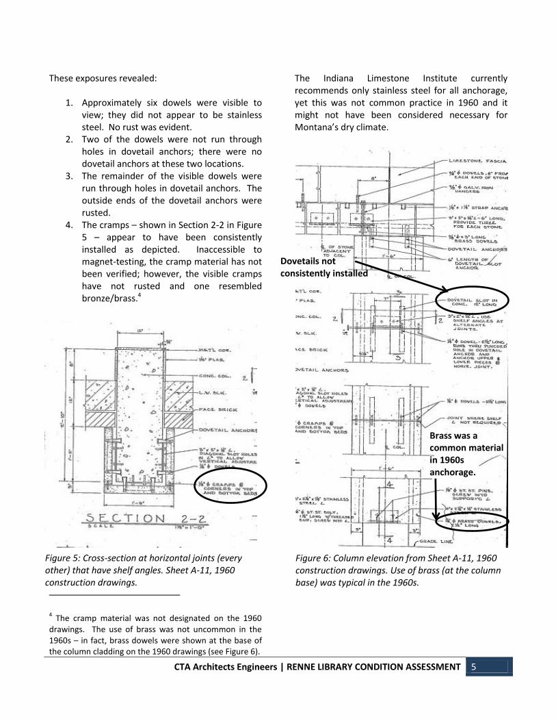
4. The cramps – shown in Section 2-2 in Figure 5 – appear to have been consistently installed as depicted. Inaccessible to magnet-testing, the cramp material has not been verified; however, the visible cramps have not rusted and one resembled bronze/brass.4
4 The cramp material was not designated on the 1960
drawings. The use of brass was not uncommon in the 1960s – in fact, brass dowels were shown at the base of the column cladding on the 1960 drawings (see Figure 6).
The Indiana Limestone Institute currently recommends only stainless steel for all anchorage, yet this was not common practice in 1960 and it might not have been considered necessary for Montana’s dry climate.
Figure 5: Cross-section at horizontal joints (every other) that have shelf angles. Sheet A-11, 1960 construction drawings.
Figure 6: Column elevation from Sheet A-11, 1960 construction drawings. Use of brass (at the column base) was typical in the 1960s.
Dovetails not consistently installed
Brass was a common material in 1960s anchorage.

6 RENNE LIBRARY CONDITION ASSESSMENT | CTA Architects Engineers
Stone Column Cladding - Description
Panels The stone panels appear to have been constructed in general accordance with the 1960 construction drawings, with a few exceptions in terms of anchorage.
Bottom Shelf Angles The only shelf angles accessible for inspection are the angles at the column base, which were confirmed to be stainless steel, as specified on Section 4-4 of Sheet 11 (see Figure 7).
Shelf Angles between Panels Shelf angles are located at alternate horizontal joints, providing compressive deadload support. None of the shelf angle details – see Figures 5, 6, & 8 – indicate the material of the angle. It is unknown if they are stainless steel or not.
Dowels & Dovetails Two vertical dowels are located at the top and bottom of each panel – both at the shelf angle joints and the joints where the shelf angle is not required, as shown in Figure 6 above. Physical investigation reveals that the dowels appear to be located as shown on the drawings and that the dowels are not of stainless steel. Dovetail anchors were not installed at one location examined during the investigation – it is presumed this lack occurs elsewhere. It is assumed that there is no compressible filler at the top and bottom of the dowel joints, which is the current practice, as this treatment is not noted in the details.
Cramps Horizontal cramps were designed to be located at the bed joints between the facing and the side panels, as shown in Figure 5. Such cramps were visible at a few locations; they did not appear to be rusted or damaged/distorted. As noted above, they might be of brass/bronze.
Mortar Joints All of the joints between the stone panels – and the stone and the adjacent brick wall – are narrow (3/16” to ¼” typically) and appear to be filled
completely with mortar for the full bed of the stone. Thus, the required pressure relieving joint
Figure 8: Detail Section 3-3, Sheet A-11 depicting typical shelf angle support to be located at every other horizontal joint between the stone panels. The angle material is not indicated here or on the other details shown in Figures 5 & 6 (1960 construction drawings).
The full depth of the joint is filled with mortar, not allowing for relief of pressure.
Figure 7: Vertical section 4-4 of the base of the column cladding, specifying the stainless steel support angle.

CTA Architects Engineers | RENNE LIBRARY CONDITION ASSESSMENT 7
beneath the shelf angles does not appear to have been provided. As noted in the Indiana Limestone Handbook, “As a general statement, installation of compressible material at the bottom and/or top of anchorage holes and slots will minimize the risk of high stress concentrations and potential stress failures in the stone at anchorage points.”5 Pressure-relieving joints are intended to prevent splitting and spalling at these support areas. The extant mortar appears to be the original mortar, of a white Portland, lime, and aggregate mix. Typical mixes were, and continue to be: “…one part cement, one part lime and six parts sand, all by volume. (Lime improves the workability of mortar and helps to reduce shrinkage.) This 1/1/6 mixture provides sufficient compressive strength, good bond strength and good weather resistance.”6 The aggregate appears to be light colored stones like marble, tooled in a slightly concave profile, then painted white to present a uniform color.
5 Indiana Limestone Institute of America, Inc., Indiana
Limestone Handbook: 22nd
Edition (Bedford, Indiana: Indiana Limestone Institute, 2007), page 30. 6 Ibid., page 22.
The 1” cavity behind the stone panels appears to have originally been filled completely with mortar. Current standards recommend keeping the cavities clear of mortar droppings, in order to prevent trapping moisture behind the panels.
Figure 9: The mortar appears to have been painted white originally. The rusted end of a dovetail anchor is indicated at the arrow point.
Rusted end of dovetail anchor
Figure 10: Where the paint has worn off the mortar, the fine grained marble-type aggregate is visible. The cramp connecting the tops of the two lower panels is indicated at the arrow point.
Cramp

8 RENNE LIBRARY CONDITION ASSESSMENT | CTA Architects Engineers
Stone Column Cladding – Condition
Panels The majority of the stone panels are intact, yet there are approximately two dozen spalls (or imminent spalls) adjacent to the joints. These spalls are attributed to the lack of relief at the shelf angles and to moisture trapped behind the stone panels. The trapped moisture has led to staining of the panels, which is more prevalent in some areas – such as the west entry columns and the coping. Some of the spalls have been patched, yet the patches are disengaging from the stone. There is only slight staining at most of the columns and imperceptible loss of surface finish.
Figure 11: Imminent spalling at a joint on the south facade.
Figure 12: Water run-off from the west canopy has infiltrated and stained the stone column cladding.
Figure 13: The staining is more prevalent at the south column of the west entry.

CTA Architects Engineers | RENNE LIBRARY CONDITION ASSESSMENT 9
Bottom Shelf Angles The bottom shelf angles appear to be in excellent condition, despite their proximity to snow accumulation, due to the durability of stainless steel. The bottom of several stone panels is chipped at the thin section in front of the support angle, probably from lawn maintenance equipment.
Shelf Angles between Panels None of the angles between panels are visible for inspection. There is no correlation between stone spalling and shelf angle location; thus it is conceivable that the angles are of stainless steel.
Dowels & Dovetails Where visible at eroded or missing mortar joints, the dowels appear to be in excellent condition; it is conceivable that they are of a non-corrosive metal. Only the end bars of some of the dovetail anchors are visible – at eroded or missing mortar joints. The dovetail anchor tabs are not extant at the furthest north column of the west elevation (2nd joint above grade). All visible anchor tabs have rusted. Unexpectedly, the stone faces that have shifted at the column immediately to the south of the northwest corner have complete dovetail anchors and dowels, and cramps. All of these components must have shifted slightly as the panel was free to move upon disintegration of the cavity’s mortar fill.
Cramps The cramps - where exposed at several locations – appear to be in excellent condition and to not have rusted. They don’t appear to have negatively affected the stone panels.
Mortar The mortar appears to be original, with little if any repointing or replacement since its 1960 installation. Approximately 10% of the mortar – primarily vertical – has fallen from the joints. This is primarily due to natural weathering and wind erosion. Most of the mortar at the vertical joint between the columns and the adjacent brick walls is aged and cracking, unable to flex with the slight differential movement. Where visible, it appears that the cavity between the stone panels and the
concrete structure was originally filled entirely with mortar, which would trap moisture in the cavity. This moisture has stained the stone and contributed to rusting of the dovetail anchor tabs.
Figure 14: The shifted face panel at the column south of the northwest corner of the building, at the west facade. The aged mortar in the joint above is cracking.

10 RENNE LIBRARY CONDITION ASSESSMENT | CTA Architects Engineers
Figure 16: The original mortar is aged and cracking - particularly at the vertical joint between the column and the brick wall.
Figure 17: The face panel at the west column just south of the northwest corner has shifted from the vertical plane.
Figure 18: The north side of the column face shown in Figure 17. The crimp is visible upon closer inspection.
Approximate location of ¼” cramp
Figure 15: The stone panels are slightly stained, primarily near the horizontal joints.

CTA Architects Engineers | RENNE LIBRARY CONDITION ASSESSMENT 11
Stone Column Cladding – Recommendations The following treatments are proposed to (Phase I) treat existing damage and to discover inherent causes of the evident failures, and to (Phase II) prevent further deterioration. Phase I – Repairs & Discovery:
1. Remove limestone spalls and patches. Provide matching cementitious patches with Jahn Patching Mortar.
2. Remove deteriorated mortar and repoint – approximately 10% of all joints.
3. Cut dowels at the two shifted face panels at the west façade. Remove the panels and examine all angles, anchors, materials, cavity mortar fill, and document conditions.
4. Reinstall the two original panels with stainless steel through-bolt anchors concealed with stone or composite plugs.
5. Wherever possible, the condition of all dowels, dovetail anchors (if extant), shelf angles, and cramps exposed during the above steps should be examined and documented.
6. Discovery: Remove 2-3 select panels to ascertain material, condition, and extent of all fasteners and anchors.
Phase II – Preventive / Long-term: 1. Remove all mortar from the vertical joints
between the columns and the brick wall. Fill with flexible high-lime mortar similar to original (1:1:6 proportion, as typical in 1960) or polyurethane (non-staining) sealant (noting that this will probably require greater maintenance).
2. Remove mortar to alleviate pressure beneath shelf angles – note this would be performed at every other joint, at locations of shelf angles.
3. Address corrections for damaged and rusted anchors, cramps, dowels, etc.
4. It is assumed that the above Discovery will not warrant removal and reinstallation of all the column panels.
Figure 19: The deteriorated mortar joint shown above is typical of approximately 10% of the joints. The original mortar is aged and cracking.
Figure 20: The thin stone section (3/8" thick) at the bottom shelf angle, at arrow, is vulnerable to chipping.

12 RENNE LIBRARY CONDITION ASSESSMENT | CTA Architects Engineers
Stone Coping/Soffit Cladding - Description The structure of the 1960 addition to Renne Library is expressed with limestone-clad concrete columns and the limestone-clad concrete beam that spans them at the top of the wall. The 1960 construction documents include the standard coping detail, as depicted in Figure 21.
Access to the soffit at the south façade was provided by lift operated by MSU Facilities staff. The condition at two of the imminent spalls was examined closely. The original roofing has been covered or replaced with a ballasted membrane roofing material.
Figure 21: Detail 1/11 from Sheet 11 of the 1960 construction documents.

CTA Architects Engineers | RENNE LIBRARY CONDITION ASSESSMENT 13
Stone Coping/Soffit Cladding – Condition
Stonework
The coping units have been infiltrated with water, which is evident by staining and spalling of the stone and by rusting of the strap anchors of the fascia below the coping. It appears that this water infiltration – and resultant staining and stone spalling - is ongoing and has not abated since the roofing replacement. Water probably entered the expansion joint behind the coping unit and continues to enter from open joints in the gravel stop. This condition is occurring at all elevations. Spalling at the top of the coping unit has been exacerbated by the introduction of the ferrous anchor used to fasten the wood blocking. This anchor was typically installed close to the original reglet, at a vulnerable location of the stone. The stone soffit panels, also stained, have benefited from the erosion of the mortar joint which is now acting as a weep hole for the moisture. This is an appropriate function of the mortar, and protects the angles and dowels supporting the fascia panel, which is open to outside air. However, at the
column locations, this weeping moisture is directed into the cavities of the column below. Some of the top column panels have subsequently shifted, presumably due to rusting anchorage. The condition of the concrete ledge - and the anchors in it - below the coping unit is unknown. It is presumed that water has penetrated this area; if the anchors are ferrous (i.e., not stainless steel or
Figure 22: Looking up at the wood blocking installed atop the stone coping unit, north facade.
Nail
1/8” Plastic Gravel Stop Plastic Flashing Ferrous Anchor Wood Blocking
Figure 23: Original coping detail on left. Current coping detail on right.
Solid Stone Coping Strap Anchor
Stone Fascia Panel
Stone Soffit Panel
Concrete Ledge Weep hole, where mortar eroded

14 RENNE LIBRARY CONDITION ASSESSMENT | CTA Architects Engineers
Figure 24: Spalling at the top of the solid stone coping unit, caused by impact damage from the blocking fastener and water infiltration. North façade.
Figure 26: Attempts have been made to patch the spalled stone below the roof flashing. Note staining of stone fascia and soffit below.
Figure 28: Spalling at coping units (as circled) at the south end of the west facade.
Figure 25: The rusted anchor atop the fascia panel has caused the stone to spall, at arrow. Circle at spall of coping unit above. North façade.
Figure 27: Imminent spall at rusting anchor of fascia panel, at arrow. North facade.
Figure 29: Spalled stone at anchor of fascia on south facade, within circle.
Patch

CTA Architects Engineers | RENNE LIBRARY CONDITION ASSESSMENT 15
brass) then they are likely rusting and expanding, just as several of the strap anchors have. There are at least a dozen spalled coping units (at the top, visible just below the new flashing) and at least half a dozen spalled (or imminently spalling) fascia panel units.
Mortar Joints The mortar joints are typically in good condition, with the exception of the vertical (head) joint between the soffit and the fascia. As noted above, portions of these joints have disintegrated from water infiltration. The loss of this mortar actually benefits the system, as it acts as a necessary weephole, providing a preferable escape path for the moisture (in lieu of penetrating the stone).
Figure 31: Water infiltrating the coping has no exit outside the system, thus it enters the cavities behind the column panels below.
See Figure 32 for enlarged image.
Figure 32: Enlargement of Figure 31. The top column panel is being pushed outward.
Figure 33: The mortar has been washed out of the joint between the soffit and the fascia, visible at the arrow points. South façade.
Figure 30: Looking down at open joint in gravel stop at the north roof.

16 RENNE LIBRARY CONDITION ASSESSMENT | CTA Architects Engineers
Stone Coping/Fascia Cladding – Recommendations The stone coping and fascia system can be approached in a similar to the two-phased treatment proposed for the column cladding. Phase I would treat the existing damage and be used to discover inherent causes of the evident failures, and Phase II would be implemented to prevent further deterioration. Phase I – Repairs & Discovery:
1. Seal the joints of the gravel stop at the roof. 2. Remove limestone spalls and patches. 3. At the (approximately 6) fascia panel repair
locations: Prepare (sandblast, wirebrush, etc. down to bare metal) the exposed rusting anchors and paint with industrial rust-resistant paint system. Or remove and abandon the rusted strap anchors, if able. Provide stainless steel through-bolts to adhere stone fascia panels, concealing fastener holes with cementitious patches or stone plugs.
4. At coping spall locations, provide matching cementitious patches with Jahn Patching Mortar, or adhere matching limestone Dutchman patches with stainless steel fasteners (concealed with matching cementitious patches).
5. Remove deteriorated mortar and repoint – approximately 5% of all joints, incorporating weepholes into the repointed head joints between the fascia and the soffit panels.
6. Discovery: a. Expose 2-3 spalled coping units by
removing and pulling back roofing components.
b. Remove the exposed coping units and related fascia panels; label and set aside for reinstallation.
c. Examine material, extent, and condition of exposed anchors, concrete, and limestone.
d. Replace all anchors and fasteners – for coping unit, fascia, and soffit - with stainless steel components.
e. Reinstall coping units and fascia panels, incorporating weep holes into head joint between fascia and soffit panels.
f. Reinstall roofing, flashing, and gravel stops. Seal all joints.
Phase II – Preventive / Long-term: It is assumed that the prior Discovery will warrant replacement of all the anchors.
1. Expose the full length of limestone coping, by removing and pulling back roofing components.
2. Remove all coping units and fascia panels; label for reinstallation at original locations.
3. Replace all anchors and fasteners - for coping unit, fascia, and soffit - with stainless steel components.
4. Reinstall coping units and fascia panels, incorporating weep holes into head joint between fascia and soffit panels. It is assumed that 8% of the units will be replaced in their entirety.
5. Reinstall roofing, flashing, and gravel stop. Seal all joints.
NOTE: The above recommendations do not include cleaning of the limestone, as this is considered a cosmetic improvement not necessary for proper function of the cladding.

CTA Architects Engineers | ESTIMATED COST OF REPAIRS 17
ESTIMATED COST OF REPAIRS The following estimate is provided in 2013 dollars and should be escalated accordingly if bidding
occurs more than six to nine months after the date of this report.
Item Estimated Construction Cost
1. Columns – Phase I Sub-Total $68,060
a. 10% Contingency $6,806
b. Columns - Phase I TOTAL $74,866
2. Columns – Phase II Sub-Total $98,988
a. 10% Contingency $9,899
b. Columns – Phase II TOTAL $108,886
3. Copings – Phase I Sub-Total $85,630
a. 10% Contingency $8,563
b. Copings – Phase I TOTAL $94,193
4. Copings – Phase II Sub-Total $244,214
a. 10% Contingency $24,421
b. Copings – Phase II TOTAL $268,636
The work should be performed by a qualified mason who has a proven, successful record of at least five years of working on historic masonry structures. Due to the nature of the work and the limited availability of qualified masonry contractors required for competitive bidding, this estimate is provided with the caveat that bids and work results will vary. Construction climate is also a key factor in actual construction costs. The inclusion of unit prices and alternates in the bidding documents is encouraged; this provides the ability to more closely structure the amount of available funds to fit the work required. Professional fees are estimated at 15% of the estimated construction costs, including reimbursable expenses. END OF REPORT
