renesas ra family security design with arm trustzone - ip
TRANSCRIPT

Application Note
R11AN0467EU0110 Rev.1.10 Page 1 of 57 Jun.2.21
Renesas RA Family Security Design with Arm TrustZone - IP Protection Introduction Arm® TrustZone® technology for ARMv8-M is an optional security extension that is designed to provide a foundation for improved system-level security in a wide range of embedded applications. This application note explains the various RA MCU TrustZone technology enabled hardware and software features and provides guidelines for utilizing these features. In addition, this application project walks users through step-by-step instructions to kickstart TrustZone technology enabled secure system design with Renesas RA Family MCUs.
For fundamentals of Arm TrustZone Technology, users are encouraged to read the document Arm® TrustZone Technology for the Armv8-M Architecture from Arm. The link to this document is provided in the References section. This application project focuses on RA Family MCU TrustZone technology implementation and features, and only provides brief introduction to Arm TrustZone technology.
Creating a secure design involves using hardware enforcement, software development for security as well as tooling support. For TrustZone based Security Design, tooling plays a critical role for the development, production, as well as deployment of a product. It is recommended that users read the FSP User’s Manual section: Primer: TrustZone Project Development prior to referencing this application project to start their first RA MCU TrustZone technology enabled project design. The link to this document is provided in the References section. Wherever needed, reference to this document is provided in this writeup.
An EK-RA6M4 based application project implementing an IP protection use case for TrustZone technology is provided as a reference project for users to start their application with the RA Family MCU TrustZone feature.
Required Resources Software and development tools • e2 studio IDE v2021-04 or later • Renesas Flex Software Package (FSP) v3.0.0 or later • SEGGER J-Link® USB driver
Note: The above three software components: the FSP, J-Link USB drivers, and e2 studio are bundled in a downloadable platform installer available on the FSP webpage at renesas.com/ra/fsp
• Download and install Renesas Flash Programmer (RFP) V3.08 or later using www.renesas.com/us/en/products/software-tools/tools/programmer/flash-development-toolkit-programming-gui.html#downloads
Hardware • EK-RA6M4, Evaluation Kit for RA6M4 MCU Group (renesas.com/ra/ek-ra6m4) • Workstation running Windows® 10; the Tera Term console, or similar application • One USB device cables (type-A male to micro-B male)
Prerequisites and Intended Audience This application project assumes that you have some experience with the Renesas e2 studio IDE and FSP. Please read the two reference documents mentioned in the Introduction section prior to proceeding with the hands-on exercises provided in this application project. In addition, we recommend reading the first two chapters of the application note Renesas RA Family Installing and Utilizing the Device Lifecycle Management Keys to understand the Device Lifecycle States of RA TrustZone technology enabled MCUs. Furthermore, users are required to know how to enter MCU boot mode using EK-RA6M4 and create a basic RFP project to communicate with the MCU. This application project only provides necessary settings for the specific functions used in this application project. For more information on the MCU boot mode and RFP, refer to the Renesas RA6M4 Group User’s Manual: Hardware and Renesas Flash Programmer User’s Manual.

Renesas RA Family Security Design with Arm TrustZone - IP Protection
R11AN0467EU0110 Rev.1.10 Page 2 of 57 Jun.2.21
The intended audience is all users who start developing Arm® TrustZone® based applications using Renesas RA Family MCUs.
Contents
1. Introduction to Arm® TrustZone® and its Security Features ...................................................... 4 1.1 TrustZone Technology Overview ............................................................................................................ 4 1.2 RA MCU Hardware Enforced Security using Arm® TrustZone® .............................................................. 5 1.2.1 Memory Separation ............................................................................................................................... 5 1.2.2 Bus System Separation ......................................................................................................................... 6 1.2.3 IO and Peripheral Separation ................................................................................................................ 6 1.2.4 Debug Interface ..................................................................................................................................... 7 1.3 Device Lifecycle Management ................................................................................................................ 8 1.4 Example TrustZone Use Cases .............................................................................................................. 8 1.4.1 Intellectual Property (IP) Protection....................................................................................................... 8 1.4.2 Root of Trust Protection ........................................................................................................................ 9
2. Arm® TrustZone® Application Design Supporting Software Features ....................................... 9 2.1 IDAU Region Setup ............................................................................................................................... 10 2.2 Non-Secure Callable Modules ............................................................................................................... 11 2.3 Guard Function for Non-Secure Callables ............................................................................................ 12 2.3.1 Limit Access to Selected Configurations and Controls ....................................................................... 12 2.3.2 Test for Non-Secure Buffer Locations ................................................................................................. 12 2.3.3 Handle Non-secure Data Input Structure as Volatile .......................................................................... 12 2.3.4 Limit the Number of Arguments in an NSC Function .......................................................................... 13 2.4 Creating User Defined Non-Secure Callable Functions ........................................................................ 13 2.5 RTOS Support ....................................................................................................................................... 14 2.6 Third Party IDE Support ........................................................................................................................ 14 2.7 Writing TrustZone Technology Enabled Software ................................................................................. 14 2.7.1 Benefitting from CMSE Functions to Enhance System Level Security ............................................... 14 2.7.2 Avoid Asynchronous Modifications to Currently Processed Data ....................................................... 15 2.7.3 Utilize the Armv8-M Stack Pointer Stack Limit Feature ...................................................................... 15
3. TrustZone technology enabled Application Development Process ......................................... 15 3.1 Combined Project Development ............................................................................................................ 17 3.1.1 Developing the Secure Project ............................................................................................................ 17 3.1.2 Developing the Non-secure Project .................................................................................................... 25 3.1.3 Production Programming ..................................................................................................................... 32 3.2 Split Project Development ..................................................................................................................... 32 3.2.1 Developing the Secure Bundle and Provisioning the MCU ................................................................. 32 3.2.2 Limitations and Workarounds for Developing in NSECSD state ......................................................... 32 3.2.3 Developing the Non-Secure Project in NSECSD State....................................................................... 33
4. Flat Project Development....................................................................................................... 36

Renesas RA Family Security Design with Arm TrustZone - IP Protection
R11AN0467EU0110 Rev.1.10 Page 3 of 57 Jun.2.21
4.1 Flat Project Development ...................................................................................................................... 37 4.2 Production Flow ..................................................................................................................................... 38
5. Example Project for IP Protection with e2 studio .................................................................... 38 5.1 Overview ................................................................................................................................................ 38 5.2 System Architecture .............................................................................................................................. 39 5.2.1 Software Components ......................................................................................................................... 39 5.2.2 Operational Flow ................................................................................................................................. 40 5.2.3 Simulated “User’s IP Algorithm” .......................................................................................................... 41 5.2.4 User Defined Non-secure Callable APIs ............................................................................................. 41 5.3 Running the Example Application ......................................................................................................... 42 5.3.1 Setting up Hardware ............................................................................................................................ 42 5.3.2 Import, Build, and Program the Secure Binary and Dummy Non-secure Binary ................................ 42 5.3.3 Import, Build, and Program the Non-secure Project ........................................................................... 46 5.3.4 Verify the Example Application ............................................................................................................ 47
6. Appendix A: Using RFP for Production Flow .......................................................................... 50 6.1 Initialize the MCU .................................................................................................................................. 50 6.2 Download the Secure Binary ................................................................................................................. 51 6.3 Download the Non-secure Binary .......................................................................................................... 53
7. Appendix B: Glossary ............................................................................................................ 55
8. References ............................................................................................................................ 55
9. Website and Support ............................................................................................................. 56
Revision History ............................................................................................................................ 57

Renesas RA Family Security Design with Arm TrustZone - IP Protection
R11AN0467EU0110 Rev.1.10 Page 4 of 57 Jun.2.21
1. Introduction to Arm® TrustZone® and its Security Features 1.1 TrustZone Technology Overview Arm® TrustZone® technology is a hardware-enforced separation of MCU features. Arm® TrustZone® technology enables the system and the software to be partitioned into Secure and Non-secure worlds. Secure software can access both Secure and Non-secure memories and resources, while Non-secure software can only access Non-secure memories and resources. These security states are orthogonal to the existing Thread and Handler modes, enabling both a Thread and Handler mode in both Secure and Non-secure states.
Figure 1. Processor States The Armv8-M architecture with Security Extension is an optional architecture extension. If the Security Extension is implemented, the system starts up in Secure state by default. If the Security Extension is not implemented, the system is always in Non-secure state. Arm TrustZone technology does not cover all aspects of security. For example, it does not include cryptography.
So, in designs with Armv8-M architecture with Security Extension, components that are critical to the security of the system can be placed in the Secure world.
These critical components include:
• A Secure boot loader • Secret keys • Flash programming support • High value assets The remaining applications are placed in the Non-secure world.
Figure 2. Secure and Non-secure Worlds

Renesas RA Family Security Design with Arm TrustZone - IP Protection
R11AN0467EU0110 Rev.1.10 Page 5 of 57 Jun.2.21
As mentioned in the introduction section, for more details on the definition and usage of TrustZone, see the Arm document, Arm® TrustZone Technology for the Armv8-M Architecture.
1.2 RA MCU Hardware Enforced Security using Arm® TrustZone® To build a Secure Hardware Platform, the security considerations need to go beyond the processor level. Renesas RA Arm® TrustZone® enabled MCUs extend the security arrangement to the entire system including:
• Memory system • Bus system • Access control to Secure and Non-secure peripherals • Debug system Note that the RA6M4 MCU Groups are used as a reference in this section. Other TrustZone technology enabled MCUs may have some variations in terms of the details for the hardware features. 1.2.1 Memory Separation Code flash, data flash, and SRAM on RA TrustZone technology enabled RA MCUs are divided into Secure (S), Non-secure (NS) and Non-secure Callable (NSC) regions via the IDAU (Implementation Defined Attribution Unit). These memory security attributions are programmed into the nonvolatile memory by using the serial programming commands when the device lifecycle is in Secure Software Development (SSD) state. For the Device Lifecycle State definition and transitions, see the RA6M4 User’s Manual: Hardware section, Security Features.
The following graphic shows a summary of the 8 available regions.
Figure 3. IDAU Regions Code and Data Flash TrustZone based Security Features Code and Data flash regions read from a Non-secure region will generate a TrustZone Secure Fault. Per the MCU design, the Code and Data Flash Programming and Erasing (P/E) mode entry can be configured to be available from only Secure software or from both Secure and Non-secure software.
By default, the MCU configures the Code and Data Flash P/E functionality available only from Secure software. The flash driver may be placed in the Secure partition and may be configured as Non-secure Callable through FSP to allow the Non-secure application to perform flash P/E operation.
Table 1. Secure Flash Region Read/Write Protection
Access Violation Error Report Flash read TrustZone Secure Fault: Reset or NMI Flash P/E mode entry Flash P/E Error Flag: handled by FSP flash driver
RA Family MCUs support temporary and permanent Flash Block Protections for both the Secure region and Non-secure region. For more details on the Code and Data Flash TrustZone technology enabled hardware features, see the Renesas RA6M4 Group User’s Manual: Hardware, Flash Memory section.
SRAM SRAM memory, such as SRAM0, that includes ECC region and Parity can be divided into Secure/Non-secure callable/Non-secure status with the Memory Security Attribution (MSA) and can be protected from

Renesas RA Family Security Design with Arm TrustZone - IP Protection
R11AN0467EU0110 Rev.1.10 Page 6 of 57 Jun.2.21
Non-secure access. When MSA indicates that an SRAM memory region is of Secure or Non-secure callable status, Non-secure access cannot overwrite them.
Table 2. Secure SRAM Region Read/Write Protection
Access Violation Error Report SRAM read Arm® TrustZone® Secure Fault: Reset or NMI SRAM write Arm® TrustZone® Secure Fault: Reset or NMI
1.2.2 Bus System Separation The IDAU region setup is consistent for CPU, DMAC and DTC. Master TrustZone filters are implemented for DMAC and DTC.
1.2.2.1 Master TrustZone Filter for DMA Controller and Data Transfer Controller Direct Memory Access Controller (DMAC) and Data Transfer Controller (DTC) are supervised by the Master TrustZone Filter. The TrustZone violation area of Flash and SRAM is detected in advance before access the bus. The Master TrustZone Filter in DMAC and DTC can detect the security areas of Flash area (code Flash and data Flash) and SRAM area (ECC/Parity RAM) defined by IDAU. When Non-secure channel accesses those addresses, the Master TrustZone Filter detects the security violation. Access to the address in violation is not granted. For both DMA and DTC, the detected access violation is handled as the “Master TrustZone Filter error”. A DMA_TRANSERR interrupt will be generated in response to the “Master TrustZone Filter error”.
Below are some additional comments on the DMAC Security Attribute:
• The Security Attribution can be configured individually for each channel. Each DMA channel can assume Secure or Non-secure attribute.
• Only secure code can configure whether DMAC can be started by Secure or Non-secure code. If DMAC is used in the Secure project, FSP will start DMA in Secure mode and disable Non-secure
project from accidentally Stop the DMAC by setting up the corresponding registers. 1.2.2.2 Ethernet DMA Controller RA6M4 requires EDMAC RAM buffers to be placed in TrustZone Non-secure RAM. EDMAC is hard coded as TrustZone Non-secure bus master. These hardware features allow the following two Ethernet code partitioning options:
• Run Ethernet code as Secure and EDMAC RAM buffer in Non-secure RAM • Run Ethernet code as well as EDMAC RAM buffer in Non-secure region FSP supports customer implementations with both options.
1.2.2.3 Bus Master MPU TrustZone Feature The Bus Master MPU is available for memory protection function for each bus master except for the CPU. Secure software can set up the Security Attributes of the Bus Master MPU.
Refer to the Renesas RA6M4 User’s Manual: Hardware and FSP User’s Manual for more details of the Security Attribute control for the bus systems.
1.2.3 IO and Peripheral Separation Most peripherals in the MCU can be configured to be Secure or Non-secure with several exceptions as shown in Table 3.

Renesas RA Family Security Design with Arm TrustZone - IP Protection
R11AN0467EU0110 Rev.1.10 Page 7 of 57 Jun.2.21
Peripherals are divided into two types.
• Type-1 peripherals have one security attribution. Access to all registers is controlled by one security attribution. Type-1 peripheral security attribution is set to the Peripheral Security Attribution Registers (PSARx: x = B to E) by the secure application. e2 studio and FSP provides convenient way to assign the PSARx. Different channels for the peripheral can assume different Security Attributes. For example, UART
Channel 0 and Channel 1 can have different Secure or Non-secure Attributes. • Type-2 peripherals have the security attribution for each register or for each bit. Access to each register
or bit field is controlled according to these security attributions. Type-2 peripheral security attribution is set to the Security Attribution register in each module by the secure application. For the Security Attribution register, see sections in the user manual for each peripheral. e2 studio and FSP provides configurability of majority of these peripherals with several exceptions
where sensible default settings have been made to provide better development experience. See the latest FSP User’s Manual for details for each peripheral.
Table 3. List of Type-1 and Type-2 Peripherals
Type Peripheral Type 1 SCI, SPI, USBFS, CAN, IIC, SCE9, DOC, SDHI, SSIE, CTSU, CRC, CAC, TSN,
ADC12, DAC12, POEG, AGT, GPT, RTC, IWDT, WDT Type 2 System control (Resets, LVD, Clock Generation Circuit, Low Power Modes,
Battery Backup Function), FLASH CACHE, SRAM controller, CPU CACHE, DMAC, DTC, ICU, MPU, BUS, Security setting, ELC, I/O ports
Always Non-Secure CS Area Controller, QSPI, OSPI, ETHERC, EDMAC The access permissions of type-2 peripherals are different by peripheral. See the Register Description section of each peripheral.
Table 4. Peripheral Access Control Based on Arm® TrustZone®
Permission Secure access Non-secure access Peripheral configured as secure Allowed Write ignored/Read ignored TrustZone Access
error is generated Peripheral configured as non-secure Allowed Allowed
Notes on Clock Generation Circuit (CGC) The Clock Generation Circuit has individual Security Attributes for each of the clock tree control. The current release of the tooling and FSP provides flexibility of below clock control schemes. • Entire Clock Tree is controlled from Secure Project only and locked down in Non-secure project. • Entire Clock Tree is controllable from the Non-secure Project as well as the Secure Project. Refer to Notes on Clock Control for the operational details. Peripherals that Support Non-secure Partition Operation Only As shown in Table 3, the following three peripherals have limitations in terms of their Security Attributes. • Ethernet: See to section 1.2.2 for the limitations on Ethernet application development • CA Area Controller, QSPI, OSPI: These peripherals are Non-secure peripherals only. FSP has support
for them to be used from all three Project Types. Refer to section 3 for the definitions of Project Types based on the Project Configurator.
1.2.4 Debug Interface For the Arm® TrustZone® technology enabled RA Family MCUs, the debug function is considered in three levels, DBG0, DBG1, DBG2, to support TrustZone technology enabled debugging and provide security in development, production, and deployed products.

Renesas RA Family Security Design with Arm TrustZone - IP Protection
R11AN0467EU0110 Rev.1.10 Page 8 of 57 Jun.2.21
• DBG2: The debugger connection is allowed, and there is no restriction to accessing memories and peripherals
• DBG1: The debugger connection is allowed, and restricted to access only non-secure memory regions and peripherals
• DBG0: The debugger connection is not allowed Debug level is determined corresponding to the device lifecycle state of product. See the Renesas RA6M4 Group User’s Manual: Hardware chapter on Security Feature section Device Lifecycle Management for more details.
Debug level regression is possible via the Device Lifecycle Management system. See the application note Renesas RA Family Installing and Utilizing the Device Lifecycle Management Key for the corresponding operational flows.
For Renesas RA TrustZone technology enabled MCUs, J-Link, E2 and E2 Lite debuggers are supported.
1.3 Device Lifecycle Management The RA Family TrustZone technology enabled MCUs incorporate enhanced Device Lifecycle Management System using TrustZone technology features and Secure Crypto Engine 9 (SCE9). The Device Lifecycle Management is important during TrustZone technology enabled application development, production, and deployment stages.
For the Device Lifecycle State definition and transitions, see the RA6M4 Hardware User’s Manual. For the creation, installations and use of the Device Lifecycle Management keys during development and production stage, see the application note Renesas RA Family Installing and Utilizing the Device Lifecycle Management Keys.
1.4 Example TrustZone Use Cases This application project explains two specific use cases for TrustZone technology and provides an example software project for the IP Protection use case.
For additional attack scenarios where an attacker may attempt to access protected information and how the TrustZone technology for ARMv8-M can prevent them, see chapter 2, Security of Arm® TrustZone Technology for the Armv8-M Architecture.
1.4.1 Intellectual Property (IP) Protection IP protection is a common need for proprietary software algorithms or data protection. TrustZone technology provides good hardware isolation for IP protection. TrustZone technology creates separation between two regions, secure (“trusted”) and non-secure (“non-trusted”) code/data. Customers which create building blocks for others to integrate can take advantages of the TrustZone technology feature by storing their software IP in the secure (“trusted”) region.
Business Model Not all software developers create end products. Some create building blocks, such as algorithms, for others to integrate to create an end product. One difficulty they face is the protection of their software IP. Their end customers would prefer to receive source code, but source code can easily be copied and redistributed. Even binary libraries aren’t complete protection, as there are tools that can disassemble binaries to assembly and even C source code.
TrustZone technology enables new business models for these developers where they can program their algorithms into the secure region of a TrustZone-enabled MCU and sell a value-added MCU, with their IP protected by TrustZone and the Device Lifecycle Management (DLM) system of the RA MCU.
RA MCU Device Lifecycle Management Feature for IP Protection During development, DLM state regression allows erasing the protected areas of flash (unless permanently locked). This prevents reading of the protected area of the flash and hence protects the IP and eliminates scrappage of devices in case the algorithms need to be modified.
In production, if the algorithm developer would like to retain the potential to debug their algorithms with the application in place, they can install DLM keys for the NSECSD to SSD and DPL to NSECSD transitions. Refer to the Renesas RA Family Installing and Utilizing the Device Lifecycle Management Keys application note for the definition of the Device Lifecycle States and State regression operational flow.

Renesas RA Family Security Design with Arm TrustZone - IP Protection
R11AN0467EU0110 Rev.1.10 Page 9 of 57 Jun.2.21
RA MCU Flash Block Locking Feature for IP Protection RA MCUs support temporary and permanent Flash Block Protections. This allows customer IP and Root of Trust to be protected from accidental erasure and alteration. IP Protection Development, Production and Deployment Flow
Figure 4. IP Protection using Arm® TrustZone® Designing for IP protection uses the “Split Project Development Model”. See section 3.2 for the operational details.
1.4.2 Root of Trust Protection The Root of Trust (RoT) is a product’s security foundation. All higher-level security is built on top of the RoT. RoT also implements recovery features for higher-level security breaches. When Root of Trust is breached, recovery is not possible and can lead to serious consequences. For IoT applications, Root of Trust may encapsulate authenticated firmware updates and secure internet communication.
To reduce the attack surface, the functionality included in the RoT should be as little as possible. Typical services in the RoT are described in Figure 5 as shown below.
Figure 5. Root of Trust Protection – Put as Less as Possible in the Secure Region All other application code and device drivers should be considered to be allocated to the Non-secure region.
2. Arm® TrustZone® Application Design Supporting Software Features This chapter introduces several IDE features that are established to simplify the Software development when using the TrustZone hardware isolation with support from other MCU hardware components, FSP software or tooling.

Renesas RA Family Security Design with Arm TrustZone - IP Protection
R11AN0467EU0110 Rev.1.10 Page 10 of 57 Jun.2.21
2.1 IDAU Region Setup From the factory, RA MCUs are delivered to the developer in CM (Chip Manufacturing) Lifecycle State. The MCU must be transitioned to SSD (Secure Software Development) Lifecycle State prior to setting up the IDAU regions.
RA Family Evaluation Kit and supporting tools provide a convenient way for handling the transition from CM to SSD state.
• Necessary values to set up the TrustZone memory partition (IDAU registers) will be calculated after the binary code to program into the secure region is created by building the secure project. The regions are set up to ensure that they match the code and data sizes and keep the attack surface as small as possible.
• When the first secure program is downloaded to the MCU, the MCU will be automatically transitioned from CM to SSD state.
• The IDAU registers will be set upon the download of the secure project binary prior to the MCU reset. • User can use the Renesas Device Partition Manager to read out the IDAU regions currently set up for
the MCU as shown in Figure 7.
Figure 6. Open the Renesas Device Partition Manager

Renesas RA Family Security Design with Arm TrustZone - IP Protection
R11AN0467EU0110 Rev.1.10 Page 11 of 57 Jun.2.21
Figure 7. Read out the IDAU Region Setup using Renesas Device Partition Manager • Every subsequent new secure program download to the MCU will update the IDAU region setup based on
the new setting. It is important to note that the above functionalities depend on the hardware design as well. Hardware design using RA6M4 must reference the EK-RA6M4 debug interface design to provide proper connection to support the above functionality.
User needs to review the FSP User’s Manual section: Primer: Arm® TrustZone® Project Development section IDAU registers and EK-RA6M4 Hardware User’s Manual to understand how to prepare the hardware interface for IDAU region setup during development with RA Family TrustZone technology enabled MCUs.
2.2 Non-Secure Callable Modules Some driver and middleware stacks in the Secure project may need to be accessed by the Non-secure partition. To enable generation of NSC veneers, set Non-Secure Callable from the right-click context menu for the selected modules in the Configurator.
Note: It is only possible to configure top of stacks as NSC.

Renesas RA Family Security Design with Arm TrustZone - IP Protection
R11AN0467EU0110 Rev.1.10 Page 12 of 57 Jun.2.21
Figure 8. Generate NSC Veneers
2.3 Guard Function for Non-Secure Callables Access to NSC drivers from a Non-secure project is possible through the Guard APIs. FSP will automatically generate guard functions for all the top of stack/driver APIs configured in the secure project as Non-Secure Callable.
Some best practices and guidelines that the user should exercise when using the guard function are listed as follows.
2.3.1 Limit Access to Selected Configurations and Controls The default guard functions generated will ignore p_ctrl and p_cfg arguments sent in from NS side. Instead, the guard function will provide static Secure region instances of these data structures based on the module Instance.
BSP_CMSE_NONSECURE_ENTRY fsp_err_t g_uart0_open_guard( uart_ctrl_t *const p_api_ctrl, uart_cfg_t const *const p_cfg) { /* TODO: add your own security checks here */ FSP_PARAMETER_NOT_USED(p_api_ctrl); FSP_PARAMETER_NOT_USED(p_cfg); return R_SCI_UART_Open(&g_uart0_ctrl, &g_uart0_cfg); }
Figure 9. Example Guard Function
2.3.2 Test for Non-Secure Buffer Locations • If the Non-secure region is providing input (such as by calling the write () function with data buffer),
then guard functions should check that data buffer is entirely within an NS area • If the Non-secure region is providing a pointer to store output (such as by calling the read () function
with a pointer of where to store), then guard functions should check that the data buffer is entirely within a NS area.
See section 2.7.1 for examples of using the CMSE library to handle this requirement.
2.3.3 Handle Non-secure Data Input Structure as Volatile If a Non-secure region is providing a data structure as input (for example, a typedef'd structure with 3 members) then guard functions should make a copy of the data structure in the Secure region before passing to the Secure function. This is done because Non-secure data structure should be seen as volatile and the Non-secure region could alter contents after invoking the NSC function.
See section 2.7.2 for an example of how to handle this requirement.

Renesas RA Family Security Design with Arm TrustZone - IP Protection
R11AN0467EU0110 Rev.1.10 Page 13 of 57 Jun.2.21
2.3.4 Limit the Number of Arguments in an NSC Function The compiler uses registers R0 to R3 to pass parameters and return values. Registers R4 to R12 are used during function execution. The called function restores registers R4 to R12. Hence, if an NSC API is being used for a Secure function with more than 4 arguments, the guard function should define a function with a different prototype that will be a funnel to handle all the arguments. The new function prototype should take a data structure that has members to cover all parameters in the Secure function. This means that Non-secure code will need to put the function arguments into the structure. The guard function will then expand the data structure into separate arguments and pass to the Secure function.
The following figure shows an FSP example for funneling the 5 arguments from the R_SPI_WriteRead function to 4 arguments in the NSC API guard function.
Figure 10. Handling Secure Functions with More than 4 Arguments
2.4 Creating User Defined Non-Secure Callable Functions For IP protection purposes, a user can create a customized NSC API in the Secure project to expose only the top-level control of their algorithms and store the IP in secure Arm® TrustZone® region. Precautions mentioned previously should be exercised during the creation of user defined NSC API.
Steps to create a customized NSC API are as follows:
1. Create the non-secure callable custom function by declaring the function with BSP_CMSE_NONSECURE_ENTRY.
2. Create a header file with includes all the customized NSC function prototypes, for example, my_nsc_api.h.
3. Include the path to the NSC header using the Build Variable as shown below. 4. Compile the Secure Project to create the secure bundle. The NSC header will be automatically extracted
in the Non-secure project for use.

Renesas RA Family Security Design with Arm TrustZone - IP Protection
R11AN0467EU0110 Rev.1.10 Page 14 of 57 Jun.2.21
Figure 11. Link User Defined Non-secure Callable API Header File
2.5 RTOS Support Renesas tooling and FSP support Non-secure partition RTOS integration with Secure region access via Non-secure callable APIs. Secure projects can use Secure TrustZone Support – Minimum project type to add the Arm® TrustZone® Context RA port. For operation details, see section 3.1.1, Step 3 for Secure Project handling and section 3.1.2, Step 5 Non-secure Project Handling.
2.6 Third Party IDE Support Third party IDEs such as IAR Systems EWARM and Keil MDK (uVision) are supported by the RA Smart Configurator (RA SC). See FSP User’s Manual section RA SC User Guide for MDK and IAR to gain background knowledge on developing with these third-party IDEs.
2.7 Writing TrustZone Technology Enabled Software Security design using TrustZone technology has some specific challenges that secure developers should bear in mind and take corresponding actions when writing the secure application software.
This section provides several guidelines that secure software developers should consider following in order to avoid secure information leak to the Non-secure region.
2.7.1 Benefitting from CMSE Functions to Enhance System Level Security This subsection discusses how to benefit from the CMSE library to improve the secure software design. Some examples of the CMSE functions are:
• cmse_check_address_range: For example, this function can be used to confirm the address range is entirely in the Non-secure region
• cmse_check_pointed_object: For example, this function can be used to confirm the memory pointed to by the pointer is entirely in the Non-secure region

Renesas RA Family Security Design with Arm TrustZone - IP Protection
R11AN0467EU0110 Rev.1.10 Page 15 of 57 Jun.2.21
BSP_CMSE_NONSECURE_ENTRY fsp_err_t g_uart0_read_guard(uart_ctrl_t *const p_api_ctrl, uint8_t *const p_dest, uint32_t const bytes) { /* Verify all pointers are in non-secure memory. */ uint8_t *const p_dest_checked = cmse_check_address_range ((void*) p_dest, bytes, CMSE_AU_NONSECURE); FSP_ASSERT (p_dest == p_dest_checked); /* TODO: add your own security checks here */ FSP_PARAMETER_NOT_USED (p_api_ctrl); return R_SCI_UART_Read (&g_uart0_ctrl, p_dest_checked, bytes); }
Figure 12. Non-secure Buffer Address Range Check
2.7.2 Avoid Asynchronous Modifications to Currently Processed Data An example of handling is shown in Figure 13. When the pointer p points to Non-secure memory, it is possible for its value to change after the memory accesses used to perform the array bounds check, but before the memory access is used to index the array. Such an asynchronous change to Non-secure memory would render this array bounds check useless.
int array[N]; void foo(volatile int *p) {
int i = *p; if (i >= 0 && i < N) { array[i] = 0; }
}
Figure 13. Treat Non-secure Data as Volatile in Secure Code
2.7.3 Utilize the Armv8-M Stack Pointer Stack Limit Feature The Armv8-M architecture introduces stack limit registers that trigger an exception on a stack overflow.
CM23 with Arm® TrustZone® technology has two stack limit registers in Secure state:
• Stack Limit Register for Main Stack: MSPLIM_S • Stack Limit Register for Process Stack: PSPLIM_S CM33 with TrustZone technology has two stack limit registers in Secure state and two stack limit registers in Non-secure state:
• Stack Limit Register for Main Stack in Secure state: MSPLIM_S • Stack Limit Register for Process Stack in Secure state: PSPLIM_S • Stack Limit Register for Main Stack in Non-secure state: MSPLIM_NS • Stack Limit Register for Process Stack in Non-secure state: PSPLIM_NS Users can implement customized fault handlers to catch the stack limit overflow error.
Users can refer to Arm®v8-M Architecture Reference Manual section The Armv8-M Architecture Profile for more information on the functionality of the stack limit registers.
3. TrustZone technology enabled Application Development Process The Renesas e2 studio IDE is designed for TrustZone technology based application. It provides ease of use based on the following implementation features from the Tools and FSP point of view:
• Powerful RA Project Generator to guide the users through the TrustZone project creation process. • TrustZone IDAU region setup during secure program download, calculated automatically based on the
Secure Project. See to section 2.1 for more details. • Renesas Flexible Software Package (FSP) provides a quick and versatile way to build secure connected
IoT devices using an Renesas RA MCU. Note that in this document, the FSP version information is removed from the screen capture because these instructions apply to all FSP version 2.0.0 or later. This claim applies to all the following sections.

Renesas RA Family Security Design with Arm TrustZone - IP Protection
R11AN0467EU0110 Rev.1.10 Page 16 of 57 Jun.2.21
RA Project Generator RA Project Generator provides three project types to create the initial template projects for developing with Arm® TrustZone® technology enabled MCUs:
• A Secure Project and Non-secure Project Type pair which work with the Secure and Non-secure partitions respectively
• Flat Project with which application can be developed with no TrustZone partition awareness
Figure 14. RA Project Generator For RA TrustZone technology enabled MCUs, there are two development models. The design process based on each of these two development models are introduced in the subsequent subsections. The design process based on the Flat Project Type is introduced in section 4.
• Combined Project Development Secure and Non-secure applications are developed by one trusted team
• Split Project Development Secure and Non-secure applications are developed by two different teams Non-secure application team does not have direct access to Secure partition assets. Access to
Secure partition is only possible via Non-secure Callable APIs.

Renesas RA Family Security Design with Arm TrustZone - IP Protection
R11AN0467EU0110 Rev.1.10 Page 17 of 57 Jun.2.21
3.1 Combined Project Development With the Combined Project Development Model, Secure and Non-secure projects are developed by a single trusted team. A Secure project must reside in the same workspace as the Non-secure project and will typically be used when a design engineer has access to both the Secure and Non-Secure project sources.
In addition, a secure .elf file will be referenced and included in the debug configuration for Debug build for download to the target device. The development engineer will have visibility of Secure and Non-Secure project source code and configuration.
3.1.1 Developing the Secure Project Most peripherals and IO defined in the Secure project are configured as Secure with the exceptions of Clock, QSPI, OSPI and the CS Area. These peripherals can be used in the Secure project and be configured as Non-secure.
The major IDE operational steps in developing the Secure project are explained in the following steps. Step 1: Create a New Project using the RA Project Generator Template Renesas RA MCU tooling provides several project templates to assist users in kickstarting their development. Figure 15 to Figure 19 show some common steps when creating a new project with e2 studio regardless of whether Secure or Non-secure projects are to be created with either the Split Project Development Model or Combined Project Development Model. • This step will be referenced in the context of Non-secure Project Development for the Combined Project
Development Model • This Step will be referenced in context of Secure and Non-secure Project Development for the Split
Project Development Model
Figure 15. Create New Project

Renesas RA Family Security Design with Arm TrustZone - IP Protection
R11AN0467EU0110 Rev.1.10 Page 18 of 57 Jun.2.21
Figure 16. Select “Renesas RA C/C++ Project” Click Finish and then provide the Secure project name. Notice that it may be helpful to attach “_s” (for Secure”) and “_ns” (for Non-secure) to the end of the project name as a reminder of the security nature of this project.
Figure 17. Define the Name of the Secure Project

Renesas RA Family Security Design with Arm TrustZone - IP Protection
R11AN0467EU0110 Rev.1.10 Page 19 of 57 Jun.2.21
Click Next and then select the EK-RA6M4 BSP.
Figure 18. Select the BSP Note that by default, the BSP functionality with regards to Security control is only enabled in the Secure project.
Once the BSP is selected, click Next, then see the summary for the hardware setup page.
Figure 19. Review the Configurations prior to Proceeding to Next Step Once again, click Next and proceed to the following steps.
Note that Step 2 to Step 7 below are common for the Split Project Development Model and Combined Project Development Model.
These steps are referred to in context of the Secure Project development for the Split Project Development Model. Step 2: Choose the Secure Project as the Project Type Choose Secure Project as the project type and take a moment to read the description on this project type. All peripherals initialized in this project will be assumed to have the Secure attribute with the exceptions indicated in Table 3 as Always Non-secure. All code and data placed in this project will be initialized as

Renesas RA Family Security Design with Arm TrustZone - IP Protection
R11AN0467EU0110 Rev.1.10 Page 20 of 57 Jun.2.21
secure by the FSP BSP and control will be passed to Non-secure project reset handler at the end of the Secure project execution.
Figure 20. Choose the Secure Project Type Click Next and choose the Project Template.

Renesas RA Family Security Design with Arm TrustZone - IP Protection
R11AN0467EU0110 Rev.1.10 Page 21 of 57 Jun.2.21
Step 3: Choose the Project Template
Figure 21. Choose the Project Template As shown in Figure 21, there are three Secure Project templates:
• Bare Metal – Minimal Secure project with MCU Initialization function with supports on transitioning to Non-secure partition. This write up uses this Project Template as example to explain the general steps creating a secure project.
• TrustZone Secure RTOS - Minimal Secure projects will add the corresponding RTOS context in the Secure region for the Thread which
needs to access the NSC APIs in an RTOS enabled project. When this project type is selected, the Arm TrustZone Context RA Port will be added as shown in Figure 22.
The RTOS kernel and user tasks will reside in the Non-secure partition. Click Finish to allow the Project Generator to populate the Template Project.
Figure 22. Adding the TrustZone Context RA Port

Renesas RA Family Security Design with Arm TrustZone - IP Protection
R11AN0467EU0110 Rev.1.10 Page 22 of 57 Jun.2.21
Notes on Clock Control The clock will be initialized in the secure project to allow faster start up. By default, FSP sets all the security attributes of the Clock Generation Circuit (CGC) to be Non-secure as shown in Figure 23. Therefore, both Secure and Non-secure projects can change the clock setting.
The user has option to set all the security attributes of CGC as Secure, thus the Non-secure project developer cannot override the secure project setting as shown in Figure 24.
Details on the Lock Icon
Figure 23. Secure Project sets Clock as Secure
Figure 24. Non-secure Project Clock control “Override and Restore Default” Disabled

Renesas RA Family Security Design with Arm TrustZone - IP Protection
R11AN0467EU0110 Rev.1.10 Page 23 of 57 Jun.2.21
Step 4: Generate Project Content and Compile the Project Template Double click Configuration.xml to open the configurator. Click Generate Project Content as shown in Figure 25.
Figure 25. Generate Project Content Right-click on the project and select Build Project.
Figure 26. Compile the template project Note that by default, the GPIO driver to control the Secure GPIO pins is included in the template. The user can remove it if it is not needed, to reduce the project footprint.

Renesas RA Family Security Design with Arm TrustZone - IP Protection
R11AN0467EU0110 Rev.1.10 Page 24 of 57 Jun.2.21
The following is an example of the compilation result based on Bare-Metal Minimum project template.
Figure 27. Compilation Result of the Bare-Metal Minimum Secure Template Project Step 5: Review the Initial Secure Bundle Generated After successful compilation, the secure bundle <project_name>.sbd is generated as shown in Figure 28.
Figure 28. Secure Bundle Generated Step 6: Develop the Secure Application During the product development, th euser is likely to go through the following steps iteratively prior to completing development: • Add Needed FSP Modules
Define NSC Modules if needed. See section 2.2 for details. Note: Ethernet cannot be used in the Secure Project. It is only available in the Non-secure Project.
• Create User Defined Non-secure Callable Functions if needed. See section 2.4 for details. • Develop the Secure applications
Design the code flow such that the Secure applications which are not Non-secure Callable are executed prior to starting the Non-secure project execution: prior to function call R_BSP_NonSecureEnter();
• Recompile and test the application

Renesas RA Family Security Design with Arm TrustZone - IP Protection
R11AN0467EU0110 Rev.1.10 Page 25 of 57 Jun.2.21
Step 7: Debug the Secure Project in Isolation With the Combined Project Development, the Secure project is typically not debugged in isolation from the Non-secure project. To debug a Secure project on its own, user can use the following two options:
• Prepare a “dummy/test” Non-secure project. This approach offers the benefits of allowing the Non-secure Callable APIs to be debugged in the test Non-secure project.
• Replace R_BSP_NonSecureEnter(); with while(1); in hal_entry.c and debug the Secure Project by itself. Important reminder: The user needs to restore the R_BSP_NonSecureEnter(); after debugging
the Secure project prior to provisioning the Secure project to the MCU. Step 8: Debug the Secure Project with the Non-secure Project For the Combined Project Development model, Secure and Non-secure project development can be debugged in one workspace. Debugging the Secure project typically does not happen in an isolated manner for the Combined Project Development model. See section 3.1.2, Step 7 for operational details. 3.1.2 Developing the Non-secure Project Once the Secure Template Project is established and compiled, the user can start the Non-secure template project creation in the same workspace where the Secure project resides.
Step 1: Follow Step 1 in section 3.1.1 to start a new Non-secure project. Note that it may be helpful to attach “_ns” to the end of the project name as a reminder of the security configuration of this project.
Step 2: Choose Non-secure project as the Project Type.
Figure 29. Choose Non-secure Project as Project Type

Renesas RA Family Security Design with Arm TrustZone - IP Protection
R11AN0467EU0110 Rev.1.10 Page 26 of 57 Jun.2.21
Step 3: Establish linkage to the Secure project which resides in the same e2 studio workspace. Click the down arrow and select the secure project bare_metal_minimum_s created in section 3.1.1. Note that the Secure project must exist in the same workspace AND be open for it to be referenced in the selection box. The secure project must also be built to create the information used to set up the Non-secure project.
Figure 30. Establish Linkage to the Secure Project Click Next to proceed.
Step 4: Follow the prompt as shown below to choose whether the Non-secure project will have RTOS support.
Figure 31. Choose Whether to Use FreeRTOS in the Non-secure Project Click Next to proceed.

Renesas RA Family Security Design with Arm TrustZone - IP Protection
R11AN0467EU0110 Rev.1.10 Page 27 of 57 Jun.2.21
Step 5: Select the Project Template to Finish Creating the Non-Secure Template Project • If FreeRTOS is selected, the Project Generator provides the following two project templates. Choose the
project template based on the application needs.
Figure 32. Template Options for FreeRTOS enabled Projects Note that if FreeRTOS is selected and there is access to NSC functions from a thread in the Non-secure project, it is necessary to enable Allocate secure context for this thread in the configurator for that thread.
Figure 33. Enable Secure Context Allocation

Renesas RA Family Security Design with Arm TrustZone - IP Protection
R11AN0467EU0110 Rev.1.10 Page 28 of 57 Jun.2.21
• If No RTOS is selected, the project generator provides the following two project templates. Note that No RTOS selection must be selected if a new RTOS other than FreeRTOS is to be integrated in the Non-secure project.
Figure 34. Template Options for Non-FreeRTOS usage

Renesas RA Family Security Design with Arm TrustZone - IP Protection
R11AN0467EU0110 Rev.1.10 Page 29 of 57 Jun.2.21
• Click Finish to create the corresponding template project. Note that even though there are security properties allowed for configuration in the BSP Properties page, they are not being enabled with the current IDE support. The following attributes cannot be configured from the Non-secure project:
Figure 35. Attributes That Are Not Configurable from a Non-secure Project • By default, the Non-secure project BSP can reconfigure the MCU clock. Refer to Notes on Clock Control. Step 6: Follow Instructions from Step 1, section 3.1.1 to Generate Project Content and Compile the Non-secure Project Notice that both the secure project bare_metal_minimun_s and bare_metal_minimum_ns reside in the same workspace.
Renesas RA Family Security Design with Arm TrustZone - IP Protection
R11AN0467EU0110 Rev.1.10 Page 30 of 57 Jun.2.21
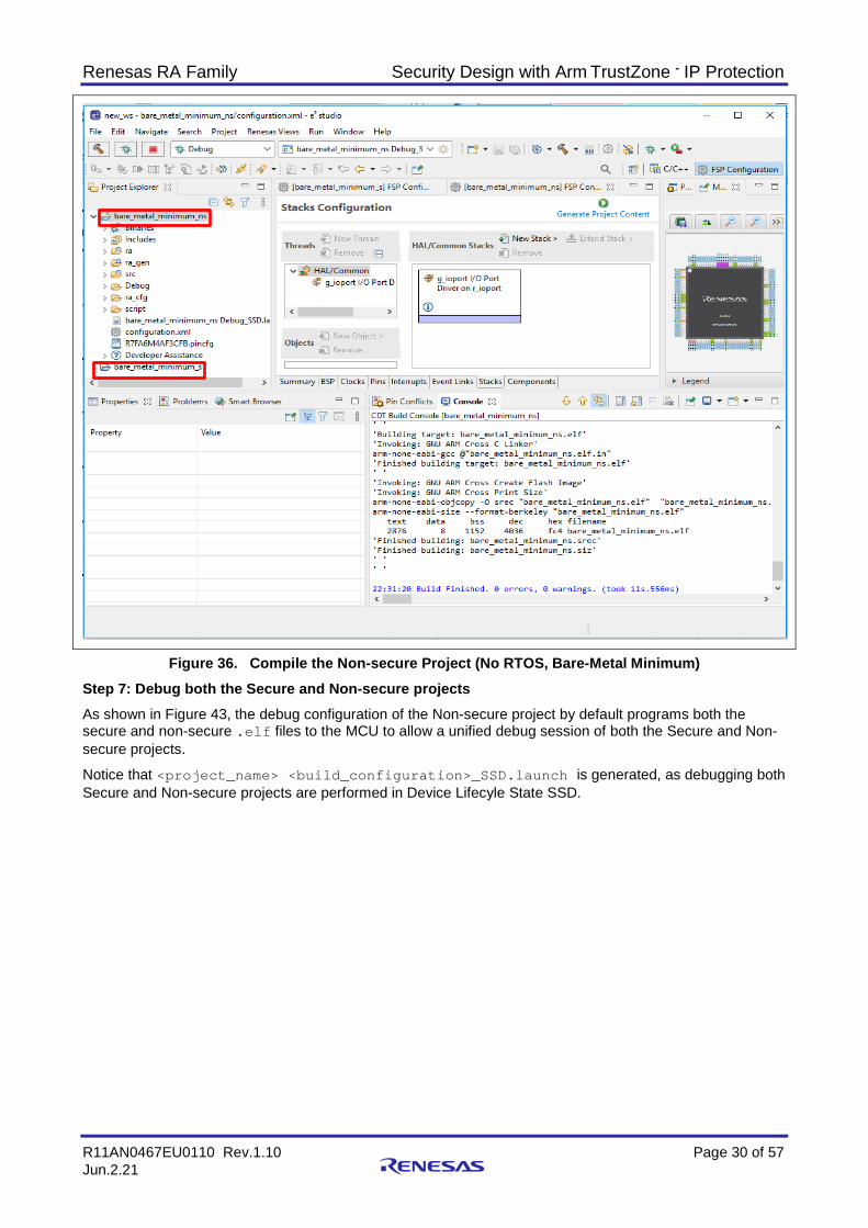
Figure 36. Compile the Non-secure Project (No RTOS, Bare-Metal Minimum) Step 7: Debug both the Secure and Non-secure projects As shown in Figure 43, the debug configuration of the Non-secure project by default programs both the secure and non-secure .elf files to the MCU to allow a unified debug session of both the Secure and Non-secure projects. Notice that <project_name> <build_configuration>_SSD.launch is generated, as debugging both Secure and Non-secure projects are performed in Device Lifecyle State SSD.

Renesas RA Family Security Design with Arm TrustZone - IP Protection
R11AN0467EU0110 Rev.1.10 Page 31 of 57 Jun.2.21
Figure 37. Debug Both the Secure and Non-secure Projects Note that the Secure project MUST be built each time it is changed to ensure that the connection to the Non- Secure project is maintained. When the Secure bundle changes, there will be a popup window asking the user to take the latest Secure bundle. Click Yes and then recompile the Non-secure project so that the updated <project_name>.sbd will be used.
Figure 38. Secure Bundle Update Notification Tips on Ensuring Synchronization between Secure and Non-secure Project
To avoid accidental update from Secure Project being missed, the user can also define the Secure project as a reference to the Non-secure project so that compiling the Non-secure project will automatically trigger a compilation to the Secure project.
Open the Properties page of the Non-secure project, click Project References and choose the corresponding Secure project as the Reference project. Once this is set up, compiling the Non-secure project will always trigger the Secure project to be recompiled.
Figure 39. Create Project Reference

Renesas RA Family Security Design with Arm TrustZone - IP Protection
R11AN0467EU0110 Rev.1.10 Page 32 of 57 Jun.2.21
3.1.3 Production Programming This step is for production flow; it is not a step needed during development. Once both Secure and Non-secure project development is finished, the user can send the following information to the production line for the MCU to be provisioned prior to selling:
• Secure binary • Non-secure binary • IDAU region configuration The user can refer to Appendix A, section 6.2 to program the secure binary and section 6.3 to program the Non-secure binary, and transition the MCU state to deployed state.
3.2 Split Project Development The following are the Split Project Development model characteristics:
• The Secure project and Non-secure project are developed separately by two different teams • The Secure project will be developed first by the IP provider. The IP provider creates a secure bundle. • The Secure bundle is pre-programmed on the device prior to non-secure developer starts the
development. Only Non-secure project and Non-secure partition is visible to the Non-secure developer. The following section will walk users through the development process using Split Project Development model.
3.2.1 Developing the Secure Bundle and Provisioning the MCU Developing the Secure project using the Split Project Development is very similar to the Combined Project development model. However, several key differences are explained in this section.
Step 1: Follow Step 1 to Step 6 from section 3.1.1 to establish the Secure template project and create the applications. Debugging the Secure project with the Split Project Development model will not happen with the Non-secure project for the product. As explained in Step 7, section 3.1.1, the user can create a dummy Non-secure project for the purpose of Secure project testing, for example to test the Non-secure callable APIs.
Step 2: Provision the MCU with the Secure project and change the Device Lifecycle State to NSECSD A major difference between the Split Project Development and the Combined Project Development is the Secure binary associated with the Secure bundle needs to be provisioned to the MCU prior to the Non-secure Project Development for the Split Project Development. The Secure bundle contains the Secure project IP in binary format and NSC API interface from Secure project. In addition, the MCU Device Lifecycle state needs to transition from SSD to NSECSD to protect the Secure content.
3.2.2 Limitations and Workarounds for Developing in NSECSD state There is a limitation with the current version of the tools in that a dummy Non-secure project MUST be provisioned on the device in addition to the Secure binary, prior to changing the MCU Device Lifecyle from SSD to NSECSD with the Split Project Development model. This is necessary to allow the Non-secure development to resume in NSEDSD state.
• In the development stage, users should follow the Combined Project Development model to prepare a dummy Non-secure project paired with the intended Secure project. Program the Secure binary and the dummy Non-secure binary first and then change the Device Lifecycle State to NSECSD.
• In the production stage, users should send the following two items to the production team: Secure binary IDAU region setup information RFP will be used to program the Secure binary and set up the IDAU region. See Appendix A, section 6.2 for the operational details.
• Note that the Secure developer also needs to provide the Secure bundle “<project_name>.sbd” to the Non-secure developer to allow Non-secure project to proceed to development.
• See Figure 40 for details on the general flow to support Non-secure project development in NSECSD state.

Renesas RA Family Security Design with Arm TrustZone - IP Protection
R11AN0467EU0110 Rev.1.10 Page 33 of 57 Jun.2.21
3.2.3 Developing the Non-Secure Project in NSECSD State Developing a Non-secure project using the Split Project Development model has some key differences compared with the Combined Project Development model.
For the split development model, the Non-secure application developer receives the MCU in NSECSD state. As mentioned towards the end of last section, special handling is needed to enable development in NSECSD state. The following is a summary of the general flow for developing in NSECSD state.
Figure 40. Development Flow for Developing in NSECSD State Once the Non-secure developers receive the MCU provisioned with the Secure binary, IDAU region and the Non-secure dummy binary in NSECSD state, they can use the following steps to proceed to the Non-secure project development.
1. First follow Step 1 and Step 2 in section 3.1.2 to start Non-secure Project Development. Typically, the Non-secure project will be created in a different workspace from the Secure project as the Secure project source file and .elf file will not be available for the Non-secure developer.
2. When the Secure Bundle Selection window opens, choose the secure bundle obtained from the Secure developer. This step is a key difference between Combined Project Development and Split Project Development process. The Secure Bundle contains the following information to allow Non-secure project development: MCU start up code IDAU region setup Details of locked Secure peripherals configuration settings User defined Non-secure callable API interface header file (refer to section 2.4)

Renesas RA Family Security Design with Arm TrustZone - IP Protection
R11AN0467EU0110 Rev.1.10 Page 34 of 57 Jun.2.21
Figure 41. Create Linkage to Secure Bundle Note that the Secure Bundle is linked in with an absolute path. The user is advised to check on the Secure Bundle linkage whenever the folder location of the “<project_name>.sbd” changes.
Follow the prompts to define RTOS usage and select the template project. Once the project is generated, double click configuration.xml to open the smart configurator. Click Generate Project Content and compile the project.

Renesas RA Family Security Design with Arm TrustZone - IP Protection
R11AN0467EU0110 Rev.1.10 Page 35 of 57 Jun.2.21
Figure 42. Compilation Result of Non RTOS Bare-Metal Minimum Non-secure Project Template Notice that <project_name> <build_configuration>_NSECSD.launch is generated as the development is carried out in NSECSD state.
3.2.3.1 Debug the Non-secure Project Prior to debugging the Non-secure project, ensure that the Secure binary as well as the dummy Non-secure binary are programmed on the MCU.
During Non-secure project debugging, only the Non-Secure .elf file will be downloaded. There is only the Non-secure project visible in the workspace for the Non-secure developer as opposed to both Secure and Non-secure project are visible with the Combined Project Development.

Renesas RA Family Security Design with Arm TrustZone - IP Protection
R11AN0467EU0110 Rev.1.10 Page 36 of 57 Jun.2.21
Figure 43. Debug the Non-secure Project Notes on updating the Secure Bundle
If during Non-secure project development the Secure Bundle needs to be updated, the Non-secure Developer would need to return the MCU to the Secure Development team for MCU update. See section Non-secure Debug in the document FSP User’s Manual section: Primer: Arm® TrustZone® Project Development section Non-secure Debug to understand how the tools handle protection of the secure region when debugging the Non-secure project in NSECSD Device Lifecycle State.
3.2.3.2 Program the Non-secure Project and transition to DPL Device Lifecycle state This step is for the production flow. It is not normally needed during Non-secure project development. Once the Non-secure project is fully debugged, the Non-secure binary can be sent to the production line to program the MCU and transition to the DPL Device Lifecycle State. Refer to Appendix A: Using RFP for Production Flow, section 6.3 for operational details. See the application note, Installing and Utilizing the Device Lifecycle Management Keys for understanding other possible deployment mechanism (LCK_DBG, LCK_BOOT) as well as the state regression methods utilizing the DLM key through an authenticated procedure.
4. Flat Project Development The Flat Project Type in the RA Project Generator refers to the development model where during the development stage, user does not need to develop the application with TrustZone technology awareness: • One single project handles the entire application • Development flow is identical to the Non-TrustZone technology part • The MCU operates in SSD Device Lifecyle state • All peripherals that supports Secure and Non-secure attributes will operate in Secure mode • Peripherals as identified as Non-secure only in Table 3 will operation in Non-secure mode

Renesas RA Family Security Design with Arm TrustZone - IP Protection
R11AN0467EU0110 Rev.1.10 Page 37 of 57 Jun.2.21
4.1 Flat Project Development 1. Follow Step 1 and Step 2 from section 3.2.1 to start creating the Flat Project template project. 2. Select Flat Project as the project type from the Project Generator.
Refer to Figure 14 (image not duplicated here). 3. Choose the Build Artifact Selection and RTOS Selection.
Figure 44. Select the Build Artifact and RTOS Option
The rest of the development is same as the development for a Non-TrustZone technology enabled MCUs and is out of scope of this application project.
4. Debug Flat Project Debugging the Flat Project follow the Non-TrustZone RA MCU Debugging model. The launch file named: <program_name> <build_configuration>_Flat.launch.
Figure 45. Select the Build Artifact and RTOS Option Special Notes on Ethernet Handling In case of using Ethernet with a Flat Project, a 32-KB region is defined as a Non-secure region to support the RAM buffer use of Ethernet. This is automatically handled by the IDE and FSP, so the user does not need to be aware of the details during development.

Renesas RA Family Security Design with Arm TrustZone - IP Protection
R11AN0467EU0110 Rev.1.10 Page 38 of 57 Jun.2.21
4.2 Production Flow Production of the Flat Project development model will bring in TrustZone technology awareness. The Flat Project development is carried in the MCU Lifecycle state SSD. For production deployment, users have the same option as the TrustZone technology aware development model: Split Development Model or Combined Development model.
• Option one is to transition the MCU Lifecycle state from SSD to NSECSD and then transition to DPL If desired, the MCU Lifecycle state can then be transitioned further to LCK_DBG or LCK_BOOT
• Option two is to transition the MCU state from SSD directly to LCK_DBG or LCK_BOOT See the application note, Installing and Utilizing the Device Lifecycle Management Keys for details of the production flow options.
5. Example Project for IP Protection with e2 studio As discussed in section 1.4.1, IP Protection is a strong use case for TrustZone technology. The project accompanying this document utilizes the Split Project Development model to provide an IP protection example TrustZone use case with EK-RA6M4.
5.1 Overview RA6M4 MCUs can be configured to use ADC to monitor the on-chip temperature sensor. This application project defines an algorithm to control the LED blinking pattern based on the temperature read from the ADC. The following hardware components are configured as secure by the secure project:
• ADC channel for on-chip temperature sensor reading • GPIO 400, 404 and 415 • Secure flash and SRAM setup via the IDAU Following software components are configured as secure by the secure project:
• The FSP ADC HAL driver • The FSP GPIO HAL driver for the corresponding LED driving pins • The application code which starts, scans and stops the ADC • The application code which controls the LED blinking pattern based on the temperature reading • The API which starts the monitoring and reacting algorithm
This API is defined as Non-secure Callable API and its veneer is exposed to the Non-secure partition • The API which stops the monitoring and reacting algorithm
This API is defined as Non-secure Callable API and its veneer is exposed to the Non-secure partition
Figure 46. Sensor Algorithm IP Protection

Renesas RA Family Security Design with Arm TrustZone - IP Protection
R11AN0467EU0110 Rev.1.10 Page 39 of 57 Jun.2.21
5.2 System Architecture 5.2.1 Software Components Figure 47 shows the Secure, Non-secure and Non-secure Callable hardware and software partition scheme in this example project.
Figure 47. Software Architecture Block Diagram

Renesas RA Family Security Design with Arm TrustZone - IP Protection
R11AN0467EU0110 Rev.1.10 Page 40 of 57 Jun.2.21
5.2.2 Operational Flow Figure 48 shows the system level operational flow of the example project.
Figure 48. Operational Flow

Renesas RA Family Security Design with Arm TrustZone - IP Protection
R11AN0467EU0110 Rev.1.10 Page 41 of 57 Jun.2.21
5.2.3 Simulated “User’s IP Algorithm” The simulated User’s IP Algorithm is described in Figure 49 as shown as follows.
Figure 49. Simulated Sensor IP Algorithms (Running in Secure Partition)
5.2.4 User Defined Non-secure Callable APIs The Non-secure callable functions exposed to the Non-secure partition are defined in the sensor_algorithm_nsc.h from the secure project.
Figure 50. User Defined NSC APIs

Renesas RA Family Security Design with Arm TrustZone - IP Protection
R11AN0467EU0110 Rev.1.10 Page 42 of 57 Jun.2.21
The path to this header file is added via the Build Variable “UserNscApiFiles” as shown below.
Figure 51. User Build Variable to Link in the User NSC Header File (Secure Project Setting)
5.3 Running the Example Application 5.3.1 Setting up Hardware • Jumper setting – default EK-RA6M4 setting
See EK-RA6M4 User’s Manual. • Connect J10 using USB macro to B cable from EK-RA6M4 to the development PC to provide power and
debugging capability using the on-board debugger. 5.3.2 Import, Build, and Program the Secure Binary and Dummy Non-secure Binary The user can use the following steps to provision the MCU with the Secure binary and a Dummy Non-secure binary.
1. Import the Secure Project and Dummy Non-secure Project Unzip security_design_with_trustzone_ip_protection.zip which is included in this application project to reveal below folders:
Figure 52. Software Project Content Next, follow FSP User’s Manual section, Importing an Existing Project into e2 studio to import the Secure project and the Dummy Non-secure project into the same workspace.

Renesas RA Family Security Design with Arm TrustZone - IP Protection
R11AN0467EU0110 Rev.1.10 Page 43 of 57 Jun.2.21
Figure 53. Import the Secure Project and Dummy Non-secure Project Click Finish.
5.3.2.1 Compile the Secure Binary and Dummy Non-secure Binary using e2 studio • Compile the Secure Project first. Double click to open the Configuration.xml in the Secure Project.
Click Generation Project Content. Compile the Secure project. • Next, compile the Dummy Non-secure project. Double click to open the Configuration.xml in the
Dummy Non-secure project. Click Generate Project Content. Compile the Non-secure project. 5.3.2.2 Initialize the MCU This step is optional but recommended. Prior to downloading the example application, it is recommended that the user initializes the device to SSD state. Unlocked flash content will be erased during this process. This step can be achieved using the Renesas Device Partition Manager or RFP. This is particularly helpful if the device was previously used in NSECSD state or has a certain flash block locked up temporarily.
For instructions on how to use RFP to perform this function, refer to Appendix A, section 6.1.
Use Renesas Device Partition Manager and J-Link Debugger to Initialize the MCU
Establish the following connection prior to using the Renesas Device Partition Manager and the Onboard J-Link debugger to perform initialize device back to factory default. Note that initialize device back to factory default performs the same functionality as Initialize Device when using RFP.
• EK-RA6M4 jumper setting: J6 closed, J9 open. Other jumpers keep out-of-box setting. • USB cable connected between J10 and development PC

Renesas RA Family Security Design with Arm TrustZone - IP Protection
R11AN0467EU0110 Rev.1.10 Page 44 of 57 Jun.2.21
Note that user needs to power cycle the board prior to work with the Renesas Device Partition Manager after a debug session if using J-Link as connection interface. Open Renesas Device Partition Manager.
Figure 54. Open the Renesas Device Partition Manager Next, check Initialize device back to factory default, choose the connection method and then click Run.
Figure 55. Initialize RA6M4 using Renesas Device Partition Manager After the MCU is initialized, proceed to program the Secure binary and the Dummy Non-secure binary.

Renesas RA Family Security Design with Arm TrustZone - IP Protection
R11AN0467EU0110 Rev.1.10 Page 45 of 57 Jun.2.21
5.3.2.3 Download the Secure Binary and Dummy Non-secure Binary using e2 studio Right-click on the pre_programmed_sensor_algorithm_dummy_ns project and select Debug As > Renesas GDB Hardware Debug.
5.3.2.4 Transition MCU Device Lifecycle State to NSECSD After both Secure binary and dummy Non-secure binary are downloaded to the MCU, user can use the Renesas Device Partition Manager to transition the MCU from SSD Device Lifecycle to NSECSD Device Lifecycle.
Figure 56. Transition from SSD to NSECSD using Renesas Device Partition Manager The MCU is now ready to be programmed with the real Non-secure binary.
The user can refer to Appendix A, section 6.1 and section 6.2 for the operational steps of downloading the Secure binary and set up the IDAU region using RFP during production stage.

Renesas RA Family Security Design with Arm TrustZone - IP Protection
R11AN0467EU0110 Rev.1.10 Page 46 of 57 Jun.2.21
5.3.3 Import, Build, and Program the Non-secure Project 5.3.3.1 Import the Non-secure Project Follow the FSP User’s Manual section, Importing an Existing Project into e2 studio to import the Non-secure Project into the workspace. It is ok to import into the workspace where the Secure Project is imported for verification purpose of the example project.
Figure 57. Import the Non-secure Project Note that users need to update the Build Variable SecureBundle by selecting the pre_programmed_sensor_algorithm_s.sbd based on your local file structure, prior to moving forward to the other steps. This is a limitation with the current tools.
Figure 58. Referencing the Secure Bundle After setting up the SecureBundle value, proceed to compile the Non-secure project.

Renesas RA Family Security Design with Arm TrustZone - IP Protection
R11AN0467EU0110 Rev.1.10 Page 47 of 57 Jun.2.21
5.3.3.2 Compile and Download the Non-secure Project • Double click to open the configuration.xml in the Non-secure project. Click Generation Project
Content. Compile the Non-secure project. • Download and run the Non-secure project.
Figure 59. Download and Run the Non-secure Project Note that for the Split Project Development model, the debug session of the Non-secure project created by referencing the Secure Bundle rather than the Secure Project (as with the case for the dummy Non-secure project) only downloads the .elf file of the Non-secure project.
5.3.4 Verify the Example Application The projects are now loaded, and the debugger should be paused in the Reset_Handler() at the SystemInit() call in the Non-secure project.
Figure 60. Running the Non-secure Project

Renesas RA Family Security Design with Arm TrustZone - IP Protection
R11AN0467EU0110 Rev.1.10 Page 48 of 57 Jun.2.21
Open the J-Link RTT Viewer 6.82d or later. First click “…” and select R7FA6M4AF from Renesas as the Target Device. Next set the connection to J-Link to Existing Session and the RTT Control Block to Search Range. Set the search range to 0x20000000 0x8000 and then click OK to start RTT Viewer.
Figure 61. Start the RTT Viewer
Next click twice to run the project.
The user menu is then output and the system waits for user input.
Figure 62. User Menu Input 1 to start the IP algorithm. The user will see the green LED start to blink after couple of seconds.
The user can warm up the MCU (for example, touch the MCU using grouped fingers) and see that the green LED stops blinking and the red LED starts to blink after about 5-10 seconds.
Figure 63. User Input ‘1’ Input 2 to stop the IP algorithm. The green or red LED will stop blinking. The blue LED will blink twice and also stops blinking.

Renesas RA Family Security Design with Arm TrustZone - IP Protection
R11AN0467EU0110 Rev.1.10 Page 49 of 57 Jun.2.21
Figure 64. User Input ‘2’ The user can repeatedly input 1 to restart the IP algorithm and input 2 to stop.
Notes on Running the Application in Standalone mode After the MCU is programmed with the application code, the user can run the application in standalone mode (with no debugging session). In this case, choose USB as the Connection to J-Link.
Figure 65. Segger RTT Viewer Connection Setup when MCU Running in Standalone Mode Notes on Transitioning the MCU Device Lifecycle State to DPL using Renesas Device Partition Manager As explained previously, the debugger connection is disabled in DPL state allowing protection of both Secure and Non-secure code and data. Once the MCU transitions to DPL state, the RTT Viewer input/output is not available anymore.
RTT Viewer is a convenient tool for debugging an application or providing a demonstration of an operation. In a real customer application, after debugging is finished in the Non-secure project, the user will remove RTT Viewer debug input/output and access the Non-secure Callable region via internal logic. For status or error logging in a real-world application, UART can be an alternative option.
The user can use the following configuration to transition the MCU Device Lifecycle state to DPL when prototype design is to be shared with customer without using Segger RTT Viewer functions.

Renesas RA Family Security Design with Arm TrustZone - IP Protection
R11AN0467EU0110 Rev.1.10 Page 50 of 57 Jun.2.21
Figure 66. Transition Device Lifecycle to DPL In DPL state, the serial programming is functioning. The user can use the Renesas Device Partition Manager to initialize the MCU to SSD with flash contents erased except for permanently locked blocks. Refer to section 5.3.2 step 5.3.2.2 for the operational details. For the production flow of using RFP to program in the Non-secure binary, see Appendix A, section 6.3 for the operational details.
This finishes the walk through of this application project.
6. Appendix A: Using RFP for Production Flow • Note that all instructions in this section are based on connection to RFP via J-Link debugger over USB.
For other connections, user can refer to the RFP User’s Manual for instructions. • All the instructions provided in this section are for supporting the production flow of the example
application explained in section 5. Whenever there is a difference in the production operation between Combined Development model and the Split Project model, the difference will be pointed out. However, providing detailed instructions on the production flow of the Combined Project Development model is out of scope of this application project. Users need to adjust these RFP projects with the IDAU region setup, which is specific for their application prior to using them for other applications.
6.1 Initialize the MCU Follow section 5.3.1 to establish the following connections prior to using RFP to perform Initialize Device. Next, launch RFP, open “\RFP_projects\initialize_mcu\initialize_mcu.rpj”, go to the tab Device Information, and select Initialize Device.

Renesas RA Family Security Design with Arm TrustZone - IP Protection
R11AN0467EU0110 Rev.1.10 Page 51 of 57 Jun.2.21
Figure 67. Initialize using RFP
Figure 68. MCU is Successfully Initialized
6.2 Download the Secure Binary Open the attached RFP project \RFP_projects\pre_programmed_sensor_algorithm_s\pre_programmed_sensor_algorithm_s.rpj to perform the following functions:
• Program the Secure binary • Set up IDAU regions • Transition to NSECSD Figure 69 shows the settings for the Operation Settings tab. • Choose Program and Verify so that the Secure binary can be programmed and verified. • Choose Program Flash Option and Verify Flash Option so that the IDAU and Device Lifecycle State
can be set up and verified. • Erase is not selected as this has been taken care of with the Initialize command as shown in section 6.1.
Figure 69. Setup Operation Settings (RFP) The following is the setup for the DLM state transition and IDAU region setup for this example application which is configured under the Flash Options tab.

Renesas RA Family Security Design with Arm TrustZone - IP Protection
R11AN0467EU0110 Rev.1.10 Page 52 of 57 Jun.2.21
Note that with RFP, it is ok to directly transition the MCU Device Lifecycle State from SSD to NSECSD without needing to download the dummy Non-secure Binary. The dummy Non-secure Binary is only needed for starting Non-secure Project development.
Figure 70. Setup the IDAU region Settings for the connection interface are shown in Figure 71.
Figure 71. Setup the Connection

Renesas RA Family Security Design with Arm TrustZone - IP Protection
R11AN0467EU0110 Rev.1.10 Page 53 of 57 Jun.2.21
Select the Secure Project binary (.srec or .hex) to be programmed into the MCU.
Figure 72. Select the Secure Binary to Program into the MCU With all settings in place, the user can click Start to download the Secure binary and set up the IDAU region.
6.3 Download the Non-secure Binary Use RFP to download the Non-secure project binaries using the provided RFP project: \RFP_projects\pre_programmed_sensor_algorithm_ns\pre_programmed_sensor_algorithm_ns.rpj.
Uncheck Program Flash Option and Verify Flash Option from the Operation Settings tab.
Figure 73. Operation Settings for Non-secure Project binary download

Renesas RA Family Security Design with Arm TrustZone - IP Protection
R11AN0467EU0110 Rev.1.10 Page 54 of 57 Jun.2.21
Transition to DPL is not selected. Change from Do Nothing to Set in production flow. Note that once transitioned to DPL, the JTAG interface will be disabled (no Segger RTT Viewer input/output functionality).
Figure 74. Operation Settings for Non-secure Project binary download The Connect Settings should use the same setup as shown in Figure 71. Select the Non-secure binary as shown in Figure 75.
Figure 75. Select the Non-secure binary With all the above settings, the user can click Start and download the Non-secure binary.
Note the production flow of the IP protection use case also requires advancing the Device Lifecycle state from DPL to LCK_DBG or LCK_BOOT. However, once the Device Lifecycle State advances to LCK_DBG, the debug interface will be permanently locked. Once the Device Lifecycle Sate advances to LCK_BOOT, the serial programming interface will be permanently locked. To avoiding accidental MCU debug and serial programming interface locking, please do not transition the Device Lifecycle State to LCK_DBG or LCK_BOOT unless this is for production usage.
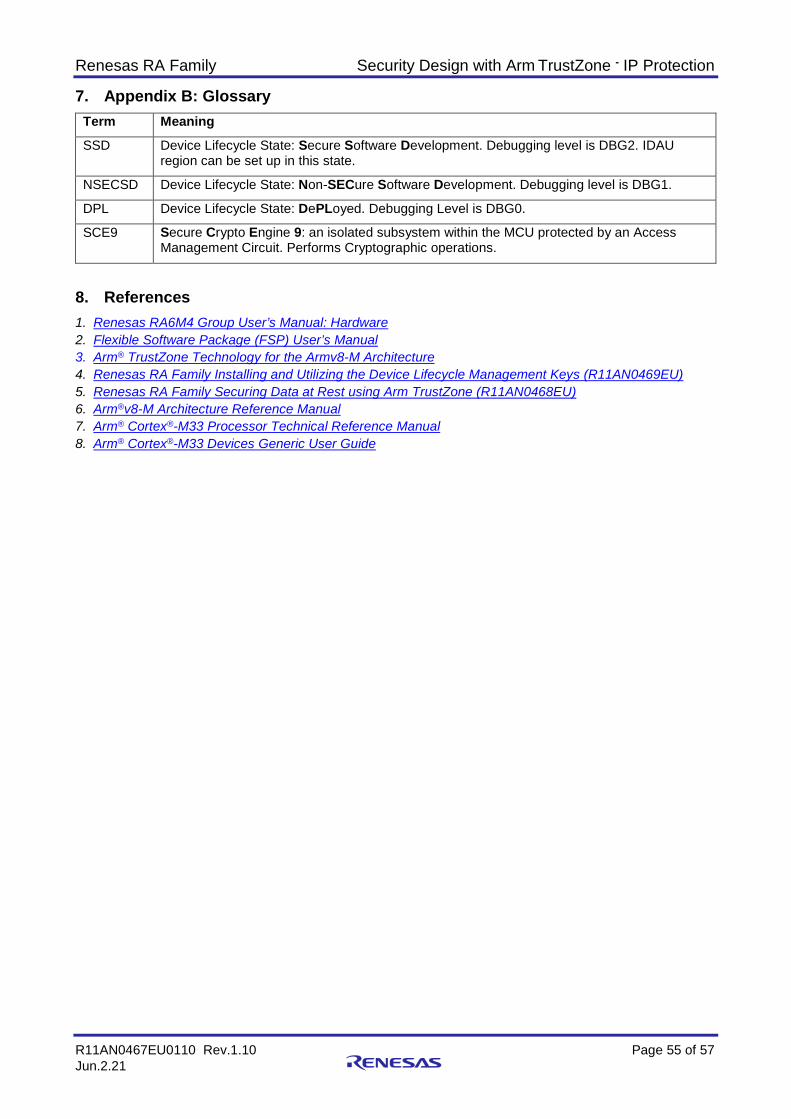
Renesas RA Family Security Design with Arm TrustZone - IP Protection
R11AN0467EU0110 Rev.1.10 Page 55 of 57 Jun.2.21
7. Appendix B: Glossary Term Meaning
SSD Device Lifecycle State: Secure Software Development. Debugging level is DBG2. IDAU region can be set up in this state.
NSECSD Device Lifecycle State: Non-SECure Software Development. Debugging level is DBG1.
DPL Device Lifecycle State: DePLoyed. Debugging Level is DBG0.
SCE9 Secure Crypto Engine 9: an isolated subsystem within the MCU protected by an Access Management Circuit. Performs Cryptographic operations.
8. References 1. Renesas RA6M4 Group User’s Manual: Hardware 2. Flexible Software Package (FSP) User’s Manual 3. Arm® TrustZone Technology for the Armv8-M Architecture 4. Renesas RA Family Installing and Utilizing the Device Lifecycle Management Keys (R11AN0469EU) 5. Renesas RA Family Securing Data at Rest using Arm TrustZone (R11AN0468EU) 6. Arm®v8-M Architecture Reference Manual 7. Arm® Cortex®-M33 Processor Technical Reference Manual 8. Arm® Cortex®-M33 Devices Generic User Guide
Renesas RA Family Security Design with Arm TrustZone - IP Protection
R11AN0467EU0110 Rev.1.10 Page 56 of 57 Jun.2.21
9. Website and Support Visit the following URLs to learn about the RA family of microcontrollers, download tools and documentation, and get support.
EK-RA6M4 Resources renesas.com/ra/ek-ra6m4 RA Product Information renesas.com/ra Flexible Software Package (FSP) renesas.com/ra/fsp RA Product Support Forum renesas.com/ra/forum Renesas Support renesas.com/support

Renesas RA Family Security Design with Arm TrustZone - IP Protection
R11AN0467EU0110 Rev.1.10 Page 57 of 57 Jun.2.21
Revision History
Rev. Date Description Page Summary
1.00 Oct.01.20 — Initial release 1.10 Jun.2.21 — Update to FSP v3.0.0 and remove usage instructions with E2

© 2021 Renesas Electronics Corporation. All rights reserved.
Notice 1. Descriptions of circuits, software and other related information in this document are provided only to illustrate the operation of semiconductor products
and application examples. You are fully responsible for the incorporation or any other use of the circuits, software, and information in the design of your product or system. Renesas Electronics disclaims any and all liability for any losses and damages incurred by you or third parties arising from the use of these circuits, software, or information.
2. Renesas Electronics hereby expressly disclaims any warranties against and liability for infringement or any other claims involving patents, copyrights, or other intellectual property rights of third parties, by or arising from the use of Renesas Electronics products or technical information described in this document, including but not limited to, the product data, drawings, charts, programs, algorithms, and application examples.
3. No license, express, implied or otherwise, is granted hereby under any patents, copyrights or other intellectual property rights of Renesas Electronics or others.
4. You shall not alter, modify, copy, or reverse engineer any Renesas Electronics product, whether in whole or in part. Renesas Electronics disclaims any and all liability for any losses or damages incurred by you or third parties arising from such alteration, modification, copying or reverse engineering.
5. Renesas Electronics products are classified according to the following two quality grades: “Standard” and “High Quality”. The intended applications for each Renesas Electronics product depends on the product’s quality grade, as indicated below. "Standard": Computers; office equipment; communications equipment; test and measurement equipment; audio and visual equipment; home
electronic appliances; machine tools; personal electronic equipment; industrial robots; etc. "High Quality": Transportation equipment (automobiles, trains, ships, etc.); traffic control (traffic lights); large-scale communication equipment; key
financial terminal systems; safety control equipment; etc. Unless expressly designated as a high reliability product or a product for harsh environments in a Renesas Electronics data sheet or other Renesas Electronics document, Renesas Electronics products are not intended or authorized for use in products or systems that may pose a direct threat to human life or bodily injury (artificial life support devices or systems; surgical implantations; etc.), or may cause serious property damage (space system; undersea repeaters; nuclear power control systems; aircraft control systems; key plant systems; military equipment; etc.). Renesas Electronics disclaims any and all liability for any damages or losses incurred by you or any third parties arising from the use of any Renesas Electronics product that is inconsistent with any Renesas Electronics data sheet, user’s manual or other Renesas Electronics document.
6. When using Renesas Electronics products, refer to the latest product information (data sheets, user’s manuals, application notes, “General Notes for Handling and Using Semiconductor Devices” in the reliability handbook, etc.), and ensure that usage conditions are within the ranges specified by Renesas Electronics with respect to maximum ratings, operating power supply voltage range, heat dissipation characteristics, installation, etc. Renesas Electronics disclaims any and all liability for any malfunctions, failure or accident arising out of the use of Renesas Electronics products outside of such specified ranges.
7. Although Renesas Electronics endeavors to improve the quality and reliability of Renesas Electronics products, semiconductor products have specific characteristics, such as the occurrence of failure at a certain rate and malfunctions under certain use conditions. Unless designated as a high reliability product or a product for harsh environments in a Renesas Electronics data sheet or other Renesas Electronics document, Renesas Electronics products are not subject to radiation resistance design. You are responsible for implementing safety measures to guard against the possibility of bodily injury, injury or damage caused by fire, and/or danger to the public in the event of a failure or malfunction of Renesas Electronics products, such as safety design for hardware and software, including but not limited to redundancy, fire control and malfunction prevention, appropriate treatment for aging degradation or any other appropriate measures. Because the evaluation of microcomputer software alone is very difficult and impractical, you are responsible for evaluating the safety of the final products or systems manufactured by you.
8. Please contact a Renesas Electronics sales office for details as to environmental matters such as the environmental compatibility of each Renesas Electronics product. You are responsible for carefully and sufficiently investigating applicable laws and regulations that regulate the inclusion or use of controlled substances, including without limitation, the EU RoHS Directive, and using Renesas Electronics products in compliance with all these applicable laws and regulations. Renesas Electronics disclaims any and all liability for damages or losses occurring as a result of your noncompliance with applicable laws and regulations.
9. Renesas Electronics products and technologies shall not be used for or incorporated into any products or systems whose manufacture, use, or sale is prohibited under any applicable domestic or foreign laws or regulations. You shall comply with any applicable export control laws and regulations promulgated and administered by the governments of any countries asserting jurisdiction over the parties or transactions.
10. It is the responsibility of the buyer or distributor of Renesas Electronics products, or any other party who distributes, disposes of, or otherwise sells or transfers the product to a third party, to notify such third party in advance of the contents and conditions set forth in this document.
11. This document shall not be reprinted, reproduced or duplicated in any form, in whole or in part, without prior written consent of Renesas Electronics. 12. Please contact a Renesas Electronics sales office if you have any questions regarding the information contained in this document or Renesas
Electronics products.
(Note1) “Renesas Electronics” as used in this document means Renesas Electronics Corporation and also includes its directly or indirectly controlled subsidiaries.
(Note2) “Renesas Electronics product(s)” means any product developed or manufactured by or for Renesas Electronics.
(Rev.4.0-1 November 2017)
Corporate Headquarters Contact information TOYOSU FORESIA, 3-2-24 Toyosu, Koto-ku, Tokyo 135-0061, Japan www.renesas.com
For further information on a product, technology, the most up-to-date version of a document, or your nearest sales office, please visit: www.renesas.com/contact/.
Trademarks Renesas and the Renesas logo are trademarks of Renesas Electronics Corporation. All trademarks and registered trademarks are the property of their respective owners.