removing the primary system memory (ram) - eurocom · removing the primary system memory ... and...
TRANSCRIPT

Disassembly
Removing the Primary System Memory (RAM) 2 - 11
2.Disassem
bly
Removing the Primary System Memory (RAM) The computer has four memory sockets for 204 pin Small Outline Dual In-line (SO-DIMM) DDR III (DDR3) type memorymodules. The total memory size is automatically detected by the POST routine once you turn on your computer.
Note that four SO-DIMMs are only supported by Quad-Core CPUs; Dual-Core CPUs support two SO-DIMMs maxi-mum.
Two primary memory sockets are located under component bay cover (the bottom case cover), and two secondarymemory sockets are located under the keyboard (not user upgradable). If you are installing only two RAM modulesthen they should be installed in the primary memory sockets under the component bay cover.
Note that the RAM located under the keyboard is not user upgradable. Contact your service center for more information if youwish to upgrade the memory in the secondary memory sockets.
Memory Upgrade Process1. Turn off the computer, and turn it over, remove the battery (page 2 - 5).2. Remove screws - (Figure 7a). 3. Slide the bottom cover until the cover and case indicators are aligned (Figure 7b).
Figure 7 RAM Module
Removal
a. Remove the screws.b. Slide the bottom
cover until the coverand case indicatorsare aligned.
1 45
• 4 Screws
a.
21 4
3
b.
55
Disassembly
2 - 12 Removing the Primary System Memory (RAM)
2.D
isas
sem
bly
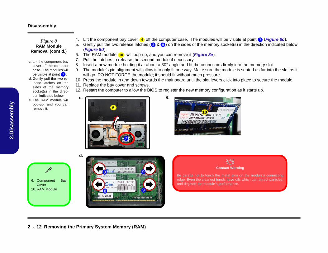
4. Lift the component bay cover off the computer case. The modules will be visible at point (Figure 8c).5. Gently pull the two release latches ( & ) on the sides of the memory socket(s) in the direction indicated below
(Figure 8d).6. The RAM module will pop-up, and you can remove it (Figure 8e).7. Pull the latches to release the second module if necessary.8. Insert a new module holding it at about a 30° angle and fit the connectors firmly into the memory slot.9. The module’s pin alignment will allow it to only fit one way. Make sure the module is seated as far into the slot as it
will go. DO NOT FORCE the module; it should fit without much pressure.10. Press the module in and down towards the mainboard until the slot levers click into place to secure the module.11. Replace the bay cover and screws.12. Restart the computer to allow the BIOS to register the new memory configuration as it starts up.
66 7Figure 8RAM Module
Removal (cont’d.)
c. Lift the component baycover off the computercase. The modules willbe visible at point .
d. Gently pull the two re-lease latches on thesides of the memorysocket(s) in the direc-tion indicated below.
e. The RAM module willpop-up, and you canremove it.
7
6. Component BayCover
10. RAM Module
8 9
10
d.
c.
7
8
e.
9
Contact Warning
Be careful not to touch the metal pins on the module’s connectingedge. Even the cleanest hands have oils which can attract particles,and degrade the module’s performance.
610
9
8
Disassembly
Removing the System Memory (RAM) from Under the Keyboard 2 - 13
2.Disassem
bly
Removing the System Memory (RAM) from Under the KeyboardThe computer has four memory sockets for 204 pin Small Outline Dual In-line (SO-DIMM) DDR III (DDR3) type memorymodules. The total memory size is automatically detected by the POST routine once you turn on your computer.
Note that four SO-DIMMs are only supported by Quad-Core CPUs; Dual-Core CPUs support two SO-DIMMs maxi-mum.
Two primary memory sockets are located under component bay cover (the bottom case cover), and two secondarymemory sockets are located under the keyboard. If you are installing only two RAM modules then they should be in-stalled in the primary memory sockets under the component bay cover.
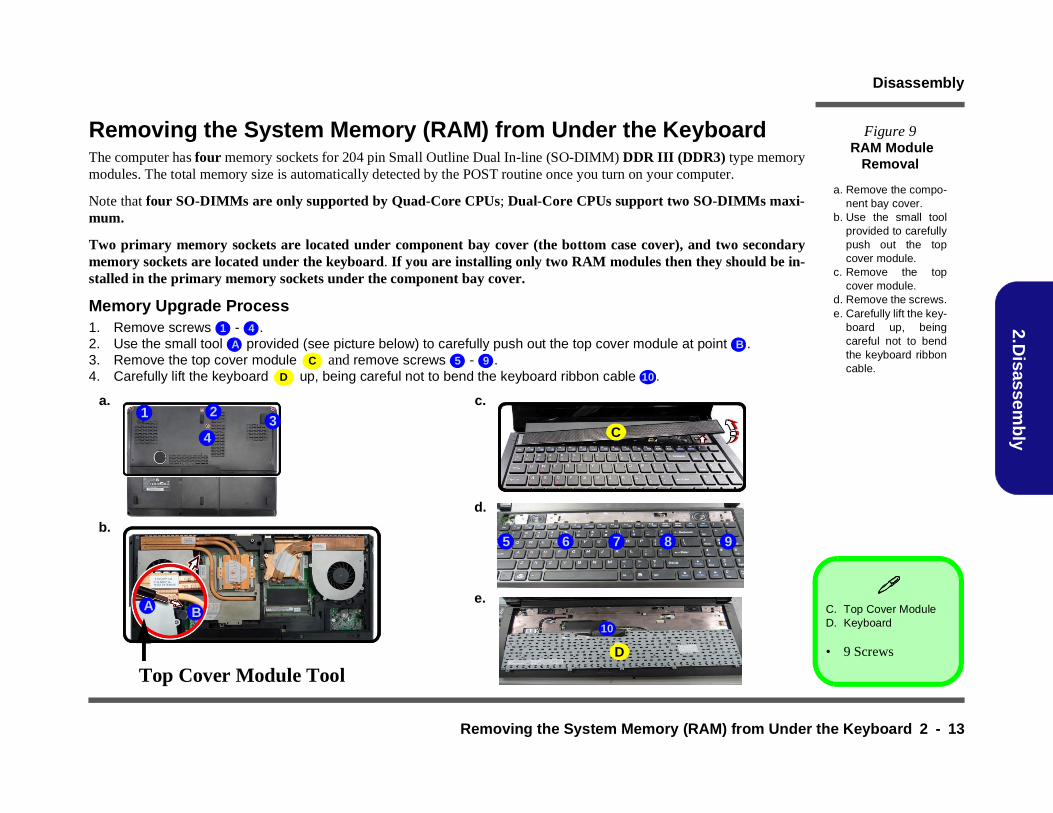
Memory Upgrade Process1. Remove screws - .2. Use the small tool provided (see picture below) to carefully push out the top cover module at point .3. Remove the top cover module and remove screws - . 4. Carefully lift the keyboard up, being careful not to bend the keyboard ribbon cable .
Figure 9 RAM Module
Removal
a. Remove the compo-nent bay cover.
b. Use the small toolprovided to carefullypush out the topcover module.
c. Remove the topcover module.
d. Remove the screws.e. Carefully lift the key-
board up, beingcareful not to bendthe keyboard ribboncable.
1 4A B
C 5 9D 10
C. Top Cover ModuleD. Keyboard
• 9 Screws
a. c.
C
A
Top Cover Module Tool
B
d.
965 87
e.
D
b.
21
43
10

Disassembly
2 - 14 Removing the System Memory (RAM) from Under the Keyboard
2.D
isas
sem
bly
5. Disconnect the keyboard ribbon cable from the locking collar socket by using a small flat-head screwdriver to pry the locking collar pins away from the base. (Figure 10c).
6. Remove the keyboard and the memory sockets & will be visible.7. Gently pull the two release latches ( & ) on the sides of the memory socket(s) in the direction indicated below.8. The RAM module will pop-up, and you can remove it.9. Pull the latches to release the second module if necessary.10. Insert a new module holding it at about a 30° angle and fit the connectors firmly into the memory slot.11. The module’s pin alignment will allow it to only fit one way. Make sure the module is seated as far into the slot as it
will go. DO NOT FORCE the module; it should fit without much pressure.12. Press the module in and down towards the mainboard until the slot levers click into place to secure the module.13. Replace the bay cover and screws.14. Restart the computer to allow the BIOS to register the new memory configuration as it starts up.
10 11 12
g.
f.
13
12
h.
10
11 12
17
17
Contact Warning
Be careful not to touch the metal pins on the module’sconnecting edge. Even the cleanest hands have oilswhich can attract particles, and degrade the module’sperformance.
14
15 16
15 16
Figure 10RAM Module
Removal (cont’d.)
f. Disconnect the key-board ribbon cablefrom the locking collarsocket by using a smallflat-head screwdriverto pry the locking collarpins away from thebase.
g. Remove the keyboardand the memory sock-ets will be visible.
h. Gently pull the two re-lease latches on thesides of the memorysocket(s) in the direc-tion indicated below.
17. RAM Modules
13 1415 16
17

Disassembly
Removing the MSATA Module 2 - 19
2.Disassem
bly
Removing the MSATA Module1. Turn off the computer, remove the battery (page 2 - 5), and component bay cover (page 2 - 11).2. Locate the module, it is visible at point (Figure 15a).3. Carefully disconnect the cable and remove the screw from the module (Figure 15b).4. Lift the module up and off the computer (Figure 15b).
Figure 15 MSATA Module
Removal
a. Remove the screw.b. Disconnect the cable and
remove the screw.c. Lift the 3G module up off
the socket.
12 3
4
a.
b.
1
4
2
3
4
c.
d.
4. 3G Module
• 1 Screw