removing salt from coal mine wastewater in a remote, … · removing salt from coal mine wastewater...
TRANSCRIPT
Removing Salt From Coal Mine Wastewater in a Remote, Wet Area: Full Scale Experience
Srikanth Muddasani, P.E. Veolia Water Technologies, USA

• Centralized ZLW treatment facility to handle water from six mine locations
• All six mines located within Monongahela River Basin
• Regulatory driver = Chlorides to < 218 mg/L
• Solid wastes generated are disposed in on-site landfill
• Treated effluent is discharged to creek and/or used as frac water
Project Background
2

Contributing Mine Locations
18” Force Main collects water from 4 mines to the North
14” Force Main collects water from 2 mines to the South
CENTRALIZED TREATMENT FACILITY

• Centralized ZLW treatment facility is designed to treat 5 MGD (795 m3/h) of mine water
• Mine water, pretreated for metals removal where needed, conveyed from six source points to the facility through 32 miles of pipeline
• Executed through a Design-Build-Operate contract with Veolia
• June 2010 - Request for proposals issued
• April 2011 - Project awarded
• July 2011 - Construction began
• May 2013 - Full operation
The Project
4

Note 1: Average Value based on the data collected between Jun 1st 2014 to Dec 31st 2014 Note 2: Average Value based on the data collected between Aug 20th,2014 to Sep 5th, 2014
Design Basis - Influent Mine Water
5
Parameters Original Design Current Design1
Design Flow, gpm 3500 (795 m3/h) 2026 (460 m3/h)
pH, S.U. 5 - 10 7.39
Temperature, deg F 38 – 85 (3 – 30 deg C) 60 – 72 (15-22 deg C)
Calcium, mg/L 300 217
Magnesium, mg/L 200 104
Iron, mg/L 150 0.27
Manganese, mg/L 2 0.27
Alkalinity, mg/L CaCO3 700 - 1200 891
Sulfate, mg/L 5,500 2700 2
Chloride, mg/L 1,500 1530 2
TDS, mg/L 10,000 8600
Silica, mg/L as SiO2 10 10

Note 1: Applied to product water prior to remineralization
Effluent Water Quality Requirements
6
Parameters Maximum Effluent Concentration
Chlorides, mg/L < 218
TDS, mg/L < 150 1
pH, S.U. 6 to 9
Minimum Hardness, mg/l as CaCO3 ≥ 50

• Raw Water Pretreatment System
• Reverse Osmosis System
• Thermal Brine Management System
The Process: Three Primary Components
7

Process Overview
8
Primary Objectives 1. Remove TDS and Chlorides 2. Zero Liquid Waste

Facility Overview
9
Evaporator
Crystallizer
RO Trains
Raw Water Tank
Multimedia Filters Lime & Soda Ash Silos
Softening System
1st Stage Clarifier
Dewatering Building
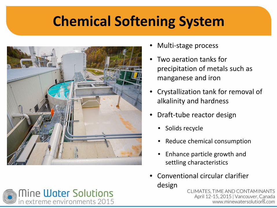
• Multi-stage process
• Two aeration tanks for precipitation of metals such as manganese and iron
• Crystallization tank for removal of alkalinity and hardness
• Draft-tube reactor design
• Solids recycle
• Reduce chemical consumption
• Enhance particle growth and settling characteristics
• Conventional circular clarifier design
Chemical Softening System
10
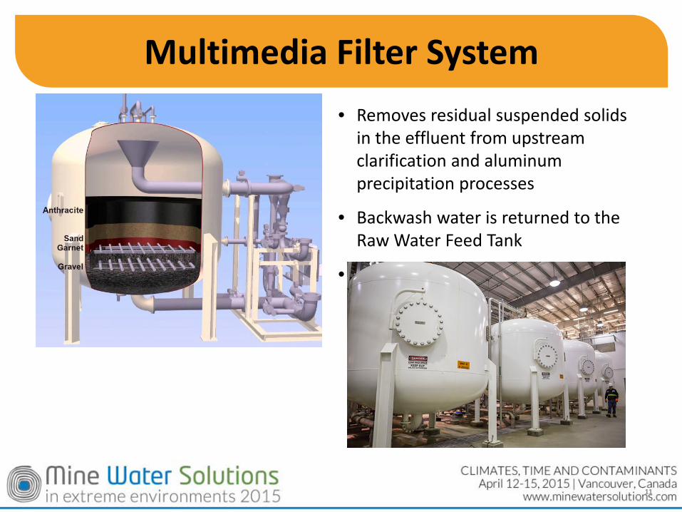
• Removes residual suspended solids in the effluent from upstream clarification and aluminum precipitation processes
• Backwash water is returned to the Raw Water Feed Tank
• Filtrate is conveyed to the RO System
Multimedia Filter System
11
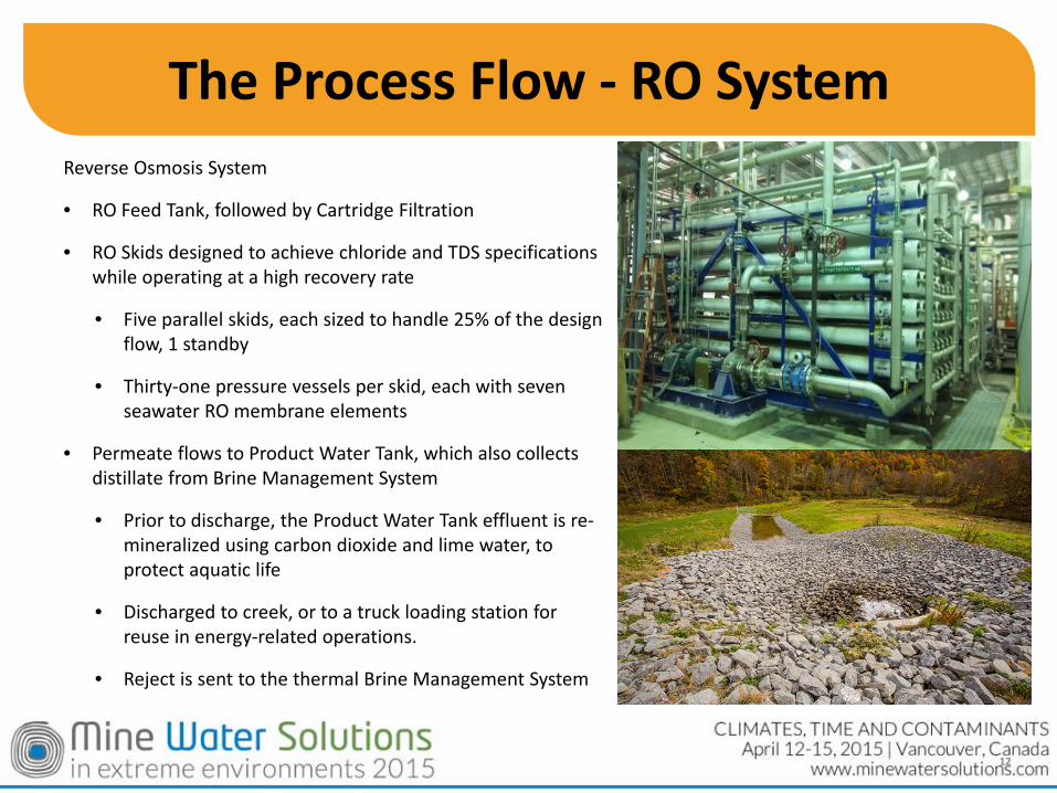
Reverse Osmosis System
• RO Feed Tank, followed by Cartridge Filtration
• RO Skids designed to achieve chloride and TDS specifications while operating at a high recovery rate
• Five parallel skids, each sized to handle 25% of the design flow, 1 standby
• Thirty-one pressure vessels per skid, each with seven seawater RO membrane elements
• Permeate flows to Product Water Tank, which also collects distillate from Brine Management System
• Prior to discharge, the Product Water Tank effluent is re-mineralized using carbon dioxide and lime water, to protect aquatic life
• Discharged to creek, or to a truck loading station for reuse in energy-related operations.
• Reject is sent to the thermal Brine Management System
The Process Flow - RO System
12

Evaporator
• Concentric falling film unit is divided into two sections with a low concentration side and a high concentration side
• Split design to reduce overall power consumption by allowing a portion of the evaporation to occur at a lower boiling point rise than the final concentration
• Evaporator operates as a Mechanical Vapor Recompression System
• Recycle of hot vapor in the system; minimize auxiliary steam
• Distillates from the Evaporator and Crystallizer are pumped through a Feed Preheater for heat transfer to the incoming brine
• Heat exchanger for efficient energy utilization
Evaporation
13

• Crystallizer includes a vapor body, recirculation pump, and forces circulation heat exchanger
• Vapors created by concentrating the slurry in the Crystallizer are recompressed and recirculated through the heater
• As the brine concentration increases, the solution becomes supersaturated and salts precipitate, resulting in a brine slurry
• A slip stream of the crystallizer slurry is sent to centrifuges for dewatering
• The result: Zero Liquid Waste
• Dewatered salt cake is disposed in the on-site landfill along with the dewatered sludge from the softening processes
Crystallization
14

Thermal Brine Management System
15
Crystallizer Evaporator Heat Exchanger
Distillate Tank
Crystallizer
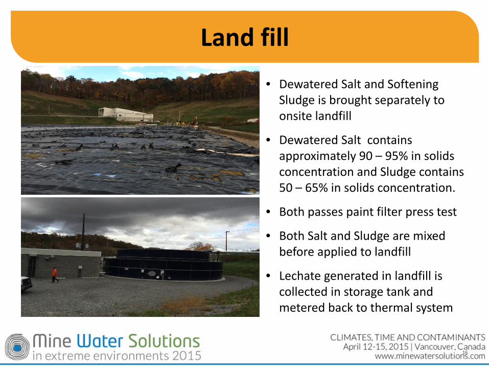
• Dewatered Salt and Softening Sludge is brought separately to onsite landfill
• Dewatered Salt contains approximately 90 – 95% in solids concentration and Sludge contains 50 – 65% in solids concentration.
• Both passes paint filter press test
• Both Salt and Sludge are mixed before applied to landfill
• Lechate generated in landfill is collected in storage tank and metered back to thermal system
Land fill
16
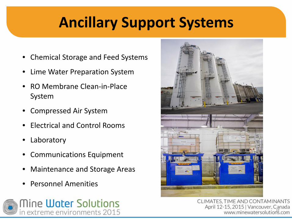
• Chemical Storage and Feed Systems
• Lime Water Preparation System
• RO Membrane Clean-in-Place System
• Compressed Air System
• Electrical and Control Rooms
• Laboratory
• Communications Equipment
• Maintenance and Storage Areas
• Personnel Amenities
Ancillary Support Systems
17

Feed Water Conductivity
18
0
2,000
4,000
6,000
8,000
10,000
12,000
14,000
16,000
18,000
06/01/14 07/06/14 09/16/14 10/21/14 11/25/14 12/31/14
Cond
uctiv
ity (µ
s/cm
)
Days
Current Feed Conductivity Design Feed Conductivity
Original Design Conductivity = 13,000 µs/cm Current Avg Conductivity = 11,180 µs/cm

Product Water Conductivity
19
Product water Cond before Remineralization = 63 µs/cm Final Effluent Discharge Cond = 142 µs/cm
0
20
40
60
80
100
120
140
160
180
200
06/01/14 07/06/14 09/16/14 10/21/14 11/25/14 12/31/14
Cond
uctiv
ity (µ
s/cm
)
Days
Product Water Cond before Remin Final Eff Discharge Cond

Feed Water Chlorides
20
1400
1450
1500
1550
1600
1650
8/20/14 8/22/14 8/26/14 8/28/14 9/1/14 9/2/14 9/3/14 9/4/14 9/5/14
Chlo
rides
(mg/
L)
Days
Current Feed Chlorides
Current Avg Feed Chlorides = 1,530 mg/l

Final Effluent Chlorides
21
0.00
5.00
10.00
15.00
20.00
25.00
1/1/2014 1/21/2014 2/10/2014 3/2/2014 3/22/2014 4/11/2014 5/1/2014 5/21/2014 6/10/2014
Efflu
ent C
hlor
ides
, mg/
l
Days
Final Effluent Chlorides = 16 mg/l

Please Note: Waste Estimation for design condition was estimated based on 3500 gpm flow Waste Estimation for Current Average Condition was estimated based on 2026 gpm flow
Estimated Waste Generation
22
Waste Design Condition Current Average Condition
Softening Sludge (on a 100% dry basis) 6,666 lb/hr (3,030 kg/hr) 2,200 lb/hr (1,000 kg/hr)
Salt (on a 100% dry basis) 17,500 lb/hr (7,954 kg/hr) 8,710 lb/hr (3,960 kg/hr)
Total Waste Generated (on 100% dry basis) 24,166 lb/hr (10,984 kg/hr) 10,910 lb/hr (4,960 kg/hr)

• Treatment process achieves > 99% removal of chlorides using state-of-the-art membrane technology
• Energy efficient evaporation and crystallization technology for brine management
• Solid waste generated onsite is disposed into onsite landfill and leachate generated at the landfill is sent back to the facility’s thermal treatment process
• Since no liquid waste leaves the property, this facility is termed as a “zero liquid waste” (ZLW) facility
Summary
23
Thank You!