removal action work plan€¦ · removal action work plan removal of lead-based paint from...
TRANSCRIPT

Prepared for
United States Department of the Interior Fish and Wildlife Service
911 NE 11th Avenue Portland, Oregon 97232
REMOVAL ACTION WORK PLAN
REMOVAL OF LEAD-BASED PAINT FROM STRUCTURES AND LEAD-CONTAMINATED SOIL MIDWAY ATOLL NATIONAL WILDLIFE REFUGE
MIDWAY ISLAND CONTRACT NO. F11PC00327
Prepared by
NW Demolition and Environmental, A Joint Venture
P.O. Box 230819 Tigard, Oregon 97281
29 February 2012
Removal Action Work Plan Removal of Lead-Based Paint from
Structures and Lead-Contaminated Soil Midway Atoll National Wildlife Refuge
Midway Island Contract No. F11PC00327
Prepared for
U.S. Fish and Wildlife Service 911 NE 11th Avenue
Portland, Oregon 97232
Attention: MaryAnn Amann
Prepared by
NW Demolition and Environmental, A Joint Venture P.O. Box 230819
Tigard, Oregon 97281 503-638-6900
Darin Leibelt Richard Wayper Project Manager Program Manager
29 February 2012

NW Demolition and Environmental,
A Joint Venture
ii 2/29/2012
TABLE OF CONTENTS
1. INTRODUCTION ................................................................................................ 1 1.1 Activity Summary........................................................................................ 1
2. HEALTH AND SAFETY ..................................................................................... 4
3. ENVIRONMENTAL PROTECTION .................................................................. 5 3.1 Equipment Operation and Management ...................................................... 5 3.2 Protection of Environmental Resources ...................................................... 6
3.2.1 Protection of Land Resources ......................................................... 6 3.2.2 Protection of Air Resources ............................................................ 7 3.2.3 Protection of Water Resources ........................................................ 7 3.2.4 Protection of Wildlife Resources .................................................... 7 3.2.5 Preservation and Protection of Historical, Archaeological, and Cultural Resources ...................................................................................... 8
4. ON-SITE WASTE MANAGEMENT .................................................................. 9 4.1 Demolition Debris ....................................................................................... 9 4.2 General Office Waste .................................................................................. 9 4.3 Waste Generate From a Spill ....................................................................... 9
5. LEAD-BASED PAINT ABATEMENT AND RE-PAINTING ......................... 11 5.1 Lead-Based Paint Abatement .................................................................... 11
5.1.1 Work Area Preparation ................................................................. 11 5.1.2 Lead Based Paint Removal ........................................................... 11 5.1.3 Painting ......................................................................................... 12 5.1.4 Cleanup and Waste Management .................................................. 14
5.2 Quality Assurance...................................................................................... 15
6. ASBESTOS CONTAINING MATERIALS REMOVAL .................................. 16 6.1 Sequence of Asbestos-Related Work ........................................................ 16
6.1.1 Work Area Preparation ................................................................. 16 6.1.2 Removal of Asbestos-Containing Materials ................................. 17
6.2 Air Monitoring ........................................................................................... 17

NW Demolition and Environmental,
A Joint Venture
iii 2/29/2012
6.3 Respiratory Protection Program ................................................................ 18 6.4 Decontamination ........................................................................................ 18 6.5 Clean-Up Verification Procedures ............................................................. 18 6.6 Waste Management ................................................................................... 19
7. DEMOLITION ................................................................................................... 20 7.1 General Demolition ................................................................................... 20 7.2 AST Demolition ........................................................................................ 21 7.3 Waste Management ................................................................................... 21
7.3.1 Clean Structural and Vegetative Wood Wastes ............................ 21 7.3.2 Metal Demolition Debris............................................................... 21 7.3.3 Concrete and Asphalt Demolition Debris ..................................... 22 7.3.4 Demolition Debris with Lead Containing Paint Firmly Intact ...... 22
8. SOIL EXCAVATION AND TREATMENT ..................................................... 23 8.1 Pre-Treatment Barrier Installation ............................................................. 23 8.2 Soil Excavation .......................................................................................... 23 8.3 MAECTITE® Reagent Application .......................................................... 25 8.4 Excavation Confirmation Sampling .......................................................... 25 8.5 Witness Barrier Installation ....................................................................... 26 8.6 Backfilling ................................................................................................. 26 8.7 Erosion Protection ..................................................................................... 27
9. MANAGEMENT OF TREATED SOIL ............................................................ 28 9.1 General ....................................................................................................... 28 9.2 Containment Cell Design and Retrofit ...................................................... 29 9.3 Treatment Confirmation Sampling ............................................................ 31 9.4 Final Cover ................................................................................................ 31
10. QUALITY ASSURANCE .................................................................................. 32
11. PROJECT SCHEDULE AND REPORTING .................................................... 33
12. KEY PERSONNEL ............................................................................................ 34
13. BIBLIOGRPAHY............................................................................................... 39

NW Demolition and Environmental,
A Joint Venture
iv 2/29/2012
LIST OF TABLES
Table 1. Estimated Depths and Volumes of Excavations and Backfill
LIST OF FIGURES
Figure 1: Site Layout
Figure 2: Decision Unit 1 Layout
Figure 3: Decision Unit 2 Layout
Figure 4: Decision Unit 3 Layout
Figure 5: Decision Unit 4 Layout
Figure 6: Decision Unit 5 Layout
Figure 7: Decision Unit 5 Layout Continued
Figure 8: Decision Unit 6 Layout
Figure 9: Decision Unit 7 Layout
Figure 10: Decision Unit 8 Layout

NW Demolition and Environmental,
A Joint Venture
v 2/29/2012
LIST OF APPENDICES
Appendix A: Manufacturer’s Specifications
Appendix B: Field Sampling Plan
Appendix C: Quality Assurance Project Plan
Appendix D: Construction Quality Assurance Plan
Appendix E: Project Schedules

NW Demolition and Environmental,
A Joint Venture
1 2/29/2012
1. INTRODUCTION
NW Demolition and Environment (NWDE) has prepared this Removal Action Work Plan (RAWP) on behalf of the U.S. Fish and Wildlife Service (FWS) as part of its contract to complete the removal of Lead-Based Paint (LBP) from Structures and Lead-Contaminated Soil at Sand Island, Midway Atoll National Wildlife Refuge (Refuge or Site).
This RAWP provides a detailed discussion of NWDE’s approach to the completion of a Non-Time Critical Removal Action for the removal of lead-based paint from structures and lead-contaminated soil at Midway Atoll using FWS’ authority under the Comprehensive Environmental Response, Compensation, and Liability Act (CERCLA), beginning at U.S. Code volume 42 Sections 9604 and Federal Executive Order 12580. The removal action is to be completed in substantial accordance with CERCLA and the National Oil and Hazardous Substances Pollution Contingency Plan (NCP).
This RAWP covers the Removal Action including, but not limited to, lead abatement, demolition, excavation, and treatment of waste. The RAWP is one of the series of plans that will be used to describe the work to be done for the Removal Action. As such, the procedures described in the RAWP must be read in combination with the attached documents.
1.1 Activity Summary
A January 2011 Engineering Evaluation/Cost Analysis (EE/CA) (GeoEngineers, 2011) evaluated cleanup alternatives based on a cleanup goal of 75 milligrams per kilogram (mg/kg) for lead in soil. Of the alternatives evaluated, the U.S. Fish and Wildlife Service selected, in an Action Memorandum signed in July 2011, Alternative 3 of the EE/CA as the chosen method to complete the removal action in each of nine Decision Units (DU) (Figure 1). In general, the scope of work involves: 1) LBP removal from existing structures and re-painting using encapsulation paint; 2) asbestos containing materials (ACM) removal/treatment and demolition with off-site disposal; 3) excavation and on-site treatment and consolidation of lead-contaminated soil; and 4) demolition of several buildings and two above-ground oil storage tanks (AST). The excavated soils and demolition debris will be treated with MAECTITE®.
NWDE will use the existing R-2 unit (a former Naval Air Facility [NAF] freshwater treatment unit) for permanent internment of the stabilized waste materials. Design of the

NW Demolition and Environmental,
A Joint Venture
2 2/29/2012
final R-2 modifications is ongoing at the time of this document production and will be detailed in a future submittal in 2012.
The Removal Action will be conducted over multiple years while the majority of the birds are not present on the site. This period is generally July through October of each year. Work elements by year are as follows:
• 2011 – Placing Shade Cloth over the excavation areas in DU1, DU2 and DU6; and lead abatement of Buildings 349, 363, and 357 in DU6.
• 2012 – Design and construction of R-2 and removal actions for DU6 and DU1.
• 2013 – Removal action for DU2.
• 2014 – Removal action for DU4.
• 2015 – Removal actions for DU5 and DU7.
• 2016 – Removal actions for DU3 and DU8.
• 2017 – Removal action for DU9.
The planned removal actions identified in the EE/CA for each DU are summarized below:
• Decision Unit 1 (Figure 2) – Abatement of lead on Building 643 and the demolition of Buildings 619, 623, 626, and 628 with excavation of contaminated soils 50 feet out from the building footprints to a depth of 1 foot (ft.).
• Decision Unit 2 (Figure 3) – Removal of asbestos transite siding and the demolition of Buildings 578 and 579 with excavation of contaminated soils 30 feet out from the building footprints to a depth of 2 ft.
• Decision Unit 3 (Figure 4) – Abatement of lead on the exterior of Buildings 4203 and 4212. Excavation of contaminated soils 15 feet out from the building footprints of 4203, 4204, 4212, 415, 416, 417, 418, 419, 421, 422, 423, and 424 to a depth of 1 ft.
• Decision Unit 4 (Figure 5) – Abatement of lead on the exterior of Buildings 259, 2403, and 2404 with the excavation of contaminated soils 20 feet out from the building footprints to a depth of 3 ft.

NW Demolition and Environmental,
A Joint Venture
3 2/29/2012
• Decision Unit 5 (Figures 6 and 7) – Abatement of lead on the exterior of Buildings 5309 and 5303 with the excavation of contaminated soils 15 feet out from the building footprints to a depth of 1 ft.
• Decision Unit 6 (Figure 8) – Abatement of lead on the exterior of Buildings 393, 342, 356, 357, 353, 349, and 363 with the excavation of contaminated soils 50 feet out from the building footprints to a depth of 1 ft.
• Decision Unit 7 (Figure 9) – Abatement of lead on the exterior of Buildings 331, 3504, 3502, 3503, and 3512 with the excavation of contaminated soils 50 feet out from the building footprints to a depth of 2 ½ ft.
• Decision Unit 8 (Figure 10) – Decommissioning of each AST by removal with excavation of contaminated soils within the containment berms to a depth of ½ ft.
• Decision Unit 9 – Abatement of lead on the exterior of the remaining structures with exterior lead-based paint such as storage buildings, pump house, lift stations and other ancillary structures (except for the above ground water tanks near the runway) and the excavation of approximately 6,000 cubic yards of contaminated soils.
The anticipated depths of excavation described are based on data evaluation and the subsequent risk assessment completed in the EE/CA and are the estimated excavation depths necessary to remove all soil containing lead at concentrations above the PCG. However, confirmation sampling (Section 8.4) will be conducted to confirm adequate removal and if necessary, additional excavation may be conducted. Details of the work components are provided in the following sections.

NW Demolition and Environmental,
A Joint Venture
4 2/29/2012
2. HEALTH AND SAFETY
A site-specific Health and Safety Plan (HASP) has been prepared and submitted under separate cover and is intended to comply with the requirements of the Occupational Safety and Health Administration (OSHA) – 29 Code of Federal Regulations (CFR) 1910 Subpart I, 1910 Subpart Z (lead). The HASP consists of a site specific Accident Prevention Plan (APP) and a detailed Task Hazard Analysis (THA) for each activity. The HASP is been prepared and submitted under separate cover.
NWDE will comply will all safety and occupational health requirements per OSHA 29 CFR 1910 Subpart I, 1910 Subpart Z (lead), as well as all other applicable Federal, state, local, and host installation laws, ordinances, regulations, and policies. While engaged in site work, NWDE employees, subcontractors, agents, representatives, clients and affiliations will have access to these plans and be made aware of chemical or physical risk exposure associated with work as well as their respective responsibilities.

NW Demolition and Environmental,
A Joint Venture
5 2/29/2012
3. ENVIRONMENTAL PROTECTION
This section describes the relevant procedures for protection of land, air, water, historical, and wildlife resources during removal action activities.
3.1 Equipment Operation and Management
The following equipment (or similar) will be utilized for soil remediation activities:
• Ford F-350 Service Truck
• CAT 308 Excavator
• Volvo 290 Excavator
• Bobcat S-185 Skid Steer
• Volvo A30D Off-Road Truck
The transportation of soil, seeds, plants, insects, or animals to the Refuge is not allowed to avoid the introduction of invasive species. As such, equipment brought to the Refuge will be pressure-washed prior to transport to the Refuge. FWS representatives will be provided the opportunity to inspect and approve the cleanliness of the equipment in Honolulu prior to departure, and upon arrival on Midway.
While operating on site, heavy equipment will be limited to the island speed limit of 10 mph. Equipment operators are required to check for birds under each tire before moving a vehicle. All equipment will be equipped with a working light at night to avoid impacts to wildlife.
Equipment and vehicles will be monitored over the course of the project and kept in proper operating condition to minimize emissions. Equipment will be shut down when not in use. Frequent visual checks will be made for possible oil leaks/spills, and if found, immediate appropriate action, including reporting, will be taken.
Sound and noise pollution will be kept under surveillance and control to minimize damage to the environment by noise. All equipment used in this work will be equipped with satisfactory mufflers and sound abatement devices to reduce engine noise.

NW Demolition and Environmental,
A Joint Venture
6 2/29/2012
3.2 Protection of Environmental Resources
3.2.1 Protection of Land Resources
In accordance with the Midway Atoll NWR Visitor Information Guidelines, the following restrictions apply to work on the Refuge:
• Runways are closed except for designated crossing areas.
• Personnel will remain on roads and trails to avoid impacting burrowing seabirds.
• Closed beaches (see map) will be avoided at all times.
• Personnel will remain at least 150 feet from wetlands and endangered and threatened species (Monk Seals, Short-tailed Albatross, Green Sea Turtles, and Laysan Ducks).
• Collection and/or removal of wildlife parts and historical artifacts from the Refuge are prohibited.
• Refuge Staff will be notified immediately if unexploded ordinance are discovered.
• All glass, aluminum, and plastic waste generated during the work will be collected and stored for removal from the Refuge and recycling.
• No soil, seeds, plants, insects, or animals will knowingly be transported to the Refuge.
No removal, cutting, defacing, injury, or destruction to any land resources, including trees, shrubs, vines, grasses, topsoil and landforms, outside the designated work zones will occur without permission from a FWS designated representative. The work zone includes access to buildings proposed for abatement and/or demolition and soil removal areas. In addition, a 15-foot perimeter around the excavation areas will be designated as a work zone.
No ropes, cables, or guys will be fastened or attached to any trees for anchorage unless specifically authorized.
Erosion control structures and procedures will be implemented prior to excavation activities as detailed in the approved Soil and Sediment Erosion Control Plan, which has been prepared and submitted under separate cover.

NW Demolition and Environmental,
A Joint Venture
7 2/29/2012
The transportation of soil, seeds, plants, insects, or animals to the Refuge is not allowed and as such, all cargo, luggage, clothing, and shoes will be clean. Specially, the following protocol will be completed prior to arrival at the island:
• The bottoms of shoes will be scrubbed with a brush and soapy water.
• Shoes will be unlaced to make sure no seeds are trapped.
• Socks will be checked carefully for trapped seeds.
• Backpacks will be turned inside out to remove all seeds and washed.
• The bottom of luggage will be checked for seeds.
3.2.2 Protection of Air Resources
Asbestos abatement activities will be kept under surveillance at all times in accordance with the Asbestos Removal and Disposal Work Plan prepared and submitted under separate cover. Burning of trash on site will only be permitted at designated areas and only be performed by Refuge personnel. All equipment will be properly maintained and tuned for efficiency to minimize emissions.
3.2.3 Protection of Water Resources
Vehicles and equipment will be inspected daily and immediately taken out of service in the event of leaks. Cans containing fuels or oils will be labeled and stored appropriately. In the event on-site equipment maintenance is required, precautions such as buckets and plastic sheeting will be used to ensure contaminants are not released to the environment.
3.2.4 Protection of Wildlife Resources
Numerous avian species reside at the Refuge. Demolition and excavation activities will occur from July to November to avoid the nesting seasons for most of the species. However, LBP abatement may overlap with the nesting seasons. The species listed below require special attention, along with measures for their protection:
Laysan and Black-Footed Albatross – Laysan Albatross are the most abundant species of bird found at the Refuge. They nest on the ground on almost any non-paved surface and return to the same nesting sites annually. The Laysan and Black-Footed
NW Demolition and Environmental,
A Joint Venture
8 2/29/2012
Albatross breed each November and egg laying continues until mid-December. Chicks hatch from late January through February and fledge in mid-June through late July.
Bonin Petrels – Bonin Petrels return to the Refuge in August to excavate burrows for their nests, which can be 5 to 8 feet long and three feet deep. Egg laying begins in January and continues through March. The first eggs hatch in February through April and the fledged chicks and adults leave the Refuge by late June and early July.
Laysan Duck – The Laysan Duck has been federally listed as endangered since 1967. On Midway Atoll, the ducks use the following habitats: upland vegetation, ephemeral wetlands, freshwater seeps, mudflats, and coastal areas. The Laysan Duck nesting season runs from February and November; however, most eggs are laid between April and August. Nests are built on the ground under thick vegetation, especially bunchgrass.
Equipment used during abatement operations will generally be operated on designated roads to avoid impact to birds. Where equipment will be required to go off-road, an area survey will be conducted by NWDE to identify occupied nests or burrows. If an occupied nest or burrow is discovered within the proposed transportation route, a new route will be identified or the nest and occupants relocated by trained personnel.
Lastly, the collection of live or dead wildlife parts; including but not limited to feathers, bones, eggs, shells or coral is prohibited.
3.2.5 Preservation and Protection of Historical, Archaeological, and Cultural Resources
Archeological oversight will be provided by 3rd party contractor (under contract to FWS) for all work completed in DU1. The contractor will be on-site during DU1 soil excavation work and will be tasked with performing the collection and cataloging of any artifacts. Care will be taken to protect in-place historical resources and immediately report to the Refuge (or Deputy) Manager any historical, archaeological items or skeletal remains encountered during field activities. Upon discovery, work will stop in the immediate area of the discovery until directed by the FWS to resume work. NWDE will notify the FWS if and when archeological significant items are encountered. NWDE will note the date, location and depth that the item was found. NWDE will take a photograph of the item as well and provide all documentation to the FWS within two days of its discovery.

NW Demolition and Environmental,
A Joint Venture
9 2/29/2012
4. ON-SITE WASTE MANAGEMENT
Management of waste generated as part of the specific work components such as LBP abatement, ACM abatement, demolition, and treated soils are described in Sections 5, 6, 7, and 8, respectively. Management of decontamination water associated with personal protective equipment is addressed in the HASP. Management of wastes from other streams is described below.
4.1 Demolition Debris
Demolition debris will be separated and managed as follows:
• Unpainted wood and unpainted concrete – stockpiled at a location mutually agreed upon between NWDE and FWS. These materials have the potential to be recycled on site upon future direction from FWS. The process of recycling these materials is not currently in the scope of work.
• Painted wood and painted concrete – will be hauled to the R-2 Unit and treated with MAECTITE.
• Steel - stockpiled at a location mutually agreed upon between NWDE and FWS, possibly the existing “bone yard” immediately east of the Seaplane hangar. Steel will be transported to metal recycler upon project completion.
• Asbestos-containing materials – will be packed into appropriate containers and barged off site upon project completion.
4.2 General Office Waste
All office type waste generated from project management activities will be reused or recycled to its greatest extent possible and disposed of within similar waste streams currently on Site. Waste that cannot be handled this way will be disposed of along with the Refuge’s general trash waste stream.
4.3 Waste Generate From a Spill
A small-scale spill of MAECTITE®, LeadStop® or other paint product will be handled consistent with the spilled product’s MSDS (see Appendix A).
A fuel or hydraulic oil leak or spill will be absorbed and collected with an absorbing product (i.e. “kitty-litter” type material or oil absorbing pads). Waste generated from

NW Demolition and Environmental,
A Joint Venture
10 2/29/2012
absorbing or cleaning up a spill will be containerized, and managed in accordance with facilities’ Spill Prevention, Control and Countermeasures Plan (SPCC) (GeoEngineers, 2009).

NW Demolition and Environmental,
A Joint Venture
11 2/29/2012
5. LEAD-BASED PAINT ABATEMENT AND RE-PAINTING
This section describes the procedures to be used for: 1) demolition of buildings that contain LBP; 2) cleanup of LBP chips generated during demolition work and paint removal; and 3) demolition of buildings, including complete building structures, concrete walls, wood frames, rafters, joists, concrete slabs and footings. The buildings that contain LBP but are not scheduled for demolition will be repainted.
5.1 Lead-Based Paint Abatement
5.1.1 Work Area Preparation
Lead warning signs will be posted at each entrance to the LBP removal work area. All signs will be in accordance with 29 CFR 1926. 62 and HIOSH 12-148.1. Clearly labeled “Lead Danger” tape will be used to maintain a 20 foot radius from the entrance to the work area. The LBP removal work area will be monitored by the Supervisor/Competent Person and Workers, in addition to use of barrier tape and posted signs, to ensure there is no unauthorized entry into the area.
5.1.2 Lead Based Paint Removal
Lead-containing paint will be removed and will be handled in such a manner to be disturbed as little as possible. Torch burning, dry scraping, and conventional power tools are prohibited.
Procedures for removal and disposal of loose, flaking, and peeling LBP are as follows:
1. Within the 20 foot radius work area, a lead control zone will be established at a 10 foot radius from the entrance to the work area(s). Air monitoring will be conducted in accordance with the HASP.
2. 6-mil polyethylene sheeting drop cloths will be placed below the areas to be abated and water blasted.
3. All surfaces will be coated with MAECTITE® before abatement work to aid in neutralizing lead in paint.

NW Demolition and Environmental,
A Joint Venture
12 2/29/2012
4. Existing loose, flaking, peeling, and blistered LBP will be removed to the extent practical. LBP will be handled in such a manner to be disturbed as little as possible.
5. LBP will be misted with water before and during all phases of the demolition/abatement procedure.
6. Removal of the LBP will be performed using hand scrapers, razor scrapers, and/or other hand held tools. Surface will also be power washed using high-powered water blasting units. All surfaces will be cleaned by washing with an appropriate detergent and rinsing to remove dirt, grease, oil or other contaminants that would affect adhesion for painting.
7. Abated areas will be encapsulated/painted with a lead encapsulating compound (LeadStop®) within 24-hours of abatement work to ensure abated areas do not re-open (see next section).
8. All paint chips will be placed into a DOT approved 55-gallon barrel and/or other DOT approved vessel for disposal.
5.1.3 Painting
5.1.3.1 Surface Preparation
All appropriate surfaces will be properly masked and otherwise protected to preclude damage. Protection of the public and adjacent buildings from preparation and painting operations will be provided according to the manufacturers’ specifications and in compliance with FWS. Surfaces will be cleaned, patched, and/or caulked according to the manufacturer’s written instructions for each particular substrate condition, as specified:
1. Following abatement, wood surfaces will be washed with appropriate detergent and rinsed to remove dirt, grease, oil or other contaminants that would affect adhesion.
2. Concrete masonry, corrugated metals, and surfaces other than wood will be washed with the appropriate detergent and rinsed to remove dirt, grease, oil, or other contaminants that would affect adhesion.

NW Demolition and Environmental,
A Joint Venture
13 2/29/2012
3. No sanding or feathering will be done on or around abated areas.
4. Cracks will be cleaned and caulked with acrylic latex caulk.
5.1.3.2 Priming and Painting
Materials will be mixed and prepared according to the manufacturers’ written instructions. Containers used in mixing and applying will be maintained in clean condition, free of foreign materials and residue. Materials will be stirred before application to produce a mixture of uniform density and as required during application.
In general, paint will be applied by airless spray method using techniques best suited for the substrate and type of material being applied. Paints and coatings will be applied according to the manufacturers’ written instructions. If brushes are used, they will be best suited for the type of material applied. Appropriate sized brushes for surfaces or items being painted will be used. If rollers are needed, they will be velvet-backed or high-pile sheep’s wool and will be used as recommended by the manufacturer for the material and texture required.
Applicators will not paint over dust, rust, scale, grease, moisture, scuffed surfaces, or conditions detrimental to formation of a durable paint film. Finish coats will be provided that are compatible with primers used. Primers will be top coated within the times required by the paint manufacturers.
The general steps for lead encapsulation will be as follows:
1. Lead Encapsulating Compound (LeadStop®) will be spot applied to all areas where LBP has been abated.
2. One complete coat of LeadStop® will be applied to all surfaces as an undercoating/primer using an airless spray.
3. Any area with voids or inadequate mill thickness will be recoated.
4. One coat of Pittsburgh Paints Manor Hall 73-510 Series will be applied at a minimum rate of 6 mil thickness after proper drying time of LeadStop®.
The first coat will be applied to surfaces that have been cleaned, pretreated, or otherwise prepared for painting as soon as practicable after preparation and
NW Demolition and Environmental,
A Joint Venture
14 2/29/2012
before subsequent surface deterioration. Sufficient time will be allowed between successive coats (if required) to permit proper drying.
5. Any area with voids or inadequate thickness will be recoated.
6. Neither paint nor LeadStop® will be diluted.
Manufacturer’s specifications for MAECTITE®, LeadStop®, and the Pittsburgh paint are included in Appendix A.
5.1.4 Cleanup and Waste Management
At the end of each workday, empty cans, rags, rubbish, and other discarded paint materials will be removed from the project site. After completing the painting, the paint-spattered surfaces will be cleaned by washing and/or scraping without scratching or damaging adjacent finished surfaces.
Drop cloths will be provided to prevent paint materials from falling on or marring adjacent surfaces. Working parts of mechanical and electrical equipment will be protected from damage during surface preparation and the painting process. All openings in motors will be masked to prevent paint and other materials from entering the motors. After completing painting operations, temporary protective wrappings will be removed.
Damaged surfaces will be cleaned, repaired, or replaced and/or repainted as accepted by the FWS PM. “Wet Paint” signs will be posted to protect newly painted finishes.
Upon completion of the demolition/abatement work, the site will be visually inspected to verify that all required paint chips have been removed and collected. Barriers will be removed only after the site has been inspected and found suitable to return the site to other occupants.
Lead-containing paint chips will be HEPA-vacuumed from the surrounding ground and placed into DOT-approved disposal vessels along with all lead contaminated waste such as scrap, debris, bags, containers, equipment, and lead-contaminated clothing or PPE.
Containers will be staged at a location on Site as mutually agreed upon between NWDE and FWS. At this time, the staging location will be located inside the Seaplane Hangar building.

NW Demolition and Environmental,
A Joint Venture
15 2/29/2012
Grab samples of the solids will be collected from each container for analysis using Toxicity Characteristic Leaching Procedure (TCLP) for lead only. TCLP sample results will dictate if the waste is hazardous or non-hazardous. In either case, the containers will be periodically barged off Site to Hawaii for ultimate transportation to a disposal facility licensed to accept the waste. Transportation and disposal will occur under appropriate bills of lading or manifest procedures and the documentation provided to the FWS as part of the DU reports.
5.2 Quality Assurance
Preparation and painting work will conform to the recommended practices and quality standards of the “Painting and Decorating Craftsman’s Manual and Textbook, 8th Edition, 1995.” Paints, primers, or undercoatings will be applied in accordance with the manufacturers’ latest specifications, instructions, and recommendations. Substrates, areas and conditions will be inspected for compliance with the requirements for paint application as per paint manufacture specifications.
Paint application will proceed only after unsatisfactory conditions have been corrected and surfaces receiving paint are as dry as required in Paint manufacturer’s specifications. Start of painting will be construed as Applicator’s acceptance of surfaces and conditions within a particular area.
NW Demolition and Environmental,
A Joint Venture
16 2/29/2012
6. ASBESTOS CONTAINING MATERIALS REMOVAL
This section describes the relevant procedures for the successful execution of the removal and disposal of ACM from Buildings 578 and 579 in DU2. All ACM removal activities will completed by Iniki Enterprises Limited (Iniki) under subcontract to NWDE.
6.1 Sequence of Asbestos-Related Work
At least ten (10) working days prior to the start of work, Iniki will notify the Contracting Officer of the State of Hawaii, Department of Health, Noise and Radiation Branch, EPA regional office, in accordance with 40 CFR 61, SUBPART M.
Prior to asbestos removal related work, the Industrial Hygienist (IH) will perform an inspection of the asbestos materials in accordance with NESHAP’s regulations to determine the condition and friability to ensure proper removal procedures are utilized.
6.1.1 Work Area Preparation
Asbestos caution/warning signs will be posted in and around the work area in accordance with 29 CFR 1926.1101, HIOSH regulation 12-145.1 and all other Federal, State and local requirements. Warning signs will be posted at all entrances to the asbestos removal work area. Signs will also be posted at a distance far enough from the work area to permit a person to read the sign and take the necessary protective measures to avoid exposure.
The asbestos removal work areas will be isolated from other occupied or active areas of the jobsite. Iniki will coordinate with the General Contractor’s licensed Electrician to shut down and lock out electric power to all asbestos removal work areas. Iniki will provide temporary power and lighting sources, and ensure safe installation (including ground fault circuit interrupts [GFCI]) or temporary power sources and equipment by compliance with all applicable electrical code requirements and HIOSH requirements for temporary electrical systems.
Iniki will verify and/or coordinate to shut down and lock out all heating, cooling, and air conditioning system (HVAC) components that are in supply or pass through the asbestos removal work area. The control panel will be tagged to avoid inadvertent activation of the HVAC system while asbestos removal operations are in progress.

NW Demolition and Environmental,
A Joint Venture
17 2/29/2012
Only personnel with appropriate personal protective equipment may enter the asbestos control zone. Workers and personnel entering the asbestos removal work area will at a minimum don: one (1) disposable coverall equipped with hoods and booties, a NIOSH approved respirator for asbestos work equipped with disposable HEPA filter cartridges, eye protection, steel toed boots/rubber boots, and hard hat. Iniki will have a qualified worker onsite at all times during all operations performed by Iniki.
Those not trained in ACM removal and not actively engaged in the work will be restricted from entering the ACM removal work area during the removal effort.
6.1.2 Removal of Asbestos-Containing Materials
Asbestos barrier tapes will cordon off the regulated area(s). In circumstances where non-friable asbestos-containing material must be removed, it is suitable to use enclosed wet removal techniques. Work is expected to consist of the removal of asbestos transite panels.
Drop cloths, consisting of 6-mil polyethylene sheeting will be laid out on the ground where the removal work will commence.
Asbestos-containing transite panels will be wetted with generous amounts of amended water. The materials will be removed in whole panels with pry bars, crowbars, hammers and/or other hand held tools; panels will be collected and bagged in accordance with Section 6.6.
6.2 Air Monitoring
Globeteck Group, Inc. (GGI), under the direction of the IH overseeing the project, will conduct monitoring of airborne fibers during each work shift. GGI will also perform the analysis of all air monitoring samples. If asbestos fiber levels exceed 0.1 fibers per cubic centimeter (f/cc), work will be stopped and work procedures re-evaluated. GGI will perform all analyses and will be reporting airborne concentrations of asbestos fibers. GGI will notify Iniki immediately of any variance that could cause adjacent unsealed areas to have asbestos fiber concentrations in excess of 0.01 fibers/cc or background, whichever is higher.
Details of the air monitoring program are provided in the HASP.

NW Demolition and Environmental,
A Joint Venture
18 2/29/2012
6.3 Respiratory Protection Program
Iniki will have on file at its office a written respiratory protection program as well as current respirator fit test certificates for all workers using respiratory protection on the job in accordance with OSHA regulation 29 CFR 1910.134. Respirators will be assigned to individual workers for their exclusive use. Respirators will conform to OSHA regulation 29 CFR 1926.1101, and HIOSH regulation 12-145.1. Single use disposable respirators will not be allowed. Respirators will be collected, cleaned, and disinfected after each day’s use. Respirators will be stored in a convenient, clean, and sanitary location by each worker.
Respiratory equipment to be used in different areas of the project may be of a different type and have varying protection factors. All workers onsite will have current medical records and fit test records at the jobsite for review.
6.4 Decontamination
A worker decontamination system (including wash room) will be on-site and operational during all ACM removal work. The decontamination systems location will be centrally located within the asbestos work area and assessable by all workers in the abatement area.
All equipment, removal personnel, and other personnel exiting the asbestos removal work area must decontaminate prior to exiting the asbestos work area.
Details of the decontamination program are provided in the HASP.
6.5 Clean-Up Verification Procedures
Upon completion of ACM removal and final visual inspection clearance under the direction of the IH overseeing the project, Iniki will encapsulate the work area. After clearance air sampling passes (<0.01 f/cc), all plastic and duct tape in the removal work area will be collected and disposed of as asbestos waste. Prior to administering the visual inspection, the IH overseeing the project will determine that all debris, contaminated clothing, or other materials, as well as bagged asbestos and non-asbestos waste has been taken from the jobsite.

NW Demolition and Environmental,
A Joint Venture
19 2/29/2012
The site must pass a visual inspection and final air clearance performed under the direction of the IH overseeing the project prior to release. If the IH overseeing the project does not approve the first visual inspection, Iniki will clean the work area again and the clearance process will be repeated. The final inspection will be performed by Iniki and the FWS PM prior to releasing the building to NWDE for demolition.
6.6 Waste Management
At the end of each work day/shift all asbestos waste, scrap, debris, bags, containers, equipment, and asbestos-contaminated clothing or PPE which may produce airborne concentrations of asbestos fibers will be placed in sealed impermeable asbestos disposal bags constructed of at least 6-mil plastic material; each bag will have the air removed from it and the top of the bag will be twisted, goose-necked, and sealed with duct tape. This bag will then be placed in another impermeable asbestos disposal bag (double bagged); the bag will have the air removed from it and the top of the bag will be twisted, goose-necked, and sealed with duct tape. Bagged or wrapped wastes will be stored in appropriate DOT-approved containers.
Containers will be staged at the NAVFAC building.
Procedures for hauling and disposal will comply with 40 CFR 61 (Subpart M), 40 CFR 241 and 257. Containers of ACM will be barged off Site for disposal at a landfill that complies with local regulations and that is permitted to receive ACM. Transportation and disposal will occur under appropriate bills of lading or manifest procedures and the documentation will be provided to FWS as part of the Decision Unit (DU) reports.
NW Demolition and Environmental,
A Joint Venture
20 2/29/2012
7. DEMOLITION
7.1 General Demolition
The general demolition project sequence includes:
1. Abatement of environmentally controlled materials (LBP and ACM);
2. Salvage of re-usable components;
3. Demolition of the upper structure down to slab level;
4. Demolition of slab and footings;
5. Backfilling/grading with clean un-compacted sand; and
6. Other site restoration items and final site cleanup.
The wood framed Midway structures will be demolished with a 29-ton excavator fitted with a rotating grapple and/or bucket and thumb (or similar machine). NWDE will separate unpainted wood from non- recyclables as reasonably achieved with this heavy equipment.
Care will be taken to maintain the materials within the building footprint. The goal of this initial bulk demolition process is to lower the materials to the ground in a safe and controlled fashion, limiting the production of fugitive dust and the risk of flying debris. Sites that include slab removal will be restored to grade with un-compacted clean sand to promote rapid habitat restoration.
The wood-framed structures will be sorted into painted and unpainted wood. Painted wood will be hauled to the R-2 unit and treated with MAECTITE for disposal. Unpainted wood has the potential to be stockpiled with green waste and recycled on island. Due to the presence of nails and other mechanical connection items contained within the unpainted wood, this option may not be feasible.
Before performing any onsite fieldwork on Midway, NWDE will complete a Decommissioning/Inspection Form that highlights all the known potential issues that may exist. This form is initialed by the FWS PM or designated representative to attest to

NW Demolition and Environmental,
A Joint Venture
21 2/29/2012
the awareness of these factors. Typically on a project site, all power (i.e., energetic) is deactivated prior to work commencement.
7.2 AST Demolition
The ASTs in DU8 scheduled for demolition will be accessed using an excavator/shear. The excavator will begin peeling strips from the exterior of the tanks. Shears will be used to minimize demolition volume and maximize recycling and reuse of materials. The tanks will be cut into manageable strips sized proportionately for transport, typically less than 20 feet in length using hydraulic shears or cutting torches. After the walls of the tank have been sufficiently removed, the floating roof residing at the bottom of the tanks will be processed. The tank steel will be stockpiled onsite until the end of the project and finally transferred to the chosen recycler by NWDE.
7.3 Waste Management
Materials from the Midway demolition activities will be separated to the greatest degree possible with specialized heavy equipment. Materials will be processed onsite to the degree possible to minimize transportation requirements. The following summarizes the general management of demolition materials generated on this project.
7.3.1 Clean Structural and Vegetative Wood Wastes
Clean structural wood (free of LBP and ACM) from the demolition of select buildings that can be separated from other demolition debris will be stockpiled with vegetation in a location on Site mutually agreed upon between NWDE and FWS for later processing. The final disposition of the material has not been determined although preliminary plans include downsizing the material and potentially grinding into mulch.
7.3.2 Metal Demolition Debris
Metals that can be separated from other demolition debris will be stockpiled in the existing “bone yard” immediately east of the Seaplane hangar. The metal demolition debris may be reduced in size and packed into containers or alternatively transported in its current state. The metal demolition debris will be barged off Site to a recycling facility by NWDE.

NW Demolition and Environmental,
A Joint Venture
22 2/29/2012
7.3.3 Concrete and Asphalt Demolition Debris
Concrete and asphalt rubble that can be separated from other demolition debris will be stockpiled at a location on Site as mutually agreed upon between NWDE and FWS. Reinforcing steel will be removed to the extent practical. Concrete and asphalt rubble will be reasonably downsized and may be used as armoring for the R-2 unit at the conclusion of the project.
7.3.4 Demolition Debris with Lead Containing Paint Firmly Intact
Debris with LBP intact will be disposed of in the R-2 unit and periodically treated with the MAECTITE® within the R-2 unit, along with treated soil.

NW Demolition and Environmental,
A Joint Venture
23 2/29/2012
8. SOIL EXCAVATION AND TREATMENT
8.1 Pre-Treatment Barrier Installation
NWDE will begin installing the specified SunBlocker™ Premium 70% or 80% Shade Cloth at the onset of the 2011 field season as a surface barrier to prevent birds from nesting/burrowing in areas targeted for soil removal. Once the area has been verified clear of wildlife, vegetation will be removed as necessary to ensure that the cloth will secure firmly to the ground. Outlines of the barrier location and soil removal area will be staked.
A Caterpillar 308 excavator equipped with a 12-inch (in) bucket (or similar machine) will be used to dig a 24-inch deep trench at the outer perimeter of the soil remediation area. The cloth will then be deployed out from the buildings’ foundation, covering the entire future remediation area and allowing for 24 inches in overlap at the location of the perimeter trench. This 24-inch overlap will be buried vertically in the trench to prevent the resident Bonin petrel from burrowing under the outer edges of the cloth, as well as providing a secure anchor point to prevent wind uplift and associated damage. This in turn will eliminate past issues of the cloth unraveling and entangling birds.
The shade cloth will be secured to the ground using a combination of 12-inch and 18-inch ground spikes. In addition, sand bags may be utilized as an extra precaution to further secure the cloth at its overlaps and at its abutment to the buildings, or in loose, sandy areas where the spikes do not hold.
8.2 Soil Excavation
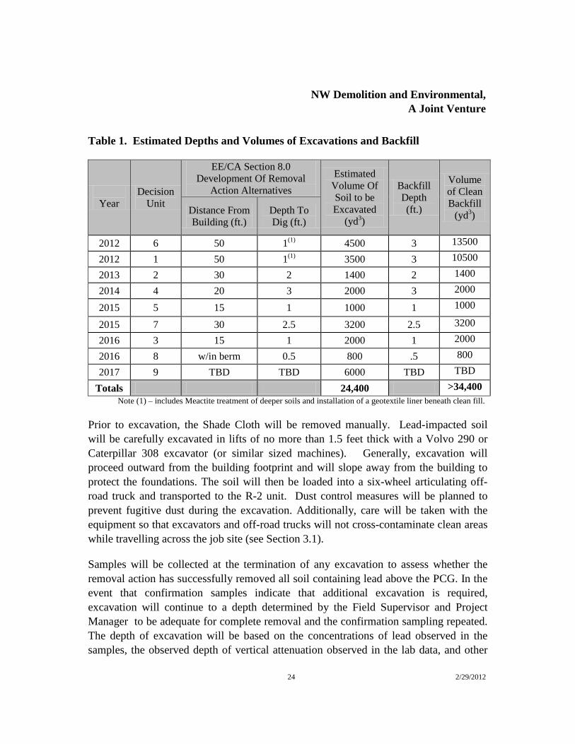
Soil containing elevated lead concentrations above the Preliminary Cleanup Goal (PCG) of 75 micrograms per kilogram (mg/kg) in each of the DUs will be excavated as identified in the EE/CA and summarized in Section 1.1. A summary of the extent and estimated volumes of soil to be removed and volumes and depths of backfill are provided in the Table 1 below. Actual volumes of soil removed will be dependent on the results of confirmation sampling as described later in this section. Likewise, backfill depths and volumes may vary with excavation depth (with the exception of DU #1 and #6). Note that the details of the removal action planned for DU #9 will be based on additional sampling and analysis yet to be completed.
NW Demolition and Environmental,
A Joint Venture
24 2/29/2012
Table 1. Estimated Depths and Volumes of Excavations and Backfill
Year
Decision Unit
EE/CA Section 8.0 Development Of Removal
Action Alternatives Estimated
Volume Of Soil to be Excavated
(yd3)
Backfill Depth (ft.)
Volume of Clean Backfill
(yd3) Distance From Building (ft.)
Depth To Dig (ft.)
2012 6 50 1(1) 4500 3 13500
2012 1 50 1(1) 3500 3 10500
2013 2 30 2 1400 2 1400
2014 4 20 3 2000 3 2000
2015 5 15 1 1000 1 1000
2015 7 30 2.5 3200 2.5 3200
2016 3 15 1 2000 1 2000
2016 8 w/in berm 0.5 800 .5 800
2017 9 TBD TBD 6000 TBD TBD
Totals 24,400 >34,400 Note (1) – includes Meactite treatment of deeper soils and installation of a geotextile liner beneath clean fill.
Prior to excavation, the Shade Cloth will be removed manually. Lead-impacted soil will be carefully excavated in lifts of no more than 1.5 feet thick with a Volvo 290 or Caterpillar 308 excavator (or similar sized machines). Generally, excavation will proceed outward from the building footprint and will slope away from the building to protect the foundations. The soil will then be loaded into a six-wheel articulating off-road truck and transported to the R-2 unit. Dust control measures will be planned to prevent fugitive dust during the excavation. Additionally, care will be taken with the equipment so that excavators and off-road trucks will not cross-contaminate clean areas while travelling across the job site (see Section 3.1).
Samples will be collected at the termination of any excavation to assess whether the removal action has successfully removed all soil containing lead above the PCG. In the event that confirmation samples indicate that additional excavation is required, excavation will continue to a depth determined by the Field Supervisor and Project Manager to be adequate for complete removal and the confirmation sampling repeated. The depth of excavation will be based on the concentrations of lead observed in the samples, the observed depth of vertical attenuation observed in the lab data, and other

NW Demolition and Environmental,
A Joint Venture
25 2/29/2012
factors. Excavation and sampling will continue until confirmation samples indicate successful removal has been achieved.
8.3 MAECTITE® Reagent Application
The actual process of applying MAECTITE® is still being determined at the time of this document production and will be detailed in a future submittal in 2012. Generally, liquid MAECTITE® reagent will be applied to the surface of the soil to be processed. Matted or overlying vegetation will be removed to the extent necessary just prior to reagent application to promote adequate wetting. In-situ application of the MAECTITE® chemical treatment process will be performed prior to excavation to process soil either before its disposal in the R-2 consolidation unit or being left in place (e.g. DU-6). After the reagents have been applied to the surface and have permeated the target area, the soils will be disrupted and mixed to homogeneity to lift depths up to approximately 1.5 feet (this disruption will be performed with heavy equipment fitted with a rake bucket, regular bucket or other effective means), first without excavating any material. Following an approximate three-hour reaction time period, the soil is ready to be excavated and transported to the R-2 unit.
Following the reaction period, an excavator fitted with a smooth grading bucket will be used to remove the lift of treated soil just above the depth of in-situ processing, leaving a small interface of processed material on top of the next underlying lift. Once a processed area is removed in a lift, the next area is exposed and prepared for reagent application or confirmation sampling. The sequence of reagent application, mixing, testing, and removal will be repeated across the surface areas confirmation sampling (Section 8.4) indicates adequate removal of soil containing lead at concentrations above the PCG.
In DU1 and DU6, the units where contaminated but stabilized soil is to remain in place, soil below the 1 ft. prescribed excavation will be treated with MAECTITE®, mixed in-place with an excavator, covered with a geotextile, and backfilled with clean beach sand from the borrow area.
8.4 Excavation Confirmation Sampling
Following completion of any single excavation (i.e. that associated with a single building), confirmation samples will be collected to document the remaining lead concentrations. Confirmation samples will be obtained using multiple increment

NW Demolition and Environmental,
A Joint Venture
26 2/29/2012
sampling methodology (MIS). Procedures for the excavation confirmation sampling are provided in the Field Sampling Plan (FSP) (Appendix B).
Sample Unit boundaries as well as the number and size of the sampling units, the number of increments and the sample mass will be determined based on actual conditions and contaminant distribution in any DU and in consultation between FWS and Geosyntec. Note that the term “decision unit” is used herein and in the EE/CA to describe those areas slated for soil removal. However, “decision unit” is also the term used in this section and interchangeably at times with “sampling unit” the referenced guidance to refer to “the defined area and depth (volume) of soil over which a decision will be made” or “an area and depth of soil over which an incremental sample is taken”
8.5 Witness Barrier Installation
Following excavation of the treated soils, the FWS-specified SunBlocker™ Premium 70% or 80% Shade Cloth that will cover each of the DUs prior to excavation will be reused on the floor of the final excavation to act as a physical barrier to Bonin petrels burrowing into soils that may still contain residual lead. When necessary, new Shade Cloth will be utilized. At the same time, the barrier will allow for infiltration of water and serve as a witness layer to notify those conducting future construction excavations of the potential presence of lead. The SunBlocker™ Shade Cloth will be manually installed on the floor of the excavation. Adjacent panels will be overlapped a minimum of 12 inches.
8.6 Backfilling
Each excavation will be backfilled with clean sand from the borrow area between the fuel pier and cargo pier. The clean sand will also be excavated with a Volvo 290 or Caterpillar 308 excavator (or similar sized machines) and hauled in an off-road truck to the designated DU. The sand will be dumped and carefully spread with a skid-steer loader (or similar) so as not to disturb the previously installed witness layer.
Prior to removal, the borrow sand will be characterized to provide baseline conditions before placement as backfill into the excavations. Additional discussion of the means and methods of the borrow area characterization is included in the FSP (Appendix B).

NW Demolition and Environmental,
A Joint Venture
27 2/29/2012
8.7 Erosion Protection
All vertical cuts will be sloped back to avoid instability due to wetness or loose material. Stabilization of the excavation surfaces will be accomplished using the SunBlocker Premium 70% or 80% Shade Cloth as described in Section 8.5.
Silt fences will be installed where there are downslopes adjacent to excavations to prevent potential run-off of lead contaminated soil. A 6-inch deep trench will be excavated, minimizing the disturbance on the downslope side. Wooden support stakes will be driven approximately 12 inches below the existing ground surface at approximately 8 foot intervals. Filter fabric will be stretched and fastened to the upslope side of the support stakes. The bottom of the fence will be anchored by placing the fabric in the bottom of the trench. The trench will be backfilled and compacted with the excavated material.

NW Demolition and Environmental,
A Joint Venture
28 2/29/2012
9. MANAGEMENT OF TREATED SOIL
9.1 General
Following excavation and treatment, material will then be transported to the R-2 unit and stockpiled in windrows for ease of management until the contaminated soils from each of the DUs have been excavated and treated.
Haul routes will be limited to the existing road network on the Refuge. It is the intention of NWDE to have one designated access per remediation area. Loaded trucks leaving the excavation area will be inspected prior to leaving the site and entering the Refuge’s existing road network. Manual brooms and scrapers will be used to grossly decontaminate the tires and underside and exterior of the dump trucks in an effort to minimize the spread of treated soil along the road network. The designated exit area where the dump trucks access the road network (leaving the excavation area) will be periodically swept clean after the dump truck leaves the area. At mid-morning, mid-afternoon, and the end of the day, the entire haul route will be policed for loose soil dropped from the dump trucks.
As stabilized waste materials are placed in R-2, a single layer of polyethylene film (DURA-SKRIM®) will be placed daily on the treated waste materials and anchored with sandbags placed around the perimeter and center of the cover. At the start of the working day, the cover will be removed from a working stockpile for additional waste placement and then replaced. At the end of each construction season, the DURA-SKRIM® will be placed on the treated waste and anchored with sandbags placed around the perimeter and center of the cover.
At present, the volume of soil estimated in the EE/CA to exceed the PCG (and thereby slated for treatment and storage) is expected to be at or near the capacity of the R-2 unit. As final excavation limits will be based on confirmation sampling results, final soil volumes will not be known until the project nears completion. Annual soil volumes and remaining storage capacity will be closely monitored over the course of the project and a determination of the need for alternate treatment/disposal methods evaluated on an annual basis. In the event that R-2 capacity will be exceeded, FWS will reevaluate many of the alternatives discussed in the EE/CA including the creation of alternate on-site repositories and off-site disposal.

NW Demolition and Environmental,
A Joint Venture
29 2/29/2012
9.2 Containment Cell Design and Retrofit
NWDE will use the existing R-2 basin for permanent internment of some or all of the stabilized waste materials. The unit will have existing water, sediment, and solid materials removed prior to placement of treated waste. One sidewall will be demolished and a ramp constructed on the eastern edge to allow vehicular access. R-2 will then be retrofitted with a drainage system to remove accumulated rainwater prior to placement of stabilized waste and the final grade covered with a permeable final cover system that will be sloped to drain surface water off the R-2 unit.
NWDE and Geosyntec will develop design specifications to convert the existing R-2 unit to a permanent containment cell. Existing information will be collected from FWS and any available as-built drawings. A series of design drawings and details will be prepared to accompany the specifications.
Layout drawings will be prepared for the general site, soil and sediment erosion control, R-2 cell construction and placement, and drain construction are anticipated along with detail pages as needed to illustrate fabric placement and construction details. A conceptual drawing for the R-2 unit is shown below.

NW Demolition and Environmental,
A Joint Venture
30 2/29/2012
Conceptual Cross-Section of Completed R-2 Unit
Management of leachate in the R-2 unit will utilize either new or existing drains installed in the floor to allow for infiltration of clean leachate into the subgrade. Currently, the discharge from R-2 unit is directed by underground piping to an open oceanfront discharge point to the south of the active runway. Engineering design of the modifications required to safely store the treated soil are underway and will be provided to FWS as a separate deliverable in prior to the 2012 field season.
A series of percolation tests will be conducted during the 2011 field season to aid in the design of a leachate management system for the redesigned R-2 unit. Percolation tests will be conducted at least two locations in the vicinity of the R-2 unit. At each test location, a six-inch diameter hole will be excavated to a minimum depth of 2 feet. A slotted 4-inch diameter PVC casing will be placed in the excavated hole and the annulus around the casing will be backfilled with the excavated soil. The casing will be presaturated with water. Several trials will then be performed by filling the casing with water and the rate at which the water drops will be measured at intervals over a period of time ranging from 1-10 minutes. Testing will be concluded after three consecutive

NW Demolition and Environmental,
A Joint Venture
31 2/29/2012
measurements are within 1/16th of an inch, and a minimum number of 6 measurements are recorded from each hole. This falling head type of test will be performed multiple times to demonstrate the repeatability of the results. Infiltration rates will be used in final design of the infiltration gallery and details will be provided in the design specifications to be submitted under separate cover.
9.3 Treatment Confirmation Sampling
Following annual stockpiling of treated soil in the R-2 consolidation unit, a single treatment confirmation sample will be collected and analyzed using Multiple Extraction Procedure (MEP). The MEP testing will be conducted on treated soils and is designed to simulate the leaching that will occur over the long-term. Additional discussion of the means and methods of the treatment confirmation sampling is included in the FSP (Appendix B).
9.4 Final Cover
Upon completion of waste placement in the R-2 unit, a Mirafi 180N/O Orange Delineation Nonwoven Geotextile will be installed immediately above the graded treated soil to serve as a witness barrier and to prevent burrowing. The geotextile will be unrolled on the treated waste in 15-foot wide panels. Adjacent panels will be overlapped a minimum of 12 inches.
The geotextile will be covered by a minimum of 2 feet of clean sand and/or concrete/asphalt debris graded with a minimum 2 percent slope to promote surface water drainage off of the R-2 unit.
The height of the Final Cover for the R-2 unit will not exceed the existing sand filter tanks located at the northwest corner of the R-2 unit. These sand filters currently have a warning beacon fixed to the top of the tanks in accordance with FAA regulations.
NW Demolition and Environmental,
A Joint Venture
32 2/29/2012
10. QUALITY ASSURANCE
A Quality Assurance Project Plan (QAPP) has been prepared to outline the Quality Control (QC) procedures that will be implemented during all sampling activities to ensure that the Date Quality Objectives (DQO) for the field sampling have been met. The QAPP has been prepared in accordance with USEPA Requirements for Quality Assurance Project Plans (USEPA 2001), and Guidance for Quality Assurance Project Plans (USEPA 2002) and is included in Appendix C.
A Construction Quality Assurance (CQA) Plan has also been prepared to summarize the CQA procedures that will be employed during the modification/construction of the R-2 unit and associated appurtenances. The CQA Plan is included in Appendix D.

NW Demolition and Environmental,
A Joint Venture
33 2/29/2012
11. PROJECT SCHEDULE AND REPORTING
A project schedule for the 2012 field season of work (DU6 and DU1) and an overall project schedule for all decision units are provided in Appendix E. NWDE will produce a detailed project schedule for each subsequent years work with the anticipated project durations.
Daily field reports will be submitted to FWS to document site activities. The daily reports will include a narrative of the day’s events and activities, including weather conditions; equipment and key personnel on site; hours of operation; summary of progress; equipment used; description of construction procedures and their performance; and a summary of any testing and monitoring.
Interim reports will be submitted to FWS upon completion of each Decision Unit (DU). The Decision Unit Report will include the results for confirmation samples collected from the excavations, amount of soil and debris treated, excavated, and disposed of in the R-2 consolidation unit. The DU Reports will also include summary data related to abatement and demolition activities. Reports for waste disposed offsite will also be included in the DU Reports.
NWDE will provide separate draft and final CQA reports detailing modifications to the R-2 consolidation unit. Each report will contain a detailed narrative description of significant aspects of the field and laboratory CQA activities. The documentation of construction activities (presented on the daily field reports) will be included as appendices to the CQA report. The final report will contain as-built drawings for the drainage system, subgrade, protective soil cover grades, as well as panel layout drawings for the geotextile cover.
After the remedy is determined to be “operational and functional,” the Team will prepare an Operation and Maintenance and Long-Term Monitoring Plan that details methods by which the remedy may be monitored to ensure it performing as expected and the environment is protected. The Plan will be prepared in general accordance with NCP, Subpart E, section 300.435 and “Operation and Maintenance in the Superfund Program,” OSWER 9200.1-37FS, EPA 540-F01-004, May 2001. Typical Plan elements might include 1) Maintenance of Landfill Cap including ensuring appropriate controls for runoff and repairing cracks, animal burrow damage, and areas of settlement and erosion; and 2) Leachate monitoring.

NW Demolition and Environmental,
A Joint Venture
34 2/29/2012
12. KEY PERSONNEL
The project team is structured with a Program Manager, Project Manager, and Lead Environmental Manager whom the Site Project Manager will report to as well as various team members responsible for task specific operations. The following is an overview of personnel directly responsible for supporting the efforts of this contract in 2011. NWDE reserves the right to replace team members as necessary with prior FWS approval.
Program Manager: Richard Wayper, NWDE
Richard Wayper, who will serve as Program Manager has been responsible for management and execution of numerous large scale, environmentally challenging and complex projects. He has a master’s degree in environmental and economic geology and is a registered geologist. Richard has more than 20 years of industry experience and has managed all aspects of facility closures and waste management. Richard’s responsibilities will include:
• Providing sufficient resources to the project team so that they can respond fully to the requirements of this project.
• Providing timely and accurate project reporting to the COTR and other FWS staff and serve as a single-point-of-contact for project related matters.
• Maintaining accurate project accounting and timely invoicing.
• Providing direction and guidance to the Construction and Environmental Managers.
• Supporting the project team with additional resources, as necessary.
Environmental Manager: Sean Ragain, RG, Geosyntec
Sean Ragain has more than 23 years of experience providing environmental and natural resource consulting services to governmental agencies and more than 15 years of continuous service to FWS Regions 1 and 8. Sean has managed or directed the execution of delivery orders at more than 50 hatcheries and Refuges throughout the western states, Alaska and Pacific Islands. More than a dozen of those orders have been related to projects on Midway Atoll. Sean has extensive experience in the management of FWS projects in remote locations having directed work for FWS on the islands of

NW Demolition and Environmental,
A Joint Venture
35 2/29/2012
Tern, Laysan, Oahu, Hawaii, Kauai, Maui, and Farallon in addition to Midway. Sean’s responsibilities for this project include:
• Establishing QA/QC procedures and independently monitoring project performance.
• Serving as an alternate point of contact for FWS on matters related to soil removal actions and treatment.
• Ensuring that major project deliverables are reviewed for technical accuracy and completeness before their release.
• Reviewing the quality of the data gathered during the course of the project.
• Assisting the Program Manager in corrective measure implementation.
• Reviewing and approving the project plans, related preplanning documents, and reports.
• Assigning duties to the Geosyntec project staff and orienting the staff to the needs and requirements of the project.
• Obtaining the approval of the Program Manager for proposed variances to the scope of work, including variances to project plans.
• Supervising the performance of the Geosyntec project team.
Project Manager: Darin Leibelt, NWDE
Darin Leibelt manages NWDE’s Hawaii Division and has over twelve years of experience as a project manager and environmental professional. His project experience includes environmental consulting, safety management, organizing schedules, and coordinating crews and subcontractors in completing demolition and ACM and LBP abatement. Darin’s responsibilities will include:
• Reviewing and approving the project plans, related pre-planning documents.
• Obtaining the approval of the Program Manager and/or Chief Technical Advisor for proposed variances to the scope of work, including variances to project plans.
• Assigning duties to the project staff and orienting the staff to the needs and requirements of the project.

NW Demolition and Environmental,
A Joint Venture
36 2/29/2012
• Supervising the performance of his project team.
• Providing budget and schedule control.
• Ensuring compliance with the CQAP, QAPP and FSP.
• Reviewing and approving NWDE subcontractor work.
• Ensuring that demolition and abatement deliverables are reviewed for technical accuracy and completeness before their release.
• Regularly communicating project status, progress, and any problems to the COTR and appropriate Refuge staff in conjunction with the Environmental Manager and with the approval of the Program Manager or Technical Officer.
Abatement Supervisor: Gary Lewis, Iniki
As Abatement Supervisor, Gary Lewis will manage the abatement workers on general asbestos abatement, LBP abatement, and painting.
Field Forman: Jeremy Kauwe, Iniki
Mr. Kauwe will be responsible for identifying lead hazards and selecting appropriate controls for exposure. He has the authority to take corrective measures if necessary as specified in 29 CFR 1926.32. He will oversee the project, guide and help the workers with the lead removal activity.
Site Supervisor: Everett White, NWDE
Everett White is a field superintendent directly responsible for the successful implementation of the specific work plan along with the personnel and equipment of the project. He has of 35 years of technical experience in all facets of the project, from heavy equipment operations to crew management to being the first point of contact to the client. Specifically Everett was the Superintendent for the work conducted on Johnston Island including the lead soils removal project and the plutonium landfill capping project.
His duties will include assigning duties to the demolition team and supervising their performance.

NW Demolition and Environmental,
A Joint Venture
37 2/29/2012
Site Project Manager: Mike Schott, EIT, Geosyntec
Mike Schott has been actively involved in the full range of project phases from project planning and management to site assessment and data collection and finally to field implementation and reporting. Mr. Schott is an experienced construction manager but also a biologist and engineer who understands designs and the work necessary for a successful project completion. He recently served as a field engineer and environmental sampler for a large site investigation involving multiple phases of soil and groundwater sampling. His duties will include:
• Day-to-day oversight of remedial excavations, the installation of geotextiles and the placement of treated wastes in the R unit.
• Ensuring compliance with the FSP, QAPP, and On-Site Waste Management Plan. .
• Regularly communicating project status, progress, and any problems to the COTR and appropriate Refuge staff in conjunction with the Environmental Manager and with the approval of the Program Manager or Technical Officer.
Ex-Situ Stabilization: Chris Rice, Sevenson
Chris Rice is a Project Manager/Treatment Manager with Sevenson and oversees treatability studies and is very experienced in the application of the MAECTITE® technology. He has more than 30 years of experience in the chemical, environmental, and remediation industry and has supervised multidisciplinary personnel on a wide range of projects, and coordinating projects, bids, and contracts in the area of fixation technology.
Mr. Rice will ensure the delivery of MEACTITE to Midway and provide off-island technical support to the environmental team to ensure its proper application.
Disposal Facility Design: Greg Corcoran, PE, Geosyntec
Greg Corcoran, PE, is a Principal civil engineer based in California who focuses on the design, construction, and operation of engineered systems for waste containment and site development at locations impacted by the presence of contaminants in soil, soil gas, and groundwater. Specializing in the design and construction of liner and cover systems for waste containment facilities for more than 20 years, Greg has been involved with the design and/or construction of containment systems, both final cover and base liner, for

NW Demolition and Environmental,
A Joint Venture
38 2/29/2012
more than 60 landfills at sites throughout the United States utilizing the latest advances in geosynthetic, recycled, and natural material technology applications. He serves on several American Society of Testing and Materials (ASTM) D35 subcommittees for preparation and approval of ASTM standards and test methods relating to geosynthetic materials. Greg is a registered professional engineer in California and other states.
Greg’s duties on Midway include the selection of appropriate geotextiles, final design of the modified R-unit and final approval of the construction completion reporting requirements.

NW Demolition and Environmental,
A Joint Venture
39 2/29/2012
13. BIBLIOGRPAHY
Code of Federal Regulations Title 40: “Protection of Environment, Chapter I,
Subchapter J, Part 300 – National Oil and Hazardous Substances Pollution Contingency Plan.” Available from epa.gov/docs/epacfr40/Chapt-I.info/subch-j.htm; Internet.
GeoEngineers, Inc. 18 January 2011. Engineering Evaluation/Cost Analysis, Midway
Atoll National Wildlife Refuge, Midway Island. GeoEngineers, Inc., 16 November 2004, revised 20 March 2009. Spill Prevention,
Control and Countermeasures Plan for U. S. Fish and Wildlife Service (Midway Atoll National Wildlife Refuge).
Painting and Decorating Contractors of America. 1995. Painting and Decorating
Craftsman’s Manual, Eighth Edition, www.pdca.org. U.S. Fish & Wildlife Service, 7 July 2011. Memorandum to Regional Director, Region
I, from Assistant Regional Director, Budget and Administration, Region I: Action Memorandum for a Non-Time Critical Removal Action at Midway Atoll National Wildlife Refuge, Sand Island.
U.S. Environmental Protection Agency, “Guidance on Conducting Non-Time-Critical
Removal Actions Under CERCLA,” Office of Solid Waste and Emergency Response, PB93-963402, 9360.0-32, EPA540-R-93-057, August 1993.
U.S. Environmental Protection Agency. March, 2001. EPA Requirements for Quality
Assurance Project Plans. EPA/240/B-01/003. U.S. Environmental Protection Agency. December, 2002. Guidance for Quality
Assurance Project Plans. EPA/240/R-02/009.

FIGURES

NORTH WEST DEMOLITIONAND ENVIRONMENTAL,
A JOINT VENTURE
N
Figure:
MARCH 20121
SITE LAYOUT WITH DECISION UNITS
REMOVAL OF LEAD BASED PAINTFROM STRUCTURES AND LEAD
CONTAMINATED SOIL AT MIDWAY ATOLL

NORTH WEST DEMOLITIONAND ENVIRONMENTAL,
A JOINT VENTURE
N
Figure:
MARCH 20122
SITE LAYOUT - DECISION UNIT 1
REMOVAL OF LEAD BASED PAINTFROM STRUCTURES AND LEAD
CONTAMINATED SOIL AT MIDWAY ATOLL

NORTH WEST DEMOLITIONAND ENVIRONMENTAL,
A JOINT VENTURE
N
Figure:
MARCH 20123
SITE LAYOUT - DECISION UNIT 2
REMOVAL OF LEAD BASED PAINTFROM STRUCTURES AND LEAD
CONTAMINATED SOIL AT MIDWAY ATOLL
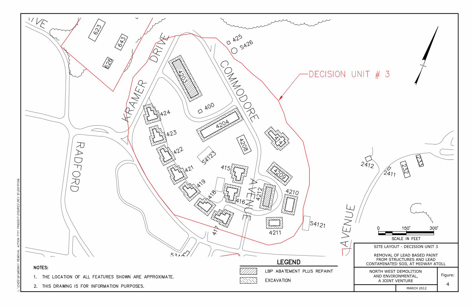
NORTH WEST DEMOLITIONAND ENVIRONMENTAL,
A JOINT VENTURE
N
Figure:
MARCH 20124
SITE LAYOUT - DECISION UNIT 3
REMOVAL OF LEAD BASED PAINTFROM STRUCTURES AND LEAD
CONTAMINATED SOIL AT MIDWAY ATOLL
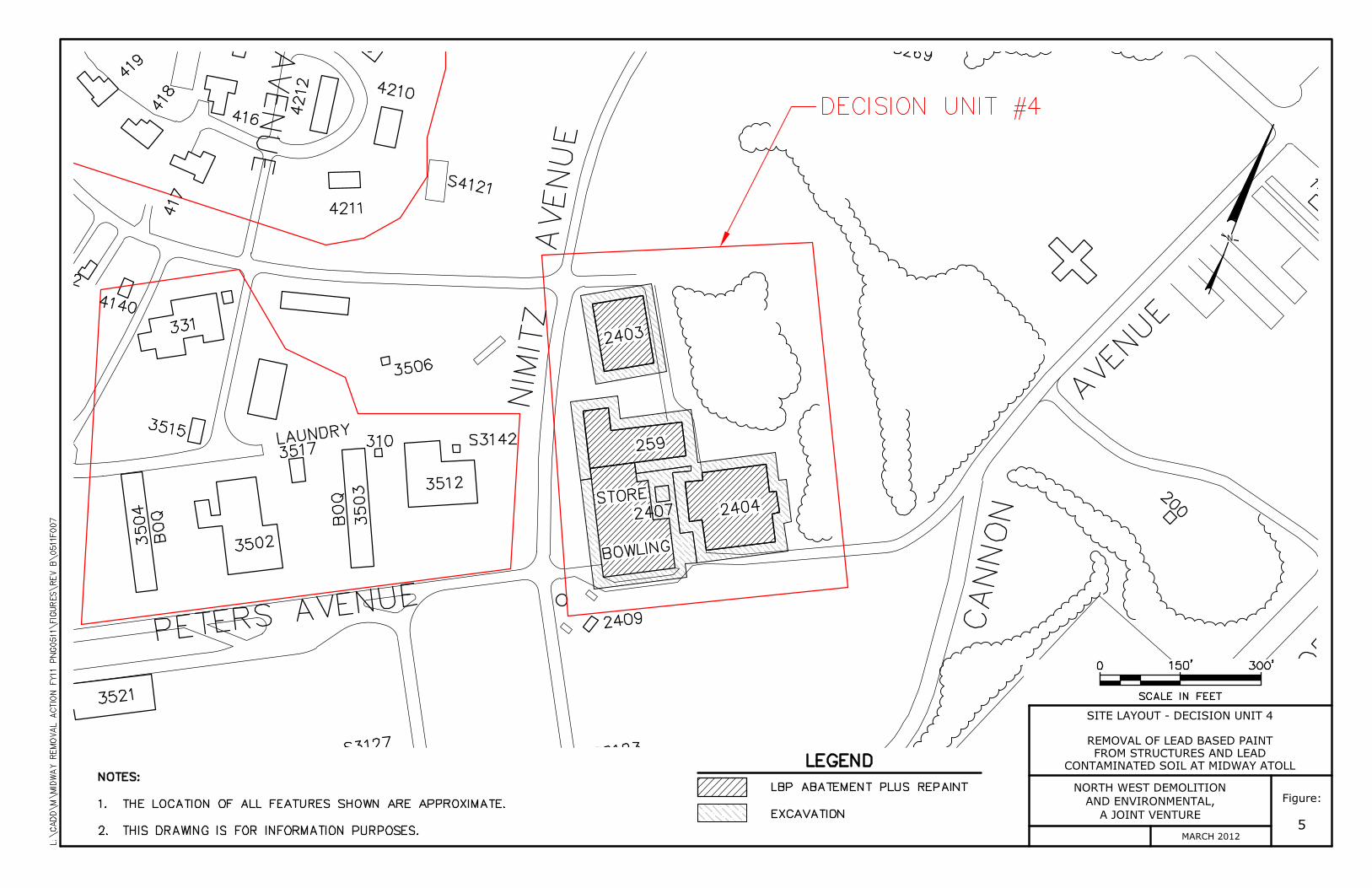
NORTH WEST DEMOLITIONAND ENVIRONMENTAL,
A JOINT VENTURE
N
Figure:
MARCH 20125
SITE LAYOUT - DECISION UNIT 4
REMOVAL OF LEAD BASED PAINTFROM STRUCTURES AND LEAD
CONTAMINATED SOIL AT MIDWAY ATOLL

NORTH WEST DEMOLITIONAND ENVIRONMENTAL,
A JOINT VENTURE
N
Figure:
MARCH 20126
SITE LAYOUT - DECISION UNIT 5A
REMOVAL OF LEAD BASED PAINTFROM STRUCTURES AND LEAD
CONTAMINATED SOIL AT MIDWAY ATOLL

NORTH WEST DEMOLITIONAND ENVIRONMENTAL,
A JOINT VENTURE
N
Figure:
MARCH 20127
SITE LAYOUT - DECISION UNIT 5B
REMOVAL OF LEAD BASED PAINTFROM STRUCTURES AND LEAD
CONTAMINATED SOIL AT MIDWAY ATOLL

NORTH WEST DEMOLITIONAND ENVIRONMENTAL,
A JOINT VENTURE
N
Figure:
MARCH 20128
SITE LAYOUT - DECISION UNIT 6
REMOVAL OF LEAD BASED PAINTFROM STRUCTURES AND LEAD
CONTAMINATED SOIL AT MIDWAY ATOLL

NORTH WEST DEMOLITIONAND ENVIRONMENTAL,
A JOINT VENTURE
N
Figure:
MARCH 20129
SITE LAYOUT - DECISION UNIT 7
REMOVAL OF LEAD BASED PAINTFROM STRUCTURES AND LEAD
CONTAMINATED SOIL AT MIDWAY ATOLL

NORTH WEST DEMOLITIONAND ENVIRONMENTAL,
A JOINT VENTURE
N
Figure:
MARCH 201210
SITE LAYOUT - DECISION UNIT 8
REMOVAL OF LEAD BASED PAINTFROM STRUCTURES AND LEAD
CONTAMINATED SOIL AT MIDWAY ATOLL

APPENDIX A
Manufacturer’s Specifications


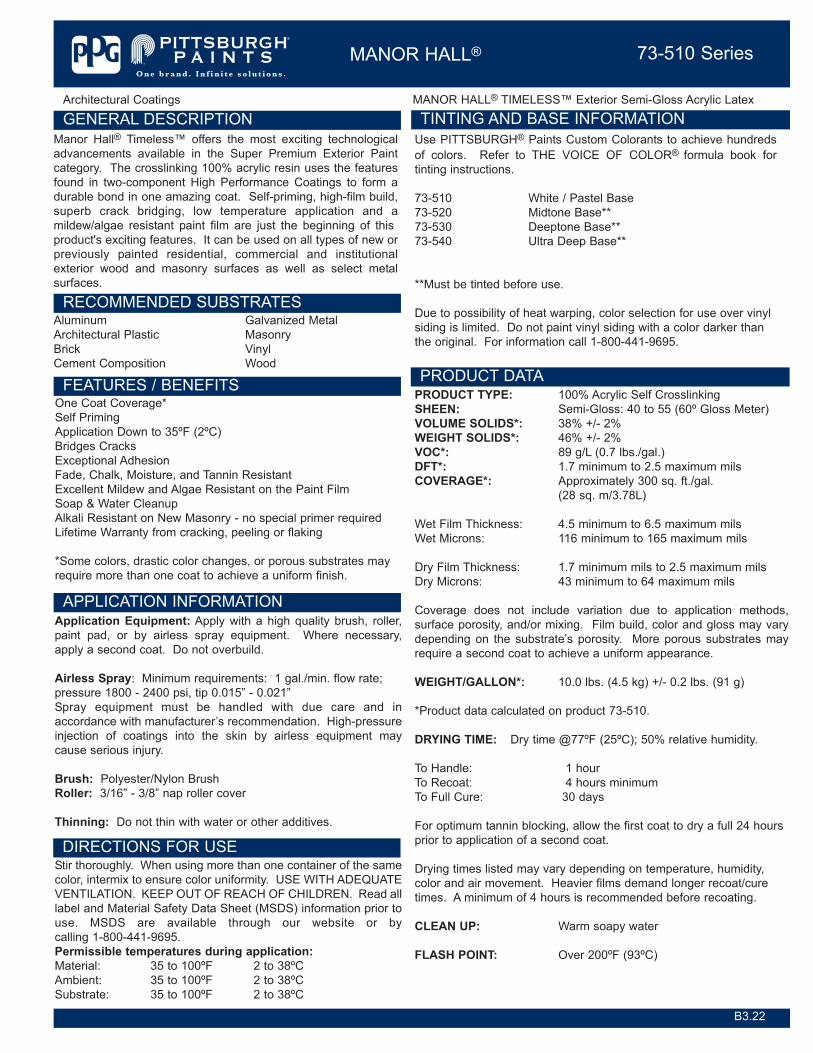
Architectural Coatings MANOR HALL® TIMELESS™ Exterior Semi-Gloss Acrylic Latex
GENERAL DESCRIPTION
PRODUCT DATA
MANOR HALL® 73-510 Series
RECOMMENDED SUBSTRATES
FEATURES / BENEFITS
Manor Hall® Timeless™ offers the most exciting technologicaladvancements available in the Super Premium Exterior Paintcategory. The crosslinking 100% acrylic resin uses the featuresfound in two-component High Performance Coatings to form adurable bond in one amazing coat. Self-priming, high-film build,superb crack bridging, low temperature application and amildew/algae resistant paint film are just the beginning of thisproduct's exciting features. It can be used on all types of new orpreviously painted residential, commercial and institutionalexterior wood and masonry surfaces as well as select metalsurfaces.
Aluminum Galvanized MetalArchitectural Plastic MasonryBrick Vinyl Cement Composition Wood
PRODUCT TYPE: 100% Acrylic Self CrosslinkingSHEEN: Semi-Gloss: 40 to 55 (60º Gloss Meter)VOLUME SOLIDS*: 38% +/- 2%WEIGHT SOLIDS*: 46% +/- 2%VOC*: 89 g/L (0.7 lbs./gal.)DFT*: 1.7 minimum to 2.5 maximum milsCOVERAGE*: Approximately 300 sq. ft./gal.
(28 sq. m/3.78L)
Wet Film Thickness: 4.5 minimum to 6.5 maximum milsWet Microns: 116 minimum to 165 maximum mils
Dry Film Thickness: 1.7 minimum mils to 2.5 maximum milsDry Microns: 43 minimum to 64 maximum mils
Coverage does not include variation due to application methods,surface porosity, and/or mixing. Film build, color and gloss may varydepending on the substrate’s porosity. More porous substrates mayrequire a second coat to achieve a uniform appearance.
WEIGHT/GALLON*: 10.0 lbs. (4.5 kg) +/- 0.2 lbs. (91 g)
*Product data calculated on product 73-510.
DRYING TIME: Dry time @77ºF (25ºC); 50% relative humidity.
To Handle: 1 hourTo Recoat: 4 hours minimumTo Full Cure: 30 days
For optimum tannin blocking, allow the first coat to dry a full 24 hoursprior to application of a second coat.
Drying times listed may vary depending on temperature, humidity,color and air movement. Heavier films demand longer recoat/curetimes. A minimum of 4 hours is recommended before recoating.
CLEAN UP: Warm soapy water
FLASH POINT: Over 200ºF (93ºC)
TINTING AND BASE INFORMATIONUse PITTSBURGH® Paints Custom Colorants to achieve hundredsof colors. Refer to THE VOICE OF COLOR® formula book fortinting instructions.
73-510 White / Pastel Base73-520 Midtone Base**73-530 Deeptone Base**73-540 Ultra Deep Base**
**Must be tinted before use.
Due to possibility of heat warping, color selection for use over vinylsiding is limited. Do not paint vinyl siding with a color darker thanthe original. For information call 1-800-441-9695.
DIRECTIONS FOR USEStir thoroughly. When using more than one container of the samecolor, intermix to ensure color uniformity. USE WITH ADEQUATEVENTILATION. KEEP OUT OF REACH OF CHILDREN. Read alllabel and Material Safety Data Sheet (MSDS) information prior touse. MSDS are available through our website or bycalling 1-800-441-9695.Permissible temperatures during application:Material: 35 to 100ºF 2 to 38ºCAmbient: 35 to 100ºF 2 to 38ºCSubstrate: 35 to 100ºF 2 to 38ºC
B3.22
One Coat Coverage*Self PrimingApplication Down to 35ºF (2ºC)Bridges CracksExceptional AdhesionFade, Chalk, Moisture, and Tannin ResistantExcellent Mildew and Algae Resistant on the Paint FilmSoap & Water CleanupAlkali Resistant on New Masonry - no special primer requiredLifetime Warranty from cracking, peeling or flaking
*Some colors, drastic color changes, or porous substrates mayrequire more than one coat to achieve a uniform finish.
APPLICATION INFORMATIONApplication Equipment: Apply with a high quality brush, roller,paint pad, or by airless spray equipment. Where necessary,apply a second coat. Do not overbuild.
Airless Spray: Minimum requirements: 1 gal./min. flow rate;pressure 1800 - 2400 psi, tip 0.015” - 0.021”Spray equipment must be handled with due care and inaccordance with manufacturer’s recommendation. High-pressureinjection of coatings into the skin by airless equipment maycause serious injury.
Brush: Polyester/Nylon BrushRoller: 3/16” - 3/8” nap roller cover
Thinning: Do not thin with water or other additives.

MANOR HALL® 73-510 Series
MANOR HALL® TIMELESS ™ Exterior Semi-Gloss Acrylic Latex Architectural Coatings
GENERAL SURFACE PREPARATIONImproper surface preparation will void the TIMELESS™ Lifetime Warranty. Surface must be clean, dry, and free of dirt, loose and peelingpaint, mildew, chalk, and other surface contaminants. Putty nail holes; caulk large cracks and open seams. Sand all glossy, rough, andpatched surfaces. Remove mildew by using PPG MILDEW CHECK® Multi-Purpose Wash, 18-1. Before use, be sure to read and follow theinstructions and warnings on the label. WARNING! If you scrape, sand, or remove old paint, you may release lead dust or fumes. LEADIS TOXIC. EXPOSURE TO LEAD DUST OR FUMES CAN CAUSE SERIOUS ILLNESS, SUCH AS BRAIN DAMAGE, ESPECIALLY INCHILDREN. PREGNANT WOMEN SHOULD ALSO AVOID EXPOSURE. Wear a properly fitted NIOSH-approved respirator and preventskin contact to control lead exposure. Clean up carefully with a HEPA vacuum and a wet mop. Before you start, find out how to protectyourself and your family by contacting the USEPA National Lead Information Hotline at 1-800-424-LEAD or log on to www.epa.gov/lead. InCanada contact a regional Health Canada office. Follow these instructions to control exposure to other hazardoussubstances that may be released during surface preparation.
NEW WOOD: Sand smooth and wipe clean. Seal knots or resinous areas before painting. Countersink all nails. Putty flush with surface.Apply one to two coats of TIMELESS. Tannin bleeding woods require two coats. The first coat must be completely dry before re-coating.For optimum tannin blocking performance, PPG recommends allowing the first coat to dry a full 24 hours prior to the application of asecond coat.
PREVIOUSLY PAINTED WOOD: Remove excessive chalking, loose, peeling or flaking paint. Feather back all rough edges to soundsurface by sanding. Prime all bare wood areas.
CONCRETE BLOCK, VERTICAL MASONRY: New concrete should cure for at least 30 days prior to priming. Fill block with anappropriate block filler. Surfaces previously coated with water thinned cement-base paint must be prepared with extra care. If the coatingsappear to be adhering tightly, a masonry sealer may be applied to seal the surface. Check adhesion by applying a piece of masking tape.If it peels off and has loose particles, remove all chalking or crumbling material.
METAL: Rust and other surface contamination must be removed from ferrous metals, aluminum, copper, brass, and galvanized steel.Then the surface must be cleaned thoroughly to remove any dust. Use appropriate primer.
GALVANIZED STEEL: Caution must be used when selecting coatings for use on all galvanized metal surfaces. These substrates mayhave a factory-applied stabilizer, which is used to prevent white rusting during storage and shipping. Such stabilizers must be removed byeither brush blasting, sanding or chemical treatment. Use appropriate primer.
ALUMINUM AND VINYL SIDING: Siding may present potential adhesion problems. Topcoat should be spot applied, allowed to cureovernight, then evaluated for adhesion. If adhesion is good, the application may proceed. One way to check adhesion is by applying a pieceof masking tape to test the topcoat. If the topcoat peels off easily, the surface must be scuff sanded prior to proceeding to ensuremechanical adhesion. Do not paint with a color darker than the original vinyl siding.
B3.22 8/2007
PACKAGING
RECOMMENDED PRIMERS
PPGAF believes the technical data presented is currently accurate: however, no guarantee of accuracy, comprehensiveness, or performance is given or implied. Improvements incoatings technology may cause future technical data to vary from what is in this bulletin. For complete, up-to-date technical information, visit our web site or call 1-800-441-9695.
PPG Industries, Inc.Architectural CoatingsOne PPG PlacePittsburgh, PA 15272www.pittsburghpaints.com
Technical Services1-800-441-96951-888-807-5123 fax
PPG Architectural Finishes400 S. 13th StreetLouisville, KY 40203
PPG Canada, Inc.Architectural Coatings4 Kenview BlvdBrampton, ON L6T 5E4
Architect/Specifier:1-888-PPG-IDEA
Aluminum 6-204, 90-712Concrete Masonry Units, Masonry 4-100(Block Fillers)Concrete, Masonry (Primers, Sealers) 4-603, 4-808, 4-809Ferrous Metal 6-208, 6-212, 90-712Galvanized Steel 6-209, 90-712Hardboard 17-921, 17-922Plywood 2 coatsStaining Woods 2 coats or 17-921,
17-922Wood Self-priming
1-Gallon (3.78 L)5-Gallon (18.9 L)
LIMITATIONS OF USEApply when air, surface and product temperatures are 35ºF (2ºC)and surface temperature is at least 5ºF (3ºC) above the dew point.For optimum application properties, bring material to at least 50ºF(10ºC) prior to application. Air and surface temperature mustremain above 35ºF (2ºC) for the next 24 hours. Avoid painting latein the day when dew and condensation are likely to form or whenrain or snow are expected. Do not apply in direct sunlight. Do notoverbuild. Do not thin with water or other additives. PROTECTFROM FREEZING. Not recommended for use on steps or floors.While this product provides a mildew resistant coating, growth maystill occur if the substrate is not properly prepared prior to paintingand/or if the substrate is consistently exposed to conditionsconducive to mold, mildew, and algae. Examples of theseconditions include, but are not limited to, under eaves, behindshrubbery and trees, and in areas that are consistently damp withlittle to no direct sunlight.

�������������������������� ��������������
������������� ��������������
���
���������������������������������� �������!��"#���$�%����&'%�(�'�''�%��&)�(&�%'(�*'�%����&+ � � (�%,�����%'���&��-��.(
�� ��������
������������� ��������
�
�
�
������������������� � %,��''%/*/��&,0��� 1��.��0���21����(
���������������������
������������ !�"���� #��$����� �
����������%��%��&
'(���������������
��������������������������
� 3�!��# �14����4��5 ��.5��
�����)�
*�����*������
������+�������������������,���������-
6$7����8�
��
��
������������������%��������%��.�+ �����
����-�����"����.��������9.�9��"� �3�� �"���.�" ���1����.��������#����� �� ��!���"� ����:�1 3�!�� ""� 9 ����!3�.9���-2.������.��#���2�.����
�
��
/%��.�+ ����������0��� ����
*������ ��)� ����� �
*����� �
$9.����.�� ���5��#��3�����:��� �����.�#��"��)���.��3�5��#� ��;� ���9����� ��.���<��2�.�� �������"#��3���.���� ����� ������������ �3�4.�������6 �#��#.�.�"#�3� 4����# �����"
+$)�����=���77��$�������$=�>��?$7�@)���@���?$�� ��7��6$���6� +���$�����$��7�$���?$��+$��+$)����$7�����7�$�� $�$��
� 3�!��# �14����4���# ���
����� ���"��.��3���.�:�.5����"��4�� ����44�����.�������� ��# A ���
���������������������������������� �� ��������������&������1��2��) ����'(�������������*���������������,2'�*�-�������/�'3�'(��������������������, 4��56��4�#�� ##-�
�.��2���4���� � �.��2���4���� � �.��2���4���� � $�9������312�.1��1 3����������#��4.��.5��"02 ���.������� ��.�5 �����"�������
��� ������0��������������������!��
����������������������������� ������&����7�&����������������)�&��������������� ����������������������� ������7�����������������(�����������������������%����������������8������� �������������������
��� ���1���.-��� %�'*�*�� ���%���2#�������3����� ���''/*� %����&�!��.-3��#.-3(��# �.� %%��'� ����%������.����.-��� �*�%,*/ ����%�
��� �3������� 9
������0:;������������.����.���+���

�*��<�����=������*.></�����*��/������������� ������������ ������������ $�����:!.? # !�"���� #��
5���������������
���������
�)�������
*�����
*������
��������� ������
�
�
�
�
�
@��
+#��:�4.�� �����1.9�� �3��.�� �����������11��� ���3�4���#��3���5��#�������"�5 ���4.�� ���� ���%��1��������:��2��"��3������.2������:��11��� ���1���� �� ������.�7�1.9���.�� 1�� ������.�#��"� ����#.���6 �#��:����#.�.�"#�3�5��#��. 2� ��5 ����.���������."��A����:������ ����� .����������.�9�����.���#������7�1.9���.�4���#� ���<��2�2���.��5 �1� ��� ��������4��.��!�� �#��"���4�!�� �#��"�������"�� ��.���4����2�� �.�3� ������.�������2�.9���� ���4��� �����2�� ��.��.��.-3"���!3�� �����2���.�����4��5 ��.5�������:�1���� �� �9�����11��� ���3� ����#.5��#����.�� �����.��� !��<��2�2���.��5 �1� ��� ������� .��.���������9.1����"
�4���"����.�������� ��.��� �3��32��.4�.9���-2.�����.���312�.1��.4�.9���-2.�����.����������"�.��2�������� 4��������.4��#��2�.�������.�� ��� ��������+���7���+����7�����7���+=�7�����7��?=��+�$���11��� ���3B�# 9��� ���� �� 4��3� � ��#������4.�1 ��.�� 9 �� !������9���"�9�� �3�#��"�!3�1.��#��.� �����.����.���.���.�9�����"�2���.�
�.��2���4������ �1�������� ���312�.1 ��� ��3��+.�� ���2.��.����� �1�����2��� �����11��� ���3��4�� �"��;� ��������# 9��!������"������.����# ���
)��� ���-���"���#��"� "�������� !���4.���#������.�����"�4���
5���.���������������
�+��������������
��.12��3���.� ����#��������!3���1.9��"� ���2���.���4�.1��#��9������3�.4��#������������4�#������� �4������.� ���.���# ���!��� :�����9.�9��"� �3�2���.� �����:�.��5��#.������� !���� ����"
��� �4����.���4�#� ����� �2������������� ���5����.����� ����#���.�� �����1 3�!����
� ����� �������%��8�� ������������.��������
@���4�"#������#.����5� �� 22�.2�� ���2�.�����9���;��21���� ������4�.�� �����!�� �#��" 22 � ����&�+>$(�5��#� �4����4 ��2�����.2�� �������2.����9��2��������1.��
�
?��
� ������+ �������(��� ��.���:�.5�
������� ������������ �
'(��������������� �������
� ��.12.����.��2�.������1 3����������#��4.��.5��"�1 ���� ��0� �!.��.-����1�� ��.-���C.-����
5����������������� ������ �
�.� ���.���# ���!��� :�����9.�9��"� �3�2���.� �����:�.��5��#.������� !����� ����"�9 �� �������.�����"� �� ���<��2��������� �3� �����2�.�������2���.�����4�.1�������"�� .��.���.��#�.��5 �:��#�.�"#��2������1 ���� ���$9.���!�� �#��"�9 2.��.��1�����.9���� ��;� ���9����� ��.���6� �� 22�.2�� ������2�� �.��5#���9����� ��.������ ��;� ��������.�� 22�.2�� ���2���.� ��2�.�����9���;��21����&���������.��,(
��.2��� :��4�5��#.������:���.9���.�� ������4�.1��2���� �� ��$22�. �#����� ���4�.1�25��������9��������3����.���5�����5 �����.�������! ��1�����.���.�4����� �� ���6 �#�2��� "������.� ���44��������� �1����2� ���.��2�.����� ��4.��.5���+.�� ��� ����.������2��� "��5��#��.��.1!����!���� !�.�!����1 ���� ���"�� ����� ��#��9��1��������.��� �.1 ��.���� ��#� ���2� �������.�� �����4.�����2.� �� ��.����"��.��.� ����"�� ��.��&���������.��%�(�� ��2.���.4�9� � ����������5 �������2.� ���.��� ��.���+.�� 1�� ��� !�.�!����1 ���� ��1 3�2.����#��� 1��# A ��� ���#���2������2�.�������.��0����������.�%�4.���1��"���3��.�� �����4.�1 ��.�� ��������.��%��4.��5 �������2.� �
�%�������� ��������
3����������������������
� $9.������2��� ��.4��2������1 ���� �� ������.44� ����.�� ���5��#��.����5 ���5 3����� ��� �����5�������4.�1��#������9 ��� ��#.��������4��#��2�.�����# ��� �������9��.�1��� �2.�����.��&��5�����5 ���5 3����.���.�� ��(
������� �������� �
<����� ��� �
A��
��.2��� :��4�5��#.������:���.9���.�� ������4�.1��2���� �� �� ������5��#�5 ���� ���1.2��2�4�5 ����.��!���.�� !�.�!�5��#� ����������3�1 ���� �� ���2� ������ �� 22�.2�� ���5 ������2.� ���.�� ������ ��2.���.4�9� � ����������5 �������2.� ���.��� ��.�
������ ��� �
����� 0:;������������.����.���+���

�*��<�����=������*.></�����*��/������������� ������������ ������������ $�����:!.? # !�"���� #��
��.������ ��.�� ����5��#��.� ����"�� ��.������.������.��"�� ���.�� �����2�.�������4�.1������������"#����� ���3���..�� ���5���9����� ���� �� �� 5 3�4�.1����.12 ��!���1 ���� ��&���������.��%�(� ���4..�� �������:��<��2��.�� �������"#��3���.���� ����� ������������ �34.�������+.�� �������# ��# 9��!����.2�����1����!��� ��4���3����� ���� ���:�2���2��"#��.�2��9������ : "��� .��.����.��������� !������.�� �������)��� 22�.2�� ����.�� ��1����.� 9.�����9��.�1��� ���.�� 1�� ��.��� .��.����.���!��.5��#��4.��.5��"���12�� ����0��@�C��+
����.�� 22�.2�� ���2���.� ��2�.�����9���;��21����&���������.��,(��� ���"������:��"� ���1.:��"��#.����!��2�.#�!�������� �� ��5#�����#���1 ���� �����# ���������.���� ��2�.�������� .��.���5 ��.5�� .��.��"�������3���.��.���:���.����.�#��"��$9.���!�� �#��"9 2.��.��1������4������"��.�1 �������#��1 ���� ��2�������� ����2�� �.�3�# A ��������.��35��#� ��;� ���9����� ��.��.��5� �� 22�.2�� ������2�� �.���<��2�����#��.��"�� ���.�� �����.� �� 22�.9��� ����� ��9��1 ���4�.1� ��.12 ��!���1 ���� ���:�2����"#��3���.����5#����.����������12�3��.�� ��������� ���2�.������������� ���� ��!��# A ��.���� .��.��������.�� �������4��#���1 ���� �����2 ���.4� �1����2����.12.������3���1���� ���#��� ���� �� 4��3� � ��#���&�(�4.���#��.�#����.12.�����.���.12.������!�4.���!������"� ���#���������"�1�-�����1 3�# 9���#��# A ����.4� ���.4�����2 ���
'�������������'����
������
�
�
:��
�+ �������������0 ������ ��������B��
$���2� !���� -�1�1��� :$ C$+��? D $1���� ��+.�4�������.4��.9���1��� ���������� ��?3"�������
+ C +�����"���1��
�.����� ���:��� !�.�2��.���7 D 7��2�� �.�3��������A ��.�
C �:����������A ��.���
� C �.� ������
D����������%�����
� 4��3�"� �����5��#�������#������������ ������������
������������������������������ ������+ �������������
�
���������������� � �4������.2�� ��.���"���� ���������4�1����" ���9 2.��.��1���������2�.���������.�������.� ���-# ����9����� ��.��.��.�#�����"�������"��.���.����.�:��2�5.�:����-2.������. ��!.�����.�� 1�� ����!��.5� �3����.11������.���� ���.�3���1���
'������������� � 6 �#�# �����4.�� �1�� ���4 ����#.�.�"#�3� 4����# �����"��#�1�� ��2�.�������!�4.��� ���"���1.:��"� �������"��#��� 9 �.�3� ��� ���#������.4��#��5.�:��"�2���.���$22�.2�� �����#��;�����#.����!��������.���1.9��2.����� ��3��.�� 1�� ������.�#��"��6 �#�.�� 1�� ������.�#��"�!�4.���������"����������# ���3�5 �#��� ��.��� ���� 4��3��#.5��� �����.����.��#��5.�:�� ��.���.� ��.�
6������������������ ���������
� �4��#���2�.������.�� ������"���������5��#��-2.�������1�����2���.� ���5.�:2� ��� �1.�2#���.��!�.�."�� ��1.���.���"�1 3�!����;�������.������1�����#���44����9������.4��#��9����� ��.�.��.�#����.���.��1� ������ ��C.���#����������3��.��������2�� �.�3�2�.�����9���;��21���
D �#���#.�����1���E �����E�6$ C ��1��6��"#����$9�� "�
@�1�C@���� D ������ �����1����!����-2.�������1��
C ����2 ��.� ��� 4��3� ���?� ��#�$�1������ ��.���?$7 D 7��2�� !��
��?$��/+@7�%/%�%������!2 ���F���.-��� ���? A ��.�����!�� ����DF
��� ���1���.-��� �6$ %��1"C1G %��1"C1G�� %��1"C1G�� %��1"C1G�& ���(
�.���� !���#��
���� �.���� !���#��
�.���� !���#��
�.���� !���#��
���1"C1G�& ���(
�.���� !���#��
HHHHHHHHHHHHHHHHHHHHHHHHHHHH HHHHHHHHHHH HHHHHHHHHHH HHHHHHHHHHH HHHHHHHHHHH HHHHHHHHHHH HHHHHHHHHHH��2#�������3����� �6$ �.�
��� !���#���.���� !���#��
%��1"C1G �.���� !���#��
�.���� !���#��
HHHHHHHHHHHHHHHHHHHHHHHHHHHH HHHHHHHHHHH HHHHHHHHHHH HHHHHHHHHHH HHHHHHHHHHH HHHHHHHHHHH HHHHHHHHHHH�&�!��.-3��#.-3(��# �.� �6$ �.�
��� !���#���.���� !���#��
�.���� !���#��
�.���� !���#��
���221
HHHHHHHHHHHHHHHHHHHHHHHHHHHH HHHHHHHHHHH HHHHHHHHHHH HHHHHHHHHHH HHHHHHHHHHH HHHHHHHHHHH HHHHHHHHHHH�����.����.-��� �6$ �.�
��� !���#���.���� !���#��
�.���� !���#��
%��1"C1G��1"C1G�7
�.���� !���#��
HHHHHHHHHHHHHHHHHHHHHHHHHHHH HHHHHHHHHHH HHHHHHHHHHH HHHHHHHHHHH HHHHHHHHHHH HHHHHHHHHHH HHHHHHHHHHH
��� 6����� 3�>*' /�'3 /���� ��+��� ��>
���� C
C
�#.������1��-2.�������1���9 ����
�����!0:;������������.����.���+���

�*��<�����=������*.></�����*��/������������� ������������ ������������ $�����:!.? # !�"���� #��
�+ �������������0 ������ ��������B��
�4�5.�:���� ����-2.�����.��.������ ��.��� !.9���#���-2.�������1�����#�3�1������� 22�.2�� ���������4�������2�� �.���)��� �2�.2���3�4������� ��2���43��"�.�� ��4������2�� �.��.12�3��"�5��#� �� 22�.9����� �� ����4� ����:� �����1��������� �����#������������ �37��2�� �.���������.��1����!��! ����.��:�.5��.�� �����2 �����-2.�������9������#�# A ����.4��#��2�.����� ����#��� 4��5.�:��"���1����.4��#��������������2�� �.�����.� ��2�.�����9���;��21����4.���#��!.�3��#.����!�����������! ����.���#��� �:�!���"2��4.�1��� ����#�����:����9.�9��� ����#.����!�� 22�.9���!3� ��2��� �����!�4.���# �����"�#���2�.����
�)�
6�� ������
�
�
�%���������+ ������������
� �1����.���4�.1�9����� ��.��.��5.�:�2�.������;��21�����#.����!���#��:����.���������#�3�.12�3�5��#��#����;����1�����.4���9��.�1��� ��2�.�����.����"��� ��.�������.1��� ����4�1������!!�����4�������.����"�������"�1.��4�� ��.����.��#��2�.������;��21����5����!������� �3��.���������1����.����.� ���2� !�����9���
'�� � +#�1�� ������� �����12��9�.���"�.9����.12�3��"�5��#� �� 22�.9����� �� ����#.����!�5.��� �� �����1���5#���# �����"��#�1�� ��2�.�������4� ����:� �����1��������� �����#����������� �3
I���,J+�&I%��J@(
��;���
*'K�&9C9(���,�%K�&5C5(
�.�� 9 �� !��
�.�� 9 �� !��%%'
�.�� 9 �� !�����:� �&%�'�11�?"(�L��J+M
�.�� 9 �� !���.�� 9 �� !��
E�����0��������� ���������0����(��� ���
��'�&!��3�� ��� ���D�%(
������������������ �� ������������������
'
� ���������%���
$ ��� �������$ ���������$���������% ���������
/��������
�
������
����
5���� ��� � +�.������20�I/���J+�&I���J@(
4��
��������������������.�����0&���
� �.�� 9 �� !��
9��������,&0&- � '%*/
�������,�����0����- � /�%
�� !������������.11��������.� "�� ���# �����"��.�����.���&���������.���(
7� ���9��.�����.12 ��!���5��#��#��4.��.5��"�1 ���� ��0� �����.-���A��"�1 ���� ������.�" �: ���
)������.�1 ���.�����.���.4���.� "�� ��������# A ��.���2.�31���A ��.��5�����.��.����
)������.�1 ���.�����.���.4���.� "�� ��������# A ��.������.12.����.��2�.�������#.����.��!��2�.�����
�.��2���4���� �
����������������%�����������������������%��������������%���
'(����������� ������ �������'(������ �������(���
���
�
�
�#��
���� ��+������������������
��������0������ � �.�� 9 �� !�����������+�����
��� ���1���.-��� � ����� � 7 � I%��"C:" �&�!��.-3��#.-3(��# �.� � ����� � 7 � '����1"C:"
� ��� ��1 � 7 !!�� �����1"C:"
�������0����������� 6����� � ����� ���� �+ �����
3�������+�����
�����@0:;������������.����.���+���

�*��<�����=������*.></�����*��/������������� ������������ ������������ $�����:!.? # !�"���� #��
���� ��+��������������������������0������ � �.�� 9 �� !��
������������
�����������
��� ���1���.-��� $' �> �����.����.-��� �
�������0����������� 3�>*' ��3 �*/�' ���*36� /�'3
������������ � +.�� ����1 ���� ��5#��#�1 3�� ����� ������! ����.�� ��1 ��� � ��7��:�.4�� ������2�����.����� ��.�� �����9���.4��-2.����
���������� � +.�� ����1 ���� ��5#��#�1 3�� ����#���� !���"��������44������! ����.�� ��1 ��� �
���������� � +.�� ����1 ���� ��5#��#�� ������ 1 "���.��#��4.��.5��"�.�" ��0������ �����9.����3���1&+��(+.�� ����1 ���� ��5#��#�1 3�� ����� 1 "���.��#��4.��.5��"�.�" ��0����"�����9�����22�����2�� �.�3��� �����:�����3��
�������������������%��������������� � �.�:�.5����"��4�� ����44�����.�������� ��# A ���
� ��
38����������+�����
��� ���1���.-��� $������+���I%��������"C��@���#5 ���
2#�� ��6 ����4�� �� 2#�� �1 "� ',�#.���
HHHHHHHHHHHHHHHHHHHHHH HHHHHHHHHHHHHHHHHHHHHHHHHHHHHHHHH HHHHHHHHHHHHHHHHHHHHHHHHHHHHHHHH HHHHHHHHHH�&�!��.-3��#.-3(��# �.� $������+���%��������"C��@���#�5 ��� @��#��>���"�������2.1���1 ��.�#���� /*�#.���HHHHHHHHHHHHHHHHHHHHHH HHHHHHHHHHHHHHHHHHHHHHHHHHHHHHHHH HHHHHHHHHHHHHHHHHHHHHHHHHHHHHHHH HHHHHHHHHH
�������0����������
� �����6����� �+ �����
�#��"���� ��.��.4�5 �����#.����!�� 9.�����.��1���1�A���5#���9���2.���!������"��4�� ��;� ��������.4�5 ����2�.���������������#.�����.��!�����2.����.4�9� ��#��4.�����5���!��2�.���������� ����� !����44��������� �1����2� ���� ��2.���.4����2���� ����.����3�� !��2�.������9� � ����������5 �������2.� ���.��� ��.��� ��2.� ��.4��#���2�.�������.����.�� ��� �3�!32�.�������#.���� �� �����1����.12�3�5��#��#����;����1�����.4���9��.�1��� �2�.�����.�� ���5 �������2.� ����"��� ��.�� ��� �3���"�.� ���.� �� ��#.���3���;����1����6 ����2 �: "��"��#.����!�����3������������� ��.��.��� ��4�����#.����.��3�!���.��������5#������3����"�����.��4� ��!�����#���1 ���� �� ��������.�� �����1����!�����2.����.4���� � 4��5 3��+ ����#.����!��� :���5#���# �����"��12������.�� �������# ��# 9���.��!������ ����.���������.�����12�3��.�� ������.���������1 3���� ����.1��2�.�������������$9.������2��� ��.4��2������1 ���� �� ������.44� ����.�� ���5��#��.����5 ���5 3����� ���� ����5���
2������� ���
��� ���������������
��� ������������������������&���� �������������7��������������&��������������
�
�!��
6���������������:��'3��<*�>�3�����/63>�����������B���=�/�;6���/��6/<�0��6�/�3<��6/����*/������������������������������ �������������� ���������������A��3����������������������
��� �������������@��6������� ;������� ��� ������ ����� ������ �>F;� �.�� �.����"�� ��� �.��
3����������������
*��> �.�� �.����"�� ��� �.��
�/� �.�� �.���.����"�� ���
+�7+�$0�? A ��.�����!�� ����0��&�!��.-3��#.-3(��# �.�B� 11.�� 0�%�����!��&'�'�:"(B7�2.�� !���;� ����3�7N ���O�0�� �:��"�"�.�2
�����?0:;������������.����.���+���

�*��<�����=������*.></�����*��/������������� ������������ ������������ $�����:!.? # !�"���� #��
�?�� 6�����������������
$���� ���.����.12.���������.��������$����.12.������ ����������.���-�12���$���� ���.����.12.���������.��������
$���� ���.����.12.���������.��������
��!�� ����)���7���������$���� ���.����.12.���������.��������
$���� ���.����.12.���������.��������
$����.12.������ ����������.���-�12���
��&�G����,��G*���-
;������������%������,���3�B�- �3��������%������,3*��-����%������,���<�- ������%������,*����- �
" ��%������,����- �D�����%������,D��*- �
����� �����%������,�*���- �
�
�
���� ���%������,�6�3�'�- � ��� ����.�� ���3.�����22�����4.����4.�1 ��.��.���#����9���.�3��� ����.4��#���1 ���� �
;����������;����5��������������� �
�363�!�!
+�7+�$0�? A ��.�����!�� ����0��&�!��.-3��#.-3(��# �.�B� 11.�� 0�%�����!��&'�'�:"(B
�3������� ���������
3���������%�����������������������������������%�������������������������� ������7�&����������������������������>��� �������%��
�363�!# 0!#@0!��0!� ��+���������(��������������0��.�2�.������5����4.����363�!# 0!#@���������� ���������������0��.�2�.������5����4.����363�!# 0!#@0!��0!� ��(��������������0��&�!��.-3��#.-3(��# �.�B���� ���1���.-���
�� �������������� � �&�!��.-3��#.-3(��# �.� %%��'� ����%�
�363�!��0!� ������������������.���������*%������.�'(���*�����������
����������+��� �!@A!.A:.: � = � � � ., .����+�����+�-����� �� .!@.? = � = = �����������+��� :A!�.BA.4 � � � � �
���������� �3��H 3���� ������ 5��� 6����%� ��������
���������.�� ������ = = � � �
����������
2'�*��,��- +� ��� �$0�� ���� ��� ����"�.�#����.-����44�����&E��3��.-��(��+� ��� �>0�� ���� �� ����"�.�#����.-����44�����&�.-��(
���
��+���
% � �'����5��������� 6����%��������������
� � �
/�������������'(�������������*���������������,;���3�-
%
�%������5��������������3���������,;���3�-'���� *��������5���������
'���� 5��������� ���������(���
������� ��%���������� A0B0 #����
�A��
�������'�*�I������������������#.@����������7�&����#��� ���������������(����������)�7���@�� ������������������(����������)��3��������'�*�I���������������8������������������� 4��56�4�#�� ##7����� �� ����������������� ��%����������'�*�I���������������������&������������� �������'�*�I� �������'�*�I������������������)������������������J��������3���������,���3-��'�*�I�������������� ���������+�����%���������"��"��D������,B##-�! :.ABAB�������������������� ��������������������������������������������������
*���������������������������������� ��%��������������%������
/���(�������� �� �����������
� �?�
�� �
� � �� O
�
�,�F�-�.��������������
�����A0:;������������.����.���+���

�*��<�����=������*.></�����*��/������������� ������������ ������������ $�����:!.? # !�"���� #��
/��������������A������������������������� ������������������������������������������������ ������� ������� ��� �������������������������������������������������������������������������������������������� ��� �� �������������� ��������������������������� ������� ������������������������������������������������������ ���������������������������������������� ����������������������������� ����������������� ������� ������������������������������������ ������������������ �������������������������������������������������� ���
�����:0:;������������.����.���+���
APPENDIX B
Field Sampling Plan

Prepared for
United States Department of the Interior Fish and Wildlife Service
911 NE 11th Avenue Portland, Oregon 97232
FIELD SAMPLING PLAN
REMOVAL OF LEAD-BASED PAINT FROM STRUCTURES AND LEAD-CONTAMINATED SOIL MIDWAY ATOLL NATIONAL WILDLIFE REFUGE
MIDWAY ISLAND CONTRACT NO. F11PC00327
Prepared by
NW Demolition and Environmental, A Joint Venture
P.O. Box 230819 Tigard, Oregon 97281
1 March 2012

Field Sampling Plan Removal of Lead-Based Paint from
Structures and Lead-Contaminated Soil Midway Atoll National Wildlife Refuge
Midway Island Contract No. F11PC00327
Prepared for
U.S. Fish and Wildlife Service 911 NE 11th Avenue
Portland, Oregon 97232
Attention: MaryAnn Amann
Prepared by
NW Demolition and Environmental, A Joint Venture P.O. Box 230819
Tigard, Oregon 97281 503-638-6900
Darin Leibelt Richard Wayper Project Manager Program Manager

NW Demolition and Environmental, A Joint Venture
TABLE OF CONTENTS
i 3/1/12
1. PURPOSE AND SCOPE ...................................................................................... 1
2. SITE DESCRIPTION ........................................................................................... 2
2.1 Physical Setting ......................................................................................... 2 2.1.1 Topography ................................................................................... 2 2.1.2 Hydrology ...................................................................................... 2 2.1.3 Geology ......................................................................................... 2
2.2 Previous Investigations ............................................................................. 3
3. DATA USE OBJECTIVES .................................................................................. 4
4. CONFIRMATION SAMPLING ........................................................................... 4
4.1 General ...................................................................................................... 4 4.2 Excavation Confirmation Sampling ......................................................... 4 4.3 Treatment Verification Sampling ............................................................. 5 4.4 Backfill Confirmation Sampling ............................................................... 6 4.5 Analytical Methods ................................................................................... 7
5. INVESTIGATION-DERIVED WASTE MANAGEMENT ................................ 7
6. POST-SAMPLING ACTIVITIES ........................................................................ 7
6.1 Sample Handling ...................................................................................... 7 6.2 Field Documentation ................................................................................ 8
7. REFERENCES ..................................................................................................... 9

NW Demolition and Environmental, A Joint Venture
1 3/1/12
1. PURPOSE AND SCOPE The U.S. Fish and Wildlife Service (FWS) has contracted with Northwest Demolition and Environmental (NWDE) to provide work and services for the Removal of Lead-Based Paint from Structures and Lead Contaminated Soil on Midway Atoll National Wildlife Refuge (Refuge). In general, the project scope consists of a combination of the removal of lead-based paint (LBP) from existing structures and repainting using encapsulation paint; asbestos-containing material (ACM) removal; and the demolition of some select buildings and structures. Soil containing elevated concentrations of lead will also be excavated, treated on-site, and consolidated in the existing concrete-lined containment unit (R-2 unit) that will be retrofitted into a secure disposal site. A January 2011 Engineering Evaluation/Cost Analysis (EE/CA) (GeoEngineers, 2011) evaluated cleanup alternatives based on a cleanup goal of 75 milligrams per kilogram (mg/kg) for lead in soil. Of the alternatives evaluated, the EE/CA identified Alternative 3 as the chosen method to complete the removal action in each of nine Decision Units (DU). Alternative 3 consisted of excavation and containment. This Field Sampling Plan (FSP), in combination with the associated Quality Assurance Project Plan (QAPP), has been prepared to direct sampling and analysis of soil at the Refuge. This document has been prepared both for planning purposes and as guidance to field personnel. Analytical requirements as well as methods for completing the field activities are included.
It is intended that data collected through implementation of this FSP will meet project-specific Data Quality Objectives (DQOs) described in the QAPP.

NW Demolition and Environmental, A Joint Venture
2 3/1/12
2. SITE DESCRIPTION
2.1 Physical Setting 2.1.1 Topography
The surface of Midway consists of a variety of open spaces, grassy areas, buildings, concrete, and other surface improvements. The majority of the site is relatively flat with little topographic relief (GeoEngineers, 2011).
2.1.2 Hydrology Precipitation normally occurs as rain, ranging from mist to moderately intense. Total monthly rainfall ranges up to about 7.5 inches. Average annual rainfall is approximately 25 inches.
Rainfall occurs throughout the year generally in the form of light intermittent showers. Rainfall infiltrates the ground surface and percolates to the underlying groundwater aquifer. Soils beneath the sea level (approximately 6 to 8 feet below grade) are saturated with water that has migrated into pore spaces from the surrounding ocean, plus percolating rainwater that tends to freshen the uppermost portion of the groundwater aquifer. The shallow groundwater aquifer is brackish and tends to decrease in salinity with distance from the nearest shoreline. Groundwater from percolating rainwater accumulating in interior areas of the islands causes flow towards the shore where it discharges into the ocean, although the gradients and flux are small (GeoEngineers, 2011).
2.1.3 Geology Midway Atoll is a ring-shaped coral reef enclosing a lagoon that is about 5 miles wide. Within the lagoon are two large islands Sand Island and Eastern Island, which are comprised of calcareous sand. The actions of reef-building coral maintain the atoll’s elevation within a narrow range near the sea level. The interior islands were likely formed by coral sand deposited by ocean currents and storms.

NW Demolition and Environmental, A Joint Venture
3 3/1/12
Soils to the maximum depths explored consist of calcareous sands with varying amounts of silt and gravel. The uppermost 6 inches of soil typically contains significant amounts of organic debris from vegetation and guano.
During a 2011 investigation, samples were analyzed for general soil parameters, including total organic carbon (TOC), soil moisture content and specific gravity (GeoEngineers, 2011). In summary, moisture contents ranged from 2.8 percent to 22 percent, TOC from 0.09 percent to 3.9 percent. The soil is described as a brown-tan poorly graded clean coral sand. In addition, the porosity of the site soils was calculated using percent moisture contents in the soil samples. The calculated porosities for the soils ranged from 34.3 to 37.3 percent, with an average porosity of 35 percent (GeoEngineers, 2011).
2.2 Previous Investigations
Numerous environmental investigations and response actions have been performed across Sand and Eastern Islands. Much of this work occurred during the transfer of Midway from the U.S. Navy to the FWS and the scope and results of those investigations and remediation efforts are summarized in detail in the EE/CA. Most recent environmental investigations have focused the nature and extent, risk associated with, and remedial alternatives to lead contamination that occurs on island as the result of historical lead-based paint applications.
The FWS completed a field investigation program and Ecological Risk Assessment (ERA) during 2009 and found mean lead concentrations from soil around buildings ranged from 30 to 1,183 mg/kg. These data were supplemented in 2010 with the completion of the EE/CA during which FWS contractors collected 694 additional soil samples from 230 sample locations. The EE/CA also included a Streamlined Risk Evaluation (SRE) for the site that determined a preliminary cleanup goal (PCG) for lead in soil at the site of 75 mg/kg (GeoEngineers, 2011).

NW Demolition and Environmental, A Joint Venture
4 3/1/12
3. DATA USE OBJECTIVES This FSP has been prepared for use in characterization of the borrow area and for sampling and analysis of soil following excavation of soil containing elevated concentrations of lead. The proposed sampling program is designed to meet the objectives of confirmation sampling to (1) confirm contaminants of concern are not present at concentrations of regulatory significance in borrow sand that will be used for backfill; (2) document lead concentrations in soil that will remain in place following excavation; and (3) confirm the effectiveness of the soil treatment to prevent lead from leaching out of treated soils placed in the R-2 unit. 4. CONFIRMATION SAMPLING 4.1 General The following sections contain standard operating procedures for soil sampling activities. Field personnel shall follow these procedures, unless field conditions require deviations from the protocols described below. In those cases, field personnel shall document the alternate procedures employed and the reasons for the deviations. 4.2 Excavation Confirmation Sampling Following completion of any single excavation (i.e. that associated with a single building), confirmation samples will be collected to document remaining lead concentrations. The objective is to conclusively document residual levels that will remain in place. Confirmation samples will be obtained using multiple increment sampling (MIS), sometimes referred to (and used interchangeably herein) as incremental composite sampling (ICS), an approved method for excavation confirmation sampling in both Hawaii and Alaska (Hawaii Department of Health, 2008) and several other western states. MIS reduces sampling error that can result from heterogeneity during field and/or lab sampling (ITRC, 2010).
By the MIS process, soil samples are collected systematically over the entire excavation area and composited so that the samples are spatially representative. A temporary grid is

NW Demolition and Environmental, A Joint Venture
5 3/1/12
set up over the floor of each excavation area and a sample is randomly obtained from within each grid. A minimum of 30 incremental samples will be obtained for every 10,000 ft2 of excavation. Incremental soil samples will be obtained from the top 0 to 2-inches from the base and sidewalls of the excavation using a disposable plastic spoon. Triplicates will be obtained from each excavation area for quality control purposes. This will involve random sample collection from each grid obtained using a different random walk path normal to the primary path. The MIS grid will be established in the field using a field tape measure.
The MIS samples will be homogenized and sub-sampled at the TestAmerica laboratory prior to analysis for total lead using EPA Method 6010. Samples will be transferred to the offsite TestAmerica lab under standard chain-of-custody (COC) procedures.
4.3 Treatment Verification Sampling At the onset of the project, a treatment verification sample of the soil from DU1 will be collected and analyzed for total lead. The sample will then be treated with Meactite and following a three-hour contact period between the soil and Meactite reagent, the sample will be analyzed using Multiple Extraction Procedure (MEP). The MEP testing is conducted on treated soils and is designed to predict the potential of lead leaving the treated soil in the R-2 unit as leachate to further confirm the effectiveness of treatment through time. The purpose of this test is to monitor lead sequestration performance and verify proper dosing, contact time, and soil mixing process efficacy. Verification sampling is a QC process performed as an enhancement to the treatment process and to allow for calibration and real time adjustments to optimize soil treatment. A single 5-point composite sample was collected within the DU1 boundary and in proximity to previously collected samples with the highest concentrations of lead as part of the EE/CA. In addition to the verification sampling, a single MEP sample will be collected at the end of each field season following stockpiling of treated soil in the R-2 consolidation unit. One 5-point composite sample will be collected by random selection throughout the volume of a stockpile. The samples will be collected with a disposable plastic trowel and transferred into a plastic bowl and homogenized prior to filling the sample container. Samples will be transferred to TestAmerica under chain-of-custody.

NW Demolition and Environmental, A Joint Venture
6 3/1/12
4.4 Backfill Confirmation Sampling Soil samples will be collected from the proposed borrow material to characterize baseline conditions before placement as backfill into the excavations. One soil sample was collected using the MIS approach, as previously described from the borrow area. The MIS grid was documented in the field using a sub-meter global positioning system instrument. The borrow source is the beach sand between the fuel pier and cargo pier which covers and area of approximately 63,000 square feet. Thirty (30) incremental samples were obtained from depths between the surface and approximately six inches below ground surface. The MIS sample was homogenized and sub-sampled at the TestAmerica laboratory prior to analysis for total lead using EPA Method 6020. In addition, one subsample was also tested for RCRA 8 metals, PCBs, PAHs, and pesticides.
The borrow sand area is assumed to be homogenous laterally and vertically. While the borrow sand beach area is subjected to seasonal erosion and redeposition; the processes and source of sand are believed to be the same year to year. As such, samples obtained in Year 1 from the top 6-inches of the borrow sand area are assumed to be representative of sand that will be removed at deeper depths and in later years. To confirm this assumption, the borrow sand area will be monitored during excavation to visually evaluate the homogeneity laterally and with depth. Potential for chemical contamination or chemical heterogeneity is assumed to be minimal since sources of chemical contamination to this area would be in the form of debris or transported by groundwater. If buried debris, accumulations of organic or other material, contaminated groundwater, or other significant differences are noted in the borrow sand during excavation, the borrow area will be moved laterally to an area visually homogenous. Additional sampling and analysis would be considered if contamination is suspected of deeper portions of the borrow area.

NW Demolition and Environmental, A Joint Venture
7 3/1/12
4.5 Analytical Methods
The laboratory analytical methods for evaluating the soil samples collected have been chosen based on results of previous investigations and as a basis for remedial design. Analytical methods include:
• Total lead and other RCRA 8 metals using U.S. Environmental Protection Agency (EPA) Method 6010B;
• Total lead using Multiple Extraction Procedure (MEP) by EPA Method 1320;
• PCBs using EPA Method 8082; • PAHs using EPA Method 8270D; and • Organochlorine pesticides using EPA Method 8180A.
The laboratory analyses will be conducted in accordance with standard EPA methods. Quality control requirements for the analyses are included in the QAPP. 5. INVESTIGATION-DERIVED WASTE MANAGEMENT
Investigation-derived waste (IDW) anticipated to be generated during the project is limited to disposable items, such as sample bags, gloves, protective overalls, etc. These disposable items will be placed in plastic bags after use and deposited in solid waste receptacles for disposal.
6. POST-SAMPLING ACTIVITIES
6.1 Sample Handling
Samples will be placed in laboratory-supplied containers, sealed, labeled, and shipped in accordance with standard sample handling and chain of custody procedures specified in Section 4 of the QAPP.

NW Demolition and Environmental, A Joint Venture
8 3/1/12
6.2 Field Documentation
Field logs will be used to document sample collection activities. Entries will include as much detail as possible so that persons going to the site could reconstruct a particular situation without reliance on memory of the author. Field logs will be stored in the project file when not in use. The field logs will contain a variety of information including the date, starting and finishing time of activities, weather, and names of all sampling and/or investigative personnel present. All log entries shall be made in indelible ink, and each page initialed and dated by the sampler. The log entries shall include a full description of the sample, its origin, sampling time, date, and personnel. The sample will be assigned an identification code according to site-specific sample-naming protocols as identified in the QAPP.

NW Demolition and Environmental, A Joint Venture
9 3/1/12
7. REFERENCES GeoEngineers. January 2011. Engineering Evaluation/Cost Analysis, Midway Atoll National Wildlife Refuge, Midway Island. Hawai’i Department of Health, Office of Hazard Evaluation and Emergency Response. 2008. Technical Guidance Manual. (in prep).
Interstate Technology Regulatory Council (ITRC). August 2010. Draft Technical and Regulatory Guidance, Incremental Sampling Methodology.

APPENDIX C
Quality Assurance Project Plan
Prepared for
United States Department of the Interior Fish and Wildlife Service
911 NE 11th Avenue Portland, Oregon 97232
QUALITY ASSURANCE PROJECT PLAN
REMOVAL OF LEAD-BASED PAINT FROM STRUCTURES AND LEAD-CONTAMINATED SOIL MIDWAY ATOLL NATIONAL WILDLIFE REFUGE
MIDWAY ISLAND CONTRACT NO. F11PC00327
Prepared by
NW Demolition and Environmental, A Joint Venture
P.O. Box 230819 Tigard, Oregon 97281
1 March 2012

Quality Assurance Project Plan Removal of Lead-Based Paint from
Structures and Lead-Contaminated Soil Midway Atoll National Wildlife Refuge
Midway Island Contract No. F11PC00327
Prepared for
U.S. Fish and Wildlife Service 911 NE 11th Avenue
Portland, Oregon 97232
Attention: MaryAnn Amann
Prepared by
NW Demolition and Environmental, A Joint Venture P.O. Box 230819
Tigard, Oregon 97281 503-638-6900
Darin Leibelt Richard Wayper Project Manager Program Manager

NW Demolition and Environmental, A Joint Venture
TABLE OF CONTENTS
i 3/1/12
1. TITLES AND APPROVAL ................................................................................. 1
1.1 Purpose and Scope .................................................................................... 2
2. DATA USE OBJECTIVES .................................................................................. 3
3. DATA QUALITY OBJECTIVES ........................................................................ 3
3.1 General ...................................................................................................... 3 3.2 Precision ................................................................................................... 3 3.3 Accuracy ................................................................................................... 3 3.4 Completeness ............................................................................................ 4 3.5 Representativeness .................................................................................... 4 3.6 Comparability ........................................................................................... 4
4. QUALITY CONTROL PROCEDURES .............................................................. 5
4.1 General ...................................................................................................... 5 4.2 Materials and Supplies .............................................................................. 5 4.3 Sample Handling and Shipping ................................................................ 5 4.4 Chain-of-Custody Requirements .............................................................. 5
5. QUALITY ASSURANCE/QUALITY CONTROL REQUIREMENTS .............. 7
5.1 General ...................................................................................................... 7 5.2 Analytical Methods ................................................................................... 7 5.3 Laboratory Quality Assurance/Quality Control ........................................ 7
5.3.1 General .......................................................................................... 7 5.3.2 Method Blanks .............................................................................. 7 5.3.3 Laboratory Control Samples ......................................................... 8 5.3.4 Matrix Spikes ................................................................................ 8 5.3.5 Laboratory Duplicates ................................................................... 8 5.3.6 Surrogates ...................................................................................... 8
5.4 Field Quality Assurance/Quality Control ................................................. 9 5.4.1 General .......................................................................................... 9

NW Demolition and Environmental, A Joint Venture
TABLE OF CONTENTS
ii 3/1/12
5.4.1 Triplicates ...................................................................................... 9 5.4.2 Field Blanks .................................................................................. 9
6. EQUIPMENT MAINTENANCE AND CALIBRATION .................................. 10
6.1 General .................................................................................................... 10 6.2 Laboratory Equipment ............................................................................ 10
6.2.1 Laboratory Preventative Maintenance ......................................... 10 6.2.2 Laboratory Instrument Calibration .............................................. 10
6.3 Field Equipment ...................................................................................... 10 6.3.1 Field Equipment Preventative Maintenance ............................... 10
7. DATA MANAGEMENT ................................................................................... 11
7.1 General .................................................................................................... 11 7.2 Laboratory Data ...................................................................................... 11 7.3 Field Data ................................................................................................ 11 7.4 Data Validation ....................................................................................... 11
7.4.1 General ........................................................................................ 11 7.4.2 Chain of Custody......................................................................... 12 7.4.3 Holding Times ............................................................................. 12 7.4.4 Detection Limits .......................................................................... 12 7.4.5 Blanks .......................................................................................... 12 7.4.6 Triplicates .................................................................................... 13 7.4.7 Spikes, Surrogates and Control Samples .................................... 13 7.4.8 Data Completeness ...................................................................... 13
7.5 Reports to Management .......................................................................... 13
8. CORRECTIVE ACTION ................................................................................... 14
9. REFERENCES ................................................................................................... 15

NW Demolition and Environmental, A Joint Venture
1 3/1/12
1. TITLES AND APPROVAL
This Quality Assurance Project Plan (QAPP) has been prepared to direct confirmation sampling and analysis of soil as part of the Removal of Lead-Based Paint from Structures and Lead Contaminated Soil on Midway Atoll National Wildlife Refuge (Refuge). The QAPP will be implemented in conjunction with the Remedial Action Work Plan (RAWP), to which this QAPP is an appendix. The purpose of the QAPP is to outline specific quality assurance/quality control (QA/QC) procedures such that data collected for the project meet the Data Quality Objectives (DQOs) and is of acceptable quality to meet FWS requirements. The QAPP has been prepared in general accordance with USEPA Requirements for Quality Assurance Project Plans (USEPA 2001), and Guidance for Quality Assurance Project Plans (USEPA 2002).
2/29/2012 Reviewed by: Technical Advisor Date Sean Ragain, RG
Approved by: 2/29/2012 Project Manager Date Darin Leibelt

NW Demolition and Environmental, A Joint Venture
2 3/1/12
1.1 Purpose and Scope The U.S. Fish and Wildlife Service (FWS) has contracted with Northwest Demolition and Environmental (NWDE) to provide work and services for the Removal of Lead-Based Paint from Structures and Lead Contaminated Soil on Midway Atoll National Wildlife Refuge (Refuge). In general, the project scope consists of a combination of the removal of lead-based paint (LBP) from existing structures and repainting using encapsulation paint; asbestos-containing material (ACM) removal; and the demolition of some select buildings and structures. Soil containing elevated concentrations of lead will also be excavated, treated on-site and consolidated in the existing concrete-lined containment unit (R-2 unit) that will be retrofitted into a secure disposal site. A January 2011 Engineering Evaluation/Cost Analysis (EE/CA) (GeoEngineers, 2011) evaluated cleanup alternatives based on a cleanup goal of 75 milligrams per kilogram (mg/kg) for lead in soil. Of the alternatives evaluated, the EE/CA identified Alternative 3 as the chosen method to complete the removal action in each of nine Decision Units (DU). Alternative 3 consists of excavation and containment. The QAPP provides a description of the data quality objectives associated with soil sampling; describes the procedures for sampling and analysis quality control and presents requirements for corrective actions and system and performance audits.

NW Demolition and Environmental, A Joint Venture
3 3/1/12
2. DATA USE OBJECTIVES The proposed sampling program is designed to meet the objectives of confirmation sampling to: (1) confirm contaminants of concern are not present at concentrations of regulatory significance in borrow sand that will be used for backfill; (2) document lead concentrations in soil that will remain in place following excavation; and (3) confirm the effectiveness of the soil treatment to prevent lead from leaching out of treated soils placed in the R-2 unit. 3. DATA QUALITY OBJECTIVES 3.1 General Data quality is measured by the ability of the collected data to meet specific quantitative and qualitative objectives. Quantitative objectives include precision, accuracy, and completeness. Qualitative objectives include representativeness and comparability. The QA/QC procedures for this project require that the data meet minimum requirements for precision, accuracy, completeness, representativeness and comparability. 3.2 Precision Precision is the degree of agreement between independent measurements. Analytical precision measures the variability associated with repetitive analyses of the same sample. Laboratory quality control samples are used to assess precision. For this project, laboratory quality control duplicate samples will be collected. The laboratory’s Quality Control Program requirements will set forth the allowable difference in results for duplicate samples. If the precision is not met, the data will be flagged for reporting purposes. 3.3 Accuracy Accuracy is a measurement of the correctness of the analyses. Field and laboratory activities are subject to accuracy checks.

NW Demolition and Environmental, A Joint Venture
4 3/1/12
Laboratory accuracy can be assessed using laboratory spike samples. A spiked sample is a non-project-specific sample of known concentration that is analyzed by laboratory personnel using the same procedures and methods used for the project-specific samples. A measurement is accurate when the concentration measured during the analysis matches the known concentration of the spiked sample (i.e., the percent recovery is sufficiently high). TestAmerica Pittsburgh and Seattle will conduct all the analyses and will meet accuracy objectives established in accordance with their certification. Field accuracy will be assessed using field blanks. Analysis of the field blanks will reveal, if present, potential impacts due to atmospheric deposition during the field season 3.4 Completeness Completeness describes the content of the data set. Completeness dictates that errors, if any, have been identified and flagged and the data failing to meet the DQOs have been removed from the data set. The data set will be considered complete if at least 95 percent of the data collected is usable without meaningful flags or errors. 3.5 Representativeness Representativeness describes the degree to which the data collected are an accurate characterization of the media sampled. Careful planning of the field activities based on known conditions and historical site usage has been undertaken to promote a representative plan. 3.6 Comparability Comparability is a measure of the confidence with which one data set can be compared to another. The data set will be considered comparable when USEPA or other standard methods have been used for analyses, the data set is representative and the field activities meet the standards and requirements set forth by the FWS, if any.

NW Demolition and Environmental, A Joint Venture
5 3/1/12
4. QUALITY CONTROL PROCEDURES 4.1 General The Field Sampling Plan (FSP) outlines the sampling and analysis procedures that will be implemented during the field activities. The QA/QC procedures that apply to these field sampling activities are presented in this section of the QAPP. These activities have been designed in order to comply with the data use objectives presented in Section 2. 4.2 Materials and Supplies Supplies and materials used either in the field or the laboratory shall be standard industry material. The supplies and materials shall be inspected prior to use, be in good working condition and within the expiration date requirements specified by the manufacturer. 4.3 Sample Handling and Shipping Soil samples will be placed into a cooler immediately after sampling. Breakable or otherwise fragile sample containers will be wrapped in plastic bubble-wrap to prevent damage during shipment. Several layers of bubble wrap will be placed on the bottom of the cooler, and over the top of the sample containers once placed into the cooler. Completed Chain-of-Custody Records for the laboratory (described below) will be sealed in a plastic zip-top bag and taped to the inner side of the cooler’s lid. Packing tape will then be wrapped around the cooler two times and clear tape will be placed over custody seals. Samples will be delivered to the offsite laboratory on the next available flight to Honolulu. 4.4 Chain-of-Custody Requirements Chain-of-custody records will be maintained for each sample collected to provide an accurate written record of the possession and holding of samples from the time of

NW Demolition and Environmental, A Joint Venture
6 3/1/12
collection through data analysis and reporting. The following information will be specified for each sample on the chain-of-custody form: • Sample identification; • Sample date; • Sample time; • Sample location and depth, if appropriate; • Preservative, if appropriate; • Analyses to be performed; and • Special instructions to the laboratory. The sampler and any other intermediate handlers of the samples (i.e., laboratory courier) shall sign the form and record the date and time at which the samples changed possession. The completed chain-of-custody form will be sealed inside of the cooler or other sampling container. Upon receipt of samples by the laboratory, the laboratory will be responsible for maintaining internal chain of custody of the samples.

NW Demolition and Environmental, A Joint Venture
7 3/1/12
5. QUALITY ASSURANCE/QUALITY CONTROL REQUIREMENTS 5.1 General Quality control of laboratory analysis will be ensured by (i) performing analytical methods according to prescribed protocols and (ii) analyzing laboratory QA/QC samples to measure precision and accuracy of laboratory methods and equipment, instrument calibration and preventive maintenance. These procedures are described below. 5.2 Analytical Methods Laboratory analyses for each chemical parameter will be performed in accordance with prescribed USEPA protocols. Laboratory analyses for physical parameters will be performed in accordance with the prescribed protocols established by the methods listed in Section 4.5 of the FSP. Analyses will be performed in accordance with these procedures unless project requirements necessitate the adoption of alternative methods. If an alternative method is used, it will be documented and reported. 5.3 Laboratory Quality Assurance/Quality Control 5.3.1 General Laboratory QA/QC samples that will be analyzed during the proposed investigation include method blanks, laboratory control samples, matrix spikes, duplicates and surrogates. 5.3.2 Method Blanks A method blank is a sample of deionized, distilled water prepared by and analyzed by the laboratory. It is used to assess potential contamination in the laboratory process (e.g., contaminated reagents, improperly cleaned, or calibrated equipment).

NW Demolition and Environmental, A Joint Venture
8 3/1/12
5.3.3 Laboratory Control Samples A laboratory control sample is a known matrix (e.g., washed sand, lab reagent water) that has been spiked with a known concentration of specific target analytes. It is used to demonstrate the precision of the analytical process. 5.3.4 Matrix Spikes The matrix spike is an actual sample matrix spiked with known concentrations of specific target analytes. The purpose of a matrix spike is to access the effect of a sample matrix on the recovery of target analytes (i.e., assess the accuracy of the analytical measurements on the particular matrix). One matrix spike will be analyzed per 20 soil samples. 5.3.5 Laboratory Duplicates Duplicate samples are used to assess precision in the analytical method. An additional aliquot is extracted from the primary sample and analyzed using the identical procedures as the primary sample. Then the results are compared to assess the precision. Duplicates will be of two kinds: laboratory control sample duplicates and matrix spike duplicates. Duplicates will be analyzed each time a laboratory control sample or matrix spike sample is analyzed. 5.3.6 Surrogates A surrogate is an analyte isomer compound spiked into each sample analyzed. Surrogates assess the precision and accuracy of each individual analysis based on the surrogate recoveries. A surrogate (typically more than one) will be analyzed for each primary sample.

NW Demolition and Environmental, A Joint Venture
9 3/1/12
5.4 Field Quality Assurance/Quality Control 5.4.1 General Field QA/QC samples that will be collected during the project including triplicates and field blanks. The description and purpose of these samples is discussed in this section. 5.4.1 Triplicates Each excavation area will be sampled in triplicate Field triplicates will be submitted for the same analytical testing as the primary samples. Field triplicates will be logged on the chain of custody as “blind” samples, and logged in the field book/notes with their primary sample. 5.4.2 Field Blanks Field blank samples consisting of clean sampling container filled reagent-grade deionized water will be obtained from the laboratory. During soil sampling, one field blank sample per DU will be included in a container used to transport the soil samples. Field blanks will not be submitted for chemical analysis due to the non-volatile nature of lead.
NW Demolition and Environmental, A Joint Venture
10 3/1/12
6. EQUIPMENT MAINTENANCE AND CALIBRATION 6.1 General Both field and laboratory equipment involved with the collection and analysis of the samples will be maintained and calibrated to the requirements specified below. 6.2 Laboratory Equipment 6.2.1 Laboratory Preventative Maintenance The analytical laboratory will maintain an adequate supply of critical equipment and analysis items to prevent loss of data due to equipment malfunction. These include, but are not limited to, calibration standards, reagents, glassware, and analytical equipment. 6.2.2 Laboratory Instrument Calibration Instruments will be calibrated with standard solutions appropriate for the analytical method to be performed. Laboratory personnel will calibrate equipment according to and at the frequency prescribed by the manufacturer's directions and the requirements of the prescribed analytical methods. Initial and continuing instrument calibrations will meet applicable Hawaii certification requirements. 6.3 Field Equipment 6.3.1 Field Equipment Preventative Maintenance Sample collection equipment will be examined, tested, and decontaminated prior to use. Sampling personnel will maintain a supply of key equipment items in the field to prevent extended sampling delays associated with equipment malfunction. These include, but are not limited to, tubing, fittings, sample containers, calibration standards, tools, and cleaning equipment.

NW Demolition and Environmental, A Joint Venture
11 3/1/12
7. DATA MANAGEMENT
7.1 General
This section deals with the generation of both laboratory and field data and the protocol for the recording, managing, validating, and reporting this information.
7.2 Laboratory Data
Laboratory analytical data will be reported on data sheets that include laboratory and field sample designations, sample date, sample time, date of extraction (if any), date of analysis, and method of analysis. Laboratory supervisory personnel shall review each data sheet and sign and date the data package in accordance with the laboratory’s internal quality control program.
7.3 Field Data
Daily field reports will be completed to document data collection activities, including a description of the sample, its origin, sampling time, date, and personnel. Entries will include sufficient detail to potentially reproduce sampling activities. Field log entries shall be made in indelible ink, with each page initialed and dated by the sampler.
7.4 Data Validation
7.4.1 General
Data will be evaluated for accuracy, precision, completeness, representativeness, and comparability through the data validation process. The validation will comprise review of holding times, detection limits, analyses of laboratory quality control information, and data completeness as discussed below.

NW Demolition and Environmental, A Joint Venture
12 3/1/12
7.4.2 Chain of Custody
The laboratory will return an electronic copy of the chain-of-custody forms with the laboratory data sheets. The forms will be inspected by Geosyntec to verify that a proper chain of custody has been recorded for each sample and that the laboratory received the samples properly preserved and in good condition.
7.4.3 Holding Times
Each analytical method has an associated prescribed holding time, which is the maximum amount of time after collection that a sample may be held prior to extraction and/or analysis. Accuracy and sample integrity are questionable for samples extracted and/or analyzed beyond holding times due to potential physical and/or chemical changes to the sample. Analytical reports will be reviewed to verify that analytical method-specific holding times were met. If the holding times have been exceeded, the data will be flagged, may be excluded, and re-sampling may be contemplated.
7.4.4 Detection Limits
Laboratory data will be checked to verify that the detection limits are at or below the project reporting limits. In some cases, it may be necessary to elevate detection limits for target analytes if an inadequate volume of sample is collected or if dilution is necessary either to counter matrix interference or to bring target analyte concentrations to within the calibration linear range. Such deviations from the project reporting limits will be noted and the meaningfulness of the data will be evaluated. Results reported as below elevated detection limits will be noted and interpreted with care.
7.4.5 Blanks
Blank samples will be analyzed to check for potential sample contamination as a measure of accuracy. Analytical reports will be reviewed to identify whether contamination occurred in the blank. Blank samples will include method, equipment, and field blanks. If concentrations greater than the project reporting limits are detected, the data will be flagged. The cause of the contamination will be investigated, the entire

NW Demolition and Environmental, A Joint Venture
13 3/1/12
data set will be reevaluated, and recommendations for re-analysis, if necessary, will be made.
7.4.6 Triplicates
Triplicate samples will be validated and the precision and accuracy of the laboratory methods assessed. Triplicate samples that vary from one another by more than 30% for soil samples will be flagged and either excluded from the data set or reported and explained with qualifiers. Duplicates/triplicates will include field duplicates/triplicates, laboratory control sample duplicates, and laboratory spike duplicates. During soil sampling, each excavation area will be sampled in triplicate.
7.4.7 Spikes, Surrogates and Control Samples
Laboratory spike samples, surrogates and control samples will be evaluated to assess laboratory accuracy. The percent recovery is specified per analyte based on the laboratory’s Quality Assurance/Quality Control program. The percent recovery will be evaluated versus the laboratory’s quality control limits. Samples outside the limits will be flagged and either excluded from the data set or reported and explained with qualifiers.
7.4.8 Data Completeness
The data set will be considered complete if at least 95 percent of the data collected is usable once errors, if any, have been identified and flagged and the data failing to meet the DQOs have been removed from the data set. If the goal is not achieved, the rationale for the incompleteness will be assessed and reported.
7.5 Reports to Management
The QA/QC results will be documented and identified issues (i.e., laboratory and field) will be reported to the Geosyntec Environmental Manager. The Geosyntec Environmental Manager will evaluate the impact of the QA/QC issues and implement solutions.

NW Demolition and Environmental, A Joint Venture
14 3/1/12
8. CORRECTIVE ACTION Results that do not meet data quality objectives will be reviewed. Raw analytical data, laboratory notebooks, or other laboratory data may be obtained and examined as necessary. Identified problems will be corrected prior to reanalysis. If necessary, a re-sampling in the field may be performed. Corrective actions will be reviewed for certainty that resolution was achieved.

NW Demolition and Environmental, A Joint Venture
15 3/1/12
9. REFERENCES GeoEngineers. January 2011. Engineering Evaluation/Cost Analysis, Midway Atoll National Wildlife Refuge, Midway Island. United States Environmental Protection Agency. March 2001. EPA Requirements for Quality Assurance Project Plans. EPA/240/B-01/003. United States Environmental Protection Agency. December 2002. Guidance for Quality Assurance Project Plans. EPA/240/R-02/009.

APPENDIX D
Construction Quality Assurance Plan

Prepared for
United States Department of the Interior Fish and Wildlife Service
911 NE 11th Avenue Portland, Oregon 97232
CONSTRUCTION QUALITY ASSURANCE PLAN
REMOVAL OF LEAD-BASED PAINT FROM STRUCTURES AND LEAD-CONTAMINATED SOIL MIDWAY ATOLL NATIONAL WILDLIFE REFUGE
MIDWAY ISLAND CONTRACT NO. F11PC00327
Prepared by
NW Demolition and Environmental, A Joint Venture
P.O. Box 230819 Tigard, Oregon 97281
1 March 2012

Construction Quality Assurance Plan
Removal of Lead-Based Paint from Structures and Lead-Contaminated Soil
Midway Atoll National Wildlife Refuge Midway Island
Contract No. F11PC00327
Prepared for
U.S. Fish and Wildlife Service 911 NE 11th Avenue
Portland, Oregon 97232
Attention: MaryAnn Amann
Prepared by
NW Demolition and Environmental, A Joint Venture P.O. Box 230819
Tigard, Oregon 97281 503-638-6900
Darin Leibelt Richard Wayper Project Manager Program Manager

NW Demolition and Environmental,
A Joint Venture
ii 3/1/12
TABLE OF CONTENTS
1. PURPOSE AND SCOPE ...................................................................................... 1 1.1 Containment Cell Design and Retrofit ........................................................ 1 1.2 Plan Organization ........................................................................................ 1
2. QUALITY ASSURANCE AND QUALITY CONTROL OVERVIEW ............. 3
3. CQC ORGANIZATION ....................................................................................... 4 3.1 General ......................................................................................................... 4 3.2 Contractor’s Project Manager ...................................................................... 4 3.3 Contractor’s Site Manager ........................................................................... 5
4. MEETINGS .......................................................................................................... 6 4.1 Pre-Construction Meeting............................................................................ 6 4.2 Weekly Progress Meetings .......................................................................... 7 4.3 Resolution Meeting...................................................................................... 8 4.4 Meeting Documentation .............................................................................. 8
5. R-2 DRAINAGE .................................................................................................. 9 5.1 Material Requirements ................................................................................ 9 5.2 Submittals .................................................................................................... 9 5.3 Joints .......................................................................................................... 10
6. WITNESS BARRIER GEOTEXTILE ............................................................... 11 6.1 Introduction ............................................................................................... 11 6.2 Manufacturing ........................................................................................... 11 6.3 Labeling ..................................................................................................... 12 6.4 Geotextile Seams and Overlaps ................................................................. 12 6.5 Repair......................................................................................................... 13 6.6 Placement of Overlying Materials ............................................................. 13
7. DOCUMENTATION ......................................................................................... 14 7.1 General ....................................................................................................... 14 7.2 Record keeping .......................................................................................... 14
7.2.1 General .......................................................................................... 14

NW Demolition and Environmental,
A Joint Venture
iii 3/1/12
7.2.2 Monitoring Logs and Testing Data Sheets .................................. 14
7.2.3 Construction Problems ................................................................ 15
7.3 Photographic Reporting ............................................................................. 15 7.4 Design, Technical Specifications, and/or Construction Drawing Changes 15 7.5 CQA Report ............................................................................................... 16
NW Demolition and Environmental, A Joint Venture
1 3/1/12
1. PURPOSE AND SCOPE
The U.S. Fish and Wildlife Service (FWS) has contracted with Northwest Demolition and Environmental (NWDE) to provide services related to the Removal of Lead-Based Paint from Structures and Lead Contaminated Soil on Midway Atoll National Wildlife Refuge (Refuge). In general, the project scope consists of a combination of the removal of lead-based paint (LBP) from existing structures and repainting using encapsulation paint; asbestos-containing material (ACM) removal; and the demolition of some select buildings and structures. Soil containing elevated concentrations of lead will also be excavated, treated on-site and consolidated in an existing concrete-lined lagoon that will be retrofitted into a secure disposal site.
This Plan has been prepared to summarize the construction quality assurance (CQA) procedures that will be employed during the modification/construction of the R-2 unit and associated appurtenances.
1.1 Containment Cell Design and Retrofit
The existing R-2 unit (a former Naval Air Facility [NAF] freshwater treatment unit) will be used for permanent internment of the stabilized waste materials. The R-2 unit will have existing water, sediment, and solid materials removed prior to placement of treated waste. One sidewall will be partially demolished and a ramp constructed on the eastern edge to allow vehicular access. The R-2 unit will then be retrofitted with drainage system to remove accumulated rainwater prior to placement of stabilized waste and the final grade covered with a permeable final cover system that will be sloped to drain surface water off the R-2 unit.
Construction specifications and drawings will be finalized in 2012 to document the design to convert the existing R-2 unit to a permanent containment cell. This CQA plan combined with the construction specifications and construction drawings are hereinafter referred to as the Construction Documents.
1.2 Plan Organization
The remainder of this plan is organized as follows:

NW Demolition and Environmental, A Joint Venture
2 3/1/12
• Section 2, Quality Assurance and Quality Control Overview, outlines the terminology and the purpose of construction QA/QC.
• Section 3, CQC Organization, presents the personnel titles and their responsibilities for this project.
• Section 4, Meetings, specifies meetings to be held and the attendees and items addressed at each meeting.
• Section 5, R-2 Drainage, describes the CQA activities associated with converting the existing R2 drainage system into an acceptable leachfield adapted for the containment cell.
• Section 6, Witness Barrier Geotextile, describes the CQA activities involved with the installation of the witness barrier on the R-2 unit.
• Section 7, Documentation, specifies the means and frequency by which information will be recorded during retrofitting and construction of the R-2 unit.

NW Demolition and Environmental, A Joint Venture
3 3/1/12
2. QUALITY ASSURANCE AND QUALITY CONTROL OVERVIEW
Construction Quality Assurance (CQA) and Construction Quality Control (CQC) involve the monitoring and testing of construction materials and completed work to document that the final product is constructed in accordance with the Construction Documents. Construction quality control is performed by the Contractor (NWDE). Quality assurance is performed by the government (FWS).
Materials used to retrofit the R-2 unit must meet or exceed the criteria indicated in the Construction Documents. The Design Engineer (Engineer) must approve any deviations from the Construction Documents.

NW Demolition and Environmental, A Joint Venture
4 3/1/12
3. CQC ORGANIZATION
3.1 General
The personnel listed below will jointly carry out the CQC responsibilities for the retrofit of the R-2 unit. The responsibility of each individual is described in each section.
3.2 Contractor’s Project Manager
The Contractor’s Project Manager (NWDE’s) works on behalf of the Owner (FWS) and has ultimate authority on the project. Additional responsibilities of the Contractor’s Project Manager include:
• reviewing the Construction Documents and addenda;
• administrating the CQA program (i.e., assign and manage CQA personnel, review field reports and CQA logs, and provide engineering review of CQA related issues);
• providing quality control of the CQA activities, including site visits;
• reviewing changes to the Construction Documents;
• familiarizing the Contractor’s Site Manager with the site, Construction Documents, and project-specific CQA requirements;
• managing of the daily activities of the Contractor’s Site Manager;
• attending CQA related meetings, if necessary;
• reviewing test results provided by the manufacturers and making appropriate recommendations to FWS;
• assigning of locations for testing and sampling;
• reviewing the Contractor’s Site Manager’s daily reports and CQA logs;
NW Demolition and Environmental, A Joint Venture
5 3/1/12
• reporting to FWS any relevant observations reported by the Site Project Manager;
• reporting unresolved deviations from the Construction Documents to FWS; and
• taking note of observed on-site activities that could result in damage to components of the project and reporting them to FWS; Design Engineer
The Engineer prepares Construction Drawings and Technical Specifications for the R-2 unit. Any deviations or modifications from the Construction Drawings or Technical Specifications must be approved by the Engineer.
3.3 Contractor’s Site Manager
The duties of the Contractor’s Site Manager, as assigned by the Contractor’s Project Manager, include monitoring and documenting construction of the R-2 retrofit. The duties of the Contractor’s Site Manager includes:
• monitoring installed PVC pipe components;
• monitoring installed geotextile;
• recording CQC activities on field logs;
• preparing daily field reports; and
• reporting to the Contractor’s Project Manager.
In addition to these specific duties, the Contractor’s Site Manager will take note of on-site activities that could result in damage to the components of the project. Any noted observations will be reported to the Contractor’s Project Manager.

NW Demolition and Environmental, A Joint Venture
6 3/1/12
4. MEETINGS
4.1 Pre-Construction Meeting
A pre-construction meeting will be held prior to the commencement of construction activities at the site. At a minimum, the meeting shall be attended by FWS, the Contractor’s Project Manager, and the Contractor’s Site Manager.
Specific topics, pertaining to the CQC of the R-2 unit retrofit to be considered for this meeting include:
• the responsibilities and lines of authority of each party;
• the status of submittals;
• establishment of work area security and safety protocols;
• the methods to be used for documenting and reporting;
• changes in the Construction Documents relating to the R-2 retrofit, if any;
• the establishment of protocols to be used for testing, deficiency identification, repairs, and retesting;
• the proposed equipment and methodology for installation of geotextiles and appurtenances;
• the establishment of material stockpile, storage, and processing locations;
• a site walk to document and review: (i) the limits of the construction area; (ii) the locations and routes of the haul roads; (iii) location of storage areas; (iv) flight line safety; (v) habitat protection; and (vi) the demarcation of existing underground utilities.

NW Demolition and Environmental, A Joint Venture
7 3/1/12
4.2 Weekly Progress Meetings
Weekly progress meetings, as required, will be convened by the Contractor’s Project Manager and/or the Contractor’s Site Manager. At a minimum, both the Contractor’s Project Manager and Site Manager (or his representative) shall attend the meeting.
Topics considered for this meeting include:
• health and safety;
• current progress of the project;
• proposed upcoming activities scheduled by the NWDE, including revisions to the proposed work plan/schedule;
• problems or deficiencies that have arisen during construction, if any;
• status of unresolved issues from previous weekly meetings;
• results of test data;
• NWDE’s deployment of personnel and equipment; and
• previous week’s activities including the effectiveness of measures taken to alleviate deficiencies.

NW Demolition and Environmental, A Joint Venture
8 3/1/12
4.3 Resolution Meeting
A resolution meeting will be held when and if a problem or deficiency is present or likely to occur. At a minimum, both the Contractor’s Project Manager and Site Manager will attend the meeting. The purpose of the meeting is to define and resolve the problem or work deficiency as follows:
• define and discuss the problem or deficiency;
• review alternative solutions; and
• implement an action plan to resolve the problem or deficiency.
4.4 Meeting Documentation
Meetings will be documented in meeting minutes prepared by the Contractor’s Project Manager. Draft minutes will be transmitted to representatives of parties in attendance for review and comment. Corrections and/or comments to the draft minutes shall be made within 2 working days of receipt of the draft minutes to be incorporated in the final meeting minutes.
NW Demolition and Environmental, A Joint Venture
9 3/1/12
5. R-2 DRAINAGE
5.1 Material Requirements
The Contractor’s Project Manager will document that the R-2 drainage appurtenances meet requirements outlined in the Construction Documents through manufacturer’s quality control certificates, conformance testing, and visual examination of materials arriving on site.
Care will be taken during transportation of the piping and fittings such that it will not be damaged.
Ropes, fabric, or rubber-protected slings and straps will be used when handling pipes. Chains, cables, or hooks inserted into the pipe ends will not be used. Two slings spread apart will be used for lifting each length of pipe. Pipe or fittings will not be dropped onto rocky or unprepared ground.
Pipes will be handled and stored in general accordance with the Manufacturer’s recommendation. The handling of joined pipe will be in such a manner that the pipe is not damaged by dragging it over sharp and cutting objects. Slings for handling the pipe will not be positioned at joints. Sections of the pipes with deep cuts and gouges will be removed and the ends of the pipe rejoined.
5.2 Submittals
Prior to the installation of R-2 drainage appurtenances, the Manufacturer will provide to the Contractor’s Project Manager with a properties’ sheet including, at a minimum, all specified properties, measured using test methods indicated in the Construction Documents. Upon completion of the appurtenance installation, NWDE will submit a record (“as-built”) drawing of the installed piping, as required in the Construction Documents.

NW Demolition and Environmental, A Joint Venture
10 3/1/12
The Contractor’s Project Manager will document that:
• the property values certified by the Manufacturer meet the requirements outlined in the Construction Documents;
• the measurement of properties by the Manufacturer are properly documented and that the test methods used are acceptable; and
• a record (“as-built”) drawing of the installed piping has been received.
5.3 Joints
Lengths of pipe will be assembled into suitable installation lengths by a manufacturer-recommended method.

NW Demolition and Environmental, A Joint Venture
11 3/1/12
6. WITNESS BARRIER GEOTEXTILE
6.1 Introduction
This section outlines the CQC activities to be performed for the geotextile components or “final cover” of the R-2 retrofit. NWDE will handle all geotextile in such a manner as to document they are not damaged in any way. NWDE will comply with the following:
• During shipment and storage, the geotextile will be protected from ultraviolet light exposure, precipitation or other inundation, mud, dirt, dust, puncture, cutting or any other damaging or deleterious conditions. Therefore, geotextile rolls will be shipped and stored in relatively opaque and watertight wrappings. The Contractor’s Site Manager will observe rolls upon delivery to the site and deviation from the above requirements will be reported to the Contractor’s Project Manager. Damaged rolls will be rejected and replaced.
• NWDE will replace any material that fails to meet the requirements outlined in the Construction Documents.
• In the presence of wind, the geotextile will be weighted with sandbags or the equivalent. Sandbags will be used during installation and will remain until replaced with the appropriate cover material.
• A visual examination of the geotextile will be carried out over the entire surface, after installation to document that no potentially harmful foreign objects are present.
6.2 Manufacturing
The Manufacturer will provide NWDE with a list of certified “minimum average roll value” properties for the type of geotextile to be delivered. The Manufacturer will also provide NWDE with a written certification signed by a responsible representative of the Manufacturer that the geotextile actually delivered has “minimum average roll values” properties which meet or exceed all certified property values for that type of geotextile.

NW Demolition and Environmental, A Joint Venture
12 3/1/12
NWDE will examine the Manufacturers’ certifications to document that the property values listed on the certifications meet or exceed those specified for the particular type of geotextile. Deviations will be reported to the Contractor’s Project Manager.
Prior to shipment of geotextiles to the site, a minimum of one representative sample will be collected for testing the mass per unit area (ASTM D 5261), grab tensile strength (ASTM D 4632), apparent opening size (ASTM D 4751), and trapezoidal tear strength (ASTMD D 4533). The Project Manager will review the test data to evaluate conformance with the Construction Documents.
6.3 Labeling
The Manufacturer will identify all rolls of geotextile with the following:
• Manufacturer’s name;
• product identification;
• lot number;
• roll number; and
• roll dimensions.
The Contractor’s Site Manager will examine rolls upon delivery and deviation from the above requirements will be reported to the Contractor’s Project Manager.
6.4 Geotextile Seams and Overlaps
Adjacent geotextile panels will be joined in general accordance with Construction Documents. At a minimum, adjacent geotextile panels will be overlapped a minimum of 36 inches.
The Contractor’s Site Manager will note any noncompliance and report it to the Project Manager.
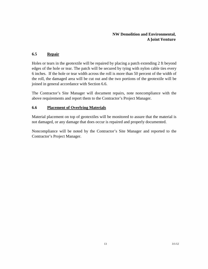
NW Demolition and Environmental, A Joint Venture
13 3/1/12
6.5 Repair
Holes or tears in the geotextile will be repaired by placing a patch extending 2 ft beyond edges of the hole or tear. The patch will be secured by tying with nylon cable ties every 6 inches. If the hole or tear width across the roll is more than 50 percent of the width of the roll, the damaged area will be cut out and the two portions of the geotextile will be joined in general accordance with Section 6.6.
The Contractor’s Site Manager will document repairs, note noncompliance with the above requirements and report them to the Contractor’s Project Manager.
6.6 Placement of Overlying Materials
Material placement on top of geotextiles will be monitored to assure that the material is not damaged, or any damage that does occur is repaired and properly documented.
Noncompliance will be noted by the Contractor’s Site Manager and reported to the Contractor’s Project Manager.

NW Demolition and Environmental, A Joint Venture
14 3/1/12
7. DOCUMENTATION
7.1 General
The effectiveness of CQC depends largely on (i) recognition of construction activities that should be monitored and (ii) assigning responsibilities for the monitoring of each activity. This is effectively accomplished and verified by the documentation of quality assurance activities. The Contractor’s Site Manager will document that quality control requirements have been addressed and satisfied.
The Contractor’s Site Manager will provide the Contractor’s Project Manager with signed descriptive remarks, data sheets, and logs to document that CQA monitoring activities have been carried out. The Contractor’s Site Manager will also maintain, at the job site, a file of the Construction Drawings, Technical Specifications, CQA Plan, checklists, test procedures, daily logs, and other pertinent documents. CQC documentation will be submitted to the Contractor’s Project Manager following completion of the project.
7.2 Record keeping
7.2.1 General
Standard reporting procedures will include preparation of CQC documentation which, at a minimum, will consist of: (i) field notes, including memoranda of meetings and/or discussions with FWS, Contractor’s Project Manager, or the Design Engineer; (ii) CQC monitoring logs and testing data sheets; and (iii) construction problem and resolution summary sheets. This information will be regularly submitted to and reviewed by the Project Manager.
7.2.2 Monitoring Logs and Testing Data Sheets
Monitoring logs and testing data sheets will be prepared as required. At a minimum, these logs and data sheets will include the following information:
• date, project name, location, and other identification;
• weather conditions (i.e., temperature, precipitation);
NW Demolition and Environmental, A Joint Venture
15 3/1/12
• a site plan showing work areas and test locations;
• descriptions and locations of ongoing construction;
• equipment and personnel in each work area related to the R-2 retrofit installation;
• a summary of test results;
• delivery of materials;
• decisions made regarding acceptance of units of work and/or corrective actions to be taken in instances of substandard testing results; and
• signature of the Contractor’s Site Manager.
7.2.3 Construction Problems
The Contractor’s Site Manager will notify the Contractor’s Project Manager of any significant nonconformance with the Construction Documents. The cause of the nonconformance will be determined and appropriate changes to the procedures, or the Construction Documents. These changes will be submitted to the Engineer for review and approval. When this type of evaluation is made, the results will be documented, and the Engineer will approve any revision to the procedures, Construction Drawings, and/or Technical Specifications.
A summary of all supporting data sheets, along with final testing results and the Project Manager’s approval of the work, will be required upon completion of construction.
7.3 Photographic Reporting
Photographs will be taken by the Contractor’s Site Manager and will serve as a pictorial record of work progress, problems, and mitigation activities.
7.4 Design, Technical Specifications, and/or Construction Drawing Changes
Design, Technical Specifications, and/or Construction Drawing changes will be made only with the written approval of the Engineer, and will take the form of an amendment

NW Demolition and Environmental, A Joint Venture
16 3/1/12
to the Technical Specifications and/or the Construction Drawings. Documentation of design, Technical Specifications, and/or Construction Drawing changes will be maintained by NWDE.
7.5 CQA Report
A CQC report will be prepared and submitted to FWS for the final cover system construction elements of the R-2 unit. The report will contain a detailed narrative description of significant aspects of the field and laboratory CQC activities. The documentation of construction activities (presented on the daily field reports) will be included as appendices to the CQA report.
This report will acknowledge: (i) that the work has been performed in compliance with the Construction Drawings, the Technical Specifications, and approved changes; (ii) physical sampling and testing has been conducted at the appropriate frequencies in accordance with the CQA Plan; and (iii) that the summary document provides the necessary supporting information.
At a minimum, this report will include:
• summaries of significant construction activities;
• approved contractor submittals; • monitoring logs and testing data sheets, including sample location plans;
• construction problems and resolution summary sheets, if any;
• approved changes from the design, the Technical Specifications, and/or the
Construction Drawings, if any; and
• record (“as built”) drawings to be prepared by NWDE as outlined in the Technical Specifications;

APPENDIX E
Project Schedules

ID Task Mode
Task Name Duration Start Finish
1 MIDWAY 2012 SCHEDULE
2 General Island work 2 days Tue 7/3/12 Wed 7/4/12
3 Orientation 1 day Tue 7/3/12 Tue 7/3/12
4 Unload barge, set‐up 1 day Wed 7/4/12 Wed 7/4/12
5 R2 Unit 10 days Thu 7/5/12 Wed 7/18/12
6 R2 Prep 10 days Thu 7/5/12 Wed 7/18/12
7 Decision Unit 6 52 days Thu 7/5/12 Fri 9/14/12
8 Building 356 6 days Thu 7/5/12 Thu 7/12/12
9 Abate/Paint 6 days Thu 7/5/12 Thu 7/12/12
10 Building 393 10 days Fri 7/13/12 Thu 7/26/12
11 Abate/Paint 10 days Fri 7/13/12 Thu 7/26/12
12 Soil Remediation 53 days Wed 7/4/12 Fri 9/14/12
13 Apply Meactite 9 days Wed 7/4/12 Mon 7/16/12
14 Excavate/haul to R2 14 days Tue 7/17/12 Fri 8/3/12
15 Sampling & Analysis 7 days Mon 8/6/12 Tue 8/14/12
16 Backfill/haul & Place 23 days Wed 8/15/12 Fri 9/14/12
17 Decision Unit 1 62 days Tue 7/17/12 Wed 10/10/12
18 Building 643 10 days Fri 7/27/12 Thu 8/9/12
19 Abate/Paint 10 days Fri 7/27/12 Thu 8/9/12
20 Demolition 10 days Tue 7/17/12 Mon 7/30/12
21 Demolition of buildings 10 days Tue 7/17/12 Mon 7/30/12
22 Soil Remediation 50 days Thu 8/2/12 Wed 10/10/12
23 Apply Meactite 8 days Thu 8/2/12 Mon 8/13/12
24 Excavate/haul to R2 13 days Tue 8/14/12 Thu 8/30/12
25 Sampling & Analysis 7 days Fri 8/31/12 Mon 9/10/12
26 Backfill/haul & Place 22 days Tue 9/11/12 Wed 10/10/12
27 2012 Project Close‐out 32 days Fri 10/12/12 Mon 11/26/12
28 Demob/clean‐up 2 days Fri 10/12/12 Mon 10/15/12
29 2012 reporting 30 days Tue 10/16/12 Mon 11/26/12
7/1 7/8 7/15 7/22 7/29 8/5 8/12 8/19 8/26 9/2 9/9 9/16 9/23 9/30 10/7 10/14 10/21 10/28 11/4 11/11 11/18 11/25July 2012 August 2012 September 2012 October 2012 November 2012 D
Task
Split
Milestone
Summary
Project Summary
External Tasks
External Milestone
Inactive Task
Inactive Milestone
Inactive Summary
Manual Task
Duration‐only
Manual Summary Rollup
Manual Summary
Start‐only
Finish‐only
Deadline
Progress
MIDWAY 2012 SCHEDULE(showing sequencing of work ‐ task dates subject to change)
Page 1
Project: Midway 1‐24‐12 ver1Date: Mon 2/13/12

ID Task Name Duration Start Finish
1 MIDWAY 2011 SCOPE Decision Unit 6 37 daysWed 9/28/11 Thu 11/17/112 Plans/Submittals 8 days Wed 9/28/11 Fri 10/7/113 Mobilization 30 days Fri 10/7/11 Thu 11/17/114 Shade Cloth installation 26 daysThu 10/13/11 Thu 11/17/115 Lead Paint Abatement/Painting 25 days Fri 10/14/11 Thu 11/17/116 MIDWAY 2012 SCOPE ‐ Completion of Decision
Unit 6/Unit 1101 days Sun 7/1/12 Fri 11/16/12
7 Mobilization 10 days Fri 6/22/12 Thu 7/5/128 Abatement/Painting 30 days Thu 7/5/12 Wed 8/15/129 R2 Unit Prep 5 days Mon 7/30/12 Fri 8/3/1210 Demolition ‐ Decision Unit #1 20 days Wed 8/1/12 Tue 8/28/1211 Soil Removal/Treatment 96 days Fri 7/6/12 Fri 11/16/1212 MIDWAY 2013 SCOPE ‐ Decision Unit 2 102 days Fri 6/21/13Mon 11/11/1313 Mobilization 5 days Mon 6/24/13 Fri 6/28/1314 ACM Abatement 16 days Mon 7/1/13 Mon 7/22/1315 Demolition 30 days Thu 8/1/13 Wed 9/11/1316 Soil Removal/Treatment 96 days Mon 7/1/13Mon 11/11/1317 MIDWAY 2014 SCOPE ‐ Decision Unit 4 101 days Tue 6/24/14 Tue 11/11/1418 Mobilization 5 days Tue 6/24/14 Mon 6/30/1419 Abatement/Painting 35 days Tue 7/1/14 Mon 8/18/1420 Soil Removal/Treatment 96 days Tue 7/1/14 Tue 11/11/1421 MIDWAY 2015 SCOPE ‐ Decision Unit 5 and 7 102 days Tue 6/23/15Wed 11/11/1522 Mobilization 5 days Tue 6/23/15 Mon 6/29/1523 Abatement/Painting 52 days Tue 6/30/15 Wed 9/9/1524 Soil Removal/Treatment 96 days Wed 7/1/15Wed 11/11/1525 MIDWAY 2016 SCOPE ‐ Decision Unit 3 and 8 102 days Fri 6/24/16Mon 11/14/1626 Mobilization 5 days Fri 6/24/16 Thu 6/30/1627 Abatement/Painting 9 days Fri 7/1/16 Wed 7/13/1628 Demolition of Fuel Tanks 20 days Thu 7/7/16 Wed 8/3/1629 Soil Removal/Treatment 96 days Mon 7/4/16Mon 11/14/1630 MIDWAY 2017 SCOPE ‐ Decision Unit 9 99 days Sat 7/1/17 Thu 11/16/1731 Scope to be determined 100 days Sat 7/1/17 Thu 11/16/1732 Demobilization 12 days Wed 11/1/17 Thu 11/16/17
A S O N D J F MAM J J A S O N D J F MAM J J A S O N D J F MAM J J A S O N D J F MAM J J A S O N D J F MAM J J A S O N D J F MAM J J A S O N D J2012 2013 2014 2015 2016 2017 2
Task
Split
Milestone
Summary
Project Summary
External Tasks
External Milestone
Inactive Task
Inactive Milestone
Inactive Summary
Manual Task
Duration‐only
Manual Summary Rollup
Manual Summary
Start‐only
Finish‐only
Deadline
Progress
Page 1
Project: Overall ScheduleDate: Wed 9/28/11